Embed Size (px)
Citation preview

University of Florida Department of Electrical and Computer Engineering
EEL 5666Intelligent Machines Design Laboratory
Spring 2005
Final ReportAutomated Storage & Retrieval System
Instructors: Dr. A. A. Arroyo & Dr. E. M. Schwartz
TAs: William Dubel and Steven Pickles
Student: Albert Chung
Date: 04/19/2005

Table of ContentsI. Abstract ...........................................................................3II. Executive Summary ........................................................4III. Introduction......................................................................5IV. Integrated System............................................................6V. Mobile Platform ...............................................................7VI. Actuation .........................................................................8
i. Drive.......................................................................... 8ii. Forkift....................................................................... 8
VII. Sensors.............................................................................9i. Bump Sensors............................................................9ii. IR Photodetectors.......................................................9iii. IR Proximity Detectors...............................................9iv. IR Remote Control Receiver.....................................10v. RF 2.4GHz Transceivers...........................................10
VIII.Behaviors........................................................................11i. Navigation & Positioning..........................................1 1ii. Communicating.........................................................11iii. Inventory Tracking & Queuing.................................12iv. Storing and Retrieving..............................................12
IX. Experimental Layout and Results ..................................1 3X. Conclusion.......................................................................1 4XI. Sources for Parts............................................................1 5XII. References......................................................................1 6XIII.Source Code....................................................................1 7
- 2 -

I. AbstractLimited floor space in warehouses can hinder the rate of manufacturer production. An economical solution is to utilize the vertical space with an efficient Automated Storage and Retrieval System (ASRS) that can regulate the flow of incoming and outgoing products. An ASRS intelligently picks up pallets from a transition dock and traverses a path to the storage shelf, where it places the pallet securely onto a three tier shelving system. The process can also be reversed. Through RF communication and IR remote control input, tasks to retrieve pallets off the shelf for delivery can be accepted and executed.
- 3 -

II. Executive SummaryWhen it comes down to it, humans make mistakes that can prove to be
costly (and even deadly) in a warehouse environment. These devastating
errors are eliminated by replacing humans with an autonomous agent: the
Automated Storage and Retrieval System, dubbed ASRS. The ASRS comes
to life by navigating high contrast lines on the warehouse floor. It moves
from dock to dock in the process of storing pallets. However, the robust
size of the ASRS prevents it from overcoming the warehousing process by
itself. The AGV is a small, elite vehicle that is capable of flying through a
warehouse at tremendous speeds and feeding the ASRS with pallets. The
brain behind the operation is a high speed PIC microcontroller. It uses five
senses to operate with a high level of intelligence: line follower , distance,
bump, IR remote control, and RF data link. The feedback from individual
sensors is compiled in a central processor, which controls the behavior of
the robot through fine motor control.
In the crusade to keep warehouse prices down, the ASRS stores an
incoming pallet on the first empty shelf it sees, and its memory modules
allow it to remember the location and age of the pallet. The multifunctional
robot is also capable of shipping pallets out of the warehouse. It delivers
the oldest item to the bottom shelf, where the AGV can pick it up and
dispose of it at the outgoing dock. In an attempt to install order, the ASRS
processes jobs on a first-in, first-out basis. Advanced behaviors allow the
- 4 -

ASRS to multitask; it can process incoming requests, traverse the
warehouse, and command the AGV all in the same time frame.
- 5 -

III. Introduction
Modern manufactures have shifted their focus from mass production to selective production in small quantities. While this allows for greater control over company resources such as cash capital and raw materials, it puts a large strain on the warehousing division. Companies can no longer rely on large quantities on the shelf to satisfy customer demands, and instead they must move products quickly off of the factory floor and into the shipping department. There are inherent dangers with such a large rush on product movement.
The first and most important risk a business takes is personal injury. Warehouse floors quickly turn into suburban battle grounds as the work day progresses. Although wide isles can accommodate forklifts operating side by side, there is little margin for error. Gone are the days of small, dirt floor warehouses; modern multimillion dollar facilities measure their warehouse floor in acres. Wider aisles have an inverse affect on warehouse utilization. In addition, human error naturally results in products being misplaced, which can add a tremendous overhead to shipping times.
All of these issues are solved with the introduction of an autonomous vehicle, the Automated Storage and Retrieval system. Because the ASRS can quickly and efficiently store pallets in very narrow aisles, costs are kept down by reducing the square acreage of the warehouse. Standard hazards in the warehouse can be avoided with sensory perception. However, the greatest attribute of the ASRS is its lack of direct human contact. It is capable of handling all aspects of the warehouse: including shipping, receiving, and remembering which jobs it has and has not completed. The ASRS will add an immense amount of value to any company’s warehousing operation.
- 6 -
IV. Integrated SystemA Pic18F8720 microcontroller controls of the functions of the ASRS. The
8720 includes 128kB of programmable memory, 3840B of SRAM, 1kB of
EEPROM and has more than enough data ports that will be required for this
project. There are 16 10-bit ATD converter channels of which 6 are used for
the four line follower sensors and two proximity detectors, 5 PWM channels
to control the motor drivers, two UARTs for barcode data transmission and
for the RF link, and also two 8-bit timers and 3 16-bit timers. Three of the
four external interrupt pins are being used for the IR receiver for remote
control input, RF data ready flag, and high priority fork limit switch. Eight
NiMH batteries provide 9.6V to power the 5V and 3.3V regulators and the
motors.
All of the software was written in C in modular structure and compiled
using the MPLab v7 IDE and MPASM. The functions for the motors, LCD,
analog to digital converter, navigation, RF data link, and behaviors were
coded independently and tested before integration.
- 7 -

Figure 1 Circuitry Layout
- 8 -
PIC 18F8720
LCD
IR Rx
IR Line Follower
Motor Drivers Power Regulator
RF Tx/Rx
IR Proximity Detectors

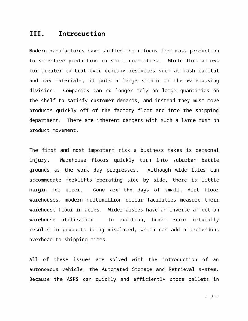
V. Mobile PlatformThe circuitry and motors are encased in a durable platform constructed of
thin craft plywood. The platform was designed to address a top heavy mass
when fully loaded with a pallet. To counter the weight I placed the two
motors in the rear, two casters in the front, and the batteries and
electronics in the rear compartment. I began with rough sketches the
design that I wanted and then drafted a similar design in AutoCAD to be
used for the T-Tech.
- 9 -

Figure 2 Mobile Platform
- 10 -

VI. Actuation
i. DriveThe ASRS achieves forward and reverse mobility by using two 200rpm 12V DC gear-head motors to turn dual wheels fitted with 56mm diameter by 24mm wide Tamiya sport tires. The motors were controlled by sending pulse width modulated signals to a JRC Dual H-Bridge (NJM2670). The motor drivers worked fairly well using the implementation provided in their spec sheet. To reduce the number of PWM outputs required to drive three motors, I multiplexed two signals from the first driver to the third and selected which drivers to control by setting the enables.
I implemented a staircase motor smoothing function to reduce the current spikes of switching the motors on and off. This counters the problem of the initial jerk that the ASRS experienced when switching speeds.
One of the problems that I encountered when running the ASRS on the warehouse floor (see plaza.ufl.edu/tskipp/agv_asrs) is that the rough, uneven surface of the plywood causes the ASRS to bounce fairly hard due to the front casters colliding with the edges of the grooves in the wood. This will force the rear tires to carry all of the weight and stall the motors briefly. At times, it will derail the ASRS from the line causing it to lose its current position. This can easily be solved by ensuring that the surface that the robot operates on is as smooth as possible.
- 11 -
ii. ForkliftThe forklift is raised and lowered by an additional 200rpm 12V DC gear-head motor turning a 1/2” screw with a pitch size of 13. The screw is 13.5” long and provides up to 12” of vertical movement. The center of the screw was bored out ¼” in diameter and ¾” deep in order to attach it to the motor with a set screw. Three quarters of n inch at the opposite end of the screw was milled down to ¼” diameter to allow it to freely rotate inside a sleeve. With the motor turning at full speed, it took less than a minute to travel 12” on a non greased screw.
VII. Sensors
i. Bump SensorsRear bump sensors serve several primitive functions on the ASRS. Two switches were placed on the rear bumper that disables the motors and stops the vehicle when activated. I wired the switches in parallel between ground and a pull up resistor to 3.3V in order to save an I/O pin on my microcontroller. This was suitable for my purposes since the direction that the bump occurs is not important. The switched is polled in software whenever the ASRS is traveling in reverse.
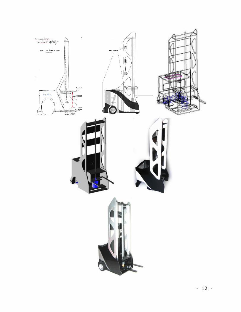
ii. IR PhotodetectorsThe ASRS uses four OPB745 IR emitter/detector pairs to track a line below the below the mobile platform. I found that the lowest price for these sensors were at Mouser Electronics (www.mouser.com) for $3.60 per unit. The OPB745 is composed of an IR LED and a bipolar junction phototransistor whose output is controlled by incoming infrared light entering the base terminal. The best orientation of the device is at around a 15º angle above the surface pivoted on the
- 12 -

phototransistor. About an eighth of an inch clearance provides enough space between the lens and the surface to produce accurate results. I observed that that under indoor lighting, a solid white surface would produce a converted analog value around 70 to 130 and a black electrical tape surface would produce a value above 230. The ASRS is able to dynamically calibrate the threshold to determine a line at system startup to adjust for the different environmental conditions.
iii. IR Proximity detectorsTwo short-range Sharp GPD2D120 IR distance sensors provide forward path vision. The cheapest place to purchase the sensors is from the Mark III Robot Store (www.junun.org) for $8.25 each and a cable can be purchased for an extra $1.10.
I chose the short range sensors rather the long range GPD2D12 sensors due to the tight spaces that the ASRS will be operating in. I didn’t want the robot to be constantly detecting objects in the distance and mistaking the shelving as an obstruction. With the two sensors facing forward and crossing paths, I concluded that a value of 80 translated to around 4cm (minimum distance detection) and anything above 70 represents an obstacle fairly close to the ASRS. When this threshold is reached, the motors are disabled and the ASRS waits until the path is cleared.
iv. IR Remote Control ReceiverThe ASRS uses a Fairchild Semiconductor infrared detector and a Sony television remote control to receive commands from the user. The sensor and implementation is discussed in detail by Trevor Skipp
- 13 -

in his Special Sensor Report which can be found at http://plaza.ufl.edu/tskipp/agv_asrs/photo_sensor.htm.
v. RF 2.4 GHz TransceiverThe ASRS uses a Laipac TRF-2.4G RF wireless transceiver to
communicate with the AGV. The transceiver uses a Nordic nRF2401
VLSI chip with a 16MHz crystal oscillator and a built in dipole
antenna. The benefits of the Laipac transceiver over a standard RF
receiver/transmitter pair are the single chip/device operation for
bidirectional communication, dual channel operation, hardware Cyclic
Redundancy Checksum (CRC) code generation and error checking,
and high speed ShockBurst transmission. The latter three are useful
for microcontroller application since they free up processing power
required to implement a lower level datalink protocol. I purchased
two modules from Spark Fun Electronics (www.sparkfun.com) for
$19.95 each along with two breakout boards that were $0.95 a piece.
The transceiver and implementation is discussed in detail in my
Special Sensor Report which can be found at
http://plaza.ufl.edu/tskipp/agv_asrs/RF.htm.
VIII. Behaviors
i. Navigating & PositioningThe ASRS is capable of traveling from point to point in the warehouse floor and determine its position so long as it maintains on the path. It begins by following closely to the line until it reaches an intersection
- 14 -

at which point it will determine which direction to turn in accordance to three variables: direction, current x coordinate, and destination lane. The ASRS portion of warehouse floor is constructed as a grid system, with one center line and five orthogonal lane extensions that lead to the shelving.
Figure 3 Warehouse Floor & Transition Dock
ii. CommunicatingThe user can communicate objectives to the ASRS by pressing certain buttons on the remote control. When the channel up button is pressed, it signifies that an incoming pallet has arrived at the incoming dock. In this case the ASRS looks up an empty location on the transition dock and notifies the AGV using the RF data link. The input bit and the transition dock number is sent in the packet. To request a pallet, the channel down button is pressed. The ASRS picks up the next outgoing pallet from the shelf and places it onto the transition dock. When completed, the ASRS will notify the AGV by sending the output bit and the dock number.
iii. Inventory Tracking and QueuingThe ASRS maintains an internal database of the shelves using FIFO inventory. The shelf locations are marked with a 0 if it is empty or a
- 15 -
value from 1 to 255 if it is full. Lower values are interpreted as being older pallets that need to exit the warehouse first. The database is scanned whenever an incoming or outgoing request has been made and is changed accordingly whenever pallets enter and leave the shelves.
Up to eight concurrent commands can be sent to the ASRS to be completed through the utilization of a queue stack. This allows the ASRS to finish completing its task before initiating another. It also allows it to wait in idle mode when there are no objectives present.
iv. Storing and RetrievingThe ASRS can store pallets onto different levels using the forklift mechanism discussed under actuation. The different heights are determined by raising or lowering the fork and polling a roller lever switch situated at the height of the shelf behind the fork. This produces very accurate results with no calibration required. Using the switches allows the ASRS to pick up a realistically scaled pallet which has a half inch fork clearance.
- 16 -
IX. Experimental Layout and ResultsEach sensor was tested to determine the functionality and operating conditions of the device. The OPB745 line following sensors gave repeatable values under low light conditions. The results for a white and black surface differed enough to interpret the line accurately. Some measurements using the analog to digital converter are given in Table 1.
Left IR Mid Left IR Mid Right IR Right IR68 77 74 6670 76 79 6866 72 75 7369 81 79 74
192 234 252 207216 249 243 222222 244 234 217209 229 233 230
Table 1 OPB745 Measurements
To test the RF module, I wrote a small routine to increment a counter and send it to another microcontroller without additional error checking protocols. The number of correctly and incorrectly received values were recorded for varying distances. The results are shown below in Table 2. Even at short range operation, the system integrity isn’t very high. Several packets were lost during transmission and some random values were also received. This is likely due to the noise in the communication channel caused by several other household devices (802.11, microwaves, cordless phones, etc) operating at the same frequency. The results confirm that a software protocol must be implemented to retransmit lost packets.
Distance (ft)
Number of Missed Packets
Number of Correctly Sent Packets % Error
3 2 254 0.781255 7 249 2.7343757 2 254 0.781259 7 249 2.734375
11 4 252 1.5625
- 17 -

Table 2 RF Experiment Results
- 18 -

IX. ConclusionThe ASRS performs extremely well under low light conditions since it utilizes several various infrared sensors. Under heavy sunlight the IR remote control receiver will pick up short pulses and continuously interrupt the microcontroller and cause it to lock up in the interrupt routine. This was frustrating since it took a lot of time to figure out why it stopped working in the middle of some routines. This can be fixed by using another small microcontroller to handle the IR and send out the received value to the main microcontroller.
Another problem that I encountered was that the ASRS had to be assisted with placing the pallet correctly on the fork. The forks do not extend far enough to support the rear of the pallet, causing the pallet to become unbalanced and tip backward. This can be changed by simply using a longer fork.
Problems also surfaced when I tried to integrate the Stop and Wait ARQ to the RF data link. The software worked independently but did not work in coherence with the other behaviors. I decided to use parity checking with a header attached to the packet which eliminated most of the random packets that were picked up from noise. The source code for the RF Stop and Wait ARQ is included in the CD accompanying this report.
In the end, all the goals set forth by this project were met. The ASRS and AGV operate together better than I had imagined; although the ASRS is a bit slower than I anticipated. Along with the slow ASRS operation, the current warehouse causes the AGV to be underutilized. There are only five transition dock locations that the AGV can manipulate and it fills up too quickly before the ASRS can remove the pallets. The main problem to consider is the forklift mechanism. I think that a pulley system would reduce the travel time of the fork tremendously and speed up the operation.
- 19 -

XI. Sources for Parts
PIC18F8720 Development Board:www.digikey.com Price:$37.00 each
LED Backlit 16x2 LCD Display:www.junun.orgPrice:$8.50 each
JRC Dual H-Bridge NJM2670www.mouser.comPrice:$2.61 each
200RPM 12V Gear-head Motorwww.jameco.com Price:$21.95 each
Omni-Directional Metal Casterswww.sparkfun.comPrice:$4.95/pair
Tamiya 2.2” Sport Tireswww.sparkfun.comPrice:$5.95/pair
Push Button Switches:IMDL LabPrice: Free
Roller Lever Switches:Radio ShackPrice:$2.50 each (cheaper at Jameco ~ $1.25)
OPB745 IR Emitter/Detector Pairs:www.mouser.comPrice $3.60 each
Sharp GPD2D12 Distance Measuring Sensors:www.junun.orgPrice: $8.25 each (+$1.10 for a cable)
- 20 -

XII. References
Microchip PIC18F8720 Datasheet:
http://ww1.microchip.com/downloads/en/DeviceDoc/39609b.pdf
Optek OPB745 Datasheet:
http://www.optekinc.com/pdf/OPB745.pdf
JRC Dual H-Bridge NJM2670 Datasheet:
- 21 -

http://www.njr.co.jp/pdf/bj/bj10021.pdf
Nordic Semiconductor nRF2401 Datasheet:
http://www.sparkfun.com/datasheets/RF/nRF2401rev1_1.pdf
Sharp GPD2D120 Datasheet:
http://www.junun.org/MarkIII/datasheets/GP2D120.pdf
Laipac TRF-2.4G Datasheet:
http://www.sparkfun.com/datasheets/RF/RF-24G_datasheet.pdf
Steven Pickles’ Final Report
http://www.mil.ufl.edu/imdl/papers/IMDL_Report_Spring_04/pickles_steven/kirby.pdf
William Dubel’s Reliable Line Tracking Report:
http://www.mil.ufl.edu/imdl/handouts/lt.doc
- 22 -

XIII. Source Code
/*********************************************************** * AUTOMATED STORAGE & RETRIEVAL SYSTEM * * * * EEL5666 Intelligent Machines Design Laboratory * * University of Florida * * Written for the PIC18F8720 @ 20 MHz * * Copyright (2005) Albert Chung 2.12.2005 * ************************************************************/
#include <p18f8720.h>#include <delays.h>#include <stdio.h>#include "adconv.h"#include "bios.h"#include "motors.h"#include "rf.h"#include "interrupts.h"#include "nav.h"#include "asrs.h"
#pragma config OSC = HS#pragma config WDT = OFF#pragma config LVP = ON#pragma config MODE = MC
#define rear_bump PORTBbits.RB4
void main(void){
unsigned char i;
DDRD = 0x00;DDRB = 0xFF;DDRH = 0x00;
DDRC = DDRC & 0b11111011; DDRG = DDRG & 0b11100110;
DDRE = DDRE | 0b01111100;
PWM_Init();Motors(0,0);
LCD_Init();
sprintf(message, " :::ASRS::: Press Rear Bump");UPDATE_LCD;
Init_Fork_Limit_IRQ();
Init_RF();
Init_IR_IRQ();
GLOBAL_IRQ_ON;
for( i = 0; i < 15; i++ ) // Clear the shelves{
shelves[i] = 0;}
while( rear_bump == 1 ){ }
- 23 -

Calibrate_LF();
sprintf(message, "Preparing Fork");UPDATE_LCD;
Initialize_Fork();
shelves[8] = 1; // preload the pallets on the shelvesshelves[7] = 2;shelves[10] = 3;shelves[14] = 4;shelves[11] = 5;
sprintf(message, "...Waiting For Command...");UPDATE_LCD;
while (1){
if (first != last){
Move_Pallet();}
}
return;}
- 24 -

/**************************************************** * AUTOMATED STORAGE & RETRIEVAL SYSTEM * * * * Behavioral Routines: Storing, Inventory, Queuing * * * * EEL5666 Intelligent Machines Design Laboratory * * University of Florida * * Written for the PIC18F8720 @ 20 MHz * * Copyright (2005) Albert Chung 2.12.2005 * ****************************************************/
#include <p18f8720.h>#include <delays.h>#include "motors.h"#include "nav.h"#include "asrs.h"#include "bios.h"#include <stdio.h>
#define tier_1 PORTEbits.RE3 // Active High#define tier_2 PORTEbits.RE4 // Active Low#define tier_3 PORTEbits.RE5 // Active Low
// Shelf Location Variablesunsigned char shelves[15] = {0};unsigned char shelf_num;unsigned char last_age = 2;unsigned char first_age = 1;unsigned char tier_height;unsigned char IO;unsigned char last_fork_height; // 0: lower switch limit, 1: tier 1, 2: tier 2, 3: tier 3, 4: upper switch limit
// Queue variablesunsigned char Queue[QUEUE_LENGTH];signed char first = 0;signed char last = 0;
/****************************************************** * Move_Pallet: Runs through the steps necessary * * move a pallet across the warehouse floor. Acts * * as an arbitrator for the motors and servo. * *******************************************************/
void Move_Pallet(void){
unsigned char packet, IO, temp;
packet = Queue_Pull();
if( (packet & 0b00001000) == 0b00001000 ) // Pallet entering the system{
IO = 1;shelf_num = packet & 0b00000111;
sprintf(message, "Picking Up Incoming Pallet");UPDATE_LCD;
}else // Pallet leaving the system{
IO = 0; // Get the location of the first pallet to goshelf_num = Get_Out_Location();
sprintf(message, "Picking Up Outgoing Pallet");UPDATE_LCD;
}
Delay10KTCYx(0);
- 25 -

Get_Destination(shelf_num); // Set the x coordinate and tier height
if( (x_dest != x_cur) && (direction == 3) ){
Turn_Around(); // Not already at location and facing the shelvesNavigate(); // Follow center line until destination lane is reached
}else if ( (direction == 0) || (direction == 2) ){
Navigate(); // Follow center line until destination lane is reached}
sprintf(message, "Positioning ForkTo Tier %d", tier_height);UPDATE_LCD;
Center_Fork_To_Pallet(); // Once arrived at destination, raise or lower fork to the center of the pallet
Motors(MF_FORWARD, MF_FORWARD); // Get off the lineDelay10KTCYx(175);
Navigate(); // Drive in
sprintf(message, "Picking Pallet Up ");UPDATE_LCD;
Raise_Fork(); // Lift pallet above shelf
shelves[shelf_num] = 0;
Back_Up(); // Drive out
sprintf(message, "Positioning ForkTo Tier %d", tier_height);UPDATE_LCD;
Center_Fork_To_Pallet(); // Lower the fork
// go to second set of (x,y) coordinates
if( IO == 1 ) // Pallet entering the system{ // Go to the shelves second
shelf_num = Get_In_Location(); // Find an empty location on shelf to place pallet}else // Pallet leaving the system{ // Go to dock second
shelf_num = Get_Dock_Location(); // Find an empty location on dock to place pallet}
Get_Destination(shelf_num); // Set the x coordinate and tier height
if( (x_dest != x_cur) ) // Already at location{
Turn_Around();Navigate(); // Follow center line until destination lane is reached
}
sprintf(message, "Positioning ForkTo Tier %d", tier_height);UPDATE_LCD;
Center_Fork_To_Pallet(); // once arrived, raise or lower fork to the tier
Raise_Fork(); // Lift pallet above shelf
Motors(MF_FORWARD, MF_FORWARD); // Get off the lineDelay10KTCYx(175);
Navigate(); // Drive in
Center_Fork_To_Pallet(); // Lower pallet onto shelf
- 26 -

// if outgoing, tell agv to pick up the palletif (IO == 0) // Pallet leaving the system{
sprintf(message, "Requesting AGV Pickup");UPDATE_LCD;
Transmit(shelf_num); // send shelf number where the output resides to the AGV}
Back_Up();
sprintf(message, "Mission Complete");UPDATE_LCD;
Delay10KTCYx(0);
sprintf(message, "...Waiting For Command...");UPDATE_LCD;
return;}
/*********************************************** * Queue_Pull: Pull a request off of the queue. * ************************************************/
unsigned char Queue_Pull(void){
unsigned char temp;
temp = Queue[first];
first++;
if( first == QUEUE_LENGTH ){
first = 0;}
return temp;}
/************************************************* Queue_Push: Push a request onto the queue. * *************************************************/
void Queue_Push(unsigned char packet){
Queue[last] = packet;
last++;
if( last == QUEUE_LENGTH ){
last = 0;}
return;}
/***************************************************** Get_Destination: Extracts the x destinations ** and the tier height from the data packet * *****************************************************/
void Get_Destination(unsigned char shelf_num){
// set destination x coordinate and tier height
- 27 -

if( shelf_num < 5 ){
tier_height = 1;x_dest = shelf_num;
}else if( shelf_num < 10 ){
tier_height = 2;x_dest = shelf_num - 5; // Offset of 5
}else // shelf_num < 15{
tier_height = 3;x_dest = shelf_num - 10;
}
return;}
/***************************************************** Get_Dock_Location: Finds and returns an empty ** location on the transition dock. * *****************************************************/
unsigned char Get_Dock_Location(void){
unsigned char i;
for( i = 0; i < 5; i++ ){
if( shelves[i] == 0 ){
shelves[i] = 1; // Mark as fullreturn i;
}}
- 28 -
return;}
/***************************************************** Get_In_Location: Finds and returns an empty ** location on the shelves. * *****************************************************/
unsigned char Get_In_Location(void){
unsigned char i;
for (i = 5; i < 15; i++){
if (shelves[i] == 0) // Location is empty{
shelves[i] = last_age;last_age++;return i;
}}
return;}
- 29 -

/***************************************************** Get_Out_Location: Finds and returns the ** location of the oldest product on the shelves. * *****************************************************/
unsigned char Get_Out_Location(void){
unsigned char i;
for (i = 5; i < 15; i++){
if (shelves[i] == first_age) // Oldest product = first to go{
shelves[i] = 0; // Empty the the locationfirst_age++;return i;
}}
return;}
/***************************************************** Initialize_Fork: Initializes the fork to a *
- 30 -
* known state/height. * *****************************************************/
void Initialize_Fork(void){
unsigned char temp, temp2 = 0;
Fork(UP); // Raise fork
for( temp = 0; temp < 25; temp++ ) // Delay half a second{
if( tier_1 == 1 || tier_2 == 0 || tier_3 == 0 ){
Fork(STOP);}
Delay1KTCYx(0);}
Fork(DOWN); // Lower fork
while( temp2 == 0 ) // Wait for fork to press a switch{
if( tier_1 == 1 ) // Active High{
Delay1KTCYx(100); // Delay 20msec to debounce switch
- 31 -

while( tier_1 == 1 ) // Wait for fork to get off the switch (active high){ }
Fork(STOP); // Stop fork
last_fork_height = 1;
temp2 = 1;}else if( tier_2 == 0 ) // Active Low{
Delay1KTCYx(100); // Delay 20msec to debounce switch
while( tier_2 == 0 ) // Wait for fork to get off the switch (active high){ }
Fork(STOP); // Stop fork
last_fork_height = 2;
temp2 = 1;}else if( tier_3 == 0 ) // Active Low{
Delay1KTCYx(100); // Delay 20msec to debounce switch
- 32 -

while( tier_3 == 0 ) // Wait for fork to get off the switch (active high){ }
Fork(STOP); // Stop fork
last_fork_height = 3;
temp2 = 1;}
}
sprintf(message, "Fork initializedto tier %d", last_fork_height);UPDATE_LCD;
Delay10KTCYx(0);Delay10KTCYx(0);Delay10KTCYx(0);
return;}
void Center_Fork_To_Pallet(void){
switch(tier_height){
case 1:{
- 33 -
if( last_fork_height > 1 ){
Fork(DOWN); // Lower fork
while( tier_1 != 1 ) // Wait for fork to press the switch (active high){ }
Delay1KTCYx(100); // Delay 20msec to debounce switch
while( tier_1 == 1 ) // Wait for fork to get off the switch (active high){ }
}
Fork(STOP); // Stop fork
last_fork_height = 1;break;
}case 2:{
if( last_fork_height > 2 ){
Fork(DOWN); // Lower fork
while( tier_2 != 0 ) // Wait for fork to press the switch{ }
- 34 -

Delay1KTCYx(100); // Delay 20msec to debounce switch
while( tier_2 == 0 ) // Wait for fork to get off the switch{ }
}else if( last_fork_height < 2 ){
Fork(UP); // Raise fork
while( tier_2 != 0 ){ }
}
Fork(STOP); // Stop fork
last_fork_height = 2;break;
}case 3:{
if( last_fork_height > 3 ){
Fork(DOWN); // Lower fork
while( tier_3 != 0 ) // Wait for fork to press the switch{ }
- 35 -
Delay1KTCYx(100); // Delay 20msec to debounce switch
while( tier_3 == 0 ) // Wait for fork to get off the switch{ }
}else if( last_fork_height < 3 ){
Fork(UP); // Raise fork
while( tier_3 != 0 ) // Wait for fork to press switch{ }
}
Fork(STOP); // Stop fork
last_fork_height = 3;break;
}}
Fork(UP);Delay10KTCYx(175);Fork(STOP);
return;}
/***************************************************** Raise_Fork: Raises the fork * *****************************************************/
void Raise_Fork(void){
unsigned char i;
last_fork_height = 4;
Fork(UP);
Delay10KTCYx(0); // Raise fork for 3 secondsDelay10KTCYx(0);Delay10KTCYx(0);Delay10KTCYx(0);Delay10KTCYx(0);Delay10KTCYx(0);Delay10KTCYx(0);
Fork(0); // Stop the fork
return;}
- 36 -

/***********************************************************
- 37 -

* HITACHI LCD CONTROLLER * * * * Written for the PIC18F8720 @ 20 MHz * * Interfaces: Enable on RD0, RS on RD1, DB4:7 on * * RD4:7 * * Copyright 2005 Albert Chung & Trevor Skipp * ***********************************************************/
#include <p18f8720.h>#include <delays.h>#include "bios.h"
#define lcdport PORTD#define EN PORTDbits.RD0#define RS PORTDbits.RD1
void LCD_Init(void);void LCD_En(void);void LCD_Write(char data);void LCD_Command(int);void Update_LCD(void);
char message[40];
- 38 -

/*********************************************************** * printlcd: Sends a string one character at a time * * to LCD_Write. * ***********************************************************/
void Update_LCD(void){
int i, j;
LCD_Command(0x01); // Clear display & return cursor homeDelay10KTCYx(5); // 5 msec
for(i = 0; i < 32; i++){
if ( message[i] == '\0' ){
break;}
if (i == 16){
for(j = 0; j < 24; j++){
LCD_Write(' ');}
LCD_Write(message[i]);}
- 39 -
else{
LCD_Write(message[i]);}
}
return;}
/**************************************************** * LCD_En: Enables the LCD. This tells the LCD to * * read in data. * ****************************************************/void LCD_En(void){
Delay10TCYx(100); // 50 usec EN = 1; // PORTDbits.RD0 = 1Delay10TCYx(100); // 50 usecEN = 0; // PORTDbits.RD0 = 0Delay10TCYx(100); // 50 usec
return;}
- 40 -
/**************************************************** * LCD_Init: Initializes the LCD for 4 bit mode, * * 2 lines, 5x11 dot matrix, display on, cursor * * off, blink off, clear screen, return cursor * * home, increment cursor to the right, and don't * * shift the screen. * ****************************************************/void LCD_Init(void){
int i;int setup[] = {0x33, 0x32, 0x2C, 0x0C, 0x01, 0x06};
Delay10KTCYx(40); // 20 msec power up
for (i = 0; i < 6; i++){
LCD_Command(setup[i]);Delay10KTCYx(10); // 5 msec
}
return;}
/**************************************************** * LCD_Command: Modify data to set RS (Register * * Select) to command mode. Sends data to the LCD.* ****************************************************/
- 41 -
void LCD_Command(int command){
int temp;
RS = 0; // PORTDbits.RD1 = 0
temp = command & 0xF0; // Mask off lower nibblelcdport &= 0x0F; // Clear upper nibblelcdport |= temp;LCD_En();
Delay10TCYx(110); // 55 usec
temp = command << 4;temp &= 0xF0; // Clear upper nibblelcdport &= 0x0F;lcdport |= temp;LCD_En();
return;}
/**************************************************** * LCD_Write: Reads in the argument and displays it * * on the LCD. * ****************************************************/void LCD_Write(char data){
int temp;
RS = 1; // PORTDbits.RD1 = 1
temp = data & 0xF0; // Mask off lower nibblelcdport &= 0x0F; // Clear upper nibblelcdport |= temp;LCD_En();
Delay10TCYx(110); // 55 usec
temp = data << 4;temp &= 0xF0;lcdport &= 0x0F; // Clear upper nibblelcdport |= temp;LCD_En();
return;}
- 42 -

/****************************************************
- 43 -

* ANALOG TO DIGITAL CONVERSION * * * * Written for the PIC18F8720 @ 20 MHz * * Interfaces: Analog inputs on ANO:5 * * Copyright 2005 Trevor Skipp * * * * NOTES: * * The followig code is for 8 analog channels, and * * the remaining pins are set to digital I/O. If * * more analog channels are desired, adjust * * ADCON1 in each function, and follow the * * pattern in the functions. * * A delay is required before a subsequent sample. * * This is the delay before the return statement * * in each function. This delay could be moved * * or eliminated (i.e. you will not be taking * * samples back to back) to free up processor * * cycles. * ****************************************************/
#include <p18f8720.h>#include <delays.h>#include "adconv.h"
int Read_AD0();int Read_AD1();
- 44 -
int Read_AD2();int Read_AD3();int Read_AD4();int Read_AD5();void Poll_AD_Done(void);
// Line Following declarationsint black_l, black_ml, black_mr, black_r;int line_data;int prev_line_data;
/**************************************************** * Poll_AD_Done: Poll until the conversion is * * complete. * ****************************************************/void Poll_AD_Done(void){
for(;;){
if (ADCON0 & 0b00000001 == 0b00000001){
return;}
}}
/****************************************************
- 45 -

* Read_ADx: Select "x" analog channel and sample * * it. Returns the 8 bit value of the analog * * channel. * ****************************************************/int Read_AD0(void){
ADCON1 = 0b00000111; //Vref+ = External Vref + (5V to pin 27), Vref- = Vss, ANO:5 analog in, AN6:15 digital I/O (PAGE 214)
ADCON0 = 0b00000000; //select ADO, set "GO", and ADON off (PAGE 213)
ADCON2 = 0b00000010; //left justify, conversion time = 64 * Tosc (PAGE 215)ADCON0 = 0b00000001; //turn on A/D module
Delay10TCYx(13); //6.5us
ADCON0 = 0b00000011; //GO
Poll_AD_Done();
Delay10TCYx(35); //23us
return ADRESH;}
int Read_AD1(void){
ADCON1 = 0b00000111; //Vref+ = External Vref + (5V to pin 27), Vref- = Vss, ANO:5 analog in, AN6:15 digital I/O (PAGE 214)
- 46 -
ADCON0 = 0b00000100; //select AD1, set "GO", and ADON off (PAGE 213)
ADCON2 = 0b00000010; //left justify, conversion time = 64 * Tosc (PAGE 215)ADCON0 = 0b00000101; //turn on A/D module
Delay10TCYx(13); //6.5us
ADCON0 = 0b00000111; //GO
Poll_AD_Done();
Delay10TCYx(35); //23us
return ADRESH;}
int Read_AD2(void){
ADCON1 = 0b00000111; //Vref+ = External Vref + (5V to pin 27), Vref- = Vss, ANO:5 analog in, AN6:15 digital I/O (PAGE 214)
ADCON0 = 0b00001000; //select AD2, set "GO", and ADON off (PAGE 213)
ADCON2 = 0b00000010; //left justify, conversion time = 64 * Tosc (PAGE 215)ADCON0 = 0b00001001; //turn on A/D module
Delay10TCYx(13); //6.5us
- 47 -
ADCON0 = 0b00001011; //GO
Poll_AD_Done();
Delay10TCYx(35); //23us
return ADRESH;}
int Read_AD3(void){
ADCON1 = 0b00000111; //Vref+ = External Vref + (5V to pin 27), Vref- = Vss, ANO:5 analog in, AN6:15 digital I/O (PAGE 214)
ADCON0 = 0b00001100; //select AD3, set "GO", and ADON off (PAGE 213)
ADCON2 = 0b00000010; //left justify, conversion time = 64 * Tosc (PAGE 215)ADCON0 = 0b00001101; //turn on A/D module
Delay10TCYx(13); //6.5us
ADCON0 = 0b00001111; //GO
Poll_AD_Done();
Delay10TCYx(35); //23us
- 48 -
return ADRESH;}
int Read_AD4(void){
ADCON1 = 0b00000111; //Vref+ = External Vref + (5V to pin 27), Vref- = Vss, ANO:5 analog in, AN6:15 digital I/O (PAGE 214)
ADCON0 = 0b00010000; //select AD4, set "GO", and ADON off (PAGE 213)
ADCON2 = 0b00000010; //left justify, conversion time = 64 * Tosc (PAGE 215)ADCON0 = 0b00010001; //turn on A/D module
Delay10TCYx(13); //6.5 us
ADCON0 = 0b00010011; //GO
Poll_AD_Done();
Delay10TCYx(35); //23us
return ADRESH;}int Read_AD5(void){
ADCON1 = 0b00000111; //Vref+ = External Vref + (5V to pin 27), Vref- = Vss, ANO:5 analog in, AN6:15 digital I/O (PAGE 214)
ADCON0 = 0b00010100; //select AD5, set "GO", and ADON off (PAGE 213)
- 49 -
ADCON2 = 0b00000010; //left justify, conversion time = 64 * Tosc (PAGE 215)ADCON0 = 0b00010101; //turn on A/D module
Delay10TCYx(13); //6.5us
ADCON0 = 0b00010111; //GO
Poll_AD_Done();
Delay10TCYx(35); //23us
return ADRESH;}
int Read_AD6(void){
ADCON1 = 0b00000111; //Vref+ = External Vref + (5V to pin 27), Vref- = Vss, ANO:5 analog in, AN6:15 digital I/O (PAGE 214)
ADCON0 = 0b00011000; //select AD6, set "GO", and ADON off (PAGE 213)
ADCON2 = 0b00000010; //left justify, conversion time = 64 * Tosc (PAGE 215)ADCON0 = 0b00011001; //turn on A/D module
Delay10TCYx(13); //6.5us
ADCON0 = 0b00011011; //GO
Poll_AD_Done();
Delay10TCYx(35); //23us
return ADRESH;}
int Read_AD7(void){
ADCON1 = 0b00000111; //Vref+ = External Vref + (5V to pin 27), Vref- = Vss, ANO:5 analog in, AN6:15 digital I/O (PAGE 214)
ADCON0 = 0b00011100; //select AD7, set "GO", and ADON off (PAGE 213)
ADCON2 = 0b00000010; //left justify, conversion time = 64 * Tosc (PAGE 215)ADCON0 = 0b00011101; //turn on A/D module
Delay10TCYx(13); //6.5us
ADCON0 = 0b00011111; //GO
Poll_AD_Done();
Delay10TCYx(35); //23us
return ADRESH;}
- 50 -

/*********************************************************** * Interrupt Polling * * * * Written for the PIC18F8720 * * Interfaces: * * High Priority interrupts: INT0 -> Lower Fork Limit * * INT3 -> Upper Fork Limit * * Low Priority interrupts: INT1 -> TRF-24G RD1 * * INT2 -> Rear Bump switches * * (falling edge) * * * * Credits: Microchip * * Written by Albert Chung & Trevor Skipp * ***********************************************************/
#include <p18f8720.h>#include <stdio.h>#include "rf.h"#include "bios.h"#include "motors.h"#include "interrupts.h"#include "asrs.h"
#define driver2_en PORTDbits.RD3
void low_isr(void);void high_isr(void);void Init_Int(void);void Disable_TMR0_IRQ(void);void Init_TMR1_Overflow_IRQ(void);
// RF Stop and Wait ARQ#define TIMEOUT_SIZE 3unsigned char timeout_ctr = 0;unsigned char num_timeouts = 0;
int my_count;
// IR Detector variablesunsigned char count;unsigned char data[5];unsigned char remote;unsigned char num_overflows;unsigned char skip = 5; // Used to skip the first 5 IR samples on startup, subsequent IR samples must skip 6unsigned char manual_mode = 0;
int forward = 100;int reverse = -100;
/************************************************************* For PIC18 devices the low interrupt vector is found at ** 00000018h. The following code will branch to the ** low_interrupt_service_routine function to handle ** interrupts that occur at the low vector. **************************************************************/
#pragma code low_vector=0x18void interrupt_at_low_vector(void){_asm GOTO low_isr _endasm}#pragma code /* return to the default code section */
#pragma interruptlow low_isrvoid low_isr (void){
int ir_watchdog = 0;unsigned char temp1, temp2;
- 51 -

if ( INTCON3bits.INT2IF == 1) // IR triggered interrupt{
T3CON = 0b00000001;
// Skip the first 5 samples
for(count = 0; count < 5; count++){
while (PORTBbits.RB2 == 0) //wait for rising edge{}
while (PORTBbits.RB2 == 1) //wait for falling edge{}
}
// Grab the length of the next 5 high pulses
for(count = 0; count < 5; count++){
TMR3H = 0x00;TMR3L = 0x00;
while (PORTBbits.RB2 == 0) //wait for rising edge{}
while (PORTBbits.RB2 == 1) //wait for falling edge{}
if (TMR3H > 20){
data[count] = 1;}else{
data[count] = 0;}
}
if (skip == 5){
skip = 6;}
// Convert data[] into an integer
count = 0;remote = 0;
if (data[count++] == 1){
remote |= 0b00001;}if (data[count++] == 1){
remote |= 0b00010;}if (data[count++] == 1){
remote |= 0b00100;}if (data[count++] == 1){
remote |= 0b01000;}if (data[count] == 1)
- 52 -

{remote |= 0b10000;
}
// "remote" now contains the hex code for the remote button
if( remote == 17 ) // Channel Up ( package entering system ){
temp1 = Get_Dock_Location();temp2 = temp1 | 0b00001000;Transmit(temp2);
sprintf(message, "Incoming Request Sent To AGV");UPDATE_LCD;
}else if( remote == 18 ) // Channel Down ( package leaving system ){
Queue_Push(0b00000111);
sprintf(message, "Outgoing Request Placed On Queue");UPDATE_LCD;
}
Delay10KTCYx(0);Delay10KTCYx(0);
INTCON3bits.INT2IF = 0; // Clear INT2 flag}
if ( INTCON3bits.INT1IF == 1) // RF Rx data ready {
Receive();
INTCON3bits.INT1IF = 0; // Clear the INT1 Flag}
if (INTCONbits.TMR0IF == 1) // TMR0 overflowed (no ACK recieved){
if( num_timeouts == 3 ){
if( timeout_ctr < TIMEOUT_SIZE ){
Disable_TMR0_IRQ();Transmit(tx_buffer); // Other terminal missed the packet / resendtimeout_ctr++;
}else // Give up sending data{
Disable_TMR0_IRQ();timeout_ctr = 0;
}
num_timeouts = 0;}
num_timeouts++;
INTCONbits.TMR0IF = 0; // Clear the TMR0 overflow Flag}
}
/************************************************************* For PIC18 devices the high interrupt vector is found at ** 00000008h. The following code will branch to the ** high_interrupt_service_routine function to handle ** interrupts that occur at the high vector. **************************************************************/
#pragma code high_vector=0x08
- 53 -
void interrupt_at_high_vector(void){_asm GOTO high_isr _endasm}#pragma code /* return to the default code section */
#pragma interrupt high_isrvoid high_isr (void){
if ( PIR2bits.TMR3IF == 1) // Timer 3 overflowed{
if (++num_overflows == 30){
INTCON3bits.INT2IE = 1; // Enable INT1 XIRQPIE2bits.TMR3IE = 0; // Disable interuptnum_overflows = 0;
}
PIR2bits.TMR3IF = 0; // Clear flag}
if ( PIR2bits.CCP2IF == 1) // Capture pin triggered{
// ...PIR2bits.CCP2IF = 0; // Clear the INT0 Flag
}
if ( PIR1bits.TMR1IF == 0) // Timer 1 overflowed{
// ...PIR1bits.TMR1IF = 0;
}
if ( INTCONbits.INT0IF == 1) // Fork limit reached{
Fork(STOP); // Stop the fork
driver2_en = 0; // Disable the fork motor driver
sprintf(message, "Fork Limit Reached!");UPDATE_LCD;
INTCONbits.INT0IF = 0; // Clear the INT0 Flag
while(1) // Do nothing until reset{}
}}
/************************************************************* Initialize interrupts **************************************************************/
void Init_Global_IRQ(void){
RCONbits.IPEN = 1; // Enable interrupt priorityINTCONbits.GIEH = 1; // Enable all high priority interruptsINTCONbits.GIEL = 1; // Enable all low priority interrupts
return;}
void Disable_Global_IRQ(void){
INTCONbits.GIEH = 0; // Enable all high priority interruptsINTCONbits.GIEL = 0; // Enable all low priority interrupts
- 54 -

return;}
void Init_TMR3_Overflow_IRQ(void){
IPR2bits.TMR3IP = 1; // High priorityPIR2bits.TMR3IF = 0; // Clear flagPIE2bits.TMR3IE = 1; // Enable interrupt
return;}
void Init_RF_IRQ(void){
INTCON2bits.INTEDG1 = 1; // INT1 = rising edge interruptINTCON3bits.INT1IP = 0; // INT1 = low priority interruptINTCON3bits.INT1IF = 0; // Clear the INT1 FlagINTCON3bits.INT1IE = 1; // Enable INT1 XIRQ
return;}
void Disable_RF_IRQ(void){
INTCON3bits.INT1IE = 0; // Disable INT1 XIRQ
return;}
void Init_TMR0_IRQ(void){
INTCON2bits.TMR0IP = 0; // TMR0 = low priority interruptINTCONbits.TMR0IF = 0; // Clear the TMR0 overflow Flag
// 400 ms timer flagT0CON = 0b10000101; // Timer0 on, 16 bit, instruction clk (5MHz), low to high
// transition increment, prescale on, 5MHz/64TMR0H = 0; // Clear the TimerTMR0L = 0;
INTCONbits.TMR0IE = 1; // Enable TMR0 overflow IRQ
return;}
void Disable_TMR0_IRQ(void){
T0CON = 0; // Turn off the timerINTCONbits.TMR0IE = 0; // Disable TMR0 overflow IRQ
return;}
void Init_IR_IRQ(void){
INTCON2bits.INTEDG2 = 0; // INT2 = falling edge interruptINTCON3bits.INT2IP = 0; // INT2 = low priority interruptINTCON3bits.INT2IF = 0; // Clear the INT2 FlagINTCON3bits.INT2IE = 1; // Enable INT2 XIRQ
// Configure Timer1 which is used in subroutine
T1CON = 0b00000001;
return;}
- 55 -

void Init_Fork_Limit_IRQ(void){
INTCON2bits.INTEDG0 = 0; // INTO = falling edge interruptINTCONbits.INT0IF = 0; // Clear the INT0 flagINTCONbits.INT0IE = 1; // Enable INT0 XIRQ
return;}
- 56 -

/**************************************************** * MOTOR CONTROLLER * * * * Written for the PIC18F8720 @ 20 MHz * * Interfaces: Digital outputs on CCP1,3,4,5 that * * connect to a JRC Dual H-Bridge NJM2670. * * Copyright (2005) Trevor Skipp & Albert Chung * * * * NOTES: * * The PWM output pins CCP1,3,4,5 must be set to * * outputs in the main function. * * DDRC = DDRC & 0b11111011; * * DDRG = DDRG & 0b11100110; * * 8 bit resolution * * The JRC chip uses 2 PWM inputs to control each * * motor. No direction pin is used. * * CCP1: Left motor (-) / Fork motor (+) * * CCP3: Left motor (+) / Fork motor (-) * * CCP4: Right motor (+) * * CCP5: Right motor (-) * * RD2: Motor Driver 1 Enable * * RD3: Motor Driver 2 Enable * ****************************************************/
#include <p18f8720.h>#include <delays.h>#include "interrupts.h"#include "bios.h"#include <stdio.h>
#define driver1_en PORTDbits.RD2#define driver2_en PORTDbits.RD3#define lower_fork_limit PORTEbits.RE2#define upper_fork_limit PORTEbits.RE6#define step_size 5
int left_old_speed = 0;int left_new_speed = 0;
int right_old_speed = 0;int right_new_speed = 0;
unsigned char fork_direction;
/**************************************************** * PWM_Init: Initialize the PWM module for 4 DC * * motors using Timer 2 and 1 servo using Timer 1. * ****************************************************/
void PWM_Init(void){
PR2 = 0xFF; //Period
CCPR1L = 0; //Duty cycle = 0CCPR3L = 0;CCPR4L = 0;CCPR5L = 0;
T2CON = 0b00000101; //Timer 2: no postscale, module on, and 4 prescaler
CCP1CON = 0b00001100; //PWM mode and Duty cycle's LSB1:0 = 0CCP3CON = 0b00001100;CCP4CON = 0b00001100;CCP5CON = 0b00001100;
return;}
/*****************************************************
- 57 -

* Fork: Raise or lower the fork. * *****************************************************/ void Fork(signed char direction){
fork_direction = direction;
driver1_en = 0;driver2_en = 1;
if (direction == 1) //Full Up 100%{ CCPR1L = 0b11111111;
CCPR3L = 0;}else if (direction == 0) //Stop{
CCPR1L = 0;CCPR3L = 0;
}else if (direction == -1) //Full Down 100%{
CCPR1L = 0;CCPR3L = 0b11111111;
}
return;}
/***************************************************** * Motors: Adjust the DC motor speed. Implement * * a smoothing function to improve driving. * ******************************************************/ void Motors(int left_desired_speed, int right_desired_speed){
int i = 1;
driver1_en = 1;driver2_en = 0;
while( (left_new_speed != left_desired_speed) || (right_new_speed != right_desired_speed) ){
if (left_desired_speed > left_old_speed){
left_new_speed = left_old_speed + step_size; }else if( left_desired_speed < left_old_speed ){
left_new_speed = left_old_speed - step_size;}
if( right_desired_speed > right_old_speed ){
right_new_speed = right_old_speed + step_size; }else if( right_desired_speed < right_old_speed ){
right_new_speed = right_old_speed - step_size;}
if ( left_new_speed >= 0 ){
CCPR1L = left_new_speed; // left motor forwardCCPR3L = 0;
}else{
CCPR3L = -1*left_new_speed; // left motor reverse
- 58 -
CCPR1L = 0;}
if ( right_new_speed >= 0 ){
CCPR4L = right_new_speed; // right motor forwardCCPR5L = 0;
}else{
CCPR5L = -1*right_new_speed; // right motor reverseCCPR4L = 0;
}
left_old_speed = left_new_speed;right_old_speed = right_new_speed;
Delay10TCYx(1);
}
return;}
- 59 -
/*********************************************************** * LINE FOLLOWING * * * * Written for the PIC18F8720 @ 20 MHz * * Interfaces: Digital I/O on RH0, RH1, RH2, RH3, * * and INT1, that connect to a TRF-24G RF module * * Copywrite 2005 Albert Chung and Trevor Skipp * * * * NOTES: * * Hardware Connections: * * LEFT_IR: AN4 * * MID_LEFT_IR: AN5 * * MID_RIGHT_IR: AN6 * * RIGHT_IR: AN7 * *************************************************************/
#include <p18f8720.h>#include <delays.h>#include "adconv.h"#include "motors.h"#include "asrs.h"#include "bios.h"#include <stdio.h>
#define DIST_THRESHOLD 255#define LINE_THRESHOLD 45
#define rear_bump PORTBbits.RB4#define TURN_TIME 240
// Line Following declarations//int black_l, black_ml, black_mr, black_r;//int line_data;//int prev_line_data;// Placed in adconv.h due to errors with memory being overwritten
int rd_l, rd_ml, rd_mr, rd_r;
// Mapping Declarationsunsigned char x_dest;unsigned char x_cur = 0xFF;signed char direction = 0;
unsigned char Map_Intersection(void);
/*********************************************************** * Calibrate_LF: IR sensors in line follower can be * * affected by ambient light. This function * * allows for the dynamic calibration of the * * line follower module. * ***********************************************************/void Calibrate_LF (void){
int i;int LEFT_RD[3];int MID_LEFT_RD[3];int MID_RIGHT_RD[3];int RIGHT_RD[3];
for (i = 0; i <3; i++){
LEFT_RD[i] = LEFT_IR;MID_LEFT_RD[i] = MID_LEFT_IR;MID_RIGHT_RD[i] = MID_RIGHT_IR;RIGHT_RD[i] = RIGHT_IR;Delay1KTCYx(0);
}
black_l = (LEFT_RD[0] + LEFT_RD[1] + LEFT_RD[2]) / 3;
- 60 -

black_ml = (MID_LEFT_RD[0] + MID_LEFT_RD[1] + MID_LEFT_RD[2]) / 3;black_mr = (MID_RIGHT_RD[0] + MID_RIGHT_RD[1] + MID_RIGHT_RD[2]) / 3;black_r = (RIGHT_RD[0] + RIGHT_RD[1] + RIGHT_RD[2]) / 3;
black_l += LINE_THRESHOLD;black_ml += LINE_THRESHOLD;black_mr += LINE_THRESHOLD;black_r += LINE_THRESHOLD;
sprintf(message, "%3d %3d %3d %3d", black_l, black_ml, black_mr, black_r);UPDATE_LCD;
Delay10KTCYx(0);
return;}
/*********************************************************** * Read_IR: Reads the IR line following sensors and * * converts the array into an integer * ***********************************************************/unsigned char Read_IR (void){
line_data = 0x00;
if (LEFT_IR < black_l){
line_data |= 0b1000;}if (MID_LEFT_IR < black_ml){
line_data |= 0b0100;}if (MID_RIGHT_IR < black_mr){
line_data |= 0b0010;}if (RIGHT_IR < black_r){
line_data |= 0b0001;}
return;}
/*********************************************************** * Turn_Left: Sets motors and delays processor so the * * vehicle can get off of the current line and * * begin polling for the next line. * ***********************************************************/void Turn_Left(void){
direction++;if( direction > 3){
direction = 0;}
Motors(MF_FORWARD, MF_FORWARD); // Move forward before turning to center rear wheels on the line
Delay10KTCYx(TURN_TIME);
Motors(M_REVERSE, M_FORWARD);Delay10KTCYx(175);
do{
Read_IR();} while( (line_data & 0b0100) != 0b0100 );
- 61 -

return;}
/*********************************************************** * Turn_Right: Sets motors and delays processor so the * * vehicle can get off of the current line and * * begin polling for the next line. * ***********************************************************/void Turn_Right(void){
direction--;if( direction < 0){
direction = 3;}
Motors(MF_FORWARD, MF_FORWARD); // Move forward before turning to center rear wheels on the lineDelay10KTCYx(TURN_TIME);
Motors(M_FORWARD, M_REVERSE);Delay10KTCYx(175);
do{
Read_IR();} while( (line_data & 0b0010) != 0b0010 );
return;}
/******************************************************************* * Turn_Around: Sets motors and delays processor so the * * vehicle can get off of the current line and * * begin polling for the next line. Do to the * * operating environment, special considerations * * where taken into the direction of the turn. * *******************************************************************/void Turn_Around(void){
direction ++;if( direction > 3){
direction = 0;}direction ++;if( direction > 3){
direction = 0;}
if( (x_cur == 0) || (direction == 2) ){
Motors(M_REVERSE, M_FORWARD);
Delay10KTCYx(0);Delay10KTCYx(0);
do{
Read_IR();} while( (line_data & 0b0010) != 0b0010 );
}else{
Motors(M_FORWARD, M_REVERSE);
Delay10KTCYx(0);Delay10KTCYx(0);
- 62 -

do{
Read_IR();} while( (line_data & 0b0100) != 0b0100 );
}
return;}
/*********************************************************** * Back_Up: Reverses the motors and delays for a set * * amount of time. No consideration for line * * tracking is needed. Polls rear bumper to * * determine if a collision has occurred. * ************************************************************/void Back_Up(void){
unsigned char temp, i;
Motors(S_REVERSE, S_REVERSE);
for( temp = 0; temp < 26; temp++ ) // Delay 1.25 seconds{
if( rear_bump == 0 ) // Object sensed by rear bumper (Active Low){
Motors(0,0);
sprintf(message, "Rear Collision Sensed");UPDATE_LCD;
for( i = 0; i < 13; i++ ) // Delay 6 seconds{
Delay10KTCYx(0);}
Motors(M_REVERSE, M_REVERSE);}
Delay1KTCYx(0);
}
Motors(0,0);
return;}
/******************************************************************* * Navigate: Use value from line following sensors to * * determine what action to take. Stops robot if * * something is in its forward collision path. * * External variables: prev_line_data * * Makes changes to: prev_line_data * *******************************************************************/void Navigate(void){
while(1){
Read_IR();
if( line_data == 0b0000 ) // No Line{
if( prev_line_data == 0b0100 ){
Motors(S_REVERSE,S_FORWARD);}
- 63 -
else if( prev_line_data == 0b0010 ){
Motors(S_FORWARD,S_REVERSE);}else{
Motors(0,0);}
}else if( line_data == 0b0010 ) // Line to right{
Motors(MF_FORWARD, M_FORWARD);prev_line_data = line_data;
}else if( line_data == 0b0100 ) // Line to left{
Motors(M_FORWARD, MF_FORWARD);prev_line_data = line_data;
}else if( line_data == 0b0110 ) // Centered on line{
Motors(MF_FORWARD, MF_FORWARD);}else if( (line_data & 0b1000) == 0b1000 || (line_data & 0b0001) == 0b0001 ) // Intersection or
stop marker{
if( direction == 3 ) // Heading North (facing shelves){
Motors(0,0);return;
}else {
Map_Intersection();}
}}
return;}
/*********************************************************** * Map_intersection: Determines which path to take when * * arriving at an intersection. * * External variables: direction, x_cur, x_dest * * Makes changes to: x_cur * ***********************************************************/unsigned char Map_Intersection(void){
if( direction == 0 ) // Heading East{
x_cur++; // Increment Lane Number
if( x_cur < x_dest ) // {
Motors(MF_FORWARD, MF_FORWARD);Delay10KTCYx(175); // Go Forward & wait before reading next line data
}else if( x_cur > x_dest ){
Turn_Around(); // Turn Around}
- 64 -

else{
Turn_Right();}
}else if( direction == 2 ) // direction == 2 // Heading West{
x_cur--; // Decrement Lane Number
if( x_cur > x_dest ) // {
Motors(MF_FORWARD, MF_FORWARD);Delay10KTCYx(175); // Go Forward & wait before reading next
line data}else if( x_cur < x_dest ){
Turn_Around(); // Turn Around}else // Arrived at destination{
Turn_Left();}
}else // direction == 1 // Heading towards center line{
if( x_cur < x_dest ){
Turn_Right();}else if( x_cur > x_dest ){
Turn_Left();}
}
return;}
- 65 -

/************************************************************ * RF LINK * * * * Written for the PIC18F8720 @ 20 MHz (5MHz Instruction) * * Interfaces: Digital I/O on RH0, RH1, RH2, RH3, * * and INT1, that connect to a TRF-24G RF module * * Copyright (2005) Albert Chung * * * * NOTES: * * Hardware Connections: * * RH0 (I/O): TRF-24G Data * * H1 (Output): TRF-24G CLK1 * * H2 (Output): TRF-24G CS * * H3 (Output): TRF-24G CE * * NT1 (I/O): TRF-24G DR1 * ***********************************************************/
#include <p18f8720.h>#include <delays.h>#include <stdio.h>#include "interrupts.h"#include "rf.h"#include "asrs.h"#include "bios.h"
unsigned char tx_buffer = 0;unsigned char rx_buffer = 0;unsigned char rx_buffer_synch = 0;
unsigned char tx_frame_num = 0b10000000;unsigned char rx_frame_num = 0b00000000;unsigned char synch_ctr = 0;
#define ACK 0xAA // Acknowledgement for stop and wait protocol (not used yet)#define NCK 0xFF // Reject for stop and wait protocol
/***************************************************** * Tx_EN: Toggles the RF CLK pin. * ******************************************************/
void CLK (void){
Delay10TCYx(10); // 500 nsec (tsetup)CLK1 = 1; // clock in the valueDelay10TCYx(10); // 500 nsec (thold)CLK1 = 0;
return;}
/***************************************************** * Tx_EN: Configures the RF module to the transmit * * mode. * ******************************************************/ void Tx_En(void) // Set module to active transmit mode{
signed char i;char Tx_2500MHz = (rf_ch << 1);
DDRHbits.RH0 = 0;
- 66 -

DDRHbits.RH1 = 0;DDRHbits.RH2 = 0;DDRHbits.RH3 = 0;
CE = 0; // Set configuration modeCS = 1; // Select configuration register
Delay10TCYx(40); // 10 usec (tcs2data)
for ( i = 7; i >= 0; i--){
DATA = Tx_2500MHz >> i; // Shift out RF channel and set to RX_EN = 0 CLK(); // Clock in the data
}
CS = 0; // shift the configuration word into the module
RF_IRQ_OFF; // Disallow RD1 to interrupt MCU
Delay100TCYx(100); // 250 usec (tsettling)
CE = 1; // Turn on ACTIVE TX Mode
Delay10TCYx(40); // 10 usec (tce2data)
return;}
/***************************************************** * Rx_EN: Configures the RF module to the actively * * monitor for incoming packets. * ******************************************************/ void Rx_En(void) // Set module to active receive mode{
signed char i;char Rx_2500MHz = (rf_ch << 1) | 1; // Last byte in configuration word
DDRHbits.RH0 = 0; // Set OutputsDDRHbits.RH1 = 0;DDRHbits.RH2 = 0;DDRHbits.RH3 = 0;
CE = 0; // Set configuration modeCS = 1; // Select configuration register
Delay10TCYx(40); // 10 usec (tcs2data)
for ( i = 7; i >= 0; i--){
DATA = Rx_2500MHz >> i; // Shift out RF channel and set to RX_EN = 1CLK(); // Clock in the data
}
CS = 0; // shift the configuration word into the module
DDRHbits.RH0 = 1; // Set Data as Input
Delay100TCYx(100); // 250 usec (tsettling)
RF_IRQ_ON; // Allow RD1 to interrupt MCU
CE = 1; // Turn on ACTIVE TX Mode
Delay10TCYx(40); // 10 usec (tce2data)
return;}
- 67 -

/***************************************************** * Transmit: Adds header error control and clocks out * * data to the RF chip. * ******************************************************/ void Transmit (int tx_payload){
int parity;signed char i;
tx_payload = tx_payload << 1;tx_payload &= 0b00011110;tx_payload |= 0b10100000;
parity = tx_payload % 2;
if (parity == 0) // Even{
tx_payload |= 0b00000001;}
Tx_En();
for ( i = 7; i >= 0; i--){
DATA = rx_addr >> i; // Shift out Rx address (MSB first)CLK(); // Clock in the data
}
for ( i = 7 ; i >= 0; i--){
DATA = tx_payload >> i; // Shift out payload (MSB first)CLK(); // Clock in the data
}
CE = 0; // Activate Shockburst Tx
Rx_En();
return;}
/*********************************************************** * Receive: Clock in data from the RF chip and * * header error control such as parity to determine if * * data is valid. * *************************************************************/ void Receive (void){
signed char i; int temp_payload = 0;
int temp;int parity;
for ( i = 7; i >= 0; i--){
CLK1 = 1; // Clock in the dataDelay10TCYx(10); // 500 nsec (tsetup)temp_payload |= DATA << i; // Shift in payload (MSB first)CLK1 = 0;Delay10TCYx(10); // 500 nsec (tsetup)
}
parity = temp_payload % 2;if (parity == 0) // Even{
sprintf(message, "Parity Error %d", temp_payload);
- 68 -

UPDATE_LCD;return; // Bad data
}
if( ( temp_payload & 0b11100000 ) == 0b10100000 ) // Check the header{
temp_payload = temp_payload >> 1;
temp = temp_payload & 0b00000111;
if( temp <= 4 ){
//ASRS COMMANDif( ( temp_payload & 0b00001000 ) == 0b00001000 ) // Incoming command{
Queue_Push(temp_payload); // Place into queue}else
// Outgoing command, AGV has removed pallet{
shelves[temp] = 0; // Clear location}// End ASRS COMMAND
}
}
return;}
/***************************************************** * Init_RF: Configure the RF module. * ******************************************************/
void Init_RF (void){
// Set up the configuration packet in segments of 8 bits// {data_w, addr2 not used = 5x"0", redundant address bits exceeding address width = 3x"0", asrs_addr, addr_w[bit7:2] crc[bit1:0], mode, rf_ch & receive mode}
char addr_w_crc = ( addr_w << 2 )| crc;char config[15] = {0,data_w, 0, 0, 0, 0, 0, 0, 0, 0, 0, tx_addr, addr_w_crc, mode, (rf_ch << 1)}; unsigned char i;signed char j;
DDRHbits.RH0 = 0;DDRHbits.RH1 = 0;DDRHbits.RH2 = 0;DDRHbits.RH3 = 0;
Delay10KTCYx(10); // 5 msec (tpd2sby)
CE = 0; // Set configuration modeCS = 1; // Select configuration register
Delay10TCYx(40);// 10 usec (tcs2data)
for ( i = 0; i < 15; i++){
for ( j = 7; j >= 0; j--) // send the configuration word MSB first{
DATA = config[i] >> j; // shift config word 1 bit at a time
- 69 -
CLK(); // Clock in the data}
}
CS = 0; // Shift the configuration word into the module
Rx_En(); // Set the module to active Rx mode
INTCONbits.TMR0IF = 0; // Clear the TMR0 overflow Flag
return;}
- 70 -
/**************************************************** * AUTOMATED STORAGE & RETRIEVAL SYSTEM * * * * Behavioral Routines: Storing, Inventory, Queuing * * * * EEL5666 Intelligent Machines Design Laboratory * * University of Florida * * Written for the PIC18F8720 @ 20 MHz * * Copyright (2005) Albert Chung 2.12.2005 * ****************************************************/
#define QUEUE_LENGTH 8
extern unsigned char shelves[];extern unsigned char shelf_num;extern unsigned char tier_height;extern unsigned char IO;extern unsigned char last_fork_height;extern signed char first;extern signed char last;extern unsigned char Queue[];
// Function declarationsextern unsigned char Queue_Pull(void);extern void Queue_Push(unsigned char);extern void Get_Destination(unsigned char);extern unsigned char Get_Out_Location(void);extern unsigned char Get_In_Location(void);extern unsigned char Get_Dock_Location(void);extern unsigned char Queue_Pull(void);extern void Move_Pallet(void);extern void Initialize_Fork(void);extern void Center_Fork_To_Pallet(void);extern void Raise_Fork(void);
- 71 -

/**************************************************** * ANALOG TO DIGITAL CONVERSION * * * * Written for the PIC18F8720 @ 20 MHz * * Interfaces: Analog inputs on ANO:5 * * Copyright 2005 Trevor Skipp * ****************************************************/
#define ADCH0 Read_AD0()#define RIGHT_DIST Read_AD1()#define LEFT_DIST Read_AD2() #define ADCH3 Read_AD3() #define LEFT_IR Read_AD4() #define MID_LEFT_IR Read_AD5() #define MID_RIGHT_IR Read_AD6() #define RIGHT_IR Read_AD7()
extern int Read_AD0(void);extern int Read_AD1(void);extern int Read_AD2(void);extern int Read_AD3(void);extern int Read_AD4(void);extern int Read_AD5(void);extern int Read_AD6(void);extern int Read_AD7(void);
// Line Following declarationsextern int black_l, black_ml, black_mr, black_r;extern int line_data;extern int prev_line_data;
- 72 -

/*********************************************************** * HITACHI LCD CONTROLLER * * * * Written for the PIC18F8720 @ 20 MHz * * Interfaces: Enable on RD0, RS on RD1, DB4:7 on * * RD4:7 * * Copyright 2005 Albert Chung & Trevor Skipp * ***********************************************************/
#define INIT_LCD LCD_Init();#define UPDATE_LCD Update_LCD();
extern char message[];
extern void LCD_Init(void);extern void Update_LCD(void);
- 73 -

/*********************************************************** * Interrupt Polling * * * * Written for the PIC18F8720 * * Written by Albert Chung & Trevor Skipp * ***********************************************************/
#define GLOBAL_IRQ_ON Init_Global_IRQ()#define INIT_CCP_IRQ Init_Capture_IRQ()#define RF_IRQ_ON Init_RF_IRQ()#define RF_IRQ_OFF Disable_RF_IRQ()#define TMR0_IRQ_ON Init_TMR0_IRQ()#define TMR0_IRQ_OFF Disable_TMR0_IRQ()
extern void Init_Global_IRQ(void);extern void Disable_Global_IRQ(void);extern void Init_RF_IRQ(void);extern void Disable_RF_IRQ(void);extern void Init_TMR0_IRQ(void);extern void Disable_TMR0_IRQ(void);extern void Init_IR_IRQ(void);extern void Init_TMR3_Overflow_IRQ(void);extern void Init_Fork_Limit_IRQ(void);
extern unsigned char timeout_ctr;
- 74 -
/**************************************************** * MOTOR CONTROLLER * * * * Written for the PIC18F8720 @ 20 MHz * * Interfaces: Digital outputs on CCP1,3,4,5 that * * connect to a JRC Dual H-Bridge NJM2670. * * Copyright (2005) Trevor Skipp * ****************************************************/
#define MF_FORWARD 155#define M_FORWARD 125#define S_FORWARD 105#define S_REVERSE -105#define M_REVERSE -125#define MF_REVERSE -155
#define UP 1#define DOWN -1#define STOP 0
extern int left_old_speed;extern int left_new_speed;
extern int right_old_speed;extern int right_new_speed;extern unsigned char fork_direction;
extern void PWM_Init(void);extern void Fork(signed char direction);extern void Motors(int left_desired_speed, int right_desired_speed);
- 75 -

/************************************************************ * LINE FOLLOWING * * * * Written for the PIC18F8720 @ 20 MHz * * Interfaces: Digital I/O on RH0, RH1, RH2, RH3, * * and INT1, that connect to a TRF-24G RF module * * Credit:William Dubel original code * * * ************************************************************/
extern signed char direction;extern unsigned char x_cur;extern unsigned char x_dest;
extern void Calibrate_LF (void);extern void Turn_Left(void);extern void Turn_Right(void);extern void Turn_Around(void);extern void Back_Up(void);extern void Navigate (void);
extern unsigned char Read_IR (void);
- 76 -

/**************************************************** * RF LINK * * * * Written for the PIC18F8720 @ 20 MHz * * Copyright (2005) Albert Chung * ****************************************************/
#define DATA PORTHbits.RH0#define CLK1 PORTHbits.RH1#define CS PORTHbits.RH2#define CE PORTHbits.RH3
#define rx_addr 0b11011101#define tx_addr 0b11100110#define data_w 8#define addr_w 8#define crc 0b11 // CRC enable #define mode 0b01001111 // Rx2En = 0, Shockburst Mode, 250kbps,16 MHz module crystal, 0db Power#define rf_ch 0x64 // 2500 MHz frequency channel#define header 0b01010000
extern unsigned char tx_buffer;extern unsigned char rx_buffer;
extern void Transmit(int tx_payload);extern void Receive(void);extern void Init_RF(void);extern unsigned char Frame(unsigned char job_type, unsigned char dock_num);
- 77 -