Embed Size (px)
Citation preview
University of Groningen
A 2D analytical multiple slip model for continuum texture development and plastic spinvan der Giessen, Erik; Houtte, P. van
Published in:Mechanics of Materials
DOI:10.1016/0167-6636(92)90040-K
IMPORTANT NOTE: You are advised to consult the publisher's version (publisher's PDF) if you wish to cite fromit. Please check the document version below.
Document VersionPublisher's PDF, also known as Version of record
Publication date:1992
Link to publication in University of Groningen/UMCG research database
Citation for published version (APA):Giessen, E. V. D., & Houtte, P. V. (1992). A 2D analytical multiple slip model for continuum texturedevelopment and plastic spin. Mechanics of Materials, 13(2). https://doi.org/10.1016/0167-6636(92)90040-K
CopyrightOther than for strictly personal use, it is not permitted to download or to forward/distribute the text or part of it without the consent of theauthor(s) and/or copyright holder(s), unless the work is under an open content license (like Creative Commons).
Take-down policyIf you believe that this document breaches copyright please contact us providing details, and we will remove access to the work immediatelyand investigate your claim.
Downloaded from the University of Groningen/UMCG research database (Pure): http://www.rug.nl/research/portal. For technical reasons thenumber of authors shown on this cover page is limited to 10 maximum.
Download date: 02-02-2019
Mechanics of Materials 13 (1992) 93-115 93 Elsevier
A 2D analytical multiple slip model for continuum texture development and plastic spin
E. van der Giessen
Delft University of Technology, Laboratory for Engineering Mechanics, Delft, Netherlands
and
P. van Hout te
Katholieke Universiteit Leuven, Department of Metallurgy and Materials Engineering, Leuven, Belgium
Received 11 December 1990; revised version received 23 August 1991
A two-dimensional continuum slip model is presented which accounts in an approximate way for texture development in polycrystalline metals during large strain plastic deformations. The basic kinematic model is that of a rigid-plastic laminated material deforming predominantly by slip along its contact planes. A polycrystalline material is then modelled as a continuum of such laminated components, initially oriented in a random fashion. Texture development, in terms of a continuous laminae orientation distribution function (LODF), is then governed by relatively simple partial differential equations. For stationary plastic flow processes, analytical solutions to these equations are obtained and discussed. Particular emphasis is laid on the predicted macroscopic plastic spin, defined as the weighted average of the slip-induced spin in the laminated components. Results for particular deformation processes are compared with rigorous analyses using a Taylor-Bishop-Hill model for the plastic deformation of cubic polycrystals due to crystallographic slip.
I. Introduction
The mathemat ical formulat ion of phenomeno- logical cont inuum theories for large deformat ion plasticity has been a much debated issue in the plasticity communi ty for almost two decades now. Dur ing the recent five years or so, the discussion has focussed on the macroscopic description o f material symmetries or anisotropy. One impor- tant class of theories is founded essentially on the work of Mandel (1971). In these theories a clear distinction is made between the cont inuum and the underlying substructure. This leads to the concept of plastic spin, which is now recognized to play a key role in the description of anisotropy in large strain plasticity. A number of approaches
to the constitutive description of the plastic spin have appeared recently; they have been critically reviewed from a thermodynamic as well as mi- cromechanical point of view by Van der Giessen (1991). So far, a t tent ion has mainly focussed on either kinematic hardening as a simple prototype of anisotropic hardening (e.g., Dafalias, 1983, 1985; Loret, 1983; Paulun and Pecherski, 1987), or on persistent material symmetries like or- thotropy (e.g., Dafalias, 1984; Dafalias and Rashid, 1989; Van der Giessen, 1989a). However, all these approaches fail to give a description of the complex progressive development of material anisotropy in real polycrystalline metals. The prime source of induced anisotropy in these ma- terials is the development of crystallographic
0167-6636/92/$05.00 © 1992 - Elsevier Science Publishers B.V. All rights reserved
94 E. ~'an der Giessen, P. t'an Houtte / Textun~ and plastic spin
anisotropy or texture, which occurs, roughly put, by the gradual rotation of crystallographic direc- tions in individual grains towards a common axis; morphological anisotropy including grain shape and orientation is usually neglected in a first approximation.
At present, the formulation of an adequate description of the macroscopic material behavior involving texture development is one of the most challenging tasks for theories of large deforma- tion plasticity. With this in mind, the first author has proposed in 1987 a macroscopic constitutive theory which extends Mandel's (1971) theory with a so-called plastically induced orientational struc- ture (PIOS) which attempts to incorporate tex- ture into the continuum model in a phenomeno- logical way (Van der Giessen, 1989c, 1990, 1991). Ultimately, this theory introduces a few novel state variables which model texture development and the associated induced anisotropy, and for which constitutive equations must be formulated. A few other theories with similar objectives have been proposed by others (e.g., Raniecki and Mr6z, 1989). In so far as the phenomenological effect of texture on yield surfaces and their shape changes is concerned, innumerable attempts have already appeared in the literature. However, macroscopic plastic spin accompanying texture development is an issue which has so far been left untouched, and the formulation of such constitutive laws for the plastic spin is a formidable task for which very little tools or guidelines seem to be available.
An important source of information is in prin- ciple provided by Taylor models for the large strain plastic deformation of polycrystals (e.g., Asaro, 1983; Van Houtte, 1988). Such models are inherently capable of describing the development of crystallographic texture and also, they include a sound physical interpretation of the macro- scopic plastic spin in terms of crystallographic slip, as suggested already by Mandel (1971). Poly- crystal model studies have been very successful in explaining the complex phenomenology of texture development; but, studies relating to the macro- scopic plastic spin have not been carried out yet. On the other hand, such polycrystal models do not seem to be well suited for formulating macro- scopic constitutive laws. In general, polycrystal
models are rather involved and can only be im- plemented numerically. Moreover, the results come in a vast amount of very detailed informa- tion. Therefore it is not at all clear how to extract from these results the dominating features that we need to account for in the phenomenological description.
In order to overcome the complications of Taylor models, Van der Giessen (1989c) sug- gested a very simple multiple slip model for sim- ple shear deformation processes, which turned out to be tractable analytically. In this paper we extend this model to arbitrary 2D large strain deformation processes. It is hoped that this model captures the most important features of macro- scopic behavior due to texture development in polycrystalline materials, while at the same time it is still specific enough to guide the formulation of macroscopic constitutive laws. Motivated by the observation that texture development in poly- crystalline metals is due to lattice rotations ac- companying crystallographic slip, the proposed model is a multicomponent continuum model al- lowing for multiple slip. The basic ingredient is a continuum model of a laminated material de- signed to mimic single slip behavior. After an exposition of the general development of the multiple laminae slip model, including the defini- tions of the laminae orientation distribution func- tion (LODF) and of the macroscopic plastic spin along with the governing partial differential equa- tions, we will present analytical solutions for these quantities in the case of stationary deformation processes. General properties of the plastic spin and texture development for important classes of deformation processes are also deduced. To gain insight in the accuracy of the model in so far as the description of texture development and plas- tic spin is concerned, detailed comparisons are provided with comprehensive polycrystal model simulations of face centered cubic (FCC) and body centered cubic (BCC) materials based on a Taylor-Bishop-Hil l approach.
Standard tensor notation is used, with tensors denoted by bold-face characters. The tensor product is denoted by ® and tr denotes the trace. A superscript T denotes the transpose of a tensor and a superposed dot denotes the time derivative.
E. van der Giessen, P. van Houtte / Texture and plastic spin 9 5
The summation convention is applied for re- peated subscripts (indicating tensor components or otherwise).
2. Model definitions
2.1. Single slip in laminated material
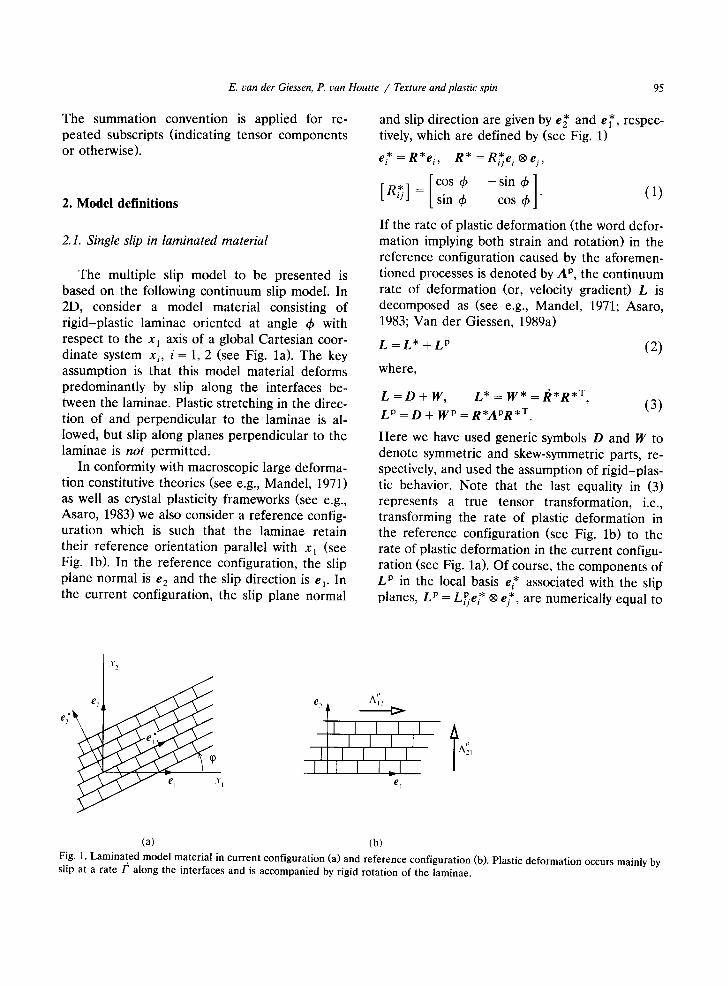
The multiple slip model to be presented is based on the following continuum slip model. In 2D, consider a model material consisting of rigid-plastic laminae oriented at angle ~b with respect to the x~ axis of a global Cartesian coor- dinate system xi, i = 1, 2 (see Fig. la). The key assumption is that this model material deforms predominantly by slip along the interfaces be- tween the laminae. Plastic stretching in the direc- tion of and perpendicular to the laminae is al- lowed, but slip along planes perpendicular to the laminae is not permitted.
In conformity with macroscopic large deforma- tion constitutive theories (see e.g., Mandel, 1971) as well as crystal plasticity frameworks (see e.g., Asaro, 1983) we also consider a reference config- uration which is such that the laminae retain their reference orientation parallel with x 1 (see Fig. lb). In the reference configuration, the slip plane normal is e 2 and the slip direction is e v In the current configuration, the slip plane normal
and slip direction are given by e~' and e~', respec- tively, which are defined by (see Fig. 1)
e * = R * e i , R * = R * e i ® e j ,
= [cos ~b - s in q~ ] [R~] /sin 6 cos 6 " (1)
If the rate of plastic deformation (the word defor- mation implying both strain and rotation) in the reference configuration caused by the aforemen- tioned processes is denoted by A p, the continuum rate of deformation (or, velocity gradient) L is decomposed as (see e.g., Mandel, 1971; Asaro, 1983; Van der Giessen, 1989a)
L = L* + L p (2)
where,
L = D + W , L * = W * = R * R *T ' (3)
L p = D + W p = R*APR *T.
Here we have used generic symbols D and W to denote symmetric and skew-symmetric parts, re- spectively, and used the assumption of rigid-plas- tic behavior. Note that the last equality in (3) represents a true tensor transformation, i.e., transforming the rate of plastic deformation in the reference configuration (see Fig. lb) to the rate of plastic deformation in the current configu- ration (see Fig. la). Of course, the components of L p in the local basis e* associated with the slip planes, L p - P * e*, are -- L i je i ® numerically equal to
X 2
e~' e~ ~ ~ A~
e I
(a) (b) Fig. 1. Laminated model material in current configuration (a) and reference configuration (b). Plastic deformation occurs mainly by
slip at a rate /a along the interfaces and is accompanied by rigid rotation of the laminae.
96 E. van der Giessen, P. t,an Houtte / Texture and plastic spin
the components of A p = A~.e i ® ei, i.e., L~. = A~. According to (1), W* represents the unknown rigid body spin of the laminae given by
W * = W i * e i ® e ], W I ~ = - W ~ = - d ) , (4)
and W p = Wi~e i ® ej is the plastic spin induced by the slip process.
Let this laminated material be subjected to an arbitrary (plane strain type) 2D deformation pro- cess, characterized by the components,
[ D,1 D,2 + W,2], [ L i j ] = [ j , 2 - W12 022 ] (5)
of L with respect to e i. The normal components are taken to be subject to the side condition D1j +D22 = 0 since slip is a volume preserving deformation mode and it is assumed that the other plastic deformation processes are also iso- choric. According to (2) and (3), the plastic rate of deformation A p that is necessary to accommo- date an applied deformation rate L is then given by
A p = R * T L R * - R*T/~ * . (6)
Recalling that shear deformation can occur only by slip along the laminae interfaces and referring to Fig. lb, the component AP2 of A p with respect to ei is readily interpreted as the slip rate F in the reference configuration, while we must fur- thermore impose the constraint
a p, -= 0 (7)
on the orthogonal components. Introducing this kinematic constraint in (6), it is concluded that q~ must satisfy
q~ = - 1 (Dl l - D 2 2 ) sin 2& +DI2 cos 24) - W12.
(8)
This differential equation determines the evolu- tion of the orientation of the laminae from an initial orientation q~ during the deformation pro- cess.
The slip rate is then obtained as
/ ~ - A~' 2 = - ( D l l -D22 ) sin 24) + 2Dl2 cos 24), (9)
and the (nonvanishing component of the) induced plastic spin is given by
W,P2 = ½1'= - ½( D , , - D22 ) sin 24)
+ D12 cos 205. (10)
It is noted that, in general, normal plastic strain rates given by
Ap 1 _AP2 = 1 = ~(Dl l -D22 ) cos 24) +D12 sin 24)
are necessary to accommodate the applied rate of deformation. Only for a particular orientation q) is it possible that plastic deformation occurs only by single slip. The physical mechanism that is responsible for these strain rates will not be iden- tified further.
Dafalias (1984) was the first to analyse the kinematics of this model material for the case of applied simple shear specified by Dll = D22 = 0, D12 = 14112 = ";,/2 in Eqs. (5-10). He also sug- gested the visualisation as a deck of cards. In particular he discussed the plastic spin during simple shear and the related orientation change
in relation with Mandel's (1971) macroscopic constitutive theory. Van der Giessen (1989c) showed the application of the PIOS theory in this particular case.
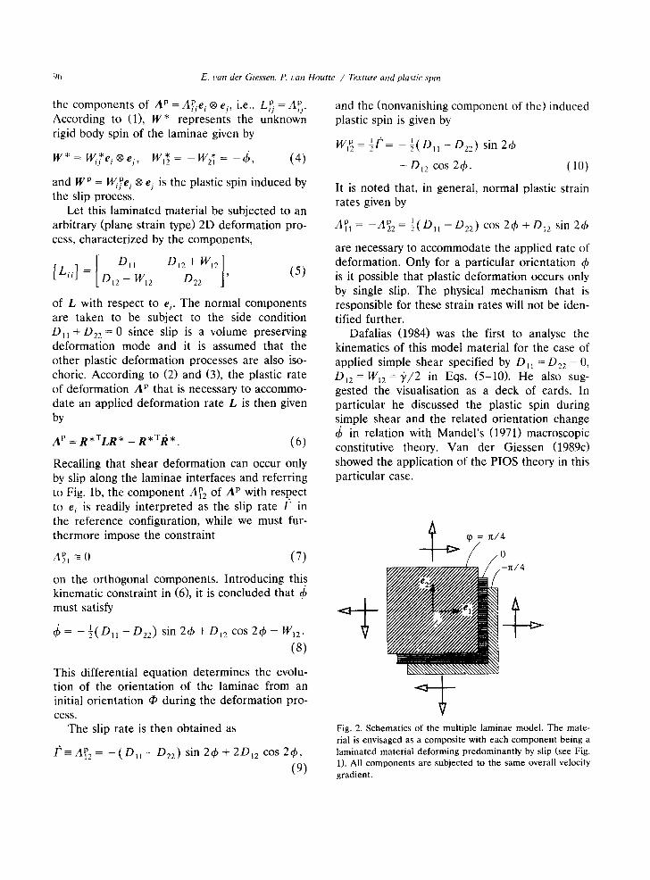
"2 Fig. 2. Schematics of the multiple laminae model. The mate- rial is envisaged as a composite with each component being a laminated material deforming predominantly by slip (see Fig. 1). All components are subjected to the same overall velocity gradient.
E. van der Giessen, P. van Houtte / Texture and plastic spin 97
2.2. Multiple laminae slip
Let us now consider an overlay or fraction type of model, in which each individual component (or fraction) is constituted by a laminated model ma- terial as discussed above (see Fig. 2). Deforma- tion of the composite model is assumed to be homogeneous in the sense that all components are assumed to be subjected to the same, i.e., applied overall deformation rate L, although they will all be differently oriented in general. This is analogous to the Taylor assumption in polycrystal models as will be discussed in Section 3.
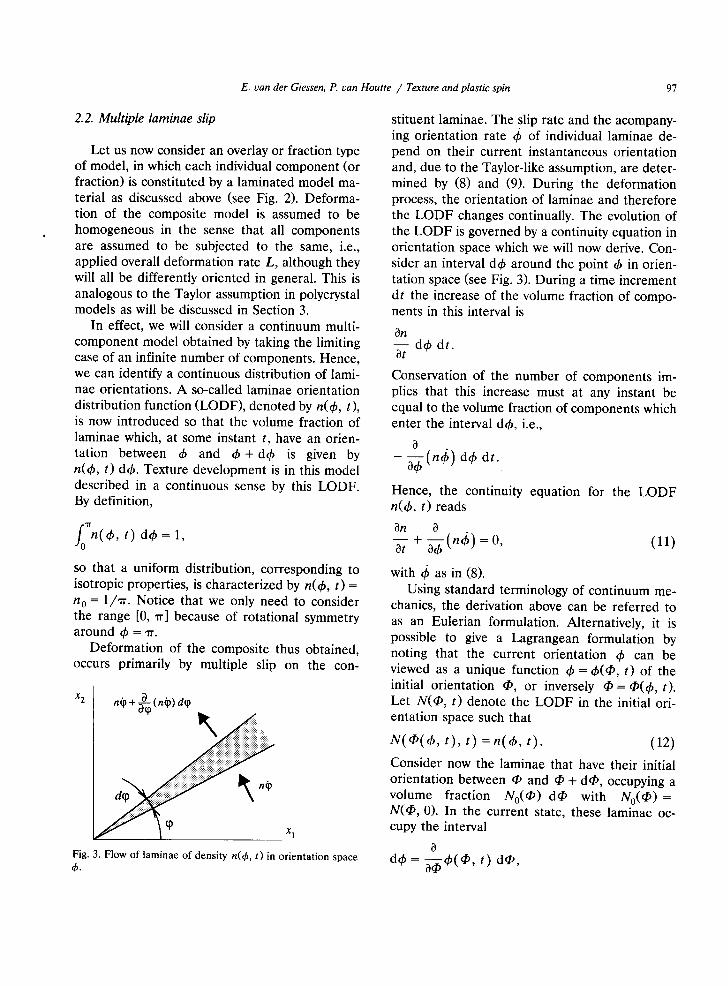
In effect, we will consider a continuum multi- component model obtained by taking the limiting case of an infinite number of components. Hence, we can identify a continuous distribution of lami- nae orientations. A so-called laminae orientation distribution function (LODF), denoted by n(&, t), is now introduced so that the volume fraction of laminae which, at some instant t, have an orien- tation between & and & + d& is given by n(~b, t) d&. Texture development is in this model described in a continuous sense by this LODF. By definition,
f0"~n(&, t) dth = 1,
so that a uniform distribution, corresponding to isotropic properties, is characterized by n(~b, t) = n o = 1/'rr. Notice that we only need to consider the range [0, rr] because of rotational symmetry around ~b = ~.
Deformation of the composite thus obtained, occurs primarily by multiple slip on the con-
x 2 nip + ~--~ (nip) dq~
x 1
Fig. 3. Flow of laminae of density n(&, t) in orientation space ,~.
stituent laminae. The slip rate and the acompany- ing orientation rate q~ of individual laminae de- pend on their current instantaneous orientation and, due to the Taylor-like assumption, are deter- mined by (8) and (9). During the deformation process, the orientation of laminae and therefore the LODF changes continually. The evolution of the LODF is governed by a continuity equation in orientation space which we will now derive. Con- sider an interval d~b around the point 4) in orien- tation space (see Fig. 3). During a time increment dt the increase of the volume fraction of compo- nents in this interval is
0n - - d & dt. at
Conservation of the number of components im- plies that this increase must at any instant be equal to the volume fraction of components which enter the interval d&, i.e.,
0 a6 (n4;) d6 dt.
Hence, the continuity equation for the LODF n(&, t) reads
On 0 - - + - - ( n t ~ ) = 0, (11) at a&
with 4~ as in (8). Using standard terminology of continuum me-
chanics, the derivation above can be referred to as an Eulerian formulation. Alternatively, it is possible to give a Lagrangean formulation by noting that the current orientation ~b can be viewed as a unique function & = &(q~, t) of the initial orientation 4 , or inversely q~ = q~(&, t). Let N(q~, t) denote the LODF in the initial ori- entation space such that
N ( ~ ( 6 , t ) , t) = n ( & , t ) . (12)
Consider now the laminae that have their initial orientation between q0 and q) + dq~, occupying a volume fraction N0(q~) dq~ with N0(q0 = N(q~, 0). In the current state, these laminae oc- cupy the interval
0 d6 = ~--~b(~, t) dqb,
98 E. can der Giessen, P. l~an Houtte / Texture and plastic spin
around d~ = 4'(q', t) and their density is given by N d~b. Conservation of number of components can now be simply expressed as
N = N O ~-~ , (13)
thus giving an immediate "state" equation for N(@, t). Of course, the Eulerian and Lagrangean approaches in (11) and (13), respectively, are equivalent; this can be readily shown by time differentation of (13), using (12) to relate the t ime derivatives of N and n. This confrontation emphasizes the difference between the time derivatives O/Ot and ( ) appearing in (11): On~at is the partial derivative of n(&, t) while 4; is the partial derivative of ~b((b, t) (cf., spatial and ma- terial time derivatives in the mechanics of con- tinua).
We now proceed by specifying the macroscopic plastic spin. Mandel (1982) showed that the macroscopic plastic spin of a polycrystalline ag- gregate may be determined as a volume average over the plastic spins of the constituent grains (see also Section 3). Here we apply a similar procedure to our multicomponent material and define the macroscopic plastic spin component by
WI~ = fcfWlP(d ~, t)n(ch, t) db , (14)
as the weighted average of the plastic spin W~P(4,, t) in individual components as given by (10). Other components of the macroscopic plas- tic spin tensor are irrelevant for this 2D model• A similar definition of the macroscopic spin W~ based on (4) leads to the relationship
w = ~ * + ~ p , (15) which is fully similar to the decomposition put forward in phenomenological constitutive theo- ries of the Mandel (1971) type.
It is appropriate to point out here that the definitions (14) and (15) provide in fact a kine- matic definition of a macroscopic substructure in the multicomponent material. For each compo- nent (or slip system), the triad {e*} is the natural candidate to define its substructure; but, to de- fine on the basis of this, some kind of macro- scopic substructure is not trivial, as discussed by
Mandel (1982) for polycrystalline materials. In- stead, he suggested to define the macroscopic substructure in a kinematic way: the macroscopic substructure is a triad of vectors that rotates with a spin equal to the volume average of the spin of the individual laminae orientations. With the Taylor-like assumption discussed above that all components are subjected to the same applied spin W, this is precisely what is implied by the spin WI* defined through (14) and (15).
2.3. Solution for stationary plastic flow
The basic governing equations for the problem at hand are expression (14) for the macroscopic plastic spin along with (10), either (11) or (13) for the LODF, and the evolution relation (8) for 4~. In this section we shall present analytical, closed-form solutions of the problem for the case of stationary flow, i.e., the applied velocity gradi- ent, Eq. (5), is constant in time. For conveniency, we introduce a time-like parameter r by
~" = W 1 2 t , (16)
and deformation rate parameters g and ~ through
1 Dlx-D22 D12 E - 2 Wi2 , " y - WI 2 . (17)
Henceforth, any time dependence is taken to be described in terms of r. The evolution relation (8) for ~( r ) can now be rewritten as
d4, d ~ - f ( b ) ' (18)
with the function f being defined by
f (&) = g sin 24, --~ cos 24, + 1. (19)
Expression (10) for the plastic spin Wlr~(ch) is written similarly as
- - ( 4 ' ) = 1 - f ( 6 ) . (20) WI2
Before turning to the actual solution of (18), it is possible to draw some general conclusions for the LODF, by noting that this solution will be of the form
F(&) = F(q~) -~-, (21)
E. can der Giessen, P. uan Houtte / Texture and plastic spin 99
with the (unknown) function F satisfying F'(~b) = 1/f(~b). Here, as before, q~ is the initial value of ~b at ~- = 0. Formally, the function ~b(q~, ~') to be used in applying (13) is obtained by solving (21) for ~b. Straightforward differentiation with respect to q~ then gives
0~b F'(q~) f(~b)
Oq~ F'(¢5) f(qb) '
which can be immediately substituted into (13) to yield
U(q~, ~-) = N0( tb ) f ( th (@, ~.)), (22)
or, after substitution for (b = (b(4,, ~-),
n(~b, ~-) = N0(q~(4~ , ~-)) (23) f(~b)
It is a straightforward matter to check that this solution (23) satisfies the differential equation (11) by using (18) and noting from (21) that Oq~(4~, ~')/0~" =f(q~). Thus we have obtained the general expression for the LODF once the solu- tion of q~ = q~(~b, ~-) has been established; this will be our next step.
In the Appendix, the solution of (18) in terms of the function F is given. The solution for q~ as a function of 4~ and ~" is then obtained from (21) after straightforward but lengthy algebra. Intro- ducing the parameter p by
P = ¢g2 + 332 = ¢ ( 12 Dzl - D22W12 W12
(24)
the final solution for the LODF for an initial isotropic material, so that N 0 ( q 0 = n 0 = 1/rr, reads
~'2(1 -- tanh2(7)
tanh2srr(1 + p sin 2qt)2+ ( r _ p tanh sr~ " cos 2 ~ ) 2 '
n withs r = ~ - I if p2>1,
no ~2(1 + tan2~ ")
tan2(r(1 + p sin 2~)2+ ( ~ - p tan ~- cos 2 ~ ) 2 '
with ~= ~ if p2 < 1,
(25a, b)
where qr is defined by
= ~b + 0 /2 , 0 = ATAN2( -- 9 , ~ ) . 1 (26)
The solution for cases where the initial LODF is not uniform can be derived along the same lines, but requires N o to be additionally specified and expressed in terms of ~b using the solution (b(tb, ~-) given in the Appendix.
The parameter p is undefined when W12 = 0. Nevertheless, a careful limiting procedure shows that the solution (25) is still valid, as will be demonstrated in Section 4.1.
It is shown in the Appendix how the two branches of the solution (25) can be trffnslated into each other by a simple substitution. In the sequel, we shall use this property to proceed by presenting results for the branch p2> 1, since this branch seems to be the most relevant one for practical applications, with the understanding that the results corresponding to the other branch are implicit under the mentioned substitution.
It is of particular importance to investigate the extrema of n(~b, t), since they will indicate the "preferred directions" in the material induced by the deformation. In effect, in studying simple shear it was suggested by Van der Giessen (1989c) to directly relate the PIOS directors to the maxi- mum and minimum value of n(~b, t) found in that case. Straightforward analysis of (25) reveals that, also in general, n(~b, t) has one maximum and one minimum value in the range [0, rr]. The extrema occur for the two values qrl, 2 ~ [ - ~r, at] for which
tanh ~'r tan 2~1, 2 -
is satisfied and attain the extremum values
nl,2 ~'2(1 - tanh2~'~-)
rto (¢sr 2 + tanh2sr,r _T_ ¢~" 2 + 1 t a n h ~',r) 2 '
(27)
1 ATAN2(y, x) is the Fortran arctan function defined on the interval [ - w , w] through y =sin(ATAN2) and x = cos(ATAN2).
100 E. can der Giessen, P. can Houtte / Texture and plastic spin
where the - sign in the denominator corre- sponds to the maximum value n~ and the + sign to the minimum value n 2. With (26) the extremal orientations ~ ,2 are found as
¢t.2 = ½arctan( " ~ ' - ~ tanh ( r ) 1 g~'+ ~ tanh ~r + ~kv, (28)
with k such that Chl,2 ~ [0, w]. Closer examina- tion of the expressions (27) and (28) reveals the following important properties of the LODF for an initially isotropic material subjected to station- ary plastic flow: (1) the extrema of the LODF occur at orthogonal
orientations, i.e., I qS~ - ~D 2 ] : 7 / 2 ; (2) the extremum values of the LODF are recip-
rocal, i.e.,
It is noted that the orthogonality property is similar to that of the (principal) directions of the eigenvectors of a symmetric second-order tensor in 2D. In addition, the reciprocity property is similar to the property of the principal values of, amongst others, the left stretch tensor V in the case of isochoric 2D deformations (V is the sym- metric part of the deformation gradient F). Therefore it is tempting to seek for a connection between the LODF extrema and principal values of known tensorial strain measures. As will be shown in Section 4.1, such a connection can in- deed be established for the class of deformation processes for which p 2 > 1.
We proceed by considering the macroscopic plastic spin, focussing again on the branch p2 > 1. The integral obtained from (15) after substitution of (20) and our result (25a) is rather involved; but it turns out that it can be evaluated in closed-form by using complex variables as described in the Appendix. The final result reads
(1 + ~" 2 ) tanh2~-r ~ l t ~ ~-2 + tanh2~-~. ' if pz > 1, (29a)
W12 (1 - - f f 2 ) tan2~,r ~2 + tan2~. ' if p2 < 1. (29b)
A final point worth discussing is the macro- scopic spin WI~ which can now be immediately derived from (15). This spin component repre- sents the average spin of the constituing laminae, and thus is a measure of the rate of rotation of the macroscopic substructure, as discussed above. An alternative measure of this would be the rate of rotation of the extrema of the LODF (note that the latter is a meaningful quantity only be- cause of the orthogonality property). After carry- ing out the time differentiation of expression (28) for the extremum orientations &l,:, one finds the identity
WI~ = - 2q;,,: (30)
in a macroscopic sense. Equation (4) is the corre- sponding relation on the micro level. Thus for any deformation process, the average spin of the laminae in this continuum model is twice that of the extremal orientations of the LODF.
3. The Taylor model
3.1. Introduction
The Taylor model for polycrystals attempts to simulate the plastic deformation of a polycrystal on the basis of the physical laws that govern the 3D plastic deformation of the individual crystal- lites of which the polycrystalline aggregate con- sists. The material is not treated as a continuum but as a set of m crystallites. The orientation of a crystal is usually characterized by the set g of the three Euler angles for the crystallographic axes with respect to the global reference frame x i.
The basic assumptions are: (i) The velocity gradient L is homogeneous
within a particular crystallite. It varies only with a long wavelength, much larger than the grain size; for most practical calculations, it is assumed equal in all m crystallites.
(ii) Within a particular crystallite with orienta- tion g, plastic deformation is taking place solely by multiple sli.p on crystallographic slip systems.
(iii) With F s denoting the slip rate on slip system s, the rate of plastic work per unit volume
E. van der Giessen, P. van Houtte / Texture and plastic spin 101
is I /~ l r ft. Here, ~.c is a material constant: the critical resolved shear stress on slip system s.
Assumption (i) is only an approximation. There are other theories that make different assump- tions concerning the distribution of stresses and strains over the crystallites. They will not be discussed here.
The Taylor theory also adopts a fourth as- sumption which will be discussed in the next section.
3.2. Solution o f the Taylor theory
The problem to be solved is: given a velocity gradient L and the orientations of the crystal- lites, what then are the slip rates/~s for each slip system.
We will treat here only the case of cubic crys- tals and introduce for each crystallite a local coordinate system x~ with associated base vec- tors e c which coincide with the [100] directions. Let n be the number of possible slip systems for a crystallite. Further, let n s be the unit vector nor- mal to the slip plane and b s the unit vector in the slip direction (s = 1 . . . . , n). The components of these vectors in the crystal reference system x7 are independent of the crystallite orientation.
Let K s be the rate of deformation tensor that describes the effect of a unit slip rate on slip system s, assuming that the crystal reference sys- tem does not rotate:
K~ = bs ® n s, ( n o s u m ) .
Let M s and Os, respectively, be the symmetric and skew-symmetric parts of K s. The components of K s (s = 1 , . . . , n ) with respect to the crystal reference system can be calculated once and for all for a given set of slip systems, e.g., {111}(110) for FCC crystallites or {110}(111)+ {112}(111) for BCC crystallites (n = 12 or 24, respectively). The rate of deformation associated with a set of slip rates /~ for one crystallite is now given by
L = L * + L p, (31)
which must be equal to the imposed velocity gradient. Here, L p = / ~ K , is the plastic rate of
deformation of one crystal, while L* = W* stands for the rate of rotation of the crystal lattice. Note that the expression (31) is identical to Eq. (2) in the continuum model.
The symmetric part of (31) can be written as
D =/~M~, (32)
and, in a given frame of reference, this consti- tutes six linear equations with n unknowns/~,. Of these six equations, one is dependent on the five others because of incompressibility, tr D = tr M s = 0. So, (32) represents only 5 independent equa- tions for each crystallite; but for FCC and BCC metals, n > 5, so there is an infinite number of solutions.
Taylor (1938) proposed to retain the solution which minimizes the internally dissipated power:
l/~, I~ "c = min. (33)
Equations (32) and (33) can then be solved, e.g., by means of linear programming (Van Houtte, 1988). A solution then typically has the form of five nonzero values /~ for the active slip systems and n - 5 that are zero. Condition (33) is the fourth assumption of the Taylor theory.
The Bishop-Hill theory is an alternative method to solve the same problem. It adopts assumptions (i) and (ii), but not assumptions (iii) and (iv). Instead, it uses the generalized Schmid law to construct a yield locus for a particular crystallite and invokes the maximum work princi- ple to find the stress that corresponds to an imposed strain-rate D. This allows for the deter- mination of the active slip systems (five in princi- ple) and (32) can be solved. The Taylor theory and the Bishop-Hill theory both lead to the same solutions. In fact, it can be demonstrated that both theories are mathematically equivalent (Van Houtte, 1988).
Unfortunately, the solution is often not unique. In such cases additional assumptions must be made in order to select one solution or a particu- lar combination of solutions. Many assumptions have been put forward for this. Some of these are based on physical considerations (e.g., influence of strain-rate sensitivity), others are purely statis-
1<12 E. can der Giessen, P. can Houtte / Texture and plastic spin
tical in nature (Van Houtte, 1988). In every case, a final solution is found that consists of the values of the n slip rates /~s.
Once the slip rates are known, the plastic spin of a crystallite can be calculated as the skew-sym- metric part of L p, W p = / 4 s ~ s ( s = 1 . . . . . r t ) . For a
particular applied velocity gradient L, the plastic spin W p depends on the crystal orientation g. This follows immediately from (32) when this relation is expressed with respect to the crystal reference system x~. Then the components of M+ are independent of g, but those of D are not. Hence, the solution for/~+ and, as a consequence, W* and W p will depend on g. After a large strain, most crystallites will rotate to orientations for which the crystal lattice spin W * = 0. This means that the crystal lattices do not rotate any more at ongoing deformation. For such so-called final orientations, the crystallite's plastic spin equals the applied spin W.
Consider now the entire polycrystal consisting of m crystallites and denote quantities dealing with the k th crystallite by a subscripted k. The first assumption of the Taylor-Bishop-Hil l the- ory suggests the introduction of a plastic rate of deformation for the polycrystal, i, P, as a weighted average of the contributions of all crystallites. The average plastic spin of the polycrystal is then found as
"representative slip system" as if the crystallite would possess only one slip system of the type described in Fig. 1. The orientations of such slip systems could then be used to construct a 2D "projection" of the CODF on the x l - x 2 plane. It seemed reasonable to choose the representative slip system at each step of the incremental proce- dure as follows: (i) it should coincide with one of the actual slip systems of the crystailite and (ii) among those, it should be the single one that can achieve the prescribed velocity gradient L as good as possible. The second criterion is judged by minimizing the "angle" 6 between the im- posed velocity gradient L and the velocity gradi- ent K s caused by a unit slip on slip system s when these tensors are represented as vectors in a 9-dimensional vector space, i.e.,
L: K s cos 6 = L ~ . . L v , ~ , (no sum),
where ":" denotes the scalar product of two ten- sors. Since the value of the denominator is inde- pendent of s, it is easy to see that the minimum of 6 coincides with the maximum of the so-called resolved slip rate /<s r on slip system s
" r , (no sum). F s - L : K s = b s ' L ' n s
W P = VkW~,-- V = ~ V k ( k = l , . . . , m ) , (34) V k
where V k is the weight factor for crystal k. The macroscopic plastic spin WP can be inde-
pendently calculated by the Taylor model and by the 2D multiple slip model, and can therefore be compared directly without further complications. This is not so for the LODF predicted by the 2D model and the 3D crystallite orientation distribu- tion function (CODF) according to the Taylor theory, since they have quite different definitions. However, it was desirable to compare these two anyway, in order to make a qualitative assessment about the value of the LODF predictions. The method we have chosen to use for this purpose, is to identify for each crystallite the orientation of a
So, for each crystal we select the slip system with the maximum absolute value of/~s r (note that this is not equal to the actual slip rate /~s on the considered slip systems as calculated by the Tay- lor program) and the 2D CODF, denoted by N, is then obtained by plotting a histogram of the inclination of the selected slip plane in the x l - x 2 plane, properly normalized by the total number of crystals m. Note that such a representation is symmetric with respect to rotations of 180 ° around the x 3 axis, just like the LODF of the multiple slip model. The CODF is plotted using 30 orien- tation intervals within the range [0,-rr] and is normalized by the uniform distribution N~ = 1/w. This 2D CODF representation clearly cannot capture many of the fine details of the actual 3D CODF, but is convenient for the present purpose of comparing relatively gross effects.
E. van der Giessen, P. van Houtte / Texture and plastic spin 103
4. Results
In this section we shall consider the texture and plastic spin predictions of the multiple lami- nae slip model for a number of stationary plastic flow processes, as specified by a constant velocity gradient. The results will be compared with nu- merical simulations using the Taylor polycrystal model discussed in Section 3 using an aggregate consisting of m = 294 crystallites. The initial ori- entations of the crystallites are chosen such that a uniform coverage of Eulerian orientation space is achieved so that the aggregate represents an isotropic material (see e.g., Van Hout te and Aernoudt, 1976). All simulations to be presented have used a time step At such that Aee = ~eAt = 0.05/V~-, where ~ is the applied effective strain rate defined by
~e = f~- tr D 2 .
In Section 4.1 we will consider a class of defor- mation processes involving simultaneous simple shear and biaxial stretching of a rolling-deforma- tion type, such that the parameter p 2 > 1. After presenting results for pure simple shear and pure roiling, followed by their combination, we shall derive some important general properties for this class of processes. Moreover, it will be shown that these propert ies hold for any stationary deforma- tion process with p 2 > 1. In Section 4.2 we will then discuss one particular process with 0 2 < 1 and we will conclude with a brief study of the effect of previous deformations through initial textures.
4.1. Rolling-shear deformations
4.1.1. Kinematics Let us consider a class of deformation pro-
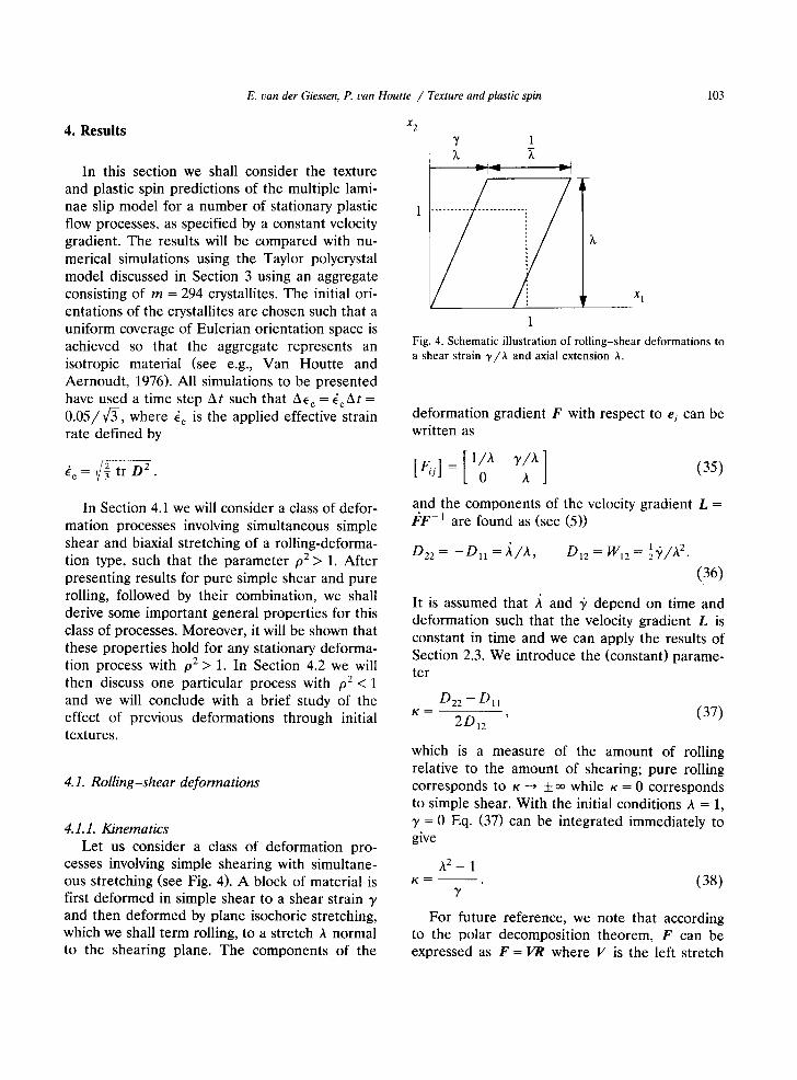
cesses involving simple shearing with simultane- ous stretching (see Fig. 4). A block of material is first deformed in simple shear to a shear strain 3' and then deformed by plane isochoric stretching, which we shall term rolling, to a stretch A normal to the shearing plane. The components of the
X 2 v_ 1
1 "'" I~ "
X 1
1 Fig. 4. Schematic illustration of rolling-shear deformations to a shear strain 3,/A and axial extension A.
deformation gradient F with respect to e i can be written as
and the components of the velocity gradient L = F F - t are found as (see (5))
D22 = - D I 1 = ,~ /A, D12 WI2 ~ T / A .
(36)
It is assumed that ,~ and ~ depend on time and deformation such that the velocity gradient L is constant in time and we can apply the results of Section 2.3. We introduce the (constant) parame- ter
D22 -- Dll K 2D12 (37)
which is a measure of the amount of rolling relative to the amount of shearing; pure rolling corresponds to K ---, _+ oo while K = 0 corresponds to simple shear. With the initial conditions A = 1, y = 0 Eq. (37) can be integrated immediately to give
A 2 - 1 K - - - (38)
3'
For future reference, we note that according to the polar decomposition theorem, F can be expressed as F = VR where V is the left stretch
104 E. van der Giessen, P. van Houtte / Texture and plastic spin
tensor and R is the rotation tensor, which can be written in terms of components as
r i [ coso sin°] RiJ = - - s i n a cos a '
with
y tan a . (39) h2+ 1
Further, it may be shown that the stretches hi, 2, or eigenvalues of V, are
1 1 [~(a2q - 1)2+T2 hi a 2 2a
principal
+ ~ ( h 2 - 1)2 + 72] , (40)
and that the corresponding principal directions are t%2 with
X~ = ~ arctan 1 + 7 2 - - h 4 ' (41)
and X2 = X1 + 'rr/2. From (17) it is now immediately clear that for
this deformation process the parameters for the analytical solution of the multiple laminae slip model take the values g = - K and ~ = 1, so that p2 = 1 + K 2 > 1 and ~" = K in Eq. (25)and subse- quent expressions. Furthermore, it follows that the variable s~r in these expressions becomes ~'r = (,i./A)t; since the stretching rate ,~/A is by definition constant, this may readily be integrated to give ~'r = In A. Making use of Eq. (38) for K, we can now express the solutions (25a) and (29a) for the LODF and the macroscopic plastic spin, respectively, entirely in terms of the current stretch A and the current shear 7. The expression for the LODF is rather unwieldy and will not be given here explicitly; the macroscopic plastic spin is found to be given by the simple expression
1t2] (42)
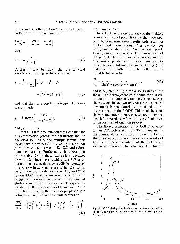
4.1.2. Simple shear In order to assess the accuracy of the multiple
laminae slip model predictions we shall now pro- ceed by comparing these results with results of Taylor model simulations. First we consider purely simple shear, i.e., h = 1 so that p = 1. Hence, simple shear represents a limiting case of the general solution discussed previously and the expressions specific for this case must be ob- tained by a careful limiting process letting ~" -~ 0 and 0 ~ - 7 / 2 with p--* 1. The LODF is then found to be given by
n 1
no sin 2& + (cos & - y sin 4Q 2' (43)
and is depicted in Fig. 5 for various values of the shear. The development of a nonuniform distri- bution of the laminae with increasing shear is clearly seen. In fact we observe a strong texture developing in the material as indicated by the distinct peak in the LODF. This peak becomes sharper and larger at increasing shear, and gradu- ally shifts towards ~h = 0, which is the final orien- tation for this deformation process.
The 2D representation of the CODF obtained for an FCC polycrystal from Taylor analyses in the manner described above is shown in Fig. 6. Broadly speaking the tendencies in the results of Figs. 5 and 6 are similar, but the details are somewhat different. One observes that, for the
5 7 = 2
4
3
2
0 I I I
45 90 135 180
(deg.)
Fig. 5. LODF during simple shear for various values of the shear 7, the material is taken to be initially isotropic, i.e.,
N / N o = 1.
E. van der Giessen, P. van Houtte / Texture and plastic spin 105
same shear, the peak in the CODF in Fig. 6 is sharper than the peak in the LODF and at the same time is significantly closer to the ideal ori- entation. Now, it is well known that the Tayior model tends to predict textures that are sharper than experimentally determined shear textures (see e.g., Gil-Sevillano et al., 1975), but the differ- ence in sharpness between Figs. 5 and 6 is consid- erably larger. The observed offset of the LODF peak indicates that the multiple slip model is not capable of resolving an accurate deformation tex- ture; but, it should be kept in mind that the purpose of that simple model is only to account for relatively gross effects. Moreover, it must be recalled that the CODF in Fig. 6 is nothing but a particular projection of the actual 3D CODF and that a comparison between LODF and CODF must be viewed with due restraint.
It is interesting to note here that Harren and Asaro (1989) have studied texture development during simple shear using an inherently 2D poly- crystal model. Indeed, using a finite element model of a polycrystalline aggregate, they ob- tained textures that are noticeably more diffuse than the Taylor model texture. A qualitative com- parison of the LODF of Fig. 5 with their 2D CODF's shows a reasonable agreement, with a slightly better agreement with the finite element model textures than with the Taylor predictions.
15
j 7 =2
10
0 45 90 135 180
(deg.)
Fig. 6. CODF for an FCC polycrystal during simple shear according to the Taylor model; the dashed line represents a uniform CODF.
cq
1.00
0.75
0.50
0.25
0.00 0
B C C ~ -
/ / /
/ /
/ /
i
2
Fig. 7. Macroscopic plastic
. . . . multiple slip m o d a l
T a y l o r m o d e l
i h i
4 6 8 10
7 spin during simple shear according
to the multiple laminae slip model and according to the Taylor model.
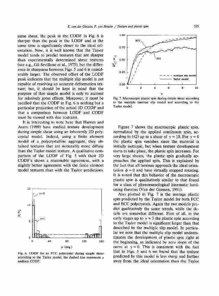
Figure 7 shows the macroscopic plastic spin, normalized by the applied continuum spin, ac- cording to (42) up to a shear of 3' = 10. For 3' = 0 the plastic spin vanishes since the material is initially isotropic, but when texture development starts to take place, the plastic spin increases. For very large shears, the plastic spin gradually ap- proaches the applied spin. This is explained by the fact that all laminae approach the ideal orien- tation g~ -- 0 and have virtually stopped rotating. It is noted that this behavior of the macroscopic plastic spin is qualitatively similar to that found for a class of phenomenological kinematic hard- ening theories (Van der Giessen, 1991).
Also plotted in Fig. 7 is the average plastic spin predicted by the Taylor model for both FCC and BCC polycrystals. Again the two models pre- dict qualitatively the same trends, while the de- tails are somewhat different. First of all, in the early stages up to 3' --- 3 the plastic spin according to the Taylor model is significant larger than that described by the multiple slip model. In particu- lar we note that the multiple slip model underes- timates the development of plastic spin right at the beginning, as indicated by zero slope of the curve at 3' = 0. This is consistent with the fact that in Figs. 5 and 6 we found that the texture predicted by this model is less sharp and further away from the ideal orientation than the Taylor
10b E. t'an der Giessen, P. tan Houtte / Texture and plastic spin
model texture. A second noteworthy point relat- ing to the Taylor model plastic spin is that for shears up to y ~ 1, the macroscopic plastic spin in FCC and BCC polycrystals is virtually the same, but for larger shears the development is quite different. This is due to the fact that for BCC most crystallites eventually reach final crys- tal orientations. For FCC materials, such a situa- tion is not reached (according to the Taylor model). The orientation of some crystallites at- tain stable loops in orientation space and they never stop rotating. For this reason, the plastic spin does not reach its limiting value W u.
Some remarks related to the jagged appear- ance of the average plastic results in Fig. 7 and further seem appropriate here. As discussed in the foregoing, the macroscopic plastic spin during the deformation process according to the Taylor polycrystal theory is calculated from (34) using a straightforward incremental procedure. It has also been mentioned that the plastic spin of each crystallite depends on its current orientation g, which is taken to be constant during the time increment At. It should then be realized that after each increment, a finite change A g of the crystallite's orientation has occured which may result in a finite change of the slip rates on the active slip systems and, furthermore, in an abrupt change in the set of slip systems that are active. Hence, the plastic spin may change discontinu- ously during the incremental process, as clearly seen in Fig. 7, but the error involved can be reduced by reducing the time step. However, even when At --, 0, discontinuous changes of W p may still occur due to discrete changes of the set of active slip systems; this phenomenon will dis- appear when the number of crystallites consid- ered in the computation is increased.
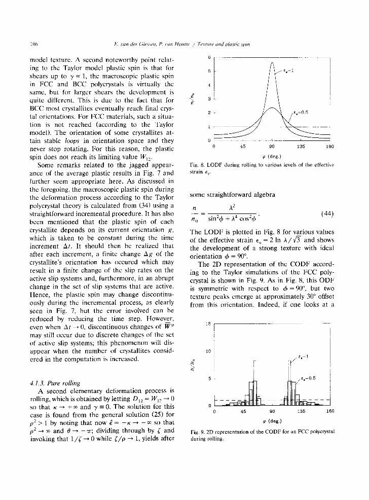
4.1.3. Pure rolling A second elementary deformation process is
rolling, which is obtained by letting Dl2 = WI2 ~ 0 SO that K ~ + ~ and y = 0. The solution for this case is found from the general solution (25) for p2> 1 by noting that now g = - K ~ - ~ so that p2_._> oo and 0 ~ - ~ ; dividing through by ~" and invoking that 1 / ( ---, 0 while #/p ~ 1, yields after
5 ~,= i
4
2
I. . . . .
0 h i i '
45 90 135 180
(deg.)
Fig. 8. L O D F d u r i n g r o l l i n g to v a r i o u s l eve l s o f t he e f f ec t i ve
s t r a in E e.
some straightforward algebra
n A 2
n 0 - sin2~b + A 4 cosZ4~ " (44)
The L O D F is plotted in Fig. 8 for various values of the effective strain E e = 2 In A / f 3 - and shows the development of a strong texture with ideal orientation (b = 90 °.
The 2D representation of the C O D F accord- ing to the Taylor simulations of the FCC poly- crystal is shown in Fig. 9. As in Fig. 8, this ODF is symmetric with respect to (h = 90 °, but two texture peaks emerge at approximately 30 ° offset from this orientation. Indeed, if one looks at a
15
i0
0 45 9o 135 ia0
(deg.)
Fig. 9. 2D representation of the CODF for an FCC polycrystal during roiling.
E. uan der Giessen, P. uan Houtte / Texture and plastic spin 107
typical {111} pole figure of the orientation distri- bution of slip plane normals for a cold rolled FCC metal, two strong maxima are observed at 35 ° from the compression axis (here, the x~ axis) and at 55 ° from the elongation axis (here, the x 2 axis). These are the strongest peaks associated with the final crystallographic texture and corre- spond to the two maxima in Fig. 9. The underly- ing reason for this double extremum is that, in any orientation, a cubic crystal possesses multiple possible slip systems. This feature is absent in the simple multiple slip model, which therefore pre- dicts only one texture peak.
It follows immediately from the general ex- pression (29) that the macroscopic plastic spin vanishes exactly, as expected for this process. In the Taylor analyses the average plastic spin does not vanish, but I WlO2/D22 ] remained smaller than 10-t0 for FCC and even smaller for BCC.
4.1.4. Combined rolling and simple shear Finally we now consider deformation processes
with simultaneous rolling and simple shear, as specified by K. Figure 10 shows the LODFs at two levels of the effective strain E e for cases with K = 0.5 or K = 2. The texture peak for K = 2 is slightly sharper than for K = 0.5; this tendency of increasing sharpness of the texture with increas- ing value of K becomes more and more pro- nounced at larger shears, giving peak values
5 ~ ~=0.5
! / 2 / /
1 / / /
0 I I I
45 90 135 180
(deg.)
Fig. 10. LODF during combined rolling and simple shear of an intially isotropic material for various values of the effective s t r a i n ee"
1.00 Jc=5
0 .75
( , 0.50
%-
0.25 y ,/ / /
0.00 ' ' ,
,~=2 ;=0
0 i 2 3 4 5 6
7/X Fig. 11. Macroscopic plastic spin versus shear during com- bined roiling and simple shear of an initially isotropic material according to the multiple laminae slip model.
nl /n o = 16.5 and 27.2 for K = 0.5 and 2, respec- tively, at e e = 2.
The accompanying macroscopic plastic spin is shown in Fig. 11 as a function of the shear 7 / h (see Fig. 4). It is seen that the plastic spin for K = 0.5 deviates only slightly from the result for pure simple shear, K = 0. For increasing value of K, so that the contribution of rolling becomes increasingly important, the plastic spin develop- ment is strongly accelerated; for instance, a value of WlP//W12 = 0.95 is attained at y/A = 1.7 in the case of K = 5, while for simple shear (A = 1) it takes 7/A = 8.7 to reach that value. It should be noted here that by plotting the results as in Fig. 11 the effect of simultaneous roiling is empha- sized; if the macroscopic plastic spin is plotted against the effective strain, the results for K = 2 and K = 5 are almost indistinguishable. The mar- coscopic plastic spin predicted by the Taylor model is depicted in Fig. 12. Comparing with Fig. 11 it is seen that the effect of simultaneous rolling on plastic spin is captured well by the multiple laminae slip model. In fact the agreement with Taylor model simulations appears to increase with increasing K. Regarding the Taylor simulations themselves, it is interesting to note that the aver- age plastic spin in the FCC polycrystal tends to oscillate violently at large values of K (sometimes, W1Pz/W12 > 1 so that the average lattice spin be- comes negative). Furthermore, it is seen from this
1(18 E. t,an der Giessen, P. can Houtte / Texture and plastic spin
1.00
0.75
0.25
IIH - ~cc !
o . o o [ , , : 0 I 2 3 4 5
7/x
Fig. 12. Macroscopic plastic spin versus shear during com- bined rolling and simple shear according to the Taylor model.
figure along with Fig. 7 that the difference be- tween FCC and BCC plastic spins decreases with increasing K.
In the cases considered so far, the parameter K was taken to be positive, i.e., rolling was consid- ered in the x 2 direction. It is of interest to consider also cases where rolling occurs in the x~ direction by taking K < 0. It turns out now that the macroscopic plastic spin according to the multiple laminae slip model is insensitive to the sign of K; this is immediately clear from the general expression (29) along with the definition (24) of p. More precisely, it follows from (42) that
1.00
0.V5 " I / # I,c1=o.5 0.50
0.25
Iit d . . . . ,,>o
o o o g , , , - - ~-- '~<~ 0 1 2 3 4 5
7/x Fig. 13. Macroscopic plastic spin versus shear according to the Taylor model during combined rolling and simple shear, with rolling in x 2 direction (K > 0) or in x I direction (K < 0).
for a given shear y / A , the plastic spin in the case of rolling to a stretch A in the x 2 direction is identical to that for rolling to A in the x I direc- tion (i.e., 1/A in x 2 direction). Hence, the plastic spin results in Fig. 11 are also valid for the corresponding opposite values of K. This particu- lar property of the solution is verified by repeat- ing the Taylor analyses of Fig. 12 for the opposite values of K and the results are shown in Fig. 13. It is seen that in some regressive (not point-wise) sense, the average plastic spin in polycrystals is indeed invariant to the sign of K.
4.1.5. Special properties of the solution The results of the multiple laminae slip model
for the class of deformations (36) considered here appear to possess a number of very interesting properties:
(1) Upon specializing the results (27) and (28) for the present deformation processes, the ex- trema of the LODF are found to coincide with the principal values of the left Cauchy-Green tensor B = FF T = V 2. That is, the extremum val- ues coincide with the principal values of B,
n-2[ = 1 ] , n2 - A 2 , (45) F/0 V/0
with X 1 and ~2 given by (40), and the extremal orientations coincide with the principal directions of B (and V),
01,2 = X1,2, (46)
given in (41). Hence, according to this simple multiple slip model, there is an immediate corre- lation between the main characteristics of the texture in terms of the LODF extrema and the deformation of the continuum in terms of B. It may be noted that this property implies that the extrema of the LODF rotate at a rate equal to the Euler spin (cf., Hill, 1978).
(2) The average laminae spin WI~ = W12 - WLr~ based on the expression (42) for the macroscopic plastic spin for this class of deformations turns out to be identical to the continuum rate of
rotation £212,
WI~ = ~'~ 12, (47)
E. van der Giessen, P. van Houtte / Texture and plastic spin 109
defined by O =/t,R T in terms of the rotation tensor R, which is in this case given by (39).
4.1.6. Concluding remarks It turns out that the foregoing properties have
a rather wide area of validity: Lemma: The properties of LODF extrema and
macroscopic plastic spin according to Eqs. (45), (46) and (47) are valid for any stationary flow process for which p2 > 1.
The proof consists of showing that for any (isochoric) stationary 2D flow process there exists a time independent orthogonal coordinate trans- formation such that the velocity gradient in the rotated coordinate system can be described by the components (36) for combined rolling-shear- ing, provided that the condition p2> 1 from (24) is satisfied. Applying such a coordinate transfor- mation to the general 2D velocity gradient in (5) (with the side condition Dll + D22 = 0) it follows by comparison with (36) that a necessary and sufficient condition for the existence of a map- ping to the rolling-shearing process is
½(Dll -D22 ) sin 2~b -D12 cos 2~b + W12 = 0.
This is equivalent to
p sin(2tb + 0) + 1 = 0,
with p and 0 defined in (24) and the second equality in (26), a condition which can only be satisfied if pZ > 1.
4.2. Rolling with superimposed spinning
The class of deformation processes considered in the previous section involved the branch p2 > 1 of the solutions (25) and (29). This branch, for which the stretching part of the velocity gradient dominates over the spin 14,'12, is clearly the more relevant of the two branches for applications. Nevertheless, for completeness, we shall consider in this section a class of deformation processes for which p2 < 1.
Consider a plane rolling process as above, with a superimposed rigid-body spin at an angular
1.00
0.75 \ 0.50 9'
0.25 = ~ ~ " 0.00
1 2
Ee
Fig. 14. Macroscopic plastic spin versus effective strain during rolling with superimposed rigid rotation of an initially isotropic material according to the multiple laminae slip model.
velocity &, i.e.,
D22 = - D I 1 = A / A , DI2 = 0,
W12=&, w h e r e & > A / A .
It is assumed that these velocity gradient compo- nents are constant in time and for a given stretch- ing the spin follows from & = (A/A)/p for any chosen value of p < 1. Upon integration, the an- gle of rotation is found as a = (In h)/p. The solution for the LODF and the plastic spin is now given by the second branch of the expressions (25) and (29), with g = - p , ~ = 0 so that 0 = rr, and where the quantity ~- is to be substituted by
~/1 _ p 2 ~ r - - - I n h.
P
Figure 14 shows the macroscopic plastic spin as a function of the current effective strain e e = 2 In A/x/3-. For p-~ 1 the deformation process tends to a simple shear process on 45 ° tilted planes at a shear rate 2 (A/A), so that the plastic spin result of Fig. 7 is recovered. For decreasing p, the plastic spin shows an oscillatory behavior with decreasing amplitude and increasing period- icity. This is due to the fact that with decreasing value of p, the material rotates at an increasing angular velocity. For this case, a fixed final orien- tation does not exist; instead, the texture rotates continually. The periodicity of the plastic spin is
110 E. can der Giessen, P. t~an Hout te / Texture and plastic ,spin
1.00
\
0.75
0.50
0.55
0.00
- - FCC
. . . . BCC
\
/ . / ~p=O.7g
1 2
~e Fig. 15. Macroscopic plastic spin versus effective strain during rolling With superimposed rigid rotation of an initially isotropic material according to the Taylor model.
directly connected with the rotational symmetry over 180 ° implied in the model.
The corresponding results of the Taylor analy- ses are shown in Fig. 15. It is seen from Fig. 14 that the multiple slip model captures the phe- nomena reasonably well in a qualitative manner, but quantitatively there are striking differences. Firstly, the multiple slip model plastic spin oscil- lates significantly slower; the effective strain "per iod" of the oscillations for the case p = 0.5 according to the Taylor simulations is approxi- mately 3 times smaller. Secondly, and in accor- dance with this, the maximum value of the plastic spin reached in the multiple slip model is larger. The physical reason for the fact that the variation of the plastic spin is underestimated by the multi- ple slip model is that each crystallite processes more slip systems than the ones that are at any instant active. Due to the dominant spin implied in this deformation process, the slip systems that are currently active will not be favorably oriented anymore after a short period of time (and strain). Thus, there is a relatively rapid change in active slip systems during the process; clearly this aspect of the actual crystallographic slip is not captured by the multiple slip model.
tribution. In many practical applications, some initial texture is present in the material due to processing. The influence of initial texture is of great importance and in particular when the prin- cipal directions of the subsequent deformation process are significantly different from the previ- ous deformations. In this section we shall briefly investigate the description of the influence of previous deformations on the plastic spin by con- sidering simple shear in the x l direction of a material which has previously been stretched (or rolled) to stretches A and 1/A in x 2 and x, directions, respectively.
The multiple slip model solution for the rolling process of an initially isotropic material has been discussed in Section 4.1; but for the second, sim- ple shear stage of the process the solution must be derived separately from the governing equa- tions (23) taking into account the initial texture produced by rolling. This texture N0(q~) to be used in (23) is given by Eq. (44) when the orienta- tion ~h in the latter is interpreted as the initial orientation @ for the subsequent simple shear process. Expressing then q~ in terms of the cur- rent orientation & at instant r during simple shear, as indicated in the Appendix, we finally obtain after lengthy algebra
n
no
A 2
sin2d, + A4(cos (i) - y sin q~)2'
It is interesting to compare this with Eq. (43) for simple shear of an initially isotropic material.
The macroscopic plastic spin during the simple shear process must now be calculated from (14) using the above result for the LODF. Following the same lines as in the general derivation stipu- lated in the Appendix, we ultimately find that the plastic spin at a shear y of a material which has been prestretched to A in the xe direction is given by
4.3. Influence of previous deformations
The cases considered in the previous subsec- tions related to an initially uniform laminae dis-
~1 p /~4y2 + (1 -- A 4)
W~2 ~472 + (1 + ~2) 2 '
E. van der Giessen, P. van Houtte / Texture and plastic spin 111
This is plotted in Fig. 16 for various values of the prestretch given in terms of the effective strain Ee = 2 In A/v~-. We observe that there is a dras- tic effect of the previously induced texture in the early stages up to shears of about 2; but the texture quickly evolves into a simple shear type texture and beyond 7 = 2 the plastic spin is roughly identical with that in an initially isotropic material. The fact that the plastic spin is negative initially is readily explained from the initial rolling texture, shown in Fig. 8: initially, the majority of laminae is oriented in the interval [45 °, 135 °] and when these are subjected to shear in the x 1 direction, rapid rotation (14;I > Wl2) of these laminae occurs in a clockwise direction (cf., Eq. (8)), so that as a consequence the average plastic spin adds up to a negative value.
Clearly, this is not representative for real crys- tals which have more than one slip system, as shown by the Taylor results in Fig. 17. We do observe that the memory of the previous rolling vanishes essentially after shears of about 2.5, although for very large shears, say 3' > 4, it ap- pears that the plastic spin is slightly larger for the larger initial deformations, as predicted also by the multiple slip model. However, the actual plas-
1.00
i 0.75 _ _ ~ L - - - - ~ - -
0.50 ~ ~
0 .25 c~
0.00 %-
- 0 . 2 5 / - - rotmag in z,-dJr,cUon
- 0 . 5 0
- 0 . 7 5
- 1 . 0 0 0 1 2 3 4 5
7
Fig. 16. M a c r o s c o p i c p las t ic spin d u r i n g simpie s h e a r o f a
m a t e r i a l t h a t has b e e n p r e d e f o r m e d by ro l l ing to a n effect ive
s t ra in ~e = 2 I n A / 1 / ~ (A is t he s t r e t ch in the x a d i rec t ion) ;
rolling in x I direction corresponds to taking ~c < 0.
1.00
ew
eq
0.75 e . = l ~ ,..~ f f ~ " " ~
o . 5 o
0.25
- - FCC . . . . BCC
0.00 ' ' ' '
0 1 2 3 4 5
7
Fig. 17. Macroscopic plastic spin according to Taylor analyses during simple shear of a polycrystal that has been prede- formed by rolling to an effective strain % (cf., Fig. 16).
tic spin during the early stages of simple shear is quite opposite to the multiple slip model's predic- tions, showing in fact a positive initial plastic spin. This is explained from the fact that starting from a roiling texture, subsequent shear will tend to activate other slip systems than those that were mainly active during rolling. Roughly put, the slip systems that will be activated in the first stages of shear will be "orthogonal" to the ones during rolling so as to give rise to a positive average plastic spin. In terms of the multiple slip model, this could be simulated by envisaging a second laminated composite which is rotated by 90 ° rela- tive to the original material and which is acti- vated during subsequent shearing instead. Due to symmetry of the multiple slip model, this alterna- tive texture can also be regarded to be the result of rolling to a stretch A in the x 1 direction, or 1/A in x 2 direction. The plastic spin during sim- ple shear in this alternative composite is shown in Fig. 16 by the dashed curves. Note that the initial plastic spin has the correct sign now; but, the dip in the Taylor model plastic spin predictions in Fig. 17 at 3' = 1 is still not captured.
5. Discussion
It is emphasized that the multiple laminae slip model presented here does not embody an alter- native to crystal plasticity theories. Instead, it
112 E. l~an der Giessen, P. t;an Houtte / Texture and plastic spin
should be regarded a model which attempts to bridge the gap between such physically based theories and phenomenological constitutive theo- ries, in so far as texture development and plastic spin are concerned. The model recognizes slip and slip-induced rotation as the key concepts for texture development and plastic spin, and incor- porates these into an admittedly simplistic contin- uum model. Evidently, the model can only be potentially capable of capturing gross effects of texture development but cannot describe details such as orientations of individual crystals, slip activity on actual slip systems, etc. It should be noted in this connection, that the relation be- tween crystallographic slip systems and the lami- nated components of the present model is not strict. One may tentatively identify each lami- nated component with a crystal slip system; but this implies that all slip systems would be active. Thus, the multiple slip model does not incorpo- rate a selection criterion for activating slip sys- tems like in the Taylor-Bishop-Hil l crystal plas- ticity models as discussed in Section 4 (see also e.g., Van Houtte and Aernoudt, 1976; Van Houtte, 1988), nor does it relate the laminae slip rate to a resolved shear stress as in rate sensitive Taylor models (e.g., Asaro, 1983; Harren and Asaro, 1989).
The multiple slip model has certain similarities with the approach of Clement (1982) in predict- ing 3D deformation textures in polycrystalline materials. In fact, the differential equation (12) for the LODF is fully analogous to the conserva- tion equation for the CODF proposed by Clement. The role of the orientation parameter d~ is taken over there by three Euler angles specify- ing the orientation of the crystallographic axes. The important difference is that Clement leaves the rate of rotation of the orientation to be specified additionally from either experimental data or physically based theoretical models, while the multiple slip model immediately specifies the corresponding d~ through (8) according to the assumptions discussed in Section 2.2.
Despite the enormous simplicity of the multi- ple slip model, it has been shown that for a class of processes of an initially isotropic material such that ,0 2 > 1, the macroscopic plastic spin and the
overall characteristics of texture, as obtained from detailed polycrystal simulations, are described with reasonable accuracy. This class of deforma- tion processes is characterized by the fact that according to (24) the strain-rates dominate over the imposed spin, and includes practically impor- tant processes such as rolling and simple shear. The cases where we have found insufficient cor- relation with the polycrystal predictions, namely rolling with superimposed spinning such that p2 < 1 and simple shear of a pre-rolled material, are characterized by a rapid rotation of the principal directions of strain-rate relative to the current texture. For the cases where p2 < 1, this means a rate of rotation relative to strain-rate which is greater than in simple shear; but such processes are not of great practical relevance. The basic underlying reason for the lack of correlation in the cases mentioned is the fact that a frequent change of the currently active slip systems occurs during these processes - something that cannot be represented by the multiple slip model.
A further limitation of the model is that it cannot distinguish between types of crystal struc- tures. However, although it is well-known that there are significant differences in the precise texture development in FCC and BCC polycrys- tals (see e.g., Van Houtte, 1986), we have ob- served here only marginal differences between the macroscopic plastic spin for the two crystal classes. In fact for the cases considered here, the largest difference was found during simple shear (see Fig. 6). The observation that the multiple slip model's predictions generally agree better with results for BCC than for FCC materials is due to the fact that BCC has more possible slip systems. This property is the motivation for the so-called pencil glide model for BCC crystal plas- ticity (as explained by Taylor (1955) when dis- cussing the behavior of iron), which is indeed conceptually akin to the multiple slip model.
At this point, it seems appropriate to recall the motivation for the present work as discussed in Section 1, namely the formulation of macroscopic constitutive theories for the description of large deformation plasticity of polycrystalline metals incorporating the effect of texture development. As mentioned there, a growing part of the cur-
E. can der Giessen, P. van Houtte / Texture and plastic spin 113
rent research in this area is based on the original work of Mandel (1971), who proposed to explic- itly incorporate the macroscopic substructure of the actual material into the continuum model in a phenomenological manner through the introduc- tion of a triad of vector directors (in a somewhat different setting, similar ideas were already brought forward by Besseling (1968)). The direc- tor triad would naturally serve as a frame of reference for the anisotropic material properties associated with its particular substructure. Here, the term "substructure" should be understood to be a phenomenological concept, which precise definition would depend on the material under consideration. Irrespective of that, the key fea- ture of Mandel's idea is to decouple the evolution of the substructure (director triad) from that of the continuum, thus leading to the concept of plastic spin being, roughly put, the difference between the continuum spin and that of the sub- structure. As a consequence, the plastic spin will generally play a key role in the constitutive laws for all substructure connected quantities, includ- ing observable variables such as stress and inter- nal variables. For instance, rate evolution rela- tions for Cauchy stress expressed in the current actual state appear naturally in terms of an objec- tive corotational rate involving the substructure's spin (see e.g., Mandel, 1971, 1982). As a further example, consider an orthotropic material, for which the director triad naturally serves to moni- tor the orientation of the orthotropic axes; the plastic spin then is the key parameter to monitor the rate of evolution of the orthotropic axes rela- tive to that of the continuum. For a recent thor- ough discussion on these matters, see e.g., Dafalias (1987).
Against this background, the present study has contributed to the development of the mentioned constitutive theories by providing an explicit, physically sound identification of this macro- scopic substructure in a polycrystaUine material due to crystallographic texture. It will be clear that this particular interpretation of the macro- scopic substructure neglects morphological tex- ture and other microscopic sources of the actual macroscopic substructure of the material, but this will usually be a fair approximation. In a certain
sense, the present results provide a mechanisti- cally deterministic explanation of the macro- scopic plastic spin associated with crystallo- graphic texture. Thus, they serve to complement the internal variable approaches found in the current literature - and perhaps to direct future work - where plastic spin is specified through a set of phenomenological constitutive equations in terms of internal variables (e.g., the back stress in kinematic hardening models; see e.g., Dafalias, 1983, 1984, 1985; Loret, 1983; Paulun and Pech- erski, 1987; Van der Giessen, 1989a, b). Work in which the present results are incorporated into a macroscopic constitutive theory accounting for texture development is currently in progress (e.g. Van der Giessen and Aifantis, 1992).
It should be noted though that the relevance of the plastic spin concept and the necessity for its constitutive description are still being debated in the recent literature (see e.g., Obata et al., 1990; Nemat-Nasser, 1990). However, this seems to be solely due to the fact that these authors do not explicitly define a substructure (or a director triad) embedded in the material, so that in fact their concept of plastic spin is sweepingly differ- ent from that appearing in Mandel's and related works as discussed above. Instead of such an explicit substructure, other implicit concepts are employed to monitor or define directions of anisotropy, such as the principal directions of the plastic stretch tensor (Nemat-Nasser, 1990), and the spin of these directions is used explicitly in the pertinent rate constitutive equations. So, in the authors' opinion, this latter approach is in many respects really an alternative to substruc- ture based theories; with such alternative imple- mentations of the concept of spinning of anisotropy directions, the present results seem to be equally relevant.
Acknowledgement
The work of EvdG was made possible by a fellowship of the Royal Netherlands Academy of Arts and Sciences.
114 E. can der Giessen. P. can Houtte / Texture and plastic spin
References
Asaro, R.J. (1983), Micromechanics of crystals and polycrys- tals, Adv. Appl. Mech. 23, 1.
Besseling, J.F. (1968), A thermodynamic approach to theol- ogy, in: H. Parkus, L.I. Sedov, eds., Proc. IUTAM Sympo- sium on Irreversible Aspects of Continuum Mechanics, Springer, Vienna, p. 16.
Clement, A. (1982), Prediction of deformation texture using a physical principle of conservation, Mater. Sci. Eng. 55, 203.
Dafalias, Y.F. (1983), Corotational rates for kinematic hard- ening at large plastic deformations, J. Appl. Mech. 50, 561.
Dafalias, Y.F. (1984), The plastic spin concept and a simple illustration of its role in finite plastic transformations, Mech. Mater. 3, 223.
Dafalias, Y.F. (1985), The plastic spin, J. Appl. Mech. 52, 865. Dafalias, Y.F. (1987). Issues on the constitutive formulation at
large elastoplastic deformations, Part 1: Kinematics, Acta Mech. 69, 119.
Dafalias, Y.F. and M.M. Rashid (1989), The effect of plastic spin on anisotropic material behavior, Int. J. Plast. 5, 227.
Gil-Sevillano, J., P. Van Houtte and E. Aernoudt (1975), Deutung der Schertexturen mit Hilfe der Taylor-Analyse, Z. Metallkd. 66, 367.
Harren, S.V. and R.J. Asaro (1989), Nonuniform deforma- tions in polycrystals and aspects of the validity of the Taylor model, J. Mech. Phys. Solids 37, 191.
Hill, R. (1978), Aspects of invariance in solid mechanics, Adv. Appl. Mech. 18, 1.
Loret, B. (1983), On the effects of plastic rotation in the finite deformation of anisotropic elastoplastic materials, Mech. Mater. 2, 287.
Mandel, J. (1971), Plasticit~ classique et viscoplasticit~, CISM Lecture Notes No. 97, Springer, Udine.
Mandel, J. (1982), D6finition d'un rep~re privil~gi~ pour l'~tude des transformations an~lastiques du polycrystal, J. M~c. Th~o. Appl. 1, 7.
Nemat-Nasser, S. (1990), Certain basic issues in finite-defor- mation continuum plasticity, Meccanica 25, 223.
Obata, M., Y. Goto and S. Matsuura (1990), Micromechanical consideration on the theory of elastoplasticity at finite deformations, Int. J. Eng. Sci. 28, 241.
Paulun, J.E. and R.B. Pecherski (1987), On the application of the plastic spin concept for the description of anisotropic hardening in finite deformation plasticity, Int. J. Plast. 3, 303.
Raniecki, B. and Z. Mrdz (1989), On the strain-induced anisotropy and texture in rigid-plastic solids, in: M. Kleiber, J. A. K6nig, eds., Inelastic Solids" and Structures, Pineridge Press, Swansea, p. 13.
Taylor, G.I. (1938), Plastic strain in metals, J. Inst. Met. 02, 307.
Taylor, G.I. (1955), Dislocations and plasticity, in: R. Gram- mel, ed., Deformation and Flow of Solids (Proc. IUTAM Colloq., Madrid), Springer, Berlin, p. 3.
Van der Giessen, E. (1989a), Continuum models of large deformation plasticity - Part I: Large deformation plastic- ity and the concept of a natural reference state, Eur. J. Mech. A / Solids 8, 15.
Van der Giessen, E. (1989b), Continuum models of large deformation plasticity - Part II: A kinematic hardening model and the concept of a plastically induced orienta- tional structure, Eur. J. Mech. A /So l ids 8, 89.
Van der Giessen, E. (1989c), On a continuum representation of deformation-induced anisotropy, in: J. Fan and S. Mu- rakami, eds., Advances in Constituti~,e Laws for Engineer- ing Materials', Pergamon Press, Beijing, p. 503.
Van der Giessen, E. (1990), A model of anisotropically hard- ening materials based upon the concept of a plastically induced orientational structure in: J.P. Boehler, ed., Yield- ing, Damage and Failure o f Anisotropic Solids, Mechanical Engineering Publisher, London, p. 187.
Van der Giessen, E. (1991), Micromechanical and thermody- namic aspects of the plastic spin, Int. J. Plast. 7, 365.
Van der Giessen, E. and E.C. Aifantis (1992), On the consti- tutive modelling of plastic spin due to texture development using scale invariance arguments, work in progress.
Van Houtte, P. (1986), The effect of strain path and texture, in: H.J. McQueen and J.P. Bailon, eds., Strength of Metals and Alloys (Proc. ICSMA 7, Montreal 1985), Vol. III, Pergamon Press, Toronto, p. 1701.
Van Houtte, P. (1988), A comprehensive mathematical formu- lation of an extended Taylor-Bishop-Hill model featuring relaxed constraints, the Renouard-Wintenberger theory and a strain rate sensitivity model, Textures Microstruct. 8 & 9, 313.
Van Houtte, P. and E. Aernoudt (1976), Considerations on the crystal and the strain symmetry in the calculation of deformation textures with the Taylor theory, Mater. Sei. Eng. 23, 11.
E. van der Giessen, P. van Houtte / Texture and plastic spin 115
A p p e n d i x
In this Appendix we list some of the detailed expressions involved in the analytical solutions for the LODF and the macroscopic plastic spin in Section 2.
With p defined by (24), the function F(~b) in the solution (21) of the differential equation (18) has two branches depending on the sign of p2 _ 1:
l 1 1 [ t a n q t + O - ~ 71n ~ ~+~+~ , with ; = ~/p2_ 1, if p2 > 1,
F(~5) = 1 ( tan ~ + p ~ (A1) arctan[ ~ ], w i t h ~ = ~ / 1 - p 2 , i f p 2 < l ,
where ~ is given by (26). These two functions can be simply connected to each other by allowing ~ and ~, as well as the mathematical functions entering in (A1), to be complex valued. For instance, the second relationship for p2 < 1 can be obtained from the first by noting that
( = i f (A2)
(i z = - 1 ) and substituting this for ~. This observation enables one to continue the analysis for, say, the case p2 > 1 and quickly transforming this to the case/)2 < 1 by substitution of (A2).
The function q~(~b, t) to be substituted into (23) can be obtained by solving (21) for ¢P with F according to (A1); the result is given by
tanh ( r + ( ( + p tanh ~'r) tan tanqt o= , i f p 2 > l , (A3)
~" - (p + tan ~ ) tanh ¢r
in terms of ~ defined by (26) and aP 0 defined similarly by ~0 = q~ + 0/2. As mentioned before, the result for p2 < 1 may be obtained by substitution of (A2).
Substitution of (19) and (20) along with the expression (25) for n(~b, t) into the definition (14) for the plastic spin, gives the following integral to be evaluated:
W12 = no~r2(tanh2srr - 1)
fo r:+O/2 p sin 2 ~
x /2 tanh2~%-(1 + p sin 2qt)2 + ( r _ p tanh ~'r cos 2 ~ ) 2 dqt
for p2 > 1. First it is noted that since the integrand is periodic with period 2~', the integral can be taken to run over [0, ~r]. Next we transform the integral into a real-valued contour integral along the unit circle in the complex plane by the substitution z = e 2iq', yielding
= no(2(tanh2~'r - 1)
1 - z 2 dz p.z × -~-~Op tanh (~'[i(1 - z2) tanh ~rz - (1 +z2)~'] + [st2 + (1 +p2) tanh2{r]z z
(A4)
This integral can now be conveniently evaluated using the residue theorem, giving due notice of the fact that (A4) refers to p2 > 1. After lengthy algebra, the simple result (29a) is obtained, and (29b) is derived by substitution of the transformation (A2).


![Analytical solutions for wall slip channel flows in porous ... EUROPEAN PHYSICAL JOURN… · Magneto-viscoelastic slip flow has been studied by Zheng et al. [39] with the fractional](https://img.pdfslide.net/doc/110x75/5f97b080e47761016913bd63/analytical-solutions-for-wall-slip-channel-flows-in-porous-european-physical.jpg)