Embed Size (px)
Citation preview
1
University of Maine Human Powered Submarine
Team Members:
Zachary Ferry Devon Gaudet Aaron Sutton
Christopher Walker
2
Human Powered Submarine Report 1. Overview 2. Design of Submarine and Prediction of Performance 1. Hull Fabrication 2. Propulsion 3. Control surface design 4. Solid modeling of the hull 5. Mathematical Model 3. Life Support System 1. Air Supply Size 1. Tank 2. Bailout Hose 2. Operator Harness 4. Controller 1. Purpose 2. Hardware
1. Basic Stamp Box 2. Power Control Box 3. Main Power Supply 4. Servo Junction Box 5. Power Switch / Data Link 6. Accelerometer 7. Joystick 8. Servos 9. Waterproof Connectors
3. Mounting the Control System 4. Programming 5. Safety 1. ISR Safety Overview 2. Changes to Initial Design 1. Windows in the Bow 2. Hatch Release Mechanism 3. Safety Buoy 6. Diving Guidelines 1. University of Maine Sub Diving Regulations 2. ISR Regulations 3. Additional Safety Measures 4. Procedures 1. Preparing the Sub for Water Entry 2. Operator Entry 3. Operator Exit 1. Standard Procedures 2. Emergency Procedures
3
7. Appendices 1. Overview The human powered submarine project at the University of Maine is now in its fifth year. Multiple year efforts have focused on the development of the hull, ergonomics, safety, optimization of the propulsion system and development of controllers for the autopilot and fly-by-wire system. Each year's team found it necessary to make evolutionary design changes to the submarine's components to improve performance and safety standards. Of primary concern in any diving event is the diver’s air supply. The submarine is designed to hold twin 19 ft3 air tanks. With 38ft3 of breathing air a diver should be able to breath for approximately 30 minutes under normal conditions and still have 500psi remaining in the tanks. During race conditions the diver’s air consumption is twice as much as normal so he will only have 15 minutes of dive time. We calculated 15 minutes of air will be sufficient of the race. The following are issues that were addressed and changed this year: 1) Due to the addition of a slalom course on the final day of racing, the submarine must now be maneuverable as well as fast. Our control surfaces are designed for maneuverability, but the original method of controlling the sub really wasn’t up to the task of the slalom course. The controls were not positioned in a comfortable way to enable the operator to make large control input commands. To rectify this situation, this year’s team decided to install a fly-by-wire/autopilot system. 2) The entrance/egress hatch also needed some revision to ensure that it could be removed quickly and completely in the event of an emergency. The hatch has had in-water testing and is safe and effective. 3) An additional viewing port has been added to the nose of the submarine to allow better visibility for the operator and for the safety divers observing the operator. 4) In-water training with the sub has taken place since the fall. Each session in the pool allowed the dive team to become more comfortable with the submarine’s behavior when submerged. While a full test of the submarine has not yet been completed, the individual systems have been tested submerged and deemed satisfactory. Notably, the safety buoy has been successfully deployed with the hull at various angles of pitch and roll. 2. Design of Submarine and Prediction of Performance The Human Powered Submarine at the University of Maine has been a multi-year project. The sections below summarize the work accomplished prior to 2005. The submarine will be competing this year for the first time in the history of the project. 2.1. Hull Fabrication The first hull shape we chose was a NACA 66-015. This shape can be approximated as a Rankine half-body. To determine the proper hull size the hull was scaled to fit around the submarine operator’s body and their necessary gear. The proposed hull shape was low drag but had significant limitations for a submarine hull. The primary problem with this design is the large internal area. The hull shape also has a high aspect ratio making it very long. This additional length increased the internal volume. Boundary layer separation is also an issue with this design. After investigating the hydrodynamic drag characteristics of the hull we determined that the
4
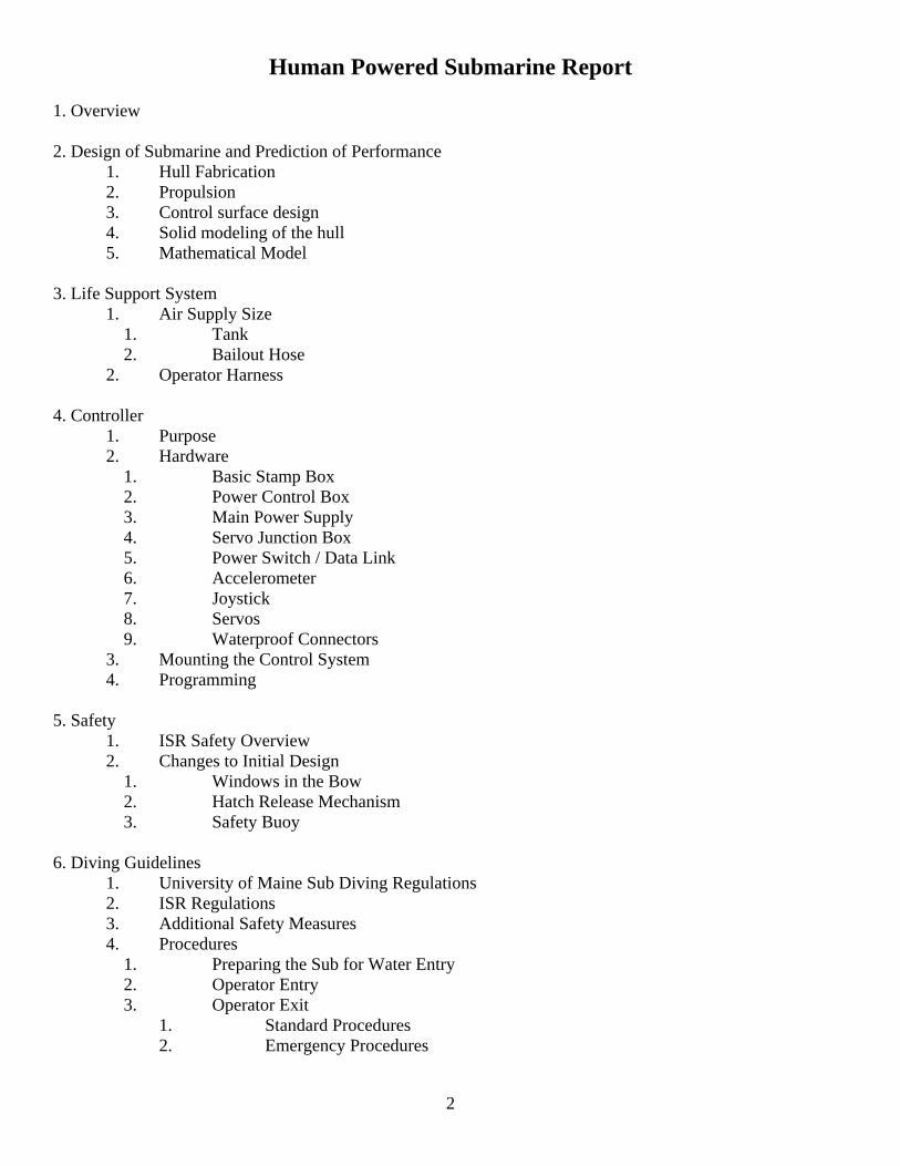
boundary layer would trip if the front of the hull forms a bull nose. Our research showed that a bull nosed shape would trip the boundary layer at the tip of the hull. The stagnation pressure is above the static pressure. The alternative design focused on minimal volume for the hull. The submarine operator was modeled in a 3-D computer model. The profile of the operator and the necessary support gear defines the minimal frontal area of the final design. Design for minimal volume was undertaken in the same fashion. The sub surrounds the operator and the gear. There also needs to be enough room for the operator to move while inside the hull. After experimenting with many shapes we found a hull with a weight of 1024 lbs in fresh water. From this basic shape the potential for boundary layer separation was minimized. A pointed nose was used to prevent tripping the boundary layer at the tip of the sub. The sub trailing edge was cut at 80% of the total length. By cutting off the tail of the sub we minimized the amount of stagnant water clinging to the tail of the sub. This cut also minimized the internal volume of the sub. Top Speed Calculations Submarine runs are made in a 100 foot fresh water tow basin. To calculate the maximum speed the definition of the drag coefficient (CD) was used:
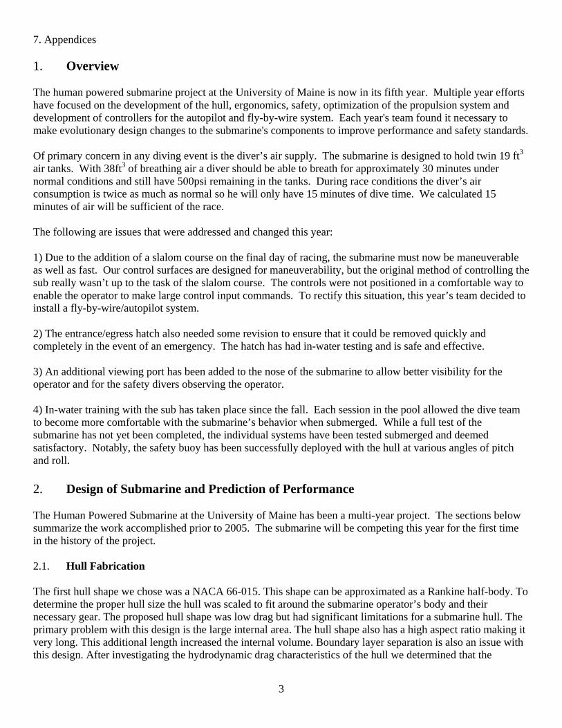
The frontal area of the submarine was calculated at 3.03 ft2 using a solid model of the submarine. The above equation was solved for velocity to yield:
The submarine will reach its maximum speed when the drag force is equal to the thrust force (T) that can be provided by the human pilot. To establish an estimate of the thrust force a small electric outboard motor was used. The motor was rated at 432 watts and provided 44 lbf of thrust. A drag coefficient of 0.15 was used for the initial estimates. This value is based on a revolved ellipsoid with a length similar to the height ratio as the submarine. The maximum speed that the submarine can reach was calculated to be 10.4 mph. To find out if a human providing the above thrust power can accelerate the water filled submarine to the maximum speed in the provided 170-foot acceleration distance. The top speed attainable now becomes a function of thrust, drag, mass and distance. A simple sum of the forces equation is used for this calculation.
5
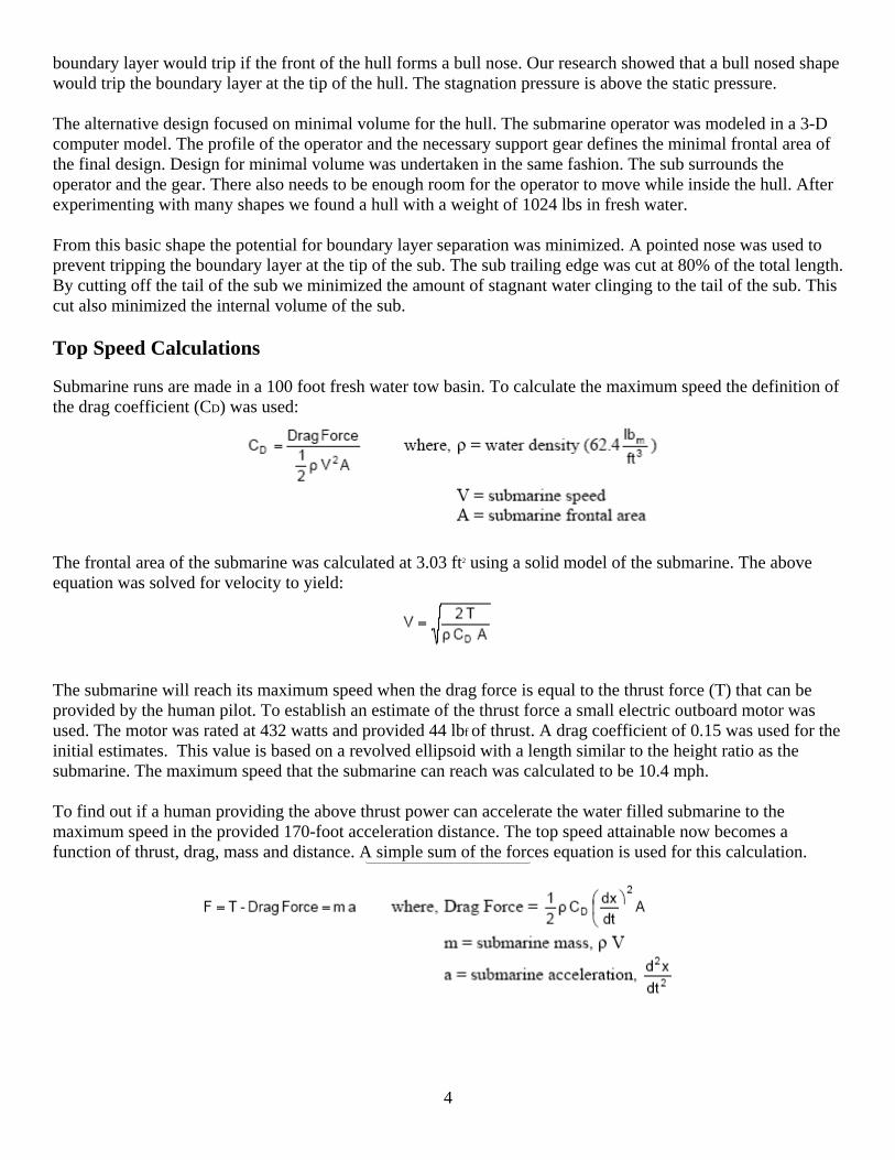
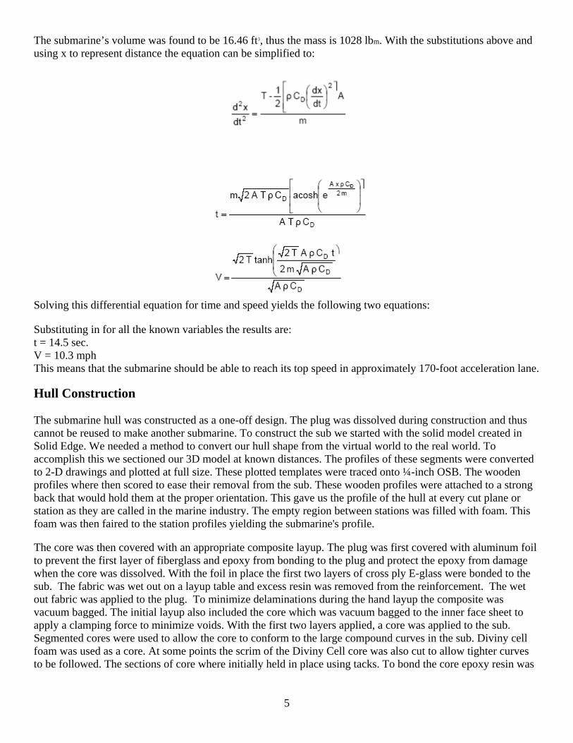
The submarine’s volume was found to be 16.46 ft3, thus the mass is 1028 lbm. With the substitutions above and using x to represent distance the equation can be simplified to:
Solving this differential equation for time and speed yields the following two equations: Substituting in for all the known variables the results are: t = 14.5 sec. V = 10.3 mph This means that the submarine should be able to reach its top speed in approximately 170-foot acceleration lane. Hull Construction The submarine hull was constructed as a one-off design. The plug was dissolved during construction and thus cannot be reused to make another submarine. To construct the sub we started with the solid model created in Solid Edge. We needed a method to convert our hull shape from the virtual world to the real world. To accomplish this we sectioned our 3D model at known distances. The profiles of these segments were converted to 2-D drawings and plotted at full size. These plotted templates were traced onto ¼-inch OSB. The wooden profiles where then scored to ease their removal from the sub. These wooden profiles were attached to a strong back that would hold them at the proper orientation. This gave us the profile of the hull at every cut plane or station as they are called in the marine industry. The empty region between stations was filled with foam. This foam was then faired to the station profiles yielding the submarine's profile. The core was then covered with an appropriate composite layup. The plug was first covered with aluminum foil to prevent the first layer of fiberglass and epoxy from bonding to the plug and protect the epoxy from damage when the core was dissolved. With the foil in place the first two layers of cross ply E-glass were bonded to the sub. The fabric was wet out on a layup table and excess resin was removed from the reinforcement. The wet out fabric was applied to the plug. To minimize delaminations during the hand layup the composite was vacuum bagged. The initial layup also included the core which was vacuum bagged to the inner face sheet to apply a clamping force to minimize voids. With the first two layers applied, a core was applied to the sub. Segmented cores were used to allow the core to conform to the large compound curves in the sub. Diviny cell foam was used as a core. At some points the scrim of the Diviny Cell core was also cut to allow tighter curves to be followed. The sections of core where initially held in place using tacks. To bond the core epoxy resin was
6
applied under the core sections. The sections were repined and the core was then vacuumed bagged to maintain the proper clamping pressure. Hard attachment points were also put into the hull at this point in the process. Foam cores typically require either the addition of metallic hard points or saturation of the core material with epoxy for attachment points. The pins were removed from the core after the epoxy cured. Finally the last two face sheets were bonded on top of the core. To finalize the hull construction we needed to fair the outer hydrodynamic surface of the hull. This was done using body filler. Syntactic foam could also be used instead of body filler. After the hull was faired we cut out the main hatch. The foam was dissolved in the hard to reach areas and cut out of the larger sections. 2.2. Propulsion System One of the main design challenges for the submarine was the development of an appropriate linkage to attach two of the Hobie Mirage drive systems. Each Mirage Drive has two input links, which move in opposite directions. The prototype connecting method connected the input links on each side of the Mirage Drives with a single connecting link. This formed a four-bar linkage. This method prevented smooth motion through the hydrofoil cycle, resulting in a rocking motion of the foil set. The prototype connecting link design consisted of bolts used to attach the connecting links to the input links, which rubbed against each other during a foil cycle. The second design problem was mounting the hydrofoil sets to the submarine hull while keeping the support completely fixed. The foam core and thin hull of the submarine requires that a large surface area be used for mounting. The drive system requires: • An appropriate design of connecting links between two hydrofoil sets • Fabrication of connecting links • Design of mounting and boundary conditions for hydrofoil system • Fabrication of mounting system • Test and installation of propulsion system A. Comprehension of Hobie MirageDrive Mechanics 1. 3-D Modeling. Given the complex function and geometry of the Hobie MirageDrive, a 3-D model was required to approach the problem. There were two objectives for modeling: 1) to visualize and understand the previous design problems and 2) to analyze and test the proposed design solutions. The starting point was to understand the Hobie MirageDrive mechanism. After determining the important parts that would affect the design, the Faro Arm Platinum Coordinate Mapping Machine (CMM) was used to get dimensions. These parts were modeled and the MirageDrive was assembled using Pro/ENGINEER. 2. Mechanism Analysis. The chains and cables were not modeled since version of Pro/ENGINEER doesn’t support cables or flexible parts. The MirageDrive has two sections with the top section consists of the fins and the fin axes – the bar the fins rotate about. This section is used to determine the force that the chains would exert on the wheel given an applied force on the fins. The bottom section consists of the support, the wheel, and the input links. The applied forces on the fins were estimated. MirageDrive Model
7
Thus, in order to mimic a full MirageDrive cycle, the fins were assumed to move from 0 to ± 87.5° and the input links were assumed to move from 0 to ± 40°. A total of four position drivers – per MirageDrive – were setup to provide the required range of motion. \ 3. The Pin Separation. The most important design parameter is the pin separation – which is the vertical distance between two MirageDrive pins. This parameter is critical since it has an effect on the submarine’s drag, design of connecting link, and the operator’s leg room. The first-pass design had a pin separation of 26 inches. In order to test this configuration, a boundary that represents the inside of hull was created to observe the behavior of the MirageDrives. This way, the design could be checked, for example, to see if the operator has enough leg room. A range of pin separations was tested and the design was qualitatively assessed. The final design has a pin separation of 24 inches which allows for full motion through a hydrofoil cycle, provides adequate leg room for the operator, and minimizes the drag. The choice of a pin separation of 24 inches also depended on the analysis described in the next section. Using the techniques of kinematic modeling the first length of a connecting link was graphically determined [6]. A part called the connector was created as a channeled bar. The animation of the mechanism was then started. An error showed up saying that there is not enough tolerance in the mechanism. Hence, the tolerance (i.e. the maximum allowed movement from the joints) was increased from 0.001 to 0.1 in. The animation ran, however, it was not smooth as the forces at the joints were high. With that being said, the cause of the unsmooth or “rocking” motion was detected; a constant length connecting link doesn’t work. This issue was investigated in detail to determine the required link length. In Pro/ENGINEER, a parameter called “Link Length” was set to measure the distance between the two pedal positions through the cycle. It was found that the required link length changes as a function of the pin separation through a cycle as shown in Figure 5. Hence, a new design with better understanding of the problem was proposed. The basic design of the new connecting link is similar to the old one; aluminum bars with channels to hold the MirageDrive input link. The new one, however, is wider to contain a rotating arm – that accounts for the required change in length – and has a nominal length obtained from the previous plot. This new mechanism creates a five-bar linkage. A 3-D model of the connecting link was built to test the design and determine if there are any toggle positions. It was also used to select the length of the channels, and the width of the links. Different types of standard bolts were tested to ensure that the links have enough clearance space to move. As mentioned earlier, it was important to attach the hydrofoils to the hull over the largest surface area possible. It was determined the best way to accomplish this was to build a frame inside the hull that would extend outside to hold the hydrofoils. The frame consists of two hoops, one at the front of the foil sets and one at the rear. Each hoop has a tab extending through the hull at the top and the bottom. A housing, which attaches to the tabs, surrounds each MirageDrive and supports it at the pins and end mounts. There are a total of eight housing pieces. Four housing pieces are rectangular in shape and have the function of holding the pins. The other four housing pieces are half-moon in shape and restrict the end mounts of the hydrofoils. Once a rough estimate of the inner profile of the hull was obtained, it was used to create a model of the hoops. The MirageDrives and the connecting links were positioned at the center of the hull. From there, drawings were created to determine the required length of the tabs.

8
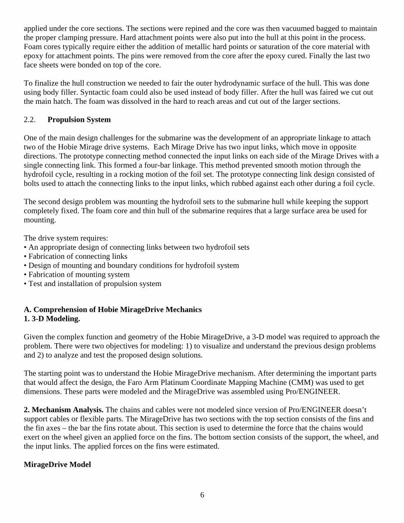
As a part of design analysis, the 3-D model was used for finite element analysis (FEA) with Pro/MECHANICA. The selected material for the connecting links is aluminum and no further analysis was performed. On the other hand, the material selection for the hoops needed more careful investigation. Our current analytical background was not sufficient to determine stresses and consequently material selection. Hence, FEA models of the hoops were used to help in the process. With the resources available, there were two options for hoop manufacture either chopped glass fiber or woven glass fiber fabric. A conservative estimate of the engineering properties of chopped fiber was used to would be to use the properties of the epoxy. The ultimate tensile strength of Fibre Glast Epoxy Resin 2000 with Hardener 2060 is 45,170 psi, which is not enough to withstand the estimated stresses on the hoop. Therefore, the chopped fiber hoop did not satisfy the design criteria. The other alternative was to over-design and use glass fiber with wood core. A first-pass analysis was performed by assuming the properties of white pine wood. The hoops seemed to withstand the applied load with much less deformation. A second pass involved using a very specific stacking sequence. The effective engineering properties of the fiber glass composite were estimated. These values were input into Pro/MECHANICA and further supported the design choice of glass fiber with a plywood core. 2.3. Control Surface Design The control surfaces were fabricated in the same way the hull was fabricated. There are four control surfaces on the aft end of the sub: top, bottom and both sides. See Appendix 2 for the control surface selection and layup. 2.4 Solid Modeling of the Hull The existing hull was not modeled in any CADD system when this year’s team picked up the project. In order to get an as-built model, the team borrowed optical measuring equipment from Sackett & Brake Land Surveying, Inc. This equipment is typically used for land surveying, which is done on a much larger scale than the submarine. The team was not sure how good the data would be when they started the project, but it was the only data that they had with which to generate a solid model of the submarine (see Figures 1 and 2).
Figures 1 and 2: The surveying equipment is shown here during the data collection phase of the modeling project.
9
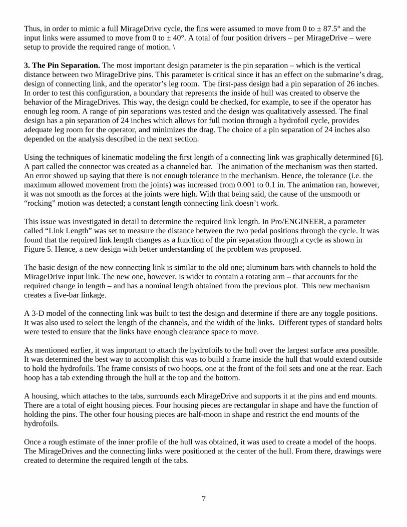
Figure 3:The SolidWorks model created from the data collected with the survey equipment.
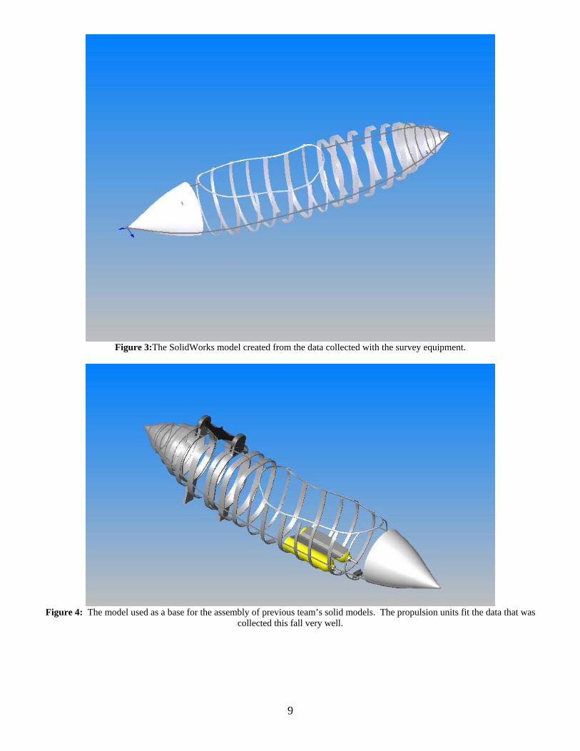
Figure 4: The model used as a base for the assembly of previous team’s solid models. The propulsion units fit the data that was
collected this fall very well.
10
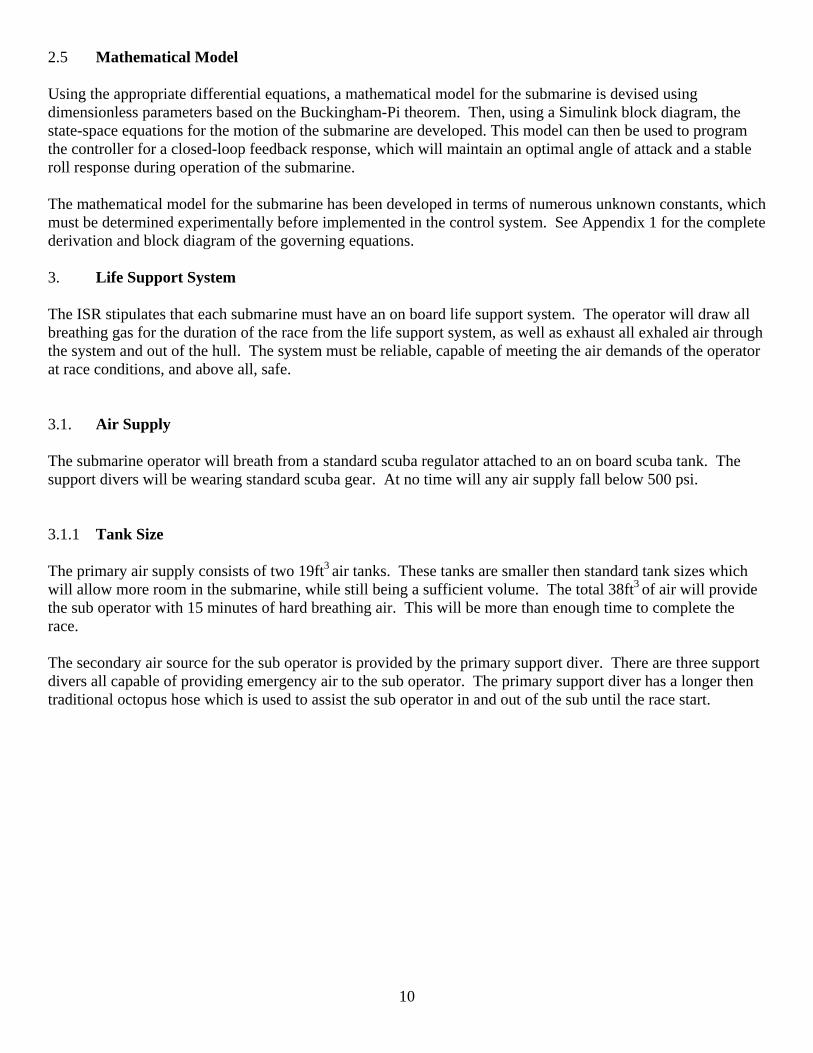
2.5 Mathematical Model Using the appropriate differential equations, a mathematical model for the submarine is devised using dimensionless parameters based on the Buckingham-Pi theorem. Then, using a Simulink block diagram, the state-space equations for the motion of the submarine are developed. This model can then be used to program the controller for a closed-loop feedback response, which will maintain an optimal angle of attack and a stable roll response during operation of the submarine. The mathematical model for the submarine has been developed in terms of numerous unknown constants, which must be determined experimentally before implemented in the control system. See Appendix 1 for the complete derivation and block diagram of the governing equations. 3. Life Support System The ISR stipulates that each submarine must have an on board life support system. The operator will draw all breathing gas for the duration of the race from the life support system, as well as exhaust all exhaled air through the system and out of the hull. The system must be reliable, capable of meeting the air demands of the operator at race conditions, and above all, safe. 3.1. Air Supply The submarine operator will breath from a standard scuba regulator attached to an on board scuba tank. The support divers will be wearing standard scuba gear. At no time will any air supply fall below 500 psi. 3.1.1 Tank Size The primary air supply consists of two 19ft3 air tanks. These tanks are smaller then standard tank sizes which will allow more room in the submarine, while still being a sufficient volume. The total 38ft3 of air will provide the sub operator with 15 minutes of hard breathing air. This will be more than enough time to complete the race. The secondary air source for the sub operator is provided by the primary support diver. There are three support divers all capable of providing emergency air to the sub operator. The primary support diver has a longer then traditional octopus hose which is used to assist the sub operator in and out of the sub until the race start.
11
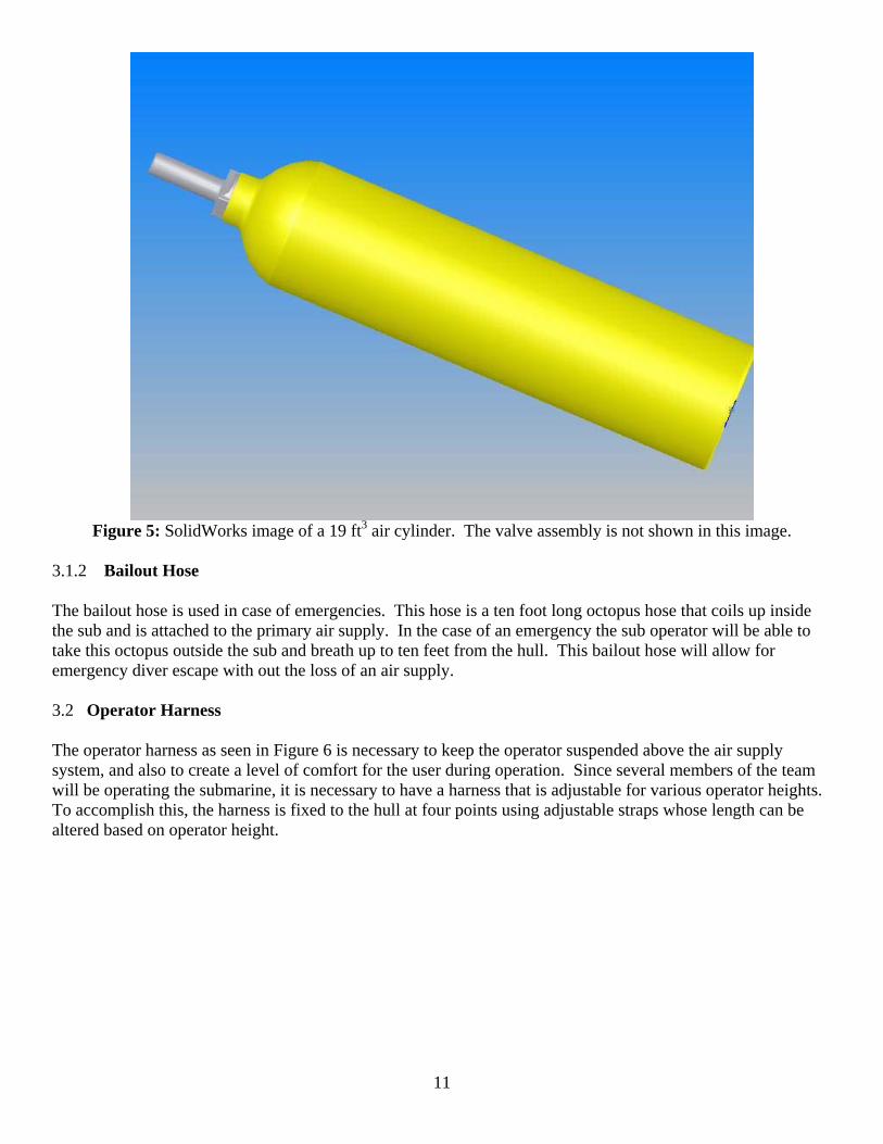
Figure 5: SolidWorks image of a 19 ft3 air cylinder. The valve assembly is not shown in this image.
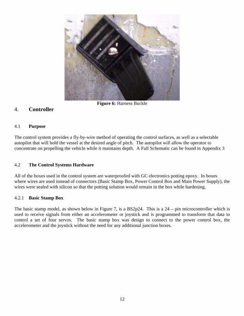
3.1.2 Bailout Hose The bailout hose is used in case of emergencies. This hose is a ten foot long octopus hose that coils up inside the sub and is attached to the primary air supply. In the case of an emergency the sub operator will be able to take this octopus outside the sub and breath up to ten feet from the hull. This bailout hose will allow for emergency diver escape with out the loss of an air supply. 3.2 Operator Harness The operator harness as seen in Figure 6 is necessary to keep the operator suspended above the air supply system, and also to create a level of comfort for the user during operation. Since several members of the team will be operating the submarine, it is necessary to have a harness that is adjustable for various operator heights. To accomplish this, the harness is fixed to the hull at four points using adjustable straps whose length can be altered based on operator height.
12
Figure 6: Harness Buckle
4. Controller 4.1 Purpose The control system provides a fly-by-wire method of operating the control surfaces, as well as a selectable autopilot that will hold the vessel at the desired angle of pitch. The autopilot will allow the operator to concentrate on propelling the vehicle while it maintains depth. A Full Schematic can be found in Appendix 3 4.2 The Control Systems Hardware All of the boxes used in the control system are waterproofed with GC electronics potting epoxy. In boxes where wires are used instead of connectors (Basic Stamp Box, Power Control Box and Main Power Supply), the wires were sealed with silicon so that the potting solution would remain in the box while hardening. 4.2.1 Basic Stamp Box The basic stamp model, as shown below in Figure 7, is a BS2p24. This is a 24 – pin microcontroller which is used to receive signals from either an accelerometer or joystick and is programmed to transform that data to control a set of four servos. The basic stamp box was design to connect to the power control box, the accelerometer and the joystick without the need for any additional junction boxes.
13
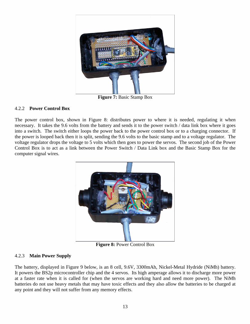
Figure 7: Basic Stamp Box
4.2.2 Power Control Box The power control box, shown in Figure 8: distributes power to where it is needed, regulating it when necessary. It takes the 9.6 volts from the battery and sends it to the power switch / data link box where it goes into a switch. The switch either loops the power back to the power control box or to a charging connector. If the power is looped back then it is split, sending the 9.6 volts to the basic stamp and to a voltage regulator. The voltage regulator drops the voltage to 5 volts which then goes to power the servos. The second job of the Power Control Box is to act as a link between the Power Switch / Data Link box and the Basic Stamp Box for the computer signal wires.
Figure 8: Power Control Box
4.2.3 Main Power Supply The battery, displayed in Figure 9 below, is an 8 cell, 9.6V, 3300mAh, Nickel-Metal Hydride (NiMh) battery. It powers the BS2p microcontroller chip and the 4 servos. Its high amperage allows it to discharge more power at a faster rate when it is called for (when the servos are working hard and need more power). The NiMh batteries do not use heavy metals that may have toxic effects and they also allow the batteries to be charged at any point and they will not suffer from any memory effects.
14
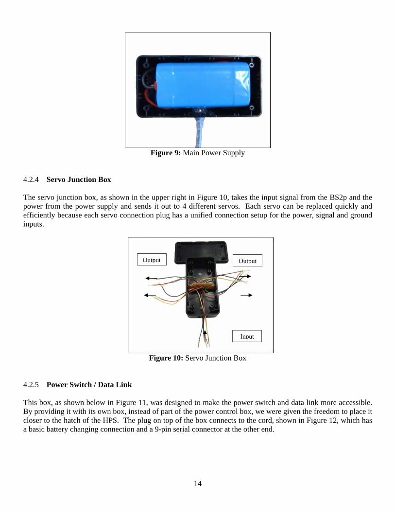
Figure 9: Main Power Supply
4.2.4 Servo Junction Box The servo junction box, as shown in the upper right in Figure 10, takes the input signal from the BS2p and the power from the power supply and sends it out to 4 different servos. Each servo can be replaced quickly and efficiently because each servo connection plug has a unified connection setup for the power, signal and ground inputs.
Figure 10: Servo Junction Box
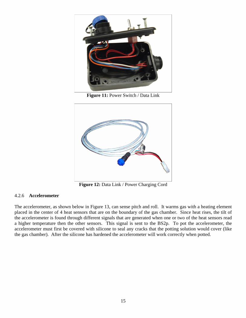
4.2.5 Power Switch / Data Link This box, as shown below in Figure 11, was designed to make the power switch and data link more accessible. By providing it with its own box, instead of part of the power control box, we were given the freedom to place it closer to the hatch of the HPS. The plug on top of the box connects to the cord, shown in Figure 12, which has a basic battery changing connection and a 9-pin serial connector at the other end.
Input
OutputOutput
15
Figure 11: Power Switch / Data Link
Figure 12: Data Link / Power Charging Cord
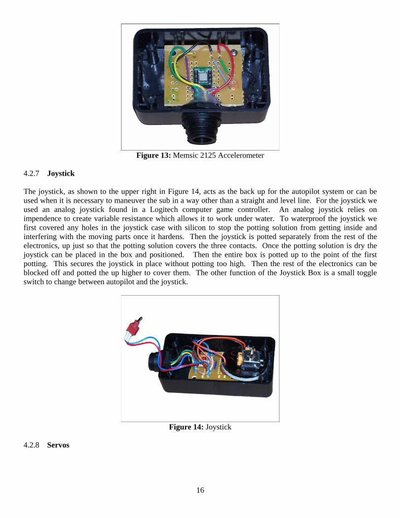
4.2.6 Accelerometer The accelerometer, as shown below in Figure 13, can sense pitch and roll. It warms gas with a heating element placed in the center of 4 heat sensors that are on the boundary of the gas chamber. Since heat rises, the tilt of the accelerometer is found through different signals that are generated when one or two of the heat sensors read a higher temperature then the other sensors. This signal is sent to the BS2p. To pot the accelerometer, the accelerometer must first be covered with silicone to seal any cracks that the potting solution would cover (like the gas chamber). After the silicone has hardened the accelerometer will work correctly when potted.
16
Figure 13: Memsic 2125 Accelerometer
4.2.7 Joystick The joystick, as shown to the upper right in Figure 14, acts as the back up for the autopilot system or can be used when it is necessary to maneuver the sub in a way other than a straight and level line. For the joystick we used an analog joystick found in a Logitech computer game controller. An analog joystick relies on impendence to create variable resistance which allows it to work under water. To waterproof the joystick we first covered any holes in the joystick case with silicon to stop the potting solution from getting inside and interfering with the moving parts once it hardens. Then the joystick is potted separately from the rest of the electronics, up just so that the potting solution covers the three contacts. Once the potting solution is dry the joystick can be placed in the box and positioned. Then the entire box is potted up to the point of the first potting. This secures the joystick in place without potting too high. Then the rest of the electronics can be blocked off and potted the up higher to cover them. The other function of the Joystick Box is a small toggle switch to change between autopilot and the joystick.
Figure 14: Joystick
4.2.8 Servos
17
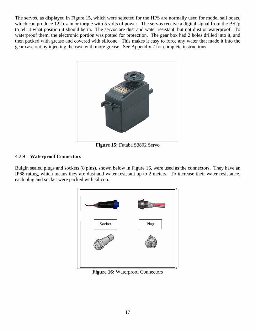
The servos, as displayed in Figure 15, which were selected for the HPS are normally used for model sail boats, which can produce 122 oz-in or torque with 5 volts of power. The servos receive a digital signal from the BS2p to tell it what position it should be in. The servos are dust and water resistant, but not dust or waterproof. To waterproof them, the electronic portion was potted for protection. The gear box had 2 holes drilled into it, and then packed with grease and covered with silicone. This makes it easy to force any water that made it into the gear case out by injecting the case with more grease. See Appendix 2 for complete instructions.
Figure 15: Futaba S3802 Servo
4.2.9 Waterproof Connectors Bulgin sealed plugs and sockets (8 pins), shown below in Figure 16, were used as the connectors. They have an IP68 rating, which means they are dust and water resistant up to 2 meters. To increase their water resistance, each plug and socket were packed with silicon.
Figure 16: Waterproof Connectors
Socket Plug
18
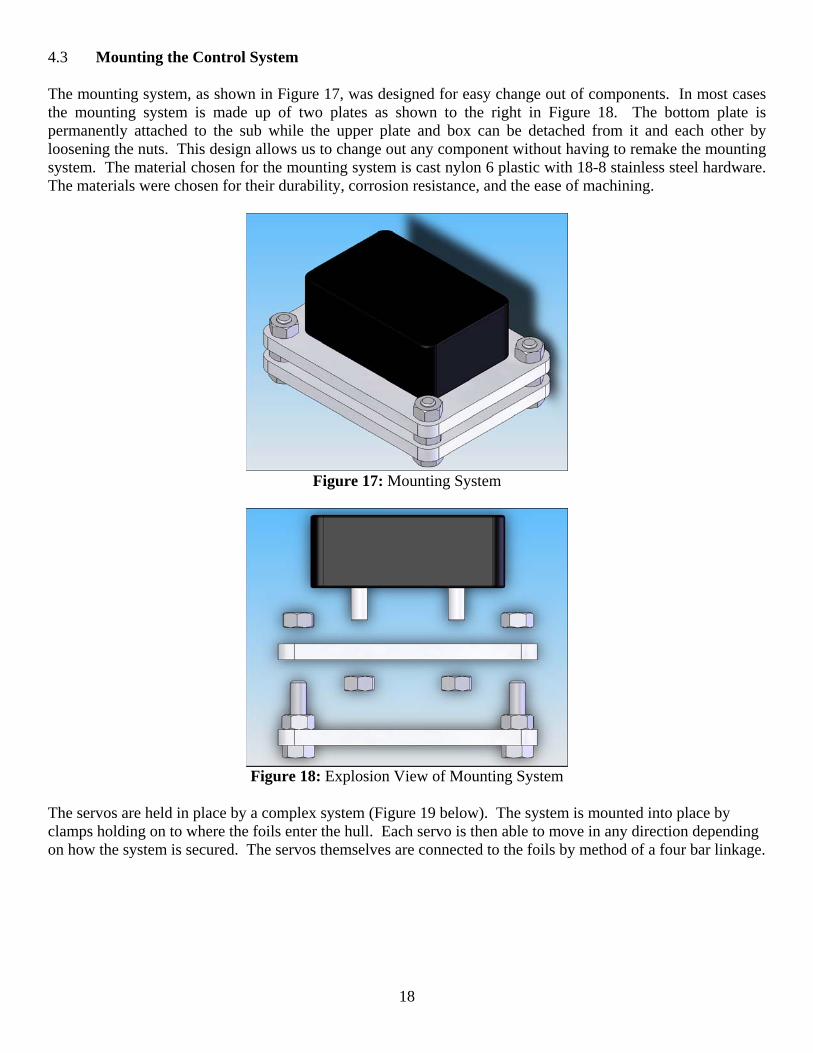
4.3 Mounting the Control System The mounting system, as shown in Figure 17, was designed for easy change out of components. In most cases the mounting system is made up of two plates as shown to the right in Figure 18. The bottom plate is permanently attached to the sub while the upper plate and box can be detached from it and each other by loosening the nuts. This design allows us to change out any component without having to remake the mounting system. The material chosen for the mounting system is cast nylon 6 plastic with 18-8 stainless steel hardware. The materials were chosen for their durability, corrosion resistance, and the ease of machining.
Figure 17: Mounting System
Figure 18: Explosion View of Mounting System
The servos are held in place by a complex system (Figure 19 below). The system is mounted into place by clamps holding on to where the foils enter the hull. Each servo is then able to move in any direction depending on how the system is secured. The servos themselves are connected to the foils by method of a four bar linkage.

19
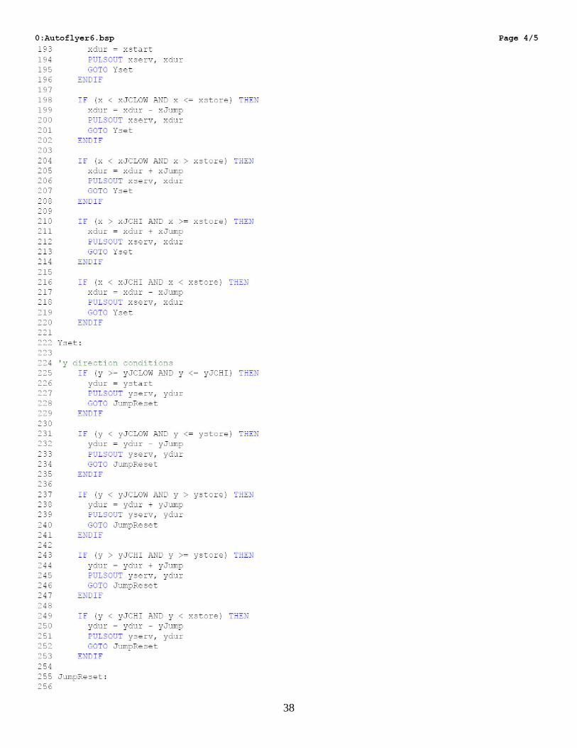
Figure 19: Servo Mounting System 4.4 Programming The language used to program the Basic Stamp is called PBasic. A copy of the program and several other useful programs can be found in the Appendix 4. The accelerometer is designed to work with the BS2p24 microprocessor. However, the Basic Stamp is not designed to measure variable resistance, which is the case with the joystick. To account for this, capacitors were used in a resistor-capacitor (RC). The RC circuit detects resistance when the capacitor is first charged with a short pulse from the basic stamp. Secondly, the voltage level vs. unit time is measured when the capacitors discharge. A scale could then be created relative to the resistance. Once the inputs from the accelerometer and joystick were established the program could be written. The basic structure of the program is a series of if then statements.
20
5. Safety 5.1 ASME Human Powered Submarine Safety Overview Life support systems: All submarines must have on board for each occupant a totally independent primary air supply. Submarines shall not operate with less than 1000-psi air pressure in any primary life support bottle. These air supplies may only be used only for life support. All air pressure tanks must have a current visual inspection and hydrostatic test, a current United States Department of Transportation (DOT) approval, and must be filled within the limits of the DOT approval. The primary air supplies shall be carried on board the submarine and have the capacity to provide adequate air supply for each crew member to propel the submarine through the course at depths to 5 meters. Breathing air pressure gages shall be readily accessible and continuously visible to the occupant breathing from the air system. Occupants, when requested, shall show pressure gages to support or safety divers. All breathing air used by the contestants shall be compressed normal atmospheric air. Special air mixtures such as Nitrox or oxygen-enriched air are prohibited. All breathing air must be delivered via an open circuit SCUBA regulator. The use of other air systems, such as re-breathers or closed-circuit systems is prohibited. Support dive air supply: All support divers shall be equipped with octopus regulators so as to support all submarine crew activities. All support divers are required to monitor their own air supply, and shall not allow their air supply to fall below 500 psi. The organizers reserve the right to inspect and declare the fitness for use of all life support equipment used by the submarine crew and team support divers. Safety requirements: Submarines shall be constructed and marked such that rescue of injured or unconscious occupants by safety divers totally unfamiliar with the submarine is simple and quick. Unassisted escape of occupants must also be simple and quick. Fluorescent orange or pink coloring is required for all devices the rescuer or occupant will need to operate for egress, including hatch releases, restraints, etc. The use of pink or orange or red markings on submarines is restricted to the specific safety requirements of these regulations and to other safety devices designated by the teams. All head and face areas of all occupants must be visible to one safety diver at one location at all times to ensure the safety of the crew. Viewports, windows, canopies, etc. are required and shall be located on the submarine such that the crew has as unrestricted view as possible, especially forward, in the case of the pilot, and such that the safety diver has the view required above. If in use, crew restraint devices must be easily visible, easily accessible and easily releasable by safety divers and the restrained occupants. Personal restraint devices must incorporate a single point release mechanism. All restraint devices, including foot restraints, must be marked with fluorescent orange or pink paint or tape. If attached to the hull, the location of restraint attach points on the hull shall be brightly marked with minimum 200 square centimeters of fluorescent orange or pink paint per hull attach point. A Hull Attach Point is the point(s) at which the harness attaches to the hull of the submarine. The mark shall be a square centered over the point or an arrow pointing to the point. The use of simple instructions such as “PULL” or “TURN” in black
21
letters approximately 3 cm high with 5 mm line width over the pink or orange field is allowed. Handles and cords incorporated in the restraint shall also be marked in pink or orange. Cords restraining occupants shall be cuttable with a standard dive knife. Towed surface floats, flashing beacons, transponders, deadman emergency buoy systems, and any other systems not specifically required by the regulations are NOT required. However, safety features which exceed the requirements of these rules are encouraged and will be considered in the election of the safety prize winner. Releasable masses or any other devices which could cause rapid ascents are prohibited. The crew compartment(s) of the submarine must be readily accessible with a hatch or canopy release mechanism. Each submarine occupant shall be able to exit the submarine without moving equipment (other than the canopy or hatch) or other occupants. Each occupant shall be able to open their applicable hatch. The handle or release mechanism(s) shall be operable from by either the occupant or external rescuer(s). The location of inside and outside release mechanisms on the hull shall be brightly marked with minimum 200 square centimeters of fluorescent orange or pink paint per release. The mark shall be a square centered over the release or an arrow pointing to the release. The use of simple instructions such as “PULL” or “TURN” in black letters approximately 3 cm high with 5 mm line width over the pink or orange field is allowed. Release handles and cords shall also be marked in pink or orange. Propeller tips, control surface tips, and other protruding devices which may entangle in nets or hit nearby divers shall be painted or marked in fluorescent orange or pink for the outermost 8-12 centimeters for easy diver recognition. Communications: Any devices which cause interference with race equipment or operations are prohibited. Diver certification: All divers, including submarine occupants and team support divers, must show current minimum “Open Water” level scuba certification by a nationally recognized diver certification organization (NAUI, PADI, YMCA, SSI, etc.). A copy of that certification must be included with the individual’s entry form. Failure to show adequate proof of certification will disqualify that individual from the HPS2006. Safety precautions: Each team is responsible for the operating worthiness of their submarine. Passing judging or implementing changes suggested by judges does not relieve the team of any liability. All submarines, life support systems, including support diver equipment must be maintained in a safe and functional condition and be operated safely at all times. A team may be disqualified and withdrawn from the HPS2006 at any time if it is judged to be operating in an unsafe manner, which includes but is not limited to: sudden surface breaching, lack of safe directional control of the sub, crewmembers who are not in a safe medical condition to be a crewmember at any time during the HPS2006, and lack of adequate communications and/or coordination with the sub’s support divers. The dive master has final authority over boats and divers in the water. Teams who endanger other submarines and divers will be advised. Recurring dangerous activity will result in the team disqualification and removal from the basin. Safety is a prime concern in this HPS2006. Any safety decisions by any safety diver or the HPS2006 chairman or his designee shall be heeded under penalty of disqualification and removal from the facility. The dive master has final authority in review of all HPS2006 safety decisions The University of Maine has set forth its own set of safety rules, primarily related to diving activities. These rules are based on the ISR rules, with a few additional qualifications required of the dive team. Please see Appendix 5 for a detailed description of diving rules for the Human Powered Submarine Team.
22
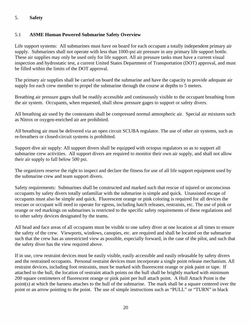
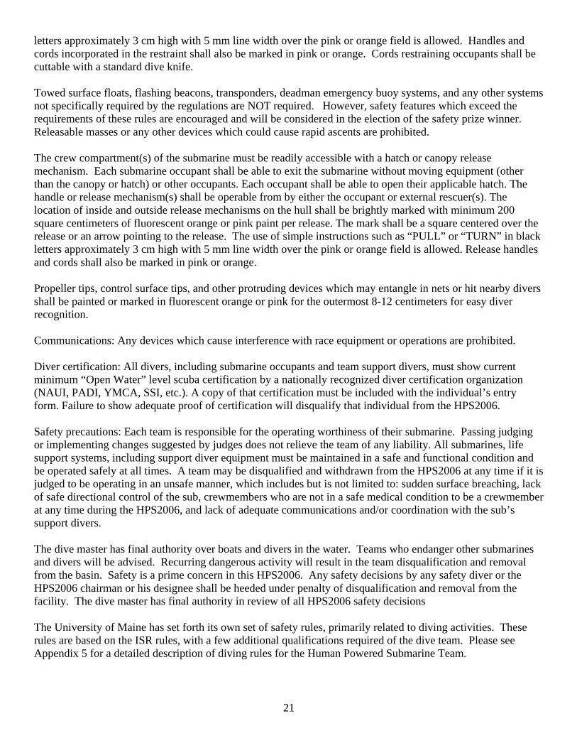
This section will deal with the safety precautions and equipment that must be built into the submarine. 5.2 Changes to Initial Design Since the hull was constructed four years ago, some rule changes have come into effect that dictate a few changes to the hull design. Other changes have been made based on situations the dive team has envisioned as worst-case scenarios. 5.2.1 Windows in the Bow In accordance with ASME Human Powered Submarine rules on crew visibility, the operator of the submarine must have unrestricted visibility, especially in the forward direction. Therefore it is necessary to fabricate and install a forward window into the existing hull of the submarine. The window is to be formed using PETG plastic, which is similar to polycarbonate except it is cheaper and forms at a much lower temperature.
The new window configuration. 5.2.2 Hatch Release Mechanism In compliance with the ASME Human Powered Submarine regulations, any escape procedure of a passenger from the submarine should be easily accessible to the passenger and any support divers on the outside. The exit at the location of the handle should be clearly marked by an orange. In combination with the regulations of ASME Human Powered Submarine and the primary design requirements, the hatch release mechanism is constructed to provide safety and consistent performance in the water. 5.2.2a Restrictions in Hatch Release Construction The initial concerns of the design team in terms of the hatch release mechanism were space requirements, emergency procedures, and accessibility. The human powered submarine itself is a confined space for any average person to be functional in. There is a small distance between the passengers back and the bottom of the hatch, so the components for the hatch take into consideration the passenger’s position.
23
If an emergency occurs underwater, the design team considered that the passenger maneuvering the submarine must be able to release the hatch from inside at any time. Along with the design and ASME Human Powered Submarine regulations, the hatch release mechanism is also constructed so that the passenger can easily push his or her back up against it, therefore releasing the hatch. In the final design, there will be the following three procedures for releasing the hatch;
1. Support diver or swimmer from the outside utilizing hand-slots to release the hatch. 2. The passenger using force to push his or her back up against the hatch, therefore easily releasing it. 3. The dead man switch for the buoy will be utilized if for some reason the passenger cannot push the
hatch open. In their Left hand will be a device similar to a bicycle brake, only when this device is squeezed, the buoy will be released.
The accessibility is another important factor in which the design team constructed the hatch release so that it is as easy to use as possible. At 20 to 30 feet below water, the hatch release needs to be simple and easy to handle. It is designed for easy use by any diver or passenger, and for convenient upkeep. 5.2.2b Modification of Initial Hatch Release Design The initial hatch release consisted of a hinge toward the aft part of the hatch and a small spring and aluminum box latch mechanism toward the fore portion. The mechanism was released by pulling a thin piece of string. In accordance to the previous regulations, this design needed to be modified. This year’s team thought it would be best to create a hatch that wasn’t restricted by any complex latch or cable system. Instead, the team decided to use strong magnets to hold the hatch down. They are strong enough to withstand a slight bump from the driver of the sub but are still weak enough to be pushed through by the driver, or pulled off by support divers. 5.2.3 Safety Buoy In the event of an emergency, it is required that the sub be equipped with a highly visible pop-up safety buoy that can alert the safety crew of any problems. While in operation, the driver grips a “dead-man switch” that holds the buoy tightly to the hull of the vessel. If the operator of the submarine gets stuck or needs help at any point, the buoy can be released to the surface by squeezing a switch. 6. Diving Guidelines 6.1 University of Maine Sub Diving Guidelines See Appendix 5 6.4.1 Preparing the Sub for Water Entry A pvc rack was designed and built for easy transportation and storage of the sub. This rack can be lowered down into the tank with the sub on it to allow easy access for the support divers and main diver to the sub. Small holes were drilled in the pvc to allow any air in the pipes to escape while the rack is being lowered into the tank. This rack allows the team to position the sub before bringing the diver down for the run. All tanks in the sub are checked for required pressure levels. The extended octopus line from the sub is coiled up in a manner that is easy to access and provide for the sub operator.
24
6.4.2 Operator Entry The operator is provided air from the extended octopus line of the main support diver during descent to the sub. The main support diver assists the operator in grabbing hold of the entry hole of the sub. The operator places feet in the pedals at the rear of the sub, then aligns their upper body in the front of the sub. The operator then switches from the main support diver's air supply to the main sub supply line. They will then check the gages from the sub air supply, and then display the gage reading to the safety divers through the windows in the front of the sub. 6.4.3.1 Operator Exit Standard Procedures The operator exits the sub by pressing their upper back into the exit hatch. The magnetic design of the hatch allows for easy release. The hatch is also slightly positively buoyant for the safety of the diver. The operator then takes feet out of the pedals, and lifts their upper body out of the front of the sub through the now open hatch. The operator is assisted out of the hatch by the support divers and given one of their regulators to switch air supplies. The support divers then assist the operator safely to the surface. 6.4.3.2 Operator Exit Emergency Procedures In case of operator emergency, the safety divers will enter the sub by first removing the hatch of the sub. The safety diver will then place one arm around the torso of the operator, then the other hand supporting the head of the operator while supporting the air supply in the operator's mouth. The safety diver will then replace the air supply from the sub with their own octopus in the operator's mouth. The safety diver will then carefully remove the operator from the sub without contacting them with the sub edges or parts. While keeping arms in the rescue position on the operator, the safety diver positions themselves under the operator and swims at an angle to the surface of the water. Once at the surface, the diver calls for help, keeps the body of the operator supported and face above water. All other support divers will be there to assist in any of these tasks, while trying to keep the operator's body in safe positions at all times. The task of rescuing an unconscious diver from the sub is meant to be possible by using a minimum of one safety diver. This increases the chances of safety and survival for the operator. The dive team must first be certified Research Divers by the Dive Safety Officer (DSO). At that point, the team will begin to formulate the operational dive plan for the submarine.
25
Appendix 1: Mathematical Model
Fdragz cDbodyz θ( ) 12
⋅ ρ⋅ Sbodyz⋅ddt
z⋅⎛⎜⎝
⎞⎠
2⋅:=
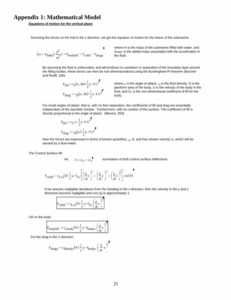
For the drag in the Z direction:
Fbodylift cLbody θ( ) 12
⋅ ρ⋅ Sbodyz⋅txd
d⎛⎜⎝
⎞⎠
2⋅:=
Lift on the body:
Fcslift cLcs δ( ) 12
⋅ ρ⋅ Scs⋅txd
d⎛⎜⎝
⎞⎠
2⋅:=
If we assume negligible deviations from the heading in the x direction, then the velocity in the y and z directions become negligible and cos (θ) is approximately 1.
Fcslift cLcs δ( ) 12
⋅ ρ⋅ Scs⋅txd
d⎛⎜⎝
⎞⎠
2
tyd
d⎛⎜⎝
⎞⎠
2+
tzd
d⎛⎜⎝
⎞⎠
2+
⎡⎢⎣
⎤⎥⎦
⋅ cos θ( )⋅:=
summation of both control surface deflectionsδ α1 α2+:=let:
The Control Surface lift:
Now the forces are expressed in terms of known quantities; ρ, S, and free stream velocity U, which will be sensed by a flow-meter.
Fdrag cD α( ) 12
⋅ ρ S⋅ U2⋅:=
Flift cL α⋅12
⋅ ρ S⋅ U2⋅:=
For small angles of attack, that is, with no flow seperation, the coefficients of lift and drag are essentially independant of the reynolds number. Furthermore, with no camber of the surface, The coefficient of lift is directly proportional to the angle of attack. (Blevins, 353).
Fdrag cD α Re,( ) 12
⋅ ρ S⋅ U2⋅:=
where α is the angle of attack, ρ is the fluid density, S is the planform area of the body, U is the velocity of the body in the fluid, and CL is the non-dimensional coefficient of lift for the body.
Flift cL α Re,( ) 12
⋅ ρ S⋅ U2⋅:=
By assuming the fluid is unbounded, and will produce no cavitation or seperation of the boundary layer around the lifting bodies, these forces can then be non-dimensionalized using the Buckingham-Pi theorem (Burcher and Rydill, 160).
m maddz+( ) 2tzd
d
2⋅ Fbodylift Fcslift+ Fdragz−:=
where m is the mass of the submarine filled with water, and maddz is the added mass associated with the acceleration in the fluid.
Summing the forces on the hull in the z direction, we get the equation of motion for the heave of the submarine.
Equations of motion for the vertical plane
26
b5 cDθ12
⋅ ρ⋅ Sbodyz⋅ reff⋅:=
b4 m g⋅ dcb.cg⋅:=a4 cDbodyz12
⋅ ρ⋅ Sbodyz⋅:=
b3 cLcs12
⋅ ρ⋅ Scs⋅ dcs.cg⋅:=a3 cLcs12
⋅ ρ⋅ Scs⋅:=
b2 cLbody12
⋅ ρ⋅ Sbodyz⋅ dcl.cg⋅:=a2 cLbody12
⋅ ρ⋅ Sbodyz⋅:=
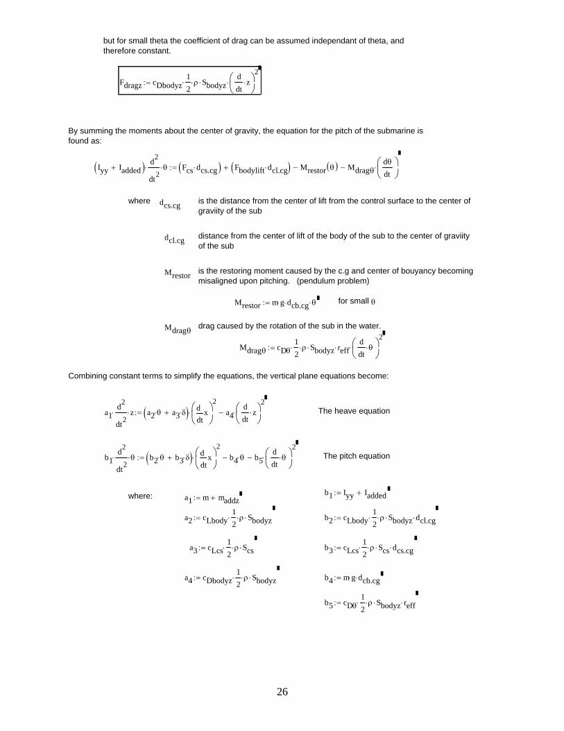
a1 m maddz+:=where: b1 Iyy Iadded+:=
The pitch equationb1d2
dt2⋅ θ⋅ b2 θ⋅ b3 δ⋅+( )
txd
d⎛⎜⎝
⎞⎠
2⋅ b4 θ⋅− b5
ddt
θ⋅⎛⎜⎝
⎞⎠
2⋅−:=
The heave equationa1d2
dt2⋅ z⋅ a2 θ⋅ a3 δ⋅+( )
txd
d⎛⎜⎝
⎞⎠
2⋅ a4
ddt
z⋅⎛⎜⎝
⎞⎠
2⋅−:=
Combining constant terms to simplify the equations, the vertical plane equations become:
Mdragθ cDθ12
⋅ ρ⋅ Sbodyz⋅ reff⋅ddt
θ⋅⎛⎜⎝
⎞⎠
2⋅:=
drag caused by the rotation of the sub in the water.Mdragθ
for small θMrestor m g⋅ dcb.cg⋅ θ⋅:=
is the restoring moment caused by the c.g and center of bouyancy becoming misaligned upon pitching. (pendulum problem)
Mrestor
distance from the center of lift of the body of the sub to the center of graviity of the sub
dcl.cg
is the distance from the center of lift from the control surface to the center of graviity of the sub
dcs.cgwhere
Iyy Iadded+( ) d2
dt2⋅ θ⋅ Fcs dcs.cg⋅( ) Fbodylift dcl.cg⋅( )+ Mrestor θ( )− Mdragθ
dθ
dt⎛⎜⎝
⎞⎠
⋅−:=
By summing the moments about the center of gravity, the equation for the pitch of the submarine is found as:
Fdragz cDbodyz12
⋅ ρ⋅ Sbodyz⋅ddt
z⋅⎛⎜⎝
⎞⎠
2⋅:=
but for small theta the coefficient of drag can be assumed independant of theta, and therefore constant.
27
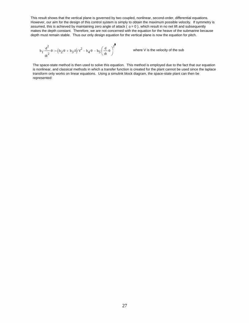
This result shows that the vertical plane is governed by two coupled, nonlinear, second-order, differential equations. However, our aim for the design of this control system is simply to obtain the maximum possible velocity. If symmetry is assumed, this is achieved by maintaining zero angle of attack ( θ = 0 ), which result in no net lift and subsequently makes the depth constant. Therefore, we are not concerned with the equation for the heave of the submarine because depth must remain stable. Thus our only design equation for the vertical plane is now the equation for pitch.
b1d2
dt2⋅ θ⋅ b2 θ⋅ b3 δ⋅+( ) V2
⋅ b4 θ⋅− b5ddt
θ⋅⎛⎜⎝
⎞⎠
2⋅−:= where V is the velocity of the sub
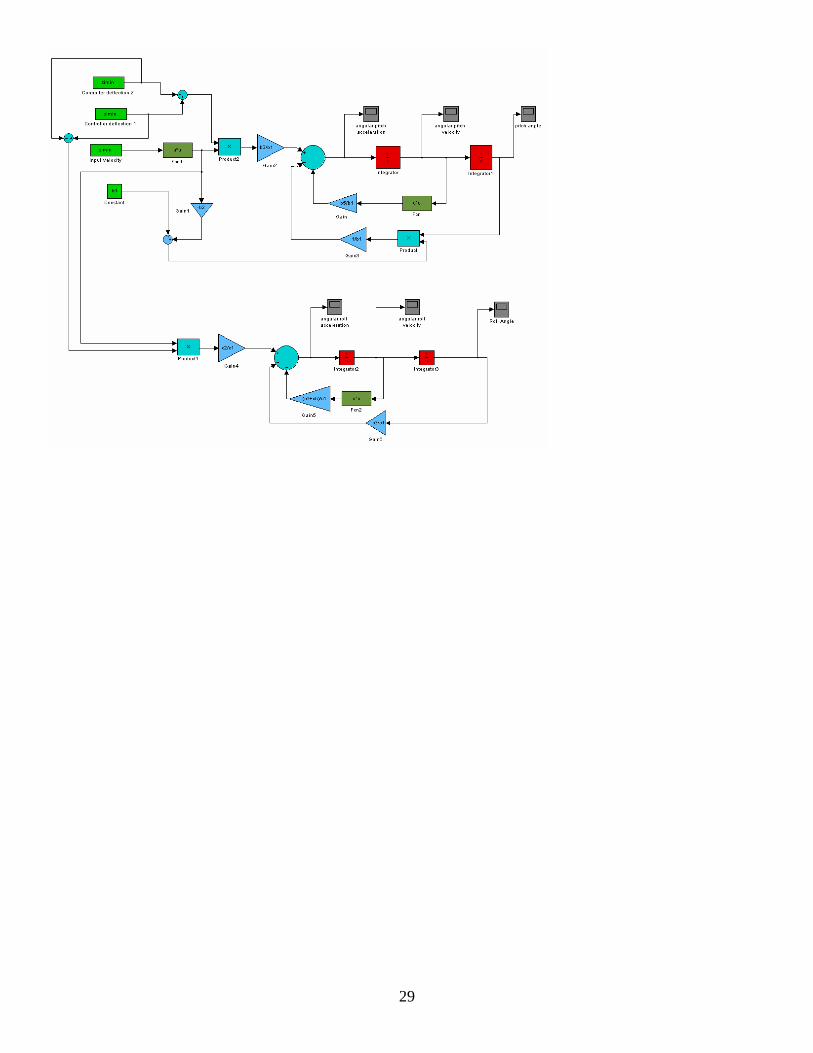
The space-state method is then used to solve this equation. This method is employed due to the fact that our equation is nonlinear, and classical methods in which a transfer function is created for the plant cannot be used since the laplace transform only works on linear equations. Using a simulink block diagram, the space-state plant can then be represented:
28
Viscous Drag:
Mviscφ cDφ12
⋅ ρ⋅ SA⋅ reffφ⋅ddt
φ⋅⎛⎜⎝
⎞⎠
2⋅:=
Rudder Drag: Assuming small deflections, and combining all four surfaces.
Mrudder cDcsφ 2⋅ ρ⋅ Scs⋅ dcs.cg⋅ddt
φ⋅⎛⎜⎝
⎞⎠
2⋅:=
Restoring Moment:
Mrestor m g⋅ dcb.cg⋅ φ⋅:= for small φ, sin(φ)=φ (approximately)
To simplify the equation, constant terms are combined
c1d2
φ⋅
dt2⋅ c2 ζ⋅ V2
⋅⎛⎝
⎞⎠ c3 φ⋅− c4 c5+( ) d
dtφ⋅⎛⎜
⎝⎞⎠
2⋅−:=
where: c1 Ixx:=
c2 cLcs12
⋅ ρ⋅ Scs⋅ dcs.cg⋅:=
c3 m g⋅ dcb.cg⋅:=
c4 cDφ12
⋅ ρ⋅ SA⋅ reffφ⋅:=
c5 cDcsφ 2⋅ ρ⋅ Scs⋅ dcs.cg⋅:=
As Before, this equation is also non-linear, second-order, nonhomogeneous, and with variable coefficients. Therefore the state-space method will again be used to create a simulink model of the plant.
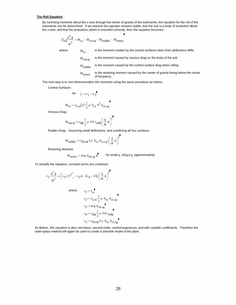
The Roll Equation :
By summing moments about the x-axis through the center of gravity of the submarine, the equation for the roll of the submarine can be determined. If we assume the operator remains stable, that the sub is a body of revolution about the x-axis, and that the propulsion sytem is mounted correctly, then the equation becomes:
Ixx( ) d2φ⋅
dt2Mcs Mviscφ− Mrudder− Mrestor−:=
where: Mcs is the moment created by the control surfaces when their deflections differ
Mviscφ is the moment caused by viscous drag on the body of the sub
Mrudder is the moment caused by the control surface drag when rolling
Mrestor is the restoring moment caused by the center of gravity being below the center of bouyancy.
The next step is to non-dimensionalize the moments using the same procedure as before.
Control Surfaces
let ζ α1 α2−:=
Mcs cLcs ζ( ) 12
⋅ ρ⋅ Scs⋅ V2⋅ dcs.cg⋅:=
29
30
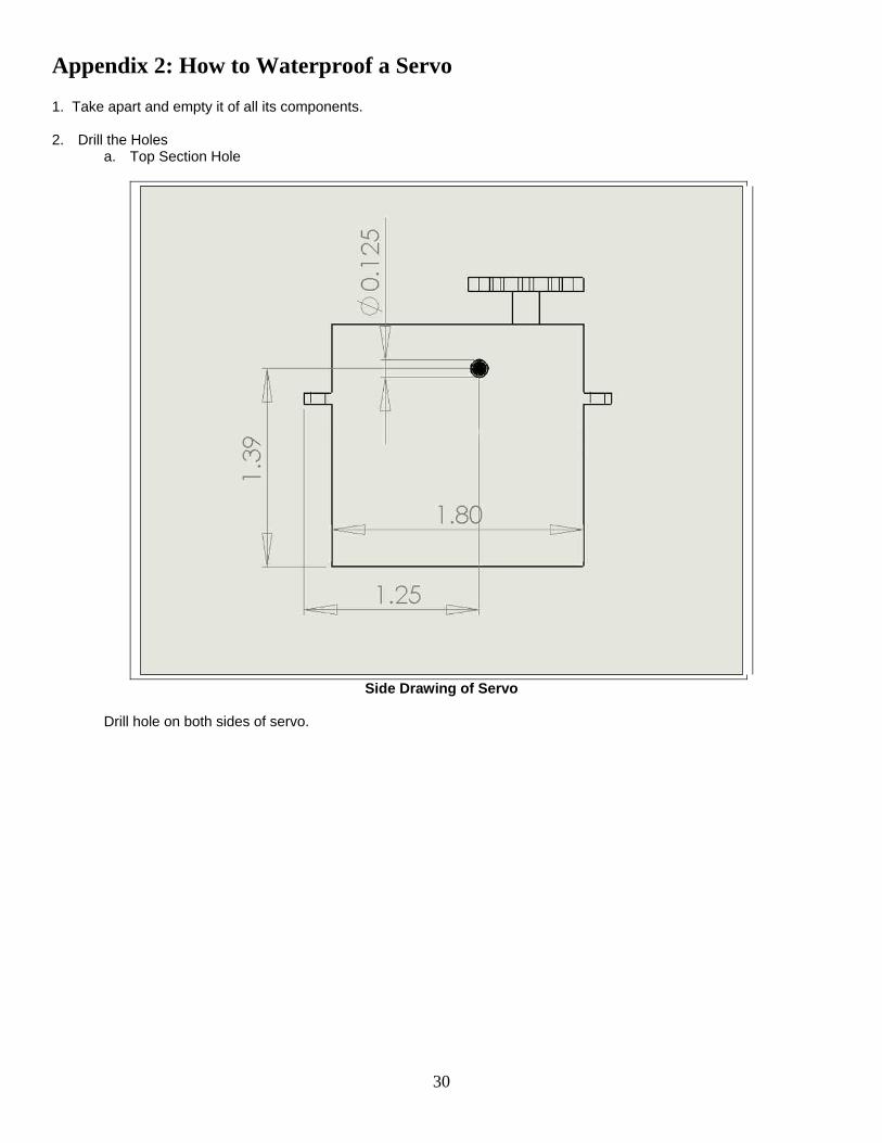
Appendix 2: How to Waterproof a Servo 1. Take apart and empty it of all its components. 2. Drill the Holes
a. Top Section Hole
Side Drawing of Servo
Drill hole on both sides of servo.
31
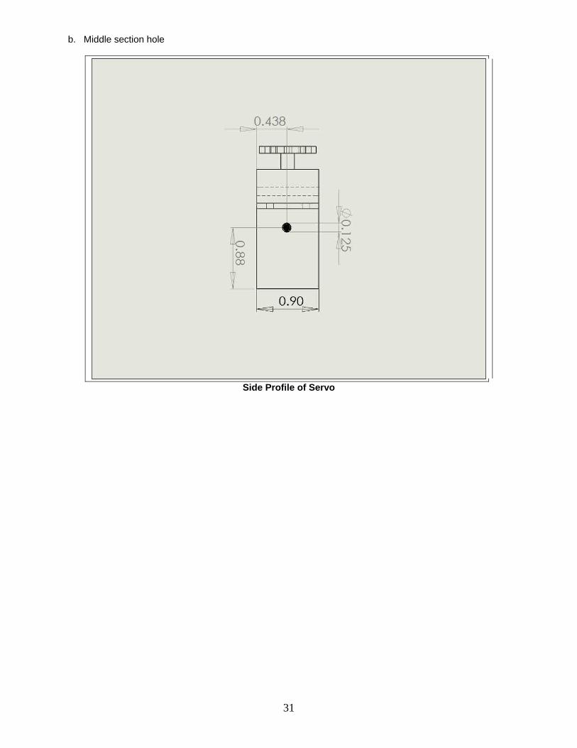
b. Middle section hole
Side Profile of Servo
32
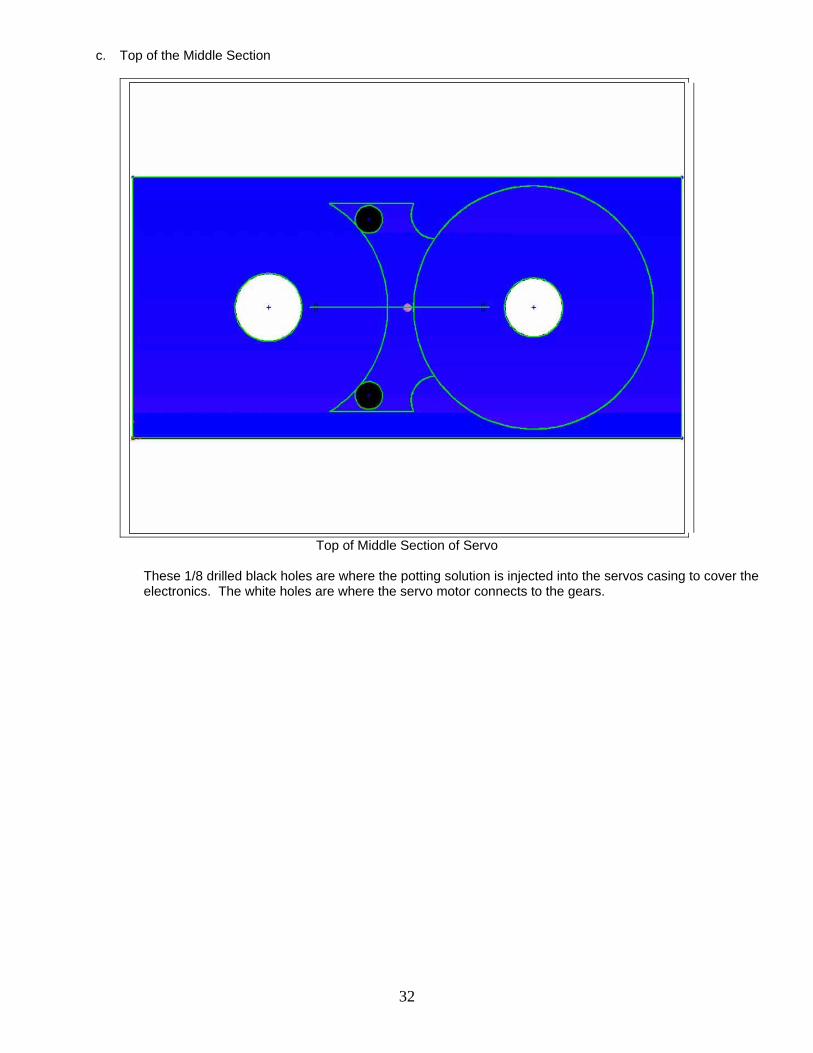
c. Top of the Middle Section
Top of Middle Section of Servo
These 1/8 drilled black holes are where the potting solution is injected into the servos casing to cover the electronics. The white holes are where the servo motor connects to the gears.
33
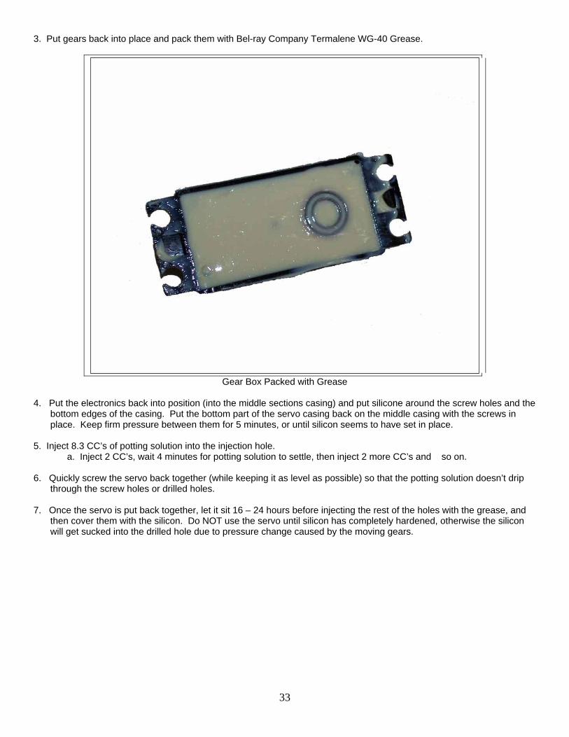
3. Put gears back into place and pack them with Bel-ray Company Termalene WG-40 Grease.
Gear Box Packed with Grease
4. Put the electronics back into position (into the middle sections casing) and put silicone around the screw holes and the
bottom edges of the casing. Put the bottom part of the servo casing back on the middle casing with the screws in place. Keep firm pressure between them for 5 minutes, or until silicon seems to have set in place.
5. Inject 8.3 CC’s of potting solution into the injection hole.
a. Inject 2 CC’s, wait 4 minutes for potting solution to settle, then inject 2 more CC’s and so on.
6. Quickly screw the servo back together (while keeping it as level as possible) so that the potting solution doesn’t drip through the screw holes or drilled holes.
7. Once the servo is put back together, let it sit 16 – 24 hours before injecting the rest of the holes with the grease, and
then cover them with the silicon. Do NOT use the servo until silicon has completely hardened, otherwise the silicon will get sucked into the drilled hole due to pressure change caused by the moving gears.
34
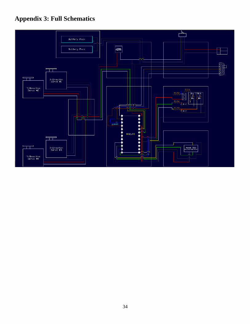
Appendix 3: Full Schematics
35
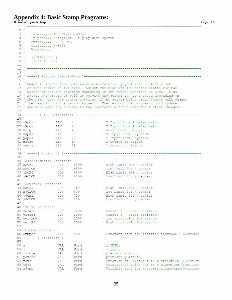
Appendix 4: Basic Stamp Programs:

36

37
38

39
40
Appendix 5: UMaine Diving Safety Regulations
GUIDELINES FOR MANNED WET SUBMERSIBLE DIVING
(International Submarine Races or similar)
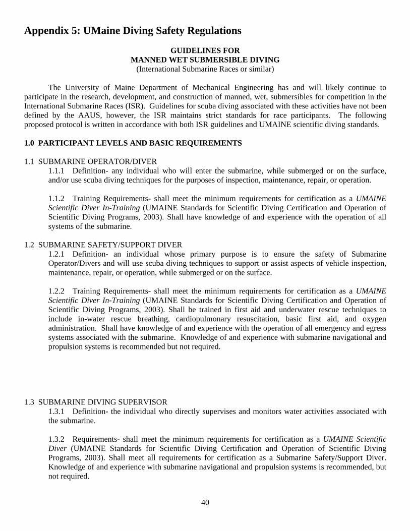
The University of Maine Department of Mechanical Engineering has and will likely continue to participate in the research, development, and construction of manned, wet, submersibles for competition in the International Submarine Races (ISR). Guidelines for scuba diving associated with these activities have not been defined by the AAUS, however, the ISR maintains strict standards for race participants. The following proposed protocol is written in accordance with both ISR guidelines and UMAINE scientific diving standards. 1.0 PARTICIPANT LEVELS AND BASIC REQUIREMENTS 1.1 SUBMARINE OPERATOR/DIVER
1.1.1 Definition- any individual who will enter the submarine, while submerged or on the surface, and/or use scuba diving techniques for the purposes of inspection, maintenance, repair, or operation. 1.1.2 Training Requirements- shall meet the minimum requirements for certification as a UMAINE Scientific Diver In-Training (UMAINE Standards for Scientific Diving Certification and Operation of Scientific Diving Programs, 2003). Shall have knowledge of and experience with the operation of all systems of the submarine.
1.2 SUBMARINE SAFETY/SUPPORT DIVER
1.2.1 Definition- an individual whose primary purpose is to ensure the safety of Submarine Operator/Divers and will use scuba diving techniques to support or assist aspects of vehicle inspection, maintenance, repair, or operation, while submerged or on the surface. 1.2.2 Training Requirements- shall meet the minimum requirements for certification as a UMAINE Scientific Diver In-Training (UMAINE Standards for Scientific Diving Certification and Operation of Scientific Diving Programs, 2003). Shall be trained in first aid and underwater rescue techniques to include in-water rescue breathing, cardiopulmonary resuscitation, basic first aid, and oxygen administration. Shall have knowledge of and experience with the operation of all emergency and egress systems associated with the submarine. Knowledge of and experience with submarine navigational and propulsion systems is recommended but not required.
1.3 SUBMARINE DIVING SUPERVISOR
1.3.1 Definition- the individual who directly supervises and monitors water activities associated with the submarine. 1.3.2 Requirements- shall meet the minimum requirements for certification as a UMAINE Scientific Diver (UMAINE Standards for Scientific Diving Certification and Operation of Scientific Diving Programs, 2003). Shall meet all requirements for certification as a Submarine Safety/Support Diver. Knowledge of and experience with submarine navigational and propulsion systems is recommended, but not required.
41
1.4 SUBMARINE SUPPORT SWIMMER
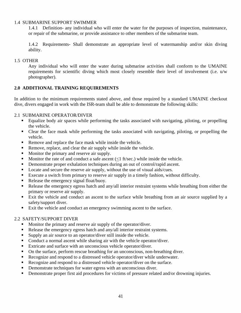
1.4.1 Definition- any individual who will enter the water for the purposes of inspection, maintenance, or repair of the submarine, or provide assistance to other members of the submarine team. 1.4.2 Requirements- Shall demonstrate an appropriate level of watermanship and/or skin diving ability.
1.5 OTHER
Any individual who will enter the water during submarine activities shall conform to the UMAINE requirements for scientific diving which most closely resemble their level of involvement (i.e. u/w photographer).
2.0 ADDITIONAL TRAINING REQUIREMENTS In addition to the minimum requirements stated above, and those required by a standard UMAINE checkout dive, divers engaged in work with the ISR-team shall be able to demonstrate the following skills: 2.1 SUBMARINE OPERATOR/DIVER
Equalize body air spaces while performing the tasks associated with navigating, piloting, or propelling the vehicle.
Clear the face mask while performing the tasks associated with navigating, piloting, or propelling the vehicle.
Remove and replace the face mask while inside the vehicle. Remove, replace, and clear the air supply while inside the vehicle. Monitor the primary and reserve air supply. Monitor the rate of and conduct a safe ascent (<1 ft/sec.) while inside the vehicle. Demonstrate proper exhalation techniques during an out of control/rapid ascent. Locate and secure the reserve air supply, without the use of visual aids/cues. Execute a switch from primary to reserve air supply in a timely fashion, without difficulty. Release the emergency signal float/buoy. Release the emergency egress hatch and any/all interior restraint systems while breathing from either the
primary or reserve air supply. Exit the vehicle and conduct an ascent to the surface while breathing from an air source supplied by a
safety/support diver. Exit the vehicle and conduct an emergency swimming ascent to the surface.
2.2 SAFETY/SUPPORT DIVER
Monitor the primary and reserve air supply of the operator/diver. Release the emergency egress hatch and any/all interior restraint systems. Supply an air source to an operator/diver still inside the vehicle. Conduct a normal ascent while sharing air with the vehicle operator/diver. Extricate and surface with an unconscious vehicle operator/diver. On the surface, perform rescue breathing for an unconscious, non-breathing diver. Recognize and respond to a distressed vehicle operator/diver while underwater. Recognize and respond to a distressed vehicle operator/diver on the surface. Demonstrate techniques for water egress with an unconscious diver. Demonstrate proper first aid procedures for victims of pressure related and/or drowning injuries.
42
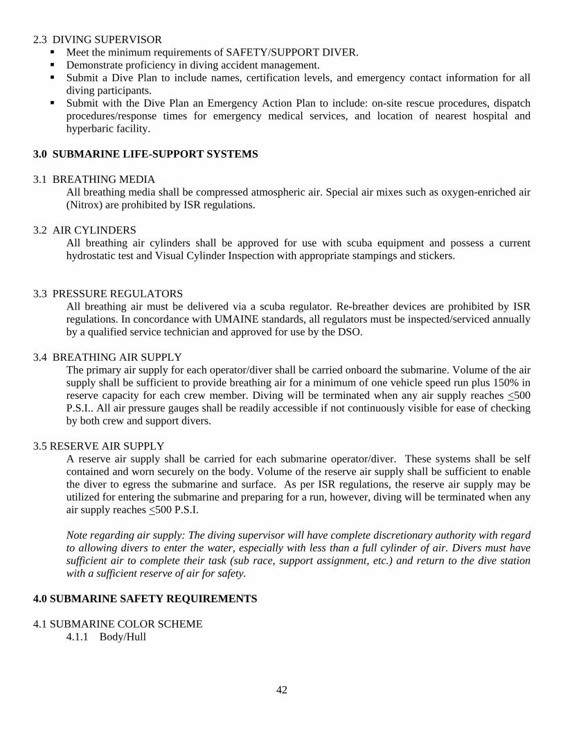
2.3 DIVING SUPERVISOR Meet the minimum requirements of SAFETY/SUPPORT DIVER. Demonstrate proficiency in diving accident management. Submit a Dive Plan to include names, certification levels, and emergency contact information for all
diving participants. Submit with the Dive Plan an Emergency Action Plan to include: on-site rescue procedures, dispatch
procedures/response times for emergency medical services, and location of nearest hospital and hyperbaric facility.
3.0 SUBMARINE LIFE-SUPPORT SYSTEMS 3.1 BREATHING MEDIA
All breathing media shall be compressed atmospheric air. Special air mixes such as oxygen-enriched air (Nitrox) are prohibited by ISR regulations.
3.2 AIR CYLINDERS
All breathing air cylinders shall be approved for use with scuba equipment and possess a current hydrostatic test and Visual Cylinder Inspection with appropriate stampings and stickers.
3.3 PRESSURE REGULATORS
All breathing air must be delivered via a scuba regulator. Re-breather devices are prohibited by ISR regulations. In concordance with UMAINE standards, all regulators must be inspected/serviced annually by a qualified service technician and approved for use by the DSO.
3.4 BREATHING AIR SUPPLY
The primary air supply for each operator/diver shall be carried onboard the submarine. Volume of the air supply shall be sufficient to provide breathing air for a minimum of one vehicle speed run plus 150% in reserve capacity for each crew member. Diving will be terminated when any air supply reaches <500 P.S.I.. All air pressure gauges shall be readily accessible if not continuously visible for ease of checking by both crew and support divers.
3.5 RESERVE AIR SUPPLY
A reserve air supply shall be carried for each submarine operator/diver. These systems shall be self contained and worn securely on the body. Volume of the reserve air supply shall be sufficient to enable the diver to egress the submarine and surface. As per ISR regulations, the reserve air supply may be utilized for entering the submarine and preparing for a run, however, diving will be terminated when any air supply reaches <500 P.S.I. Note regarding air supply: The diving supervisor will have complete discretionary authority with regard to allowing divers to enter the water, especially with less than a full cylinder of air. Divers must have sufficient air to complete their task (sub race, support assignment, etc.) and return to the dive station with a sufficient reserve of air for safety.
4.0 SUBMARINE SAFETY REQUIREMENTS 4.1 SUBMARINE COLOR SCHEME
4.1.1 Body/Hull
43
ISR advises that, for the purposes of easy location, each submarine be painted with high-visibility coloration using light colors (i.e. white, yellow, orange, etc.). Florescent or contrasting schemes are advisable to make the submarine distinct. ISR also recommends that the contestants feature the team or submarine name prominently on the hull. The listing of sponsors, affiliates, or team members is also acceptable.
4.1.2 Propeller Propeller tips must be painted or marked in bright orange for easy recognition by safety/support divers.
4.2 EMERGENCY EGRESS
Any and all exits that are to be used by the vehicle crew for emergency egress shall be clearly marked at the location of the handle or release mechanism by a 4” square orange patch bearing the word ‘Rescue’. If this is not possible, the handle or release mechanism should be clearly marked with florescent tape at a minimum. The handle or release mechanism shall be easily accessible from both inside and outside the submarine. Safety and support divers must be familiar with the operation of the emergency egress mechanism(s).
4.3 CREW RESTRAINTS
Any method of attachment of a crew member to the submarine, such as restraining harnesses or toe-clips, must have the release system clearly marked with orange paint or florescent tape. Safety/support divers must be familiar with the release mechanisms of any/all crew restraints.
4.4 CREW VISIBILITY
View ports, windows, canopies, etc. shall be located on the submarine so that the crew has as unrestricted a view as possible, especially forward, for navigation purposes. Additionally, the crew face and head areas shall be visible to safety/support divers at all times.
4.5 STROBE LIGHT
Each submarine shall carry a flashing white strobe light that is visible for 360 degrees in the horizontal plane. The light should flash at an approximate rate of once per second, be visible for at least thirty feet under normal visibility conditions, have sufficient power to flash for one hour at a minimum, and be operating whenever the submarine is submerged. If preferred, the design may incorporate more than one strobe light, so long as the flash is visible for all 360 degrees in the horizontal plane.
4.6 EMERGENCY BUOY
All submarines shall carry a high visibility buoy that will release from the hull and float to the surface in the event of an emergency. The float must be attached to the submarine by thirty (30) feet of strong, highly visible line, at least 1/16” thick. Each crew member shall have a dead-man type switch that will automatically release the float in the event that they are disabled. Switch safety mechanisms may be employed during staging to prevent inadvertent release, but the switches MUST be activated whenever the submarine is operating. Buoy release will initiate an emergency rescue by the safety divers whose primary interest will be removing the crew member(s) from the submarine and to the surface as quickly as possible. If a buoy is released inadvertently, crew members should make every attempt to indicate visually to the safety divers using the diver’s OK signal.
5.0 SUBMARINE SAFETY INSPECTION
44
As is the case during ISR competition, the vehicle shall receive a safety inspection prior to entering the water. A second safety inspection shall be conducted in the water prior to crew entry. At minimum the safety inspection shall consist of an inspection and functional test of the following components:
Life-support systems and air supplies Emergency egress hatch and crew restraints Emergency signal buoy
6.0 SUPPORT PERSONNEL 6.1 SAFETY/SUPPORT DIVERS During vehicle deployment and operation a minimum of two (2) Safety/Support Divers shall be in the water readily available to assist the submarine crew. Additional Safety/Support Divers should be staged nearby ready to enter the water in the event of an emergency.
6.1.1 Equipment Requirements- Safety/Support Divers shall be equipped as outlined in Section 3.0 of the UMAINE Standards for Scientific Diving Certification and Operation of Scientific Diving Programs, 2003. 6.1.2 Air Supply- Support divers shall be equipped with octopus regulators so as to support submarine crew activities such during ingress/egress of the submarine at depth. Octopus regulator hoses must be of sufficient length to accommodate the sharing of air while the operator/diver is inside the vehicle. All support divers are required to monitor their own air supply and shall not allow their air supply to fall below 500 P.S.I. Note regarding air supply: The diving supervisor will have complete discretionary authority with regard to allowing divers to enter the water, especially with less than a full cylinder of air. Divers must have sufficient air to complete their task (sub race, support assignment, etc.) and return to the dive station with a sufficient reserve of air for safety.
6.2 DIVING SUPERVISOR A qualified Diving Supervisor shall be on site and readily available at all times during water activities. The Diving Supervisor is responsible for ensuring that divers maintain compliance with UMAINE diving standards including proper documentation of diving activities. The Diving Supervisor may also act as a Safety/Support diver.
6.2.1 Emergency Equipment- The Diving Supervisor will ensure that emergency first aid equipment, including emergency oxygen, is available at the dive site. 6.2.2 Documentation- The Diving Supervisor will ensure that participating divers record their activities on a standard UMAINE Dive Log for submission to the DSO.