Embed Size (px)
Citation preview
University of Maryland HASP 2012 Final Report
Stratopigeon III Connie Ciarleglio
Kristy Weber
Lauren Powers
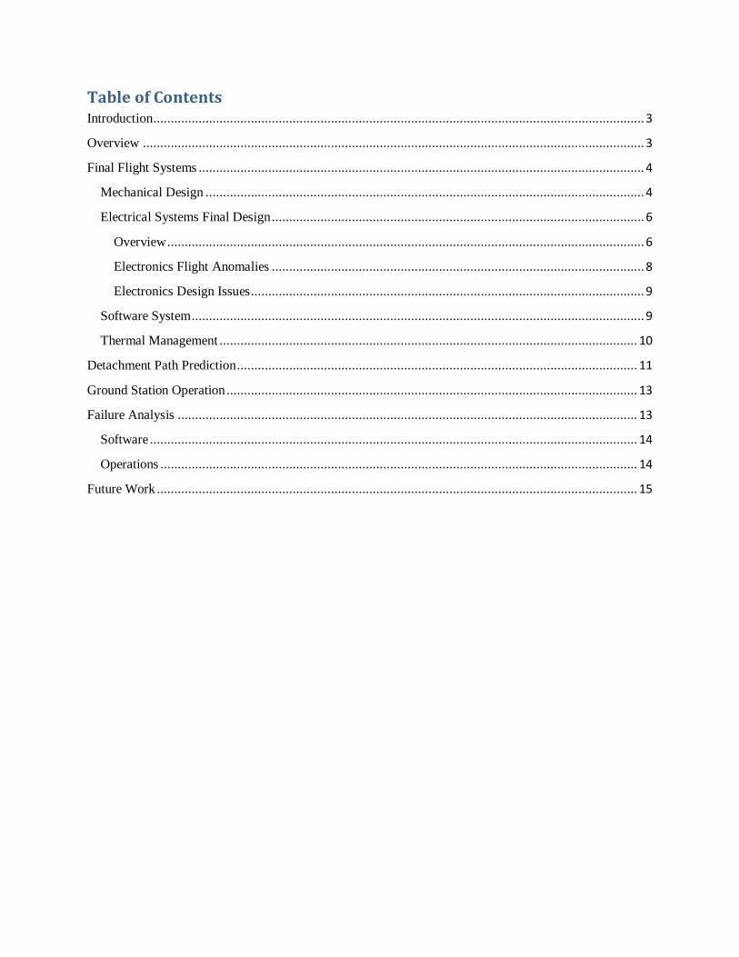
Table of Contents Introduction ............................................................................................................................................. 3
Overview ................................................................................................................................................ 3
Final Flight Systems ................................................................................................................................ 4
Mechanical Design .............................................................................................................................. 4
Electrical Systems Final Design ........................................................................................................... 6
Overview ......................................................................................................................................... 6
Electronics Flight Anomalies ........................................................................................................... 8
Electronics Design Issues ................................................................................................................. 9
Software System .................................................................................................................................. 9
Thermal Management ........................................................................................................................ 10
Detachment Path Prediction ................................................................................................................... 11
Ground Station Operation ...................................................................................................................... 13
Failure Analysis .................................................................................................................................... 13
Software ............................................................................................................................................ 14
Operations ......................................................................................................................................... 14
Future Work .......................................................................................................................................... 15
Introduction
The University of Maryland (UMD) HASP team is pleased to submit the final report for the 2012
University of Maryland payload, Stratopigeon III. The University of Maryland has participated
in 4 years of HASP flights, including 2 years of Stratopigeon payload tests. This report details
the final design and testing results of the Stratopigeon payload, a new approach to data storage
and delivery for LDB and ULDB Antarctic high altitude balloon flights. The Stratopigeon
payload has been supported and funded in testing and flight by the Maryland Space Grant
Consortium, with oversight and support from the UMD Space Systems Lab.
Overview
As the technology and techniques of high altitude ballooning improves, the duration of
LDB and ULDB Antarctic flights have lengthened. Flights in excess of 3 months are now
possible, allowing scientists more access time to the desired environment than previously
available. As payload technology has also advanced, many research payloads are collecting
more data, as much as several terabytes over a few weeks.
Research payloads store collected data on board, with a slower ground station link to
verify payload functionality and data validity. Normally, a satellite link, such as Iridium or
TDRS, or a line of sight link is used. These links are capable of data rates in the tens to hundreds
of kilobits per second, a low enough rate that the majority of scientific data remains on board the
payload for the duration of the flight. Due to the payload size, weight, and weather conditions of
the landing site, recovery of on-board data is a difficult, resource and time consuming task.
Experienced personnel and multiple plane trips are required for payload retrieval based on
landing location, delaying recovery for days, weeks, or, rarely, not at all.
Stratopigeon III is the second generation prototype of a data storage and delivery capsule
designed for supplemental data storage and mid-flight delivery of a high volume of scientific
data. The small size of the capsule and ability to release the capsule at any point during flight
allows easy retrieval of scientific data mid-flight. Not only does early retrieval allow for
correction of anomalies shown in the data during flight, but analysis of a more complete data set
can be accomplished at multiple points along the flight timeline.
The 2012 Stratopigeon capsule was designed specifically to minimize integration
difficulty with already established research payloads. The data capsule was built and tested on
the 2012 HASP flight and refines the previous prototype flown in 2010.
Final Flight Systems
Mechanical Design
The mechanical system disconnects the
payload and electrical connections from the
gondola. Deployment of the payload is actuated
by a linear stepper motor capable of outputting
twenty-four pounds of force. The motor turns a nut
inside its body and drives out a M6.35 threaded
rod, approximately one and quarter inches in
length, which is securely bolted to the top of the
payload. This actuator, made by Anaheim
Automation, is a simple and lightweight linear
drive system that provides enough force, with
safety margin, to detach the payload. Stainless
steel guide pins, mounted to the HASP interface
plate, guide the payload out on Teflon linear
bearings, to prevent torquing during deployment
and to guide the payload into place during
assembly. Due to internal configuration of the
payload, a single guide pin was used. The
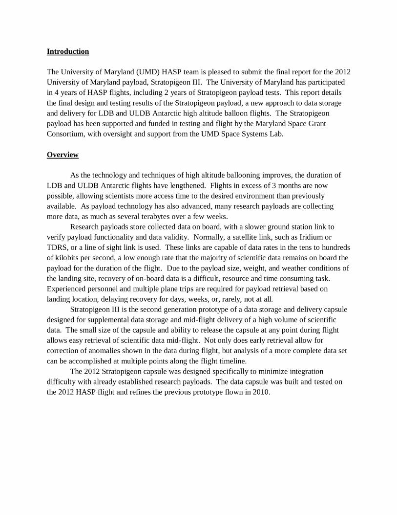
threaded rod, Teflon guides, and female
Hypertronics connectors are attached on the
payload and fall to earth with it. This
detachment process actively separates the
payload and interface plate which are driven
apart an additional quarter inch after the
connectors disconnect. The order of contact
during assembly is as follows: first the guide
pins, then the M6 screw, and finally the
Hypertronics connectors, which allows the
linear actuator to pull the payload up into
position, making assembly possible by a single
team member. For multiple assemblies and
disassemblies of the payload, this method saves time and effort in attaching the capsule to the
gondola.
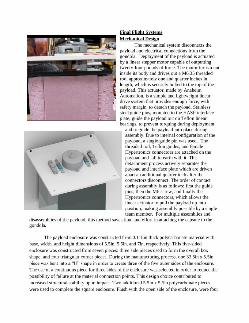
The payload enclosure was constructed from 0.118in thick polycarbonate material with
base, width, and height dimensions of 5.5in, 5.5in, and 7in, respectively. This five-sided
enclosure was constructed from seven pieces: three side pieces used to form the overall box
shape, and four triangular corner pieces. During the manufacturing process, one 33.5in x 5.5in
piece was bent into a “U” shape in order to create three of the five outer sides of the enclosure.
The use of a continuous piece for three sides of the enclosure was selected in order to reduce the
possibility of failure at the material connection points. This design choice contributed to
increased structural stability upon impact. Two additional 5.5in x 5.5in polycarbonate pieces
were used to complete the square enclosure. Flush with the open side of the enclosure, were four
triangular corner pieces that were constructed from the same polycarbonate material. These
corner pieces resembled 45 -45 -90 triangles with sides of 1.5in and a hypotenuse of 2.121in;
each piece is 1.0in deep. Eight 4-40 screws, two in each corner piece, were used to secure the top
plate to the payload enclosure. Each of the corner pieces also contained an attachment point for
the parachute clasps. To reduce the effects of solar heating, the enclosure was painted with white
Krylon Fusion for Plastic spray paint, which has an emissivity coefficient of 0.992.
Commercial Intel series solid state drives were mounted to two sides of the box. The
communication system was mounted to the third side, and the battery mounted to the bottom of
the box to locate the CG near the bottom on the payload. The top of the box was made of PVC
material and housed the pin attachment to the motor and the parachute brackets. The top of the
box was removed to access the internals of the payload. One antenna for the communication
system protruded from the bottom of the box. The antenna had one bend point. Based on
analysis of the landing of the 2010 prototype payload, the antenna had no protection from
impact. No damage was found on crush pad used in the previous design iteration, therefore it
was determined that the antenna would survive landing without additional impact protection. A
parachute tube passed through the HASP plate and stored the 24” parachute. The estimated
descent rate of the capsule was 17 ft/s. There were no significant issues encountered with the
Stratopigeon III payload mechanical and structural design. The payload deployed as expected
during thermal chamber testing, bench testing, and during the 2012 HASP flight. The payload
structure handled thermal and stress loads during thermal-vac testing and flight testing without
deformation or cracking, as much as can be seen from the flight data.
Electrical Systems Final Design
Overview
The electronics systems in the data capsule were designed to be simple and compatible
with already existing systems on scientific research payloads. Input from the CREAM Antarctic
payload was used to determine requirements for the electronic interfaces to the data capsule.
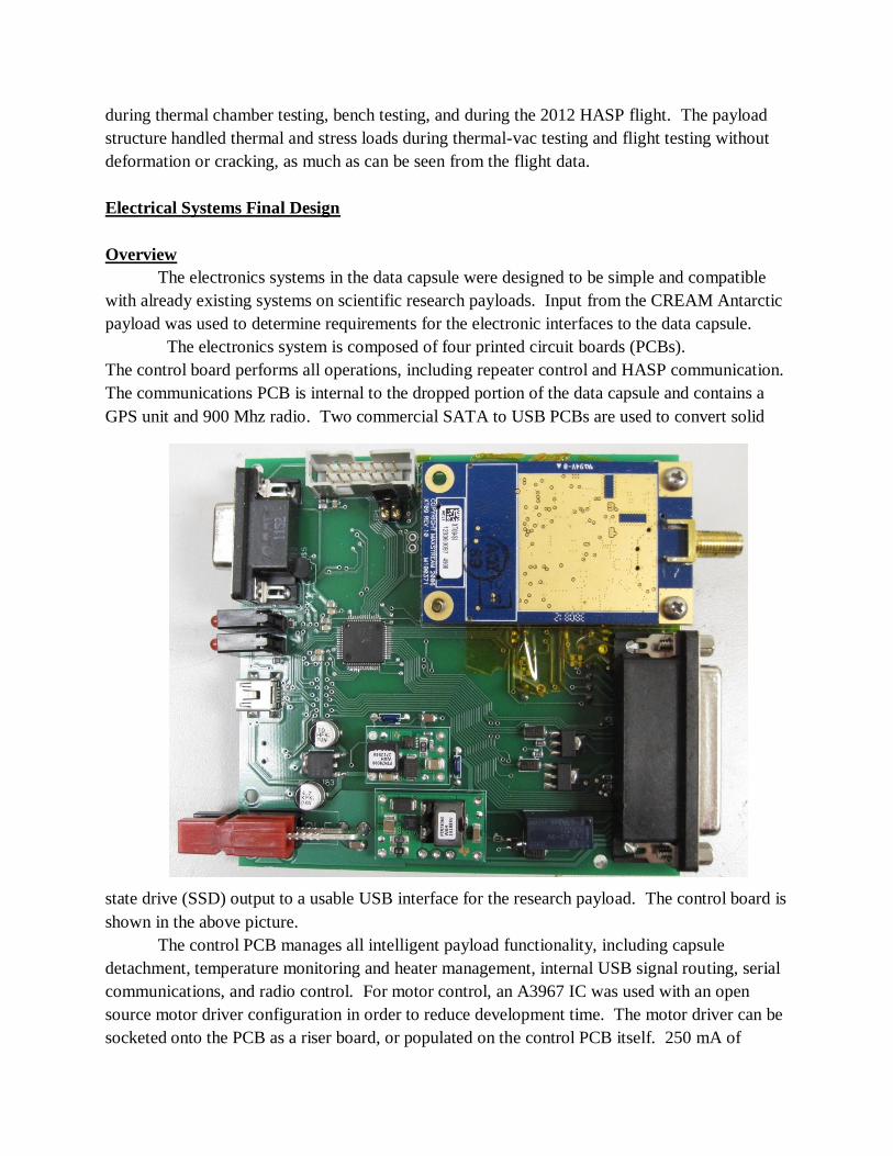
The electronics system is composed of four printed circuit boards (PCBs).
The control board performs all operations, including repeater control and HASP communication.
The communications PCB is internal to the dropped portion of the data capsule and contains a
GPS unit and 900 Mhz radio. Two commercial SATA to USB PCBs are used to convert solid
state drive (SSD) output to a usable USB interface for the research payload. The control board is
shown in the above picture.
The control PCB manages all intelligent payload functionality, including capsule
detachment, temperature monitoring and heater management, internal USB signal routing, serial
communications, and radio control. For motor control, an A3967 IC was used with an open
source motor driver configuration in order to reduce development time. The motor driver can be
socketed onto the PCB as a riser board, or populated on the control PCB itself. 250 mA of

current at HASP voltage was used to power the motor driver and drive the stepper motor for
payload detachment.
The control IC is a Texas Instruments MSP430. This IC controls all on board
functionality and contains all software needed to run the data capsule. The MSP430 was selected
for its low power, high capability structure needed to run all aspects of the data capsule within
the given low power requirements.
Thermal regulation is managed by the control PCB with four temperature sensors and
three flexible Kapton heaters. Heater power is sourced directly from the HASP voltage and
controlled with DPDT latching relays. Thermistors are co-located with each heater to ensure
reliable temperature management.
On board power management at the control board is implemented with two PTN78000
DC/DC switching regulators. Each regulator outputs a maximum of 1.5A at 5V and 3.3V for
various components in the payload subsystems.
The control PCB also contains the interface to external science payloads through two
micro-usb ports on the edge of the PCB. USB was selected as the capsule external interface in
order to minimize software changes on the target research payload, given that each research
payload already contains software to interface with attached hard drives. Therefore, a USB
interface allows for easier and faster integration with the data capsule. Because SATA to USB
conversion is a challenging electrical interface, commercial converters were used with each of
the SSDs.
The USB to SATA interface and data storage capacity of the data capsule was tested with
an external Linux computer prior to the HASP 2012 flight in the UMD test lab. However, due to
a lack of a suitable simulated research payload, this interface and functionality was not tested on
the actual 2012 flight.
Commercial SSDs provide a cheap and easily accessible data storage method for large
amounts of data. However, as commercial devices, there are temperature limitations that
preclude the use of commercial SSDs in extreme environments. In order to mitigate cold
temperature requirements, a heater and thermistor were attached to each SSD, in addition to a
metal heat spreader plate. Each drive was monitored by the payload and heated automatically as
needed during the flight.
The communications PCB inside the data capsule consisted of power regulation, Digi
Xtend 900 Mhz radio, and Lassen IQ GPS. The GPS was programmed externally to transmit one
GPGGA string every 15 seconds to the radio. A PTN78000 was used to regulate power to the
communications from the 9.6V LiPO4 battery. With 1 W of transmit power, the payload was
designed to have a battery life of approximately 12 hours.
Line of sight communications to a base station with a low power payload at a distance
and on the ground is challenging without any intermediary repeaters. In Antarctica, where there
are no repeaters available for use, a different method of receiving signals at the base station is
required. The control board of the Stratopigeon payload contains a repeating radio to solve this
problem by using the balloon itself as a repeater.
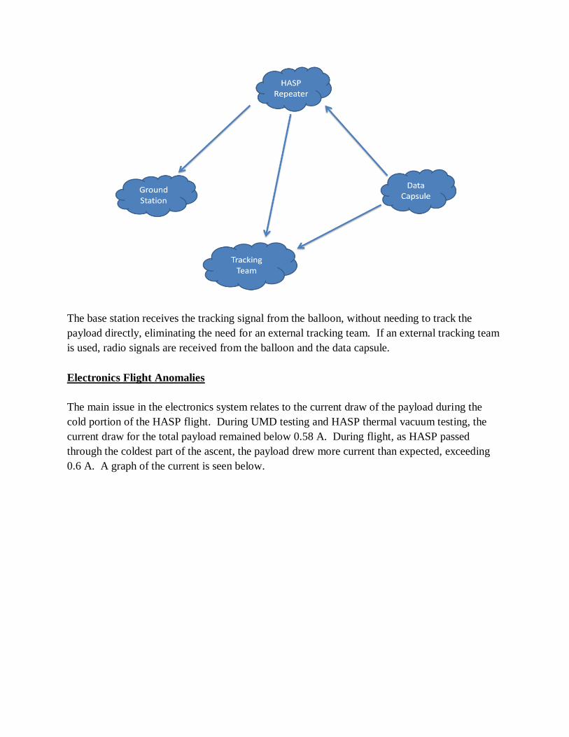
The base station receives the tracking signal from the balloon, without needing to track the
payload directly, eliminating the need for an external tracking team. If an external tracking team
is used, radio signals are received from the balloon and the data capsule.
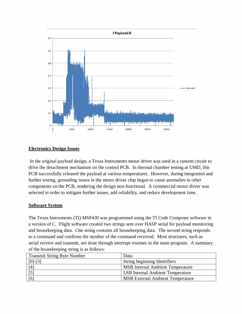
Electronics Flight Anomalies
The main issue in the electronics system relates to the current draw of the payload during the
cold portion of the HASP flight. During UMD testing and HASP thermal vacuum testing, the
current draw for the total payload remained below 0.58 A. During flight, as HASP passed
through the coldest part of the ascent, the payload drew more current than expected, exceeding
0.6 A. A graph of the current is seen below.
Electronics Design Issues
In the original payload design, a Texas Instruments motor driver was used in a custom circuit to
drive the detachment mechanism on the control PCB. In thermal chamber testing at UMD, this
PCB successfully released the payload at various temperatures. However, during integration and
further testing, grounding issues in the motor driver chip began to cause anomalies in other
components on the PCB, rendering the design non-functional. A commercial motor driver was
selected in order to mitigate further issues, add reliability, and reduce development time.
Software System
The Texas Instruments (TI) MSP430 was programmed using the TI Code Composer software in
a version of C. Flight software created two strings sent over HASP serial for payload monitoring
and housekeeping data. One string contains all housekeeping data. The second string responds
to a command and confirms the number of the command received. Most structures, such as
serial receive and transmit, are done through interrupt routines in the main program. A summary
of the housekeeping string is as follows:
Transmit String Byte Number Data
[0]-[3] String beginning Identifiers
[4] MSB Internal Ambient Temperature
[5] LSB Internal Ambient Temperature
[6] MSB External Ambient Temperature
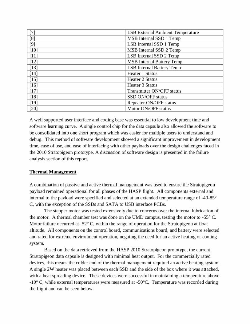
[7] LSB External Ambient Temperature
[8] MSB Internal SSD 1 Temp
[9] LSB Internal SSD 1 Temp
[10] MSB Internal SSD 2 Temp
[11] LSB Internal SSD 2 Temp
[12] MSB Internal Battery Temp
[13] LSB Internal Battery Temp
[14] Heater 1 Status
[15] Heater 2 Status
[16] Heater 3 Status
[17] Transmitter ON/OFF status
[18] SSD ON/OFF status
[19] Repeater ON/OFF status
[20] Motor ON/OFF status
A well supported user interface and coding base was essential to low development time and
software learning curve. A single control chip for the data capsule also allowed the software to
be consolidated into one short program which was easier for multiple users to understand and
debug. This method of software development showed a significant improvement in development
time, ease of use, and ease of interfacing with other payloads over the design challenges faced in
the 2010 Stratopigeon prototype. A discussion of software design is presented in the failure
analysis section of this report.
Thermal Management
A combination of passive and active thermal management was used to ensure the Stratopigeon
payload remained operational for all phases of the HASP flight. All components external and
internal to the payload were specified and selected at an extended temperature range of -40-85°
C, with the exception of the SSDs and SATA to USB interface PCBs.
The stepper motor was tested extensively due to concerns over the internal lubrication of
the motor. A thermal chamber test was done on the UMD campus, testing the motor to -55° C.
Motor failure occurred at -52° C, within the range of operation for the Stratopigeon at float
altitude. All components on the control board, communications board, and battery were selected
and rated for extreme environment operation, negating the need for an active heating or cooling
system.
Based on the data retrieved from the HASP 2010 Stratopigeon prototype, the current
Stratopigeon data capsule is designed with minimal heat output. For the commercially rated
devices, this means the colder end of the thermal management required an active heating system.
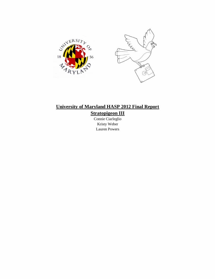
A single 2W heater was placed between each SSD and the side of the box where it was attached,
with a heat spreading device. These devices were successful in maintaining a temperature above
-10° C, while external temperatures were measured at -50°C. Temperature was recorded during
the flight and can be seen below.
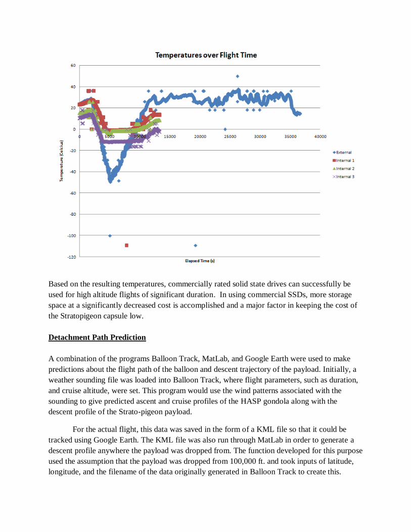
Based on the resulting temperatures, commercially rated solid state drives can successfully be
used for high altitude flights of significant duration. In using commercial SSDs, more storage
space at a significantly decreased cost is accomplished and a major factor in keeping the cost of
the Stratopigeon capsule low.
Detachment Path Prediction
A combination of the programs Balloon Track, MatLab, and Google Earth were used to make
predictions about the flight path of the balloon and descent trajectory of the payload. Initially, a
weather sounding file was loaded into Balloon Track, where flight parameters, such as duration,
and cruise altitude, were set. This program would use the wind patterns associated with the
sounding to give predicted ascent and cruise profiles of the HASP gondola along with the
descent profile of the Strato-pigeon payload.
For the actual flight, this data was saved in the form of a KML file so that it could be
tracked using Google Earth. The KML file was also run through MatLab in order to generate a
descent profile anywhere the payload was dropped from. The function developed for this purpose
used the assumption that the payload was dropped from 100,000 ft. and took inputs of latitude,
longitude, and the filename of the data originally generated in Balloon Track to create this.
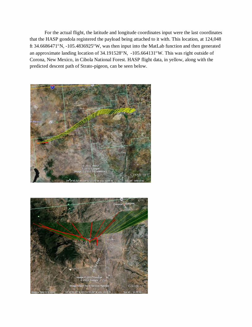
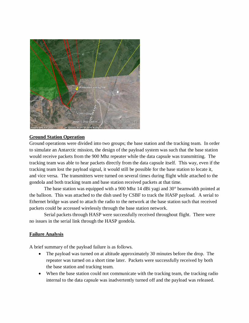
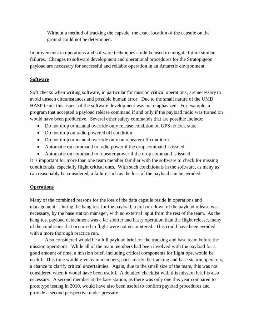
For the actual flight, the latitude and longitude coordinates input were the last coordinates
that the HASP gondola registered the payload being attached to it with. This location, at 124,048
ft 34.6686471N, -105.4836925W, was then input into the MatLab function and then generated
an approximate landing location of 34.191528N, -105.664131W. This was right outside of
Corona, New Mexico, in Cibola National Forest. HASP flight data, in yellow, along with the
predicted descent path of Strato-pigeon, can be seen below.
Ground Station Operation
Ground operations were divided into two groups; the base station and the tracking team. In order
to simulate an Antarctic mission, the design of the payload system was such that the base station
would receive packets from the 900 Mhz repeater while the data capsule was transmitting. The
tracking team was able to hear packets directly from the data capsule itself. This way, even if the
tracking team lost the payload signal, it would still be possible for the base station to locate it,
and vice versa. The transmitters were turned on several times during flight while attached to the
gondola and both tracking team and base station received packets at that time.
The base station was equipped with a 900 Mhz 14 dBi yagi and 30° beamwidth pointed at
the balloon. This was attached to the dish used by CSBF to track the HASP payload. A serial to
Ethernet bridge was used to attach the radio to the network at the base station such that received
packets could be accessed wirelessly through the base station network.
Serial packets through HASP were successfully received throughout flight. There were
no issues in the serial link through the HASP gondola.
Failure Analysis
A brief summary of the payload failure is as follows.
The payload was turned on at altitude approximately 30 minutes before the drop. The
repeater was turned on a short time later. Packets were successfully received by both
the base station and tracking team.
When the base station could not communicate with the tracking team, the tracking radio
internal to the data capsule was inadvertently turned off and the payload was released.
Without a method of tracking the capsule, the exact location of the capsule on the
ground could not be determined.
Improvements in operations and software techniques could be used to mitigate future similar
failures. Changes to software development and operational procedures for the Stratopigeon
payload are necessary for successful and reliable operation in an Antarctic environment.
Software
Soft checks when writing software, in particular for mission critical operations, are necessary to
avoid unseen circumstances and possible human error. Due to the small nature of the UMD
HASP team, this aspect of the software development was not emphasized. For example, a
program that accepted a payload release command if and only if the payload radio was turned on
would have been productive. Several other safety commands that are possible include:
Do not drop or manual override only release condition on GPS no lock state
Do not drop on radio powered off condition
Do not drop or manual override only on repeater off condition
Automatic on command to radio power if the drop command is issued
Automatic on command to repeater power if the drop command is issued
It is important for more than one team member familiar with the software to check for missing
conditionals, especially flight critical ones. With such conditionals in the software, as many as
can reasonably be considered, a failure such as the loss of the payload can be avoided.
Operations
Many of the combined reasons for the loss of the data capsule reside in operations and
management. During the hang test for the payload, a full run-down of the payload release was
necessary, by the base station manager, with no external input from the rest of the team. As the
hang test payload detachment was a far shorter and hasty operation than the flight release, many
of the conditions that occurred in flight were not encountered. This could have been avoided
with a more thorough practice run.
Also considered would be a full payload brief for the tracking and base team before the
mission operations. While all of the team members had been involved with the payload for a
good amount of time, a mission brief, including critical components for flight ops, would be
useful. This time would give team members, particularly the tracking and base station operators,
a chance to clarify critical uncertainties. Again, due to the small size of the team, this was not
considered when it would have been useful. A detailed checklist with this mission brief is also
necessary. A second member at the base station, as there was only one this year compared to
prototype testing in 2010, would have also been useful to confirm payload procedures and
provide a second perspective under pressure.
Lack of communication between the base station and tracking team also caused payload
recovery to be unsuccessful. Because both teams would be receiving payload location, it was
thought that cell phone coverage would be sufficient to pass critical information. During the
flight, cell phone coverage was inadequate for the task required. A different, more reliable
method of exchanging information is strongly recommended for future operation, even further
than the ham radio used in 2010, also somewhat unreliable. A satellite phone or other method of
radio communication would be useful.
A list of suggested operations improvements are the following.
Detailed mission brief before the flight
Detailed checklist for tracking and base station teams
Full run through of payload procedures during hang-test by the base station team only
Reliable communications method between base station and tracking team
Flight checklist, for pre-flight and during flight ops
Two team members each for the tracking and base station teams
Future Work
The Stratopigeon concept is an important supplement to current Antarctic ballooning techniques
and has great value for ULDB flights. Further design development can improve this value
extensively. In continuing payload development, the Stratopigeon team suggests the following:
A water-landing payload. Dropping the payload over land, as in its current design, is
limiting in where the payload can be released. A payload that can be released over water
and retrieved by boat expands the operational capacity of the capsule.
New sizing: Digi now makes very small radios that can perform all the functions of those
used in the 2012 test. Combined with large amounts of storage now available in very
small packages (micro-sd cards for example), the Stratopigeon payload could be reduced
to the size of a pack of cards.
Improved universal interface to research payloads. Given that each research payload is
different and has different data storage needs, a universal easy to use data interface to the
Stratopigeon payload is required.