Embed Size (px)
Citation preview
t,-
UNIVERSITY of MARYLAND
WALKING ROBOT:
A DESIGN PROJECT
for
UNDERGRADUATE STUDENTS
Student Participants:
Bob Oisen*.Jim Bielec
Dave HartsigMani Oliva
DRIVELINE GROUP:
Phil Grotheer*Morad HekmatDavid RussellHossein Tavakoli
Gary Young
CHASSIS & BIGFOOT:
Tom Nave*Tim CondonLisa Fenwick-Steen
CONTROL HARDWARE:
John Neubert*
Art DunningLadan KimiayiTed Mc CordTom Richmond
George Ryan
CONTROL SOFTWARE:
Danny Sachs*Bob Hails
Darya NabvianTim Strenka
Tej Rehncy
*Group Leaders appear in Bold
Faculty Advisors: Shapour AzarmLung Wen Tsai
Teach)ng Assistant: Mark Uebel(NA_A-CR-Io683V) U_iV_trY nF MARYLANn
WALKING R_B_T: A OESI_N PPGJkCT F_R
UNDERGRADUATE STUDENTS (Maryland Univ.)
130 p CSCL
\
NoO-Z_3_i
13I Unclas
G3/57 0295000
https://ntrs.nasa.gov/search.jsp?R=19900017015 2018-07-27T23:09:58+00:00Z
l
i.
TABLE of CONTENTS
ABSTRACT ............................................................................... 1
INTRODUCTION ........................................................................ 1
CHASSIS and BIGFOOT. ............................................................... 1
DRIVELINE ............................................................................... 2
LEGS ....................................................................................... 3
CONTROL HARDWARE ................................................................ 4
CONTROL SOD'TWA RE ...................................................... ,.., .... ... 5
CONCLUSION ............................................................................ 6
ACKNOWLEDGEMENTS ............................................................... 7
APPENDIX A: CHASSIS
APPENDIX B: DRIVELINE
APPENDIX C: LEGS
APPENDIX D: CONTROL HARDWARE
APPENDIX E: CONTROL SOFTWARE
APPENDIX F: MARTIAN CONSIDERATIONS
ABSTRACT
The design and construction of the University of Maryland walking machine was-completed during the 1989-1990 academic year. It was required that the machine be capable ofcompleting a number of tasks including walking in a straight line, turn to change direction, andmaneuver over an obstacle such as a set of stairs. The machine consists of two sets of four
telescoping legs that alternately support the entire structure. A gear-box and crank-arm assembly isconnected to the leg sets to provide the power required for the translational motion of the machine.By retracting all eight legs, the robot comes to rest on a central 'JBigfoot _' support. Turning isaccomplished by rotating the machine about this support. The machine can be controlled by usingeither a user operated remote tether or the on-board computer for the execution of controlcommands. Absolute encoders are attached to all motors (leg, main drive, and Bigfoot) to provide
the control computer with information regarding the status of the motors (up-down motion,forward or reverse rotation). Long and short range infrared sensors provide the computer withfeedback information regarding the machine's relative position to a series of stripes and reflectors.These infrared sensors simulate how the robot might sense and gain information about theenvironment of Mars.
INTRODUCTION
The University of Maryland walking machine, Prototerp IV, was designed to be a MartianPlanetary Rover. Among the design requirements were that the machine be able to support itself ona set of movable legs and not depend on rollers or wheels for its maneuverability. In addition, itwas required that the machine be able to "walk" in a straight line and turn to change the direction ofmotion. These requirements allows the machine to follow any path as well as walk over anirregular surface. The University of Maryland Planetary Rover has the capability to obtain controlfeedback information regarding its immediate environment thus the machine has the ability to
autonomously compute any desired and obtainable path.The machine was designed and built by the senior Mechanical and Electrical Engineering
students of ENME 408 over the two semester period of the 1989-1990 academic year. Themotivation behind building Prototerp IV was to provide the students with practical experience sothey may improve and refine their engineering skills by combining their talents as they worktoward a common goal. In addition, It is the purpose of this project to provide an environmentwhere the students learn about robotic systems and apply their creativity toward the constructionof their walking machine.
Prototerp IV required two semesters to evolve. The machine was designed in the Fall of1989, and construction was completed in the Spring of 1990. For both semesters, the students
were divided into groups which were to address a particular aspect of the project.In the first semester, the students proposed the initial design. There were four groups: (i)
the chassis group, which was responsible for the chassis, drive-line, and the Bigfoot (ii) the leggroup, which was responsible for the designing of the legs, (iii) the control group, which wasresponsible for the control hardware and software as well as the selection of all motors, and (iv)the sensors group, which was responsible for the selection of rotation, position and visionsensors.
In the second semester, the students were responsible for the actual construction of the
walking machine. As in the first semester, the students were split into groups which wereresponsible for reviewing the design proposal of the previous semester and to suggest changes toimprove the overall design of the machine. There were five groups involved during the secondsemester: (i) the chassis and Bigfoot group, (ii) the leg group, (iii) the drive-line group, (iv) thecontrol hardware group, and (v) the control software group.
CHASSIS AND BIGFOOT
The chassis of Prototerp IV provides a rigid support to which all other components are
attached. Primary considerations for the chassis design include durability, functionality, weight,
balance, and safety (Appendix A).Many materials were considered for the design of the chassis. Preliminary calculations
indicated that the robot would weigh approximately 150 pounds. In order to prevent bending orflexing along the length or width of the chassis, it was determined that a 2" X 3" 1024 aluminumbox channel would be best suited to fulfill the requirements (Shigley, 1989). The advantages ofusing aluminum include its high strength-to-weight ratio and the ease with which it can be
machined to proper dimensions.The overall shape of the body resembles a composite I-beam. To allow for the placement
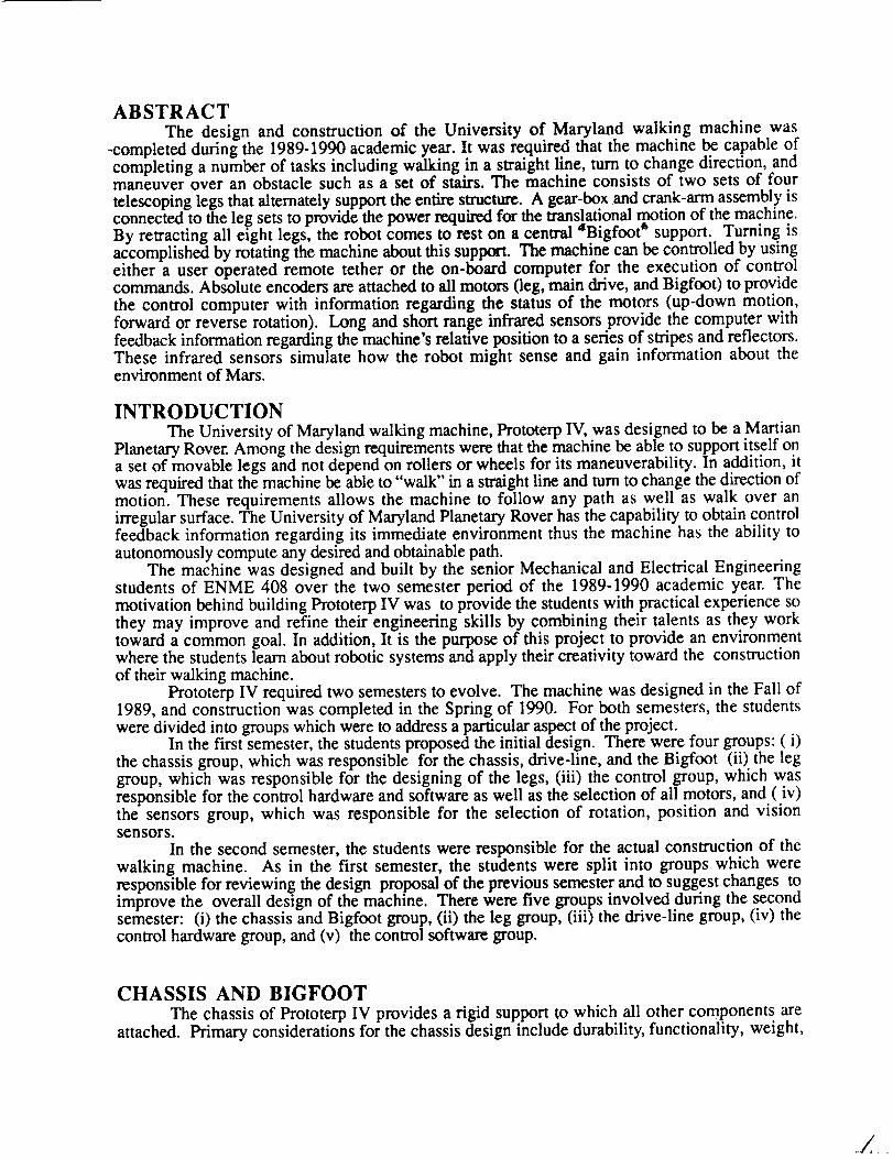
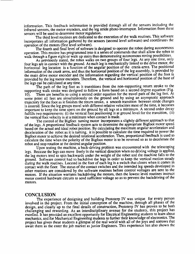
of the gearbox, crank assemblies, computer, and power-packs, the web of the composite I-beam ismade of two sections of box channel separated by a distance of 11". Mounted on the outer edgeof each web section, near the center, are two leg assembly slider rod support brackets (Fig. 1).Initially, these support brackets were to be a single piece of aluminum channel that bisected theweb at the midpoint. This effectively cut the chassis into two pieces. It was then determined thatthis design would significantly reduce the rigidity of the robot which could result in buckling andfailure. Upon review, it was decided that the best approach was for the web sections to becontinuous, and have the slider rod support brackets and slider rods mounted directly to them.
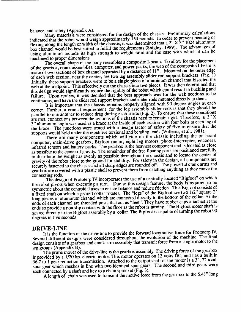
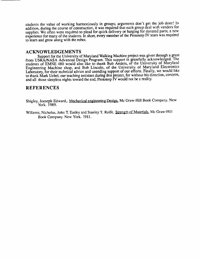
It is important that the chassis remains properly aligned with 90 degree angles at eachcorner. Further, a crucial requirement for the leg assembly slider rods is that they should beparallel to one another to reduce drag during each stride (Fig. 2). To ensure that these conditionsare met, connections between the sections of the chassis need to remain rigid. Therefore, a 3" X3" aluminum angle was used as a brace at the inside of each section with four bolts at each leg ofthe brace. The junctions were tested with a design factor of safety of five to ensure that thesupports would hold under the repetitive torsional and bending loads (Willems, et al., 1981).
There are many components which will ride on the chassis including the on-boardcomputer, main-drive gearbox, Bigfoot motor, eight leg motors, photo-interrupter, encoders,infrared sensors and battery-packs. The gearbox is the heaviest component and is located as closeas possible to the center of gravity. The remainder of the free floating parts are positioned carefullyto distribute the weight as evenly as possible throughout the chassis and to locate the center ofgravity of the robot close to the ground for stability. For safety in the design, all components aresecurely fastened to the chassis and all sharp edges are rounded off. The powerful crank arms andgearbox are covered with a plastic shell to prevent them from catching anything as they move theconnecting rods.
The design of Prototerp IV incorporates the use of a centrally located "Bigfoot" on whichthe robot pivots when executing a turn. Due to this design feature, the body is required to besymmetric about the centroidal axes to ensure balance and reduce friction. This Bigfoot consists ofa fixed shaft on which a geared collar rotates. The "legs" of the Bigfoot are two 1/2" square 2'long pieces of aluminum channel which are connected directly to the bottom of the collar. At theends of each channel are threaded posts that act as "feet". They have rubber caps attached at theends so provide a non slip contact with the floor as the robot is turning. The Bigfoot motor shaft isgeared directly to the Bigfoot assembly by a collar. The Bigfoot is capable of turning the robot 90degrees in five seconds.
DRIVE-LINEIt is the function of the drive-line to provide the forward locomotive force for Prototerp IV.
Several different designs were considered throughout the evolution of the machine. The finaldesign consists of a gearbox and crank-arm assembly that transmit force from a single motor to theleg groups (Appendix B).
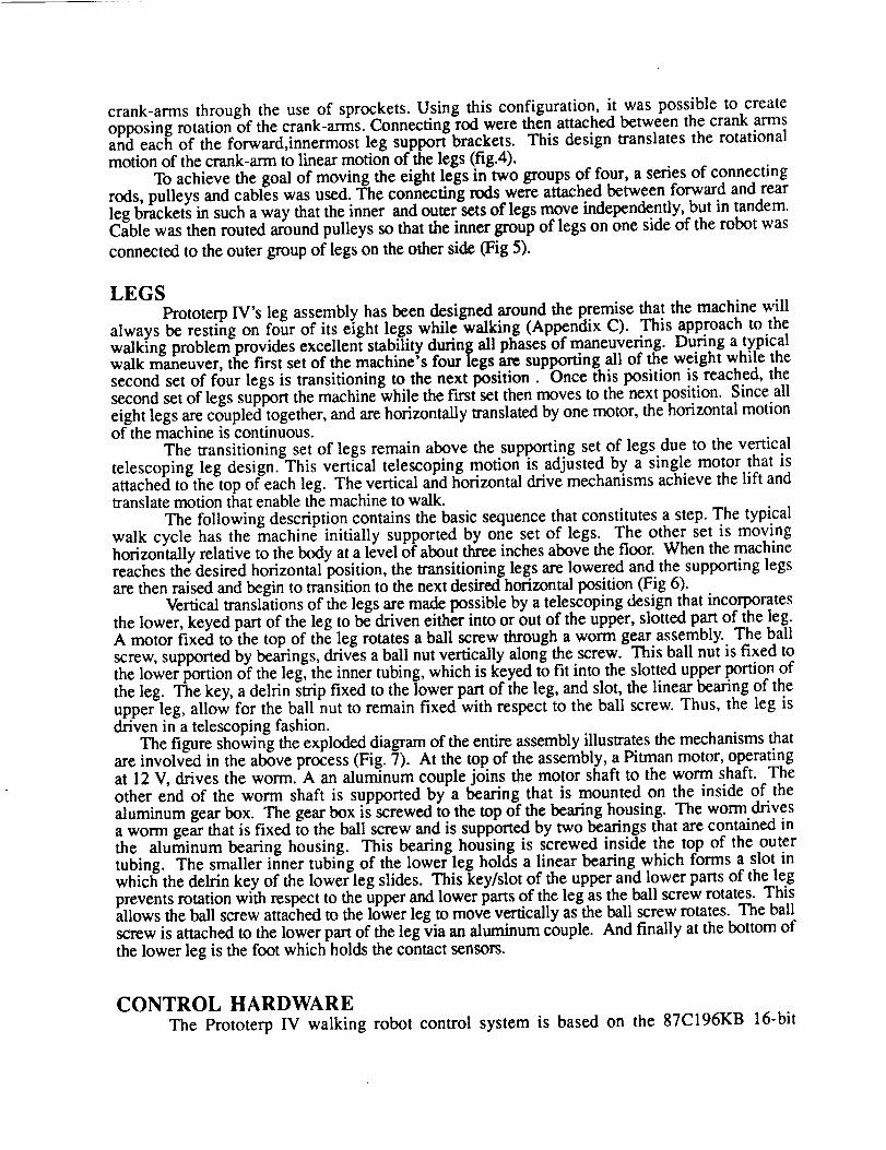
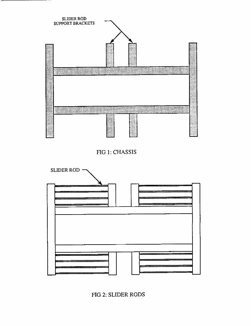
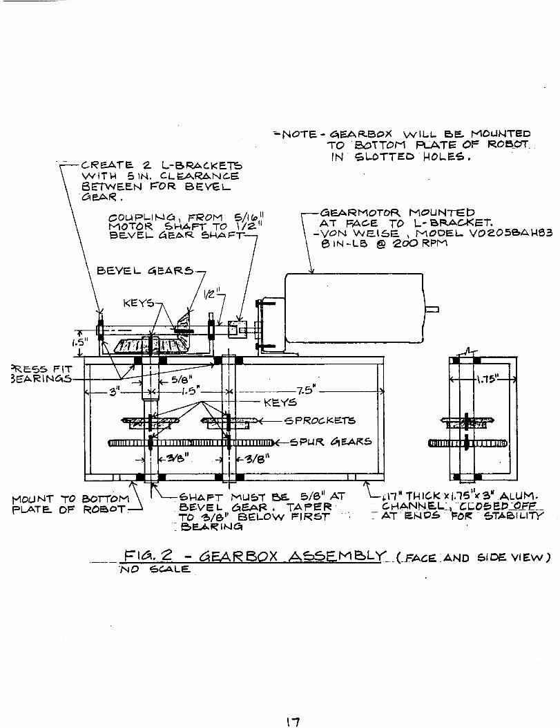
The prime mover of the drive-line is the gearbox assembly. The driving force of the gearboxis provided by a 1/20 hp. electric motor. This motor operates on 12 volts DC, and has a built in36.7 to 1 gear reduction transmission. Attached to the output shaft of the motor is a 3", 72 toothspur gear which meshes in line with two identical spur gears. The second and third gears wereeach connected by a shaft and key to a chain sprocket (Fig. 3).
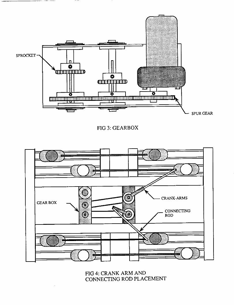
A length of chain was used to transmit the motive force from the gearbox to the 5.41" long
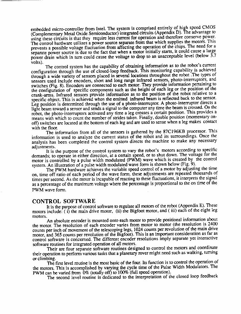
crank-arms through the use of sprockets. Using this configuration, it was possible to createopposing rotation of the crank-arms. Connecting rod were then attached between the crank armsand each of the forward,innermost leg support brackets. This design translates the rotationalmotion of the crank-arm to linear motion of the legs (fig.4).
To achieve the goal of moving the eight legs in two groups of four, a series of connectingrods, pulleys and cables was used. The connecting rods were attached between forward and rearleg brackets in such a way that the inner and outer sets of legs move independently, but in tandem.Cable was then routed around pulleys so that the inner group of legs on one side of the robot was
connected to the outer group of legs on the other side (Fig 5).
LEGSPrototerp IV's leg assembly has been designed around the premise that the machine will
always be resting on four of its eight legs while walking (Appendix C). This approach to thewalking problem provides excellent stability during all phases of maneuvering. During a typicalwalk maneuver, the first set of the machine's four legs are supporting all of the weight while thesecond set of four legs is transitioning to the next position. Once this position is reached, thesecond set of legs support the machine while the fast set then moves to the next position. Since alleight legs are coupled together, and are horizontally translated by one motor, the horizontal motionof the machine is continuous.
The transitioning set of legs remain above the supporting set of legs due to the verticaltelescoping leg design. This vertical telescoping motion is adjusted by a single motor that isattached to the top of each leg. The vertical and horizontal drive mechanisms achieve the lift andtranslate motion that enable the machine to walk.
The following description contains the basic sequence that constitutes a step. The typicalwalk cycle has the machine initially supported by one set of legs. The other set is movinghorizontally relative to the body at a level of about three inches above the floor. When the machinereaches the desired horizontal position, the transitioning legs are lowered and the supporting legsare then raised and begin to transition to the next desired horizontal position (Fig 6).
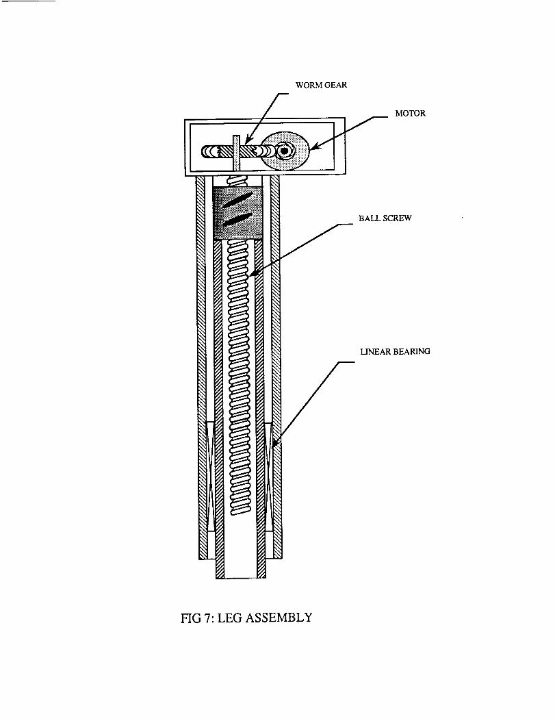
Vertical translations of the legs are made possible by a telescoping design that incorporatesthe lower, keyed part of the leg to be driven either into or out of the upper, slotted part of the leg.A motor fixed to the top of the leg rotates a ball screw through a worm gear assembly. The ballscrew, supported by bearings, drives a ball nut vertically along the screw. This ball nut is fixed tothe lower portion of the leg, the inner tubing, which is keyed to fit into the slotted upper portion ofthe leg. The key, a delrin strip fixed to the lower part of the leg, and slot, the linear bearing of theupper leg, allow for the ball nut to remain fixed with respect to the ball screw. Thus, the leg isdriven in a telescoping fashion.
The figure showing the exploded diagram of the entire assembly illustrates the mechanisms thatare involved in the above process (Fig. 7). At the top of the assembly, a Pitman motor, operatingat 12 V, drives the worm. A an aluminum couple joins the motor shaft to the worm shaft. Theother end of the worm shaft is supported by a bearing that is mounted on the inside of thealuminum gear box. The gear box is screwed to the top of the bearing housing. The worm drivesa worm gear that is fixed to the ball screw and is supported by two bearings that are contained inthe aluminum bearing housing. This bearing housing is screwed inside the top of the outertubing. The smaller inner tubing of the lower leg holds a linear bearing which forms a slot inwhich the delrin key of the lower leg slides. This key/slot of the upper and lower parts of the legprevents rotation with respect to the upper and lower parts of the leg as the ball screw rotates. Thisallows the ball screw attached to the lower leg to move vertically as the ball screw rotates. The ballscrew is attached to the lower part of the leg via an aluminum couple. And finally at the bottom ofthe lower leg is the foot which holds the contact sensors.
CONTROL HARDWAREThe Prototerp IV walking robot control system is based on the 87C196KB 16-bit
embeddedmicro-controller from Intel. The system is comprised entirely of high speed CMOS(Complementary Metal Oxide Semiconductor) integrated circuits (Appendix D). The advantage tousing these circuits is that they require less current for operation and therefore conserve power.The control hardware utilizes a power source separate from that which supplies the motors. Thisprevents a possible voltage fluctuation from affecting the operation of the chips. The need for aseparate power source is due to the fact that when a motor initially starts, it could cause a largepower drain which in turn could cause the voltage to drop to an unacceptable level (below 3.7volts).
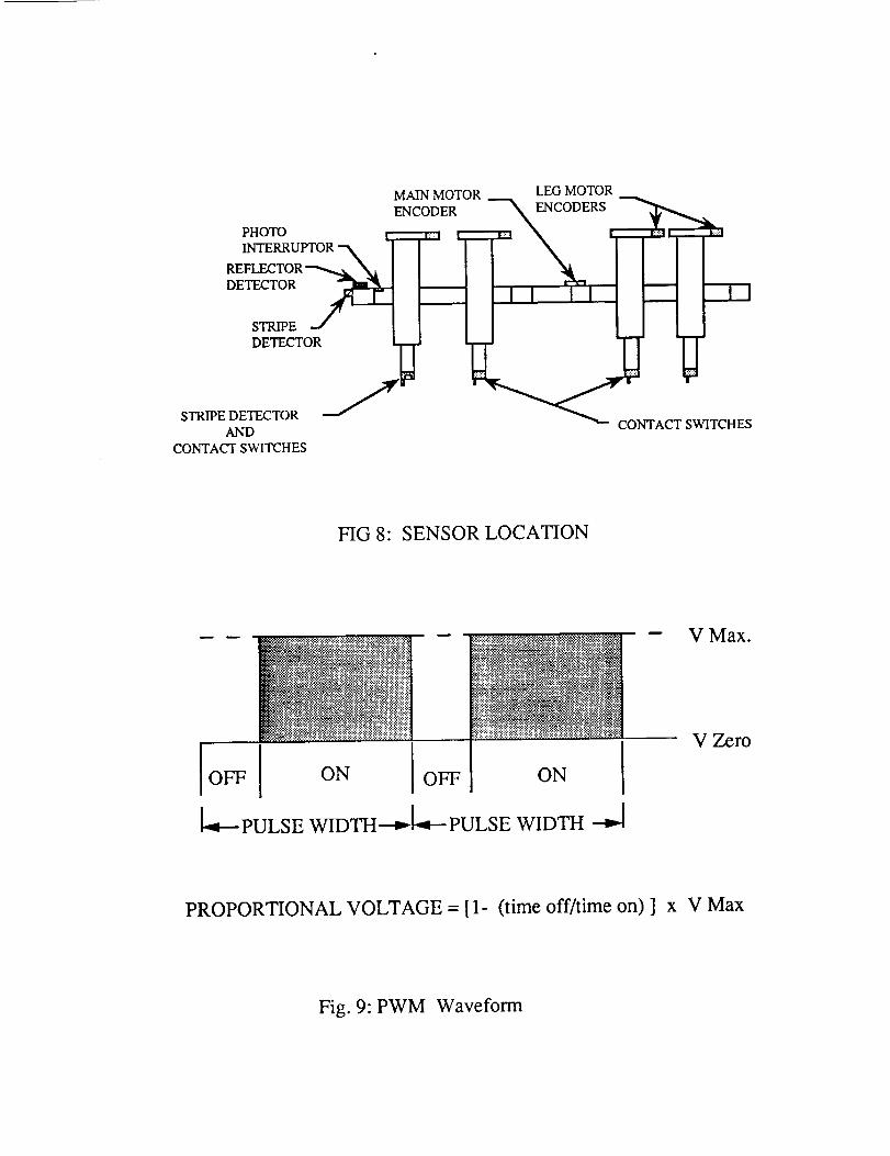
The control system has the capability of obtaining information as to the robot's currentconfiguration through the use of closed-loop feedback. This monitoring capability is achievedthrough a wide variety of sensors placed in several locations throughout the robot .The types ofsensors used include encoders, short and long range infrared sensors, photo-interruptors, andswitches (Fig. 8). Encoders are connected to each motor. They provide information pertaining tothe configuration of specific components such as the height of each leg or the position of thecrank-arms. Infrared sensors provide information as to the position of the robot relative to aspecific object. This is achieved when the emitted infrared beam is reflected back to the sensor.Leg position is determined through the use of a photo-interruptor. A photo-interruptor directs alight beam toward a sensor and sends a signal to the computer any time the beam is crossed. On therobot, the photo-interruptors activated any time a leg crosses a certain position. This provides ameans with which to count the number of strides taken. Finally, double position (momentary on-off) switches are located at the bottom of each leg and are used to sense when a leg makes contactwith the floor.
The information from all of the sensors is gathered by the 87C196KB processor. Thisinformation is used to analyze the current status of the robot and its surroundings. Once theanalysis has been completed the control system directs the machine to make any necessaryadjustments.
It is the purpose of the control system to vary the robot's motors according to specificdemands; to operate in either direction, at a certain speed, or to shut down. The voltage for themotor is controlled by a pulse width modulated (PWM) wave which is created by the controlsystem. An illustration of a pulse width modulated wave form is shown below (Fig. 9).
The PWM hardware achieves the variable speed control of a motor by adjusting the timeon, time off ratio of each period of the wave form. these adjustments are repeated thousands oftimes per second. As the motor is incapable of reacting to these fluctuations, it interprets the signal
as a percentage of the maximum voltage where the percentage is proportional to the on time of thePWM wave form.
CONTROL SOFTWAREIt is the purpose of control software to regulate all motors of the robot (Appendix E). These
motors include: (i) the main drive motor, (ii) the Bigfoot motor, and (iii) each of the eight legmotors.
An absolute encoder is mounted onto each motor to provide positional information aboutthe motor. The resolution of each encoder varies from motor to motor (the resolution is 2400counts per inch of movement of the telescoping legs, 1024 counts per revolution of the main drivemotor, and 365 counts per revolution of the Bigfoot). This is an important consideration as far ascontrol software is concerned. The different encoder resolutions imply separate yet interactivesoftware routines for integrated operation of all motors.
Their are four separate software routines designed to control the motors and coordinatetheir operation to perform various tasks that a planetary rover might need such as walking, turningor climbing.
The first level routine is the most basic of the four. Its function is to control the operation ofthe motors. This is accomplished by varying the cycle time of the Pulse Width Modulators. ThePWM can be varied from 0% (totally off) to 100% (full speed operation).
The second level routine is dedicated to the interpretation of the closed loop feedback
information. This feedback information is provided through all of the sensors including theinfrared sensors, the motor encoders, and the leg stride photo-interruptor. Information from these
sensors will be used to determine motor regulation.The third level routines are dedicated to the execution of the walk routines. This software
incorporates all information gathered by the sensors (second level software) and coordinates the
operation of the motors (first level software).The fourth and final level of software is designed to operate the robot during autonomous
operation. This routine has programmed into it a series of commands that shall allow the robot towalk through a figure eight or walk up stairs thus demonstrating autonomous roving possibilities.
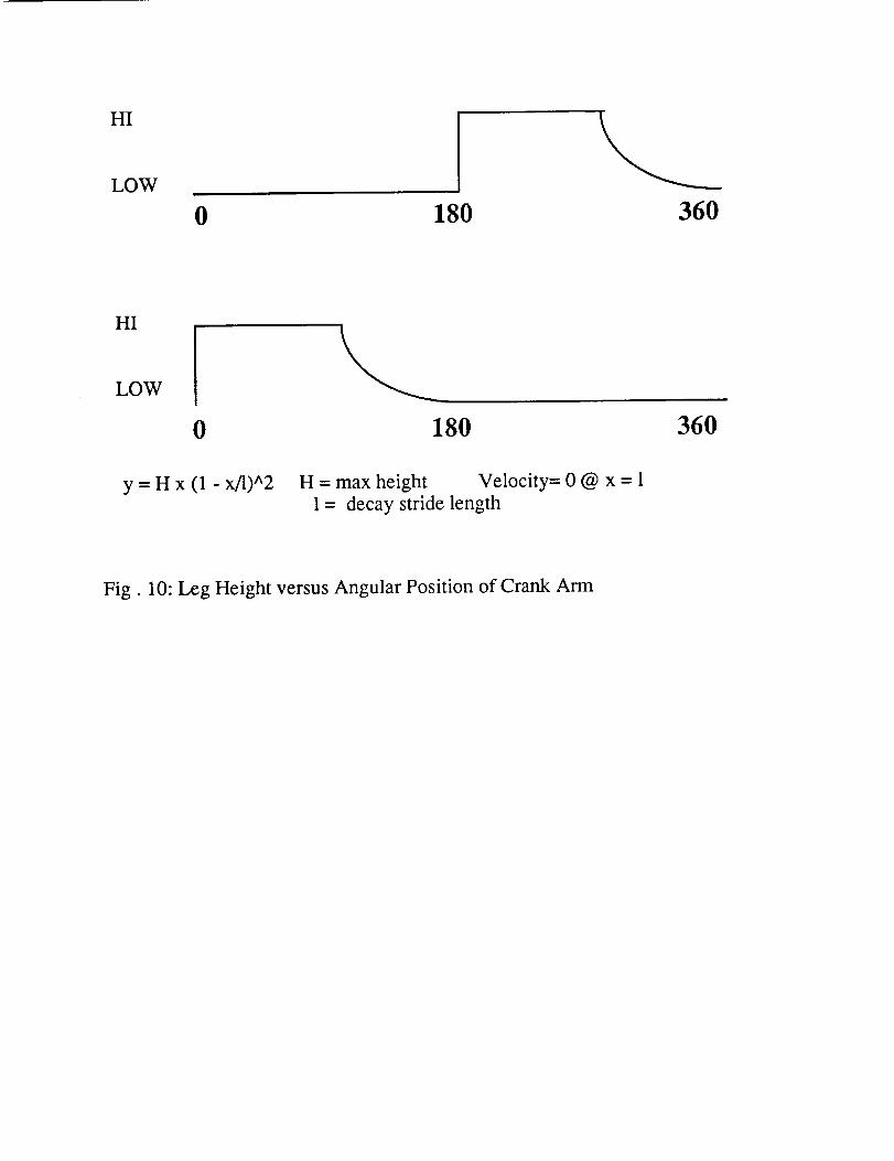
As previously stated, the robot walks on two groups of four legs. At any one time, onlyfour legs are in contact with the ground. As each leg is mechanically linked to the drive motor, thehorizontal leg location is a function of the angular position of the crank-arms. The positionalinformation of the crank arms, and thus the horizontal position of the leg assembly, is provided bythe main drive motor encoder and the information regarding the vertical position of the foot is
provided by the leg motor encoders. Therefore, the vertical and horizontal position of the base ofthe legs can be calculated at any time.
The path of the leg foot as it transitions from the non-supporting return stroke to thesupporting walk stroke was designed to follow a form based on a second degree equation (Fig.10). There are benefits to using a second order equation for the travel path of the leg feet. At
some point all feet are simultaneously on the ground and by using an asymptotic approachtrajectory for the foot as it finishes the return stroke, a smooth transition between stride changesis assured. Since the leg groups travel with different relative velocities most of the time, it becomes
important to keep the time spent on the ground by. all leg.s at a minimum. A second order decayfulfills two requirements: (i) the vertical foot posmoning is at ground level for the transition, (ii)the vertical foot velocity is at a minimum when contact is made.
The control of the Bigfoot turning motor incorporates a slightly different approach to thatof the legs. A proportional feedback system acts to determine the ap.propriate Bigfoot motor speedbased on the actual and ideal robot position. By calculating the maximum angular acceleration anddeceleration of the robot as it is turning, it is possible to calculate the time required to power the
Bigfoot motor to achieve the desired rotational acceleration. Then, proportional feedback is used tocalculate the time when the polarity of the Bigfoot motor is to be reversed so as to decelerate the
robot and stop rotation at the desired angular position.Upon testing the machine, a back-driving problem was encountered with the telescoping
legs. Because the legs can move freely in the vertical direction when no driving voltage is applied,the leg motors tend to spin backwards under the weight of the robot and the machine falls to theground. Software control had to backdrive the legs in order to keep the vertical motion steadyduring the walk routines. Located in the foot of each leg is a switch that closes when it comes incontact with the floor. The status of the contact switches and the intended leg speeds developed in
other routines are considered by the software routines before control voltages are sent to themotors. If the situation warrants backdriving the motors, then the lowest level routines instructmotor control hardware circuits to send sufficient voltage so as to prevent the backdriving of the
motors.
CONCLUSIONThe experience of designing and building Prototerp IV was unique for every person
involved in the project. From the initial conception of the machine, through all phases of thedesign, and clearly up to the final details of construction, Prototerp IV has proven to be bothchallenging and rewarding. As an interdisciplinary avenue for the students, this project hasexcelled. It has provided an excellent opportunity for Eleclrical Engineering students to learn aboutmechanics, and for Mechanical Engineering students to further their knowledge of electronics. The
project has given these students a glimpse of the real world with all of the joys and sorrows thatawait them as the enter the job market as junior Engineers. This experience has also shown the
• • ° ' ° V
students the value of working harmomously m groups; arguments don t get the job done. Inaddition, during the course of construction, it was required that each group deal with vendors forsupplies. We often were required to plead for quick delivery or barging for donated parts; a newexperience for many of the students. In short, every member of the Prototerp IV team was requiredto learn and grow along with the robot.
AC KNOWLEDGEMENTSSupport for the University of Maryland Walking Machine project was given through a grant
from USRA/NASA Advanced Design Program. This support is gratefully acknowledged. Thestudents of EMNE 480 would also like to thank Bob Anders, of the University of Maryland
Engineering Machine shop, and Bob Lincoln, of the University of Maryland ElectronicsLaboratory, for their technical advice and unending support of our efforts. Finally, we would liketo thank Mark Uebel, our teaching assistant during this project, for without his direction, concern,and all those sleepless nights toward the end, Prototerp IV would not be a reality.
REFERENCES
Shigley, Joeseph Edward,. Mechanical engineering Design. Mc Graw-Hill Book Company. NewYork. 1989.
Willems, Nicholas, John T. Easley and Stanley T. Rolfe. Strength of Materials. Mc Graw-Hill
Book Company. New York. !981.
SLIDER RODSUPPORT BRACKETS
i ii! I i i Tii!Bii iii
FIG 1: CHASSIS
SLIDER ROD
r..._ ................................
|1 .........................................................
FIG 2: SLIDER RODS
O
O
O OIIIIII
O
SPUR GEAR
FIG 3: GEARBOX
GEAR BOXCRANK-ARMS
CONNECTINGROD
I
I
FIG 4: CRANK ARM ANDCONNECTING ROD PLACEMENT
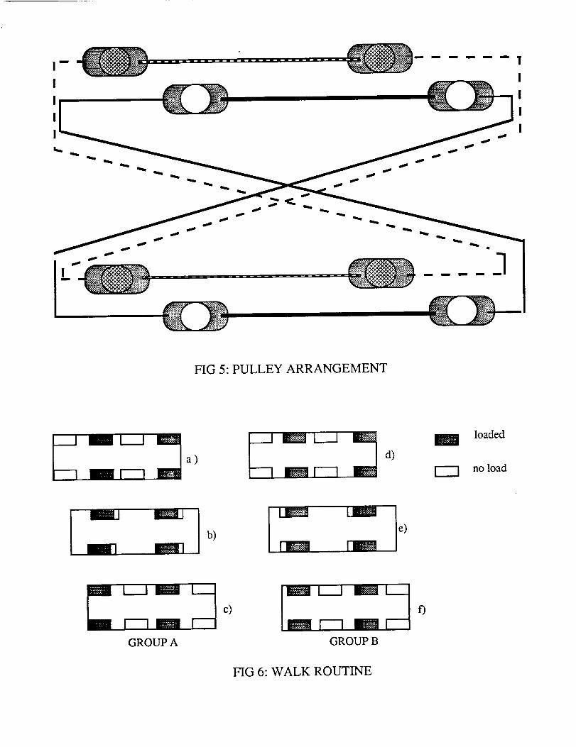
FIG 5: PULLEY ARRANGEMENT
a)
,!!U.'_'_:!!:!:
d)
loaded
no load
P
b)e)
Z I_..Am _c)[1 m
GROUP A GROUP B
f)
FIG 6: WALK ROUTINE
WORM GEAR
MOTOR
BALL SCREW
LINEAR BEARING
FIG 7: LEG ASSEMBLY
HG 8' SENSOR LOCA_ON
OFF OFF ON IPULSE WIDTH _ PULSE WIDTH --_
V Max.
V Zero
PROPORTIONAL VOLTAGE = [1- (time off/time on) ] x V Max
Fig. 9: PWM Waveform
HI
LOW
0 180 360
HI
LOW
0 180 360
y = H x (1 - x/l)^2 H = max height Velocity= 0 @ x = 11 = decay stride length
Fig. 10: Leg Height versus Angular Position of Crank Arm

APPENDIX A:
CHASSIS & BIGFOOT

DESIGN AND CONSTRUCTION OF THE
CHASSIS AND BIGFOOT
Tom Nave
Lisa Steen
Darren Leep
Tim Condon
5-7-90
INTRODUCTION
The duties of the spring semester of the walking robot
class were to construct, based on designs from the students
in the fall semester, the walking machine Proto Terp IV for
competition in the 1990 Society of Automotive Engineers (SAE)
Walking Robotic Machine Decathlon. All facets of construction
were based on the feasibility of the design, availability of
materials, and time constraints.
The responsibility of the chassis and bigfoot group were
to review the fall semester design, propose modifications
(which were needed, see design evolution section), and
construct the article. These tasks were accomplished in the
set time period of ii weeks. This doesn't mean that it was a
smooth transition from design proposal to construction. There
were many instances where alternative design proposals had to
be incorporated well into the construction stage. This was
basically for strength-to-weight optimization of the chassis
towards the end of the construction stage.
The fabrication of the chassis and application of a
previous "bigfoot" involved many hours of design
consideration, procurement of materials, and machine shop
labor to come into fruition. The result was a significant
contribution to the waking robotic machine Proto Terp IV as a
foundation for driveline, legs, and computer hardware.
Desiqn Evolution
Starting with the design proposed by the Fall 1989
semester of the walking robot class, the Chassis and Bigfoot
group of Spring of 1990 made several design modifications to
improve the functionality and expedite the construction of
Proto Terp IV. The Fall 1989 design proposal also included
the drive mechanism, which was not assigned to the Chassis
and Bigfoot group of Spring of 1990. Therefore, modifications
included in this report do not refer to drive mechanisms
(except Bigfoot), which were assigned to a different group.
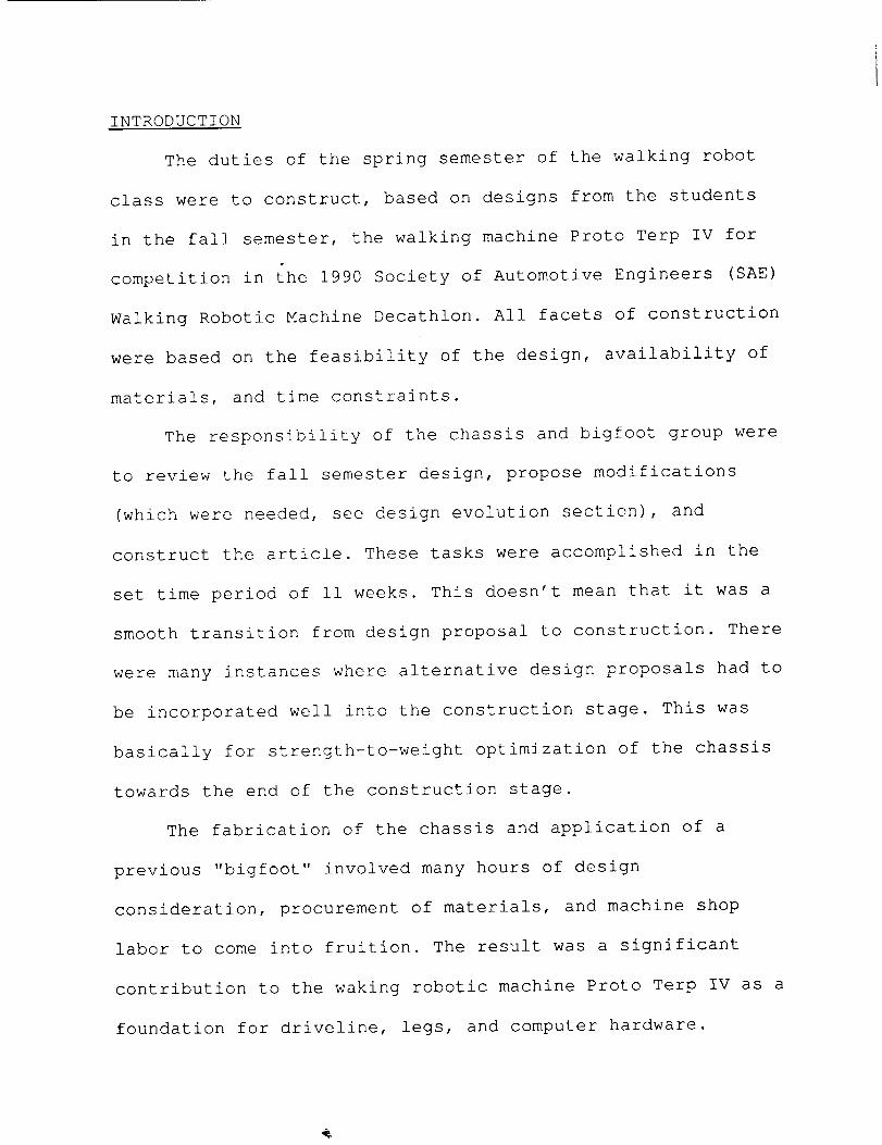
From the first proposed design of the chassis (Fall of
1989), the design team and advisors believed that the
aluminum blocks used to hold the rods to the chassis were too
heavy and that the rods could be held in place by plates
fastened to extended aluminum tubing (see fig. I) . This
design revision used all the same dimensions and was
essentially a materials revision. From here the chassis was
revised three more times. Design revision 2 was the same
basic idea as revision I, but due to materials available from
the physics shop at that time (2"x3" channel as opposed to
1.5"x2") the design was modified to accommodate the
availability of these materials. However, due to further
investigation as to why the dimensions of the chassis were
chosen, which was for SAE Walking Robotic Machine event
LLo
r_
._._.J i
Z020j I,IO_ 0"_
\
_;_JZ_W
_ _o
i°-°i_
o-
\
\
\
® ®
W
<._J13..
Z
_.1
" \,e
"\
E°_
E
E
0
"13
e-
u')
"1
Ii
three, foot placement, the design was revised a third time.
The event states:
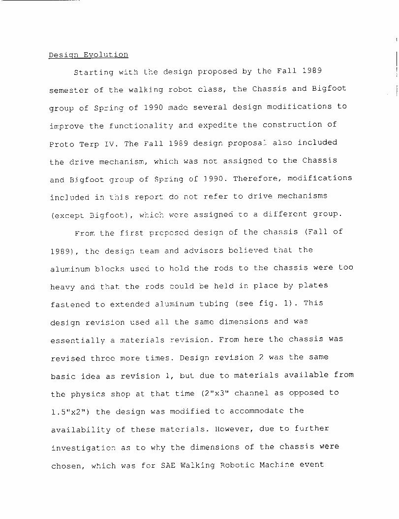
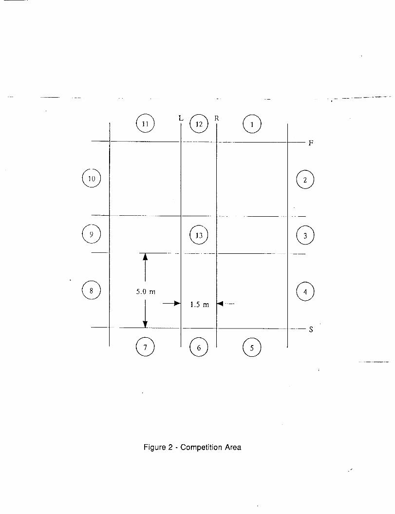
"Starting at Area 6, the Walking Machine must walk
across the contest area and cross line F. No foot of the
Walking Machine may at any time completely cross _line L or
line R. Four stripes, each 20 cm wide and parallel to lines S
and F, will be placed completely across the walking path. The
second stripe will be placed 1 meter after the first stripe,
the third 0.5 meters after the second, and the last stripe
1.5 meters after the third. The Walking Machine must step
over the stripes and not touch any of the four stripes with
any of its feet (see fig. 2, stripes not shown)."
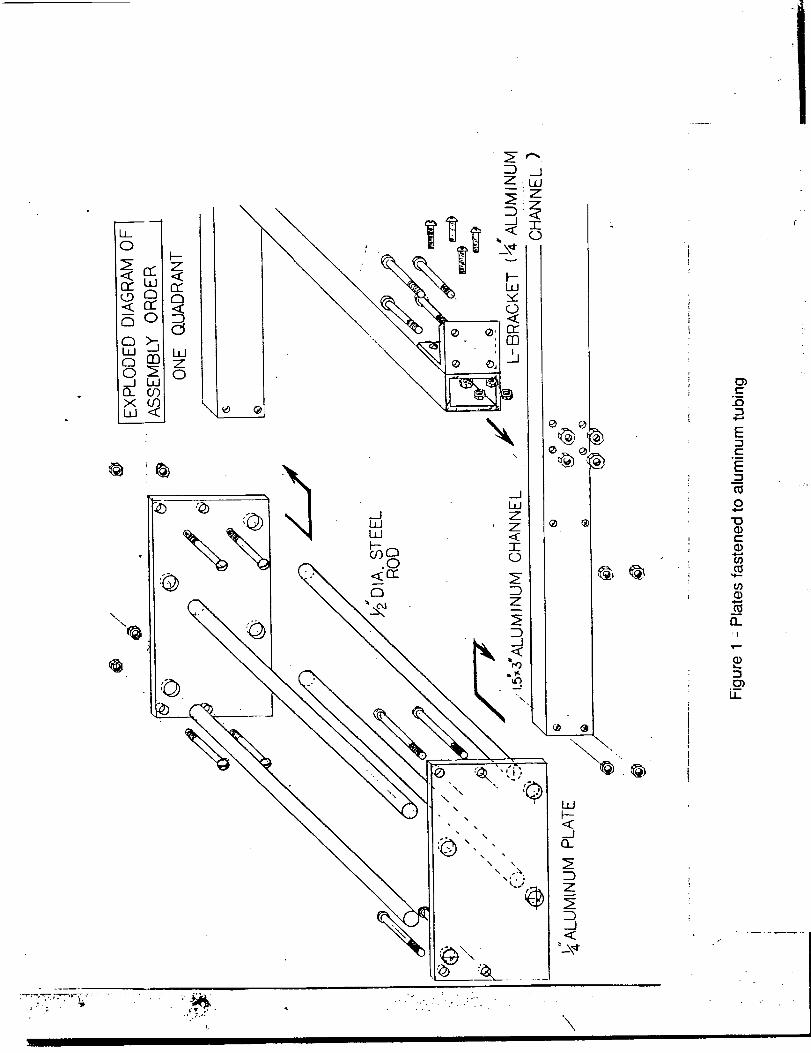
The original distance, proposed by the Fall of 1989,
between the legs of 21.75 inches would not allow clearance of
the first stripe by the second set of legs on the second
stride. The minimum distance required between the legs is
27.5 inches to have the legs clear the first stripe (see fig.
3). The distance between the legs could have also been less
than 19.5 inches, but that would have caused stability
problems and altered the stride length, which had to remain
fixed at 30 cm. So the overall dimensions had to be changed
to accommodate this latest revision. The chassis was
lengthened to 49.75" and this in turn dictated that the rod
lengths would need to be lengthen to 21.875" This
© L
©
T5.0rn
1.5 m
F
©
Figure 2 - Competition Area
t
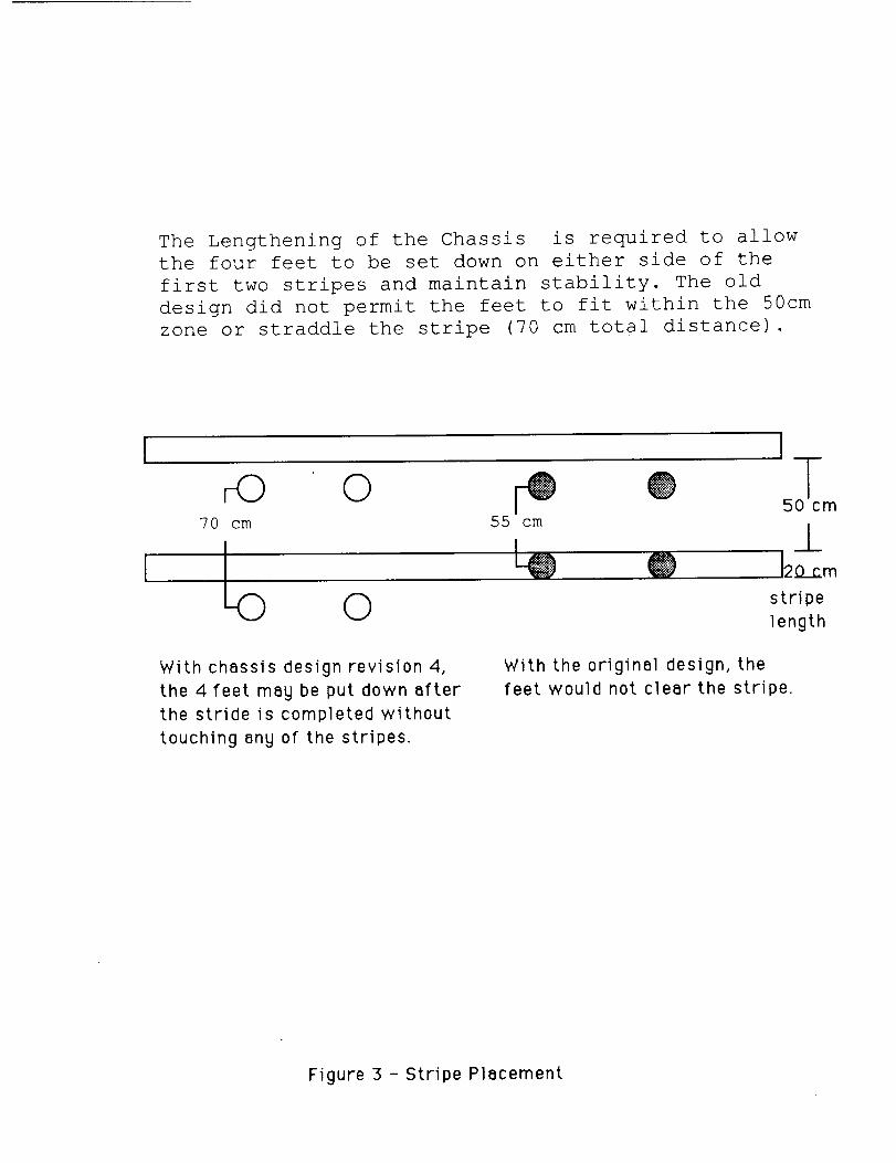
The Lengthening of the Chassis is required to allow
the four feet to be set down on either side of the
first two stripes and maintain stability. The old
design did not permit the feet to fit within the 50cm
zone or straddle the stripe (70 cm total distance).
IT_o o _ e _o:_70 cm 55 cm
O stripelength
With chassis design revision 4,
the 4feet may be put down after
the stride is completed without
touching any of the stripes.
With the original design, the
feet would not clear the stripe.
Figure 3 - Stripe Placement
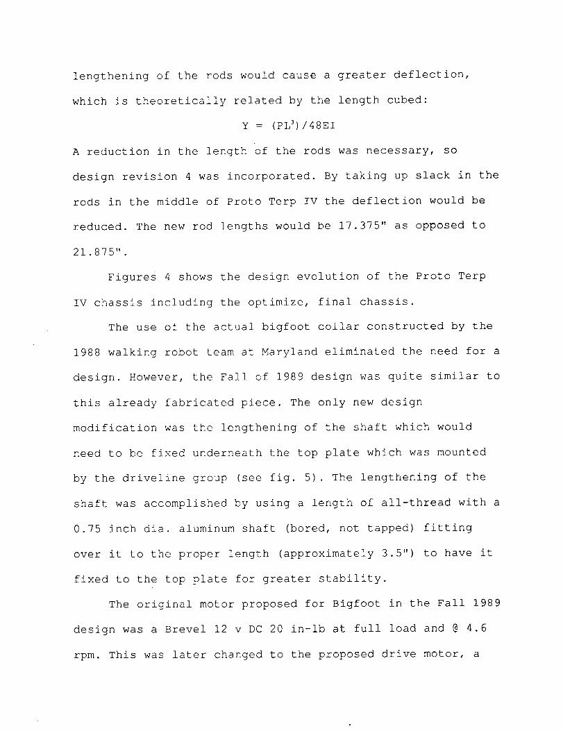
lengthening of the rods would cause a greater deflection,
which is theoretically related by the length cubed:
y : (pL3)/48EI
A reduction in the length of the rods was necessary, so
design revision 4 was incorporated. By taking up slack in the
rods in the middle of Proto Terp IV the deflection would be
reduced. The new rod lengths would be 17.375" as opposed to
21.875".
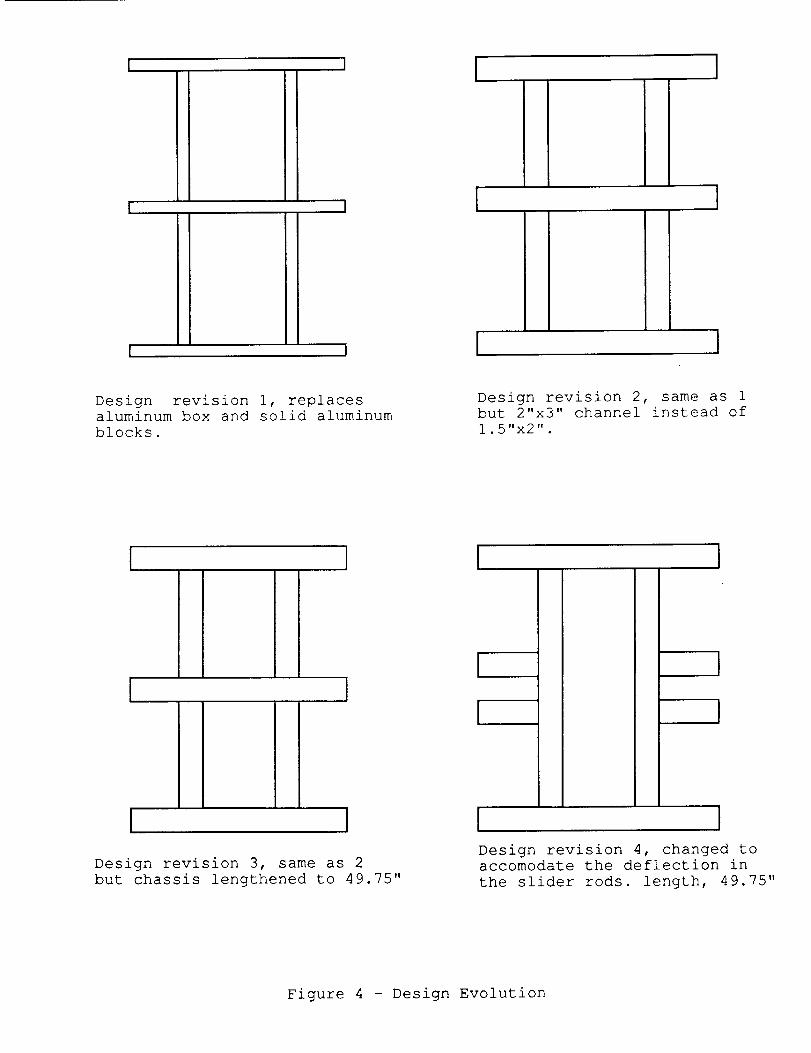
Figures 4 shows the design evolution of the Proto Terp
IV chassis including the optimize, final chassis.
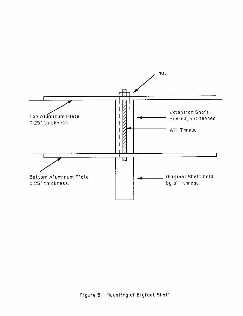
The use of the actual bigfoot collar constructed by the
1988 walking robot team at Maryland eliminated the need for a
design. However, the Fall of 1989 design was quite similar to
this already fabricated piece. The only new design
modification was the lengthening of the shaft which would
need to be fixed underneath the top plate which was mounted
by the driveline group (see fig. 5). The lengthening of the
shaft was accomplished by using a length of all-thread with a
0.75 inch dia. aluminum shaft (bored, not tapped) fitting
over it to the proper length (approximately 3.5") to have it
fixed to the top plate for greater stability.
The original motor proposed for Bigfoot in the Fall 1989
design was a Brevel 12 v DC 20 in-lb at full load and @ 4.6
rpm. This was later changed to the proposed drive motor, a
I I I I
I I
I I
ittI
I I
+
I
I I
Design revision i, replacesaluminum box and solid aluminum
blocks.
Design revision 2, same as 1but 2"x3" channel instead of
1.5"x2".
I
I
ti
IiI
[ I
I I [ ]
Design revision 3, same as 2
but chassis lengthened to 49.75"
Design revision 4, changed to
accomodate the deflection in
the slider rods. length, 49.75"
Figure 4 - Design Evolution
fTop Aluminum Plate
0.25" thickness.
Bottom Aluminum Plate
0.25" thickness.
I I
I I
I I
I I
I 3"
I I
I I
I I
U
nut.
I
Extension Shaft
Boared, not tapped.
All-Thread
Original Shaft held
by all-thread.
Figure 5 - Mounting of Bigfoot Shaft
Von Weise 12 v DC 8 in-lb @ 200 rpm and full load. This
motor had a 14:1 gear reduction, and would operate unloaded
at 108 rpm. Project advisors recommended that the Bigfoot
motor should obtain a e of 30 rpm in 90 ° of polar
displacement. An angular acceleration of 0.047 rad/sec 2 was
calculated from an estimated mass moment of inertia (see
calculations in Appendix). The calculations reinforced
theoretically that the Von Weise motor would be sufficient,
but an experimental test rig was constructed to verify this
information. With a much smaller mass moment of inertia
simulated by free weights placed at various distances from
the centroidal axis, motor operation with the Von Wiese not
only showed very high start-up current draw (sometimes 14
amps), but also enough wear on the plastic gear reduction to
render the motor inoperable. After attempts to reduce the
opposite end of the Von Wiese were considered, another motor
was ultimately chosen for the Bigfoot motor, with selection
made by the driveline group.
The same gear reduction that was used on the 1988 Bigfoot was
used on the 1990 Proto Terp IV.
The final design was design revision 4 with
modifications to save weight and reduce the overall width by
2.25" Additional plates mounted by the driveline group gave
the chassis further stability.
Construction of Chassis
The chassis for the 1990 walking robot was mostly
constructed of 2"x3"x.125" aluminum channel. The frame, or
channel portion, of the chassis was constructed first. We
cut the channel sections on the Do-All saw and machined them
to the exact length using the milling machine. Next, we cut
the angle brackets for the corners using the Do-All and, for
safety, we deburred the edges by hand. Angle brackets were
used for the corners for two reasons. First, the angle
brackets provided the strength and stability needed to hold
the joints together. Second, they simplified construction by
guaranteeing perfectly square connections (see Fig. I) .
The angle brackets were attached to the channel sections
by drilling the holes through both pieces at the same time on
the drill press. This turned out to be quite a job, since
the angle bracket hit the drill chuck, and the drilling
procedure turned into a complex process of clamping,
drilling, disassembling, drilling, and reassembling, etc.
The pieces of the frame were custom fit to a specific
location, even though they could be interchanged. Once the
frame was assembled, we carefully and explicitly identified
the location and orientation of each piece, so that when the
frame had to be taken apart, it could easily be reassembled.
The next part of the chassis to be constructed was the
slider-rod assembly. The slider rod assembly was the most
critical part of the chassis. The rods had to be perfectly
parallel, or the linear bearings of the legs would not work
smoothly. In addition, the rods had to be perfectly aligned
so that the robot would walk in a strait line.
The first step of the construction of the slider-rod
assembly consisted of cutting-out all the plates using the
band saw. Once the plates were cut out, we used the milling
machine to cut them all to exactly the same size. We used a
fly-cutter bit to cut all of the pieces at the same time.
Once the plates were cut out, we pinned them together and
drilled them in pairs, so that the rods would be exactly
parallel. The holes for the rods were drilled using the
milling machine for exacting precision.
Once the holes for the slider-rods were drilled, the
plates were mounted on the frame, and the rod lengths were
measured and cut. The rods were custom fit to their exact
location. This was necessary so that they would not slip out
once they were installed. The upper rods were held in place
by the channel, and the lower rods were held in place by
snap-rings. The grooves for the snap-rings were cut right at
the inside edges of the plates, so that the rods would not
slip out.
The slider-rods proved to be difficult parts to obtain.
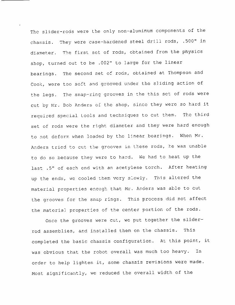
The slider-rods were the only non-aluminum components of the
chassis. They were case-hardened steel drill rods, .500" in
diameter. The first set of rods, obtained from the physics
shop, turned out to be .002" to large for the linear
bearings. The second set of rods, obtained at Thompson and
Cook, were too soft and grooved under the sliding action of
the legs. The snap-ring grooves in the this set of rods were
cut by Mr. Bob Anders of the shop, since they were so hard it
required special tools and techniques to cut them. The third
set of rods were the right diameter and they were hard enough
to not deform when loaded by the linear bearings. When Mr.
Anders tried to cut the grooves in these rods, he was unable
to do so because they were to hard. We had to heat up the
last .5" of each end with an acetylene torch. After heating
up the ends, we cooled them very slowly. This altered the
material properties enough that Mr. Anders was able to cut
the grooves for the snap rings. This process did not affect
the material properties of the center portion of the rods.
Once the grooves were cut, we put together the slider-
rod assemblies, and installed them on the chassis. This
completed the basic chassis configuration. At this point, it
was obvious that the robot overall was much too heavy. In
order to help lighten it, some chassis revisions were made.
Most significantly, we reduced the overall width of the
robot. Next we cut the plates and the ends of the frame
along the angle formed by the slider-rods (see Fig. 6). This
also greatly improved the cosmetic appearance of the robot.
We obtained weight savings of approximately i0 ibs. by taking
these steps.
The final part of our assignment was to construct a
secure, protective, stable crate to use to transport the
robot. The crate was constructed out of donated 2"x4" lumber
and was custom fitted to exactly fit the robot. The crate
protects the robot from low impact on all sides and holds the
robot of the ground approximately I".
Conclusion
In conclusion, the chassis of the 1990 University of
Maryland Walking robot, Proto Terp IV, was the end result of
many design revisions, changes due to construction
difficulties and constraints, material demands, and weight
requirements. The main thrust of the chassis was to provide
a geometrically exact, structurally sound, stable, light
weight base upon which to mount all of the other components
of the robot. We succeeded in obtaining these goals and
providing such a platform upon which to assemble the robot.

APPENDIX B:
DRIVELINE
ENME 408
Prototerp IV Walking RobotDriveline Group Report
May 7, 1990
Faculty Advisors:Dr. AzarmDr. Tsai
Mark Uebel, TA
Group Members:
Phil Grotheer (Group Leader)Morad Hekmat
Dave RussellHossein Tavakoli
Gary Young
Table of Contents
I. Introduction ................................. 1
Overview ............................... 1
Driveline Group Responsibilities ................. 2
II. Design Considerations .......................... 3
III. Theory and Design ............................ 5
Gearbox ............................... 5
Outer Drivetrain (Crank End) .................... 5
Connecting Rods and Cables ................... 6
Crank and Slider Mechanism ................... 7
IV. Manufacturing .............................. 10
V. Recommendations for Mars Exploration ............. 12
VI. Conclusions ............................... 14
VII. Appendix ............................... 15
A. Figures .............................. 15
B. Calculations ............................ 26
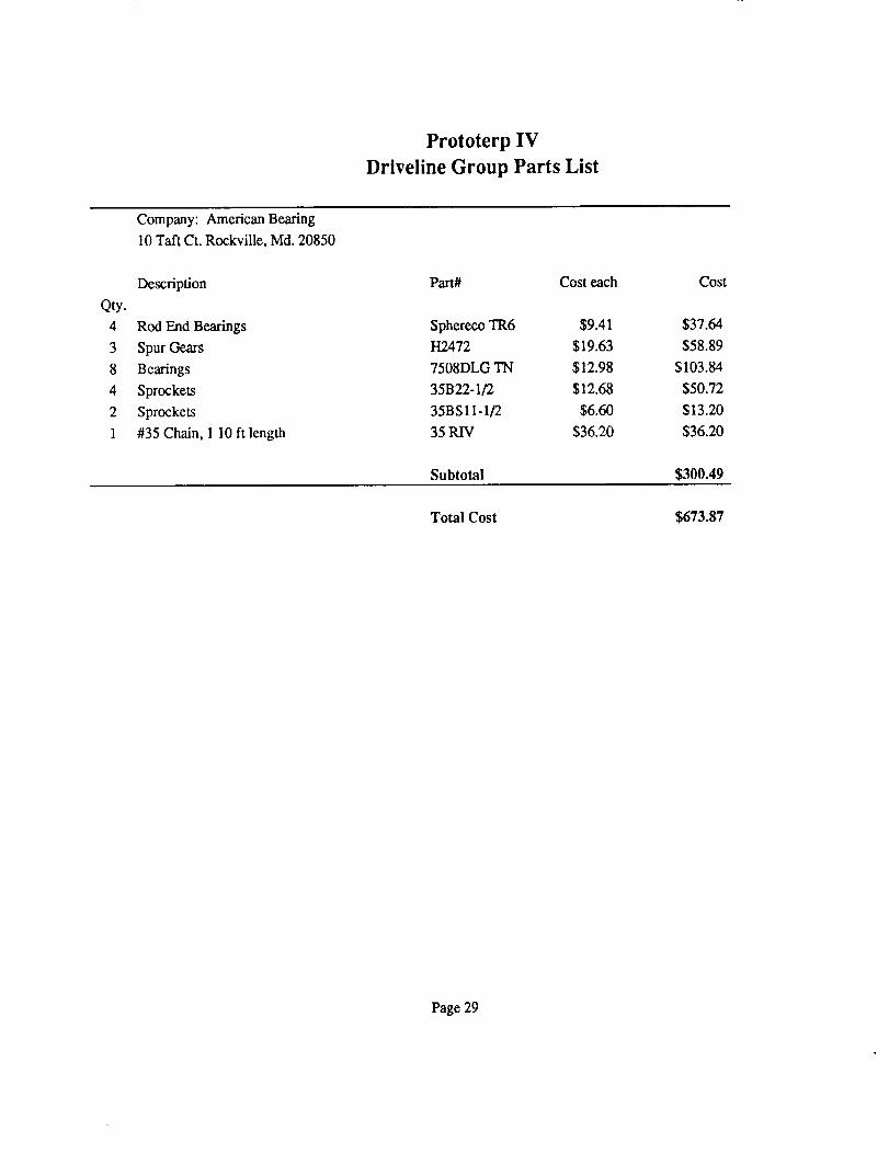
C. Parts list .............................. 28
D. Timeline .............................. 30
E.
VIII. References and Acknowledgements ................
Specifications for Tribolube 15 ................. 31
34
ENME 408
Prototerp IV Walking RobotDriveline Group Report
Introduction
Overview
Prototerp IV is a walking machine designed and built by University of Maryland studentsin the class ENME 408. The University of Maryland began offering ENME 408 four
years ago for the purpose of allowing students in mechanical and electrical engineering to
work together in a team environment to study state-of-the-art robotics, and to design and
build a functional walking machine.
Each year, a machine has been entered into a decathlon sponsored by the Society of
Automotive Engineers. The decathlon is a nationwide collegiate competition with 10
events designed to exploit the abilities of the walking machines.
Prototerp IV was designed largely with the rules of the competition in mind. However, the
intent of the rules was used as a guideline, rather than the actual rules themselves.
Therefore, our robot was designed to conform to many applications, not just the decathlon.
The following goals were set for the design of the machine:
1) The machine should be able to walk straight quickly. Walking is defined as a
mobile machine supported discontinuously and propelled by articulated
mechanisms (the legs). Each leg must have one or more joints or hinges by
which it moves relative to all legs or the frame. A leg may pivot, slip or slide
on the supporting surface during walking motion, but it may not roll.
2) The machine should be able to turn quickly.
4) The machine should be able to walk with a variable stride length.
5) The machine should be able to walk over a small staircase (with a minimum
size defined by the decathlon rules).
6) The machine should be able to push a hockey puck with a stick attachment.
7) The machine should be able to "see" by sensing retroreflective material.
8) The machine must be able to be programmed to do any of the above functions
autonomously, and in combination.
The last requirement is very important, because it allows our machine to be called a
"robot". Part of the RIAA definition of a robot is "a reprogrammable,multifunctionalmanipulator". Our machinefits this definition, in that it can manipulatea hockey puck (orany object placedon it) in any way definedby the softwareprogramming.
The project was split over two semesters. The first semesterstudentsdesignedthe roboton paper and submitted a design report. The second semester students made initialmodifications to the designand built the robot, with minor changesalong the way.
The design and manufacturing of the robot was divided into five groups: (1) Leg andhockey, (2) Chassis and Bigfoot, (3) Driveline, (4) Control-Software, and (5) ControlHardware. This report details the work done by Driveline group, from original designthrough the entire manufacturingprocess.
Driveline Group Responsibilities
The robot was designed with 8 legs which slide horizontally relative to the chassis. At
any moment during walking, four legs rest on the ground, driving the chassis forward,while the other four legs are returning to the front of the robot. The legs were all linked
mechanically, so that they do not slide independently in the x-direction (horizontally).However, each of the legs can extend in length, allowing the robot separate x- and y-
degrees of freedom. The driveline team was responsible for all of the parts propelling therobot in the horizontal direction. This included a gearmotor and gearing mounted in a
gearbox, chains and sprockets necessary to transfer the motor power, an offset crankmechanism used to convert the rotational motion to translational motion, and the physical
connection between legs including wire, pulleys and tubing.
2
Design Considerations
Many factors were accounted for in the driveline design. These factors were governed by
the following:
1) Goals of the overall robot design
2) Power requirements
3) Simplicity of design
4) Weight considerations
5) Stress considerations
6) Ease of manufacture
7) Ease of maintenance
8) Esoterics
Past University of Maryland robots and other universities' robots were studied to optimize
the design, and a great deal of forethought preceded the final design. The following is a
summary of the design steps taken to adhere to the above guidelines:
The robot was based on an x- y- degree of freedom system. The separation of the x-
direction motion from the y-direction motion provided flexibility of motion, while
simplifying the driveline. The horizontal drive mechanism is simplified by the fact that it
need not supply power to support the weight of the robot. The only work done by thedriveline is to accelerate the robot in the horizontal direction. This allows for a high speed
robot with relatively little driveline power.
The driveline was driven by one motor. This allows a simple control scheme, but does
not interfere with any of the requirements of the robot. The variable stride requirement is
taken care of by leg motors unrelated to the driveline. Using one motor prevents timing
problems prevalent in multiple motor systems, and made manufacture and maintenance
easier.
A quick-return slide mechanism was used. The driveline was designed with a linkagewhich returned the legs to the driving position faster than it drove the legs moving the
robot. This improves the uniformity of the robot's velocity. The quick return allows the
legs on the return stroke to start moving in the direction of the drive stroke before they
touch the ground. In other words, there is a slight overlap of strides, much in the way ahuman walks.
The drive motor runs continuously in one direction during walking. By using the
crank-slider mechanism, the drive motor need not reverse to drive the legs back and forth.
This makes for a faster robot, since the motor need not overcome the inertia developed
once it has started moving. It also prevents alternating stresses in shafting and other
mechanical parts. This allowed for sizing components smaller, thereby reducing weight.
Frictional losses were minimized. This was accomplished in part by designing the
gearbox with spur gears as opposed to bevel gears. This has the added benefit of allowinglooser tolerances in manufacturing the gearbox. Pulley angles were kept large, high-quality
bearingsand pulleys were used, and using hardenedsteel rods were used for the legs toslide on. In addition, the angle of the offset crank mechanismwas minimized to preventexcessivefriction (seeTheory and Design section).
The drive motor and main gearing were assembled in a gearbox. This modular design
allowed for the driveline to be assembled and tested separately from the chassis. Thismakes manufacture and maintenance easier. It also allowed for flexibility of placement of
the driveline on the chassis, which was necessary since other components' designs were notsolidified until several weeks into manufacture.
Chains were used to link the gearbox to the chassis-mounted drive components. This
avoided having to tolerance the gearbox mounting precisely; slots were machined to allow
for removing slack in the chains during gearbox mounting.
4
Theory and Design:
As mentioned before, Prototerp IV implements the use of a single drive motor to translate
rotational motion to the translational motion of the eight sliding legs. It has been decidedearlier that a crank-slider mechanism would be the means for the transformation of these
motions. It is still necessary however, for the primary drive of a main motor to be
translated outwards to two vertically mounted shafts in a predetermined location such that
their direction of spin is opposing one another.
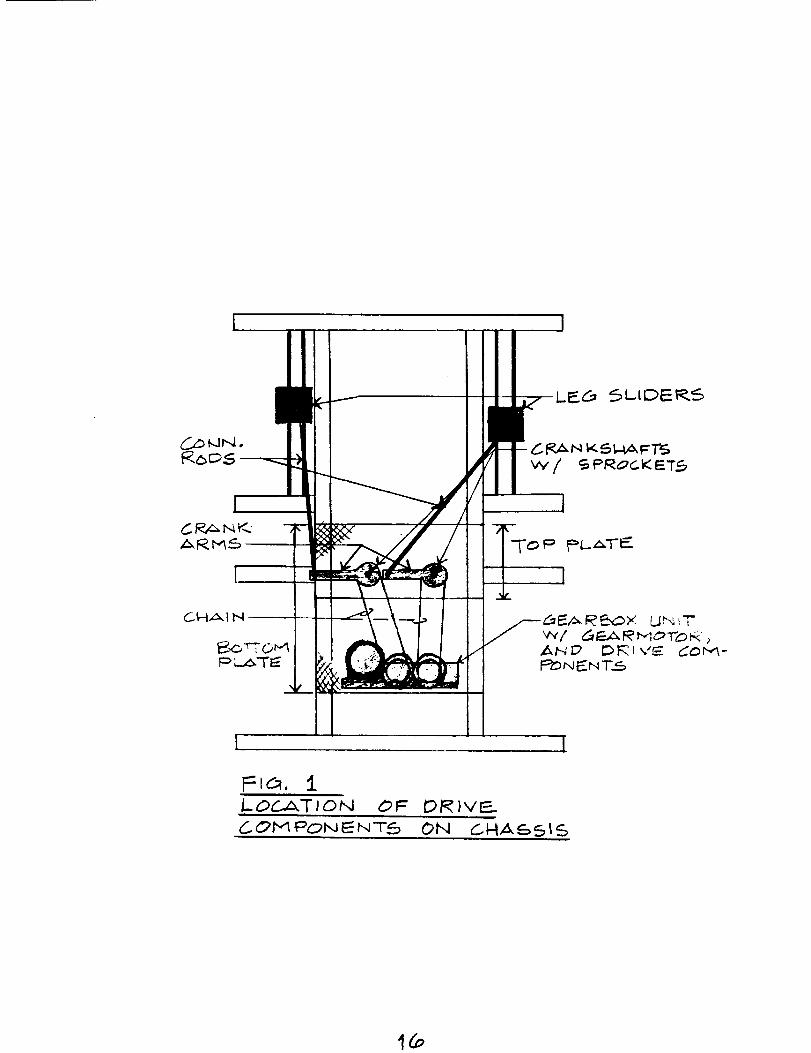
A separate gearbox has been built which has within itself two adjacent shafts where
sprockets have been mounted to drive a dual chain system outwards to the two outer
"crank-shafts". The gearbox works such that the spins of the two internal shafts are
opposing. This creates identical spins at the cranks. On top of the crank shafts aremounted crank arms which are the circular motions of the crank slider model. The
connecting rods attach to the ends of the crank arms and follow out the leg slider blocks.
This completes the description of the drive mechanisms which propel two opposing legs on
either side of the robot (fig.l).
Gearbox
The gearbox was built totally separate from the robot, was installed after construction of
the chassis, and remains an adjustable, removable component of the robot. It is
constructed from a large C-channel which houses the motor and all internal driveshafts.
The initial design consisted of a horizontally mounted gearmotor which sat on top of the
channel. The horizontal motor coupled up with a shaft with a bevel gear translating to a
vertical shaft. The vertical shaft drove an adjacent shaft, producing again the opposing
spin (fig.2). One problem in the use of bevel gears are their difficulty alignment during
assembly. It was decided that a simpler approach would be to use spur gears in the
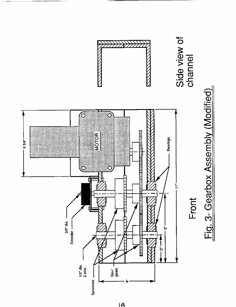
meshing of the drive motor and the first shaft. The final design was a slight modification
to the earlier concept in that the drive motor was mounted vertically in the aluminum
channel housing with its drive shaft parallel and adjacent to the first shaft (fig.3). With
this setup, the strict use of identically sized spur gears allowed for a much more forgiving
design in the construction aspect. The bearings used in the gearbox came with snaprings
installed in the outer race which allowed for a sandwich type fit when an entire shaft is
installed in the housing. On the two vertically mounted shafts sprockets were installedwhich drive the two sets of chains to the outer cranks.
The advantage in having a totally separate gearbox on the robot is that it can be adjusted
backwards and forwards in its mountings to create ample chain tension. In other words,
the gearbox was mounted with bolts to a bottom plate which had slots machined in it.
This was a very simple method for creating and maintaining a certain tension in a chain
drive system that cannot allow for any looseness in the final walk of the robot.
Outer Drivetrain (Crank End)
One advantage in a chain drive system is the option to change the reduction in the drive at
any stage in the robot. The chain drive built used identically sized sprockets throughout
which gave the sameangular velocity of the final cranks with respect to the drive motor.Through the operationof the robot, it was unnecessaryto changethis drive reduction sincethe torques required of the system were sufficiently met with the capability of the drivemotor. If the need were there to change,different sized sprocketsat the gearbox weresuppliedto allow for a 1/2 reductionoverall from the gearboxto the crank arms.
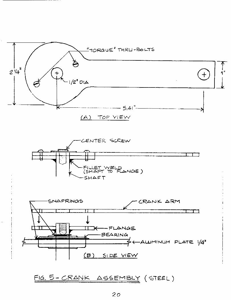
The previousdesign of the crank assemblywas to have steel shafts with aluminum crankarms (fig.4). Since it is impossible to weld or bond two dissimilar metals, it would benecessaryto bolt one to the other. One change that was made to this is to makeeverythingout of steel including the crank arm. In this case, it was possibleto weld thesteel shaft to a steel flange, which was bolted to the steel crank arm. The reasonfor theseparateplates is so the crank arm can be adjusted with respect to the crank shaft toobtain very small angular incrementswhich will give a fine tune adjustmentof one set oflegs with respectto the other. Every time a small angular adjustmentis made a separateset of holes were drilled through the arm and the flange, then they were through-boltedwhen the proper settingwas gained. The bearingsused for the crankshaftswere the sameas for the gearboxbecausethe samestressesarepresentin all four shafts. The connectingrods were attachedto the endsof the crank arms(fig.5).
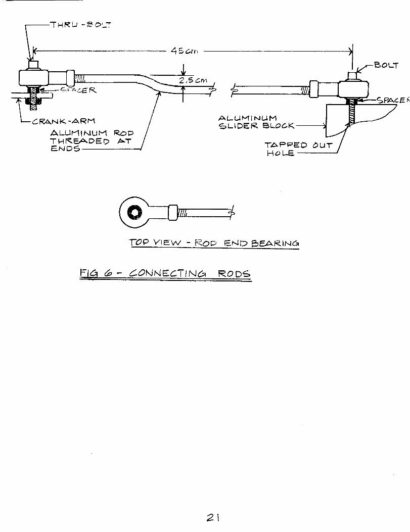
Connecting Rods and Cables
The purpose of the connecting rods are to translate pure compressive and tensile forcesfrom the rotation of the end of the crank arm to the translation of the leg sliders. A very
simple design for this is to use rod end bearings, which connect to the end of a rod andattach to a fixed post while allowing for angular deformations. This uses a ball and socket
type device. For a connection of the rod end bearing to the rod, the rod needed to bethreaded. 3/8 inch aluminum rod was very lightweight and useful for this application.
One modification that was made to the connecting rods was that the height difference
between the top of the crank arms and the top surface of the leg slider block had to be
accounted for by creating a bend (fig.6).
The drive system described to this point includes whatever necessary to propel two
opposing legs. The robot has however, eight legs. For this reason, the motion of eachdirectly driven leg must be mimicked by the other three legs which will create two sets of
four legs. To connect all sets of legs which are in front and back of each other, solid
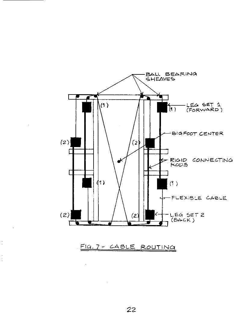
connecting rods were used to pair them up. A cable system was used to move the set of
legs on the opposite side of the robot than the directly driven side (fig.7). In order toroute the cables throughout the robot, small pulleys were used. Friction was cut to a
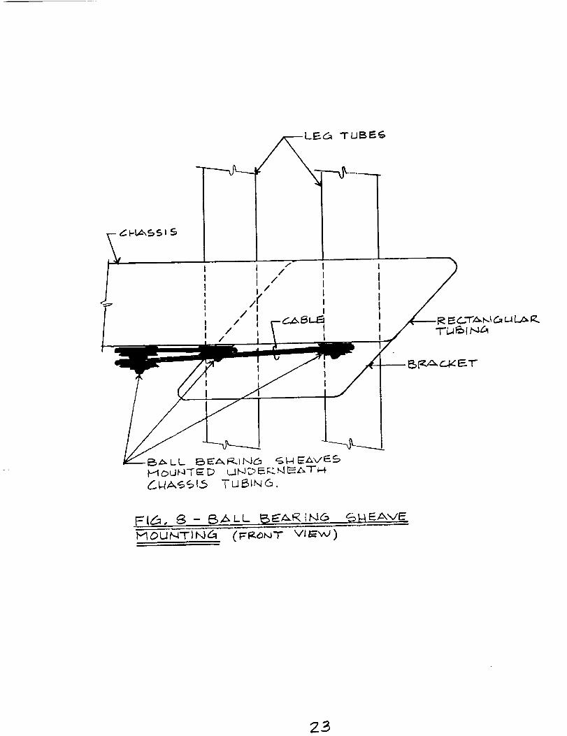
minimum by using ball bearing sheaves. A previous design was to mount the sheaves inthe cross section of the chassis tubing by putting shafts inside. A modification to this was
to place the sheaves on the underneath surface of the tubing (fig.8).
The routing of the cables throughout the robot must be done so as not to obstruct any of
the other moving components. Fortunately, by placing the entire cable setup underneath
the chassis, the only thing it must pass by is the shaft for the bigfoot mounting. This was
a very simple problem to overcome by the placement of the rear two sheaves further
inward. By doing this, the intersection of the two sets of cables is behind the bigfoot
shaft. The connectionsand tensioningof the cables was made possible by using mini-turnbucklesand cable clamps. Although being very small and detailed components,theyproved to be absolutelynecessaryin the use of a mini cable systemand fine adjustmentofall legs could not have beenmadewithout their use.
Crank and Slider Mechanism
It has been determined to this point that a combination of a gearbox and its' connectedchain drive would be most advantageous for this particular Robot design. The task at this
point is to size all of the interrelated components for the best overall weight and
performance. To be able to do this however, the amount of power being transmittedthrough the drivetrain must be calculated. For this reason, the final crank arm torque and
RPM must be specified such that the Robot will have the desired stride and velocity that
will be competitive.
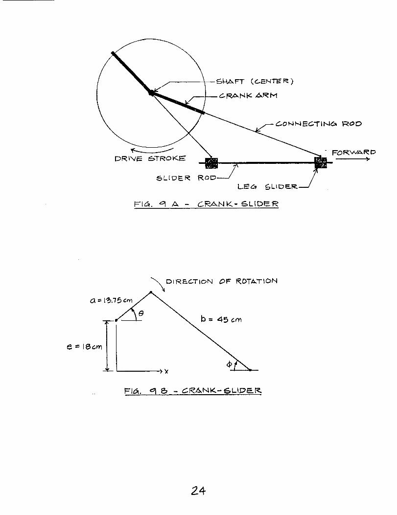
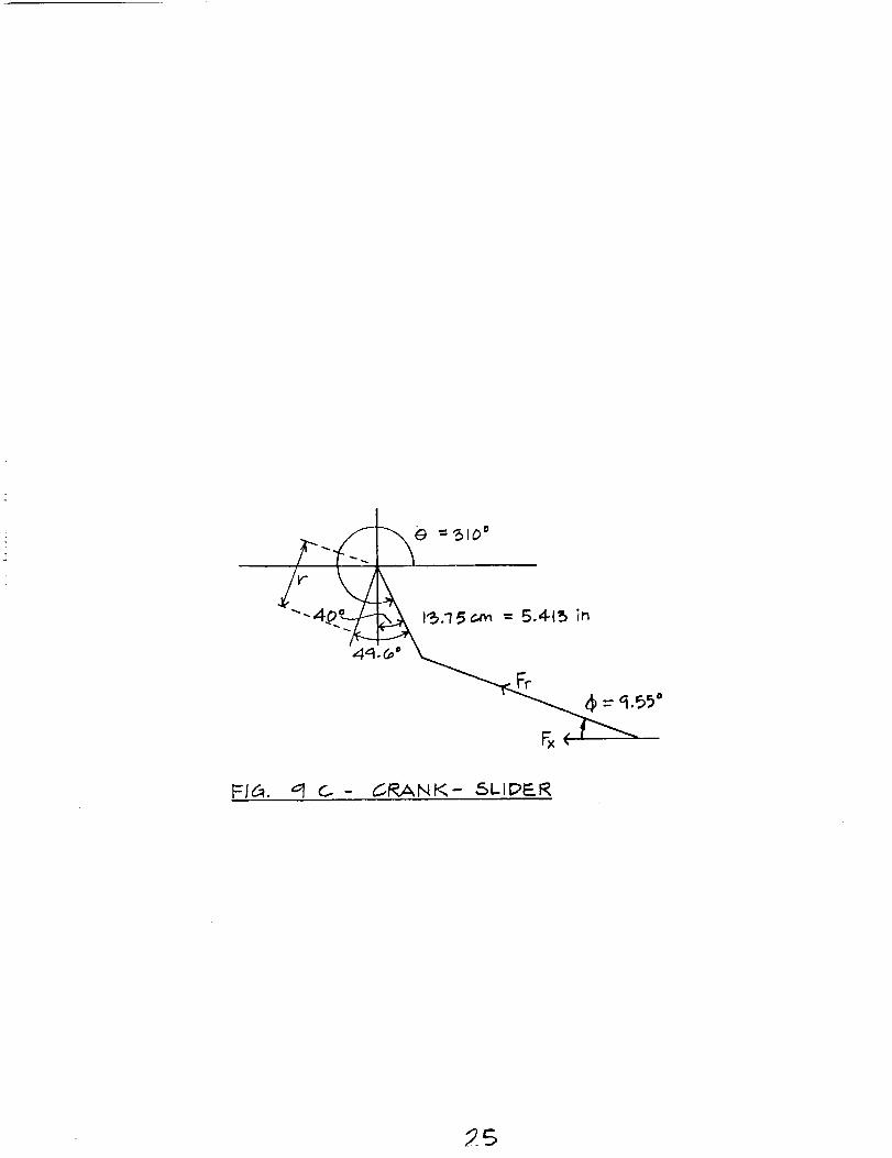
The geometry of the crank and slider was chosen to give a walking stride of approximately
30 cm (fig.9). The offset was chosen arbitrarily so that there would be enough quick
return action to give an observable advantage in uniform velocity but not so much thatthere would be tremendous frictional forces in the slider mechanism when large angles in
the connecting rod with respect to the slider rod are produced.
By examining that if a full revolution of the crank takes place, two full strides will occurbecause each half turn of a crank arm is propelling a set of legs which drives the Robot
forwards. This holds true if a desired Robot velocity is 30 cm/sec and a half a revolution
per second is required. The approximation for a 30 cm stride is probably very accuratebecause the actual horizontal travel of the sliding legs from fig.9 is 30.37 cm and the feet
will not be placed on the ground exactly at the ends of the travel but rather a little further
in from the ends.
The task is to now determine the maximum torque required at the crank arm to propel the
Robot at a velocity of 30 cm/sec and at a crank angular velocity of 30 RPM. The major
reasoning in determining the torque at the crank will be due to the acceleration anddeceleration of the entire Robot because of the non-uniform velocity of the crank-slider
throughout a revolution; hence, a plot will be needed of torque with respect to all othervariables including the angles associated with the geometry of the crank-slider. To do this,
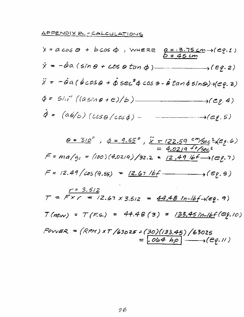
some equation will be needed to explain the kinematic motion of the crank-slider. From
fig.9b, the position equation of the slider with respect to angles theta and phi can be
calculated (eq.1). When time is introduced into this equation, then differentiated, a velocity
profile is obtained as (eq.2). When differentiated again, the linear acceleration is obtained
(eq.3). The angle between the horizontal and the connecting rod can be found (eq.4).When differentiated, its' angular velocity can be found (eq.5). A previous groups task was
to make a plot of the torque, linear velocity and acceleration with respect to the angles
involved using a Lotus Program Spread Sheet to find the point throughout a revolution at
which the maximum torque occurs. When this was performed, the point of maximum
torque corresponded to values of (eq.6). This value for maximum torque however, does
not correspond to the value for maximum acceleration. The reason for this is thecharacteristic of a mechanical crank. In other words, the point of maximum acceleration is
at the endpoint of its' motion, and this also happensto be at the point of the crank'smaximum mechanical advantage. So there is no torque on the crank arm at thisinstantaneousmoment. So the point of the maximum torque will be at someshort momentof time after it has reachedits' maximum horizontal extension,which is exactly what thismathematicalmodel has shown.
The torque can be directly calculated as follows: A mass must be approximated for the
robot and the torque accounted for will be accelerating this mass. Using this assumption,Newton's law can be used to find the horizontal force exerted on the legs (eq.7). At an
angle of 9.55 degrees from the horizontal, the force in the connecting rod can be calculated
(eq.8). From fig.9c, the acting radius of the torque can be calculated and then the torque
(eq.9). With a factor of safety of 3 to account for frictional forces, additional forcescreated in returning legs, or any miscalculation in assuming a robot mass, a safe calculation
for the torque can be determined which corresponds to an angular velocity of 30 rpm
(eq.10). Now that the torque and RPM requirements of the crank arm are determined, asuitable drive motor can be chosen according to the power requirement. The power
required for the motor with
a sizable factor of safety can be found (eq.ll).
All components of the entire drivetrain system can be sized accordingly with the correct
power transmission in mind. An attempt to find a main drive gearmotor with an output
shaft geared to the same speed and torque requirement of the final crank made the process
simpler because it was simpler to create this one-to-one reduction throughout. In other
words, all spur gears in the gearbox were of identical size which gave the same rpm for
the internal gearbox shafts as the gearmotor. The primary choice for the sprockets in the
gearbox and out at the cranks were also all identical. Sizing these spur gears, the
sprockets, and all shaft bearings for the system was then a simple task because similar
torque and power was being transmitted throughout.
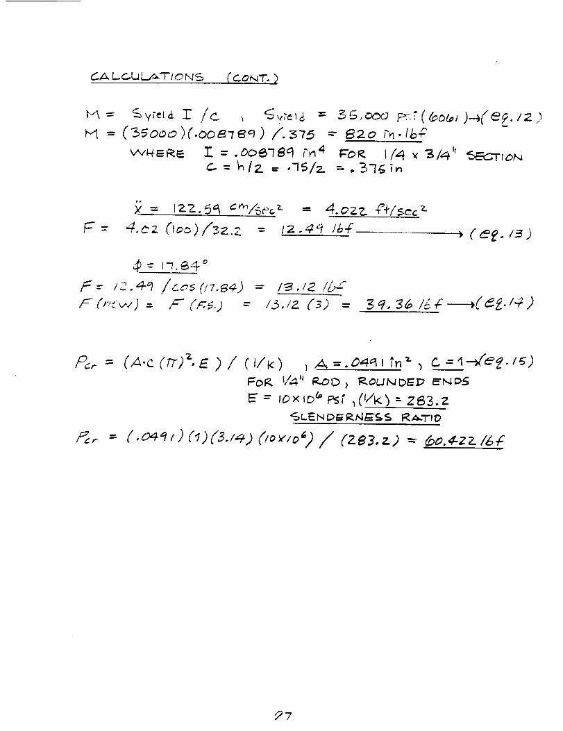
All drive shafts in the system were made of plain carbon steel rod at 1/2 inch in diameterwhich suited a standard size for the inner bore of all components. The crank arms were
sized using the previously calculated maximum torque as the limiting bending moment.Assuming a rectangular cross section of stock 6061 aluminum, the theoretical maximum
bending moment can be calculated (eq.12). This value for theoretical bending moment
should be very oversized compared to the actual maximum transmitted torque to account
for any twisting action or flexing occurring in the arm. A final modification to this
calculation as previously mentioned was to make the entire crank assembly out of steel.An additional calculation was not necessary to perform since steel is stronger and stiffer
and a larger cross section of steel was used than the calculation for aluminum.
To determine the maximum compression that the connecting rod would experience, the
overall maximum robot acceleration must be taken and using Newton's Law and the mass
of the robot, the horizontal force on the slider calculated (eq.13). At this point of
maximum acceleration, at the angle of the connecting rod with the horizontal, the actualmaximum force in the connecting rod was calculated with a factor of safety (eq.14). This
force was compared to the theoretical critical load for column buckling assuming a 1/4
inch 6061 aluminum rod (eq.15). A major change that was undertaken in the construction
was that the connecting rod had to be purposely bent to accommodatea difference inheight between the crank arms and the slider blocks to which they connected. Thealuminum rods used were also upgradedto thicker 3/8 inch diameteraluminum. Althoughthe intentional bend in the rods promote prematurebuckling, having an increaseddiameterand sufficient testing haveensuredthat their strengthwas ample.
Manufacturing
The first step in manufacturing Prototerp IV was to construct a timeline outlining what
would be built when. The timeline proposal is included in Appendix D. The timeline was
relatively closely adhered to during the semester, but minor setbacks and changes were
encountered along the way. The following is an account of the manufacturing processes
and problems encountered resulting in deviations from the schedule.
Manufacturing processes utilized
The following operations were performed on each component:
Gearbox
L-Brackets: Cut to length with aluminum saw; reamed bearing holes; drilled and
countersunk connecting holes; bolted together with additional plate. Mounted
bearings and shafts with components.
Gearbox shafting: Cut to length with band saw; turned one down on lathe for
encoder mounting. Cut keyways with broaching tool on milling machine; cut and
sanded keys. Cut snap ring grooves with lathe.
Sprockets: Cut keys with broaching tool; mounted on shafts.Gears: Mounted on shafts.
Motor: Bolted to channel; mounted with strap.
Encoder mount: Cut channel to length; drilled mounting holes; cut spacers; bolted
channel to gearbox; mounted encoder to shaft with setscrews, to channel with
machine screws, nuts.
Crank Mechanism
Crank shaft discs: Cut with band saw; sanded; drilled center hole; ground down on
lathe after welding; drilled finetune holes.
Crank shafts: Cut to length; weld discs on; clean up weld on lathe; cut keyways
with broaching tool on milling machine; cut and sanded keys; cut snap ring
grooves; drilled; countersunk and tapped center hole. Mounted crankarrn withmachine screws; washer; and nuts.
Crank arms: Cut to size with band saw; sanded; drilled holes. Finetune holes
drilled. Mounted connecting rods with bolt; washer; and rod-end bearing.
Connecting rods: Cut to length; threaded ends with die; mounted rod-end beatings;
cut spacers from aluminum tubing on grinder, tapped leg sliders; bolted to legsliders.
Component Mounts
Bottom plate: Cut with aluminum saw; reamed holes for crankshaft bearing, bigfoot
shaft and motor mount; drilled mounting holes; mounted bearings and shafts.
Milled holes under gearbox bearings, slots for gearbox, weight reduction holes.Mounted plate to chassis with machine screws and nuts.
Top plate: Reamed holes for bigfoot shaft and crankshaft bearings; drilled mounting
holes. Milled holes for weight reduction. Mounted plate to chassis with machinescrews and nuts.
10
Pulley and Cable SystemCable: Cut to length; attachedto legs with cable clamps; cut holes in rod mountingplatesfor cablesto run; ran cablesaroundsheaves;tightenedwith turnbuckles.Sheaves: Made spacers;drilled holes in chassis;mounted sheaveswith machinescrewsand nuts; attachedaluminum sheetmetal with screws.
Deviations from the timelin¢ and original design
Deviations from the timeline and design occurred for a few reasons. First, all of the
necessary materials (rod-end bearings, bolts, washers, etc.) were not always available to
complete the tasks. To subvert this, other tasks were started, or redesign was necessary.
For example, the gearbox channel was originally designed as a C-channel. However, as
this was not available, another design utilizing L-brackets was utilized. This turned out
advantageously, since we were able to ream both top and bottom bearing holes at once byplacing the brackets back to back.
Unexpected problems accounted for some slowdown. For example, the gearbox shaft for
the optical encoder mount was turned down too far, resulting in a broken encoder.
Upon purchase of a new encoder, a new shaft was machined, but had to be built back up
due to the extremely tight tolerance required by the encoder (less than 0.0005 " ondiameter).
In addition, upon mounting the motor, it was found to flex away from the mounting plate.
This was solved simply by attaching a small steel band around the motor to hold it in
place.
Timeline deviations also occurred because precautions were taken. To insure that the crank
mechanism would fit in with the chassis, it was decided to machine the connecting rods
long, thread more than necessary, and walt until the leg sliders were manufactured. This
turned out to be an intelligent decision, since the rods needed to be bent so the bearingswould not be acting at an angle.
Similarly, the pulley placement design was intentionally not solidified until well into
production, since other components' placements were unclear. When the other design was
definite, the pulley placement was designed for minimum frictional losses.
11
Recommendations for Mars Exploration
In order for the driveline mechanism to function properly on the surface of Mars, certain
design changes and additions are essential. The atmospheric and surface conditions on
Mars were studied, and in conclusion temperature variations, dust storms, surface
characteristics, and gravitational effects would have the greatest impact on the driveline
performance.
On Mars, the lowest temperatures occur at the south pole during winter, where they fall as
low as 150 K and the highest temperatures are at the southern midlatitudes in the summer,when midday temperatures reach as high as 300 K. Where the robot lands geographically
makes a lot of difference as far as atmospheric conditions are concerned, therefore the
worst situation is the best design criteria. Because of such large temperature variations,
ductility/brittleness and expansion/contraction characteristics of the material (aluminum and
steel in prototerp IV) used to build the driveline assemblies will be important. It is
recommended to research further and test other suitable materials such as composites,
ceramics, plastics, and other types of metals for use on the driveline mechanism.
The use of lubricants is also affected by temperature and the amount of outgassing. Since
lubricating the chains and gears reduces a lot of friction, it can not be ignored. Ordinary
grease, like the one used on prototerp IV can not be used on Mars because of complicated
thermo-physical reasons beyond the scope of this paper. Instead, it is best to use a NASA
approved and tested synthetic lubricant for aerospace applications called TRIBOLUBE 15.
Coating all gears and driveline components such as the rolling ball bearings with a doublelayer of teflon will help in significantly reducing friction without the use of too much
TRIBOLUBE 15 (costs approximately $600.0 per lb). See Appendix E for specificationsof TRIBOLUBE 15.
According to data and observations collected in recent years, dust storms occur regularly onthe surface of Mars. Most of these storms move with velocities of 14-35 m/s. These
storms are caused by high velocity wind patterns picking up fine grains of sediment.
Knowing this important fact, we would have to cover all bearings (including the ones on
the pulleys) with a cap made of special rubber to stop the fine grains from getting in
between the rolling balls, thus destroying their function. It would also be of benefit to
cover and seal tight the entire midsection of the robot, including the two crank arms, their
connecting rods, and the gearbox with a thin aerodynamic thermal barrier made from light
material. This barrier would not only reduce turbulence caused by high velocity winds, but
that it would also protect the power transmission plant from excessive dust and sand.
Since the temperatures get extremely cold, addition of an electric resistance heater inside
the mentioned barrier would help in maintaining the stability and performance of the motor.
This heater shall utilize the existing robot main battery. As the crank arms rotate, the
connecting rods translate along the sides of the robot, and the best way to cover them is
through the use of a flexible canvas covered with a layer of special rubber (DANDUX,as
supplied to NASA by CR Daniels INC.), similar to the conventional manual transmissionshift boot installed on most cars.
The final concern for the driveline mechanism would be the gravitational effects. These
12
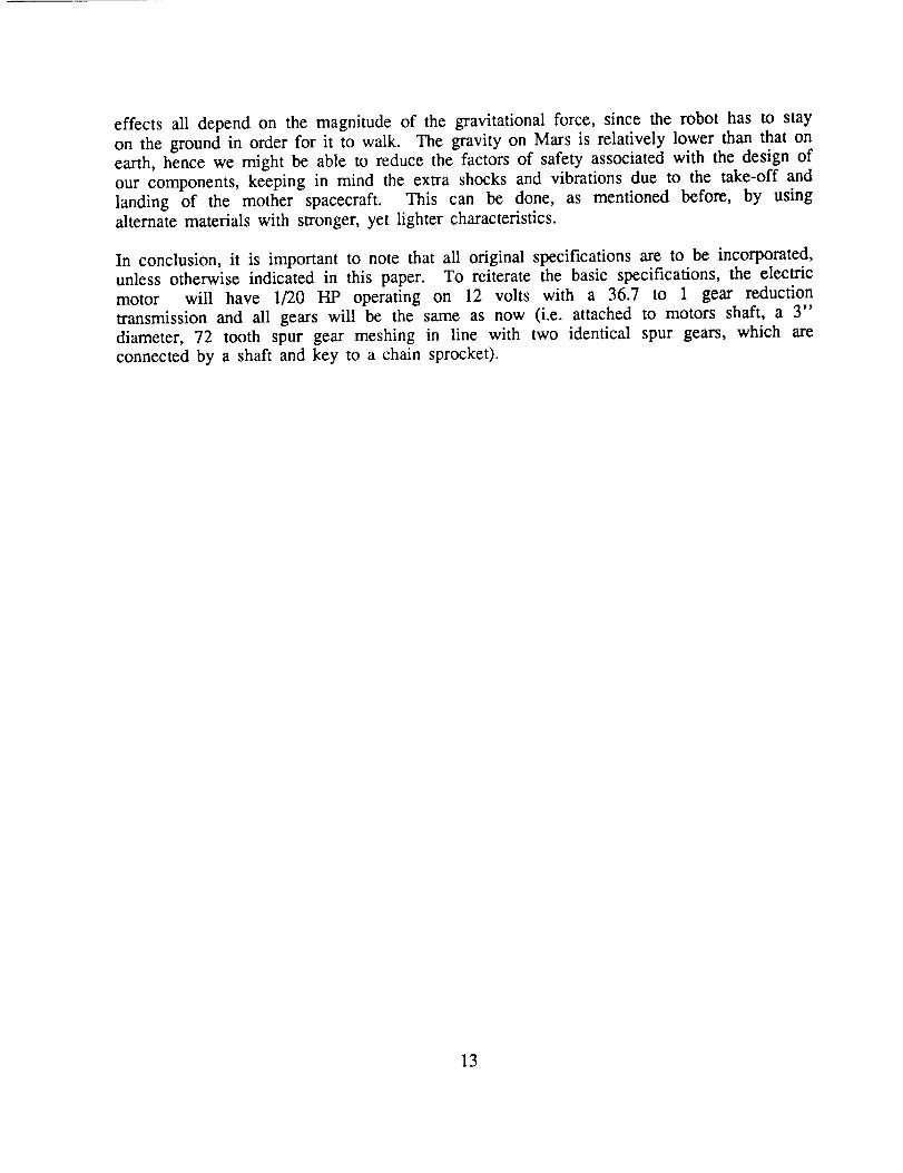
effects all depend on the magnitude of the gravitational force, since the robot has to stay
on the ground in order for it to walk. The gravity on Mars is relatively lower than that on
earth, hence we might be able to reduce the factors of safety associated with the design of
our components, keeping in mind the extra shocks and vibrations due to the take-off and
landing of the mother spacecraft. This can be done, as mentioned before, by usingalternate materials with stronger, yet lighter characteristics.
In conclusion, it is important to note that all original specifications are to be incorporated,
unless otherwise indicated in this paper. To reiterate the basic specifications, the electric
motor will have 1/20 HP operating on 12 volts with a 36.7 to 1 gear reduction
transmission and all gears will be the same as now (i.e. attached to motors shaft, a 3"
diameter, 72 tooth spur gear meshing in line with two identical spur gears, which are
connected by a shaft and key to a chain sprocket).
13
Conclusions
The driveline of Prototerp IV was completed ahead of schedule, allowing the members of
the group to help with other groups. There were no mechanical failures, and the drivemechanism ran smoothly. Upon powering up the robot, it was apparent that the drive
motor was well sized, since the robot's weight was easily accelerated.
In retrospect, the driveline group learned a great deal about design work and project
engineering. There are several guidelines which the group feels are important in future
walking machine project work:
1) Keep the design simple. On any project with a specific deadline, complexity adds to
the probability of error, and makes troubleshooting easier. Although our driveline
design was relatively simple, there were still minor problems that were unaccounted for
which slowed progress.
2) Draw up a parts list early and order parts ahead of time. Lack of components can
slow down progress. Shipping time should also be accounted for.
3) Know the complexity of machine shop processes before you design the robot to use
them. In this case, specialized tooling and expertise was necessary to machine some
driveline components, and one process involved tighter tolerances than our machinery
was capable of.
4) Design for low weight from the outset. The driveline group made modifications to
parts along the way to reduce weight. This possibly could have been averted slightly if
the original design was more weight-conscious.
Overall, the driveline group project was a success. Hopefully the work done by this year's
group can be used to help advance the field of robotics, and help future University of
Maryland students design and construct successful walking robots.
14
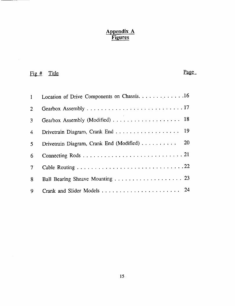
Appendix AFigures
Title
1
2
3
4
5
6
7
8
9
Location of Drive Components on Chassis ....... ...... 16
Gearbox Assembly ........................... 17
Gearbox Assembly (Modified) ................... 18
Drivetrain Diagram, Crank End .................. 19
Drivetrain Diagram, Crank End (Modified) ........... 20
Connecting Rods ............................ 21
Cable Routing .............................. 22
Ball Bearing Sheave Mounting ................... 23
Crank and Slider Models ...................... 24
15
I I
II
.,i:-Or_..,_TzON OI = DI_}v-c
COMPON_Nq'_ ON d.N_,6_S
1
_\\\\\\\\\\\\\\\\_[[[///N/X//
_:_:]:_1
iiiiiil..
-/,I
I
1
i
,,/
\/
', / -_-
x/x/ ,\/\/ i
"(,Ix/\/\/\Z
-_/N
x/
,'/ N• J __
#
\
\
\
0
c-0
LL
amMI.
0
E
x0
(9
mm
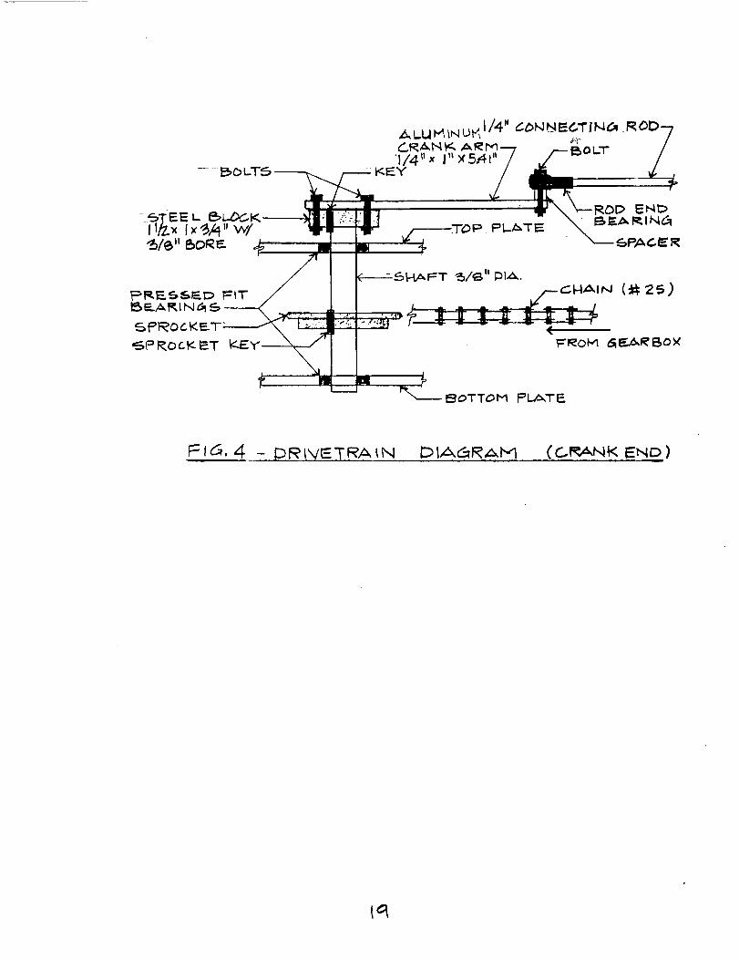
FI_, 4 - D I_I',,/I_TRA_N D_A@RII'd (C.I_kNK END)
u_ _ THRU-_uTS
............. 5.4.1
CA) q-oF ","; _'¢,/
7
l 6NA_'I2,1N_6 _ f CRAW It..Xll I .... 1- Ii !
(1_) 5_ D,_ vrew'
ZEZ:E3
' i '1 1
P I__T IE.. I/4"
Fit. _6- 6RINK A_6EI'-'II_Ly ( _-IE_.F--L )
"2._o
ALUmll NUI'd
T_E,_,_E_END_
ALUMINUM_L_DE_. BLOCK L
T_PPED _UT /I--I_LE
l
TOP VIt_W - [_OD E_ I_F_Z_IN_
Ft5 _- _OkJNEF_TIN(a Ro.D£
21
d)
_'ld_. 7 - CASLE I_OUTINd._
22
11III
I m
I III
B_r-._ET
FI_, q A - CRANK.- _LIDER
2.4
/_...__) = _10 °
Fx(I _,.
F}_,. _l c. - _RAblK- 5LIftER
26
.&p (:_t_..ND'_'X _. - _.ALCL.ILATI 0_I_
E = 4- _-,,c_.
_____(e _'. s;
______(_Z.s-)
' - 4.oZ'l_ 4"_I'_cz
r=- _, 6"IZ
7- _- F× r _ /Z.l,,'_ x 3.8_z
= !.o@4..,._pj ,, _(e_.,,)
_6
r_A D-_U{__-F_ONS (CON'F.)
(l:>:)/%z.z = _._,:# /z,-f
_f
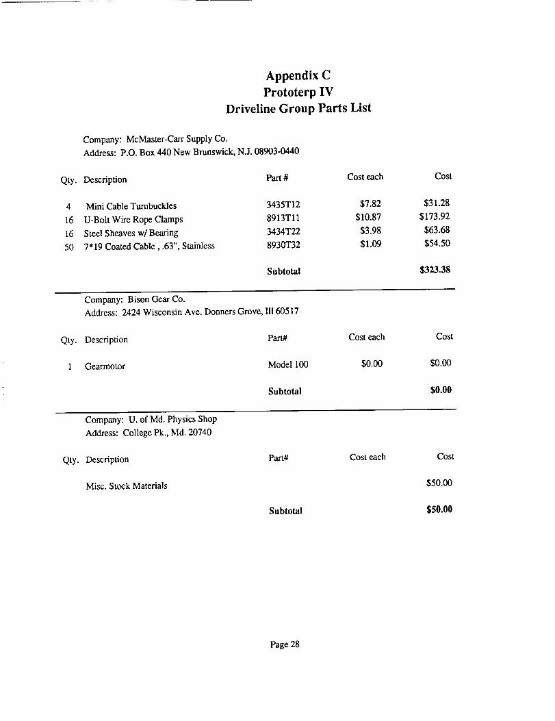
Appendix C
Prototerp IV
Driveline Group Parts List
Company: McMaster-Carr Supply Co.
Address: P.O. Box 440 New Brunswick, N.J. 08903-0440
Qty. Description Part # Cost each
4 Mini Cable Turnbuckles
16 U-Bolt Wire Rope Clamps
16 Steel Sheaves w/Bearing
50 7"19 Coated Cable, .63", Stainless
Cost
3435T12 $7.82 $31.28
8913Tll $10.87 $173.92
3434T22 $3.98 $63.68
8930T32 $1.09 $54.50
Subtotal $323.38
Company: Bison Gear Co.
Address: 2424 Wisconsin Ave. Donners Grove, III 60517
Qty. Description Part#
1 Gearmotor Model 100
Subtotal
Cost each
$0.00
Cost
$0.00
$0.00
Company: U. of Md. Physics Shop
Address: College Pk., Md. 20740
Qty. Description Part#
Misc. Stock Materials
Subtotal
Cost each Cost
$50.00
$50.00
Page 28
Prototerp IV
Driveline Group Parts List
Company: American Bearing
10 Taft Ct. Rockville, Md. 20850
Description
Qty.
4 Rod End Bearings
3 Spur Gears
8 Bearings
4 Sprockets
2 Sprockets
1 #35 Chain, 1 10 ft length
Part# Cost each Cost
Sphereco TR6 $9.41 $37.64
H2472 $19.63 $58.89
7508DLG "IN $12.98 $103.84
35B22-1/2 $12.68 $50.72
35BS11-1/2 $6.60 $13.20
35 RIV $36.20 $36.20
Subtotal $300.49
Total Cost $673.87
Page 29

APPENDIX D
ENME 408
PR_ IV WALKING ROBOT
DRIVELINE TEAM
TIMELINE PROPOSAL
Phase
Io Machine connecting rodMachine crank arm
Connect crank arm to connecting rod
Experiment with machine shop processes
I I. Make gearbox housing, attach bearingsAttach gears to shafts, shafts to housing
III. Attach gearbox to chassis
Approximate due date
Feb. 2(1 week)
Feb. 16
(2 weeks)
Feb. 23
(1 week)
I V. Connect connecting rod assembly to crank shaft Mar. 9
and legs (2 weeks)Help perform testing of legs
V. Mount pulleys to chassis Mar. 16(1 week)
VI. Attach cables Mar. 22
Notes:
Several phases depend on other groups. The following should be checked ornoted:
1. Will the chassis group be ready by Feb. 23 to have the gearbox attached?
2. Will the first leg be complete by Mar. 9?3. The cables are to be attached to the legs as they are finished.
G. Young1/23/90
30
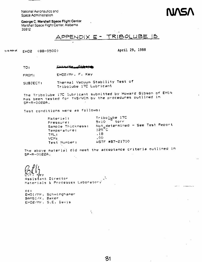
Nat4onal Aeronautics and
Space Administration
George C, Marshall Space Right CantorMarshall Space Flighl Center, Alabama35812
APPF---t',,I Ipl Y E - TRIEBOLUBF__ 15
N/ A
4yIo A_n_: EH02 ( 8B-0500 ) April 29, 198B
TO:
FROM: EHO2/Mr. F. Key
SUBJECT: Thermal Vacuum Stability Test of
Tribolube 17C Lubricant
The Tribolube 17C lubricant submitted by Howard Gibson of EH14
has been tested for TVS/VCM by the procedures outlined in
SP-R-OO22A.
Test conditions were as follows:
Material:
Pressure;
Sample Thickness:
Temperature:
TML:VCM:
Test Number:
Tribo!_be ITC5×10 tort
Notodetermined - See Test _eportle5 c.IB
.OCt
WSTF #87-21710
The above material did meet the acceptance criteria outlined in
SP-R-OO22A.
A__istant Director
MatIerial__ _ Prc, m-e_.es Lmborator_
COl
EHO1/Mr, Schwinghamer
BAMSI /K, Baker
EH02/blr, S, E. De,' is
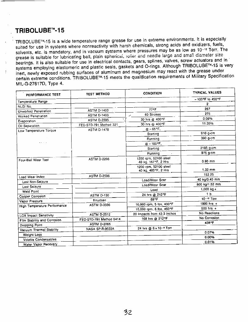
TRIBOLUBET"-15
' TRIBOLUBETM-15 is a wide temperature range grease for use in extreme environments. It is especiallysuited for use in systems where nonreactivity with harsh chemicals, strong acids and oxidizers, fuels,
solvents, etc. is mandatory, and in vacuum systems where pressures may be as low as 10 -'2 Torr. Thegrease is suitable for lubricating ball, plain spherical, loller and needle large and smaTl diameter sizebearings. It is also suitable for use in electrical contacts, gears, splines, valves, screw actuators and insystems employing elastomeric and plastic seals, gaskets and O-rings. Although TRIBOLUBE_-15 is veryinert, newly exposed rubbing surfaces of aluminum and magnesium may react with the grease undercertain extreme conditions. TRIBOLUBETU-15 meets the qualification requirements of Military SpecificationMIL-G-27617D, Type 4.
PERFORMANCE TEST
Temperature Range
NLGINo.
Unworked Penetration
Worked Penetration
TEST METHOD
Low Temperature Torque
ASTM D-1403
ASTM D-1403
CONDITION
77OF
..- 60 Strokes
TYPICAL VALUES
-100°F to 450°F
287
275
@-65°F,
Evaporation ASTM D-2595 ", 30 hrs @ 4000F 0.08o,,b
Oil Separation FED-STD-791 Method 321 30 hrs @ 400°F 11.35O/o
ASTM D-1478
Starting 910 g-cm
Running 390 g-cm
@ - lO0OF,
Starting 3185 g-cm
Running
1200 rpm, 52100 steel
40 kg, 167°F, 2 Hrs
975 g-cm
Four-Ball Wear Test ASTM D-2266
Load Wear Index ASTM D-2596
Last Non-Seizure
0.90 mm
1200 rpm, 52100 steel ,
40 kg, 400°F, 2 Hrs 1.33 mm
152.25
Load/Wear Scar 40 kg/0.40 mm
Load/Wear ScarLast Seizure
Weld Point Load 1,000 kg +
Copper Corrosion ASTM D-130 24 hrs @ 212°F 1 b
Vapor Pressure Knudsen
High Temperature Performance ASTM D-3336
LOX Impact Sensitivity ASTM D-2512
Film Stability and Corrosion FED-STD-791 Method 5414
Dropplng Point ASTM D-2265
Vacuum Thermal Stability NASA SP-R-O022A
Weight Loss
Volatile Condensables
68OF
10,000 rpm, 5 Ibs, 400°F
800 kg11.52 mm
Water Vapor Recover},
10 -'2 Torr
1800 hrs ÷
10,000 rpm, 5 Ibs, 450°F 500 hrs +
20 Impact_ from 43.3 inches No Reactions
168 hrs @ 212°F No Corrosion
4380F
24 hrs @ 6x 10 -e Torr
0.07%
0.00%
0.01%
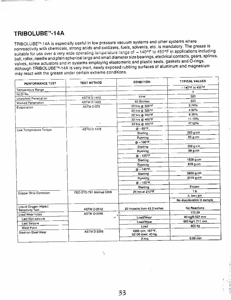
TRIBOLUBET"-14A
TRIBOLUBETM-14A is especially useful in low pressure vacuum systems and other systems wherenonreactivity with chemicals, strong acids and oxidizers, fuels, solvents, etc. is mandatory. The grease issuitable for use over a very wide operat;ng .................... 'L_,,,F_,.",,.,,= 'o"U_ 140°F to ,!_no_ in applications includingball, roller, needle and plain spherical large and small diameter size bearings, electrical contacts, gears, splines,valves, screw actuators and in systems employing elastomeric and plastic seals, gaskets and O-rings.Although TRIBOLUBE'r'_-14A is very inert, newly exposed rubbing surfaces of aluminum and magnesium
may react with the grease under certain extreme conditions.
PERFORMANCE TEST TEST METHOD CONDITION TYPICAL VALUES
Temperature Range - 140°F to 450°F
NLGI No. 1
Unworked Penetration ASTM D-1403 77=F 320
Worked Penetration ASTM D-1403 60 Strokes 333
ASTM D-972 3.74%Evaporation
Low Temperature Torque
Copper Strip Corrosion
ASTM D-1478
FED-STD-791 Method 5309
22 hrs @ 300°F
22 hrs @ 325°F 4.92%
22 hrs @ 350°F 6.39%
22 hrs @ 400°F 11.10o/o
22 hrs@450°F
@ -65OF,
17.52%
Starting 293 g-cm
Running 65 g.cm
@ - IO0OF,
Starting 358 g-cm
Running 98 g-em ......
@ - 125OF
Starting 1528 g-cm.
Running 878 g-cm
@ - 140OF,
Starting 5850 g-cm
Running 2015 g-cm
@ - 150OF,
Starting Frozen
24 hrs at 212°F 1 b
It, bwn stn
No discoloration In sa.m,pieLiquid Oxygen impact - '
Sensitivity Test ASTM D-2512 20 Impacts from 43.3 inches No Reactions
Load Wear Index ASTM D-2596 170.29
,.-°Last Non-seizure
Last Seizure
Weld Point
Load/Wear 80 kg/0.527 mm
Load/Wear 600 kg11.71_ mm
Load
1200rpm, 167°F,
52100 steel, 40 kg,
2 Hrs
Steel-on-Steel Wear ASTM D-2266
800 kg
0.69 mm
References
Michael H. Can', The Surface of Mars. 1981, Yale University Press
Dr. R. Chen, "Kinematic Equations of Motion for a Crank-Slider Mechanism". FallSemester 1989
ENME 488 Fall 1989 Class, Prototerp IV Design Book. 1989, University of Maryland
Thomas A. Mutch, Raymond E. Arvidson, James W. Head.m, Kenneth L. Jones, R.
Stephen Saunders, The Geology of Mars. 1975, Princeton University Press
Shigley, Joseph Edward & Mischke, Charles R., Mechanical Engineering Design /5th
Edition. Equations on Column Buckling, pp. 120-125.
Acknowledgements
We would like to thank John Burke of Bison Gear Co. for his contribution of the maindrive motor.
We would also like to express thanks to our advisors, Dr. Azarm, Dr. Tsai, and Mark
Uebel for their contributions, which are too numerous to begin to list here.
34

APPENDIX C:
LEGS
WALKING ROBOT ENME 408
Leg Group - Final Report
Bob OlsonMani OlivaJim Bielec
David HartsigBob Rose
May 7, 1990
Introduction
The events in this year's walking robot competition required the leg assembly to
be capable of variable stride, climbing/descending stairs, turning, and autonomous
activities. The Prototerp IV's leg assembly was designed and constructed to be
lightweight, strong, and achieve uniform motion to minimize the loss of momentum.
Due to the requirements of the competition, several specifications had to be met. First,
a vertical displacement of 16 inches was required so that the robot could easily climb
and descend the stairs. Second, a 3 inch per second vertical displacement with a 10
inch horizontal displacement was necessary so that the robot could obtain a maximum
walking velocity and still manage to walk between the reflective stripes positioned on
the floor surface. A slower rate of vertical displacement would result in a leg not
clearing the ground during a stride. Finally, the leg assembly had to satisfy conditions
so that material failures were minimized without over designing the robot to the point
where performance was sacrificed. Each leg had to be designed to withstand
potential loads of 50 pounds, as well as bending and shear stresses resulting from the
vertical and horizontal acceleration/deceleration of the robot.
The University of Maryland has experimented with other leg assembly designs
in previous years. A "grasshopper" type leg proved to be very successful for walking in
stride but had difficulties in climbing the stairs. These legs forced the robot chassis to
tilt backwards when climbing the stairs. As a result, the center of mass of the entire
robot assembly was shifted and the robot would fall backwards. In addition, the
walking characteristics of these legs produce nonuniform motion and result in large
losses of momentum. Another leg assembly used by the University was a telescoping
leg similar to this year's design. These legs experienced slow strides and did not have
adequate vertical displacement to climb the stairs.
A telescoping leg assembly with a motor for each leg was chosen this year as a
result of the school's prior experience in this competition. This design allows the legs
to obtain greater vertical displacement for climbing the stairs. In addition to the leg
assembly, an eight legged robot was chosen so that the robot will always have 4 legs
on the ground. In addition to the stability that having 4 legs on the ground while
climbing the stairs produces, the robot experiences a smoother and more stable stride
at all times. The choice of this year's legs also allow the robot to be adapted to uneven
terrain since each leg can be controlled to be at a different displacement.
Prototerp IV's leg assembly has been designed around the premise that the
machine will always be resting on four of its eight legs while walking. This approach to
the walking problem provides excellent stability during all phases of maneuvering.
During a typical walk maneuver, the first set of the machine's four legs are supporting
all of the weight while the second set of four legs is transitioning to the next position.
Once this position is reached, the second set of legs°support the machine while the
first set then moves to the next position. Since all eight legs are coupled together and
are horizontally translated by one motor, the horizontal motion of the machine is
continuous. The transitioning set of legs remain above the supporting set of legs due
to the vertical telescoping design of the legs. This vertical telescoping motion is
adjusted by a single motor that is attached to the top of each leg. The vertical and
horizontal drive mechanisms achieve the lift and translate motion that enable the
machine to walk. The following description contains the basic sequence that
constitutes a step. The typical walk cycle has the machine initially supported by one
set of legs. The other set is moving horizontally at a level of about three inches above
the floor. When the machine reaches its desired horizontal position, the transitioning
legs are lowered and the supporting legs are then raised and begin to transition to the
next desired horizontal position.
Vertical translations of the legs are made possible by a telescoping design that
2
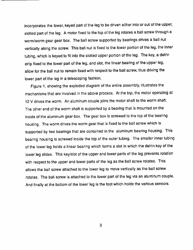
incorporates the lower, keyed part of the leg to be driven either into or out of the upper,
slotted part of the leg. A motor fixed to the top of the leg rotates a ball screw through a
worm/worm gear gear box. The ball screw supported by bearings drives a ball nut
vertically along the screw. This ball nut is fixed to the lower portion of the leg, the inner
tubing, which is keyed to fit into the slotted upper portion of the leg. The key, a delrin
strip fixed to the lower part of the leg, and slot, the linear bearing of the upper leg,
allow for the ball nut to remain fixed with respect to the ball screw, thus driving the
lower part of the leg in a telescoping fashion.
Figure 1, showing the exploded diagram of the entire assembly, illustrates the
mechanisms that are involved in the above process. At the top, the motor operating at
12 V drives the worm. An aluminum couple joins the motor shaft to the worm shaft.
The other end of the worm shaft is supported by a bearing that is mounted on the
inside of the aluminum gear box. The gear box is screwed to the top of the bearing
housing. The worm drives the worm gear that is fixed to the ball screw which is
supported by two bearings that are contained in the aluminum bearing housing. This
bearing housing is screwed inside the top of the outer tubing. The smaller inner tubing
of the lower leg holds a linear bearing which forms a slot in which the delrin key of the
lower leg slides. This key/slot of the upper and lower parts of the leg prevents rotation
with respect to the upper and lower parts of the leg as the ball screw rotates. This
allows the ball screw attached to the lower leg to move vertically as the ball screw
rotates. The ball screw is attached to the lower part of the leg via an aluminum couple.
And finally at the bottom of the lower leg is the foot which holds the various sensors.
3
Design
Unchanged designs
At the beginning of the semester, we started working on the robot from the
designs arrived at during the previous semester (fall '89) in ENME 488. These
designs contained details to construct all of the components for the legs. The design
process continued with the implementation of the prototype, where designs had to be
changed for various reasons. Details were seen when the parts were being made that
were sometimes overlooked in the preliminary design phase. Also, the previous class
designed with little or no knowledge of machining and manufacturing. Our group soon
learned its capabilities and limitations in manufacturing which led to many design
changes.
Even though it was necessary to redesign many components, a few parts
remained unchanged from the specifications arrived at last semester. This section will
briefly present these components with the details centering around the manufacturing
and implementation of these parts. For a more detailed explanation of the design and
engineering aspects, please refer to the final design report of ENME 488.
Ball Screw:
The ball screws were received as raw stock and cut to lengths of 24 inches.
Because the ball screws were donated some machining was required to the ends of
the screws. This allowed us to custom machine the ends to fit the bearings we chose
for our application, but required difficult machining. The main problem in machining
the screws was the hardness of the steel. We learned that the screws were heat
treated to a Rockwell hardness of approximately 60 to 65. Several options became
apparent after asking a few professional machinists their opinion of the best way to
turn down the ends of the screws. These options were to anneal the ends of the ball
4
screws, to grind the ends, or to machine using a carbide tip bit. The decision was
made to anneal the screws by heating the end with an acetylene torch until red hot
and then placing them in sand to cool slowly. This is what the manufacturer
recommends in the ball screw catalog, and it proved to soften the steel sufficiently to
machine. The ends were then turned down to a diameter of 3/8" and then were filed
and sanded to precisely fit the bearings. This filing and sanding was necessary
because the lathe cut a slight taper along the length of the end.
Tvbes and Linear Bearing,_:
The aluminum tubing used for the inner and outer columns of the legs serve as
the vertical support structure of the leg and house the ball screw. These tubes were
sized to standard tube dimensions that were strong enough to support the weight of
the machine and would fit around the outside and inside of the linear bearing for the
outer and inner columns, respectively. The linear bearing proved to fit tightly inside the
outer column and required only one small set screw placed through the tube into the
groove around the circumference of the bearing. The set screw also tightens the
bearing around the inner tube. Care should be taken to prevent over-tightening which
would result in binding.
B_fl Nut / Inner Column Adapter:
The purpose of this adapter is to connect the ball nut to the inner column since
their dimensions are not compatible. One end of the adapter has an inner diameter to
match the diameter of the threads on the ball nut. Three set screws placed through the
adapter against the threads proved to give sufficient strength and stability since the
only stresses seen by these screws is due to the weight of the inner column. The other
end of the adapter has an outer diameter which matches the inner diameter of the
5
inner column. Three screws were also used, and were placed through the tube and
threaded into the adapter.
otor_ °
The motor chosen last semester was the Pittman 9412 19v, with a rated torque
of 2.55 oz-in with a built-in Hewlett-Packard 256-Line zipper encoder. We were not
certain at the start of manufacturing if this torque would be enough to supply the
1.771b-in torque required of the ball screw after gear reduction. The first goal of our
group was to test this motor to see if the power was adequate before placing an order
for the motor/encoder packages. A primitive test apparatus was constructed using the
same ball screw and gearing design for use in the leg. The test proved successful and
the motors were ordered. Later tests using real leg assemblies were also successful,
although slow performance at 12 volts forced us to increase the voltage to 18v. This
gave enough power and speed for the vertical motion of the machine.
Redesigns
When the manufacturing of parts started, many problems arose due to
machining limitations and design flaws. It soon became apparent that the design from
last semester, which was thought to be sound, was in fact far from that. From our
experiences, we learned that a design is definitely not finished until a prototype has
been completed.
During the building of the legs for Prototerp IV, a process of redesigning
occurred. These redesigns were a result of the problems stated above and of insights
gained as machining skills improved. This redesign-while-manufacturing process was
applied to all of the leg components discussed in this section. Details here also center
around the manufacturing and implementation of the components. For a more
6
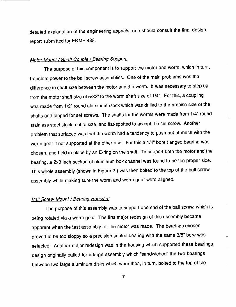
detailed explanation of the engineering aspects, one should consult the final design
report submitted for ENME 488.
MotQr Mount / Shaft Couple / Bearing S_pport:
The purpose of this component is to support the motor and worm, which in turn,
transfers power to the ball screw assemblies. One of the main problems was the
difference in shaft size between the motor and the worm. It was necessary to step up
from the motor shaft size of 5/32" to the worm shaft size of 1/4". For this, a coupling
was made from 1/2" round aluminum stock which was drilled to the precise size of the
shafts and tapped for set screws. The shafts for the worms were made from 1/4" round
stainless steel stock, cut to size, and flat-spotted to accept the set screw. Another
problem that surfaced was that the worm had a tendency to push out of mesh with the
worm gear if not supported at the other end. For this a 1/4" bore flanged bearing was
chosen, and held in place by an E-ring on the shaft. To support both the motor and the
bearing, a 2x3 inch section of aluminum box channel was found to be the proper size.
This whole assembly (shown in Figure 2 ) was then bolted to the top of the ball screw
assembly while making sure the worm and worm gear were aligned.
Ball Screw Mount / Bearing Housing:
The purpose of this assembly was to support one end of the ball screw, which is
being rotated via a worm gear. The first major redesign of this assembly became
apparent when the test assembly for the motor was made. The bearings chosen
proved to be too sloppy so a precision sealed bearing with the same 3/8" bore was
selected. Another major redesign was in the housing which supported these bearings;
design originally called for a large assembly which "sandwiched" the two bearings
between two large aluminum disks which were then, in turn, bolted to the top of the
7
outer leg column. This design was more complex than necessary, and would also be
very difficult to manufacture. The redesigned bearing housing consists of a smaller, 2"
round aluminum stock which would then be sandwiched by the bearings and held in
place by an E-ring placed in a groove on the ball screw. This whole assembly could
then be placed inside of the outer leg column as shown in Figure 3.
Inner Column Key:
To facilitate the vertical motion of the leg, it was necessary to keep the ball
nut/inner leg column from rotating. Originally designed to do this was a hollow,
aluminum key running the length of the inner column which rode in a complex roller
guide bolted to the bottom of the outer leg column. This design was too complex for
the simple task which it performed. Since the torque necessary to drive the ball screw
is relatively small (about 2 in-lbs), we were able to use a solid delrin key which could
be guided directly by the opening in the linear bearing at the bottom of the leg. The
delrin key proved to be easy to manufacture and provided a relatively smooth, low-
friction operation.
In the original design, the wires from the sensors at the bottom of the leg would
run inside the hollow key to the top of the leg. Instead of doing this, we simply glued a
length of ribbon cable to the front face of the key. From there, the cable was routed out
the top of the leg, making sure to leave enough slack on the inside of the tube for full
extension of the leg.
Slider Housing:
The purpose of the slider housings is to connect the telescoping legs to the
body and facilitate horizontal motion. It is a simple structure which clamps around the
base of the outer leg column and slides horizontally on 1/2" hardened steel rods. To
8
reduce friction, linear ball bushings are mounted in the housings and held in place
with snap rings. Two housings per leg are used and are spaced approximately four
inches apart on the outer leg with the bearings on opposing sides. The original design
called for the housings to be made from a single, solid slab of aluminum, 1 1/2" thick
with a 2 1/4" hole drilled through it to mount the leg column. It was soon learned that
this hole would be extremely difficult to machine, and required tools that were
unavailable to us. An alternate design was quickly developed which consisted of two
halves radiused to match the diameter of the tubing. These two halves were then
bolted together, clamping around the leg tube as shown in Figure 5. The manufacture
of these components was both time consuming and labor intensive.
FQot and Sensors:
The purpose of the foot is to provide a structure to mount contact switches and
and infrared detectors at the bottom of the legs. The foot also supplies a contact pad
between the inner leg column and the terrain. Original designs called for a complex
aluminum block with pads glued to the bottom. For a simpler design, a trip to the local
hardware store yielded rubber caps which fit over the ends of the leg tubes. Holes
were drilled in the bottom of these caps where the contact switches could be mounted.
This gave a flexible mount which eliminated any problems of bottoming out and
damaging the switches. The original switches were also replaced with ones having a
greater over-throw to help prevent bottoming out. The infrared sensors were mounted
to a piece of delrin that was then bolted to the inside of the leg tube. A hole was drilled
in the bottom of the pad to provide a window for the detector to look through.
Recommended Design Improvements
Based on all of the improvements made to the initial design which eventually
9
culminated into the present robot, it was decided that designs could be altered to
produce a better final product. Some of these design improvements include changes
in component selection, product manufacturing and assembly, and the overall design.
The suggestions for improvement that will be made are based on experience gained
through the development and assembly process. These ideas accumulated as we
assembled the legs and discovered better ways to accomplish certain tasks or
discovered that a better choice in a particular component would result in better
performance. All of the modifications that we came up with were in response to the
question: "If we could do it all over again, what would we do differently?" By
answering this questions and implementing the resulting modifications into a new and
all encompassing design, a superior design and final product will result.
The most crucial items that would be changed are aimed at resulting in the
enhanced performance of the present robot. These items are the reduction of weight
throughout the leg components, a non back-driving worm/worm gear combination, and
a more frictionless slotted key. The improvement of each of these items would vastly
improve the performance of the robot.
By first reducing the weight of each leg, which comprises about half the weight
of the entire robot, we immediately improve the effective performance of the robot. The
load on the leg motors would be decreased giving them a greater margin of safety and
a more effective power to weight ratio. The implementation of this task is both easy
and inexpensive. For starters, materials with smaller dimensions could be used.
Smaller leg tubes or tubes with smaller thicknesses could be used for the legs.
Another way to reduce the weight would be to reduce the size of the present
components resulting in lighter c_mponents. Additional mass could be trimmed off of
the existing components by cutting off extra or non-crucial material mass. For
instance, the legs could be perforated by drilling holes in them to eliminate mass and
10
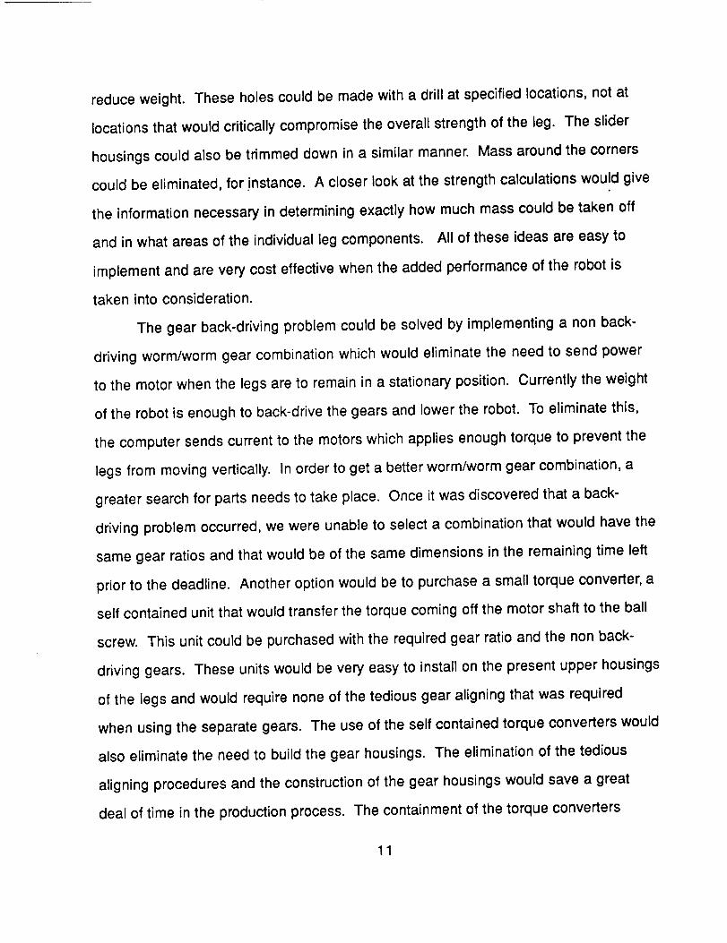
reduce weight. These holes could be made with a drill at specified locations, not at
locations that would critically compromise the overall strength of the leg. The slider
housings could also be trimmed down in a similar manner. Mass around the corners
could be eliminated, for !nstance. A closer look at the strength calculations would give
the information necessary in determining exactly how much mass could be taken off
and in what areas of the individual leg components. All of these ideas are easy to
implement and are very cost effective when the added performance of the robot is
taken into consideration.
The gear back-driving problem could be solved by implementing a non back-
driving worm/worm gear combination which would eliminate the need to send power
to the motor when the legs are to remain in a stationary position. Currently the weight
of the robot is enough to back-drive the gears and lower the robot. To eliminate this,
the computer sends current to the motors which applies enough torque to prevent the
legs from moving vertically. In order to get a better worm/worm gear combination, a
greater search for parts needs to take place. Once it was discovered that a back-
driving problem occurred, we were unable to select a combination that would have the
same gear ratios and that would be of the same dimensions in the remaining time left
prior to the deadline. Another option would be to purchase a small torque converter, a
self contained unit that would transfer the torque coming off the motor shaft to the ball
screw. This unit could be purchased with the required gear ratio and the non back-
driving gears. These units would be very easy to install on the present upper housings
of the legs and would require none of the tedious gear aligning that was required
when using the separate gears. The use of the self contained torque converters would
also eliminate the need to build the gear housings. The elimination of the tedious
aligning procedures and the construction of the gear housings would save a great
deal of time in the production process. The containment of the torque converters
11
would be an added favorable feature especially if the robot were to operate in
environments that would be corrosive to the gears. The only major disadvantage of
these units are their cost which is generally five time the cost of the separate gears.
The next change to be incorporated would be the delrin key slot arrangement of
the lower leg. Currently the delrin key rubs against the inside edge of the steel linear
bearing in which it rides when the leg is translated vertically. This rubbing causes the
metal to dig into the delrin key and shaves off pieces of the delrin creating debris that
could foul the ball screw/ball nut mechanism which may become a problem after
extended use. To prevent this contact, the linear bearing could be outfitted with a
plastic covering that would serve as a contact point on the bearing. This plastic cover
could be mounted on the linear bearing prior to assembly. The major objective of the
plastic covering would be to cover the sharp edges of the metal linear bearing and to
create a plastic on plastic interface for the key to ride.
The three listed changes would be very easy to implement and at costs well
worth the benefits they provide. Future designs and prototypes should take these
suggestions into consideration to insure the greatest attainable performance.
12
Conclusions
As a group, we each feel that we learned a great deal about the total design
process. Designs that looked good on paper did not always look so great once we got
to the machine shop. Despite all of the limitations that faced us during the design and
construction of the legs, we accomplished our task according to our original schedule.
Although we discovered several improvements that could be made in the future, the
legs that were built this semester met all of the functional requirements and performed
well.
Special thanks go to Bob Anders and Mark Uebel for their daily support and
patience throughout the semester. We would also like to thank Dr. Azarm and Dr. Tsai
for their consultation.
13
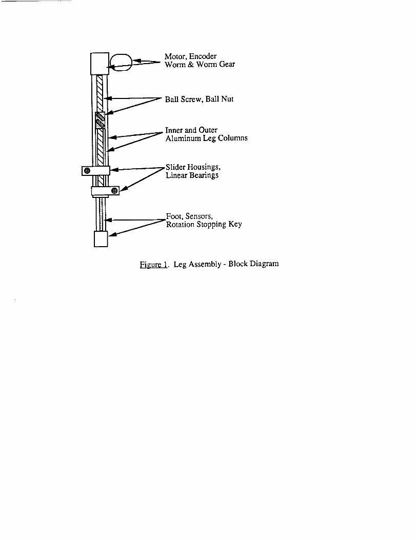
[O
m
Motor, EncoderWorm & Worm Gear
xx Ball Screw, Ball Nut
_ Inner and Outer
,,..,-."_'_ Aluminum Leg Columns
_j Slider Housings,
Linear Bearings
.., Foot, Sensors,
.__"'"fRotation Stopping Key
Figure 1. Leg Assembly - Block Diagram
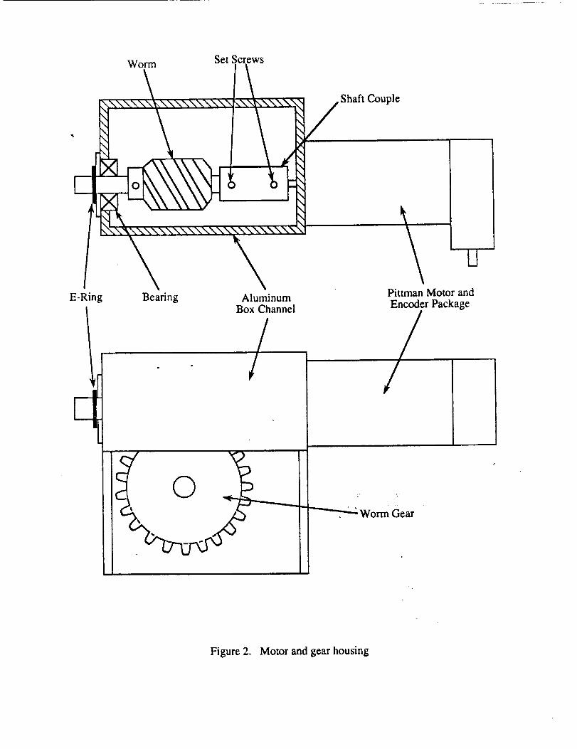
Wom_ SetScrews
E-Ring Bearing AluminumBox Channel
/
Shaft Couple
Pittman Motor and
Encoder Package
Worm Gear
Figure 2. Motor and gear housing
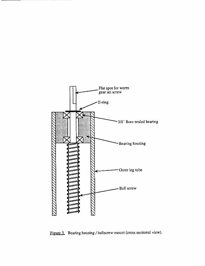
II
" i!ii!i!i!ii!i!!iiiiiiiiiiiiiiii\\ i!iiiiiiiiiiiiiiiiiiiiiiilililiiii
\ ............................ii!i!l\ _i_ii!i_iii!iiiiiiiiiililili!:i:!!\ !ii..:..:iiit!iii!iiiiiii_i!iiii_
\ II\ I\\ i\ i\\ i\ I\\ i\ i\
\
\ I\ I\
\ I
\ •\ m\\ l\ s
-_._.....___._ Flat spot for wormgear set screw
L.
IIi
!I]
j E ring
?" _ Bore sealed bearing.......... _, 3/8".......... \
]]]_]]i]]i \
\..........
I!:!:::_::::: \
\ Bearing housing\\\\\
Ball screw
Figure 3. Bearing housing / ballscrew mount (cross sectional view).
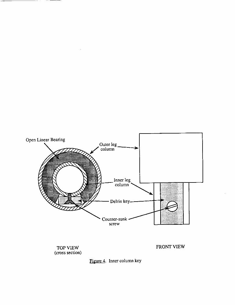
OpenLinearBearing
,, Oo_e__ ___t_ __/1 Inner leg
cilumn _'_ }iii ii
TOP VIEW
(cross section)
FRONT VIEW
Figure 4. Inner column key
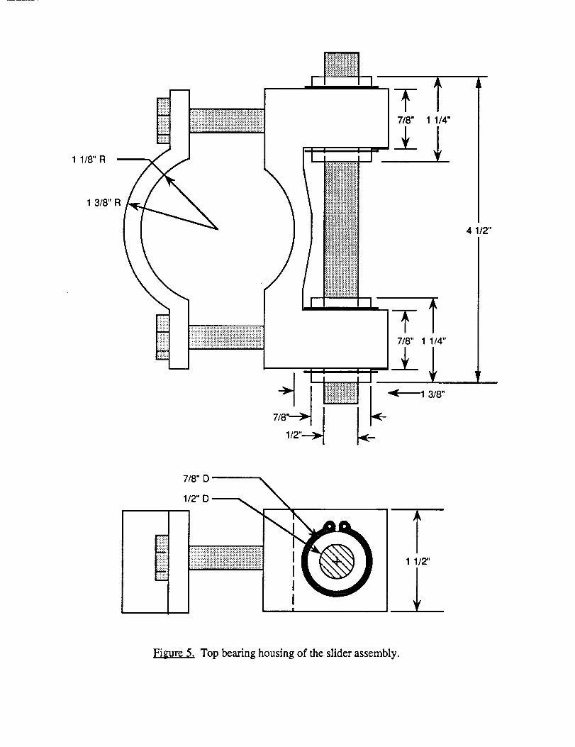
1 1/8" R
1 3/8"R
iiiiiii!iiiiiiii!iiiii!iFi!iiiiiiiiiiiiiiiiii!iiiiiiiiiiiiiiiii!iiiiiiiiiiill!::?:9{9!:!:{:_:_:_:_:!:i:_:!:!:!:!:!:!:!:!:!:!:{:!:!:!:!:!:!:!:!:i:
1/2"--.--_
4 1/2"
'r
7/8" D
1/2" D
Figure 5. Top bearing housing of the slider assembly.

APPENDIX D:
CONTROL HARDWARE
John Neubert
Ladan KimiayiGeorge RyanArte DunningTed McCord
Tom Richmond
Abstract
The control system of the University of Maryland Walking Robot is based on a
closed loop feedback system, a first of its kind at the University of Maryland. In this
configuration information is constantly being exchanged between the Intel 87C1£6KB
microprocessor and the walking robot. The robot has eight legs, each of which are
independently controlled both horizontally and vertically through the sensory
feedback system.
The encoders on the 8 leg motors, the bigfoot motor and the main drive motor
all send to and receive information from the controller. In addition the contact
switches, the infrared sensors on the legs, the long range sensor (which is mounted in
front of the robot), and the hockey stick provide information about the robots
environment. Therefore, at all times the computer is aware of the horizontal and
vertical location of each leg, as well as the direction in which the motors are turning.
This information allows the computer to determine the absolute position of the robot.
Introduction
The purpose of the Walking Robot Control Hardware group was to design, test,
and fabricate the control system for the Walking Robot. The members of the group set
about fabricating the computer from a design that was proposed the previous
semester. During construction of the computer many obstacles were encountered
which inevitably resulted in numerous design changes from the original plans.
The control system of this robot uses an Intel 87C196KB Microcontroller. This
is a 16-bit CHMOS high performance controller with time average for a typical
applications of 0.51_s- 1.5_s. For our application ports 1 through 4 will be used as
primary information flow between the computer and the robot.
The exchange of data is accomplished through the data lines and address lines
via ports 3 and 4 of the processor. The memory mapping was divided into four primary
groups: address' C00F-FFFF are dedicated to RAM; address' 8000-BFFF are
dedicated to the inputs from the motors and leg position sensors, the outputs are from
the microprocessor to the motor and leg control; address' 4000-7FFF are dedicated to
ROM; finally address' 0-3999 are dedicated to on-chip ROM.

Experimental procedure
Due to the complexity of the control system it was necessary to divide the
computer into subsystems. The computer system was divided into the following
subsystems: Microprocessor and Main Memory; Input/Output; Pulse Width
Modulators (PWM); Motor Control; and Leg Control.
Microprocessor and Main Memory
The Intel 87C196BK microprocessor was chosen as the Central Processing
Unit. The 68 pin LCC socket was mounted on a printed circuit board. This was
chosen because of the difficulties associated with wire-wrapping in a densely packed
environment. In addition, extensive prior experience with soldering dictated this
choice as the logical alternative to wire wrapping. Problems associated with this
fabrication technique were a result of several design changes encountered during the
course of construction. The decision to use the 87C196BK instead of the 80C196BK
resulted in the need for extensive reconstruction late in the semester. This resulted in
damage to the printed circuit board and existing wiring.
The Intel 87C196BK microprocessor uses four 8-bit ports (busses) to send and
receive data. Port 1 was used to control the PWM's and through them the speed and
direction of the main motor and the leg motors. Port 2 was used in conjunction with
Port 1 for controlling the PWM's. Ports 3 and 4 were used as a data bus between the
main memory and the multiple sensors on the robot.
Testing of the microprocessor and main memory was done by using the ICE96
emulator supplied by Intel. The Ports and RAM were tested by writing a bit or a word
to the emulator which in turn would write to RAM. The output from the CPU was
observed using a "window" or by reading the same address location. If all address
locations were functioning properly any 16 bit combination could successfully be
written to and read from any address location.•_1__
Input/Output
The 20 chips used for the purpose of latching information from the sensors and
then sending information to the computer were all wire-wrapped on three perforated
boards. The data from the sensors was stored in the buffer chips and then transmitted
to the microprocessor when the 8 bit buffers address was enabled. The data was then
transferred via ribbon cable on data lines 0 through 15. This information was received
at data Port 3 and 4 on the microprocessor.
The Texas Instruments SN74HC244 Octal Buffers are high speed
Complementary Metal-Oxide Semiconductors (CMOS). These devices are used to
receive and store 8 input bits from the sensors until the microprocessor requests the
information stored in the buffer.
Testing of the Input/Output was done by inputting a waveform into the buffer,
then enabling the buffer and observing the output. In this way the wiring and
operation of the buffer was insured prior to final assembly of the computer.
Pulse Width Modulators
The PWM's were used to individually control the speed and direction of the leg
motors, the main drive motor, and the bigfoot motor. This was necessary because of
an unforeseen backdriving problem in the telescoping legs which could not be solved
mechanically. The PWM's control motor speed by varying the frequency of the pulse
train to the motor. As the frequency of the incoming modulated signal increases the
speed of the motor increases proportionally. By varying the input signal from 0 to 255
in discrete intervals, the motor speed can be incrementally adjusted from 0 to max.
motor speed. The PWM's were tested by sending a control signal to the PWM's via
the main memory board from the emulator and by observing the output on a digital
oscilloscope.
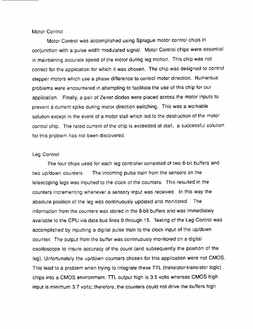
Motor Control
Motor Control was accomplished using Sprague motor control chips in
conjunction with a pulse width modulated signal. Motor Control chips were essential
in maintaining accurate speed of the motor during leg motion. This chip was not
correct for the application for which it was chosen. The chip was designed to control
stepper motors which use a phase difference to control motor direction. Numerous
problems were encountered in attempting to facilitate the use of this chip for our
application. Finally, a pair of Zener diodes were placed across the motor inputs to
prevent a current spike during motor direction switching. This was a workable
solution except in the event of a motor stall which led to the destruction of the motor
control chip. The rated current of the chip is exceeded at stall, a successful solution
for this problem has not been discovered.
Leg Control
The four chips used for each leg controller consisted of two 8-bit buffers and
two up/down counters. The incoming pulse train from the sensors on the
telescoping legs was inputted to the clock of the counters. This resulted in the
counters incrementing whenever a sensory input was received. In this way the
absolute position of the leg was continuously updated and monitored. The
information from the counters was stored in the 8-bit buffers and was immediately
available to the CPU via data bus lines 0 through 15. Testing of the Leg Control was
accomplished by inputting a digital pulse train to the clock input of the up/down
counter. The output from the buffer was continuously monitored on a digital
oscilloscope to insure accuracy of the count (and subsequently the position of the
leg). Unfortunately the up/down counters chosen for this application were not CMOS.
This lead to a problem when trying to integrate these TTL (transistor-transistor logic)
chips into a CMOS environment. TTL output high is 3.5 volts whereas CMOS high
input is minimum 3.7 volts; therefore, the counters could not drive the buffers high
consistently. The solution to this problem was to add pull-up resistors to every output
of the counters to ensure a solid five volt high reading. This solution worked well, but
as there are 18 8-bit counters, they required 144 pull-up resistors. The solution was
time consuming to implement.
Experimental results
The control system was successfully tested and is fully operational for use with
the Walking Robot. To date the motor control circuitry has not been successfully
redesigned.
Discussion
Suggested methods for solving the motor control problem are redesigning of the
motor control circuit or limiting the travel of the telescoping leg to prevent motor stall.
Travel limiting can be accomplished in software by closely monitoring the leg
counters and never allowing the legs to reach their extreme positions, either up or
down.
If the problems associated with backdriving of the leg motors were reconciled
the necessity of the PWM's would be eliminated. This would result in less power
consumption, reduce the overall cost and complexity of the design, and reduce the
possibility of system failure.
Application of the Robot to the Martian environment
For the robot to successfully operate under the extreme environmental
conditions associated with the Martian environment the control hardware would need
extensive modification. The extremely low temperature conditions on Mars would
necessitate some method of temperature control for the control components. In
addition the control computer should be built on a custom made printed circuit board
and then sealed to prevent intrusion of the Martian environment. Position sensors for
the robot would need to be redesigned to incorporate sensing of the rough Martian
landscape. Additional sensors would be necessary to insure the safety of the robot
by monitoring the height and depth of the surrounding terrain, the pitch and roll of the
robot, and any other potentially hazardous terrain features.
Conclusions
The successful building of a complex microprocessor-based closed feedback
system provides the groundwork for future applications of this technology to the
Walking Robot Project. The problems which were encountered and solved indicate
the feasibility of continuing this level of complexity for the Walking Robot control
system.

APPENDIX E:
CONTROL SOFTWARE

SOFTWARE GROUP
May 7, 1990
Robert Hails
Darya Nabavian
Tejpal Rehncy
Daniel Sacks
Tim Strakna
Abstract
This' paper discusses the software strategies currently employed in the
University of Maryland's 1990 walking robot, the Prototerp IV. It concerns itself
primarily with problems encountered in the interface between mechanical and
electrical hardware and the larger macro routines that have been designed. The
discussion then turns to the subject of software modifications to make placement on
the surface of Mars a feasible concept. Redesign includes intelligence systems,
navigation, performance monitoring and a secondary mode of travel.
g
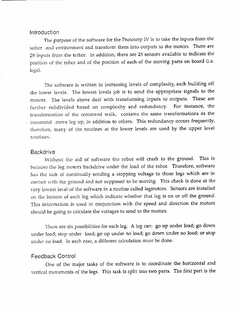
Introduction
The purpose of the software for the Prototerp IV is to take the inputs from the
tether and environment and transform them into outputs to the motors. There are
29 inputs from the tether. In addition, there are 25 sensors available to indicate the
position of the robot and of the position of each of the moving parts on board (i.e.
legs).
The software is written in increasing levels of complexity, each building off
the lower levels. The lowest levels job is to send the appropriate signals to the
motors. The levels above deal with transforming inputs to outputs. These are
further subdivided based on complexity and redundancy. For instance, the
transformation of the command walk, contains the same transformations as the
command move leg up, in addition to others. This redundancy occurs frequently,
therefore, many of the routines at the lower levels are used by the upper level
routines.
Backdrive
Without the aid of software the robot will crash to the ground. This is
because the leg motors backdrive under the load of the robot. Therefore, software
has the task of continually sending a stopping voltage to those legs which are in
contact with the ground and not supposed to be moving. This check is done at the
very lowest level of the software in a routine called legmotors. Sensors are installed
on the bottom of each leg which indicate whether that leg is on or off the ground.
This information is used in conjunction with the speed and direction the motors
should be going to calculate the voltages to send to the motors.
There are six possibilities for each leg. A leg can: go up under load; go down
under load; stop under load; go up under no load; go down under no load; or stop
under no load. In each case, a different calculation must be done.
Feedback Control
One of the major tasks of the software is to coordinate the horizontal and
vertical movements of the legs. This task is split into two parts. The first part is the
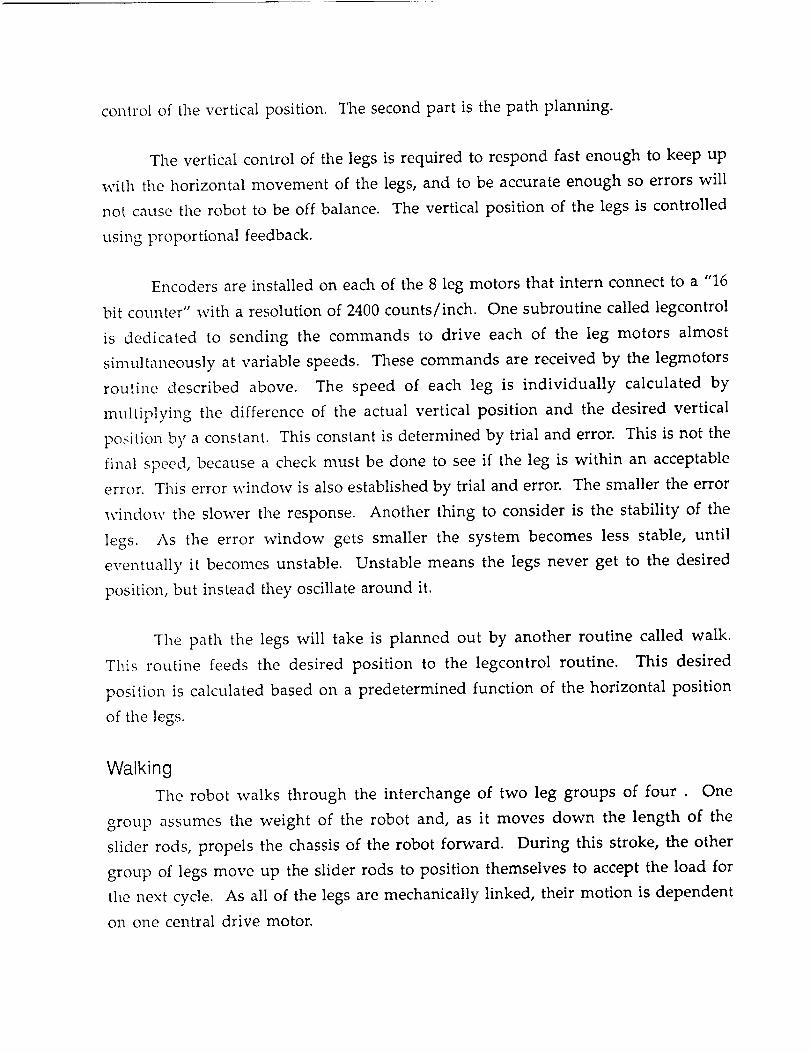
control of the vertical position. The second part is the path planning.
The vertical control of the legs is required to respond fast enough to keep up
with the horizontal movement of the legs, and to be accurate enough so errors will
not cause the robot to be off balance. The vertical position of the legs is controlled
using proportional feedback.
Encoders are installed on each of the 8 leg motors that intern connect to a "16
bit counter" with a resolution of 2400 counts/inch. One subroutine called legcontrol
is dedicated to sending the commands to drive each of the leg motors almost
simultaneously at variable speeds. These commands are received by the legmotors
routine described above. The speed of each leg is individually calculated by
multiplying the difference of the actual vertical position and the desired vertical
position by a constant. This constant is determined by trial and error. This is not the
final speed, because a check must be done to see if the leg is within an acceptable
error. This error window is also established by trial and error. The smaller the error
window the slower the response. Another thing to consider is the stability of the
legs. As the error window gets smaller the system becomes less stable, until
eventually it becomes unstable. Unstable means the legs never get to the desired
position, but instead they oscillate around it.
The path the legs will take is planned out by another routine called walk.
This routine feeds the desired position to the legcontrol routine. This desired
position is calculated based on a predetermined function of the horizontal position
of the legs.
Walking
The robot walks through the interchange of two leg groups of four . One
group assumes the weight of the robot and, as it moves down the length of the
slider rods, propels the chassis of the robot forward. During this stroke, the other
group of legs move up the slider rods to position themselves to accept the load for
the next cycle. As all of the legs are mechanically linked, their motion is dependent
on one central drive motor.
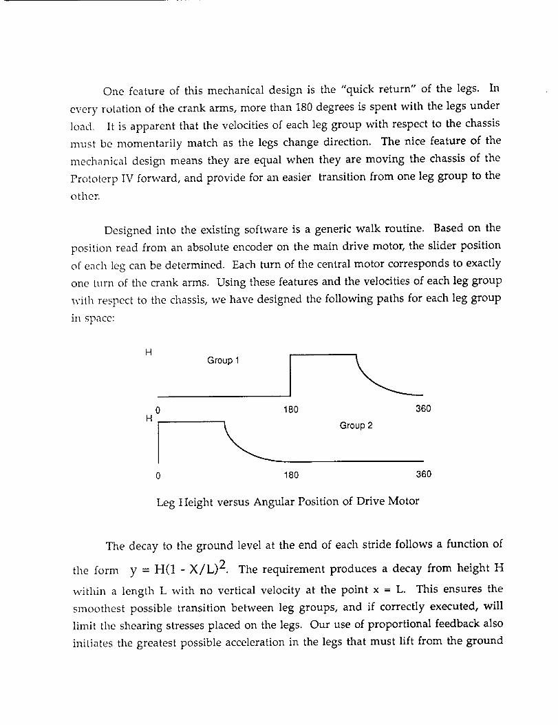
One feature of this mechanical design is the "quick return" of the legs. In
every rotation of the crank arms, more than 180 degrees is spent with the legs under
load. It is apparent that the velocities of each leg group with respect to the chassis
must be momentarily match as the legs change direction. The nice feature of the
mechanical design means they are equal when they are moving the chassis of the
Prototerp IV forward, and provide for an easier transition from one leg group to the
other.
Designed into the existing software is a generic walk routine. Based on the
position read from an absolute encoder on the main drive motor, the slider position
of each leg can be determined. Each turn of the central motor corresponds to exactly
one turn of the crank arms. Using these features and the velocities of each leg group
with respect to the chassis,we have designed the following paths for each leg group
in space:
H
H
Group 1
0 180 360
Group 2
0 180 360
Leg Height versus Angular Position of Drive Motor
The decay to the ground level at the end of each stride follows a function of
the form y = H(1 - X/L) 2. The requirement produces a decay from height H
within a length L with no vertical velocity at the point x = L. This ensures the
smoothest possible transition between leg groups, and if correctly executed, will
limit the shearing stresses placed on the legs. Our use of proportional feedback also
initiates the greatest possible acceleration in the legs that must lift from the ground
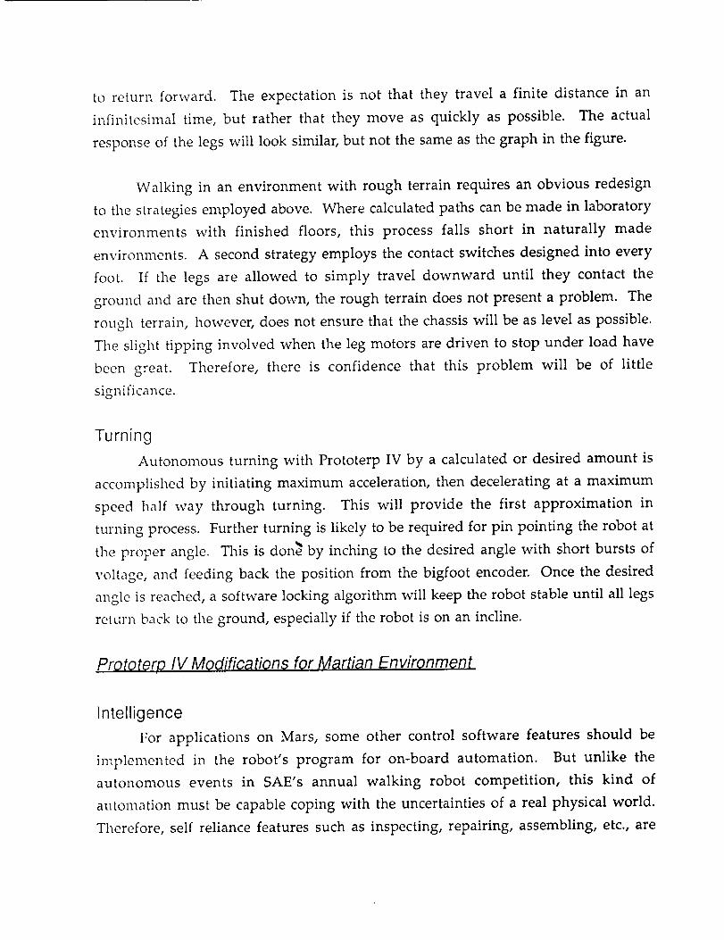
to return forward. The expectation is not that they travel a finite distance in an
infinitesimal time, but rather that they move as quickly as possible. The actual
response of the legs will look similar, but not the sameas the graph in the figure.
Walking in an environment with rough terrain requires an obvious redesign
to the strategies employed above. Where calculated paths can be made in laboratory
environments with finished floors, this process falls short in naturally made
environments. A second strategy employs the contact switches designed into every
foot. If the legs are allowed to simply travel downward until they contact the
ground and are then shut down, the rough terrain does not present a problem. The
rough terrain, however, does not ensure that the chassis will be as level as possible.
The slight tipping involved when the leg motors are driven to stop under load have
been great. Therefore, there is confidence that this problem will be of little
significance.
Turning
Autonomous turning with Prototerp IV by a calculated or desired amount is
accomplished by initiating maximum acceleration, then decelerating at a maximum
speed half way through turning. This will provide the first approximation in
turning process. Further turning is likely to be required for pin pointing the robot at
the proper angle. This is don_ by inching to the desired angle with short bursts of
voltage, and feeding back the position from the bigfoot encoder. Once the desired
angle is reached, a software locking algorithm will keep the robot stable until all legs
return back to the ground, especially if the robot is on an incline.
Prototerp IV Modification,s for Martian Environment
Intelligence
For applications on Mars, some other control software features should be
implemented in the robot's program for on-board automation. But unlike the
autonomous events in SAE's annual walking robot competition, this kind of
automation must be capable coping with the uncertainties of a real physical world.
Therefore, self reliance features such as inspecting, repairing, assembling, etc., are
essential for the robot's survival and longevity in an alien environment.
Furthermore, the minimization of human interaction with advanced space robots
would make exploratory missions on Mars, and other planets, more economically
feasible than manned operations.
When Prototerp IV is placed on Mars to roam and explore, it must, in a sense,
be able to 'think' in order to make decisions and solve problems, and to perform
various unknown tasks autonomously without preprogramming, and without
human intervention. Such high-level control would classify Prototerp IV as a type
artificial intelligence (AI). The decision making process would be done by
manipulating current information with techniques such as advanced on-board
sensory processing, world modeling, and task decomposition. Sensory processing
involves detection of events, recognition of patterns and objects, and correlation
functions of observation versus expectation, also known as expert functions. World
modeling includes modeling of objects and structures, maps of areas, and tables ofstate variables that describe the environment; and task decomposition involves
planning, servo control, and actual decision making based on a hierarchical
structured control system that examines and evaluates the sensory inputs, world
models, and the expert functions in layers of mathematical operations that assign a'decision value' at each level. After several levels of computation of growing
complexity, the robot will make a decision as to what task to perform based on thedecision values at each level. The task most likely to be frequented is collecting and
analyzing data, the primary directive of any exploratory operation; so decisions as to
what data to retain and how to process them are crucial to the successof the mission
Navigation
Navigation of Prototerp IV on the surface of Mars requires a comprehensive
visual system, one perhaps introducing Neural Network integration to reduce
computation and memory overhead. Moving to and around objects in the path will
be determined by size and classified into one of three categories:
a) Objects that can be walked on or over. These pass underneath the chassis
of the robot and/or legs. Important in this determination will be how high
the legs must be raised in order to clear the obstacle.
b) Objects that must be walked around. The fifteen inches of clearance
between the chassis and ground at full extension will not always be enough.
To walk around such an obstacle, the visual system must give the robot the
opportunity to determine the shortest path around the obstacle.
c) Objects that are impassable. Sudden steep grades or cliffs are of utmost
importance. The Prototerp IV will be as helpless as any insect if it falls over
onto its back. The visual system must be able to distinguish these hazards,
giving the robot the reaction time it needs.
Autonomous Performance Tests
In order to maintain proper functioning throughout its mission on Mars,
Prototerp IV would have to continually inspect all electrical and mechanical systems
with a well organized, quick, and efficient systems check routine that would detect
an), mechanical or electrical malfunctions, and glitches within the software itself if
information were somehow lost. The best approach for a systems examination
would be to break down the testing algorithm into several 'trouble shooting' levels,
and to work from outside to inside, so the robot can zoom in on the root of the
problem. This allows the robot to report on any system failure.
Every attempt, of course will be taken to ensure the mechanical integrity of
Prototerp IV's mechanical hardware. However, wear is inevitable and the
performance of the walking machine will have to be monitored. Simple software
routines can be written to monitor the moving parts. The 87C196 microprocessor
allows fo_ real time experimentation. By sending a standard pulse width modulated
signal to a motor, performance becomes a matter of comparing translation in time to
known optimal values. While knowledge of a failing bearing will certainly not
initiate a repair on an unmanned mission, Prototerp IV will have the wherewithal
to compensate and "limp" home to the lander once it senses what is wrong.
Electronic hardware may also be tested by the microprocessor. Simple
memory accessing can confirm component integrity. Mechanical switches may also
be tested. Assuming that multiple system failure is not likely, the Prototerp IV has
the ability to input data from several sources to ferret out inferior data. For
example, at full extension, all contact switches will close and the absolute encoders
will report a standard data pattern. The robot can confirm switch performance by
assuming this stance, and testing each switch in succession.
The robot will also come equipped with electronic backup systems. A simple
design of an microprocessor hierarchy can power only one system at a time.
Redundancy and conflict can be eliminated by designing a master microprocessor. A
processor as simple as an 8085 can be given the ability to power up and down the
more powerful 87C196 processors and other memory components thereby allowing
for some electronic failure and still have operation.
All robot controls must be both flexible and permanent. Different or
unexpected situations will require some ingenuity and off the cuff programming
from Earth, and the systems must be designed to handle last minute changes. The
87C196comes equipped with autonomous programming ability that can be utilized.
With the 8085 master processor system, the 87C196's will look to download any of a
variety of operating systems. These systems may be placed on magnetic sources
while others will be permanently affixed on proper ROM. This allows for
continuous redesign of software without the hazard of losing at least the basic
functioning abilities
Leg Redesign
Perhaps the most inefficient motion the Prototerp IV will undergo is the
transition from walking to turning and back. Navigation of any slalom means an
endless number of transitions to make slight modifications to direction, effectively
bringing the robot to a halt. While the current central Bigfoot design is effective for
large angular turns, its inefficiency grows tremendously for small modifications.
The possible redesign of the slider rod assemblies and attachments to the
chassis of the robot may give Prototerp IV exactly what it needs. By giving these rod
assemblies small horizontal translation ability, the computer may introduce a radius
of curvature to its path, and avoid obstacles that would have partially obstructed its
path. Signs of the same design strategies are already seen in the automotive
industry, where the back wheels of cars turn slightly. This tightens the turning

radius and improves performance. In this design, it means much less transition
from legs to Bigfoot. It makes for a faster robot.
The independent nature of the two leg groups would still have to be
maintained, but from a controls standpoint, the implementation is simple.
Mechanically, this design seemsplausible also. One would have to design a system
with a potential energy minimum at zero degrees deflection.
Conclusion
It is evident that no set of algoriths developed here on Earth can ever hope to
achieve systematic walking on the surface of Mars. Regardless, the methods
developed in this preliminary exploration into possible walking starategies, if ever
expanded, can form a basis to make operation possible. The surface of Mars is not
uniform, nor is continuous from one region to the next. Software control of any
robot, therefore, cannot be comprehensive. The robot must be in constant contact
with operators on Earth, and, though it will not learn to adapt to the conditions of
that dynamic planet, the human beings behind its operation will. It is those
engineers that wilI finalIy determine how well Prototerp IV will operate on Mars.
Those of us in Software like it that way.
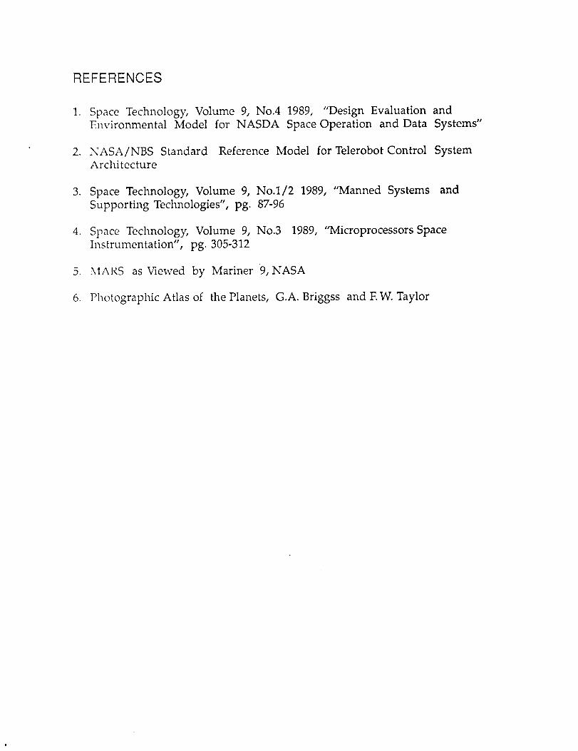
REFERENCES
1. Space Technology, Volume 9, No.4 1989, "Design Evaluation and
Environmental Model for NASDA Space Operation and Data Systems"
2. NASA/NBS Standard Reference Model for Telerobot Control System
Architecture
3. Space Technology, Volume 9, No.1/2 1989, "Manned Systems and
Supporting Technologies", pg. 87-96
4. Space Technology, Volume 9, No.3 1989, "Microprocessors Space
Instrumentation", pg. 305-312
5. MARS as Viewed by Mariner 9, NASA
6. Photographic Atlas of the Planets, G.A. Briggss and EW. Taylor

APPENDIX F:
MARTIAN CONSIDERATIONS
DESIGN ALTERATIONS OF PROTOTERP IV FOR MARS
EXPLORATION
CHASSIS AND BIGFOOT GROUP
SPRING, 1990
GROUP MEMBERS:
DARREN LEAP
LISA STEEN
TOM NAVE
TIM CONDON
Abstract
There are two major advantages that walking robots have over standard robots, such as
those possessing tracks or wheels. Legged locomotion provides a greater versatility to
handle any given terrain, and walking machines can theoretically travel in places
inaccessible to other machines. One promising application for walking machines is nuclear
waste clean-up and removal. Another is in space exploration. Since Mars possesses very
uneven and diverse terrain, a natural application would be a walking Mars rover. The
feasibility of adapting the University of Maryland's walking robot, Prototerp IV, to a Mars
rover is examined. In particular, issues relating to Prototerp's chassis and centrally located
turning mechanism, "Bigfoot" are addressed.
Iotroduction
In the future, machines capable of autonomous operation through the use of artificial
intelligence will play a crucial role in space exploration. NASA's Automation and Robotics
Technology Development Program has stated that the "goal for intelligent automation is to
increase robustness" and create machines that are able to "cope with a greater variety of
circumstances through increased sensing "1. A major problem in developing versatile
walking robots and autonomous vehicles in general, is the limitation imposed by the
sensors 2. As technology develops and improves sensor capabilities, walking robots will
become more sophisticated and widely used.
The Prototerp IV design possesses some versatile features including the independent
control of each leg's height, and variable stride capabilities. However, Prototerp's Bigfoot
assembly which enables the robot to rotate and change direction, limits the possible terrain
to fiat and level surfaces. Design modifications are proposed to enable the Bigfoot assembly
to handle uneven and inclined terrain. The ultimate goal is to enable the robot to change
direction in any area that the robot may travel.
Another important change that must be made, is the reduction of the Prototerp's
weight. The Prototerp exceeds 440 Kg which is unacceptable for space applications. The
main chassis and Bigfoot material, aluminum, must be changed to a material with a higher

strength-to-weightratio. Also, a protectivecovering must be designed to protect the robot's
electrical and mechanical components.
The general philosophy of the proposed design modifications was to increase the
capability of adaptation to a Mars environment, without unnecessarily increasing the
complexity of the overall system. Some important design criterion have been stated in
"Issues and Options for a Mars Rover"3.They are stated as follows:
I. Minimize delays caused by obstacles in walker's path.
2. Maximize kinds of terrain the rover can handle.
3. Minimize the number of stops needed to request help from Earth.
4. Minimize cost, weight and power.
5. Maximize redundancy and backup modes.
To better understand the needed capabilities of the design, the Martian environmenl is
• examined in more detail.
Martian Environment
The Martian environment poses many challenges for an autonomous walking robot.
A Mars rover must be able to receive information from its surroundings and make changes
accordingly. To prepare Prototerp IV for a Mars mission, every possible situation must be
taken into account and the robot must be given the capability to adapt.
Exploration of the possibilities for a Mars rover was motivated by the irregular and
varied types of surface conditions present on the planet. Of major concern are the rocky
fields which cover nearly half of the planet's surface. Boulders of up to eight meters tall
have also been reported 4. Just as treacherous to a walking machine are the desert-like
areas having sand dunes composed of fine panicles. Mountains, volcanoes, crusty surfaced
craters, and ice-covered poles are also present.
"v%ather conditions pose additional problems. Maximum steady winds of up to 70
m/s have been predicted to occur on Mar's surface 5. At these speeds, fine sand particles can
be picked up from the surface and create sand and dust storms 6. When this occurs the robot
may be isolated from earth control.
There are also several factors that would help a robots performance. There is no
water in the liquid state, thereforethere is no rain. The atmosphereis composedof CO2, N,
Ar, and other inert gases,havingminor constituents of water vapor,dust,CO,O2, and03.
Thesewould not poseproblemsto a robust rover. Finally, the gravity on mars is only 38%
of earth's,which wouldhelp reducethe powerrequirements,and the weight of the robot.
Changes to Bigfoot
The present Bigfoot design has square aluminum tubing mounted to a central
bearing which is geared to the Bigfoot drive motor as shown in Figs. 1.a. and b. Connected
underneath the channel are four contact pegs. When the robot switches from the walking to
the turning mode, its main legs telescope up and the robot comes to rest on the contact pegs.
The bearing and motor assembly could adapt well with a Mars rover, but the channel and
legs comprising the foot must be changed to accommodate inclined and uneven areas.
One suggested solution to the problem was through the use of constrained rods which
could hug the particular contour and still maintain a level robot frame (Fig. 2). This design
creates many problems. It does not incorporate the possibility of walking on a grade and it
has the potential for instability on certain types of terrain. The other concerns are the
difficulty in fabrication and the weight of the assembly.
Three other modifications are suggested. The first is to have the foot made up of
many flexible Joints connecting the contact pegs to the aluminum channel (Figs. 3.a. and b.).
The second suggestion is similar to mount circular housing assemblies on to a disc. The
contact pegs could then be spring loaded into the housings (Figs. 4.a. and b.). Both designs
have limits on the types of terrain they can handle. Finally, the design could incorporate a
leg assembly similar to that designed by Stephen Bartholet for Odetics, Inc. 7.
The first generation of the design incorporates a vertical actuator mechanism shown
in numbers 32 to 34 in Figure 5. This mechanism allows the leg to fold out to support the
robot during turning and retract when the robot is in the walking mode. Several major
advantages are apparent. The structure provides the best possible stability of the robot
under rough and inclined terrain conditions, and the assembly can be made very compact
due to its folding ability. The inventor improved on this first design by incorporating a
"dogleg" on member 17 as shown in Figure 68 . This allows the legs to fold even more
compactly against the robots center. Also shown is a horizontal leg drive, numbers 50-55.
This horizontal actuator system could act as a backup leg drive unit. By making member 22
in Figure 6 spring loaded into member 23 the terrain handling capabilities could be further
increased. The drive gear, 41, could be meshed to the present Bigfoot motor through an
electric solenoid and this would negate the use of a separate motor for the vertical actuator
(40 in Figure 6).
This leg system has been tested and proven to be capable of walking on a 30 degree
grade 9. Due to this and the above mentioned advantages, it is the last design that is
recommended. An analysis would still be needed to size the components, determine the
number of Bigfoot legs required, etc. A working drawing, including the entire robot
assembly, should also be created to ensure that the Bigfoot's legs could operated under the
constraints of the main drive legs.
Material selection
An important consideration for space application is weight. Prototerp IV's structure
is made almost entirely of aluminum components. Aluminum was chosen for its strength,
ease of machinability, cost and availability. As stated previously, its weight requires that
we limit its use as much as possible. In areas where we need to use metal, such as the slider
rods, bolts, etc., alloys with higher strength-to-weight ratios such as Titanium-Al alloys
should be considered 10. For the support frame and other areas, however, a good choice
would be carbon fiber composites.
Carbon fiber composites have a very high strength-to-weight ratio, excellent fatigue
strength and are easily formed by machining and molding. As seen in Figure 7, the strength
of this material is independent of temperature from 0 ° C to well above 1500 ° C ,which
exceeds any temperatures which will be encountered on Mars 11. Due to the geometry of the
carbon fiber matrix, crack propagation is retarded so that if the robot were to fall, little
damage to the frame would result. These materials cannot be welded together, but can be
fastened mechanically with bolts, rivets or epoxy. Care must be taken when fastening the
composite. If bolts are used, drilled holes should be used rather than molding the holes into
the material because during the molding process, the fibers will deform around the hole and
cause a weak Joint. It is also recommended that the holes be reinforced with composite
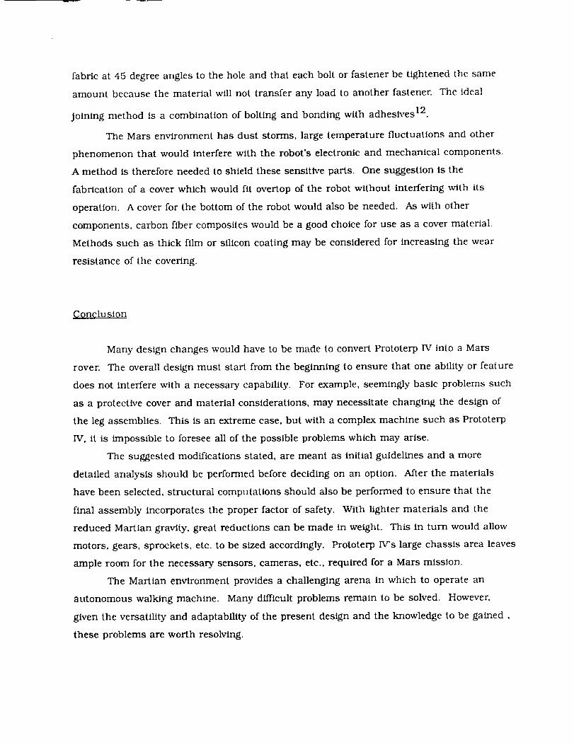
fabric at 45 degreeanglesto the holeand that eachbolt or fastener be tightened the same
amount because the material will not transfer any load to another fastener. The ideal
Joining method is a combination of bolting and bonding with adheslves 12.
The Mars environment has dust storms, large temperature fluctuations and other
phenomenon that would interfere with the robot's electronic and mechanical components.
A method is therefore needed to shield these sensitive parts. One suggestion is the
fabrication of a cover which would fit overtop of the robot without interfering with its
operation. A cover for the bottom of the robot would also be needed. As with other
components, carbon fiber composites would be a good choice for use as a cover material.
Methods such as thick film or silicon coating may be considered for increasing the wear
resistance of the covering.
Conclusion
Many design changes would have to be made to convert Prototerp IV into a Mars
rover. The overall design must start from the beginning to ensure that one ability or feature
does not interfere with a necessary capability. For example, seemingly basic problems such
as a protective cover and material considerations, may necessitate changing the design of
the leg assemblies. This is an extreme case, but with a complex machine such as Prototerp
IV, it is impossible to foresee all of the possible problems which may arise.
The suggested modifications stated, are meant as initial guidelines and a more
detailed analysis should be performed before deciding on an option. After the materials
have been selected, structural computations should also be performed to ensure that the
final assembly incorporates the proper factor of safety. With lighter materials and the
reduced Martian gravity, great reductions can be made in weight. This in turn would allow
motors, gears, sprockets, etc. to be sized accordingly. Prototerp IV's large chassis area leaves
ample room for the necessary sensors, cameras, etc., required for a Mars mission.
The Martian environment provides a challenging arena in which to operate an
autonomous walking machine. Many difficult problems remain to be solved. However,
given the versatility and adaptability of the present design and the knowledge to be gained,
these problems are worth resolving.
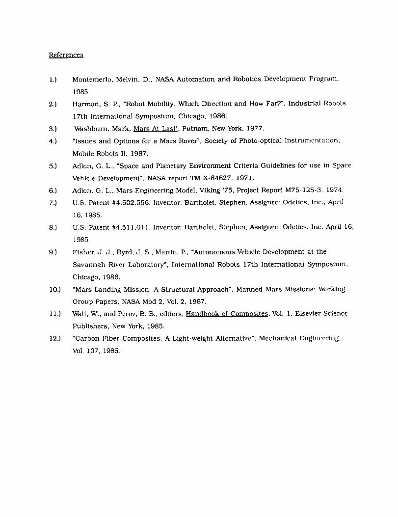
References
13
2.1
3.)
4.)
5.)
6.)
7.)
8.)
9.)
10.)
11.)
12.)
Montemerlo, Melvin, D., NASA Automation and Robotics Development Program,
1985.
Harmon, S. P., "Robot Mobility, Which Direction and How Far?', Industrial Robots
17th International Symposium, Chicago, 1986.
Washburn, Mark, Mar_ At Last!, Putnam, NewYork, 1977.
"Issues and Options for a Mars Rover", Society of Photo-optical Instrumentation,
Mobile Robots II, 1987.
Adlon, G. L., "Space and Planetary Environment Criteria Guidelines for use in Space
Vehicle Development", NASA report TM X-64627. 1971.
Adlon, G. L., Mars Engineering Model, Viking '75, Project Report M75-125-3, 1974,
U.S. Patent #4,502,556, Inventor: Bartholet, Stephen, Assignee: Odetics, Inc., April
16, 1985.
U.S. Patent #4,511,01 I, Inventor: Bartholet, Stephen, Assignee: Odetics, Inc. April 16,
1985.
Fisher, J. J., Byrd, J. S., Martin, P., "Autonomous Vehicle Development at the
Savannah River Laboratory", International Robots 17th International Symposium,
Chicago, 1986.
"Mars Landing Mission: A Structural Approach", Manned Mars Missions: Working
Group Papers, NASA Mod 2, Vol. 2, 1987.
Watt, W., and Perov, B. B., editors, Handbook of Composites, Vol. 1, Elsevier Science
Publishers, New York, 1985.
"Carbon Fiber Composites, A Light-weight Alternative", Mechanical Engineering,
Vol. 107, 1985.
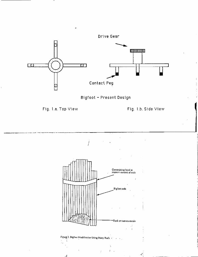
I _)
Fig. 1.a.Top View
(') I
Drive Gear
I
Contact Peg
Bigfoot - Present Design
Fig. 1.b.Side View
C.//ons_alning band tomaJnt,',_ control of rods
Bigfoot rods
Rock or uneven terrain
1
Figure. 2. Bigfoot Modification Using Many Rods •
o,i "/'
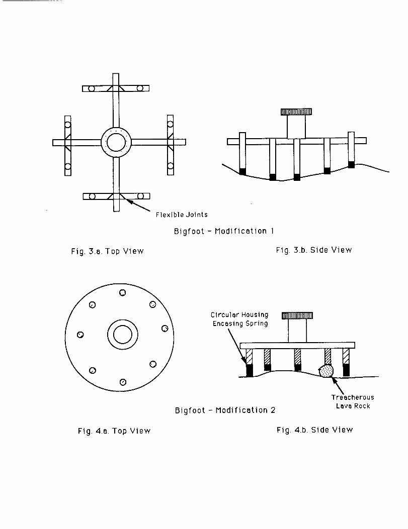
I C} / \ C} I
I i ¸
m
uu,
Fig. 3.a. Top View
J
/i
\!
Flexible Joints
Bigfoot- Modification I
Fig. 3.b. Side View
Circular Housing
Encasing Spring
Bigfoot- Modification 2
II
Treacherous
Lava Rock
Fig. 4.a. Top View Fig. 4.b. Side View
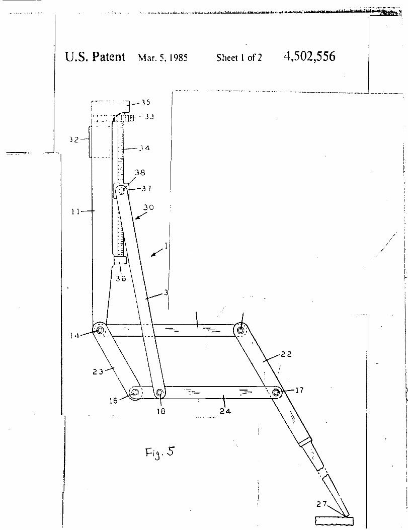
U.S. Patent Ma_.5, 1985 Sheet1of2 '1,502,556
],.1.j
18
18 24
.Fi
..f
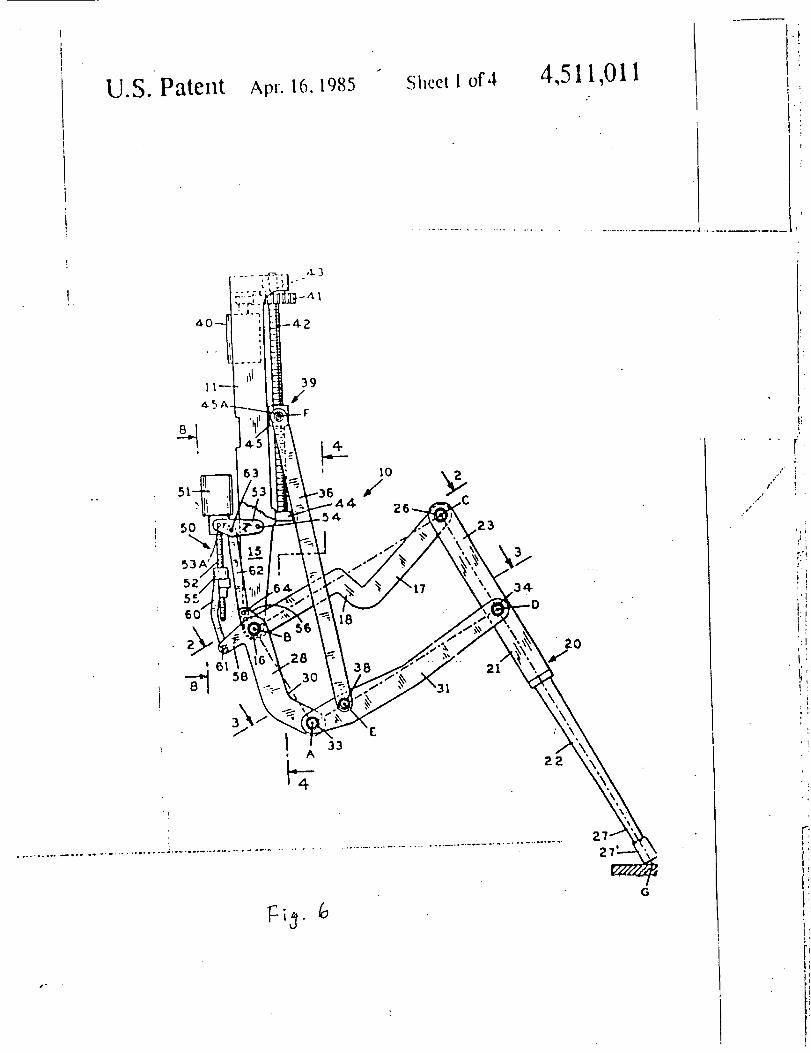
U.S. Patent Apr. 16, 1985 Sheet I of 4 4,511,011
2
39
/F
53
52'
!
!
18
33
/oG
f
(
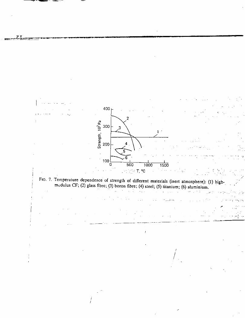
I
............. ,.j
. . .
400 -
300
d
"_ 200
t_6 _ _ .. .100 i
0 500 1000
...... •': T, °C
.
/
J I1500
°.
,.r I- " --
FIG. 7. Temperature dependence of strength of different materials (inert atmosphere): (1) high - :" ""modulus CF; (2) glass fibre; (3) boron fibre; (4) steel; (5) titanium; (6) aluminium_ .
t/
/
I'
!
ADAPTATIONS OF PROTOTERP IV WALKING ROBOT
FOR MARS EXPLORATION
(LEG GROUP)
ENME 408 Walking Robot
University of Maryland, College Park
Prepared By: Jim Bielec
David HartsigManuel Oliva
Bob Olsen
Bob Rose
INTRODUCTION
The Viking missions of the 1970's gave the world a direct view of Mars from its surface. Since
that time a Mars Rover/Sample Return Mission has been called for. One of the unique aspects
of this mission is a Mars rover which not only will collect data and samples, as did Viking, but also
have the added flexibility of mobility. Design ideas for a rover include simple four wheeled vehicles
which are easy to build and control, but cannot traverse many different terrains. Caterpillar like
wheeled vehicles are more stable than the four wheeled version, yet can not roll over obstacles of
considerable height. According to "Issues and Options for a Mars Rover "6, the best design for a
Mars rover would be a multi-legged walking robot. Such a robot would be able to travel over
many terrains and thus be able to explore a large part of the surface of Mars. This paper deals
with the adaptation of the PROTOTERP IV for service as a Mars rover.

Accordingto a NASA Jet PropulsionLaboratorybriefing, an idealMars explorationrover
shouldweighabout1,700pounds,travelat least0.6milesa dayover a threeyearperiod,and be
able to climb a 60% smoothgradeor a 35% loosesandand gravelgrade_.In addition,an
assumptionwasmadebythe authorsthat theroverwouldencountersuddendropsof no morethan
17inchesand travelon terrainsimilarto Figure 1.2
Figure1. Thenearfieldat theViking2 landingsite. A trough filled with fine-grainedsediment runs from the upper left to the lower right. Most of the rocks are deeply pitted,as a result of either a primary vesicularity or etching by the wind. The more massive rock
to the upper right is about 1 m across. (Viking lander 2 event no. 21A024)
oW, G_NAL PAGE IS
OF pOOR QUALIT_
Such requirements could be met by the PROTOTERP IV if the legs were slightly modified.
The advantage of the PROTOTERP IV compared to a wheeled or tractor design is it's ability to
vary leg extension and stride length under different surface conditions. This allows the rover to
remain horizontal on varied surfaces and to step up to or over most obstacles. Although a
wheeled rover would be faster and simpler to build, it's maneuverability and range would be
decreased, due to craters and rocks, and thus defeat the purpose of the rover, which is to travel
over many varied surfaces z.
Some of the modifications needed to adapt the PROTOTERP IV include, larger motors, seals
to keep dust out, a new foot pad design and material and lubrication considerations. Each
modification is discussed below.
Because the weight of the rover is only 1,700 earth pounds which is about 600 pounds on
Mars, each leg will only have to carry 150 pounds with four legs on the ground at all times. The
tubes and bearings used in PROTOTERP IV are capable of this load but the worm gear and
especially the motor would need to be increased in size. Based on practical experience with
PROTOTERP IV, the worm gears would need to be twice as large and the motor four times as
powerful.
The Mars atmosphere can be very dusty with dust storms quite common s. Dust could be very
damaging if it reaches the motors, gears, bearings or screw jack. Sealed bearings should be used
because they are self contained and do not require servicing. The motors and worm gears should
be completely enclosed, preferably within the outer tubing of the leg. With the motors and gears
completely sealed on the top of the outer tube, the only manner in which dust could enter the
screw jack is where the inner tube slides in and out of the outer tube. A seal at this point would
therefore eliminate any dust from entering.
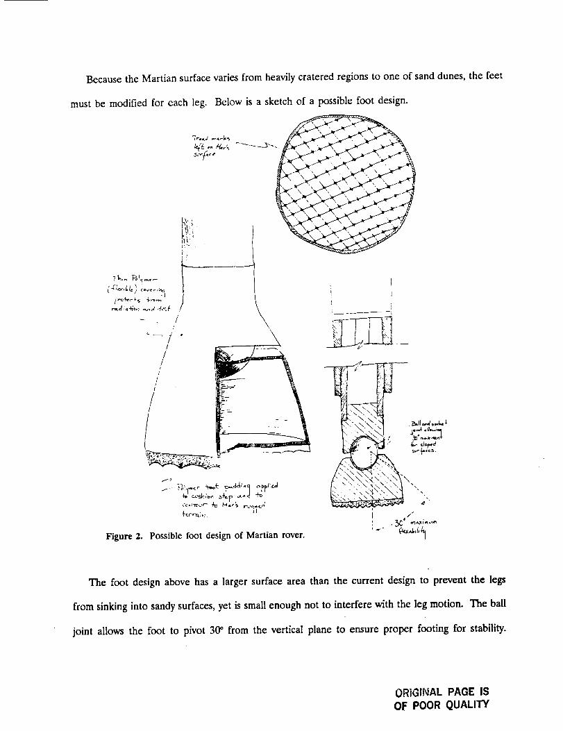
Because the Martian surface varies from heavily cratered regions to one of sand dunes, the feet
must be modified for each leg.
/
/s
1
/
//
f
Below is a sketch of a possible foot design.
_r i
J_,r_t • d
\
_'trr'a.i _7
Figure 2. Possible foot design of Martian rover.
1
?
N "
The foot design above has a larger surface area than the current design to prevent the legs
from sinking into sandy surfaces, yet is small enough not to interfere with the leg motion. The ball
joint allows the foot to pivot 3& from the vertical plane to ensure proper footing for stability.
ORIGINAL PAGE ISOF POOR QUALITY
The polymer pad gives traction and allows the bottom surface to contour to the shape of the rough
terrain. A rubber cover is used to prevent dust from entering the ball joint and the bottom of the
inner tube.
The materials for such a mission need to be strong, light weight and able to withstand sudden
temperature changes between -140_C and 68°C 4. While both aluminum and titanium are light and
strong, aluminum can be hard worked, is easy to machine, and resists chemical corrosion better
than titanium. Another requirement of the material is its reflectability of the sun to reduce heat
gain. This is important because the Mars sun can be strong when there are no dust storms.
Aluminum also satisfies this requirement. High carbon steel used in the bearings and screw jack
will not rust because of the lack of moisture in the Mars atmosphere. Therefore, the same
materials used in PROTOTERP IV could be used in the Mars application.
Lubrication for the gears and screw jack would need to withstand long duty life and large
temperature changes. Synthetic lubricants are the best choice since they have a wide service
temperature range. This means they maintain good flow characteristics at low temperatures and
are stable at high temperatures. It is, however, important that the lubrication and seals are
properly matched to ensure compatibility s.
One major modification which would be required is the addition of an "escape device", in
order to prevent the rover from becoming trapped on the hazardous martian surface. For example
if the rover were to fall over or get trapped in a deep hole, a mechanical arm could be used to
pull the rover out of trouble. This same arm could obviously be used to collect samples from the
surface. It is important that the design of the arm take into consideration it's possible use as a
ninth leg. Other possible design options would be the use of air bags, stabilizing struts or even
winches and grappling hooks _. For extreme situations, breakaway mechanisms such as the foot pads
could be sacrificed to allow the robot to break free. Although this would hinder the robots ability
to maneuver,it wouldallow the missionto continue.
Becausethecurrentdesignof thePROTOTERPIV offershighmaneuverability,it is possible
to explorea largeextentof the Mars' surface.As seen,modificationswouldbe neededin order
to meet the specificenvironmentof Mars. Becausethe modificationsdo not affect the basic
operationof the rover,anyexperiencegainedby PROTOTERPIV couldhavedirect application
in understandinghow futureMarsmissionscouldbe successfullyplannedand performed.
REFERENCES
1 "NASA Briefs Contractors on Mars Rover/Sample Mission",
by Michael A. Dornhelm, Aviation Week & Space
Technology, April 6, 1987, pp 22(2).
2 "The Surface of Mars", by Micheal H. Carr,
New Haven and London, Yale University Press, 1982.
3 "Advances in Space ResearchfI'he Mars Reference
Atmosphere", Edited by A. Kliore, Volume 2, Number 2,1982.
4 The Encyclopedia Americana, Grolier Incorporated 1989.
5 "Lubrication Fundamentals", J George Wills, Marcel Dekker
Inc., New York and Basel, 1980.
6 "Issues and Options for a Mars Rover", Martin Marietta
Space Systems Company, page 169.
7 "Hazard Avoidance for a Mars rover", Andrew J Spiessback,
Martin Marietta Space Systems, pages 77-79.
8 "Surface Models of Mars", NASA Space Vehicle Design
Criteria (Environment), NASA 1975.