Embed Size (px)
Citation preview
University of Minnesota Minnesota Nano Center
Standard Operating Procedure
1
Equipment Name: CHA Evaporator
Badger Name: ebevap-cha Revision Number: 14
Model: SEC 600 Revisionist: L. von Dissen
Location: PAN Bay 3 Date: 09/19/2018
1 Description
The CHA Evaporator is a single source electron beam evaporator. It has a lift-off
fixture and a planetary fixture for 4” wafers. It can run up to six different
materials in a run. The lift-off fixture holds 9 wafers, and the planetary fixture
holds 6 wafers each; since there are 3 planetary fixtures that can be used, a total of
18 wafers can be run at one time.
Note: For users that desire to run 6” wafers, MNC has a fixture available
which can accommodate up to three 6” wafers at once. Ask appropriate
MNC staff for details.
2 Safety a. Use the dark tinted, welder's glass provided when looking directly at the beam if it
is too bright, or alternatively you can use tinted safety glasses.
b. Take care when loading wafers and crucibles. Use a step stool if needed.
c. The crucibles may be hot when unloading. Be careful when handling.
3 Restrictions/Requirements
a. DO NOT leave the system during deposition for more than 10 minutes at a time
and ONLY after the beam is verified to be in the pocket.
b. During a FIRE or lab GAS alarm press F12 on the SEIMENS computer to abort
a run if the system is running. You can also press the STOP button on the Inficon
computer to stop the process. The red EMO button should only be pressed if
there is obvious danger such as fire, smoke, or a water leak.
c. Materials are restricted to those listed on the CHA Material Parameters
Sheet located in the CHA Log Book. See Staff for approval of other
materials.
d. The first 3 pockets are dedicated to Aluminum, Cobalt, and Gold.
e. Do not put scotch tape in the CHA! Only use “Kapton” (polyimide) tape
4 Required Facilities
a. Compressed air 80-90 psi
b. Process water
c. Nitrogen gas
d. Electrical 208/240 VAC
e. House Exhaust
University of Minnesota Minnesota Nano Center
Standard Operating Procedure
2
5 Definitions
a. INFICON (IC6): The computer where recipes are written and stored.
b. SEIMENS: The computer that is the operator interface. It is controlled by the
keyboard and mouse pad as well as the touch panel surrounding the monitor. It
has a picture of the bell jar as well as all the fixturing and major valves within the
system. Buttons that are displayed are used to operate the system.
c. Gun: This refers to the copper hearth that holds several metals to be evaporated.
d. Crucible: This is a name used to describe each “gun” position (1 through 6).
e. Pocket: This is another name used to describe each “gun” position (1 through 6).
f. Crystal / QCM: This is the deposition monitoring crystal (QCM: Quartz Crystal
Microbalance) which is used to monitor the deposition rate and thickness of the
depositing film.
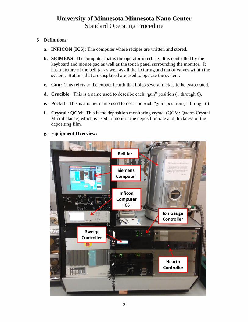
g. Equipment Overview:
Siemens
Computer
Inficon
Computer IC6
Ion Gauge
Controller
Bell Jar
Sweep Controller
Hearth
Controller
University of Minnesota Minnesota Nano Center
Standard Operating Procedure
3
6 Setup
a. Enable the CHA with the Badger system.
7 Operating Instructions
a. VENT THE CHA
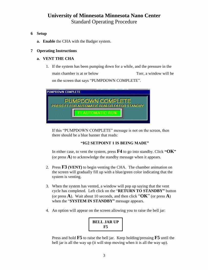
1. If the system has been pumping down for a while, and the pressure in the
main chamber is at or below Torr, a window will be
on the screen that says “PUMPDOWN COMPLETE”.
If this “PUMPDOWN COMPLETE” message is not on the screen, then
there should be a blue banner that reads:
“IG2 SETPOINT 1 IS BEING MADE”
In either case, to vent the system, press F4 to go into standby. Click “OK”
(or press A) to acknowledge the standby message when it appears.
2. Press F3 (VENT) to begin venting the CHA. The chamber animation on
the screen will gradually fill up with a blue/green color indicating that the
system is venting.
3. When the system has vented, a window will pop up saying that the vent
cycle has completed. Left click on the “RETURN TO STANDBY” button
(or press A). Wait about 10 seconds, and then click “OK” (or press A)
when the “SYSTEM IN STANDBY” message appears.
4. An option will appear on the screen allowing you to raise the bell jar:
Press and hold F5 to raise the bell jar. Keep holding/pressing F5 until the
bell jar is all the way up (it will stop moving when it is all the way up).
BELL JAR UP
F5
University of Minnesota Minnesota Nano Center
Standard Operating Procedure
4
5. When the bell jar has moved up, the “BELL JAR DOWN” option pops up,
which will be used after you are finished loading/unloading the chamber.
b. LOAD SAMPLES
1. With the bell jar open, load wafers onto the LIFT-OFF dome. Secure the
wafers / holders to the dome with the clips. Fill any empty spots on the
dome with samples holders. If using the PLANETARY fixture, the
PLANETS should be loaded before hanging them on the planet pole fixture,
and the load should be evenly distributed around the planet (i.e. equal
spacing and weight distribution of wafers if possible).
c. LOAD SOURCE MATERIAL – POCKETS
1. The CHA has 6 pockets in the gun. The first 3 pockets have been dedicated
to particular materials. These dedicated pockets should always have the
dedicated materials in them. Verify that those dedicated materials are in
the CHA if you are going to use them during your run. If the aluminum or
chromium sources look low, there should be aluminum and chromium
pellets in the cabinet to the left of the bell jar in their own labeled drawers.
Place a couple of pellets in the appropriate pocket if needed (do not overfill
beyond the height of the pocket). Contact an MNC staff member if you
need help refilling or replacing any material.
Pocket 1: Solid Aluminum (no liner)
Pocket 2: Cobalt (no liner)
Pocket 3: Gold (Tungsten liner with two buttons underneath)
Pocket 4-6: Open for use, and can be loaded with any of the allowed
materials.
2. Press F7 to open the scissor shutter in order to access the various pockets
and metal sources in the hearth.
3. Every user must weigh the gold source (and the two buttons that normally
lay underneath this gold source) before any run is performed. Press F6 to
rotate the gun to a different pocket. A window will pop up with different
pocket numbers. Since the gold source is dedicated in pocket 3, select
pocket 3 by pressing the number 3 on the keyboard/keypad or by clicking on
“Pocket 3” on the Siemens computer screen using the mouse/track-pad. The
gun will slowly rotate to the pocket you selected.
BELL JAR DOWN
F4
University of Minnesota Minnesota Nano Center
Standard Operating Procedure
5
4. Turn on the scale located to the left of the bell jar. Remove the gold source
(and the two buttons that are underneath the gold source) from pocket 3 and
place it on the scale. Record the combined weight of the gold source and
the two buttons in the CHA log book. Place the two buttons back in to the
center of pocket 3. Place the gold source back on top of the buttons in the
center of pocket 3. If you plan to use platinum or palladium, weigh those
sources as well and then record those weights in the log book (record the
combined weight of the metal source and the two buttons).
5. If you plan to load or evaporate materials from other pockets in the gun,
select those pockets on the Siemens computer screen and physically load
them with the desired materials as needed. Left click on DONE (or press A)
when finished loading all desired pockets.
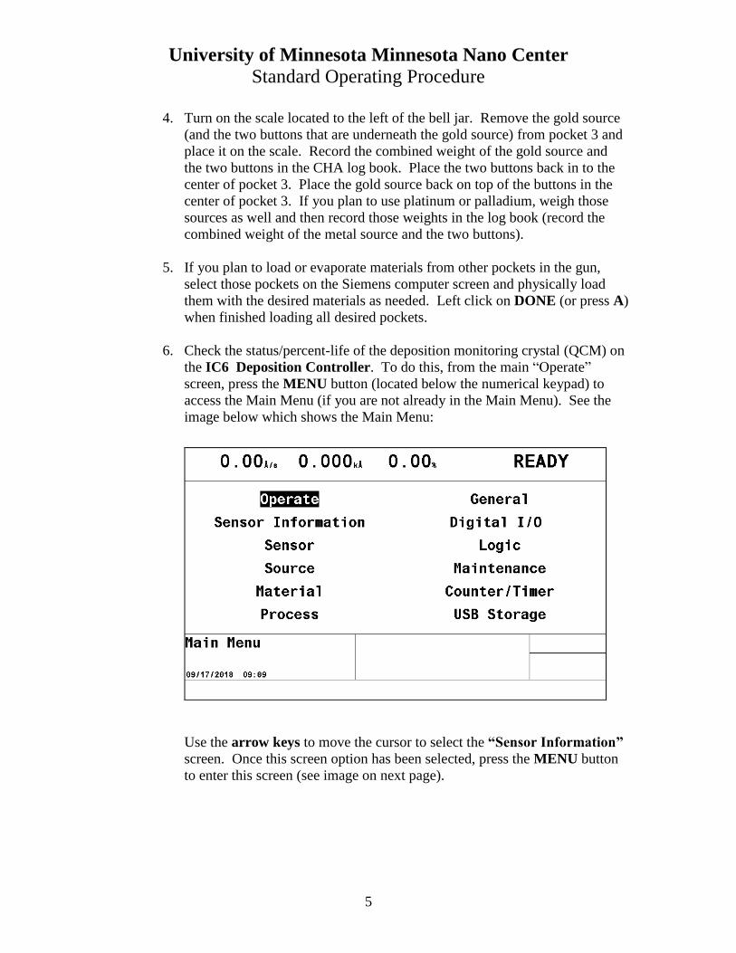
6. Check the status/percent-life of the deposition monitoring crystal (QCM) on
the IC6 Deposition Controller. To do this, from the main “Operate”
screen, press the MENU button (located below the numerical keypad) to
access the Main Menu (if you are not already in the Main Menu). See the
image below which shows the Main Menu:
Use the arrow keys to move the cursor to select the “Sensor Information”
screen. Once this screen option has been selected, press the MENU button
to enter this screen (see image on next page).
University of Minnesota Minnesota Nano Center
Standard Operating Procedure
6
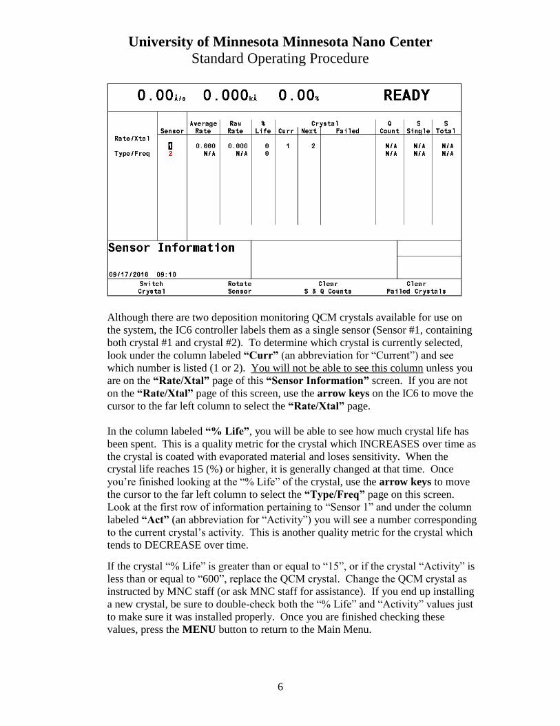
Although there are two deposition monitoring QCM crystals available for use on
the system, the IC6 controller labels them as a single sensor (Sensor #1, containing
both crystal #1 and crystal #2). To determine which crystal is currently selected,
look under the column labeled “Curr” (an abbreviation for “Current”) and see
which number is listed (1 or 2). You will not be able to see this column unless you
are on the “Rate/Xtal” page of this “Sensor Information” screen. If you are not
on the “Rate/Xtal” page of this screen, use the arrow keys on the IC6 to move the
cursor to the far left column to select the “Rate/Xtal” page.
In the column labeled “% Life”, you will be able to see how much crystal life has
been spent. This is a quality metric for the crystal which INCREASES over time as
the crystal is coated with evaporated material and loses sensitivity. When the
crystal life reaches 15 (%) or higher, it is generally changed at that time. Once
you’re finished looking at the “% Life” of the crystal, use the arrow keys to move
the cursor to the far left column to select the “Type/Freq” page on this screen.
Look at the first row of information pertaining to “Sensor 1” and under the column
labeled “Act” (an abbreviation for “Activity”) you will see a number corresponding
to the current crystal’s activity. This is another quality metric for the crystal which
tends to DECREASE over time.
If the crystal “% Life” is greater than or equal to “15”, or if the crystal “Activity” is
less than or equal to “600”, replace the QCM crystal. Change the QCM crystal as
instructed by MNC staff (or ask MNC staff for assistance). If you end up installing
a new crystal, be sure to double-check both the “% Life” and “Activity” values just
to make sure it was installed properly. Once you are finished checking these
values, press the MENU button to return to the Main Menu.
University of Minnesota Minnesota Nano Center
Standard Operating Procedure
7
7. Look in the bottom mirror of the periscope assembly to make sure that the
pocket in the gun is visible in the reflection off the mirror. You want to do
this to ensure that you can see the pocket with this mirror before closing the
chamber and pumping down as the pocket visibility is critical once the e-
beam is turned on.
8. Check the chamber’s internal hardware for peeling/flaking metal and inform
MNC staff if there is a significant amount of build-up. The most important
areas to check for metal peeling/flaking are the bottom of the scissor shutter
and the area surrounding the pockets themselves. If the shutters or pockets
are peeling/flaking, ask MNC staff for assistance so the shutters can be
changed out and/or so the pockets can be quickly cleaned prior to pumping
the system down. Peeling/flaking metal can contaminate the metal sources,
so any cleaning needed must be taken care of BEFORE pumping the system
down and running a deposition.
9. Press F7 to close the scissor shutter.
10. Press and hold F4 to lower the bell jar. Keep holding/pressing F4 until the
bell jar is all the way down and stops moving.
d. Run Recipe in Automatic
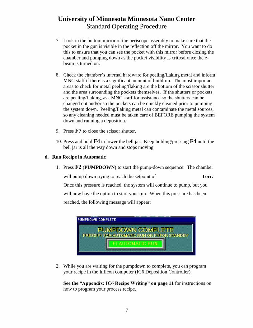
1. Press F2 (PUMPDOWN) to start the pump-down sequence. The chamber
will pump down trying to reach the setpoint of Torr.
Once this pressure is reached, the system will continue to pump, but you
will now have the option to start your run. When this pressure has been
reached, the following message will appear:
2. While you are waiting for the pumpdown to complete, you can program
your recipe in the Inficon computer (IC6 Deposition Controller).
See the “Appendix: IC6 Recipe Writing” on page 11 for instructions on
how to program your process recipe.
University of Minnesota Minnesota Nano Center
Standard Operating Procedure
8
3. Zero out the X and Y offsets on the MDC sweep controller for a safe initial
beam position. The Program button, ‘PRM’, should already be highlighted
(if not, press PRM). The beam position can be adjusted by pressing the
corresponding X or Y axis button on the MDC sweep controller. Use the
hand controller to adjust the X and Y offsets as needed during the run. For
now, adjust them both to 0.0
4. Press F1 (Automatic) to start an automatic process run. If a lower pressure
is desired, wait until that pressure has been reached before pressing F1.
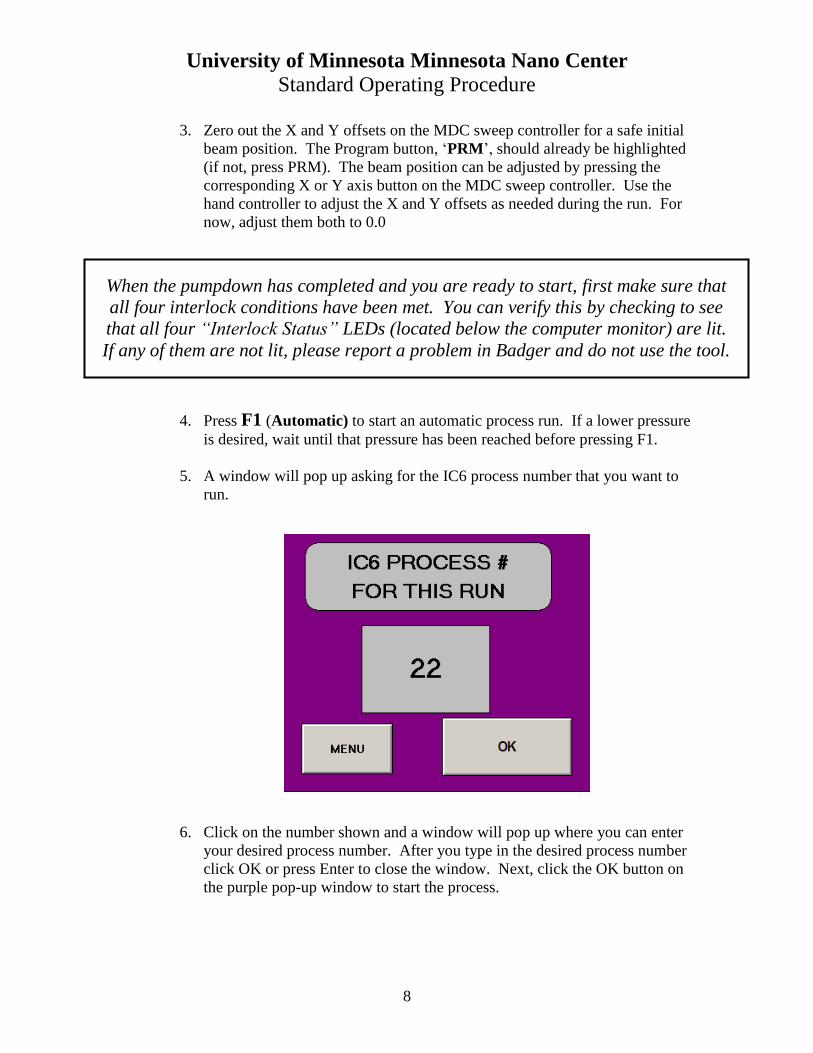
5. A window will pop up asking for the IC6 process number that you want to
run.
6. Click on the number shown and a window will pop up where you can enter
your desired process number. After you type in the desired process number
click OK or press Enter to close the window. Next, click the OK button on
the purple pop-up window to start the process.
When the pumpdown has completed and you are ready to start, first make sure that
all four interlock conditions have been met. You can verify this by checking to see
that all four “Interlock Status” LEDs (located below the computer monitor) are lit.
If any of them are not lit, please report a problem in Badger and do not use the tool.
University of Minnesota Minnesota Nano Center
Standard Operating Procedure
9
The gun turret should rotate to the correct pocket. Check to confirm that the
pocket number is correct by looking at the “Hearth Controller” which is
located to the right of the “Sweep Controller”, below the bell jar. There
should be a red digital number displayed (1 through 6).
7. Observe the beam inside the chamber. If it is too bright, use UV protective
glasses or a piece of tinted glass (located on the CHA metal supply cabinet.
The Program button ‘PRM’ should already be highlighted (if not, press
PRM). Adjust the beam position as needed using the MDC sweep
controller. The beam can be adjusted by pressing the corresponding X or Y
axis button on the MDC sweep controller. Use the hand controller to adjust
the beam by pressing the up or down arrow buttons. Be sure to look inside
the chamber at the beam while you are changing the X or Y axis settings to
determine where the beam is moving.
8. When the target thickness has been reached, the shutter will close
automatically and the beam will shut off. A message will pop up asking if
you want to vent the chamber. Wait at least 10 more minutes for the sources
to cool before venting.
After you are finished cooling the metal source, vent the chamber by left
clicking on YES or pressing F9. When the system is vented, a message
will pop up saying “PROCESS COMPLETE”. Press F4 (or press A) to
enter standby. Wait about 10 seconds, and then click “OK” (or press A)
when the SYSTEM IN STANDBY message appears. Press and hold F5 to
raise the bell jar, and then unload your wafers.
9. If you loaded any sources in to pockets 4, 5, or 6, remove them from the
system. To do this, press F7 to open the scissor shutter. Then press F6 to
rotate the gun to a different pocket. A window will pop up with different
pocket numbers. Select the desired pocket(s) by pressing the appropriate
number on the keypad or by clicking on the desired pocket number on the
Siemens computer screen using the mouse/track-pad. The gun will slowly
rotate to the pocket you selected.
Note: If you used the gold source during your run (or platinum or
palladium), you need to weigh the precious metal source (and the two
buttons) one more time before closing the bell jar. Record these weights in
the CHA log book.
University of Minnesota Minnesota Nano Center
Standard Operating Procedure
10
e. Idle State: The CHA is ALWAYS to be left pumped down.
1. Press and hold F4 to lower the bell jar. Keep holding/pressing F4 until the
bell jar is all the way down and stops moving. Then press F2 (PUMPDOWN) to pump the system back down. The system will do a soft
roughing pump-down for 1-2 minutes, and then it will switch to a regular
roughing pump-down for several minutes. The chamber animation on the
screen will gradually change from green to gray indicating that it is
pumping. When the cross-over pressure setpoint is reached, the roughing
valve will close automatically and the system will then measure the “rate of
rise” (i.e. leak-up rate). If the system is satisfied with the “rate of rise” test,
it will automatically cross over into high vacuum and you will hear the high
vacuum valve open.
2. Stay with the system until “IG2 SETPOINT 1 IS BEING MADE” is
displayed on the screen. (If this does not happen within 10 minutes after
starting the pump-down, contact an MNC staff member). After this, you can
disable the CHA in the Badger system. If you did use the gold source
during the run, you will need to calculate how much gold you used (in
milligrams). An example is listed in the table at the top of the next page.
Beginning Weight 172.53 grams
Ending Weight 170.41 grams
Total Gold Used (in milligrams) 2.12 grams = 2120 milligrams
In Badger, click on the “Supplies” menu, and select “Check Out”. You
will then notice a supply list that appears on the left side within the Badger
window. Scroll down the list and click on “evap gold” (or “evap platinum”
or “evap palladium” if those were used). Then you will see that supply
name appear in the “Supply” field box. In the “Quantity” field box, enter
the number of milligrams of gold (or Pt or Pd) that was used (which was
2120 mg in the example above). Click on “Save & Close”.
3. Finish filling out the log book (e.g. your name, the date, your materials,
pocket numbers, deposition rates, thicknesses, percent crystal life, etc.). If
you used any precious metals (Au, Pd, or Pt), please be sure to record the
beginning and ending weights for these sources in the CHA log book.
University of Minnesota Minnesota Nano Center
Standard Operating Procedure
11
8. Appendix: IC6 Recipe Writing
a. WRITING A PROCESS RECIPE (INIFICON COMPUTER)
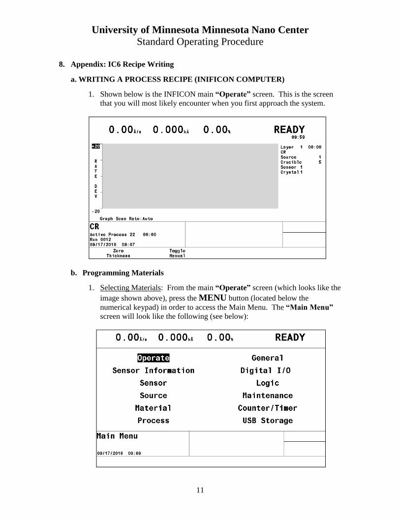
1. Shown below is the INFICON main “Operate” screen. This is the screen
that you will most likely encounter when you first approach the system.
b. Programming Materials
1. Selecting Materials: From the main “Operate” screen (which looks like the
image shown above), press the MENU button (located below the
numerical keypad) in order to access the Main Menu. The “Main Menu”
screen will look like the following (see below):
University of Minnesota Minnesota Nano Center
Standard Operating Procedure
12
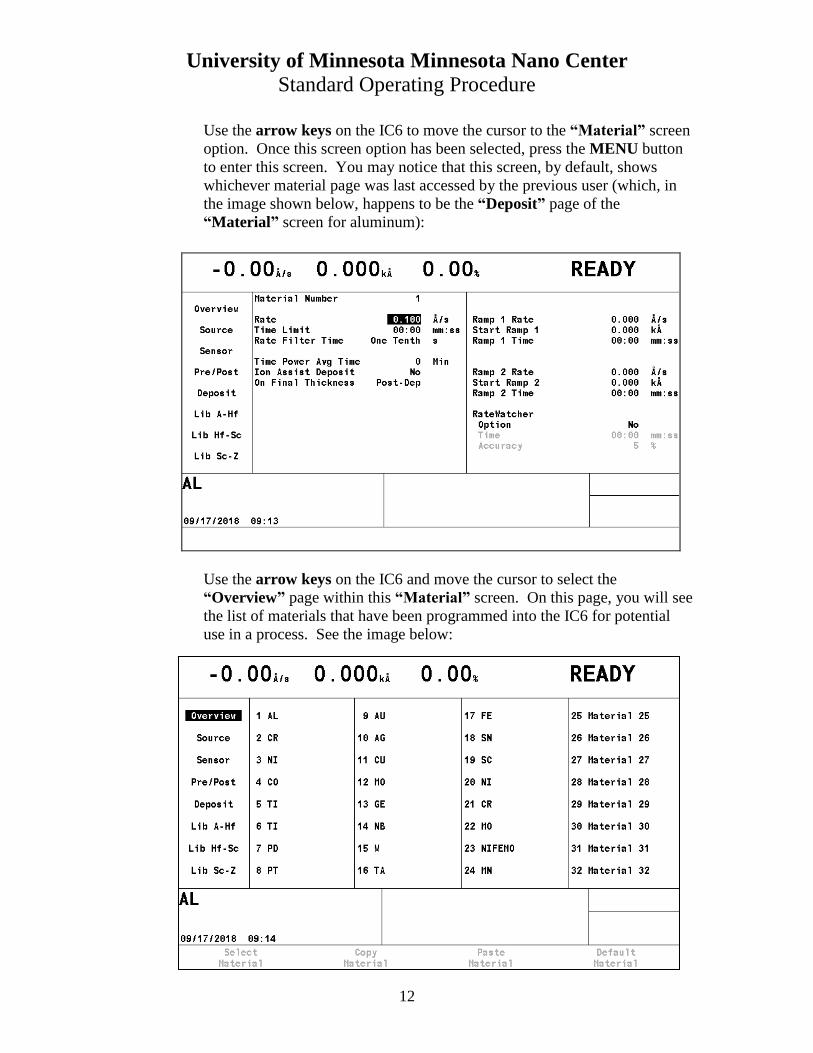
Use the arrow keys on the IC6 to move the cursor to the “Material” screen
option. Once this screen option has been selected, press the MENU button
to enter this screen. You may notice that this screen, by default, shows
whichever material page was last accessed by the previous user (which, in
the image shown below, happens to be the “Deposit” page of the
“Material” screen for aluminum):
Use the arrow keys on the IC6 and move the cursor to select the
“Overview” page within this “Material” screen. On this page, you will see
the list of materials that have been programmed into the IC6 for potential
use in a process. See the image below:
University of Minnesota Minnesota Nano Center
Standard Operating Procedure
13
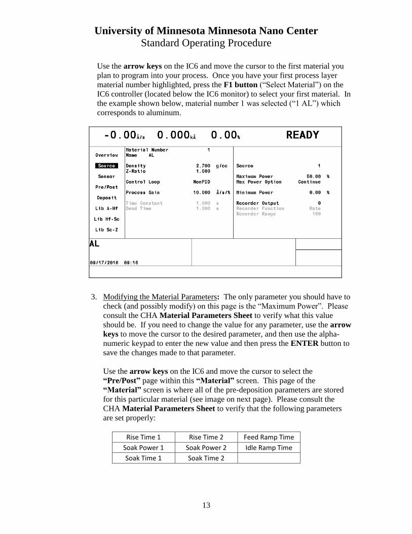
Use the arrow keys on the IC6 and move the cursor to the first material you
plan to program into your process. Once you have your first process layer
material number highlighted, press the F1 button (“Select Material”) on the
IC6 controller (located below the IC6 monitor) to select your first material. In
the example shown below, material number 1 was selected (“1 AL”) which
corresponds to aluminum.
3. Modifying the Material Parameters: The only parameter you should have to
check (and possibly modify) on this page is the “Maximum Power”. Please
consult the CHA Material Parameters Sheet to verify what this value
should be. If you need to change the value for any parameter, use the arrow
keys to move the cursor to the desired parameter, and then use the alpha-
numeric keypad to enter the new value and then press the ENTER button to
save the changes made to that parameter.
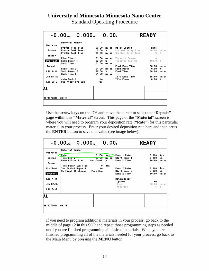
Use the arrow keys on the IC6 and move the cursor to select the
“Pre/Post” page within this “Material” screen. This page of the
“Material” screen is where all of the pre-deposition parameters are stored
for this particular material (see image on next page). Please consult the
CHA Material Parameters Sheet to verify that the following parameters
are set properly:
Rise Time 1 Rise Time 2 Feed Ramp Time
Soak Power 1 Soak Power 2 Idle Ramp Time
Soak Time 1 Soak Time 2
University of Minnesota Minnesota Nano Center
Standard Operating Procedure
14
Use the arrow keys on the IC6 and move the cursor to select the “Deposit”
page within this “Material” screen. This page of the “Material” screen is
where you will need to program your deposition rate (“Rate”) for this particular
material in your process. Enter your desired deposition rate here and then press
the ENTER button to save this value (see image below).
If you need to program additional materials in your process, go back to the
middle of page 12 in this SOP and repeat those programming steps as needed
until you are finished programming all desired materials. When you are
finished programming all of the materials needed for your process, go back to
the Main Menu by pressing the MENU button.
University of Minnesota Minnesota Nano Center
Standard Operating Procedure
15
c. Programming Processes
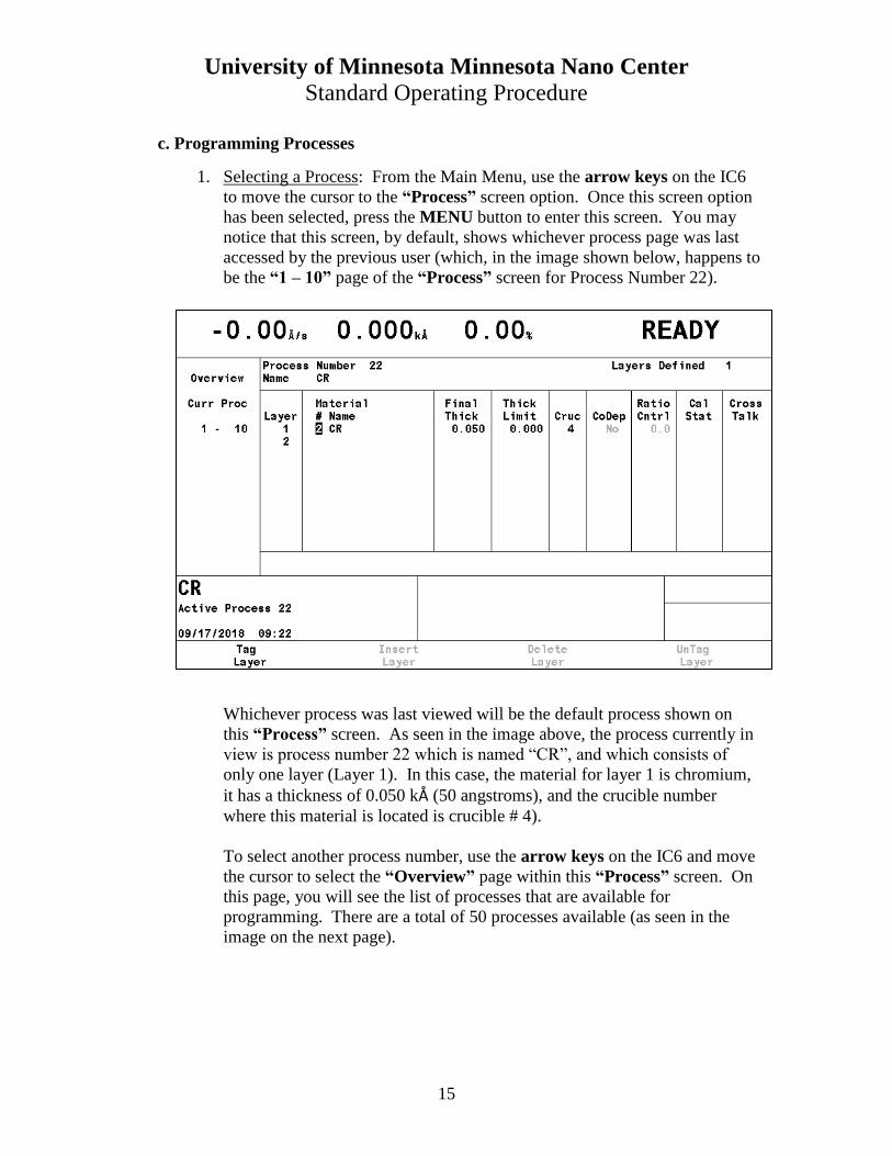
1. Selecting a Process: From the Main Menu, use the arrow keys on the IC6
to move the cursor to the “Process” screen option. Once this screen option
has been selected, press the MENU button to enter this screen. You may
notice that this screen, by default, shows whichever process page was last
accessed by the previous user (which, in the image shown below, happens to
be the “1 – 10” page of the “Process” screen for Process Number 22).
Whichever process was last viewed will be the default process shown on
this “Process” screen. As seen in the image above, the process currently in
view is process number 22 which is named “CR”, and which consists of
only one layer (Layer 1). In this case, the material for layer 1 is chromium,
it has a thickness of 0.050 kÅ (50 angstroms), and the crucible number
where this material is located is crucible # 4).
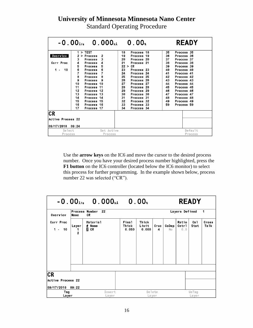
To select another process number, use the arrow keys on the IC6 and move
the cursor to select the “Overview” page within this “Process” screen. On
this page, you will see the list of processes that are available for
programming. There are a total of 50 processes available (as seen in the
image on the next page).
University of Minnesota Minnesota Nano Center
Standard Operating Procedure
16
Use the arrow keys on the IC6 and move the cursor to the desired process
number. Once you have your desired process number highlighted, press the
F1 button on the IC6 controller (located below the IC6 monitor) to select
this process for further programming. In the example shown below, process
number 22 was selected (“CR”).
University of Minnesota Minnesota Nano Center
Standard Operating Procedure
17
2. Modifying the Process Parameters: Use the arrow keys on the IC6 and move the
cursor to the far left column in order to select the “1 – 10” page option on this
process screen. Next, use the arrow keys to move the cursor to any parameter
within your process that you want to edit. The following parameters can be edited
as needed:
- Process name (“Name”)
- Material number (“Material #”)
- Final thickness (“Final Thick”)
- Crucible number (“Cruc”)
To change the process name (“Name”), use the arrow keys to move the cursor
over to the current name. Press any number on the alpha-numeric keypad to enter
the editing-mode for the process name. Pressing the left arrow key can be
used to delete characters and the alpha-numeric keypad can be used to add
characters. To add new characters to a name, simply press the alpha-numeric
key corresponding to the letter of interest (for example, the number 2 on the
keypad corresponds to the letters “A”, “B”, and “C”). Pressing any particular
number several times in a row will allow you to select different letters contained
within that key. For example, if you want to type in the letter “C”, then you
would press the number “2” three times since “C” is the third letter in that key,
and if you wanted to select the letter “E”, then you would press the number “3”
two times since “E” is the second letter in that key, etc. So if you wanted to type
in the word “GOLD”, then the keystrokes would be “4-6-6-6-5-5-5-3”. When you
are finished editing the process name, press the ENTER button on the IC6 to save
the changes.
To change the material number (“Material #”), use the arrow keys to move the
cursor over to the current material number, which is located just to the right of the
layer number. Type in the number of the material you want to deposit, as listed in
the “Material” screen, and then press the ENTER button. If it is a commonly
used material, you may also find the material number listed on the Material
Parameters Sheet in the SOP booklet.
To change the final thickness (“Final Thick”), use the arrow keys to move the
cursor over to the current final thickness value, and enter the desired thickness for
this layer and then press the ENTER button. The units for this quantity are kÅ
(kilo-angstroms) which means that 50Å would be entered as 0.050 kÅ.
To change the crucible number (“Cruc”), use the arrow keys to move the cursor
over to that parameter, and enter the desired pocket number where this layer’s
material is being stored in the hearth. For example, if this layer was intended to
be gold (Au) then I would enter a crucible number of “3” since the gold is always
stored in this pocket. Press the ENTER button to save this value.
University of Minnesota Minnesota Nano Center
Standard Operating Procedure
18
Remember that you can add several layers to a process, and if a new
additional layer is desired, simply use the arrow keys to move the cursor
over to the right of the next layer number, and enter in the material number
(“Material #”) corresponding to this new desired layer, and then press the
ENTER button. Now you can edit the final thickness and crucible
parameters for this new layer just as you did with the previous layer(s) in the
process.
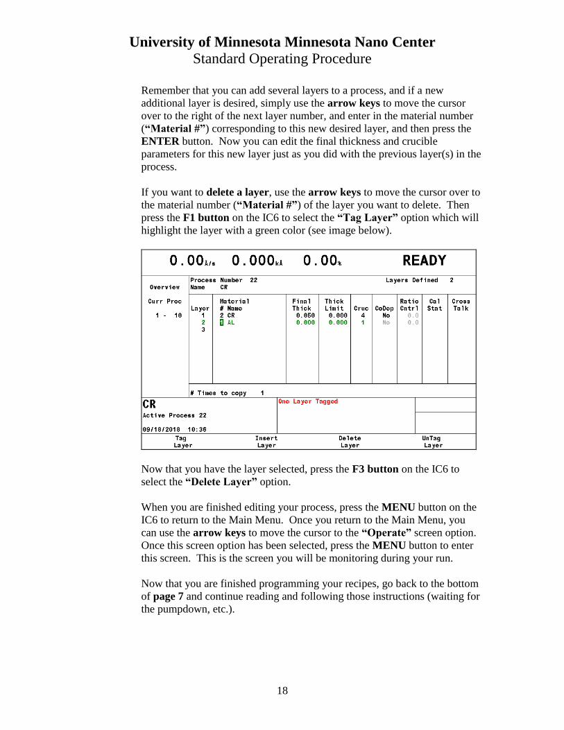
If you want to delete a layer, use the arrow keys to move the cursor over to
the material number (“Material #”) of the layer you want to delete. Then
press the F1 button on the IC6 to select the “Tag Layer” option which will
highlight the layer with a green color (see image below).
Now that you have the layer selected, press the F3 button on the IC6 to
select the “Delete Layer” option.
When you are finished editing your process, press the MENU button on the
IC6 to return to the Main Menu. Once you return to the Main Menu, you
can use the arrow keys to move the cursor to the “Operate” screen option.
Once this screen option has been selected, press the MENU button to enter
this screen. This is the screen you will be monitoring during your run.
Now that you are finished programming your recipes, go back to the bottom
of page 7 and continue reading and following those instructions (waiting for
the pumpdown, etc.).