Embed Size (px)
Citation preview
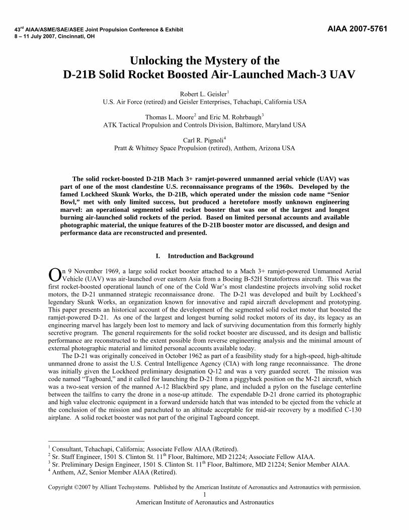
43rd AIAA/ASME/SAE/ASEE Joint Propulsion Conference & Exhibit AIAA 2007-5761 8 – 11 July 2007, Cincinnati, OH
1 American Institute of Aeronautics and Astronautics
Unlocking the Mystery of the D-21B Solid Rocket Boosted Air-Launched Mach-3 UAV
Robert L. Geisler1
U.S. Air Force (retired) and Geisler Enterprises, Tehachapi, California USA
Thomas L. Moore2 and Eric M. Rohrbaugh3
ATK Tactical Propulsion and Controls Division, Baltimore, Maryland USA
Carl R. Pignoli4
Pratt & Whitney Space Propulsion (retired), Anthem, Arizona USA
The solid rocket-boosted D-21B Mach 3+ ramjet-powered unmanned aerial vehicle (UAV) was
part of one of the most clandestine U.S. reconnaissance programs of the 1960s. Developed by the famed Lockheed Skunk Works, the D-21B, which operated under the mission code name “Senior Bowl,” met with only limited success, but produced a heretofore mostly unknown engineering marvel: an operational segmented solid rocket booster that was one of the largest and longest burning air-launched solid rockets of the period. Based on limited personal accounts and available photographic material, the unique features of the D-21B booster motor are discussed, and design and performance data are reconstructed and presented.
I. Introduction and Background
n 9 November 1969, a large solid rocket booster attached to a Mach 3+ ramjet-powered Unmanned Aerial Vehicle (UAV) was air-launched over eastern Asia from a Boeing B-52H Stratofortress aircraft. This was the
first rocket-boosted operational launch of one of the Cold War’s most clandestine projects involving solid rocket motors, the D-21 unmanned strategic reconnaissance drone. The D-21 was developed and built by Lockheed’s legendary Skunk Works, an organization known for innovative and rapid aircraft development and prototyping. This paper presents an historical account of the development of the segmented solid rocket motor that boosted the ramjet-powered D-21. As one of the largest and longest burning solid rocket motors of its day, its legacy as an engineering marvel has largely been lost to memory and lack of surviving documentation from this formerly highly secretive program. The general requirements for the solid rocket booster are discussed, and its design and ballistic performance are reconstructed to the extent possible from reverse engineering analysis and the minimal amount of external photographic material and limited personal accounts available today.
O
The D-21 was originally conceived in October 1962 as part of a feasibility study for a high-speed, high-altitude unmanned drone to assist the U.S. Central Intelligence Agency (CIA) with long range reconnaissance. The drone was initially given the Lockheed preliminary designation Q-12 and was a very guarded secret. The mission was code named “Tagboard,” and it called for launching the D-21 from a piggyback position on the M-21 aircraft, which was a two-seat version of the manned A-12 Blackbird spy plane, and included a pylon on the fuselage centerline between the tailfins to carry the drone in a nose-up attitude. The expendable D-21 drone carried its photographic and high value electronic equipment in a forward underside hatch that was intended to be ejected from the vehicle at the conclusion of the mission and parachuted to an altitude acceptable for mid-air recovery by a modified C-130 airplane. A solid rocket booster was not part of the original Tagboard concept.
1 Consultant, Tehachapi, California; Associate Fellow AIAA (Retired). 2 Sr. Staff Engineer, 1501 S. Clinton St. 11 Floor, Baltimore, MD 21224; Associate Fellow AIAA.th
3 Sr. Preliminary Design Engineer, 1501 S. Clinton St. 11th Floor, Baltimore, MD 21224; Senior Member AIAA. 4 Anthem, AZ, Senior Member AIAA (Retired). Copyright ©2007 by Alliant Techsystems. Published by the American Institute of Aeronautics and Astronautics with permission.
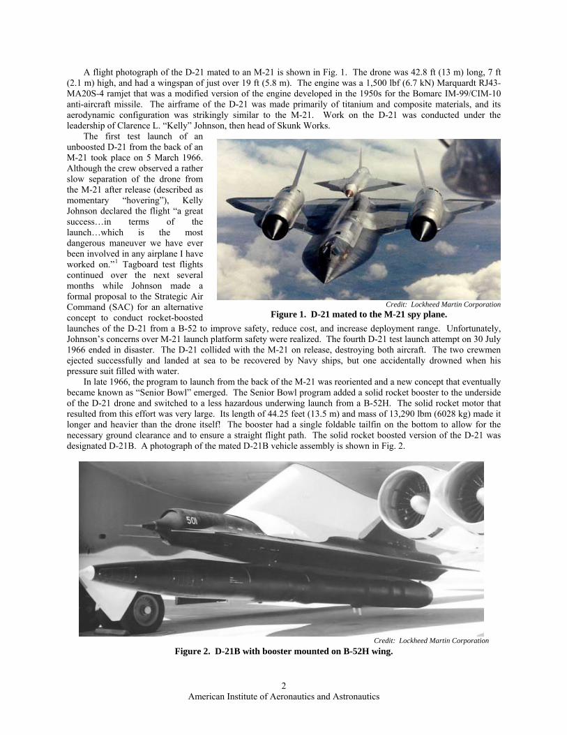
A flight photograph of the D-21 mated to an M-21 is shown in Fig. 1. The drone was 42.8 ft (13 m) long, 7 ft (2.1 m) high, and had a wingspan of just over 19 ft (5.8 m). The engine was a 1,500 lbf (6.7 kN) Marquardt RJ43-MA20S-4 ramjet that was a modified version of the engine developed in the 1950s for the Bomarc IM-99/CIM-10 anti-aircraft missile. The airframe of the D-21 was made primarily of titanium and composite materials, and its aerodynamic configuration was strikingly similar to the M-21. Work on the D-21 was conducted under the leadership of Clarence L. “Kelly” Johnson, then head of Skunk Works.
The first test launch of an unboosted D-21 from the back of an M-21 took place on 5 March 1966. Although the crew observed a rather slow separation of the drone from the M-21 after release (described as momentary “hovering”), Kelly Johnson declared the flight “a great success…in terms of the launch…which is the most dangerous maneuver we have ever been involved in any airplane I have worked on.”1 Tagboard test flights continued over the next several months while Johnson made a formal proposal to the Strategic Air Command (SAC) for an alternative concept to conduct rocket-boosted launches of the D-21 from a B-52 to improve safety, reduce cost, and increase deployment range. Unfortunately, Johnson’s concerns over M-21 launch platform safety were realized. The fourth D-21 test launch attempt on 30 July 1966 ended in disaster. The D-21 collided with the M-21 on release, destroying both aircraft. The two crewmen ejected successfully and landed at sea to be recovered by Navy ships, but one accidentally drowned when his pressure suit filled with water.
Credit: Lockheed Martin Corporation
Figure 1. D-21 mated to the M-21 spy plane.
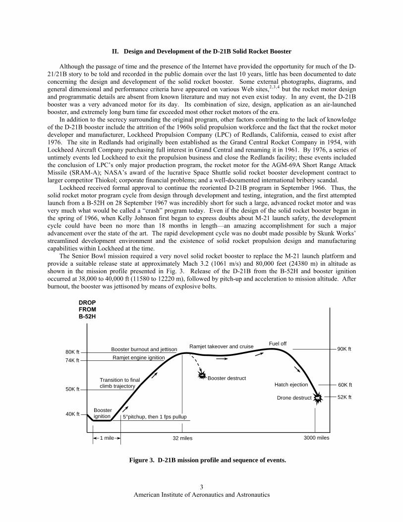
In late 1966, the program to launch from the back of the M-21 was reoriented and a new concept that eventually became known as “Senior Bowl” emerged. The Senior Bowl program added a solid rocket booster to the underside of the D-21 drone and switched to a less hazardous underwing launch from a B-52H. The solid rocket motor that resulted from this effort was very large. Its length of 44.25 feet (13.5 m) and mass of 13,290 lbm (6028 kg) made it longer and heavier than the drone itself! The booster had a single foldable tailfin on the bottom to allow for the necessary ground clearance and to ensure a straight flight path. The solid rocket boosted version of the D-21 was designated D-21B. A photograph of the mated D-21B vehicle assembly is shown in Fig. 2.
Credit: Lockheed Martin Corporation
Figure 2. D-21B with booster mounted on B-52H wing.
2 American Institute of Aeronautics and Astronautics
II. Design and Development of the D-21B Solid Rocket Booster
Although the passage of time and the presence of the Internet have provided the opportunity for much of the D-21/21B story to be told and recorded in the public domain over the last 10 years, little has been documented to date concerning the design and development of the solid rocket booster. Some external photographs, diagrams, and general dimensional and performance criteria have appeared on various Web sites,2, ,3 4 but the rocket motor design and programmatic details are absent from known literature and may not even exist today. In any event, the D-21B booster was a very advanced motor for its day. Its combination of size, design, application as an air-launched booster, and extremely long burn time far exceeded most other rocket motors of the era.
In addition to the secrecy surrounding the original program, other factors contributing to the lack of knowledge of the D-21B booster include the attrition of the 1960s solid propulsion workforce and the fact that the rocket motor developer and manufacturer, Lockheed Propulsion Company (LPC) of Redlands, California, ceased to exist after 1976. The site in Redlands had originally been established as the Grand Central Rocket Company in 1954, with Lockheed Aircraft Company purchasing full interest in Grand Central and renaming it in 1961. By 1976, a series of untimely events led Lockheed to exit the propulsion business and close the Redlands facility; these events included the conclusion of LPC’s only major production program, the rocket motor for the AGM-69A Short Range Attack Missile (SRAM-A); NASA’s award of the lucrative Space Shuttle solid rocket booster development contract to larger competitor Thiokol; corporate financial problems; and a well-documented international bribery scandal.
Lockheed received formal approval to continue the reoriented D-21B program in September 1966. Thus, the solid rocket motor program cycle from design through development and testing, integration, and the first attempted launch from a B-52H on 28 September 1967 was incredibly short for such a large, advanced rocket motor and was very much what would be called a “crash” program today. Even if the design of the solid rocket booster began in the spring of 1966, when Kelly Johnson first began to express doubts about M-21 launch safety, the development cycle could have been no more than 18 months in length—an amazing accomplishment for such a major advancement over the state of the art. The rapid development cycle was no doubt made possible by Skunk Works’ streamlined development environment and the existence of solid rocket propulsion design and manufacturing capabilities within Lockheed at the time.
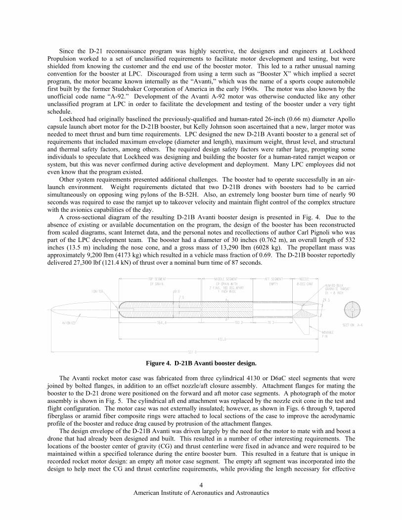
The Senior Bowl mission required a very novel solid rocket booster to replace the M-21 launch platform and provide a suitable release state at approximately Mach 3.2 (1061 m/s) and 80,000 feet (24380 m) in altitude as shown in the mission profile presented in Fig. 3. Release of the D-21B from the B-52H and booster ignition occurred at 38,000 to 40,000 ft (11580 to 12220 m), followed by pitch-up and acceleration to mission altitude. After burnout, the booster was jettisoned by means of explosive bolts.
1 mile
52K ft
Ramjet takeover and cruise
32 miles 3000 miles
40K ft
90K ft 80K ft Booster burnout and jettisonRamjet engine ignition74K ft
5°pitchup, then 1 fps pullup
Transition to final climb trajectory 50K ft
Booster ignition
DROP FROM B-52H
60K ft Hatch ejection
Drone destruct
Fuel off
Booster destruct
Figure 3. D-21B mission profile and sequence of events.
3 American Institute of Aeronautics and Astronautics
Since the D-21 reconnaissance program was highly secretive, the designers and engineers at Lockheed Propulsion worked to a set of unclassified requirements to facilitate motor development and testing, but were shielded from knowing the customer and the end use of the booster motor. This led to a rather unusual naming convention for the booster at LPC. Discouraged from using a term such as “Booster X” which implied a secret program, the motor became known internally as the “Avanti,” which was the name of a sports coupe automobile first built by the former Studebaker Corporation of America in the early 1960s. The motor was also known by the unofficial code name “A-92.” Development of the Avanti A-92 motor was otherwise conducted like any other unclassified program at LPC in order to facilitate the development and testing of the booster under a very tight schedule.
Lockheed had originally baselined the previously-qualified and human-rated 26-inch (0.66 m) diameter Apollo capsule launch abort motor for the D-21B booster, but Kelly Johnson soon ascertained that a new, larger motor was needed to meet thrust and burn time requirements. LPC designed the new D-21B Avanti booster to a general set of requirements that included maximum envelope (diameter and length), maximum weight, thrust level, and structural and thermal safety factors, among others. The required design safety factors were rather large, prompting some individuals to speculate that Lockheed was designing and building the booster for a human-rated ramjet weapon or system, but this was never confirmed during active development and deployment. Many LPC employees did not even know that the program existed.
Other system requirements presented additional challenges. The booster had to operate successfully in an air-launch environment. Weight requirements dictated that two D-21B drones with boosters had to be carried simultaneously on opposing wing pylons of the B-52H. Also, an extremely long booster burn time of nearly 90 seconds was required to ease the ramjet up to takeover velocity and maintain flight control of the complex structure with the avionics capabilities of the day.
A cross-sectional diagram of the resulting D-21B Avanti booster design is presented in Fig. 4. Due to the absence of existing or available documentation on the program, the design of the booster has been reconstructed from scaled diagrams, scant Internet data, and the personal notes and recollections of author Carl Pignoli who was part of the LPC development team. The booster had a diameter of 30 inches (0.762 m), an overall length of 532 inches (13.5 m) including the nose cone, and a gross mass of 13,290 lbm (6028 kg). The propellant mass was approximately 9,200 lbm (4173 kg) which resulted in a vehicle mass fraction of 0.69. The D-21B booster reportedly delivered 27,300 lbf (121.4 kN) of thrust over a nominal burn time of 87 seconds.
Figure 4. D-21B Avanti booster design.
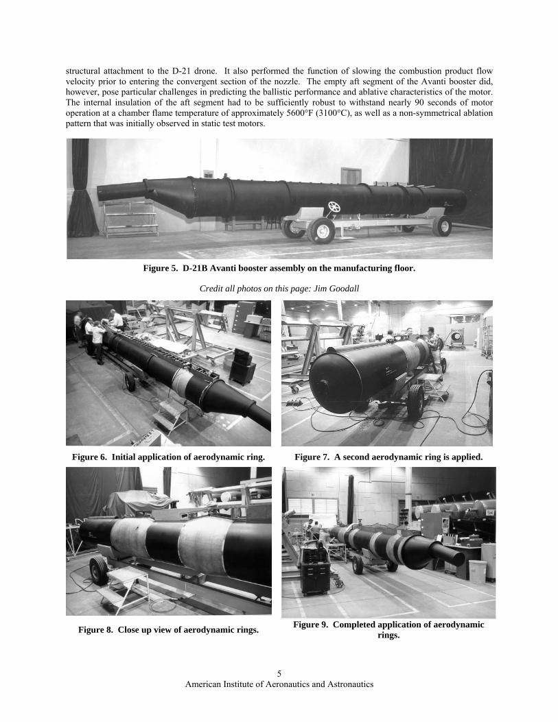
The Avanti rocket motor case was fabricated from three cylindrical 4130 or D6aC steel segments that were
joined by bolted flanges, in addition to an offset nozzle/aft closure assembly. Attachment flanges for mating the booster to the D-21 drone were positioned on the forward and aft motor case segments. A photograph of the motor assembly is shown in Fig. 5. The cylindrical aft end attachment was replaced by the nozzle exit cone in the test and flight configuration. The motor case was not externally insulated; however, as shown in Figs. 6 through 9, tapered fiberglass or aramid fiber composite rings were attached to local sections of the case to improve the aerodynamic profile of the booster and reduce drag caused by protrusion of the attachment flanges.
The design envelope of the D-21B Avanti was driven largely by the need for the motor to mate with and boost a drone that had already been designed and built. This resulted in a number of other interesting requirements. The locations of the booster center of gravity (CG) and thrust centerline were fixed in advance and were required to be maintained within a specified tolerance during the entire booster burn. This resulted in a feature that is unique in recorded rocket motor design: an empty aft motor case segment. The empty aft segment was incorporated into the design to help meet the CG and thrust centerline requirements, while providing the length necessary for effective
4 American Institute of Aeronautics and Astronautics
structural attachment to the D-21 drone. It also performed the function of slowing the combustion product flow velocity prior to entering the convergent section of the nozzle. The empty aft segment of the Avanti booster did, however, pose particular challenges in predicting the ballistic performance and ablative characteristics of the motor. The internal insulation of the aft segment had to be sufficiently robust to withstand nearly 90 seconds of motor operation at a chamber flame temperature of approximately 5600°F (3100°C), as well as a non-symmetrical ablation pattern that was initially observed in static test motors.
Figure 5. D-21B Avanti booster assembly on the manufacturing floor.
Credit all photos on this page: Jim Goodall
Figure 6. Initial application of aerodynamic ring. Figure 7. A second aerodynamic ring is applied.
Figure 9. Completed application of aerodynamic
rings. Figure 8. Close up view of aerodynamic rings.
5 American Institute of Aeronautics and Astronautics
Lockheed Propulsion Company selected the propellant and grain configuration based on the company’s experience base in composite propellants. The propellant was a conventional aluminized formulation containing approximately 70% ammonium perchlorate (AP) oxidizer by weight, 14% polybutadiene-acrylic acid-acrylonitrile (PBAN) binder and additives, and 16% aluminum fuel. The propellant likely contained a coolant additive and/or a large AP particle size distribution to lower the burning rate. The propellant had to successfully withstand a rather large temperature range typical of air launch requirements, probably on the order of -65°F (54°C) to +160°F (70°C). The booster contained separate case-bonded propellant grains cast into the forward and center case segments. The forward grain configuration was a simple center perforated (CP) cylinder that would produce a naturally progressive thrust profile in and of itself, while the center segment (aft) grain was a regressive-burning double slotted CP. LPC had previously tested the opposed double slotted CP configuration on smaller rocket motors over a similar operating temperature range which provided confidence in the approach. The rocket motor igniter was a forward-mounted pyrogen (rocket) type with a boron-potassium nitrate (B/KNO3) booster charge and dual initiators.
The internal insulation system of the segmented motor, shown in Fig. 10, was designed to provide thermal protection of the case during the lengthy burn time and provide a stress relief system so the propellant grain could withstand the operating temperature range. Lockheed used standard materials of the day, V-45 silica-filled nitrile butadiene rubber (NBR) and V-44 asbestos-filled NBR, to insulate the motor case. V-45 was used in the forward segment, while either V-45 or a combination of V-45 and V-44 was used in the center and aft segments. To reduce propellant stresses in the forward segment, the grain was released (unbonded) in the forward dome and at the aft end, and a unique stress relief “bulb” was built in at the tangent point. The insulation in the center segment was also released at both ends. All insulation was hand applied and autoclave cured in place.
Full Forward Dome Flap Forward Segment
Stress Relief BulbSplit Aft Insulator
Pyrogen Igniter
Propellant Grain
Propellant Grain
Center SegmentSlot Insulation
Slot Insulator 1.5” Wide Slot
Insulated Empty Aft Segment
Full Forward Dome Flap Forward Segment
Stress Relief BulbSplit Aft Insulator
Pyrogen Igniter
Propellant Grain
Propellant Grain
Center SegmentSlot Insulation
Slot Insulator 1.5” Wide Slot
Insulated Empty Aft Segment
Figure 10. D-21B Avanti insulation design.
6 American Institute of Aeronautics and Astronautics
The D-21B Avanti grain design produced very high initial combustion flow velocities down the grain slots which tapered off during burnback, as well as non-symmetrical ablation in the empty aft segment. This condition required special consideration for sizing the insulation. Determination of insulation thickness and contour for the booster was based upon exposure time and combustion product flow velocity over the specific location. To further validate the insulation design, Lockheed conducted correlation studies using test data from other programs. A representative correlation curve used to size the Avanti booster insulation system is presented in Fig. 11. In this case, the ablation rate for filled Buna-N rubber is correlated to combustion product flow velocity (ė), chamber pressure (Pc), and chamber diameter (Dc).
1
10
100
10 100 1000 10000
Combustion Products Flow Velocity, Vp (ft/sec)
Eros
ion
Rat
e, ė
, (m
il/se
c)
ė = 0.0308 Pc Vp0.617 Dc
-0.192
Reference conditions: Pc = 500 psi and Dc = 24 inches
Figure 11. Filled Buna-N rubber erosion characteristics.
As previously mentioned, the booster thrust centerline had to pass through a specific point and be maintained
within a range tolerance during motor operation. This requirement resulted in the rather unconventional nozzle design shown in Fig. 12. The throat was offset from the motor centerline, and the nozzle was canted 7 to 8 degrees to vector the thrust through the piggybacked vehicle center of gravity.
Thrust requirements also necessitated the use of materials to minimize throat erosion and possible non-axisymmetric thrust contributions. The throat insert was made of HLM-85 bulk graphite; the exit cone was constructed of tape-wrapped silica phenolic with a glass/epoxy overwrap; and the structural nozzle shell was fabricated from 4130 steel. The throat was also insulated with tape-wrapped silica phenolic. The throat diameter was about 8 inches (0.203 m) and the exit cone diameter about 24.5 inches (0.622 m), giving an area ratio of approximately 9.4.
To mate the nozzle to the motor chamber, an offset conical aft closure made of 4130 or D6aC steel was used. It was insulated with either V-44 asbestos-filled nitrile butadiene rubber (NBR) or MXCE-280 molded silica-carbon phenolic. The aft closure provided both the throat offset from the motor centerline and the cant angle to the nozzle. A scarfed nozzle design was also evaluated for the Avanti motor, but it was determined that the canted nozzle would provide a more predictable thrust angle centerline. Due to lack of published D-21B motor data, a ballistic performance prediction using modern analysis techniques was conducted to determine the nominal performance characteristics of the rocket motor. Using the limited design data available and the thermochemical properties of conventional aluminized PBAN composite propellants, this analysis produced the results shown in Table 1 and Fig. 13. The resulting performance profile confirmed that the combined burning of the dual grain configuration produced a progressive thrust profile with sharp tailoff that would gradually accelerate the drone to Mach 3 and help minimize CG shift during booster operation.
7 American Institute of Aeronautics and Astronautics
Ground testing of the D-21B booster was conducted in a large vertical test stand located at LPC’s former Potrero Creek site located off Highway 10 near Beaumont, California, about 30 miles east of the company’s main plant in Redlands. This facility had previously been used to test 120-inch and 156-inch diameter segmented motors that LPC had built and demonstrated under the Air Force 623A Program between 1962 and 1966.5 As depicted in the series of photographs in Figs. 14 through 19, the D-21B motor was fired in a vertical, nozzle-up attitude in either a three- or six-component thrust stand. Prior to testing, the booster was preconditioned to the specified temperature in an insulated metal tubular conditioning cell that was located immediately adjacent to the thrust stand. The conditioned motor was lifted from the chamber, placed in the thrust stand, and tested immediately. Post-static test photographs of a D-21B booster nozzle and aft closure are shown in Figs. 20 through 23.
Empty Aft Segment Plenum To Slow and Turn Gas
Asbestos filled NBR Insulation
Aft Closure
GLC Bulk Graphite (HLM-85)
Silica-Phenolic Tape
Silica-Phenolic Tape (Parallel to Centerline) With Glass/Epoxy Overwrap
Steel Shell
8°Motor
Centerline
Closure Centerline Nozzle Centerline
Figure 12. D-21B Avanti nozzle design.
Table 1. Predicted nominal performance of the D-21B Avanti booster.
Parameter Predicted Value
Burn time, sec 87.0
Maximum Pressure, psi (MPa) 370 (2.551)
Average Pressure, psi (MPa) 329 (2.268)
Maximum Thrust, lbf (kN) 30,665 (136.4)
Average Thrust, lbf (kN) 27,268 (121.3)
Total Impulse, lbf-sec (kN·s) 2,372,310 (10553)
Delivered Impulse, lbf-sec/lbm (kN·s/kg) 257.9 (2.529)
8 American Institute of Aeronautics and Astronautics
0
50
100
150
200
250
300
350
400
0 10 20 30 40 50 60 70 80 90 10
Time (sec)
Cha
mbe
r Pre
ssur
e (p
sia)
0
Figure 13. D-21B Avanti predicted performance profile.
Figure 14. Booster is removed from condition- ing cell in preparation for a cold static test.
Figure 15. Booster is lowered onto test stand.
9 American Institute of Aeronautics and Astronautics
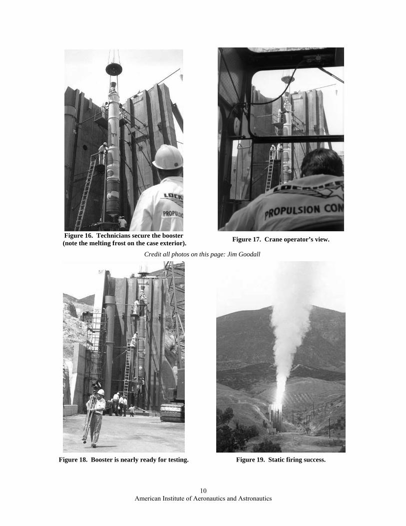
Figure 16. Technicians secure the booster
(note the melting frost on the case exterior). Figure 17. Crane operator’s view.
Credit all photos on this page: Jim Goodall
Figure 18. Booster is nearly ready for testing. Figure 19. Static firing success.
10 American Institute of Aeronautics and Astronautics
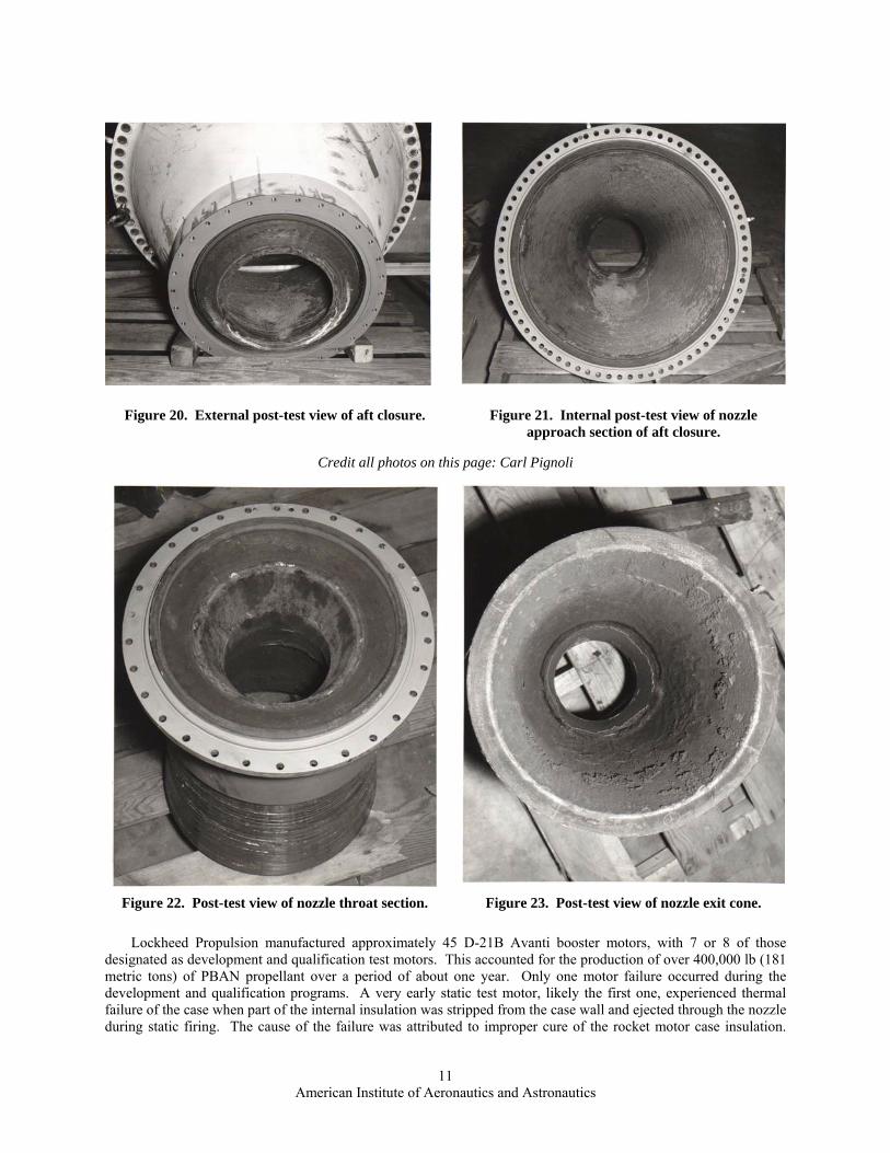
Figure 20. External post-test view of aft closure. Figure 21. Internal post-test view of nozzle approach section of aft closure.
Credit all photos on this page: Carl Pignoli
Figure 22. Post-test view of nozzle throat section. Figure 23. Post-test view of nozzle exit cone.
Lockheed Propulsion manufactured approximately 45 D-21B Avanti booster motors, with 7 or 8 of those designated as development and qualification test motors. This accounted for the production of over 400,000 lb (181 metric tons) of PBAN propellant over a period of about one year. Only one motor failure occurred during the development and qualification programs. A very early static test motor, likely the first one, experienced thermal failure of the case when part of the internal insulation was stripped from the case wall and ejected through the nozzle during static firing. The cause of the failure was attributed to improper cure of the rocket motor case insulation.
11 American Institute of Aeronautics and Astronautics
Corrective actions were implemented, and the remaining static tests of the D-21B motor were successful. The static test program also revealed a nonsymmetrical insulation ablation profile in the aft (empty) segment that required design modifications to withstand a higher ablation rate in the portion of the insulation approximately 90 degrees from the grain slots.
III. The Senior Bowl Test Program and Operational Flights
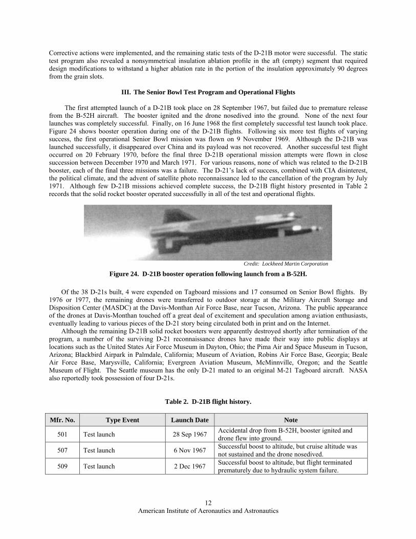
The first attempted launch of a D-21B took place on 28 September 1967, but failed due to premature release from the B-52H aircraft. The booster ignited and the drone nosedived into the ground. None of the next four launches was completely successful. Finally, on 16 June 1968 the first completely successful test launch took place. Figure 24 shows booster operation during one of the D-21B flights. Following six more test flights of varying success, the first operational Senior Bowl mission was flown on 9 November 1969. Although the D-21B was launched successfully, it disappeared over China and its payload was not recovered. Another successful test flight occurred on 20 February 1970, before the final three D-21B operational mission attempts were flown in close succession between December 1970 and March 1971. For various reasons, none of which was related to the D-21B booster, each of the final three missions was a failure. The D-21’s lack of success, combined with CIA disinterest, the political climate, and the advent of satellite photo reconnaissance led to the cancellation of the program by July 1971. Although few D-21B missions achieved complete success, the D-21B flight history presented in Table 2 records that the solid rocket booster operated successfully in all of the test and operational flights.
Credit: Lockheed Martin Corporation
Figure 24. D-21B booster operation following launch from a B-52H.
Of the 38 D-21s built, 4 were expended on Tagboard missions and 17 consumed on Senior Bowl flights. By 1976 or 1977, the remaining drones were transferred to outdoor storage at the Military Aircraft Storage and Disposition Center (MASDC) at the Davis-Monthan Air Force Base, near Tucson, Arizona. The public appearance of the drones at Davis-Monthan touched off a great deal of excitement and speculation among aviation enthusiasts, eventually leading to various pieces of the D-21 story being circulated both in print and on the Internet. Although the remaining D-21B solid rocket boosters were apparently destroyed shortly after termination of the program, a number of the surviving D-21 reconnaissance drones have made their way into public displays at locations such as the United States Air Force Museum in Dayton, Ohio; the Pima Air and Space Museum in Tucson, Arizona; Blackbird Airpark in Palmdale, California; Museum of Aviation, Robins Air Force Base, Georgia; Beale Air Force Base, Marysville, California; Evergreen Aviation Museum, McMinnville, Oregon; and the Seattle Museum of Flight. The Seattle museum has the only D-21 mated to an original M-21 Tagboard aircraft. NASA also reportedly took possession of four D-21s.
Table 2. D-21B flight history. Mfr. No. Type Event Launch Date Note
Accidental drop from B-52H, booster ignited and drone flew into ground. 501 Test launch 28 Sep 1967
Successful boost to altitude, but cruise altitude was not sustained and the drone nosedived. 507 Test launch 6 Nov 1967
509 Test launch 2 Dec 1967 Successful boost to altitude, but flight terminated prematurely due to hydraulic system failure.
12 American Institute of Aeronautics and Astronautics
Mfr. No. Type Event Launch Date Note Successful boost to altitude, but at 550 nmi, the drone pitched down and rolled to the left due to a probable electrical malfunction.
508 Test launch 19 Jan 1968
Successful boost to altitude, but drone was unable to sustain cruise (inlet not started) and was destroyed 150 nmi downrange.
511 Test launch 30 Apr 1968
Successful. Flew 2,850 nmi and reached 90,000 ft altitude. 512 Test launch 16 Jun 1968
Drone became unstable at top of boost phase due to autopilot malfunction. At separation, the booster struck the drone, rupturing the drone’s fuel tank. Hatch ejected and recovered. Flew 80 nmi.
514 Test launch 1 Jul 1968
Successful boost, but ramjet remained at minimum power and cruise altitude was not attained. Flew 78 nmi.
516 Test launch 28 Aug 1968
Successful. Flew 2,953 nmi and the hatch was successfully ejected and recovered. 515 Test launch 15 Dec 1968
Successful boost, but drone did not maintain cruise altitude due to autopilot error or failure. Drone suffered severe oscillations and was destroyed.
518 Test launch 11 Feb 1969
519 Test launch 10 May 1969 Successful. Flew 2,972 nmi and hatch recovered.
520 Test launch 10 July 1969 Successful. Flew 2,937 nmi and hatch recovered. Successful launch to 84.000 ft and Mach 3+, but drone disappeared and hatch was not recovered. 517 First operational launch 10 Nov 1969
Successful. Flew 2,969 nmi and reached 90,000 ft in altitude to validate changes to the guidance system. Hatch recovered.
521 Test launch 20 Feb 1970
Successful boost and flight. Flew 2,448 nmi, but imagery was not recovered. 523 Second operational launch 16 Dec 1970
Successful boost and flight. Flew 2,935 nmi, but imagery was not recovered. 526 Third operational launch 4 Mar 1971
Successful boost and launch, Flew 2,935 nmi, but drone was lost during flight. 527 Fourth operational launch 20 Mar 1971
IV. Closing Remarks and Conclusions
Even though the D-21B Senior Bowl program was cancelled after just four operational flights, it produced a solid rocket booster that was, by all accounts, a tremendous success and a mostly heretofore unknown technological marvel whose story was nearly lost to time. The designers of the D-21B Avanti booster faced many challenges in the era of hand drawings, manual calculations, and hand-plotting of data. In a period of less than 18 months between 1966 and 1967, the Lockheed Propulsion Company designed and produced a large, air-launched segmented motor with a nearly constant center of gravity and a burn time of 87 seconds in a 30-inch (0.76 m) diameter envelope. In addition, LPC formulated a propellant that had to burn at a rate of less than 0.16 inches (4.0 mm) per second when most conventional propellants burned twice as fast.
A low erosion throat was also necessary to meet the performance requirements of the D-21B Avanti booster. The conventional throat materials of the day could barely survive 60 seconds, and low erosion requirements routinely required the use of heavy and expensive tungsten. Lockheed insightfully turned to bulk graphite, which provided the necessary ablative characteristics and was reasonably inexpensive and readily available.
Performance requirements and propellant burning rate issues were largely solved by operating at low pressure with grains that burned radially and had a large web thickness. The thick propellant web was made possible by the use of a hinged split-flap stress relief system that was a very innovative design of the day.
13 American Institute of Aeronautics and Astronautics
The brief life of the Lockheed Propulsion Company was marked by rather modest, but notable historical and technical achievements in solid rocket development. These achievements included the development of the first production two-pulse rocket motor (for SRAM-A); manufacture of the Apollo spacecraft launch abort and attitude control motors; successful demonstration of large (156-inch) segmented motor technologies; and the invention of the omniaxial elastomeric bearing (Lockseal) for movable nozzles, the progenitor of what is now known as the “flexseal.” The success of the D-21B Avanti solid rocket booster development effort under very challenging conditions is yet another testament to a relatively small, but talented group of people who worked for one of the propulsion companies of a bygone era.
Acknowledgments
The authors extend their sincere appreciation to all who have contributed to telling the D-21 story and, in
particular, to Jim Goodall, who provided important Tagboard programmatic documentation and many key D-21B booster processing and test photographs found in this paper.
Ms. Kathleen Sear, a student intern at ATK Tactical Propulsion & Controls Division in Baltimore, provided
significant graphical support for this paper.
References
1 Miller., J., Lockheed’s Skunk Works: The First 50 Years, Aerofax, Inc., Arlington, Texas, 1993. 2 Lockheed D-21 Air-Launched Drone, URL: http://www.wvi.com/~sr71webmaster/d21~1.htm (accessed June 2007). 3 D-21B Drone Archive, URL: http://www.wvi.com/~sr71webmaster/d21b001.html (accessed June 2007). 4 Directory of U.S. Military Rockets and Vehicles, Appendix 4, Undesignated Vehicles: D-21, URL: http://www.designation-systems.net/dusrm/app4/d-21.html (accessed June 2007). 5 Andrepont, W. C. and Felix, R. M., “The History of Large Solid Rocket Motor Development in the United States,” AIAA-94-3057, 30th AIAA/ASME/SAE/ASEE Joint Propulsion Conference, 27-29 June 1994, Indianapolis, Indiana.
14 American Institute of Aeronautics and Astronautics

![, Allen, C., & Rendall, T. (2019). Efficient Aero-Structural Wing AIAA Scitech … · In AIAA Scitech 2019 Forum [AIAA 2019-1701] (AIAA Scitech 2019 Forum). American Institute of](https://img.pdfslide.net/doc/110x75/6089b44b26d0b4646a6cbe59/-allen-c-rendall-t-2019-efficient-aero-structural-wing-aiaa-scitech.jpg)