Embed Size (px)
Citation preview
RESEARCH PAPER
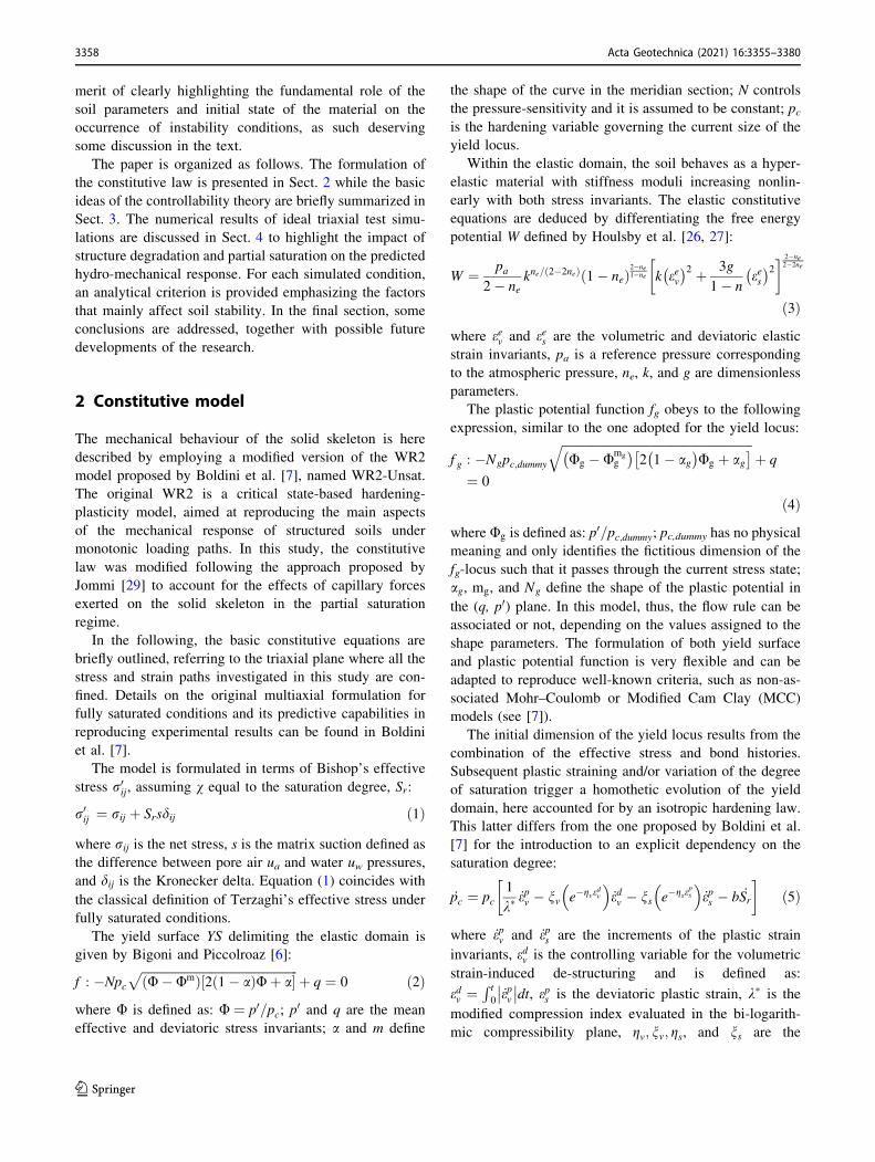
Unsaturated structured soils: constitutive modelling and stabilityanalyses
G. M. Rotisciani1 • A. Desideri1 • A. Amorosi1
Received: 15 December 2020 / Accepted: 12 July 2021 / Published online: 27 July 2021� The Author(s) 2021
AbstractThe paper presents a new single-surface elasto-plastic model for unsaturated cemented soils, formulated within the critical
state soil mechanics framework, which should be considered as an extension to unsaturated conditions of a recently
proposed constitutive law for saturated structured soils. The model has been developed with the main purpose of inspecting
the mechanical instabilities induced in natural soils by bond degradation resulting from the accumulation of plastic strains
and/or the changes in pore saturation. At this scope, the constitutive equations are used to simulate typical geotechnical
testing conditions, whose results are then analysed in light of the controllability theory. The results of triaxial tests on an
ideal fully saturated cemented soil and on the corresponding unsaturated uncemented one are first discussed, aiming at
detecting the evidence of potentially unstable conditions throughout the numerical simulations. This is followed by similar
analyses considering the combined effects of both the above features. For each analysed case, a simple analytical stability
criterion is proposed and validated against the numerical results, generalizing the results, and highlighting the crucial role
of state variables and model parameters on the possible occurrence of failure conditions.
Keywords Bond degradation � Constitutive modelling � Controllability � Material instability � Partial saturation
List of symbolsb Parameter controlling hydro-mechanical
coupling
Dij Components of hydro-mechanical stiffness
matrix
Drr Elasto-plastic mechanical stiffness matrix
Drw Coupling term of hydro-mechanical stiff-
ness matrix
Dwr Coupling term of hydro-mechanical stiff-
ness matrix
Dww Hydraulic term of hydro-mechanical stiff-
ness matrix
De Elastic stiffness matrix
Deij Components of elastic stiffness matrix
d Dilatancy
detXs Determinant of control matrix Xs
detXw Determinant of control matrix Xw
detXw,NORM Normalized determinant of control matrix
Xw
e Void ratio
_ew Water ratio increment
f Yield surface
fg Plastic potential function
g Parameter controlling nonlinear elasticity
H Hardening modulus
Hc Critical hardening modulus
k Parameter controlling nonlinear elasticity
M Slope of the critical state line in the stress
invariant plane
m Shape parameter of the yield locus
mg Shape parameter of the plastic potential
function
mw Shape parameter of Van Genuchten reten-
tion curve
N Parameter controlling pressure-sensitivity of
the yield locus
Ng Shape parameter of the plastic potential
function
& A. Amorosi
G. M. Rotisciani
A. Desideri
1 Dipartimento di Ingegneria Strutturale e Geotecnica,
Universita di Roma La Sapienza, Via Eudossiana 18,
00184 Rome, Italy
123
Acta Geotechnica (2021) 16:3355–3380https://doi.org/10.1007/s11440-021-01313-7(0123456789().,-volV)(0123456789().,- volV)
N0 Specific volume at p0 = 1 kPa under iso-
tropic conditions
n Porosity
ne Parameter controlling nonlinear elasticity
nw Shape parameter of Van Genuchten reten-
tion curve
(n/Sr)lim Threshold value of n/Sr for partially satu-
rated soils
(n/Sr)lim,s Threshold value of n/Sr for partially satu-
rated structured soils
pa Reference pressure for nonlinear elasticity
pc Isotropic yield compression pressure
pc,dummy Parameter controlling the dimension of the
fg-locus passing through the current stress
state
p0 Mean effective stress
_p Mean net stress increment_p0 Mean effective stress increment
q Deviatoric stress
_q Deviatoric stress increment
Rp Overconsolidation ratio
Sr Degree of saturation
Sr,res Residual degree of saturation_Sr Increment of degree of saturation
s Matrix suction
_s Rate of matrix suction
_s� Rate of smeared suction
ua Pore air pressure
uw Pore water pressure
_uw Rate of pore water pressure
W Free energy potential
d2W Second-order work per unit volume
X Constitutive control matrix
Xs Constitutive control matrix
Xw Constitutive control matrix
a Shape parameter of the yield locus
ag Shape parameter of the plastic potential
function
aw Shape parameter of Van Genuchten reten-
tion curve
dij Kronecker delta
ea Axial strain
es Deviatoric strain
ev Volumetric strain
edv Variable controlling volumetric strain-in-
duced de-structuring
ees Deviatoric elastic strain
eev Volumetric elastic strain
eps Deviatoric plastic strain
epv Volumetric plastic strain
_e Strain rate tensor
_es Deviatoric strain increment
_ev Volumetric strain increment
_eps Deviatoric plastic strain increment
_epv Volumetric plastic strain increment
g Stress ratio
gMAX Upper boundary of the loss of controllabil-
ity domain
gMIN Lower boundary of the loss of controlla-
bility domain
gs Deviatoric destructuration parameter
gv Volumetric destructuration parameter
k� Modified compression index
l Function of soil compressibility and
destructuration parameters
ns Deviatoric destructuration parameter
nv Volumetric destructuration parameter
rij Net stress
rij0 Bishop effective stress
_r Total stress rate tensor
_r� Incremental skeleton stress tensor
U Ratio between p0 and pcUg Ratio between p0 and pc,dummyv Bishop’s parameter
1 Introduction
Natural soils can be structured, according to Burland [10]
or Leroueil and Vaughan [37], and partially saturated. This
is the case of structured soils located near the ground
surface interacting with the atmosphere. The study of the
hydro-mechanical behaviour of these deposits is relevant to
many civil engineering applications, from the design of
shallow and deep foundations to the stability analysis of
slopes or road and railway embankments [4, 22, 64].
Despite the rather different origins, structure and partial
saturation share some similar mechanical effects as both
induce higher initial stiffness and strength which, at the
microstructural scale, should be qualitatively related to the
enhanced interparticle bonding due to cementation or
capillary menisci, respectively. In many geotechnical
boundary value problems, structure and partial saturation
might act separately or in combination, leading to a wide
range of different possible responses of the involved soil
deposit.
In structured soil deposits, the enhanced interparticle
bonding can be related to different processes as, for
example, percolation of calcium carbonate or weak lithi-
fication. As mentioned above, its main engineering effect is
the enhancement of the stiffness and strength of the soil.
3356 Acta Geotechnica (2021) 16:3355–3380
123
Qualitatively, it can be assumed that, upon application of
external loads, the stresses at certain interparticle contacts
attain the bond strength, triggering the mechanical bond
degradation (debonding) process. Bond degradation is an
irreversible phenomenon which, based on experimental
observations, results as mainly controlled by plastic strain
accumulation (e.g. [2, 3, 34, 48, 57]). It is characterized by
an initially more intense effect, which reduces with the
accumulation of plastic strains, bringing the material
towards its final fully destructured state.
In unsaturated soils, the capillary menisci existing at the
inter-granular contacts have a stabilizing effect, providing
an additional component of normal forces. Thus, the cap-
illary forces induce a sort of hydraulic bonding, whose
effects are similar to those activated by diagenetic bonds
[39, 63]. The experimental evidence shows that, starting
from saturated conditions, an increase in suction causes a
stiffening of the soil response and, in heavily over-con-
solidated soils, an increase in shear strength [66, 69].
Furthermore, under compression tests, the unsaturated
specimens are less compressible than the saturated ones,
exhibiting an increased apparent preconsolidation pressure.
Upon wetting, saturation degree increases and water
menisci progressively vanish, triggering a hydraulic
degradation process. Such a process is reversible and
mainly controlled by the changes in the degree of satura-
tion that can occur even for stress states within the elastic
domain [16, 18, 20, 72].
Despite the similar engineering effects induced by
cementation and partial saturation, remarkable differences
in the two phenomena exist. On one hand, cementation is
progressively damaged by plastic straining of the soil,
leading to a permanent and irreversible debonding process,
which, at the macroscale, reflects into a shrink of the elastic
domain in the stress space. Conversely, changes in the
degree of saturation due to either mechanical loads, rainfall
infiltration or evapotranspiration modify the capillary
bonds between particles, resulting into either a bonding-
like or debonding-like reversible process, which at the
macroscale corresponds to an expansion or a shrink of the
elastic domain, respectively.
In recent years, several constitutive models have been
proposed to describe the mechanical behaviour of natural
soils. Many of them are based on critical state soil
mechanics and are formulated within the single-surface
isotropic hardening-plasticity framework (e.g. [7, 34, 38]).
Their key ingredient is in the isotropic hardening rule,
which typically accounts for strain-induced structure
degradation by means of one or more negative exponential
damage-type terms. Along the same track, a further
improvement can be obtained accounting for early irre-
versibility, either by adopting a mixed isotropic-kinematic
hardening multi-surfaces formulation and/or by
implementing a bounding surface plasticity framework
(e.g. [5, 31, 47, 54, 60]).
At the same time, the increasing interest in unsaturated
soils has led to the formulation of numerous constitutive
models constructed extending those proposed for saturated
soils. Most of them are single-surface elasto-plastic models
(e.g. [1, 13, 19, 21, 25, 30, 33, 45, 56, 58, 59, 61, 67,
68, 71]); only limited attempts have been made to intro-
duce in the constitutive laws either bounding surface or
kinematic hardening concepts (e.g. [8, 23, 32, 55, 73]).
Some models are formulated in terms of two separate stress
variables [1, 19, 21, 30, 67, 68] while in others a single
stress variable is substituted for the saturated effective
stress [13, 33, 56, 58, 59, 61]. In this second case, some
modifications to the saturated hardening laws are required
to describe the effects of the partial saturation-induced
bonding [29].
Despite the above-mentioned considerable advances in
constitutive modelling, there are still few models able to
capture the combined effects of structure-related bonding
and partial saturation [9, 24, 36, 42, 46, 62, 70]. For this, in
the following, a relatively simple model accounting for
both structure degradation and partial saturation is pro-
posed. The model is formulated extending to unsaturated
conditions a recently proposed versatile constitutive for-
mulation for saturated structured soils [7]. The model aims
at reproducing the main features of the hydro-mechanical
response of unsaturated cemented soils under monotonic
loading conditions, adopting a single-surface isotropic
hardening elasto-plastic formulation based on a single
stress variable to account for partial saturation effects.
Similarly to the original model, the hardening laws
describing the destructuration phenomena can easily be
activated or deactivated depending on the observed
experimental response of the soil under study.
In the following, the effects of structure degradation and
partial saturation on the response of idealized natural soils
are numerically investigated adopting the proposed model,
separating first and then combining these two key features.
In the proposed element test simulations, particular
emphasis is placed on the failure conditions, with the aim
of investigating the stability of the material by detecting
the, so-called, loss of controllability domain. In fact, here
we interpret the occurrence of actual or potential instabil-
ities by means of the controllability theory, originally
proposed by Nova [43] and then extended in Buscarnera
and di Prisco [15], along the line of what discussed in
Buscarnera and Nova [11, 14], Buscarnera [11], Marinelli
and Buscarnera [40], Buscarnera and Dattola [12] and in
Rotisciani et al. [52]. Moreover, simple analytical criteria
for capturing soil instabilities are proposed and validated
against numerical results. Although these criteria only refer
to the proposed constitutive formulation, they have the
Acta Geotechnica (2021) 16:3355–3380 3357
123
merit of clearly highlighting the fundamental role of the
soil parameters and initial state of the material on the
occurrence of instability conditions, as such deserving
some discussion in the text.
The paper is organized as follows. The formulation of
the constitutive law is presented in Sect. 2 while the basic
ideas of the controllability theory are briefly summarized in
Sect. 3. The numerical results of ideal triaxial test simu-
lations are discussed in Sect. 4 to highlight the impact of
structure degradation and partial saturation on the predicted
hydro-mechanical response. For each simulated condition,
an analytical criterion is provided emphasizing the factors
that mainly affect soil stability. In the final section, some
conclusions are addressed, together with possible future
developments of the research.
2 Constitutive model
The mechanical behaviour of the solid skeleton is here
described by employing a modified version of the WR2
model proposed by Boldini et al. [7], named WR2-Unsat.
The original WR2 is a critical state-based hardening-
plasticity model, aimed at reproducing the main aspects
of the mechanical response of structured soils under
monotonic loading paths. In this study, the constitutive
law was modified following the approach proposed by
Jommi [29] to account for the effects of capillary forces
exerted on the solid skeleton in the partial saturation
regime.
In the following, the basic constitutive equations are
briefly outlined, referring to the triaxial plane where all the
stress and strain paths investigated in this study are con-
fined. Details on the original multiaxial formulation for
fully saturated conditions and its predictive capabilities in
reproducing experimental results can be found in Boldini
et al. [7].
The model is formulated in terms of Bishop’s effective
stress r0ij, assuming v equal to the saturation degree, Sr:
r0ij ¼ rij þ Srsdij ð1Þ
where rij is the net stress, s is the matrix suction defined as
the difference between pore air ua and water uw pressures,
and dij is the Kronecker delta. Equation (1) coincides with
the classical definition of Terzaghi’s effective stress under
fully saturated conditions.
The yield surface YS delimiting the elastic domain is
given by Bigoni and Piccolroaz [6]:
f : �Npcffiffiffiffiffiffiffiffiffiffiffiffiffiffiffiffiffiffiffiffiffiffiffiffiffiffiffiffiffiffiffiffiffiffiffiffiffiffiffiffiffiffiffiffiffiffiffiffiffiffiffi
U� Umð Þ 2 1� að ÞUþ a½ �p
þ q ¼ 0 ð2Þ
where U is defined as: U ¼ p0=pc; p0 and q are the mean
effective and deviatoric stress invariants; a and m define
the shape of the curve in the meridian section; N controls
the pressure-sensitivity and it is assumed to be constant; pcis the hardening variable governing the current size of the
yield locus.
Within the elastic domain, the soil behaves as a hyper-
elastic material with stiffness moduli increasing nonlin-
early with both stress invariants. The elastic constitutive
equations are deduced by differentiating the free energy
potential W defined by Houlsby et al. [26, 27]:
W ¼ pa2� ne
kne= 2�2neð Þ 1� neð Þ2�ne1�ne k eev
� �2 þ 3g
1� nees� �2
� �
2�ne2�2ne
ð3Þ
where eev and ees are the volumetric and deviatoric elastic
strain invariants, pa is a reference pressure corresponding
to the atmospheric pressure, ne, k, and g are dimensionless
parameters.
The plastic potential function fg obeys to the following
expression, similar to the one adopted for the yield locus:
f g : �Ngpc;dummy
ffiffiffiffiffiffiffiffiffiffiffiffiffiffiffiffiffiffiffiffiffiffiffiffiffiffiffiffiffiffiffiffiffiffiffiffiffiffiffiffiffiffiffiffiffiffiffiffiffiffiffiffiffiffiffiffiffiffiffiffiffiffi
Ug � Umg
g
� �
2 1� ag� �
Ug þ ag� �
q
þ q
¼ 0
ð4Þ
where Ug is defined as: p0=pc;dummy; pc,dummy has no physical
meaning and only identifies the fictitious dimension of the
fg-locus such that it passes through the current stress state;
ag, mg, and Ng define the shape of the plastic potential in
the (q, p0) plane. In this model, thus, the flow rule can be
associated or not, depending on the values assigned to the
shape parameters. The formulation of both yield surface
and plastic potential function is very flexible and can be
adapted to reproduce well-known criteria, such as non-as-
sociated Mohr–Coulomb or Modified Cam Clay (MCC)
models (see [7]).
The initial dimension of the yield locus results from the
combination of the effective stress and bond histories.
Subsequent plastic straining and/or variation of the degree
of saturation trigger a homothetic evolution of the yield
domain, here accounted for by an isotropic hardening law.
This latter differs from the one proposed by Boldini et al.
[7] for the introduction to an explicit dependency on the
saturation degree:
_pc ¼ pc1
k�_epv � nv e�gve
dv
_edv � ns e�gseps
_eps � b _Sr
� �
ð5Þ
where _epv and _eps are the increments of the plastic strain
invariants, edv is the controlling variable for the volumetric
strain-induced de-structuring and is defined as:
edv ¼R t
0_epv�
�
�
�dt, eps is the deviatoric plastic strain, k� is the
modified compression index evaluated in the bi-logarith-
mic compressibility plane, gv; nv; gs, and ns are the
3358 Acta Geotechnica (2021) 16:3355–3380
123
volumetric and deviatoric destructuration parameters, _Sr is
the increment in the saturation degree and b defines the
relative position on the normal compression line (NCL)
related to the current Sr with respect to the saturated one.
In Eq. (5), the first term coincides with the hardening
law of the MCC model for saturated soils expressed as a
function of the modified compression index. The second
and third terms describe the strain-induced structure
degradation using two separate negative exponential dam-
age-type forms. The last term represents the simplest form
of the hydraulic hardening that allows capturing most of
the observed phenomena for unsaturated soils as, for
example, the increase of the preconsolidation pressure with
suction, and the wetting-induced collapse [17, 35, 49, 51].
It worth noting that this expression is valid only when Sr is
not far from the unity and water menisci are homoge-
neously distributed over the soil volume [13], as assumed
in the following.
The modelling strategy employed for capturing
hydraulic bonding effects is similar to that used in
cemented soils. This choice is justified by the similarities
observed experimentally between the mechanical beha-
viour of unsaturated and bonded soils. In this framework,
the mechanical bond degradation is an irreversible process
controlled by plastic strain accumulation, whose intensity
exponentially decreases with the development of the plastic
strains. Instead, the hydraulic bonding is a reversible pro-
cess controlled by the changes in degree of saturation,
which is considered as a measure of the overall distribution
of the capillary forces responsible for the hydraulic
bonding.
In this model, the effects of saturation and cementation
are uncoupled. This is of course a simplification of the real
soil behaviour and may represent a limitation in terms of
predictive capabilities of the model when applied to those
soils in which the above coupling plays a non-negligible
role, as, for example, the weakly bonded unsaturated
sapriolite discussed in [36].
The expression suggested by Van Genuchten [65] is
adopted for describing the soil water retention curve
(WRC):
Sr ¼ Sr;res þ 1� Sr;res� �
= 1þ awsð Þnw½ �mw ð6Þ
where aw is linked to the air-entry value, nw and mw control
the shape of the curve, and Sr,res is the residual saturation
degree. For the sake of simplicity, suction is assumed to be
a unique function of the degree of saturation, neglecting
both hydraulic hysteresis and the dependence on the cur-
rent void ratio.
The retention model given by Eq. (6) can be reformu-
lated in a more convenient way for the analysis of the
possible occurrence of instabilities as follows:
_s� ¼ nos
oSr_Sr ð7Þ
where _s� is the incremental hydraulic stress variable con-
jugate to _Sr in the definition of the second-order work d2W,
_s� ¼ n _s [15], n is the porosity and _s is the increment of
matrix suction.
3 Controllability theory
Material stability is here discussed with reference to the
controllability theory proposed by Nova [43]. This theory
combines the Hill’s stability criterion with the concept of
test controllability and demonstrates that the crucial factor
determining the occurrence of instability is the way in
which the perturbation is actually imposed to the specimen
[28, 43].
According to the Hill’s criterion, positive values of the
second-order work d2W under any imposed strain incre-
ment guarantee the stability of the material response. Null
or negative values reveal, instead, a latent instability, not
necessarily related to the occurrence of an uncontrolled
deformation process. More notably, the evidence of
d2W B 0 points out the existence of at least one loading
program under which the control of the incremental
response is lost: instability takes place when the imposed
loading program exactly coincides with the one along
which the control is lost.
According to Nova [43], the loss of both uniqueness and
existence of the incremental response occurs when:
detX ¼ 0 ð8Þ
where X is the control matrix linking the control variables
to the response ones. The condition for the loss of con-
trollability (Eq. (8)) corresponds to the vanishing of
d2W [43].
Beyond inspecting the stability under the experimentally
adopted set of control variables, this theory can be
employed to track the susceptibility of the material to
specific modes of failure and to identify the conditions for
their activation [41]. This strategy, known as latent insta-
bility analysis, requires the definition of control matrixes
corresponding to sets of control variables different from
those actually imposed in a test, and the monitoring of their
determinant. This approach allows to inspect the conse-
quences on soil stability of possible changes in static-
kinematic constrains.
In this study, the above strategy is employed for
investigating failure in both hardening and softening
regimes for fully and partially saturated soils. For this
purpose, the control matrixes Xs and Xw were defined and
monitored in the numerical simulations, the first one being
Acta Geotechnica (2021) 16:3355–3380 3359
123
checked in drained/suction-controlled tests, whereas the
second in undrained/constant water content tests.
Xs is the hydro-mechanical stiffness matrix that links the
control variables _r� and _s� to the response variables _e and_Sr:
_r�
_s�
� �
¼ Drr Drw
Dwr Dww
� �
_e� _Sr
� �
ð9Þ
where _e is the principal strain rate vector, _r� is the principalstress measure conjugate to _e in the definition of d2W,
defined as: _r�i ¼ _ri þ Sr _s, Drr is the mechanical elasto-
plastic stiffness matrix defined as:
Drr ¼ De � 1
H þ HcDe og
or0
� �
� of
or0De
� �
ð10Þ
where De is the elastic stiffness matrix, of=or0 and og=or0
are the partial derivatives of the yield surface and plastic
potential function with respect to r0, H is the hardening
modulus:
H ¼ � of
opc
opcoεp
og
or0ð11Þ
and Hc is the critical hardening modulus:
Hc ¼of
or0� De og
or0ð12Þ
Dwr is a null vector since the WRC is assumed to be
independent of void ratio; Dww is a scalar term resulting
from the Van Genuchten expression and Drw describes the
mechanical effects induced by changes in Sr:
Drw ¼ � 1
H þ Hc
of
opcbpc
�
� De og
or0ð13Þ
where of=opc is the partial derivative of the yield surface
with respect to pc.
Under drained conditions, Xs coincides with the
mechanical elasto-plastic stiffness matrix, and the vanish-
ing of its determinant points out the attainment of shear
failure.
Xw can be derived from Eq. (9) assuming as control
variables the total stress increments _r and the variations in
water content _ew= 1þ eð Þ, and as response variables _e and
_s:
_r
� _ew1þ e
" #
¼ Xw½ � _e_s
� �
ð14Þ
By monitoring the determinant of Xw, the occurrence of
potential instabilities due to, for example, volumetric col-
lapse, static liquefaction or undrained shear failure can be
captured. Under fully saturated conditions, Xw is given by:
Xw ¼ Drr 1
1 0
� �
ð15Þ
4 Stability analyses under axisymmetricloading paths
In this section, the material response is analysed under the
usual geotechnical testing conditions along axisymmetric
loading paths. A series of compression triaxial tests was
numerically simulated using the commercial finite element
code Abaqus/Standard, where the proposed model was
implemented adopting an explicit integration scheme with
automatic sub-stepping and error control, modifying the
Fortran 90 routines developed by Boldini et al. [7] for its
fully saturated version.
The ideal tests were carried out on a single eight-node
axisymmetric element (denoted as CAX8P in the Abaqus
code) keeping the suction constant (corresponding to
drained conditions for fully saturated soils) or preventing
water outflow (corresponding to undrained conditions for
fully saturated soils). The simulations were run controlling
the axial strain and radial stress. Such mixed stress–strain
control guarantees the stability of the soil response along
the entire loading path, preventing the development of any
instability phenomenon which, conversely, can occur under
stress-controlled test conditions. In the mixed control
numerical tests illustrated in the following, potential
instability conditions can be captured by monitoring the
determinant of the appropriate control matrixes, i.e. Xs and
Xw, depending on the imposed hydraulic boundary
conditions.
All the simulations were carried out by the WR2-Unsat
model illustrated in Sect. 2. This model relies on a flexible
and hierarchical formulation suitable for describing soil
instabilities caused by non-associated flow rule, structure
degradation induced by the accumulation of plastic strains
and the changes in pore saturation. This study focuses on
the effects on soil stability of the last two factors, assuming
for the sake of simplicity an associated flow rule
throughout the whole set of numerical experiments. Details
on the role of non-associated conditions on the stability of
saturated granular media can be found in Nova [44]. In this
section, the effects of structure degradation and partial
saturation are first inspected separately and then combined,
to mimic more realistically the state of many natural soils.
The set of hydro-mechanical constitutive parameters
used in the numerical simulations is summarized in
Table 1. The considered material is an ideal fine-grained
soil characterized by low plasticity (see [7, 50]), whose
hydro-mechanical properties were selected to emphasize
3360 Acta Geotechnica (2021) 16:3355–3380
123
the instability phenomena triggered by the loss of structure
and suction.
The study was conducted by employing a relatively
simple version of the WR2-Unsat model, characterized by
the classical MCC yield surface (a = 1, m = 2, N = M,
where M is the slope of the critical state line in the p0 andq plane), an associated flow rule (ag = a, mg = m, Ng-
= N) and possible structure degradation. The adopted
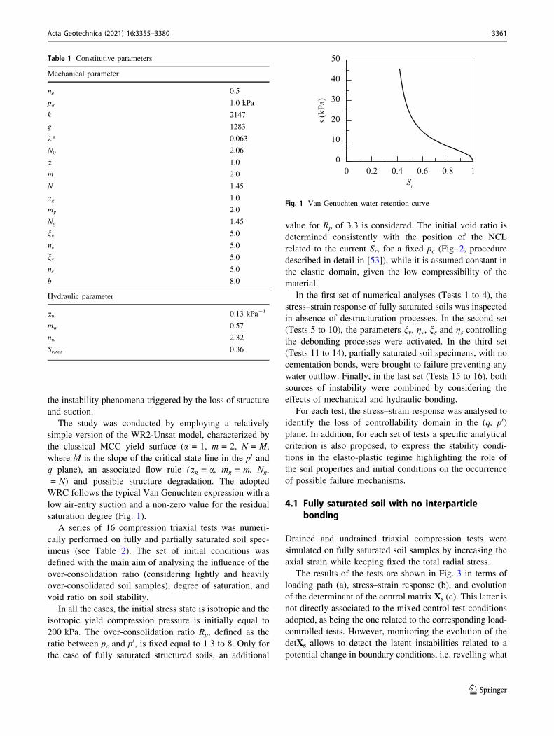
WRC follows the typical Van Genuchten expression with a
low air-entry suction and a non-zero value for the residual
saturation degree (Fig. 1).
A series of 16 compression triaxial tests was numeri-
cally performed on fully and partially saturated soil spec-
imens (see Table 2). The set of initial conditions was
defined with the main aim of analysing the influence of the
over-consolidation ratio (considering lightly and heavily
over-consolidated soil samples), degree of saturation, and
void ratio on soil stability.
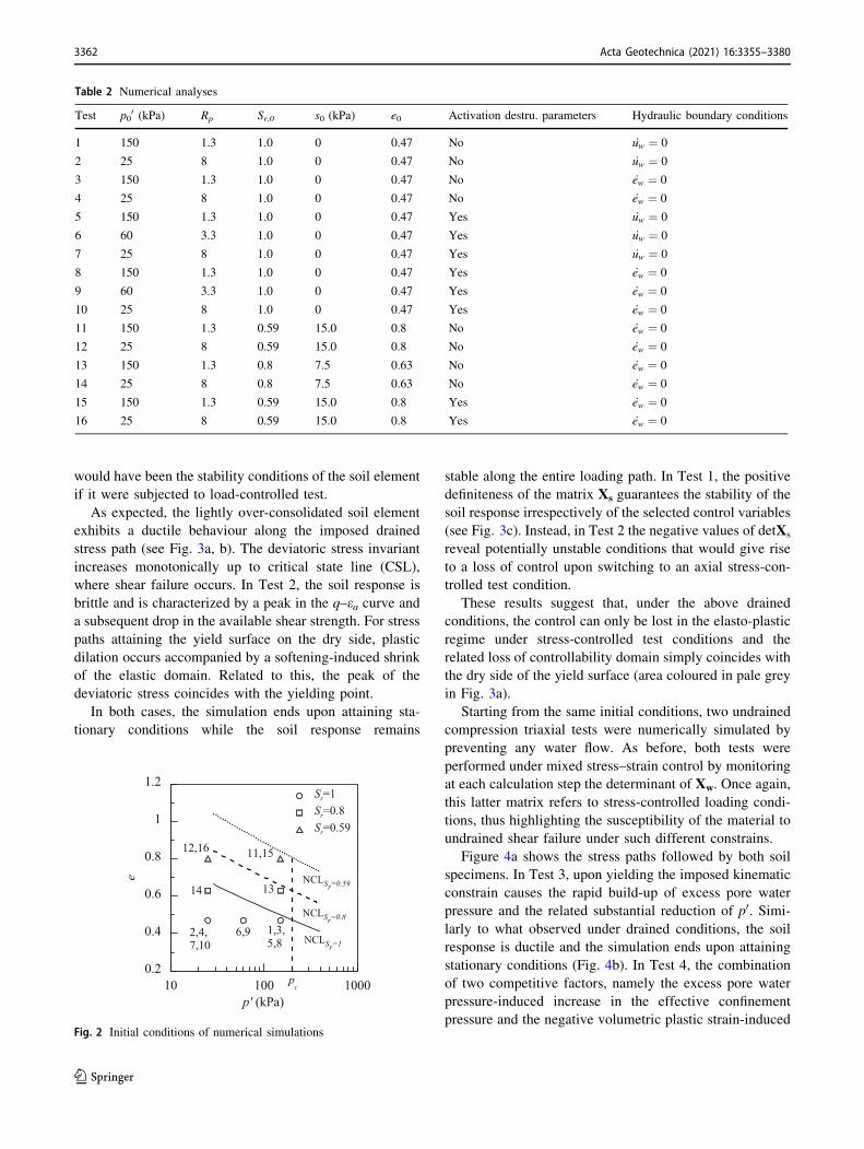
In all the cases, the initial stress state is isotropic and the
isotropic yield compression pressure is initially equal to
200 kPa. The over-consolidation ratio Rp, defined as the
ratio between pc and p0, is fixed equal to 1.3 to 8. Only for
the case of fully saturated structured soils, an additional
value for Rp of 3.3 is considered. The initial void ratio is
determined consistently with the position of the NCL
related to the current Sr, for a fixed pc (Fig. 2, procedure
described in detail in [53]), while it is assumed constant in
the elastic domain, given the low compressibility of the
material.
In the first set of numerical analyses (Tests 1 to 4), the
stress–strain response of fully saturated soils was inspected
in absence of destructuration processes. In the second set
(Tests 5 to 10), the parameters nv, gv, ns and gs controllingthe debonding processes were activated. In the third set
(Tests 11 to 14), partially saturated soil specimens, with no
cementation bonds, were brought to failure preventing any
water outflow. Finally, in the last set (Tests 15 to 16), both
sources of instability were combined by considering the
effects of mechanical and hydraulic bonding.
For each test, the stress–strain response was analysed to
identify the loss of controllability domain in the (q, p0)plane. In addition, for each set of tests a specific analytical
criterion is also proposed, to express the stability condi-
tions in the elasto-plastic regime highlighting the role of
the soil properties and initial conditions on the occurrence
of possible failure mechanisms.
4.1 Fully saturated soil with no interparticlebonding
Drained and undrained triaxial compression tests were
simulated on fully saturated soil samples by increasing the
axial strain while keeping fixed the total radial stress.
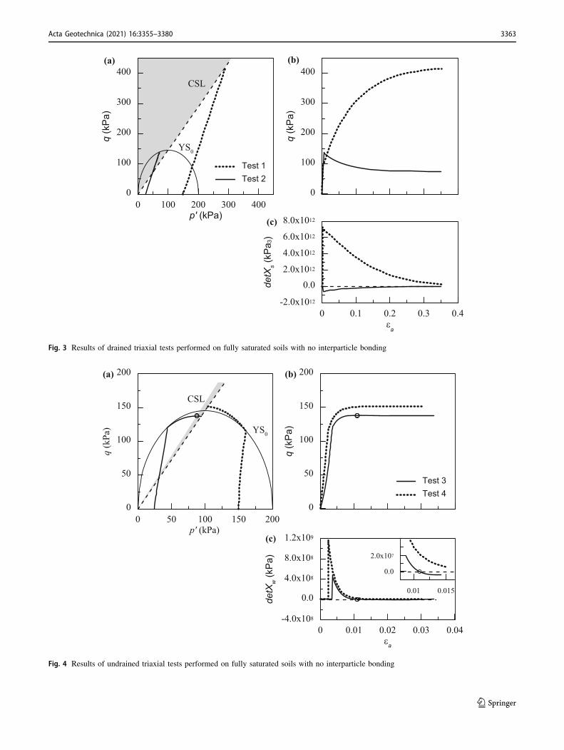
The results of the tests are shown in Fig. 3 in terms of
loading path (a), stress–strain response (b), and evolution
of the determinant of the control matrix Xs (c). This latter is
not directly associated to the mixed control test conditions
adopted, as being the one related to the corresponding load-
controlled tests. However, monitoring the evolution of the
detXs allows to detect the latent instabilities related to a
potential change in boundary conditions, i.e. revelling what
Table 1 Constitutive parameters
Mechanical parameter
ne 0.5
pa 1.0 kPa
k 2147
g 1283
k* 0.063
N0 2.06
a 1.0
m 2.0
N 1.45
ag 1.0
mg 2.0
Ng 1.45
nv 5.0
gv 5.0
ns 5.0
gs 5.0
b 8.0
Hydraulic parameter
aw 0.13 kPa-1
mw 0.57
nw 2.32
Sr,res 0.36
0 0.2 0.4 0.6 0.8 1Sr
0
10
20
30
40
50
s (kP
a)
Fig. 1 Van Genuchten water retention curve
Acta Geotechnica (2021) 16:3355–3380 3361
123
would have been the stability conditions of the soil element
if it were subjected to load-controlled test.
As expected, the lightly over-consolidated soil element
exhibits a ductile behaviour along the imposed drained
stress path (see Fig. 3a, b). The deviatoric stress invariant
increases monotonically up to critical state line (CSL),
where shear failure occurs. In Test 2, the soil response is
brittle and is characterized by a peak in the q–ea curve anda subsequent drop in the available shear strength. For stress
paths attaining the yield surface on the dry side, plastic
dilation occurs accompanied by a softening-induced shrink
of the elastic domain. Related to this, the peak of the
deviatoric stress coincides with the yielding point.
In both cases, the simulation ends upon attaining sta-
tionary conditions while the soil response remains
stable along the entire loading path. In Test 1, the positive
definiteness of the matrix Xs guarantees the stability of the
soil response irrespectively of the selected control variables
(see Fig. 3c). Instead, in Test 2 the negative values of detXs
reveal potentially unstable conditions that would give rise
to a loss of control upon switching to an axial stress-con-
trolled test condition.
These results suggest that, under the above drained
conditions, the control can only be lost in the elasto-plastic
regime under stress-controlled test conditions and the
related loss of controllability domain simply coincides with
the dry side of the yield surface (area coloured in pale grey
in Fig. 3a).
Starting from the same initial conditions, two undrained
compression triaxial tests were numerically simulated by
preventing any water flow. As before, both tests were
performed under mixed stress–strain control by monitoring
at each calculation step the determinant of Xw. Once again,
this latter matrix refers to stress-controlled loading condi-
tions, thus highlighting the susceptibility of the material to
undrained shear failure under such different constrains.
Figure 4a shows the stress paths followed by both soil
specimens. In Test 3, upon yielding the imposed kinematic
constrain causes the rapid build-up of excess pore water
pressure and the related substantial reduction of p0. Simi-
larly to what observed under drained conditions, the soil
response is ductile and the simulation ends upon attaining
stationary conditions (Fig. 4b). In Test 4, the combination
of two competitive factors, namely the excess pore water
pressure-induced increase in the effective confinement
pressure and the negative volumetric plastic strain-induced
Table 2 Numerical analyses
Test p00 (kPa) Rp Sr,0 s0 (kPa) e0 Activation destru. parameters Hydraulic boundary conditions
1 150 1.3 1.0 0 0.47 No _uw ¼ 0
2 25 8 1.0 0 0.47 No _uw ¼ 0
3 150 1.3 1.0 0 0.47 No _ew ¼ 0
4 25 8 1.0 0 0.47 No _ew ¼ 0
5 150 1.3 1.0 0 0.47 Yes _uw ¼ 0
6 60 3.3 1.0 0 0.47 Yes _uw ¼ 0
7 25 8 1.0 0 0.47 Yes _uw ¼ 0
8 150 1.3 1.0 0 0.47 Yes _ew ¼ 0
9 60 3.3 1.0 0 0.47 Yes _ew ¼ 0
10 25 8 1.0 0 0.47 Yes _ew ¼ 0
11 150 1.3 0.59 15.0 0.8 No _ew ¼ 0
12 25 8 0.59 15.0 0.8 No _ew ¼ 0
13 150 1.3 0.8 7.5 0.63 No _ew ¼ 0
14 25 8 0.8 7.5 0.63 No _ew ¼ 0
15 150 1.3 0.59 15.0 0.8 Yes _ew ¼ 0
16 25 8 0.59 15.0 0.8 Yes _ew ¼ 0
10 100 1000p' (kPa)
0.2
0.4
0.6
0.8
1
1.2
e
Sr=1Sr=0.8Sr=0.59
NCLSr=1
NCLSr=0.8
NCLSr=0.59
1,3,5,8
2,4,7,10
6,9
11,1512,16
1314
pc
Fig. 2 Initial conditions of numerical simulations
3362 Acta Geotechnica (2021) 16:3355–3380
123
0 100 200 300 400p' (kPa)
0
100
200
300
400
q (k
Pa)
0 0.1 0.2 0.3 0.4εa
-2.0x10¹²
0.02.0x1012
4.0x10¹²
6.0x10¹²
8.0x10¹²
detX
s(k
Pa 3
)
Test 1Test 2
0
100
200
300
400
q (k
Pa)
(a) (b)
(c)
YS0
CSL
Fig. 3 Results of drained triaxial tests performed on fully saturated soils with no interparticle bonding
0 50 100 150 200p' (kPa)
0
50
100
150
200
q (k
Pa)
0 0.01 0.02 0.03 0.04εa
-4.0x10⁸
0.0
4.0x10⁸
8.0x10⁸
1.2x10⁹
detX
w(k
Pa)
Test 3Test 4
0
50
100
150
200
q (k
Pa)
(a) (b)
(c)
YS0
CSL
0.01 0.015
0.0
2.0x10⁷
Fig. 4 Results of undrained triaxial tests performed on fully saturated soils with no interparticle bonding
Acta Geotechnica (2021) 16:3355–3380 3363
123
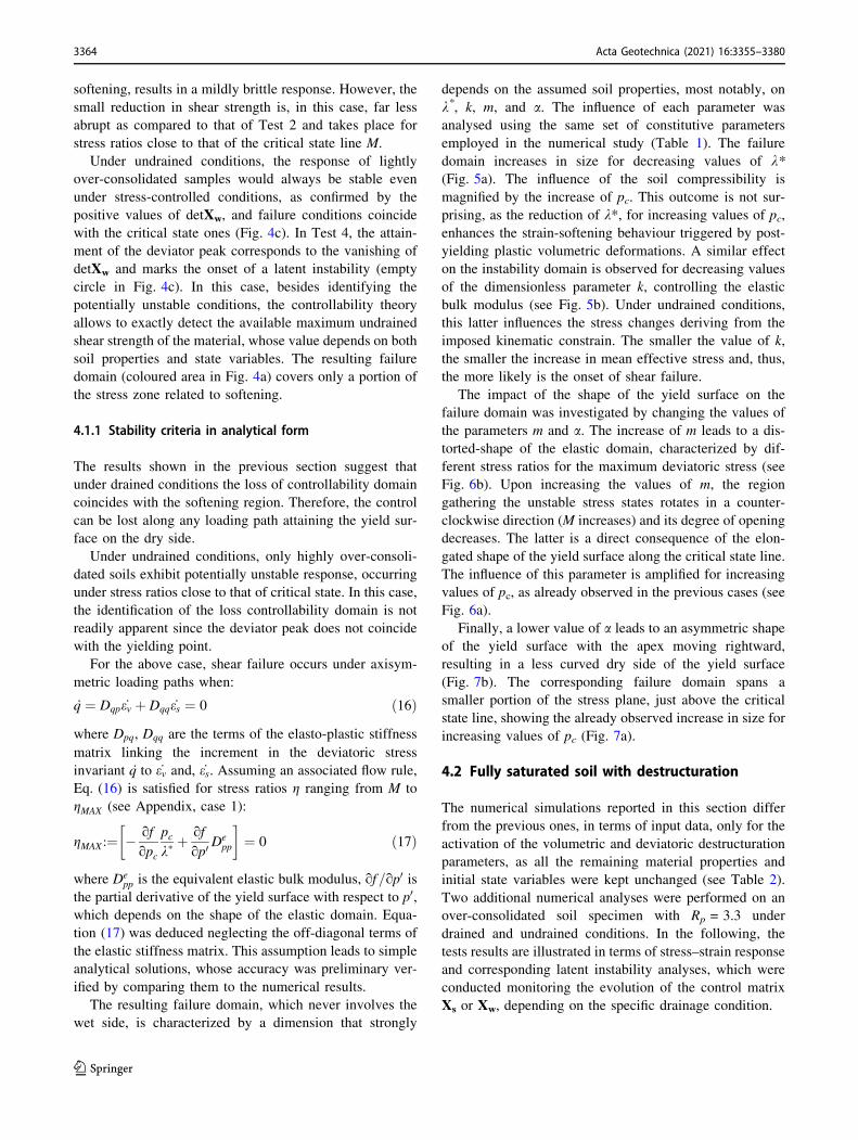
softening, results in a mildly brittle response. However, the
small reduction in shear strength is, in this case, far less
abrupt as compared to that of Test 2 and takes place for
stress ratios close to that of the critical state line M.
Under undrained conditions, the response of lightly
over-consolidated samples would always be stable even
under stress-controlled conditions, as confirmed by the
positive values of detXw, and failure conditions coincide
with the critical state ones (Fig. 4c). In Test 4, the attain-
ment of the deviator peak corresponds to the vanishing of
detXw and marks the onset of a latent instability (empty
circle in Fig. 4c). In this case, besides identifying the
potentially unstable conditions, the controllability theory
allows to exactly detect the available maximum undrained
shear strength of the material, whose value depends on both
soil properties and state variables. The resulting failure
domain (coloured area in Fig. 4a) covers only a portion of
the stress zone related to softening.
4.1.1 Stability criteria in analytical form
The results shown in the previous section suggest that
under drained conditions the loss of controllability domain
coincides with the softening region. Therefore, the control
can be lost along any loading path attaining the yield sur-
face on the dry side.
Under undrained conditions, only highly over-consoli-
dated soils exhibit potentially unstable response, occurring
under stress ratios close to that of critical state. In this case,
the identification of the loss controllability domain is not
readily apparent since the deviator peak does not coincide
with the yielding point.
For the above case, shear failure occurs under axisym-
metric loading paths when:
_q ¼ Dqp _ev þ Dqq _es ¼ 0 ð16Þ
where Dpq, Dqq are the terms of the elasto-plastic stiffness
matrix linking the increment in the deviatoric stress
invariant _q to _ev and, _es. Assuming an associated flow rule,
Eq. (16) is satisfied for stress ratios g ranging from M to
gMAX (see Appendix, case 1):
gMAX :¼ � of
opc
pck�
þ of
op0De
pp
� �
¼ 0 ð17Þ
where Depp is the equivalent elastic bulk modulus, of=op0 is
the partial derivative of the yield surface with respect to p0,which depends on the shape of the elastic domain. Equa-
tion (17) was deduced neglecting the off-diagonal terms of
the elastic stiffness matrix. This assumption leads to simple
analytical solutions, whose accuracy was preliminary ver-
ified by comparing them to the numerical results.
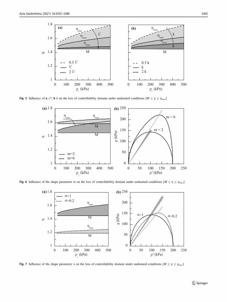
The resulting failure domain, which never involves the
wet side, is characterized by a dimension that strongly
depends on the assumed soil properties, most notably, on
k*, k, m, and a. The influence of each parameter was
analysed using the same set of constitutive parameters
employed in the numerical study (Table 1). The failure
domain increases in size for decreasing values of k*(Fig. 5a). The influence of the soil compressibility is
magnified by the increase of pc. This outcome is not sur-
prising, as the reduction of k*, for increasing values of pc,
enhances the strain-softening behaviour triggered by post-
yielding plastic volumetric deformations. A similar effect
on the instability domain is observed for decreasing values
of the dimensionless parameter k, controlling the elastic
bulk modulus (see Fig. 5b). Under undrained conditions,
this latter influences the stress changes deriving from the
imposed kinematic constrain. The smaller the value of k,
the smaller the increase in mean effective stress and, thus,
the more likely is the onset of shear failure.
The impact of the shape of the yield surface on the
failure domain was investigated by changing the values of
the parameters m and a. The increase of m leads to a dis-
torted-shape of the elastic domain, characterized by dif-
ferent stress ratios for the maximum deviatoric stress (see
Fig. 6b). Upon increasing the values of m, the region
gathering the unstable stress states rotates in a counter-
clockwise direction (M increases) and its degree of opening
decreases. The latter is a direct consequence of the elon-
gated shape of the yield surface along the critical state line.
The influence of this parameter is amplified for increasing
values of pc, as already observed in the previous cases (see
Fig. 6a).
Finally, a lower value of a leads to an asymmetric shape
of the yield surface with the apex moving rightward,
resulting in a less curved dry side of the yield surface
(Fig. 7b). The corresponding failure domain spans a
smaller portion of the stress plane, just above the critical
state line, showing the already observed increase in size for
increasing values of pc (Fig. 7a).
4.2 Fully saturated soil with destructuration
The numerical simulations reported in this section differ
from the previous ones, in terms of input data, only for the
activation of the volumetric and deviatoric destructuration
parameters, as all the remaining material properties and
initial state variables were kept unchanged (see Table 2).
Two additional numerical analyses were performed on an
over-consolidated soil specimen with Rp = 3.3 under
drained and undrained conditions. In the following, the
tests results are illustrated in terms of stress–strain response
and corresponding latent instability analyses, which were
conducted monitoring the evolution of the control matrix
Xs or Xw, depending on the specific drainage condition.
3364 Acta Geotechnica (2021) 16:3355–3380
123
0 100 200 300 400 500p
c (kPa)
1
1.2
1.4
1.6
1.8
η
0.5 λ*
λ*
2 λ*
ηmax
ηmax
ηmax
0 100 200 300 400 500p
c (kPa)
0.5 kk2 k
(b)(a)
λ*
M
ηmax
ηmaxη
max
k
M
Fig. 5 Influence of a k*, b k on the loss of controllability domain under undrained conditions [M B g B gmax]
0 100 200 300 400 500pc (kPa)
1
1.2
1.4
1.6
1.8
η
m=2m=6
0 50 100 150 200 250p' (kPa)
0
50
100
150
200
250
q (k
Pa) m = 2
m = 6
(a) (b)
M
M
ηmax
ηmax
Fig. 6 Influence of the shape parameter m on the loss of controllability domain under undrained conditions [M B g B gmax]
0 100 200 300 400 500p
c (kPa)
1
1.2
1.4
1.6
1.8
η
α=1α=0.2
0 50 100 150 200 250p' (kPa)
0
50
100
150
200
250
q (k
Pa) α=1 α=0.2
(a) (b)
M
M
ηmax
ηmax
Fig. 7 Influence of the shape parameter a on the loss of controllability domain under undrained conditions [M B g B gmax]
Acta Geotechnica (2021) 16:3355–3380 3365
123
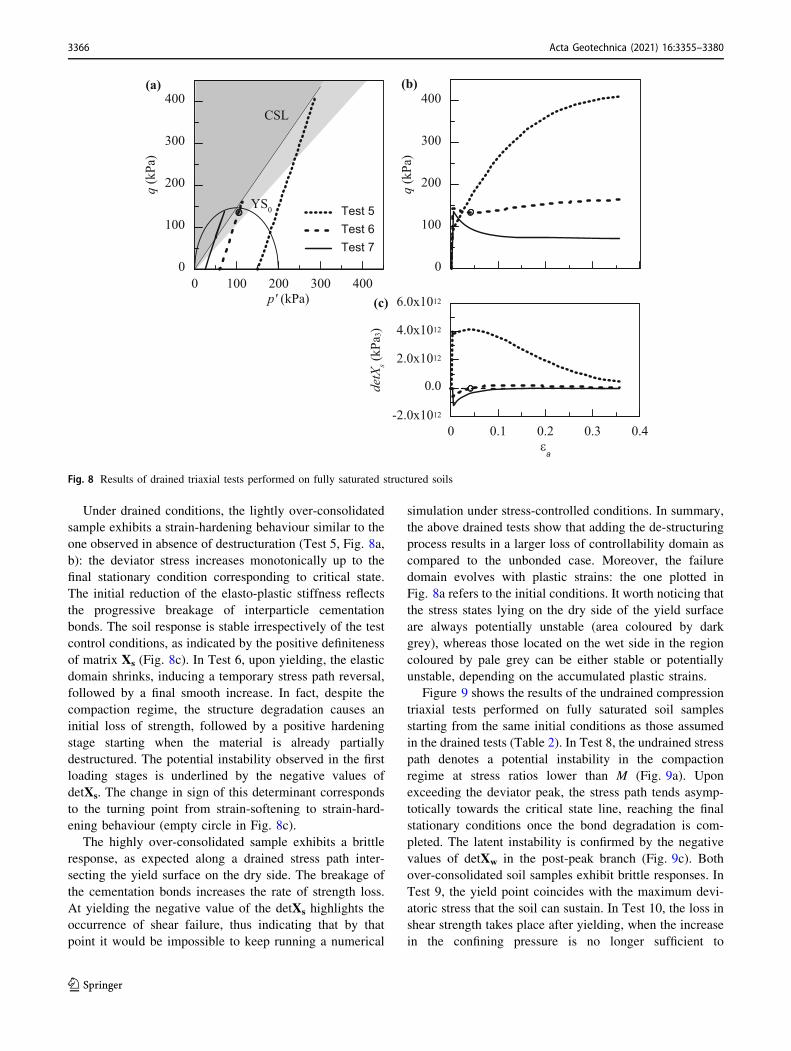
Under drained conditions, the lightly over-consolidated
sample exhibits a strain-hardening behaviour similar to the
one observed in absence of destructuration (Test 5, Fig. 8a,
b): the deviator stress increases monotonically up to the
final stationary condition corresponding to critical state.
The initial reduction of the elasto-plastic stiffness reflects
the progressive breakage of interparticle cementation
bonds. The soil response is stable irrespectively of the test
control conditions, as indicated by the positive definiteness
of matrix Xs (Fig. 8c). In Test 6, upon yielding, the elastic
domain shrinks, inducing a temporary stress path reversal,
followed by a final smooth increase. In fact, despite the
compaction regime, the structure degradation causes an
initial loss of strength, followed by a positive hardening
stage starting when the material is already partially
destructured. The potential instability observed in the first
loading stages is underlined by the negative values of
detXs. The change in sign of this determinant corresponds
to the turning point from strain-softening to strain-hard-
ening behaviour (empty circle in Fig. 8c).
The highly over-consolidated sample exhibits a brittle
response, as expected along a drained stress path inter-
secting the yield surface on the dry side. The breakage of
the cementation bonds increases the rate of strength loss.
At yielding the negative value of the detXs highlights the
occurrence of shear failure, thus indicating that by that
point it would be impossible to keep running a numerical
simulation under stress-controlled conditions. In summary,
the above drained tests show that adding the de-structuring
process results in a larger loss of controllability domain as
compared to the unbonded case. Moreover, the failure
domain evolves with plastic strains: the one plotted in
Fig. 8a refers to the initial conditions. It worth noticing that
the stress states lying on the dry side of the yield surface
are always potentially unstable (area coloured by dark
grey), whereas those located on the wet side in the region
coloured by pale grey can be either stable or potentially
unstable, depending on the accumulated plastic strains.
Figure 9 shows the results of the undrained compression
triaxial tests performed on fully saturated soil samples
starting from the same initial conditions as those assumed
in the drained tests (Table 2). In Test 8, the undrained stress
path denotes a potential instability in the compaction
regime at stress ratios lower than M (Fig. 9a). Upon
exceeding the deviator peak, the stress path tends asymp-
totically towards the critical state line, reaching the final
stationary conditions once the bond degradation is com-
pleted. The latent instability is confirmed by the negative
values of detXw in the post-peak branch (Fig. 9c). Both
over-consolidated soil samples exhibit brittle responses. In
Test 9, the yield point coincides with the maximum devi-
atoric stress that the soil can sustain. In Test 10, the loss in
shear strength takes place after yielding, when the increase
in the confining pressure is no longer sufficient to
0 100 200 300 400p' (kPa)
0
100
200
300
400
q (k
Pa)
0 0.1 0.2 0.3 0.4εa
-2.0x10¹²
0.0
2.0x10¹²
4.0x10¹²
6.0x10¹²
detX
s(k
Pa3)
Test 5Test 6Test 7
0
100
200
300
400
q (k
Pa)
(a) (b)
(c)
YS0
CSL
Fig. 8 Results of drained triaxial tests performed on fully saturated structured soils
3366 Acta Geotechnica (2021) 16:3355–3380
123
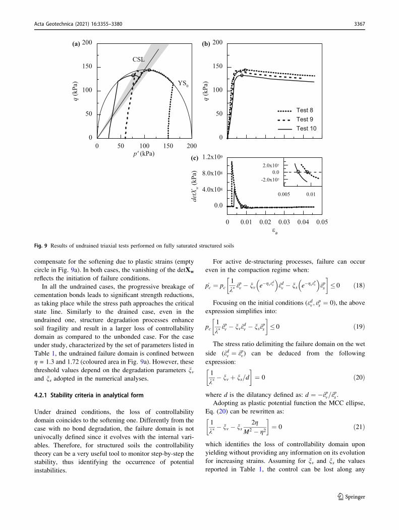
compensate for the softening due to plastic strains (empty
circle in Fig. 9a). In both cases, the vanishing of the detXw
reflects the initiation of failure conditions.
In all the undrained cases, the progressive breakage of
cementation bonds leads to significant strength reductions,
as taking place while the stress path approaches the critical
state line. Similarly to the drained case, even in the
undrained one, structure degradation processes enhance
soil fragility and result in a larger loss of controllability
domain as compared to the unbonded case. For the case
under study, characterized by the set of parameters listed in
Table 1, the undrained failure domain is confined between
g = 1.3 and 1.72 (coloured area in Fig. 9a). However, these
threshold values depend on the degradation parameters nvand ns adopted in the numerical analyses.
4.2.1 Stability criteria in analytical form
Under drained conditions, the loss of controllability
domain coincides to the softening one. Differently from the
case with no bond degradation, the failure domain is not
univocally defined since it evolves with the internal vari-
ables. Therefore, for structured soils the controllability
theory can be a very useful tool to monitor step-by-step the
stability, thus identifying the occurrence of potential
instabilities.
For active de-structuring processes, failure can occur
even in the compaction regime when:
_pc ¼ pc1
k�_epv � nv e�gve
dv
_edv � ns e�gseps
_eps
� �
� 0 ð18Þ
Focusing on the initial conditions (edv ; eps ¼ 0), the above
expression simplifies into:
pc1
k�_epv � nv _e
dv � ns _e
ps
� �
� 0 ð19Þ
The stress ratio delimiting the failure domain on the wet
side ( _edv ¼ _epv) can be deduced from the following
expression:
1
k�� nv þ ns=d
� �
¼ 0 ð20Þ
where d is the dilatancy defined as: d ¼ � _epv= _eps .
Adopting as plastic potential function the MCC ellipse,
Eq. (20) can be rewritten as:
1
k�� nv � ns
2g
M2 � g2
� �
¼ 0 ð21Þ
which identifies the loss of controllability domain upon
yielding without providing any information on its evolution
for increasing strains. Assuming for nv and ns the values
reported in Table 1, the control can be lost along any
0 50 100 150 200p' (kPa)
0
50
100
150
200
q (k
Pa)
0 0.01 0.02 0.03 0.04 0.05εa
0.0
4.0x10⁸
8.0x10⁸
1.2x10⁹
detX
w(k
Pa)
Test 8Test 9Test 10
0
50
100
150
200
q (k
Pa)
(a) (b)
(c)
YS0
CSL
0.005 0.01
-2.0x10⁷
0.02.0x107
Fig. 9 Results of undrained triaxial tests performed on fully saturated structured soils
Acta Geotechnica (2021) 16:3355–3380 3367
123
drained stress paths intersecting the yield surface at
g[ 1.06 (as confirmed by Fig. 8a). For values of nv largerthan 15.8, the soil response becomes potentially unsta-
ble upon yielding, for any drained stress paths. As already
discussed for the previous cases, such an instability can
only be activated by the change in control variables.
Under undrained conditions, the region gathering the
stress states at failure can be found solving the following
expression (see Appendix, case 2):
_q ¼ � of
opc
pck�
of
op0� pcnv
of
op0
�
�
�
�
�
�
�
�
� pcnsof
oq
�
þ Depp
of
op0
� 2
� 0 ð22Þ
Equation (22) was obtained neglecting the off-diagonal
terms of the elastic stiffness matrix and the effects of
plastic strains before attaining the deviator peak. Thanks to
these assumptions, the initiation of undrained shear failure
can be captured using a practical and sufficiently accurate
criterion.
Starting from lightly over-consolidated samples,
Eq. (22) is satisfied by stress ratios ranging from gMIN toM,
where gMIN is given by:
gMIN : � of
opcpc
1
k�� nv þ ns=d
�
þ Depp
of
op0¼ 0 ð23Þ
For highly over-consolidated samples, instead, failure
occurs under stress ratios in the range M B g B gMAX ,
where:
gMAX : � of
opcpc
1
k�þ nv � ns=d
�
þ Depp
of
op0¼ 0 ð24Þ
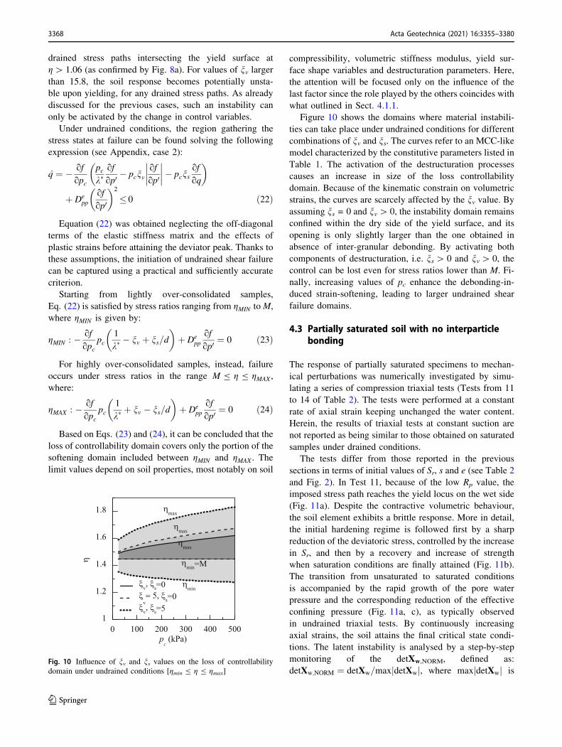
Based on Eqs. (23) and (24), it can be concluded that the
loss of controllability domain covers only the portion of the
softening domain included between gMIN and gMAX . The
limit values depend on soil properties, most notably on soil
compressibility, volumetric stiffness modulus, yield sur-
face shape variables and destructuration parameters. Here,
the attention will be focused only on the influence of the
last factor since the role played by the others coincides with
what outlined in Sect. 4.1.1.
Figure 10 shows the domains where material instabili-
ties can take place under undrained conditions for different
combinations of nv and ns. The curves refer to an MCC-like
model characterized by the constitutive parameters listed in
Table 1. The activation of the destructuration processes
causes an increase in size of the loss controllability
domain. Because of the kinematic constrain on volumetric
strains, the curves are scarcely affected by the nv value. Byassuming ns = 0 and nv[ 0, the instability domain remains
confined within the dry side of the yield surface, and its
opening is only slightly larger than the one obtained in
absence of inter-granular debonding. By activating both
components of destructuration, i.e. ns[ 0 and nv[ 0, the
control can be lost even for stress ratios lower than M. Fi-
nally, increasing values of pc enhance the debonding-in-
duced strain-softening, leading to larger undrained shear
failure domains.
4.3 Partially saturated soil with no interparticlebonding
The response of partially saturated specimens to mechan-
ical perturbations was numerically investigated by simu-
lating a series of compression triaxial tests (Tests from 11
to 14 of Table 2). The tests were performed at a constant
rate of axial strain keeping unchanged the water content.
Herein, the results of triaxial tests at constant suction are
not reported as being similar to those obtained on saturated
samples under drained conditions.
The tests differ from those reported in the previous
sections in terms of initial values of Sr, s and e (see Table 2
and Fig. 2). In Test 11, because of the low Rp value, the
imposed stress path reaches the yield locus on the wet side
(Fig. 11a). Despite the contractive volumetric behaviour,
the soil element exhibits a brittle response. More in detail,
the initial hardening regime is followed first by a sharp
reduction of the deviatoric stress, controlled by the increase
in Sr, and then by a recovery and increase of strength
when saturation conditions are finally attained (Fig. 11b).
The transition from unsaturated to saturated conditions
is accompanied by the rapid growth of the pore water
pressure and the corresponding reduction of the effective
confining pressure (Fig. 11a, c), as typically observed
in undrained triaxial tests. By continuously increasing
axial strains, the soil attains the final critical state condi-
tions. The latent instability is analysed by a step-by-step
monitoring of the detXw,NORM, defined as:
detXw;NORM ¼ detXw=max detXwj j, where max detXwj j is
0 100 200 300 400 500p
c (kPa)
1
1.2
1.4
1.6
1.8
η
ξv, ξ
s=0ξ
v= 5, ξ
s=0ξ
v, ξ
s=5
ηmax
ηmax
ηmax
ηmin=M
ηmin
Fig. 10 Influence of nv and ns values on the loss of controllability
domain under undrained conditions [gmin B g B gmax]
3368 Acta Geotechnica (2021) 16:3355–3380
123
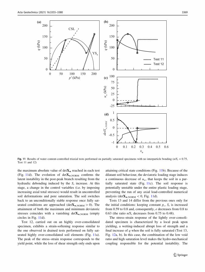
the maximum absolute value of detXw reached in each test
(Fig. 11d). The evolution of detXw,NORM confirms the
latent instability in the post-peak branch resulting from the
hydraulic debonding induced by the Sr increase. At this
stage, a change in the control variables (i.e. by imposing
increasing axial total stresses) would result in uncontrolled
soil deformations and pore saturation. The soil switches
back to an unconditionally stable response once fully sat-
urated conditions are approached (detXw,NORM[ 0). The
attainment of both the maximum and minimum deviatoric
stresses coincides with a vanishing detXw,NORM (empty
circles in Fig. 11d).
Test 12, carried out on an highly over-consolidated
specimen, exhibits a strain-softening response similar to
the one observed in drained tests performed on fully sat-
urated highly over-consolidated soil elements (Fig. 11a).
The peak of the stress–strain response corresponds to the
yield point, while the loss of shear strength only ends upon
attaining critical state conditions (Fig. 11b). Because of the
dilatant soil behaviour, the deviatoric loading stage induces
a continuous decrease of uw, that keeps the soil in a par-
tially saturated state (Fig. 11c). The soil response is
potentially unstable under the entire plastic loading stage,
preventing the run of any axial load-controlled numerical
analysis (detXw,NORM\ 0, Fig. 11d).
Tests 13 and 14 differ from the previous ones only for
the initial conditions: keeping constant pc, Sr is increased
from 0.59 to 0.8 and, consequently, e decreases from 0.8 to
0.63 (the ratio n/Sr decreases from 0.75 to 0.48).
The stress–strain response of the lightly over-consoli-
dated specimen is characterized by a local peak upon
yielding, a wetting-induced abrupt loss of strength and a
final increase of q when the soil is fully saturated (Test 13,
Fig. 12a, b). In this case, the combination of the low void
ratio and high saturation level makes the hydro-mechanical
coupling responsible for the potential instability. The
0 50 100 150 200p' (kPa)
0
50
100
150
200
q (k
Pa)
-25
0
25
50
75
100
u w(k
Pa)
Test 11Test 12
0
50
100
150
200
q (k
Pa)
(a) (b)
(c)
YS0
CSL
0 0.1 0.2 0.3 0.4 0.5 0.6εa
-1
-0.5
0
0.5
1
detX
w,N
ORM
(d)
Fig. 11 Results of water content-controlled triaxial tests performed on partially saturated specimens with no interparticle bonding (n/Sr = 0.75,
Test 11 and 12)
Acta Geotechnica (2021) 16:3355–3380 3369
123
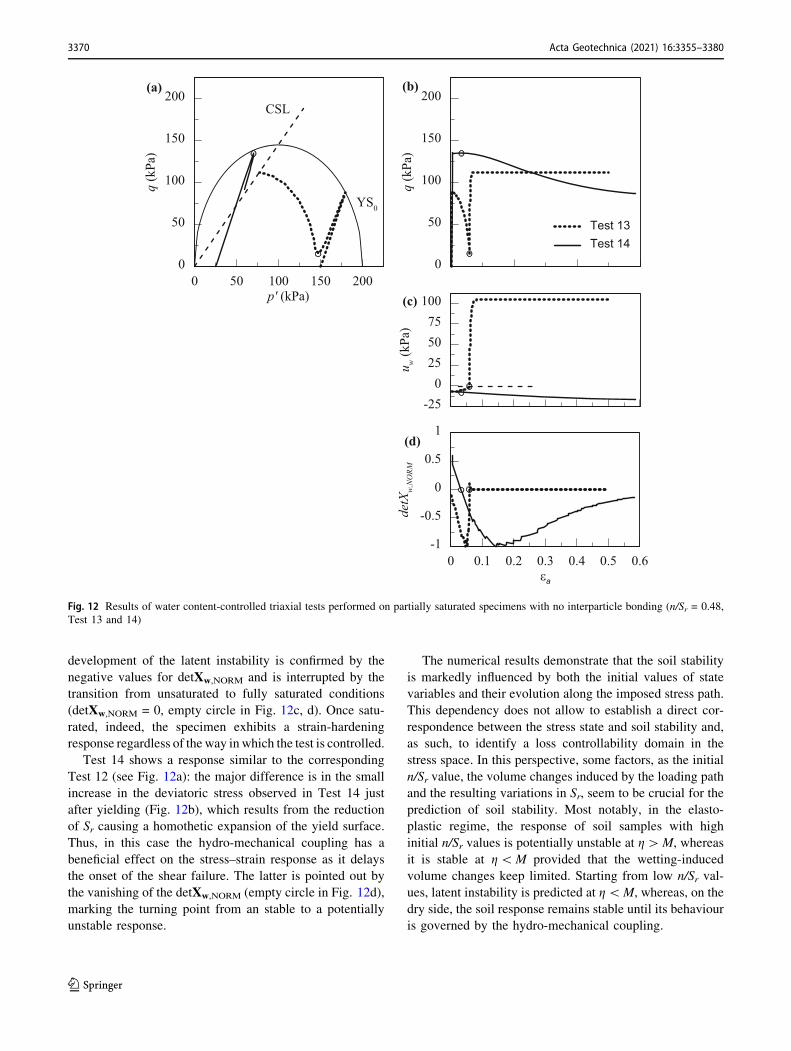
development of the latent instability is confirmed by the
negative values for detXw,NORM and is interrupted by the
transition from unsaturated to fully saturated conditions
(detXw,NORM = 0, empty circle in Fig. 12c, d). Once satu-
rated, indeed, the specimen exhibits a strain-hardening
response regardless of the way in which the test is controlled.
Test 14 shows a response similar to the corresponding
Test 12 (see Fig. 12a): the major difference is in the small
increase in the deviatoric stress observed in Test 14 just
after yielding (Fig. 12b), which results from the reduction
of Sr causing a homothetic expansion of the yield surface.
Thus, in this case the hydro-mechanical coupling has a
beneficial effect on the stress–strain response as it delays
the onset of the shear failure. The latter is pointed out by
the vanishing of the detXw,NORM (empty circle in Fig. 12d),
marking the turning point from an stable to a potentially
unstable response.
The numerical results demonstrate that the soil stability
is markedly influenced by both the initial values of state
variables and their evolution along the imposed stress path.
This dependency does not allow to establish a direct cor-
respondence between the stress state and soil stability and,
as such, to identify a loss controllability domain in the
stress space. In this perspective, some factors, as the initial
n/Sr value, the volume changes induced by the loading path
and the resulting variations in Sr, seem to be crucial for the
prediction of soil stability. Most notably, in the elasto-
plastic regime, the response of soil samples with high
initial n/Sr values is potentially unstable at g[M, whereas
it is stable at g\M provided that the wetting-induced
volume changes keep limited. Starting from low n/Sr val-
ues, latent instability is predicted at g\M, whereas, on the
dry side, the soil response remains stable until its behaviour
is governed by the hydro-mechanical coupling.
0 50 100 150 200p' (kPa)
0
50
100
150
200
q (k
Pa)
-250
255075
100
u w(k
Pa)
Test 13Test 14
0
50
100
150
200
q (k
Pa)
(a) (b)
(c)
YS0
CSL
0 0.1 0.2 0.3 0.4 0.5 0.6εa
-1
-0.5
0
0.5
1
detX
w,N
ORM
(d)
Fig. 12 Results of water content-controlled triaxial tests performed on partially saturated specimens with no interparticle bonding (n/Sr = 0.48,
Test 13 and 14)
3370 Acta Geotechnica (2021) 16:3355–3380
123
4.3.1 Stability criteria in analytical form
The numerical results highlight a remarkable increase in
complexity of the stability analyses when switching from
saturated to unsaturated conditions.
In tests at constant suction, the loss of controllability
domain is confined to the dry side of the yield surface,
where the soil exhibits a strain-softening response. Under
undrained conditions (i.e. keeping fixed the water content),
the failure domain is expected to vary during the defor-
mation process because of the dependency of the soil sta-
bility on the incremental loading path and the evolving
state of the material.
The instability of unsaturated soils under axisymmetric
loading paths occurs when:
_q ¼ Dqp _ev þ Dqq _es � Dqw_Sr � 0 ð25Þ
where Dqp, Dqw are the terms of the elasto-plastic hydro-
mechanical stiffness matrix linking _q to _ev, and _Sr,respectively. Equation (25) is satisfied when (see Appen-
dix, case 3):
_Sr �� 1
Depp� of
op0 =ofopc
k�
pc
_p
� nSrþ 1
Depp� of
op0 =ofopc
k�
pc
osoSr
Sr
þ s
þ bk�h i
ð26Þ
By expressing:
n
Sr
�
lim
¼ 1
Depp
� of
op0=of
opc
k�
pc
!
os
oSrSr
�
þ s
�
þ bk�
ð27Þ
Equation (26) can be simplified into the following form:
_Sr �� 1
Depp� of
op0 =ofopc
k�
pc
_p
� nSrþ n
Sr
lim
h i ð28Þ
In Eq. (27), osoSr
is the slope of the WRC, and osoSr
Sr
þ s
controls the variations of _p0induced by the changes in pore
saturation. This solution is obtained by neglecting the off-
diagonal terms of elastic stiffness matrix, following an
approach similar to the one adopted in the previous cases.
The numerator in Eq. (28) evolves with both the current
stress state and state variables, keeping, in all the investi-
gated cases, a value close to zero. It follows that, under the
compaction regime ( _ev[0, _Sr[0), the soil response remains
stable for n/Sr larger than the limit value. By contrast, the
dilatant behaviour ( _ev\0, _Sr\0) leads to latent instability
when n/Sr exceeds the limit value. Therefore, the potential
triggering of instability can be captured by comparing n/Sr,
here used as a compact descriptor of the state of the
material, with its limit value that delimits the state under
which the soil response is controlled by the hydro-me-
chanical coupling. It worth noting that the ratio n/Sr used
above is defined for degrees of saturation ranging over the
open interval (0,1), where the endpoints representing dry
and fully saturated conditions, respectively, are neglected.
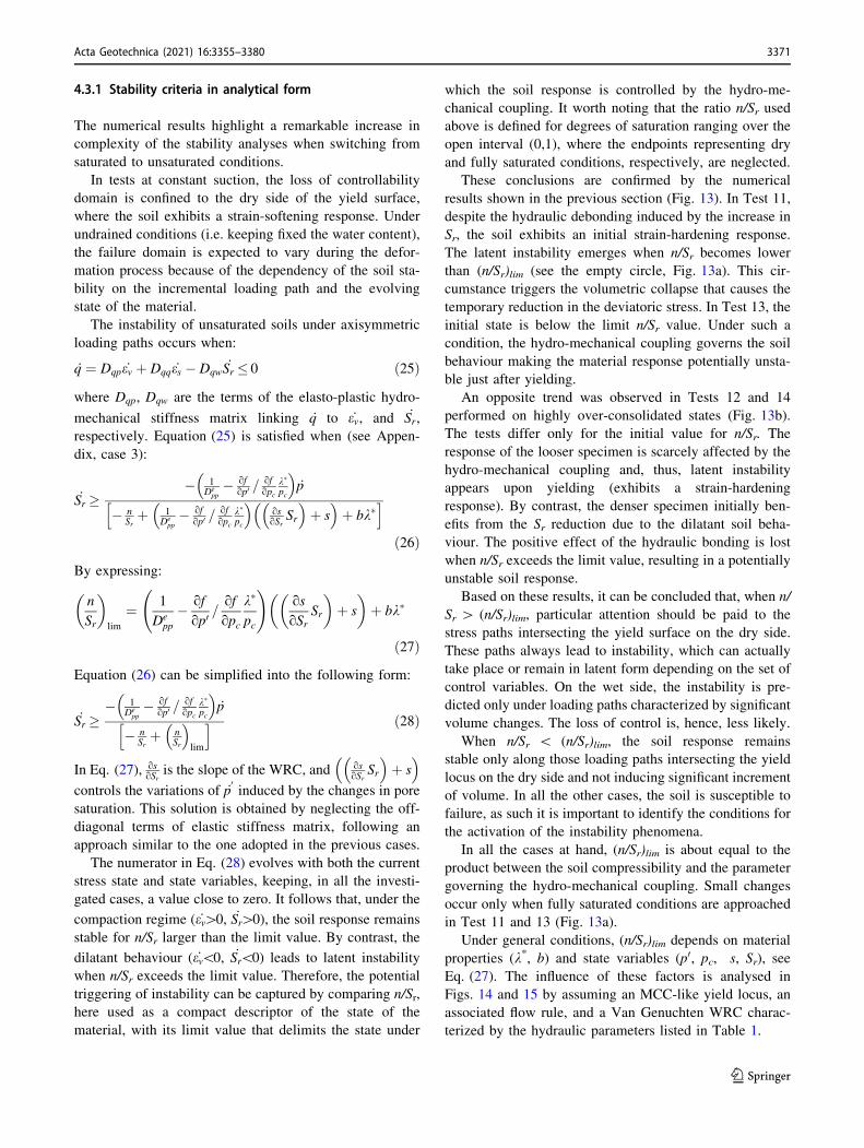
These conclusions are confirmed by the numerical
results shown in the previous section (Fig. 13). In Test 11,
despite the hydraulic debonding induced by the increase in
Sr, the soil exhibits an initial strain-hardening response.
The latent instability emerges when n/Sr becomes lower
than (n/Sr)lim (see the empty circle, Fig. 13a). This cir-
cumstance triggers the volumetric collapse that causes the
temporary reduction in the deviatoric stress. In Test 13, the
initial state is below the limit n/Sr value. Under such a
condition, the hydro-mechanical coupling governs the soil
behaviour making the material response potentially unsta-
ble just after yielding.
An opposite trend was observed in Tests 12 and 14
performed on highly over-consolidated states (Fig. 13b).
The tests differ only for the initial value for n/Sr. The
response of the looser specimen is scarcely affected by the
hydro-mechanical coupling and, thus, latent instability
appears upon yielding (exhibits a strain-hardening
response). By contrast, the denser specimen initially ben-
efits from the Sr reduction due to the dilatant soil beha-
viour. The positive effect of the hydraulic bonding is lost
when n/Sr exceeds the limit value, resulting in a potentially
unstable soil response.
Based on these results, it can be concluded that, when n/
Sr [ (n/Sr)lim, particular attention should be paid to the
stress paths intersecting the yield surface on the dry side.
These paths always lead to instability, which can actually
take place or remain in latent form depending on the set of
control variables. On the wet side, the instability is pre-
dicted only under loading paths characterized by significant
volume changes. The loss of control is, hence, less likely.
When n/Sr \ (n/Sr)lim, the soil response remains
stable only along those loading paths intersecting the yield
locus on the dry side and not inducing significant increment
of volume. In all the other cases, the soil is susceptible to
failure, as such it is important to identify the conditions for
the activation of the instability phenomena.
In all the cases at hand, (n/Sr)lim is about equal to the
product between the soil compressibility and the parameter
governing the hydro-mechanical coupling. Small changes
occur only when fully saturated conditions are approached
in Test 11 and 13 (Fig. 13a).
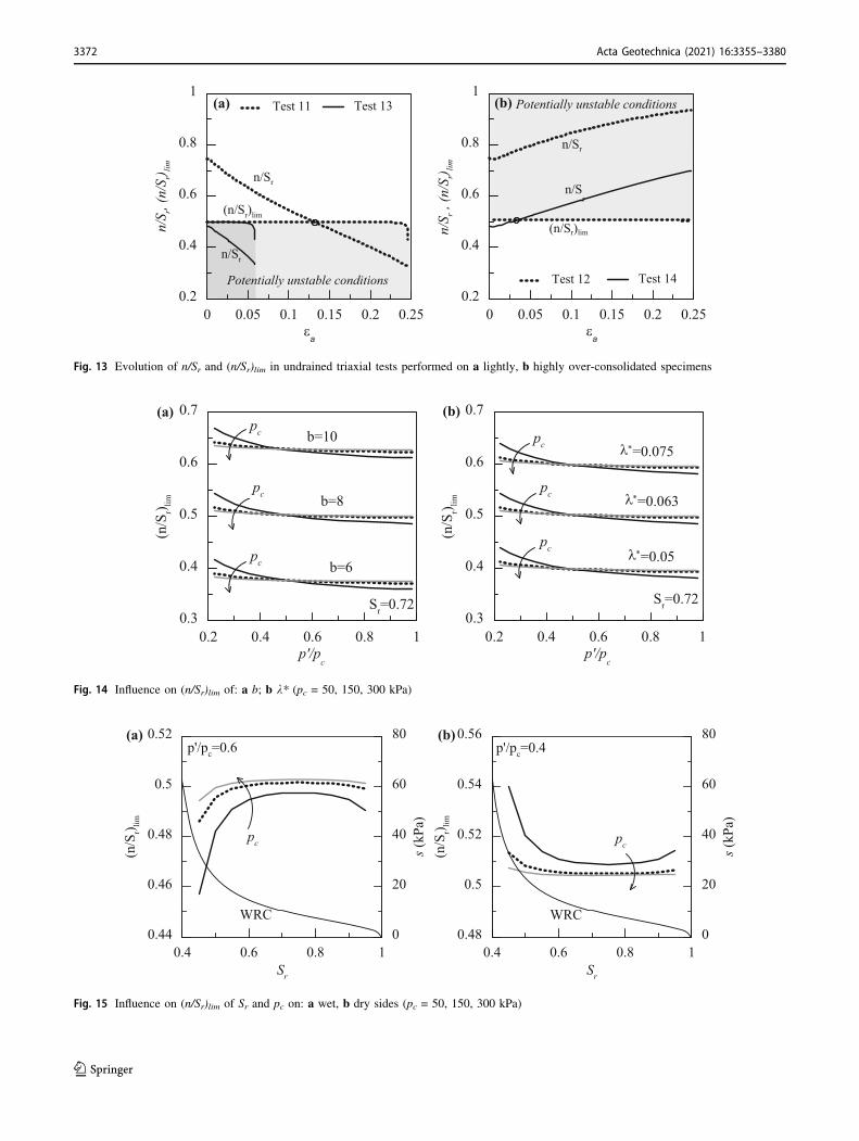
Under general conditions, (n/Sr)lim depends on material
properties (k*, b) and state variables (p0, pc, s, Sr), see
Eq. (27). The influence of these factors is analysed in
Figs. 14 and 15 by assuming an MCC-like yield locus, an
associated flow rule, and a Van Genuchten WRC charac-
terized by the hydraulic parameters listed in Table 1.
Acta Geotechnica (2021) 16:3355–3380 3371
123
0 0.05 0.1 0.15 0.2 0.25εa
0.2
0.4
0.6
0.8
1
n/S r ,
(n/S
r) lim
Test 14Test 12
0 0.05 0.1 0.15 0.2 0.25εa
0.2
0.4
0.6
0.8
1
n/S r,
(n/S
r) lim
Test 13Test 11(a) (b)
Potentially unstable conditions
Potentially unstable conditions
n/Sr
(n/Sr)lim
n/Sr
n/Sr
(n/Sr)lim
n/Sr
Fig. 13 Evolution of n/Sr and (n/Sr)lim in undrained triaxial tests performed on a lightly, b highly over-consolidated specimens
0.2 0.4 0.6 0.8 1p'/p
c
0.3
0.4
0.5
0.6
0.7
(n/S
r) lim
b=10
b=8
b=6
pc
pc
pc
0.2 0.4 0.6 0.8 1p'/p
c
0.3
0.4
0.5
0.6
0.7
(n/S
r) limλ*=0.075
λ*=0.063
λ*=0.05
pc
pc
pc
(a) (b)
Sr=0.72 Sr=0.72
Fig. 14 Influence on (n/Sr)lim of: a b; b k* (pc = 50, 150, 300 kPa)
0.4 0.6 0.8 1Sr
0.44
0.46
0.48
0.5
0.52
(n/S
r) lim
0
20
40
60
80
s (kP
a)
p'/pc=0.6
0.4 0.6 0.8 1Sr
0.48
0.5
0.52
0.54
0.56
(n/S
r) lim
0
20
40
60
80s (
kPa)
pc
p'/pc=0.4
WRC
pc
WRC
(a) (b)
Fig. 15 Influence on (n/Sr)lim of Sr and pc on: a wet, b dry sides (pc = 50, 150, 300 kPa)
3372 Acta Geotechnica (2021) 16:3355–3380
123
Increasing values of b or k* enhance the hydro-me-
chanical coupling, leading to higher values of (n/Sr)lim (see
Fig. 14a, b). For a fixed value of b or k*, (n/Sr)lim depends
on both pc and the ratio p0/pc that defines the position of the
current stress state on the yield surface. Increasing values
of pc imply a decrease of the limit value on the dry side (p0/pc\ 0.5), and a slight increase on the wet side (p0/pc-[ 0.5). For fixed pc, (n/Sr)lim decreases for increasing p0/pc, assuming a constant value on the wet side.
Finally, Fig. 15 shows the influence of pore saturation
on (n/Sr)lim. Figure 15a refers to stress states lying on the
wet side at p0/pc = 0.6. Regardless of the pc value, no
significant changes in (n/Sr)lim are observed under pore
saturation ranging from 0.65 to 0.85. In this range, the
moderate slope of the WRC augments the hydro-mechan-
ical coupling, keeping (n/Sr)lim to the maximum value. By
contrast, when Sr approaches the residual value or full
saturation, the slope of WRC appreciably increases causing
significant reductions in the (n/Sr)lim value. On the dry side,
the curve follows the opposite trend (see Fig. 15b related to
p0/pc of 0.4). Indeed, (n/Sr)lim keeps at its minimum value
when Sr ranges from 0.65 to 0.85, whereas appreciably
increases when Sr is outside this range.
In conclusion, on the wet side, the instability is more
likely in highly collapsing soils, characterized by large
values of b and k* and small slopes of the WRC. By
contrast, on the dry side, the risks associated with a
potential loss of control are higher in hard soils having low
b values and WRCs with small slopes.
4.4 Partially saturated soil with destructuration
The combined effect of partial saturation and bond degra-
dation on the hydro-mechanical behaviour is here investi-
gated by simulating two compression triaxial tests under
constant water content (Tests 15, 16 of Table 2). These
simulations differ from Tests 11 and 12 only for the acti-
vation of the destructuration processes. Herein, the results
of triaxial tests at constant suction are not reported since
they are similar to those obtained on bonded fully saturated
samples under drained conditions.
In Test 15, the deviator peak coincides with the yield
point (see Fig. 16a). The brittleness in the soil response
results from the combined effect of the strain-induced
structure degradation and the homothetic contraction of the
yield locus due to the increase in Sr. After this initial
softening, the deviatoric stress lightly increases again, as
the impact of the debonding process reduces for increasing
cumulated plastic strains. This trend is inverted once the
hydro-mechanical coupling becomes the main factor con-
trolling the soil behaviour (see Fig. 16b): at this stage, the
increase in Sr leads to a significant reduction in q down to
extension triaxial stress conditions. Once the material is
fully saturated, the stress path reverses again its direction
and q starts increasing, initially along an almost p0 path, tothen deviate to the left towards the critical state line. This
trend is due to the sudden build-up of positive excess pore
water pressures related to the imposed kinematic constraint
(see Fig. 16c). Before reaching the final stationary condi-
tions, a further light decrease of the deviatoric stress is
observed: this feature should be ascribed to the residual de-
structuring process still ongoing at that final stage.
Once again, the mixed stress–strain control guarantees
the stability of the soil response. However, under unsatu-
rated conditions, latent instabilities are observed just after
yielding and before full saturation. The vanishing of detXw
coincides with the attainment of the local minimum and
maximum of the deviatoric stress. When fully saturated,
the soil response is again potentially unstable once the
critical state line is approached, as confirmed by the neg-
ative values for detXw.
In Test 16, the material exhibits a brittle response sim-
ilarly to what observed in the absence of cementation
bonds (see Test 12). The activation of the structure
degradation makes the loss of shear strength more rapid as
compared to that observed for the unstructured case. The
dilatant soil behaviour keeps the material in an unsaturated
regime and leads to increasing suctions (see Fig. 16c). The
hydraulic hardening induced by the reduction of Sr is not
sufficient to balance the mechanical softening. The soil
response is, hence, potentially unstable along the entire
stress path (detXw\ 0, Fig. 16d).
These results indicate that the activation of the
destructuration process causes an increase in size of the
loss of controllability domain as compared to the case with
no cementation bonds. Upon yielding, the domain gather-
ing the potentially unstable stress states covers the entire
yield surface. However, this outcome should not be gen-
eralized, as it depends on the specific test conditions and
soil properties assumed in the proposed tests. Moreover,
the domain evolves with the material state, as already
found for unstructured unsaturated soils.
4.4.1 Stability criteria in analytical form
The results shown in the previous section confirm the
ability of the controllability theory to capture potential/
actual instabilities in undrained triaxial tests performed on
structured unsaturated soils. Under undrained conditions,
just after yielding (epv , eps ¼ 0), the instability phenomena
take place when (see Appendix, case 4):
Acta Geotechnica (2021) 16:3355–3380 3373
123
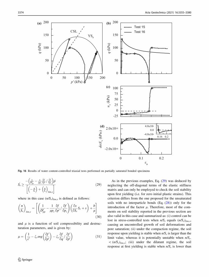
_Sr �� 1
Depp� 1
lpcofop0 =
ofopc
_p
� nSr
þ nSr
lim;s
� � ð29Þ
where in this case (n/Sr)lim,s is defined as follows:
n
Sr
�
lim;s
¼ 1
Depp
� 1
lpc
of
op0=of
opc
!
os
oSrSr þ s
�
þ b
l
" #
ð30Þ
and l is a function of soil compressibility and destruc-
turation parameters, and is given by:
l ¼ 1
k�� nvsng
of
op0
�
� nsof
oq=of
op0
�
ð31Þ
As in the previous examples, Eq. (29) was deduced by
neglecting the off-diagonal terms of the elastic stiffness
matrix and can only be employed to check the soil stability
upon first yielding (i.e. for zero initial plastic strains). This
criterion differs from the one proposed for the unsaturated
soils with no interparticle bonds (Eq. (28)) only for the
introduction of the factor l. Therefore, most of the com-
ments on soil stability reported in the previous section are
also valid in this case and summarized as: (i) control can be
lost in stress-controlled tests when n/Sr equals (n/Sr)lim,s,
causing an uncontrolled growth of soil deformations and
pore saturation; (ii) under the compaction regime, the soil
response upon yielding is stable when n/Sr is larger than the
limit value, whereas it is potentially unstable when n/Sr-\ (n/Sr)lim,s; (iii) under the dilatant regime, the soil
response at first yielding is stable when n/Sr is lower than
0 50 100 150 200p' (kPa)
0
50
100
150
200
q (k
Pa)
-250
255075
100
u w(k
Pa)
Test 15Test 16
0
50
100
150
200
q (k
Pa)
(a) (b)
(c)
YS0
CSL
0 0.1 0.2εa
-2.0x10¹⁰
0.0
2.0x10¹⁰
detX
w(k
Pa3)
(d)
0.16 0.2-4.0x10⁶
0.04.0x106
Fig. 16 Results of water content-controlled triaxial tests performed on partially saturated bonded specimens
3374 Acta Geotechnica (2021) 16:3355–3380
123
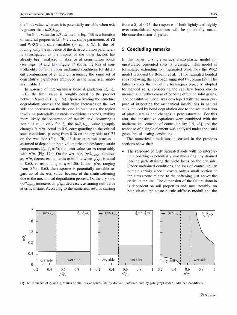
the limit value, whereas it is potentially unstable when n/Sris greater than (n/Sr)lim,s.
The limit value for n/Sr defined in Eq. (30) is a function
of material properties (k*, b, nv, ns, shape parameters of YS
and WRC) and state variables (p0, pc, s, Sr). In the fol-
lowing, only the influence of the destructuration parameters
is investigated, as the impact of the other factors has
already been analysed in absence of cementation bonds
(see Figs. 14 and 15). Figure 17 shows the loss of con-
trollability domains under undrained conditions for differ-
ent combination of nv and ns, assuming the same set of
constitutive parameters employed in the numerical analy-
ses (Table 1).
In absence of inter-granular bond degradation (nv, ns-= 0), the limit value is roughly equal to the product
between b and k* (Fig. 17a). Upon activating the structure
degradation process, the limit value increases on the wet
side and decreases on the dry one. In both cases, the region
involving potentially unstable conditions expands, making
more likely the occurrence of instabilities. Assuming a
non-null value only for nv, the (n/Sr)lim,s value abruptly
changes at p0/pc equal to 0.5, corresponding to the critical
state conditions, passing from 0.38 on the dry side to 0.73
on the wet side (Fig. 17b). If destructuration process is
assumed to depend on both volumetric and deviatoric strain
components (nv, ns = 5), the limit value varies remarkably
with p0/pc (Fig. 17c). On the wet side, (n/Sr)lim,s increases
as p0/pc decreases and tends to infinite when p0/pc is equalto 0.65, corresponding to g = 1.06. Under p0/pc ranging
from 0.5 to 0.65, the response is potentially unstable re-
gardless of the n/Sr value, because of the strain-softening
due to the mechanical degradation process. On the dry side,
(n/Sr)lim,s increases as p0/pc decreases, assuming null value
at critical state. According to the numerical results, starting
from n/Sr of 0.75, the response of both lightly and highly
over-consolidated specimens will be potentially unsta-
ble once the material yields.
5 Concluding remarks
In this paper, a single-surface elasto-plastic model for
unsaturated cemented soils is presented. This model is
formulated extending to unsaturated conditions the WR2
model proposed by Boldini et al. [7] for saturated bonded
soils following the approach suggested by Jommi [29]. The
latter exploits the modelling techniques typically adopted
for bonded soils, considering the capillary forces due to
menisci as a further cause of bonding effect on solid grains.
The constitutive model was developed with the main pur-
pose of inspecting the mechanical instabilities in natural
soils induced by bond degradation due to the accumulation
of plastic strains and changes in pore saturation. For this
aim, the constitutive equations were combined with the
mathematical concept of controllability [15, 43], and the
response of a single element was analysed under the usual
geotechnical testing conditions.
The numerical simulations discussed in the previous
sections show that:
• The response of fully saturated soils with no interpar-
ticle bonding is potentially unstable along any drained
loading path attaining the yield locus on the dry side.
Under undrained conditions, the loss of controllability
domain shrinks since it covers only a small portion of
the stress zone related to the softening just above the
critical state line. The dimension of the failure domain
is dependent on soil properties and, most notably, on
both elastic and elasto-plastic stiffness moduli and the
0.2 0.4 0.6 0.8 1p'/pc
0
0.4
0.8
1.2
1.6
2
n/S r
(n/Sr)lim,s ξv, ξs=0
0.2 0.4 0.6 0.8 1p'/pc
(n/Sr)lim,s ξv=5, ξs=0
0.2 0.4 0.6 0.8 1p'/pc
(n/Sr)lim,s ξv,
ξs=5
dry side wet side dry side wet side dry side wet side
Fig. 17 Influence of nv and ns values on the loss of controllability domain (coloured area by pale grey) under undrained conditions
Acta Geotechnica (2021) 16:3355–3380 3375
123
shape of the yield locus, as highlighted by the proposed
stability criterion;
• Regardless of drainage conditions, the loss of control-
lability domain for fully saturated structured soils is
larger than the one observed in the unbonded case.
Depending on the rate of the degradation process, the
failure domain might result as no longer confined to the
dry side of the yield locus. Its initial opening under
drained and undrained conditions can be determined
using the analytical criteria presented in this paper, once
the soil properties and material state are known;
• Under constant suction conditions, the loss of control-
lability domain of partially saturated soils with no
interparticle bonding is confined within the dry side of
the yield locus. Under constant water content condi-
tions, the failure domain cannot be univocally defined
since the soil response is strongly dependent on the
initial values of the state variables and their evolution
along the imposed loading path. Nevertheless, the
proposed stability criterion can be fruitfully employed
to identify the scenarios where the onset of instability
phenomena is more likely. Such criterion highlights the
crucial role played by the hydro-mechanical soil
properties (k*, b) and the evolving state of the material
(e, p0, pc, s, Sr) on the occurrence of uncontrolled
deformation processes;
• Similarly to what observed for fully saturated soils, the
progressive breakage of the interparticle bonding in
structured unsaturated soils leads to a larger loss of
controllability domain compared to the case of
unbonded unsaturated soils. As confirmed by the
proposed analytical criterion, the structure degradation
process makes more likely the occurrence of instability
phenomena under generic loading paths.
In conclusion, the results of this study confirm the
ability of the proposed constitutive model to capture the
basic hydro-mechanical phenomena affecting the beha-
viour of cemented unsaturated soils. In particular, the
model provides a good description of phenomena, i.e. the
strain-induced structure degradation and wetting-induced
collapse, that, under certain loading conditions, could give
rise to instability mechanisms. It is worth recalling that the
numerical results reported in this paper refer to single
elements subjected to mechanical perturbations. In per-
spective, the ability of the model in reproducing the
response of natural soils is left to be explored under drying
and wetting paths and in boundary value problems, where
the combined effect of structure and partial saturation
might play a role in the response of a whole deposit of soil.
Appendix
Case 1
This sub-section illustrates the analytical derivation of the
stability criterion proposed to capture the onset of
undrained shear failure in fully saturated soil samples. The
maximum deviator stress that the soil can sustain under
axisymmetric loading paths is given by Eq. (16). Thanks to
the kinematic constrain deriving from the assumption of
undrained conditions, the above equation can be simplified
as follows:
_q ¼ Dqq _es ¼ 0 ð32Þ
Equation (32) is satisfied for any deviatoric strain
increment when Dqq = 0.
The elasto-plastic constitutive matrix governing the
mechanical behaviour is defined in Eq. (10). Assuming an
associated flow rule and neglecting the off-diagonal terms
of the elastic stiffness matrix, the term Dqq results:
Dqq ¼ Deqq �
1
H þ HcDe
qq2 of
oq
� 2
ð33Þ
where Deqq is the term of elastic stiffness matrix linking _q to
the strain increment _es and of=oq is the partial derivative of
the yield surface with respect to q.
The stability criterion Dqq = 0 can be rewritten as fol-
lows (since Deqq=0, H ? Hc = 0):
H þ Hc � Deqq
of
oq
� 2
¼ 0 ð34Þ
By substituting Eqs. (11) and (12) in Eq. (34), the cri-
terion can be reformulated in the form:
of
op0� of
opc
pck�
þ Depp
of
op0
� �
¼ 0 ð35Þ
Equation (35) is satisfied when the current stress ratio
equals gMAX (see Eq. (17)) and under critical state condi-
tions, i.e. when of=op0 ¼ 0:
Case 2
In this sub-section, the mathematical demonstration of the
stability criterion for fully saturated structured soils under
undrained conditions is presented.
For structured soils, the hardening modulus is defined as
follows:
H ¼ � of
opc
pck�
of
op0� pcnv e�gve
dv
of
op0
�
�
�
�
�
�
�
�
� pcns e�gseps
of
oq
�
ð36Þ
3376 Acta Geotechnica (2021) 16:3355–3380
123
By neglecting the small plastic strains developed before
attaining the deviator peak, Eq. (36) can be simplified as
follows:
H ¼ � of
opc
pck�
of
op0� pcnv
of
op0
�
�
�
�
�
�
�
�
� pcnsof
oq
�
ð37Þ
By introducing Eqs. (12) and (37) in Eq. (34), the sta-
bility criterion is given by:
� of
opc
pck�
of
op0� pcnv
of
op0
�
�
�
�
�
�
�
�
� pcnsof
oq
�
þ Depp
of
op0
� 2
¼ 0
ð38Þ
or analogously:
of
op0� of
opcpc
1
k�� nvsgn
of
op0
�
þ ns=d
�
þ Depp
of
op0
� �
¼ 0
ð39Þ
In plastic loadings, Eq. (39) is verified: at low Rp values,
when the stress ratio is equal to gMIN defined in Eq. (23)
and at critical state; at high values of Rp, when the stress
ratio equals gMAX , defined in Eq. (24), and M.
Case 3
The stress–strain response of unsaturated soils is controlled
by the following constitutive equation:
_q ¼ Dqp _ev þ Dqq _es � Dqw_Sr ð40Þ
By assuming a diagonal elastic stiffness matrix and an
associated flow rule, Eq. (40) can be rewritten in the fol-
lowing form (see Eqs. (10) and (13)):
_q ¼ � 1
H þ HcDe
ppDeqq
of
op0of
oq
�
_ev
þ Deqq �
1
H þ HcDe
of
oq
� 2 !
_es
þ 1
H þ Hc
of
opcbpcD
eqq
of
oq_Sr ð41Þ
Equation (41) can be rearranged as follows:
_qH þ Hc
Deqq
¼ �Depp
of
op0of
oq
�
_ev
þ H þ Hc � Deqq
of
oq
� 2 !
_es þof
opcbpc
of
oq_Sr
ð42Þ
By decomposing the deviatoric strain increment in the
elastic and plastic contributions, Eq. (42) simplifies into:
_qof
oq
� 2
¼ �Depp
of
op0of
oq
�
_ev
þ H þ Hc � Deqq
of
oq
� 2 !
_eps þof
opcbpc
of
oq_Sr
ð43Þ
By introducing Eq. (12) in Eq. (43), the latter modifies
as follows:
_qof
oq
� 2
¼ �Depp
of
op0of
oq
�
_ev
þ Hof
oq=of
op0þ De
pp
of
oq
of
op0
�
_epv þof
opcbpc
of
oq_Sr
ð44Þ
Bearing in mind that _epv can be expressed as difference
between the total and elastic components, Eq. (44) can be
rewritten as follows:
_qof
oq¼ H=
of
op0_ev
�
þ � H
Depp
=of
op0� of
op0
!
_p0 þ of
opcbpc _Sr
ð45Þ
where _p0 is defined as _p0 ¼ _pþ Sr _sþ _Srs, and _ev is linked to_Sr by the following relationship, resulting from the con-
strain on the water content:
_evSr � n _Sr ¼ 0 ð46Þ
The instability occurs when:
of
oq
� �1
H=of
op0_ev
�
þ � H
Depp
=of
op0� of
op0
!
_p0 þ of
opcbpc _Sr
" #
� 0
ð47Þ
Since the term of=oq is always positive, the instability
takes place when:
H=of
op0_ev
�
þ � H
Depp
=of
op0� of
op0
!
_p0 þ of
opcbpc _Sr
" #
� 0
ð48Þ
Equation (48) can be simplified by introducing the
definition of H (see Eq. (11), and expressing _ev as a func-
tion of _Sr (see Eq. (46)):
� of
opc
opcoevp
_nSrSr
�
þ 1
Depp
of
opc
opcoevp
� of
op0
!
_p0 þ of
opcbpc _Sr
" #
� 0
ð49Þ
Acta Geotechnica (2021) 16:3355–3380 3377
123
Finally, accounting for the definition of _p0, Eq. (49) canbe rearranged as follows:
� n
Sr
�
þ 1
Depp
� k�
pc
of
op0=of
opc
!
os
oSrSr þ s
�
þ bk�" #
_Sr �
� 1
Depp
� k�
pc
of
op0=of
opc
!
_p
ð50Þ
Case 4
The stability criterion for structured unsaturated soils can
be derived from Eq. (48) by substituting the expression of
the hardening modulus defined in Eq. (37). The latter
neglects the changes in intensity of the degradation process
with the accumulation of plastic strains (epv , eps ¼ 0).
At first yielding, the latent instability takes place when:
� 1
k�� nvsgn
of
op0
�
� nsof
oq=of
op0
�
of
opc_ev
� �
þ 1
Depp
1
k�� nvsgn
of
op0
�
� nsof
oq=of
op0
�
of
opc� 1
pc
of
op0
!
_p0
þ of
opcb _Sr
�
� 0
ð51Þ
By introducing the function l defined in Eq. (31),
Eq. (51) can be simplified as follows:
�lof
opc_ev
�
þ lDe
pp
of
opc� 1
pc
of
op0
!
_p0 þ of
opcb _Sr
" #
� 0
ð52Þ
By expressing _ev as a function of _Sr (see Eq. (46)) and
accounting for the definition of _p0, Eq. (52) can be rear-
ranged in:
�lof
opc
n
Sr
�
þ lDe
pp
of
opc� 1
pc
of
op0
!
os
oSrSr þ s
�
þ of
opcb
" #
_Sr � � lDe
pp
of
opc� 1
pc
of
op0
!
_p
ð53Þ
Finally, Eq. (53) can be further simplified:
� n
Sr
�
þ 1
Depp
� 1
lpc
of
op0=of
opc
!
os
oSrSr þ s
�
þ b
l
" #
_Sr �
� 1
Depp
� 1
lpc
of
op0=of
opc
!
_pv
ð54Þ
Funding Open access funding provided by Universita degli Studi di
Roma La Sapienza within the CRUI-CARE Agreement.
Open Access This article is licensed under a Creative Commons
Attribution 4.0 International License, which permits use, sharing,
adaptation, distribution and reproduction in any medium or format, as
long as you give appropriate credit to the original author(s) and the
source, provide a link to the Creative Commons licence, and indicate
if changes were made. The images or other third party material in this
article are included in the article’s Creative Commons licence, unless
indicated otherwise in a credit line to the material. If material is not
included in the article’s Creative Commons licence and your intended
use is not permitted by statutory regulation or exceeds the permitted
use, you will need to obtain permission directly from the copyright
holder. To view a copy of this licence, visit http://creativecommons.
org/licenses/by/4.0/.
References
1. Alonso E, Gens A, Josa A (1990) Constitutive model for partially
saturated soils. Geotechnique 40(3):405–430
2. Amorosi A, Rampello S (1998) The influence of natural soil
structure on the mechanical behaviour of a stiff clay. In: Pro-
ceedings of 2nd international symposium on geotechnics of hard
soils-soft rocks, Naples, Balkema, Rotterdam, vol 1, pp 395–402
3. Amorosi A, Rampello S (2007) An experimental investigation
into the mechanical behaviour of a structured stiff clay.
Geotechnique 57(2):153–166
4. Antinoro C, Arnone E, Noto LV (2017) The use of soil water
retention curve models in analysing slope stability in differently
structured soils. CATENA 150:133–145
5. Baudet B, Stallebrass S (2004) A constitutive model for struc-
tured clays. Geotechnique 54(4):269–278
6. Bigoni D, Piccolroaz A (2004) Yield criteria for quasibrittle and
frictional materials. Int J Solids Struct 41:2855–2878
7. Boldini D, Palmieri F, Amorosi A (2019) A new versatile con-
stitutive law for modelling the monotonic response of soft rocks
and structured fine-grained soils. Int J Numer Anal Methods
Geomech 43(15):2383–2406
8. Bolzon G, Schrefler A, Zienkiewicz OC (1996) Elasto-plastic
constitutive laws generalised to partially saturated states.
Geotechnique 46(2):279–289
9. Bruno AW, Gallipoli D, Rouainia M, Lloret-Cabot M (2020) A
bounding surface mechanical model for unsaturated cemented
soils under isotropic stresses. Comput Geotech 125:103673
10. Burland JB (1990) On the compressibility and shear strength of
natural clays. Geotechnique 40(3):329–378
11. Buscarnera G (2014) Uniqueness and existence in plasticity
models for unsaturated soils. Acta Geotech 9(2):313–327
12. Buscarnera G, Dattola G (2016) Mathematical capture of failure
processes in elastoplastic geomaterials. Soils Found 56(1):1–18
13. Buscarnera G, Nova R (2009) An elastoplastic strain-hardening
model for soil allowing for hydraulic bonding-debonding effects.
Int J Numer Anal Methods Geomech 33(8):1055–1086
14. Buscarnera G, Nova R (2011) Modelling instabilities in triaxial
testing on unsaturated soil specimens. Int J Numer Anal Methods
Geomech 35(2):179–200
15. Buscarnera G, di Prisco C (2012) Discussing the definition of the
second-order work for unsaturated soils. Int J Numer Anal
Methods Geomech 36(1):36–49
16. Casini F (2012) Deformation induced by wetting: a simple model.
Can Geotech J 49(8):954–960
3378 Acta Geotechnica (2021) 16:3355–3380
123
17. Casini F, Vassallo R, Mancuso C, Desideri A (2008) Application
to a compacted soil of a Cam Clay model extended to unsaturated
conditions. In: Unsaturated soils: advances in geo-engineering—
proc. 1st European conference on unsaturated soils, E-UNSAT
2008, pp 609–615
18. Castelblanco JM, Delage P, Pereira J, Cui Y (2011) Some aspects
of the compression and collapse behaviour of an unsaturated
natural loess. Geotechnique Letters 1(2):17–22
19. Chiu CF, Ng CWW (2003) A state-dependent elasto-plastic
model for saturated and unsaturated soils. Geotechnique
53(9):809–829
20. Cui YJ, Delage P (1996) Yielding and plastic behaviour of an
unsaturated compacted silt. Geotechnique 46(2):291–311
21. Cui YJ, Delage P, Sultan N (1995) An elasto-plastic model for
compacted soils. In: Unsaturated soils, Balkema, Rotterdam, vol
2, pp 703–709
22. Delage P, Cui YJ, Antoine P (2005) Geotechnical problems
related with loess deposits in Northern France. Physics
9(6):517–540
23. Gallipoli D, Bruno AW (2017) A bounding surface compression
model with a unified virgin line for saturated and unsaturated
soils. Geotechnique 67(8):703–712
24. Garitte B, Vaunat J, Gens A (2006) A constitutive model that
incorporates the effect of suction in cemented geological mate-
rials. In: Proceedings of 4th international conference on unsatu-
rated soils, Carefree, AZ, vol 2, pp 1944–1955
25. Gens A, Sanchez M, Sheng D (2006) On constitutive modelling
of unsaturated soils. Acta Geotech 1(3):137–147
26. Houlsby GT, Amorosi A, Rojas E (2005) Elastic moduli of soils
dependent on pressure: a hyperelastic formulation. Geotechnique
55(5):383–392
27. Houlsby GT, Amorosi A, Rollo F (2019) Non-linear anisotropic
hyperelasticity for granular materials. Comput Geotech
115:103167
28. Imposimato S, Nova R (1998) An investigation on the uniqueness
of the incremental response of elastoplastic models for virgin
sand. Mech Cohes Frict Mater 3(1):65–87
29. Jommi C (2000) Remarks on the constitutive modelling of
unsaturated soils. In: Tarantino A, Mancuso C (eds) Experimental
evidence and theoretical approaches in unsaturated soils. Balk-
ema, Rotterdam, pp 139–153
30. Josa A, Balmaceda A, Gens A, Alonso EE (1992) An elasto-
plastic model for partially saturated soil exhibiting a maximum of
collapse. In: 3rd international conference on computational
plasticity, Barcelona, vol 1, pp 815–826
31. Kavvadas MJ, Amorosi A (2000) A constitutive model for
structured soils. Geotechnique 50(3):263–273
32. Khalili N, Habte MA, Zargarbashi S (2008) A fully coupled flow
deformation model for cyclic analysis of unsaturated soils
including hydraulic and mechanical hysteresis. Comput Geotech
35(6):872–889
33. Kohler R, Hofstetter G (2008) A cap model for partially saturated
soils. Int J Numer Anal Methods Geomech 32(8):981–1004
34. Lagioia R, Nova R (1995) An experimental and theoretical study
of the behaviour of a calcarenite in triaxial compression.
Geotechnique 45(4):633–648
35. Lalicata LM, Rotisciani GM, Desideri A, Casini F, Thorel L
(2020) Numerical study of laterally loaded pile in unsaturated
soils. Lecture Notes Civ Eng 40:713–722
36. Leroueil S, Barbosa PDA (2000) Combined effect of fabric
bonding and partial saturation on yielding of soils. In: Unsatu-
rated soils for Asia, Balkema, Rotterdam, pp 527–532
37. Leroueil S, Vaughan PR (1990) The general and congruent
effects of structure in natural soils and weak rocks. Geotechnique
40(3):467–488
38. Liu D, Carter P (2002) A structured Cam Clay model. Can
Geotech J 39(6):1313–1332
39. Lourenco SDN, Gallipoli D, Augarde CE, Toll DG, Fisher PC,
Congreve A (2012) Formation and evolution of water menisci in
unsaturated granular media. Geotechnique 62(3):193–199
40. Marinelli F, Buscarnera G (2015) Parameter calibration for high-
porosity sandstones deformed in the compaction banding regime.
Int J Rock Mech Min Sci 78:240–252
41. Mihalache C, Buscarnera G (2014) Mathematical identification of
diffuse and localized instabilities in fluid-saturated sands. Int J
Numer Anal Methods Geomech 38(2):111–141
42. Navarro V, Alonso J, Calvo B, Sanchez J (2010) A constitutive
model for porous rock including effects of bond strength degra-
dation and partial saturation. Int J Rock Mech Min Sci
47(8):1330–1338
43. Nova R (1994) Controllability of the incremental response of soil
specimens subjected to arbitrary loading programmes. J Mech
Behav Mater 5:193–201
44. Nova R (2004) The role of non-normality in soil mechanics and
some of its mathematical consequences. Comput Geotech
31(3):185–191
45. Nuth M, Laloui L (2008) Effective stress concept in unsaturated
soils: clarification and validation of a unified framework. Int J
Numer Anal Methods Geomech 32(7):771–801
46. Pereira JM, Rouainia M, Manzanal D (2014) Combined effects of
structure and partial saturation in natural soils. J Geo-Eng Sci
2:3–16. https://doi.org/10.3233/JGS-141312
47. Quiroga AJ, Thompson ZM, Muraleetharan KK, Miller GA,
Cerato A (2017) Stress–strain behavior of cement-improved
clays: testing and modeling. Acta Geotech 12(3):1003–1020
48. Rios S, Viana da Fonseca A, Baudet BA (2014) On the shearing
behaviour of an artificially cemented soil. Acta Geotech
9(2):215–226
49. Rotisciani GM, Sciarra G, Desideri A, Casini F (2014) Modeling
rainfall infiltration through coarse and fine-grained unsaturated
geomaterials. In: Unsaturated soils: research & applications 2014,
pp 521–528
50. Rotisciani GM, Sciarra G, Desideri A, Casini F (2015) Hydro-
mechanical response of collapsible soils under different infiltra-
tion events. Int J Numer Anal Methods Geomech
39(11):1212–1234
51. Rotisciani GM, Casini F, Desideri A, Sciarra G (2017)
Hydromechanical behavior of an embankment during inundation.
Can Geotech J 54(3):348–358
52. Rotisciani GM, di Prisco C, Desideri A (2019) Numerical anal-
ysis of wetting-induced instabilities in partially saturated soils
under plane strain conditions. Int J Numer Anal Methods Geo-
mech 43(10):1867–1884
53. Rotisciani GM, Lalicata LM, Desideri A, Casini F (2020)
Numerical modelling of the response of an unsaturated silty soil
under wetting and gravitational loading processes. E3S Web Conf
195:02012. https://doi.org/10.1051/e3sconf/202019502012
54. Rouainia M, Muir Wood D (2000) Kinematic hardening consti-
tutive model for natural clays with loss of structure. Geotech-
nique 50(2):153–164
55. Russell AR, Khalili N (2006) A unified bounding surface plas-
ticity model for unsaturated soils. Int J Numer Anal Methods
Geomech 30(3):181–212
56. Sheng D, Fredlund DG, Gens A (2008) A new modelling
approach for unsaturated soils using independent stress variables.
Can Geotech J 45(4):511–534
57. Smith PR, Jardine RJ, Hight DW (1992) The yielding of
Bothkennar clay. Geotechnique 42(2):257–274
58. Sun DA, Sheng D, Cui HB, Sloan SW (2007) A density-depen-
dent elastoplastic hydro-mechanical model for un-saturated
Acta Geotechnica (2021) 16:3355–3380 3379
123
compacted soils. Int J Numer Anal Methods Geo-mech
31(11):1257–1279
59. Sun DA, Sheng D, Sloan SW (2007) Elastoplastic modelling of
hydraulic and stress–strain behaviour of unsaturated soil. Mech
Mater 39(3):212–221
60. Taiebat M, Dafalias YF, Peek R (2010) A destructuration theory
and its application to SANICLAY model. Int J Numer Anal
Methods Geomech 34:1009–1040
61. Tamagnini R (2004) An extended Cam-clay model for unsatu-
rated soils with hydraulic hysteresis. Geotechnique
54(3):223–228
62. Tamagnini R, Mavroulidou M, Gunn MJ (2011) A constitutive
model for cemented unsaturated soils and weak rocks. In: Alonso,
Gens (eds) Proceedings of 5th international conference on
unsaturated soils, UNSAT2010, Barcelona, CRC Press, vol 2,
pp 979–985
63. Tarantino A (2010) Basic concepts in the mechanics and
hydraulics of unsaturated geomaterials. In: Laloui L (ed)
Mechanics of unsaturated geomaterials. Wiley, Hoboken,
pp 3–28
64. Tsuha CDHC, dos Santos JMSM, Santos TDC (2016) Helical
piles in unsaturated structured soil: a case study. Can Geotech J
53(1):103–117
65. Van Genuchten M (1980) A closed-form equation for predicting
the hydraulic conductivity of unsaturated soils. Soils Sci Soc Am
J 44(5):892–898
66. Vanapalli SK (2010) Shear strength of unsaturated soils and its
applications in geotechnical engineering practice. In: Buzzi,
Fityus, Sheng (eds) Unsaturated soils. Taylor & Francis Group,
London, pp 579–598
67. Vaunat J, Romero E, Jommi C (2000) An elasto plastic
hydromechanical model for unsaturated soils. In: Tarantino A,
Mancuso C (eds) Experimental evidence and theoretical
approaches in unsaturated soils. Balkema, Rotterdam,
pp 121–138
68. Wheeler S, Sivakumar V (1995) An elasto-plastic critical state
framework for unsaturated soils. Geotechnique 45(1):35–53
69. Wheeler SJ, Sivakumar V (2000) Influence of compaction pro-
cedure on the mechanical behaviour of an unsaturated compacted
clay. Part 2: shearing and constitutive modelling. Geotechnique
50(4):369–376
70. Yang C, Cui YJ, Pereira JM, Huang MS (2008) A constitutive
model for unsaturated cemented soils under cyclic loading.
Comput Geotech 35(6):853–859
71. Yl X, Gl Ye, Xie Y, Bie Y, Sheng Z, Feng Z (2019) A unified
constitutive model for unsaturated soil under monotonic and
cyclic loading. Acta Geotech 14(3):313–328
72. Zhang D, Wang J, Chen C, Wang S (2020) The compression and
collapse behaviour of intact loess in suction-monitored triaxial
apparatus. Acta Geotech 15(2):529–548
73. Zhou C, Ng CWW, Chen R (2015) A bounding surface plasticity
model for unsaturated soil under small strains. Int J Numer Anal
Methods Geomech 39(11):1141–1164
Publisher’s Note Springer Nature remains neutral with regard to
jurisdictional claims in published maps and institutional affiliations.
3380 Acta Geotechnica (2021) 16:3355–3380
123