Embed Size (px)
Citation preview
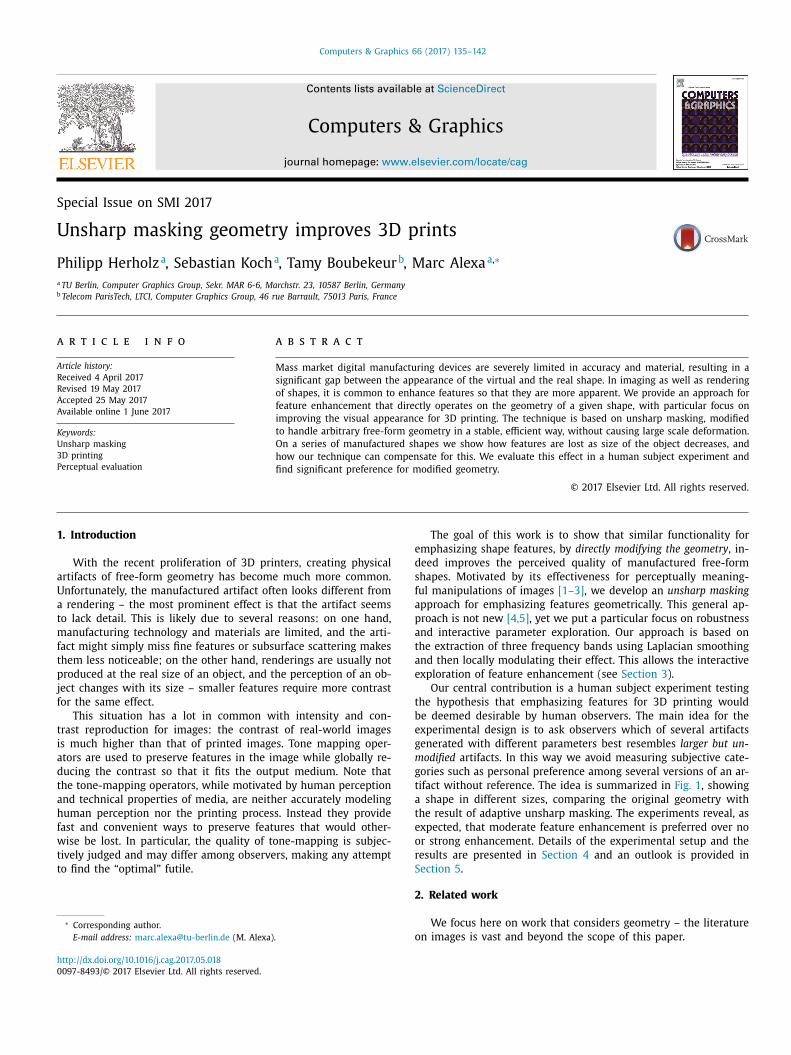
Computers & Graphics 66 (2017) 135–142
Contents lists available at ScienceDirect
Computers & Graphics
journal homepage: www.elsevier.com/locate/cag
Special Issue on SMI 2017
Unsharp masking geometry improves 3D prints
Philipp Herholz
a , Sebastian Koch
a , Tamy Boubekeur b , Marc Alexa
a , ∗
a TU Berlin, Computer Graphics Group, Sekr. MAR 6-6, Marchstr. 23, 10587 Berlin, Germany b Telecom ParisTech, LTCI, Computer Graphics Group, 46 rue Barrault, 75013 Paris, France
a r t i c l e i n f o
Article history:
Received 4 April 2017
Revised 19 May 2017
Accepted 25 May 2017
Available online 1 June 2017
Keywords:
Unsharp masking
3D printing
Perceptual evaluation
a b s t r a c t
Mass market digital manufacturing devices are severely limited in accuracy and material, resulting in a
significant gap between the appearance of the virtual and the real shape. In imaging as well as rendering
of shapes, it is common to enhance features so that they are more apparent. We provide an approach for
feature enhancement that directly operates on the geometry of a given shape, with particular focus on
improving the visual appearance for 3D printing. The technique is based on unsharp masking, modified
to handle arbitrary free-form geometry in a stable, efficient way, without causing large scale deformation.
On a series of manufactured shapes we show how features are lost as size of the object decreases, and
how our technique can compensate for this. We evaluate this effect in a human subject experiment and
find significant preference for modified geometry.
© 2017 Elsevier Ltd. All rights reserved.
1
a
U
a
t
m
f
t
p
j
f
t
i
a
d
t
a
h
f
w
t
t
e
d
s
f
a
p
a
t
a
e
t
b
e
g
m
g
t
a
t
e
o
r
S
h
0
. Introduction
With the recent proliferation of 3D printers, creating physical
rtifacts of free-form geometry has become much more common.
nfortunately, the manufactured artifact often looks different from
rendering – the most prominent effect is that the artifact seems
o lack detail. This is likely due to several reasons: on one hand,
anufacturing technology and materials are limited, and the arti-
act might simply miss fine features or subsurface scattering makes
hem less noticeable; on the other hand, renderings are usually not
roduced at the real size of an object, and the perception of an ob-
ect changes with its size – smaller features require more contrast
or the same effect.
This situation has a lot in common with intensity and con-
rast reproduction for images: the contrast of real-world images
s much higher than that of printed images. Tone mapping oper-
tors are used to preserve features in the image while globally re-
ucing the contrast so that it fits the output medium. Note that
he tone-mapping operators, while motivated by human perception
nd technical properties of media, are neither accurately modeling
uman perception nor the printing process. Instead they provide
ast and convenient ways to preserve features that would other-
ise be lost. In particular, the quality of tone-mapping is subjec-
ively judged and may differ among observers, making any attempt
o find the “optimal” futile.
∗ Corresponding author.
E-mail address: [email protected] (M. Alexa).
2
o
ttp://dx.doi.org/10.1016/j.cag.2017.05.018
097-8493/© 2017 Elsevier Ltd. All rights reserved.
The goal of this work is to show that similar functionality for
mphasizing shape features, by directly modifying the geometry , in-
eed improves the perceived quality of manufactured free-form
hapes. Motivated by its effectiveness for perceptually meaning-
ul manipulations of images [1–3] , we develop an unsharp masking
pproach for emphasizing features geometrically. This general ap-
roach is not new [4,5] , yet we put a particular focus on robustness
nd interactive parameter exploration. Our approach is based on
he extraction of three frequency bands using Laplacian smoothing
nd then locally modulating their effect. This allows the interactive
xploration of feature enhancement (see Section 3 ).
Our central contribution is a human subject experiment testing
he hypothesis that emphasizing features for 3D printing would
e deemed desirable by human observers. The main idea for the
xperimental design is to ask observers which of several artifacts
enerated with different parameters best resembles larger but un-
odified artifacts. In this way we avoid measuring subjective cate-
ories such as personal preference among several versions of an ar-
ifact without reference. The idea is summarized in Fig. 1 , showing
shape in different sizes, comparing the original geometry with
he result of adaptive unsharp masking. The experiments reveal, as
xpected, that moderate feature enhancement is preferred over no
r strong enhancement. Details of the experimental setup and the
esults are presented in Section 4 and an outlook is provided in
ection 5 .
. Related work
We focus here on work that considers geometry – the literature
n images is vast and beyond the scope of this paper.
136 P. Herholz et al. / Computers & Graphics 66 (2017) 135–142
Fig. 1. A 3D print of the Hand model (left) and successively smaller prints based
on the original geometry (upper row) or a modification based on adaptive unsharp
masking (lower row). The apparent loss of features with decreasing size is compen-
sated by the modification.
o
p
g
i
i
o
t
e
p
a
[
t
a
i
a
q
n
S
g
h
c
b
a
s
u
a
r
i
s
a
f
e
a
r
a
a
e
h
p
3
s
r
w
r
s
r
i
r
i
p
m
3
p
n
s
Feature enhancement for rendering geometry. There are a number
of effective techniques for emphasizing features of 3D geometry in
order to aid visual shape understanding. Most of these approaches
target rendering and, unfortunately, make use of the possibility to
alter the properties of the shape or the environment in ways that
are physically impossible, e.g. changing the albedo or surface nor-
mals based on geometric analysis [6,7] , or the light sources de-
pending on surface location [8–10] .
Unsharp masking has been used in the context of feature en-
hancement for rendering. Luft et al. [11] apply unsharp masking to
the depth buffer of a scene. Ritschel et al. [2] improve on this idea
by unsharp masking the image function using the geometry as the
parameter domain. This avoids artifacts near disocclusions. Even
though our approach aims to achieve similar results, our domain
(i.e. geometry) is different and this causes problems not present in
rendering (see Section 3 ).
Reliefs. Generating reliefs from geometry is a problem that is sim-
ilar to the image domain: the depths of the relief is a signal
that needs to be compressed, while the ground plane of the re-
lief serves as a parameter domain. Consequently, techniques for
the generation of reliefs are similar to tone-mapping methods [12] .
Schüller et al. [13] generalize relief generation by considering other
parameter domains and handling the case of discontinuities in
depths.
Feature enhancement. A common idea for feature enhancement is
to decompose the geometry into frequency bands and then amplify
the band corresponding to the desired features. This can be done
based on spectral decompositions [14,15] , which is unfortunately
quite expensive. Guskov et al. [16] suggest that a multi-resolution
decomposition could be used.
Instead of using a frequency decomposition other filters simi-
larly allow defining (and then enhancing) features. Kim and Varsh-
ney [4] base their definition on mesh saliency [17] , while Miao
et al. [18] develop their own measure. The mesh is then modified
such that saliency increases. It has recently been shown that com-
mon measure of geometric saliency fail to predict where humans
fixate on the actual 3D print [19] , so the advantage of basing fea-
ture enhancement on such measures (over other differential quan-
tities) is unclear.
A particular goal of ours is the enhancement of features while
preserving the overall shape as much as possible. This is a chal-
lenge that is not directly addressed in these approaches.
Optimization for 3D printing. Recently, optimizing the perceptual
quality of 3D prints has gained attention. Zhang et al. [20] focus
n the reduction of artifact caused by support structures and use
erceptual models to minimize them. Pintus et al. [5] modify the
eometry of the shape to counter the effects of a particular print-
ng technology, in their case powder-based 3D printing. Their goal
s similar to ours in that the dominant problem of this technol-
gy is loss of resolution. Our approach differs in that it is agnostic
o the printing technology and rather provides a technique that is
asily adapted to different settings.
Besides the methods that optimize the perceived quality of a
rint, there are also approaches that optimize the print quality by
ddressing problems of a specific printing technology. Alexa et al.
21] achieve higher accuracy prints by optimally adapting the layer
hickness of FDM and SLA prints. Zhou and Chen [22] increase the
ccuracy and resolution of SLA prints by finding the optimal mask
mage for each printed layer. In comparison, our approach does not
im at improving the objective quality but rather the perceived
uality of prints. It is therefore agnostic the actual printing tech-
ology and much simpler to realize.
hape-preserving geometry processing. As mentioned, one of our
oals is to preserve the geometry as much as possible while en-
ancing the features. This goal of shape preservation has also been
onsidered in smoothing, which is related as unsharp masking is
ased on reversing a smoothing operator. Smoothing methods usu-
lly minimize the surface area (i.e. mean curvature flow) so the
hape tends to shrink. While it is easy to adjust the global vol-
me (by scaling) it is more difficult to preserve the shape. Avail-
ble methods incorporate a term for local volume loss [23–25] that
equires an iterative solution even for moderate levels of smooth-
ng. In contrast, our approach is based on simple implicit Laplacian
moothing.
Compared to gradient domain techniques [26] our approach
llows exploring different parameter settings without the need
or repeatedly optimizing or solving a system of equations, thus
nabling interactive exploration on very large meshes. Work on
nisotropic smoothing [27–29] aims at smoothing surfaces while
etaining defining features. Using these enhanced smoothing oper-
tors to define frequency bands is potentially useful in our context
nd constitutes a promising direction for future work.
Our main contribution lies in utilizing established methods to
nable intuitive and fast improvement of 3D prints. The conducted
uman subject experiment shows that the approach is an appro-
riate solution for this purpose.
. Adaptive unsharp masking
The goal of our method is to modify the geometry of free-form
hapes so that 3D prints of the shape are visually closer to the
esult expected from the virtual version of the shape. In particular
hen printing in small size, features will be lost due to the limited
esolution of common manufacturing devices as well as subsurface
cattering.
We strongly believe that any method can only be of practical
elevance if it is robust with respect to the quality and size of the
nput mesh. In addition, the effect should depend only on few pa-
ameters and it should be possible to explore this parameter space
nteractively. Our proposed approach that provides these desirable
roperties is a locally adaptive filter based on the idea of unsharp
asking.
.1. Unsharp masking background
In its simplest form unsharp masking of 2D images can be im-
lemented as a linear filter that boosts high frequencies of the sig-
al. Even though the filter only pronounces edges, the human vi-
ual cortex creates the illusion that complete features have been
P. Herholz et al. / Computers & Graphics 66 (2017) 135–142 137
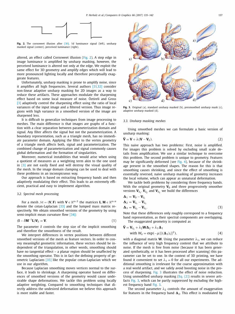
Fig. 2. The cornsweet illusion after [30] . 1d luminance signal (left), unsharp
masked signal (center), perceived luminance (right).
a
i
p
s
m
g
i
n
r
e
[
v
g
s
m
t
s
b
a
o
c
g
a
i
t
t
a
c
3
d
s
s
T
a
s
v
d
h
t
o
u
f
e
s
a
r
i
Fig. 3. Original (a), standard unsharp masked (b), presmoothed unsharp mask (c),
adaptive unsharp masked (d).
3
u
V
T
F
t
t
m
a
s
e
t
W
v
�
�
�
N
b
V
w
t
n
a
r
f
d
a
c
U
f
e
f
ltered, an effect called Cornsweet illusion ( Fig. 2 ). A step edge in
mage luminance is amplified by unsharp masking, however, the
erceived luminance is altered not only at the edge. We exploit the
ame effect for 3D geometry and amplify edges which will lead to
ore pronounced lighting locally and therefore perceptually exag-
erate features.
Unfortunately, unsharp masking is prone to amplify noise, since
t amplifies all high frequencies. Several authors [31,32] consider
on-linear adaptive unsharp masking for 2D images as a way to
educe these artifacts. These approaches modulate the sharpening
ffect based on some local measure of noise. Öztireli and Gross
3] adaptively control the sharpening effect using the ratio of local
ariances of the input image and a filtered version. Thus image re-
ions with high variance in a smoothed version of the image are
harpened less.
It is difficult to generalize techniques from image processing to
eshes. The main difference is that images are graphs of a func-
ion with a clear separation between parameterization domain and
ignal. Any filter affects the signal but not the parameterization. A
oundary representation, such as a triangle mesh, has no immedi-
te parameter domain. Applying the filter to the vertex geometry
f a triangle mesh affects both, signal and parameterization. The
ombined change of parameterization and signal commonly causes
lobal deformation and the formation of singularities.
Moreover, numerical instabilities that would arise when using
quotient of measures as a weighting term akin to the one used
n [3] are not easily fixed and will destroy the visual quality of
he mesh. In the image domain clamping can be used to deal with
hese problems in an inconspicuous way.
Our approach is based on extracting frequency bands and then
daptively modulating their effect. This leads to an extremely effi-
ient, practical and easy to implement algorithm.
.2. Spectral mesh processing
For a mesh M = (V , F ) with V ∈ R
n ×3 the matrices L , M ∈ R
n ×n
enote the cotan-Laplacian [33] and the lumped mass matrix re-
pectively. We obtain smoothed versions of the geometry by using
emi-implicit mean curvature flow [34] :
(I − δM
−1 L ) V δ = V . (1)
he parameter δ controls the step size of the implicit smoothing
nd therefore the smoothness of the result.
We interpret differences in vertex positions between different
moothed versions of the mesh as feature vectors. In order to con-
ey meaningful geometric information, these vectors should be in-
ependent of the triangulation, in other words, smoothing should
ave no tangential effect – a planar region should be unaffected by
he smoothing operator. This is in fact the defining property of ge-
metric Laplacians [35] like the popular cotan-Laplacian which we
se in our algorithm.
Because Laplacian smoothing moves vertices normal to the sur-
ace, it leads to shrinkage. A sharpening operator based on differ-
nces of smoothed versions of the geometry would cause unde-
irable shape deformations. We tackle this problem using locally
daptive weighting. Compared to smoothing techniques that di-
ectly address the undesired deformation we believe this approach
s more stable and faster.
.3. Unsharp masking meshes
Using smoothed meshes we can formulate a basic version of
nsharp masking:
˜ = V + λ(V − V δ ) . (2)
his naive approach has two problems: First, noise is amplified.
or images this problem is solved by excluding small scale de-
ails from amplification. We use a similar technique to overcome
his problem. The second problem is unique to geometry. Features
ay be significantly deformed (see Fig. 4 ), because of the shrink-
ge present in the smoothed shapes. The reason for this is that
moothing causes shrinking, and since the effect of smoothing is
ssentially reversed, naive unsharp masking of geometry increases
he local volume, which can appear as unnatural deformation.
We tackle both problems by considering three frequency bands.
ith the original geometry V 0 and three progressively smoother
ersions V δ1 , V δ2
and V δ3 we build the differences
1 = V 0 − V δ1
2 = V δ1 − V δ2
3 = V δ2 − V δ3
. (3)
ote that these differences only roughly correspond to a frequency
and representation, as their spectral components are overlapping.
The exaggerated geometry is computed as
˜ = V δ2
+ λ2 W�2 + λ1 �1
with W ii = exp (−μ|| (�3 ) i || 2 ) , (4)
ith a diagonal matrix W . Using the parameter λ1 , we can reduce
he influence of very high frequency content that we attribute to
oise. If the mesh is free from noise (because it has been gener-
ted synthetically, or it has been processed after scanning) this pa-
ameter can be set to one. In the context of 3D printing, we have
ound it convenient to set λ1 = 0 for all our experiments. The ad-
itional smoothing is irrelevant for the coarse approximation with
real world artifact, and we safely avoid boosting noise in the pro-
ess of sharpening. Fig. 3 illustrates the effect of noise reduction.
sing unmodified unsharp masking ( Eq. (2) ) results in severe arti-
acts Fig. 3 , which can be partly suppressed by excluding the high-
st frequency band Fig. 3 .
The second parameter λ2 controls the amount of exaggeration
or features in the frequency band � . This effect is modulated by
2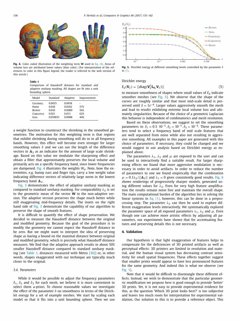
138 P. Herholz et al. / Computers & Graphics 66 (2017) 135–142
Fig. 4. Color coded illustration of the weighting term W used in Eq. (4) . Areas of
volume loss are attributed lower values (blue color). (For interpretation of the ref-
erences to color in this figure legend, the reader is referred to the web version of
this article.)
Table 1
Comparison of Hausdorff distance for standard and
adaptive unsharp masking. All shapes are fit into a unit
bounding sphere.
Model Standard Adaptive Improvement
Golfball 0.0015 0.0018 -
Hand 0.018 0.0102 57%
Bunny 0.016 0.0089 56%
Gargoyle 0.021 0.013 62%
Igea 0.019831 0.0088 44%
Fig. 5. Dirichlet energy at different smoothing levels controlled by the parameter δ
in (1) .
D
E
t
s
c
s
a
m
t
p
t
a
s
c
w
p
b
e
e
o
μ
s
i
t
T
l
c
f
t
t
r
t
4
c
p
r
t
t
f
F
f
r
3
t
a
i
a weight function to counteract the shrinking in the smoothed ge-
ometries. The motivation for this weighting term is that regions
that exhibit shrinking during smoothing will do so in all frequency
bands. However, this effect will become even stronger for larger
smoothing values δ and we can use the length of the difference
vectors in �3 as an indicator for the amount of large scale shrink-
age. Based on this value we modulate the sharpening effect and
obtain a filter that approximately preserves the local volume and
primarily acts on a specific frequency band, since lower frequencies
are dampened. Fig. 4 illustrates the weights W ii . Note, how the ex-
tremities, e.g. bunny ears and finger tips, carry a low weight value
indicating difference vectors of relatively large norm in the lowest
frequency band �3 .
Fig. 3 demonstrates the effect of adaptive unsharp masking as
compared to standard unsharp masking. For comparability λ2 is set
to the geometric mean of the vector W in the non-adaptive ver-
sion. The adaptive version preserves the shape much better while
still exaggerating mid-frequency details. The insets on the right
hand side of Fig. 3 demonstrate the capability of our algorithm to
preserve the shape of smooth features.
It is difficult to quantify the effect of shape preservation. We
decided to measure the Hausdorff distance between the original
and modified geometry. Because the goal of the procedure is to
modify the geometry we cannot expect the Hausdorff distance to
be zero. But we might want to interpret the idea of preserving
shape as having a bound on the maximal distance between original
and modified geometry, which is precisely what Hausdorff distance
measures. We find that the adaptive approach results in about 50%
smaller Hausdorff distance compared to standard unsharp mask-
ing (see Table 1 , distances measured with Metro [36] ) or, in other
words, shapes exaggerated with our technique are typically much
closer to the original.
3.4. Parameters
While it would be possible to adjust the frequency parameters
δ1 , δ2 and δ3 for each mesh, we believe it is more convenient to
select them a-priori. To choose reasonable values we investigate
the effect of the parameter δ on smoothness in terms of the Dirich-
let energy for a set of example meshes. We start by scaling each
model so that it fits into a unit bounding sphere. Then we use
irichlet energy
d (V δ ) = || diag (V
T δ L V δ V δ ) || (5)
o measure smoothness of shapes where small values of E d indicate
moother meshes (see Fig. 5 ). We observe that the shape of the
urves are roughly similar and that most mid-scale detail is pre-
erved until δ = 1 e −4 . Larger values aggressively smooth the mesh
nd lead to results exhibiting extreme local volume loss and ulti-
ately singularities. Because of the choice of a geometric Laplacian
his behavior is independent of combinatorics and mesh resolution.
Based on these observations, we suggest to set the smoothing
arameters to δ1 = 0 . 5 10 −5 , δ2 = 10 −5 , δ3 = 10 −4 . These parame-
ers tend to select a frequency band of mid scale features that
re well separated from noise while also not resulting in aggres-
ive smoothing. All examples in this paper are generated with this
hoice of parameters. If necessary, they could be changed and we
ould suggest to use analysis based on Dirichlet energy as ex-
lained above.
The parameters λ1 , λ2 and μ are exposed to the user and can
e used to interactively find a suitable result. For larger sharp-
ning effects we found that more aggressive modulation is nec-
ssary in order to avoid artifacts. In order to reduce the number
f parameters to one we found empirically that the combination
= 0 . 1 λ2 / || �3 || and λ1 = 0 gives consistently good results. Fig. 6
hows renderings of progressively sharper models, generated us-
ng different values for λ2 . Even for very high feature amplifica-
ion the results remain noise free and maintain the overall shape.
he main computational burden of the algorithm lies in solving the
inear systems in Eq. (1) , however, this can be done in a prepro-
essing step. The parameter λ2 can then be used to explore dif-
erent exaggeration levels interactively. We systematically explored
he parameter space of all exposed parameters λ1 , λ2 and μ. Even
hough one can achieve more artistic effects by adjusting all pa-
ameters, our experiments have shown that for accentuating fea-
ures and preserving details this is not necessary.
. Validation
Our hypothesis is that light exaggeration of features helps to
ompensate for the deficiencies of 3D printed artifacts as well as
erceptual effects: 3D printers are limited in resolution and mate-
ial, and the human visual system has decreasing contrast sensi-
ivity for small spatial frequencies. These effects together suggest
hat smaller prints would appear to have less pronounced features
or the same geometry. And indeed this is what we observe (see
ig. 1 ).
Note that it would be difficult to disentangle these different ef-
ects. Instead, we wish to demonstrate that the particular geomet-
ic modification we propose here is good enough to provide ‘better’
D prints. Yet, it is not easy to provide experimental evidence for
his, as the question ‘Which 3D print looks best?’ is too subjective
nd leaves too much room for interpretation for experimental val-
dation. Our solution to this is to provide a reference object. This
P. Herholz et al. / Computers & Graphics 66 (2017) 135–142 139
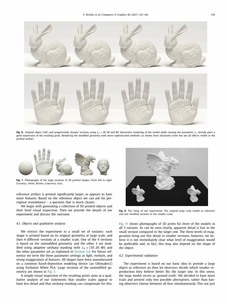
Fig. 6. Original object (left) and progressively sharper versions using λ2 = 20 , 40 and 80. Interactive rendering of the model while varying the parameter λ2 already gives a
good impression of the resulting print. Rendering the modified geometry with more sophisticated methods (as shown here) illustrates some but not all effects visible in the
printed artifact.
Fig. 7. Photographs of the large versions of 3D printed shapes. From left to right:
Golfball, Hand, Bunny, Gargoyle, Igea .
r
m
c
t
e
4
s
t
i
i
t
e
s
o
u
o
i
h
Fig. 8. The setup of one experiment. The original large scale model as reference
and two minified versions in the smaller scale.
F
a
s
g
l
b
t
4
o
p
t
t
i
eference artifact is printed significantly larger, so appears to have
ore features. Based on the reference object we can ask for per-
eptual resemblance – a question that is much clearer.
We begin with generating a collection of 3D printed objects and
heir brief visual inspection. Then we provide the details of our
xperiment and discuss the outcome.
.1. Objects and qualitative analysis
We restrict the experiment to a small set of variants: each
hape is printed based on its original geometry at large scale, and
hen 4 different versions at a smaller scale. One of the 4 versions
s based on the unmodified geometry, and the other 3 are mod-
fied using adaptive unsharp masking with λ2 = { 10 , 20 , 40 } and
he other parameter set as explained in Section 3.4 . For future ref-
rence we term the three parameter settings as light , medium , and
trong exaggeration of features. All shapes have been manufactured
n a common fused-deposition modeling device (an Ultimaker2)
sing Verbatim White PLA. Large versions of the unmodified ge-
metry are shown in Fig. 7 .
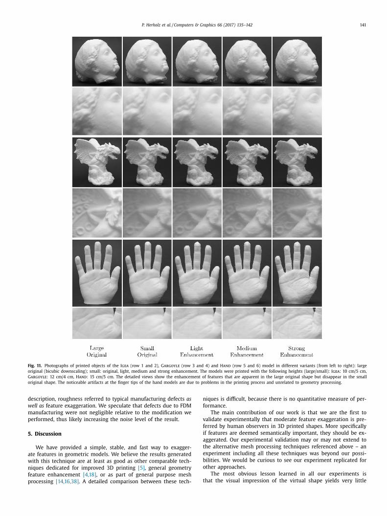
A simple visual inspection of the resulting prints aims at a qual-
tative analysis of our statements that smaller scales appear to
ave less detail and that unsharp masking can compensate for this.
ig. 11 shows photographs of 3D prints for three of the models in
ll 5 variants. As can be seen clearly, apparent detail is lost in the
mall version compared to the larger one. The three levels of exag-
eration bring out this detail in smaller versions, however, we be-
ieve it is not immediately clear what level of exaggeration would
e preferable and, in fact, this may also depend on the shape of
he object.
.2. Experimental validation
The experiment is based on our basic idea to provide a large
bject as reference an then let observers decide which smaller re-
roduction they believe better fits the larger one. In this sense,
he large model serves as ‘ground truth’. We decided to have more
rials and present only two possible alternatives, rather than hav-
ng observers choose between all four simultaneously. This not just
140 P. Herholz et al. / Computers & Graphics 66 (2017) 135–142
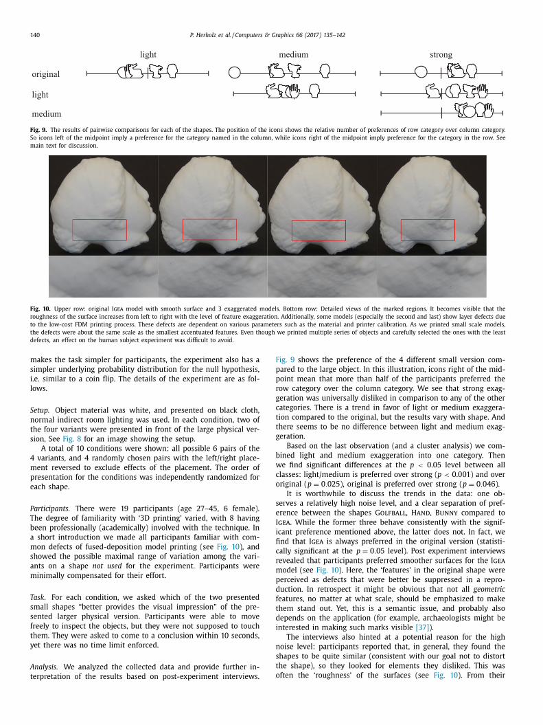
Fig. 9. The results of pairwise comparisons for each of the shapes. The position of the icons shows the relative number of preferences of row category over column category.
So icons left of the midpoint imply a preference for the category named in the column, while icons right of the midpoint imply preference for the category in the row. See
main text for discussion.
Fig. 10. Upper row: original Igea model with smooth surface and 3 exaggerated models. Bottom row: Detailed views of the marked regions. It becomes visible that the
roughness of the surface increases from left to right with the level of feature exaggeration. Additionally, some models (especially the second and last) show layer defects due
to the low-cost FDM printing process. These defects are dependent on various parameters such as the material and printer calibration. As we printed small scale models,
the defects were about the same scale as the smallest accentuated features. Even though we printed multiple series of objects and carefully selected the ones with the least
defects, an effect on the human subject experiment was difficult to avoid.
F
p
p
r
g
c
t
t
g
b
w
c
o
s
e
I
i
fi
c
r
m
p
d
f
t
d
i
n
s
t
o
makes the task simpler for participants, the experiment also has a
simpler underlying probability distribution for the null hypothesis,
i.e. similar to a coin flip. The details of the experiment are as fol-
lows.
Setup. Object material was white, and presented on black cloth,
normal indirect room lighting was used. In each condition, two of
the four variants were presented in front of the large physical ver-
sion, See Fig. 8 for an image showing the setup.
A total of 10 conditions were shown: all possible 6 pairs of the
4 variants, and 4 randomly chosen pairs with the left/right place-
ment reversed to exclude effects of the placement. The order of
presentation for the conditions was independently randomized for
each shape.
Participants. There were 19 participants (age 27–45, 6 female).
The degree of familiarity with ‘3D printing’ varied, with 8 having
been professionally (academically) involved with the technique. In
a short introduction we made all participants familiar with com-
mon defects of fused-deposition model printing (see Fig. 10 ), and
showed the possible maximal range of variation among the vari-
ants on a shape not used for the experiment. Participants were
minimally compensated for their effort.
Task. For each condition, we asked which of the two presented
small shapes “better provides the visual impression” of the pre-
sented larger physical version. Participants were able to move
freely to inspect the objects, but they were not supposed to touch
them. They were asked to come to a conclusion within 10 seconds,
yet there was no time limit enforced.
Analysis. We analyzed the collected data and provide further in-
terpretation of the results based on post-experiment interviews.
ig. 9 shows the preference of the 4 different small version com-
ared to the large object. In this illustration, icons right of the mid-
oint mean that more than half of the participants preferred the
ow category over the column category. We see that strong exag-
eration was universally disliked in comparison to any of the other
ategories. There is a trend in favor of light or medium exaggera-
ion compared to the original, but the results vary with shape. And
here seems to be no difference between light and medium exag-
eration.
Based on the last observation (and a cluster analysis) we com-
ined light and medium exaggeration into one category. Then
e find significant differences at the p < 0.05 level between all
lasses: light/medium is preferred over strong ( p < 0.001) and over
riginal ( p = 0 . 025 ), original is preferred over strong ( p = 0 . 046 ).
It is worthwhile to discuss the trends in the data: one ob-
erves a relatively high noise level, and a clear separation of pref-
rence between the shapes Golfball, Hand, Bunny compared to
gea . While the former three behave consistently with the signif-
cant preference mentioned above, the latter does not. In fact, we
nd that Igea is always preferred in the original version (statisti-
ally significant at the p = 0 . 05 level). Post experiment interviews
evealed that participants preferred smoother surfaces for the Igea
odel (see Fig. 10 ). Here, the ‘features’ in the original shape were
erceived as defects that were better be suppressed in a repro-
uction. In retrospect it might be obvious that not all geometric
eatures, no matter at what scale, should be emphasized to make
hem stand out. Yet, this is a semantic issue, and probably also
epends on the application (for example, archaeologists might be
nterested in making such marks visible [37] ).
The interviews also hinted at a potential reason for the high
oise level: participants reported that, in general, they found the
hapes to be quite similar (consistent with our goal not to distort
he shape), so they looked for elements they disliked. This was
ften the ‘roughness’ of the surfaces (see Fig. 10 ). From their
P. Herholz et al. / Computers & Graphics 66 (2017) 135–142 141
Fig. 11. Photographs of printed objects of the Igea (row 1 and 2), Gargoyle (row 3 and 4) and Hand (row 5 and 6) model in different variants (from left to right): large
original (bicubic downscaling); small: original, light, medium and strong enhancement. The models were printed with the following heights (large/small): Igea : 10 cm/5 cm,
Gargoyle : 12 cm/4 cm, Hand : 15 cm/5 cm. The detailed views show the enhancement of features that are apparent in the large original shape but disappear in the small
original shape. The noticeable artifacts at the finger tips of the hand models are due to problems in the printing process and unrelated to geometry processing.
d
w
m
p
5
a
w
n
f
p
n
f
v
f
i
a
t
e
b
o
t
escription, roughness referred to typical manufacturing defects as
ell as feature exaggeration. We speculate that defects due to FDM
anufacturing were not negligible relative to the modification we
erformed, thus likely increasing the noise level of the result.
. Discussion
We have provided a simple, stable, and fast way to exagger-
te features in geometric models. We believe the results generated
ith this technique are at least as good as other comparable tech-
iques dedicated for improved 3D printing [5] , general geometry
eature enhancement [4,18] , or as part of general purpose mesh
rocessing [14,16,38] . A detailed comparison between these tech-
iques is difficult, because there is no quantitative measure of per-
ormance.
The main contribution of our work is that we are the first to
alidate experimentally that moderate feature exaggeration is pre-
erred by human observers in 3D printed shapes. More specifically
f features are deemed semantically important, they should be ex-
ggerated. Our experimental validation may or may not extend to
he alternative mesh processing techniques referenced above – an
xperiment including all these techniques was beyond our possi-
ilities. We would be curious to see our experiment replicated for
ther approaches.
The most obvious lesson learned in all our experiments is
hat the visual impression of the virtual shape yields very little
142 P. Herholz et al. / Computers & Graphics 66 (2017) 135–142
[
[
[
[
[
[
[
[
information regarding the visual impression of the real shape –
so screen based experiments are not very helpful in analyzing the
usefulness of geometry processing methods for 3D printing.
References
[1] Krawczyk G, Myszkowski K, Seidel H-P. Contrast restoration by adaptive coun-tershading. Comput Graph Forum 2007;26(3):581–90. doi: 10.1111/j.1467-8659.
2007.01081.x .
[2] Ritschel T , Smith K , Ihrke M , Grosch T , Myszkowski K , Seidel H-P . 3d un-sharp masking for scene coherent enhancement. ACM Trans Graph 2008;27(3)
:90:1–90:8 . [3] Öztireli AC , Gross M . Perceptually based downscaling of images. ACM Trans
Graph 2015;34(4):77:1–77:10 . [4] Kim Y , Varshney A . Persuading visual attention through geometry. IEEE Trans
Visual Comput Graph 2008;14(4):772–82 .
[5] Pintus R, Gobbetti E, Cignoni P, Scopigno R. Shape enhancement for rapid pro-totyping. Vis Comput 2010;26(6):831–40. doi: 10.10 07/s0 0371- 010- 0488- 0 .
[6] Miller G. Efficient algorithms for local and global accessibility shading. In: Pro-ceedings of the 21st Annual Conference on Computer Graphics and Interactive
Techniques. New York, NY, USA: ACM; 1994. p. 319–26. ISBN 0-89791-667-0.doi: 10.1145/192161.192244 .
[7] Cignoni P, Scopigno R, Tarini M. A simple normal enhancement technique for
interactive non-photorealistic renderings. Comput Graph 2005;29(1):125–33.doi: 10.1016/j.cag.2004.11.012 .
[8] Lee CH, Hao X, Varshney A. Geometry-dependent lighting. IEEE Trans VisualComput Graph 2006;12(2):197–207. doi: 10.1109/TVCG.2006.30 .
[9] Rusinkiewicz S, Burns M, DeCarlo D. Exaggerated shading for depictingshape and detail. ACM Trans Graph 2006;25(3):1199–205. doi: 10.1145/1141911.
1142015 .
[10] Vergne R, Pacanowski R, Barla P, Granier X, Schlick C. Light warping for en-hanced surface depiction. ACM Trans Graph 2009;28(3) :25:1–25:8. doi: 10.
1145/1531326.1531331 . [11] Luft T, Colditz C, Deussen O. Image enhancement by unsharp masking
the depth buffer. ACM Trans Graph 2006;25(3):1206–13. doi: 10.1145/1141911.1142016 .
[12] Weyrich T, Deng J, Barnes C, Rusinkiewicz S, Finkelstein A. Digital bas-relief
from 3d scenes. ACM Trans Graph 2007;26(3). doi: 10.1145/1276377.1276417 . [13] Schüller C, Panozzo D, Sorkine-Hornung O. Appearance-mimicking surfaces.
ACM Trans Graph 2014;33(6):216:1–216:10. doi: 10.1145/2661229.2661267 . [14] Zhang H, Van Kaick O, Dyer R. Spectral mesh processing. Comput Graph Forum
2010;29(6):1865–94. doi: 10.1111/j.1467-8659.2010.01655.x . [15] Vallet B, Levy B. Spectral geometry processing with manifold harmonics. Com-
put Graphics Forum 2008. doi: 10.1111/j.1467-8659.2008.01122.x . [16] Guskov I, Sweldens W, Schröder P. Multiresolution signal processing for
meshes. In: Proceedings of the 26th Annual Conference on Computer Graph-
ics and Interactive Techniques. New York, NY, USA: ACM Press/Addison-WesleyPublishing Co.; 1999. p. 325–34. ISBN 0-201-48560-5. doi: 10.1145/311535.
311577 . [17] Lee CH, Varshney A, Jacobs DW. Mesh saliency. ACM Trans Graph
2005;24(3):659–66. doi: 10.1145/1073204.1073244 . [18] Miao Y-W , Feng J-Q , Wang J-R , Pajarola R . A multi-channel salience based
detail exaggeration technique for 3d relief surfaces. J Comput Sci Technol
2012;27(6):1100–9 .
[19] Wang X, Lindlbauer D, Lessig C, Maertens M, Alexa M. Measuring the visualsalience of 3d printed objects. IEEE Comput Graph Appl 2016;36(4):46–55.
doi: 10.1109/MCG.2016.47 . [20] Zhang X , Le X , Panotopoulou A , Whiting E , Wang CCL . Perceptual models of
preference in 3d printing direction. ACM Trans Graph 2015;34(6) . [21] Alexa M, Hildebrand K, Lefebvre S. Optimal discrete slicing. ACM Trans Graph
2017;36(1):12:1–12:16. doi: 10.1145/2999536 . 22] Zhou C, Chen Y. Additive manufacturing based on optimized mask video pro-
jection for improved accuracy and resolution. J Manuf Process 2012;14(2):107–
18 . 10.1016/j.jmapro.2011.10.002 23] Liu X, Bao H, Shum H-Y, Peng Q. A novel volume constrained smooth-
ing method for meshes. Graph Models 2002;64(3):169–82. doi: 10.1006/gmod.2002.0576 .
[24] Sousa FS, Castelo A, Nonato LG, Mangiavacchi N, Cuminato JA. Localvolume-conserving free surface smoothing. Commun Numer Meth Eng
2007;23(2):109–20. doi: 10.1002/cnm.886 .
25] Rypl D, Nerad J. Volume preserving smoothing of triangular isotropic three-dimensional surface meshes. Adv Eng Softw 2016;101(C):3–26. doi: 10.1016/j.
advengsoft.2016.01.016 . 26] Chuang M , Rusinkiewicz S , Kazhdan M . Gradient-domain processing of meshes.
J Comput Graph Tech 2016;5(4):44–55 . [27] Clarenz U, Diewald U, Rumpf M. Anisotropic geometric diffusion in surface
processing. In: Proceedings Visualization 20 0 0. VIS 20 0 0 (Cat. No.0 0CH37145);
20 0 0. p. 397–405. doi: 10.1109/VISUAL.20 0 0.885721 . [28] Tasdizen T , Whitaker R , Burchard P , Osher S . Geometric surface smoothing via
anisotropic diffusion of normals. In: Proceedings of the Conference on Visual-ization. Washington, DC, USA: IEEE Computer Society; 2002. p. 125–32. ISBN
0-7803-7498-3 . 29] Bajaj CL, Xu G. Anisotropic diffusion of surfaces and functions on surfaces. ACM
Trans Graph 2003;22(1):4–32. doi: 10.1145/588272.588276 .
[30] Purves D , Shimpi A , Lotto RB . An empirical explanation of the cornsweet effect.J Neurosci 1999;19(19):8542–51 .
[31] Ramponi G . A cubic unsharp masking technique for contrast enhancement. Sig-nal Process 1998;67(2):211–22 .
32] Polesel A , Ramponi G , Mathews V . Image enhancement via adaptive unsharpmasking. IEEE Trans Image Process 20 0 0;9(3):505–10 .
[33] Pinkall U , Polthier K . Computing discrete minimal surfaces and their conju-
gates. Exper Math 1993;2:15–36 . [34] Desbrun M , Meyer M , Schröder P , Barr AH . Implicit fairing of irregular meshes
using diffusion and curvature flow. In: Proceedings of the 26th Annual Con-ference on Computer Graphics and Interactive Techniques. New York, NY, USA:
ACM Press/Addison-Wesley Publishing Co.; 1999. p. 317–24 . [35] Wardetzky M , Mathur S , Kälberer F , Grinspun E . Discrete laplace operators:
No free lunch. In: Proceedings of the Fifth Eurographics Symposium on Geom-
etry Processing. Aire-la-Ville, Switzerland, Switzerland: Eurographics Associa-tion; 2007. p. 33–7. ISBN 978-3-905673-46-3 .
36] Cignoni P , Rocchini C , Scopigno R . Metro: measuring error on simplified sur-faces. Comput Graph Forum 1998;17(2):167–74 .
[37] Kolomenkin M, Shimshoni I, Tal A. Demarcating curves for shape illustration.ACM Trans Graph 2008;27(5):157:1–157:9. doi: 10.1145/1409060.1409110 .
38] Taubin G . A signal processing approach to fair surface design. In: Proceedingsof the 22nd Annual Conference on Computer Graphics and Interactive Tech-
niques. New York, NY, USA: ACM; 1995. p. 351–8. ISBN 0-89791-701-4 .

![[TechnicalNote] - Gifu Universityunsharp masking, a standard tool in image processing [12]. Thus, one may naturally surmise that images edge-enhanced by unsharp masking on digital](https://img.pdfslide.net/doc/110x75/6004340e290cee283c6620bf/technicalnote-gifu-unsharp-masking-a-standard-tool-in-image-processing-12.jpg)