Embed Size (px)
Citation preview
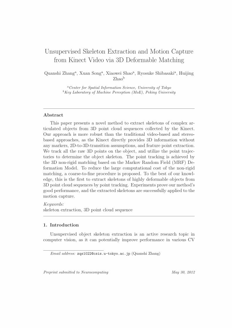
Unsupervised Skeleton Extraction and Motion Capture
from Kinect Video via 3D Deformable Matching
Quanshi Zhanga, Xuan Songa, Xiaowei Shaoa, Ryosuke Shibasakia, HuijingZhaob
aCenter for Spatial Information Science, University of TokyobKey Laboratory of Machine Perception (MoE), Peking University
Abstract
This paper presents a novel method to extract skeletons of complex ar-ticulated objects from 3D point cloud sequences collected by the Kinect.Our approach is more robust than the traditional video-based and stereo-based approaches, as the Kinect directly provides 3D information withoutany markers, 2D-to-3D-transition assumptions, and feature point extraction.We track all the raw 3D points on the object, and utilize the point trajec-tories to determine the object skeleton. The point tracking is achieved bythe 3D non-rigid matching based on the Markov Random Field (MRF) De-formation Model. To reduce the large computational cost of the non-rigidmatching, a coarse-to-fine procedure is proposed. To the best of our knowl-edge, this is the first to extract skeletons of highly deformable objects from3D point cloud sequences by point tracking. Experiments prove our method’sgood performance, and the extracted skeletons are successfully applied to themotion capture.
Keywords:skeleton extraction, 3D point cloud sequence
1. Introduction
Unsupervised object skeleton extraction is an active research topic incomputer vision, as it can potentially improve performance in various CV
Email address: [email protected] (Quanshi Zhang)
Preprint submitted to Neurocomputing May 30, 2012
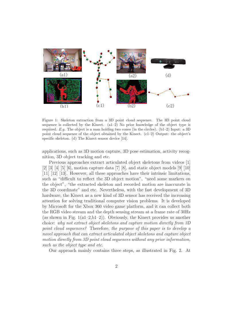
Figure 1: Skeleton extraction from a 3D point cloud sequence. The 3D point cloudsequence is collected by the Kinect. (a1–2) No prior knowledge of the object type isrequired. E.g. The object is a man holding two cones (in the circles). (b1–2) Input: a 3Dpoint cloud sequence of the object obtained by the Kinect. (c1–2) Output: the object’sspecific skeleton. (d) The Kinect sensor device [14].
applications, such as 3D motion capture, 3D pose estimation, activity recog-nition, 3D object tracking and etc.
Previous approaches extract articulated object skeletons from videos [1][2] [3] [4] [5] [6], motion capture data [7] [8], and static object models [9] [10][11] [12] [13]. However, all these approaches have their intrinsic limitations,such as “difficult to reflect the 3D object motion”, “need some markers onthe object”, “the extracted skeleton and recorded motion are inaccurate inthe 3D coordinate” and etc. Nevertheless, with the fast development of 3Dhardware, the Kinect as a new kind of 3D sensor has received the increasingattention for solving traditional computer vision problems. It is developedby Microsoft for the Xbox 360 video game platform, and it can collect boththe RGB video stream and the depth sensing stream at a frame rate of 30Hz(as shown in Fig. 1(a1–2,b1–2)). Obviously, the Kinect provides us anotherchoice: why not extract object skeletons and capture motion directly from 3Dpoint cloud sequences? Therefore, the purpose of this paper is to develop anovel approach that can extract articulated object skeletons and capture objectmotion directly from 3D point cloud sequences without any prior information,such as the object type and etc.
Our approach mainly contains three steps, as illustrated in Fig. 2. At
2
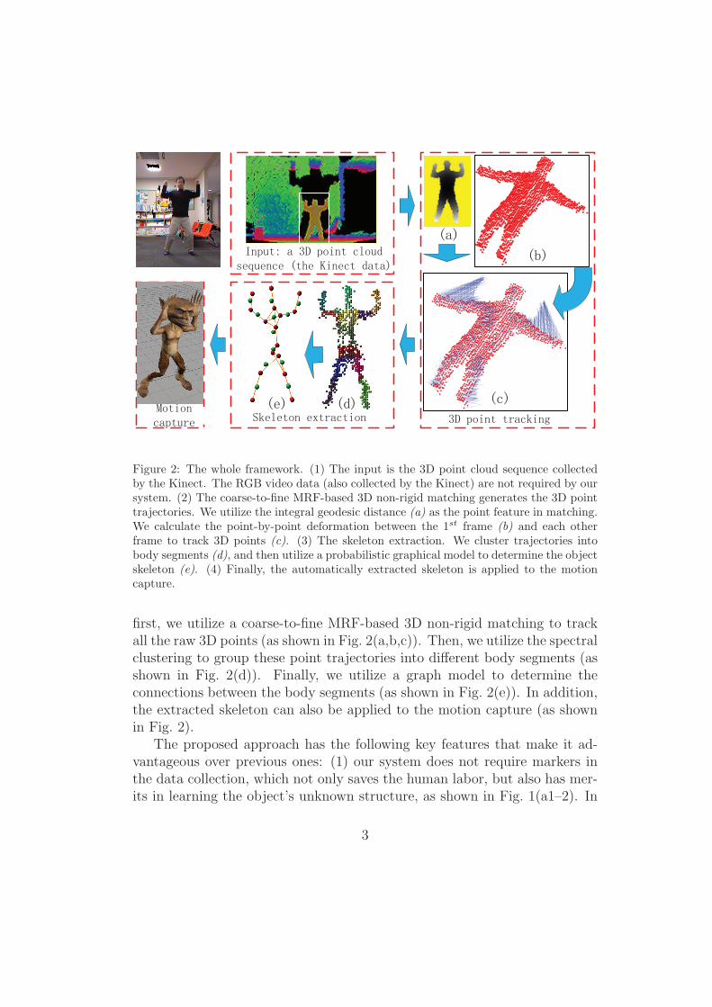
Figure 2: The whole framework. (1) The input is the 3D point cloud sequence collectedby the Kinect. The RGB video data (also collected by the Kinect) are not required by oursystem. (2) The coarse-to-fine MRF-based 3D non-rigid matching generates the 3D pointtrajectories. We utilize the integral geodesic distance (a) as the point feature in matching.We calculate the point-by-point deformation between the 1st frame (b) and each otherframe to track 3D points (c). (3) The skeleton extraction. We cluster trajectories intobody segments (d), and then utilize a probabilistic graphical model to determine the objectskeleton (e). (4) Finally, the automatically extracted skeleton is applied to the motioncapture.
first, we utilize a coarse-to-fine MRF-based 3D non-rigid matching to trackall the raw 3D points (as shown in Fig. 2(a,b,c)). Then, we utilize the spectralclustering to group these point trajectories into different body segments (asshown in Fig. 2(d)). Finally, we utilize a graph model to determine theconnections between the body segments (as shown in Fig. 2(e)). In addition,the extracted skeleton can also be applied to the motion capture (as shownin Fig. 2).
The proposed approach has the following key features that make it ad-vantageous over previous ones: (1) our system does not require markers inthe data collection, which not only saves the human labor, but also has mer-its in learning the object’s unknown structure, as shown in Fig. 1(a1–2). In
3

contrast, for the marker-based approach, people usually locate markers onsome key parts of the articulated object (such as the joints and body seg-ment centers), according to their subjective understanding. The subjectiveunderstanding can bring priori errors to the unknown structure learning. (2)Compared to the static-model-based approaches, our approach utilizes themotion information to obtain accurate object segments. Moreover, it doesnot require well-constructed 3D models. (3) Different from the video-based3D reconstruction, the Kinect directly provides the object’s spatial structurewithout any shape deformation assumptions. What’s more, in order to ob-tain the body segments’ motion, we can directly track all the raw 3D pointswithout feature point extraction. Therefore, the 3D point tracking does notsuffer from monotonous colors and illumination changes as the video-basedtracking.
The main contributions of this paper can be summarized as follows: (1)To our best knowledge, this is the first work that extracts skeletons of com-plex articulated objects directly from 3D point cloud sequences without priorinformation by point-level tracking. Our algorithm provides a global segmen-tation of the object body segments, which is robust to small intra-segmentdeformation. (2) We propose an efficient coarse-to-fine framework to trackthe 3D points based on the MRF Deformation Model. The coarse-to-fine s-trategy greatly reduces the tracking’s time/memory cost. To our best knowl-edge, this is the first work to track all the raw 3D points of a deformableobject without any transformation assumptions.
The rest of this paper is organized as follows: The related work is brieflyreviewed in the following section. Section 3 presents the coarse-to-fine 3Dpoint tracking and Section 4 presents the skeleton extraction. The experi-ments and results are presented in Section 5. Finally, the paper is concludedin Section 6.
2. Related work
Many previous approaches extract skeletons from videos (Ross et al. [1][2], Yan et al. [3] [4], Tresadern et al. [5], and Ramanan et al. [6]). [1][2] [3] [4] utilize the KLT tracker [15] to get feature trajectories. Howev-er, these methods require sufficient feature points on some key parts of theobject for good performance, and the image-based tracking may suffer fromillumination changes.
4
Some vision-based methods utilize multiple cameras to obtain a dense 3Dpoint cloud sequence of the object, and then extract the object skeleton fromthe 3D sequence. Compared to the pure video-based methods, these meth-ods obtain the object’s 3D structure and spatial motion more directly andaccurately. Cheung et al. [16] reconstruct a model of the kinematic structureand appearance of a person from the visual hull. However, the model recon-struction is based on the person’s free motion, and they determine the jointpoint one by one by allowing only one body part to move in each step. Chuet al. [17] obtain volume sequences by multiple cameras, extract the skeletoncurve from each frame, and then utilize the skeleton curves to determine thekinematic model. They do not track all the points over frames, so the systemmay face difficulties when the shape of some object parts (such as a roundbowl) is not suitable for the principle curve extraction.
Kirk et al. [7] and Sturm et al. [8] directly get 3D point trajectories byusing the motion capture system. The articulated body segments, as well astheir motion, are learned from the marker trajectories.
Sturm et al. [18] utilize the depth data to learn the articulated models ofcabinet doors and drawers with the rectangle detection.
The approaches mentioned above all extract object structure based onthe motion information. [3] [5] utilize a factorization method to discover therotation axis between two object body segments, and [8] generates a low-dimension parameter-free representation of the articulated object to extractthe object structure. They assume the body segments are rigid. Therefore,these methods are not robust to the non-rigid body segments with complexintra-segment deformation. In contrast, some approaches in [7] [1] [2] [4] andours just cluster trajectories into the body segments, which is based on thefact that the distance between two points on the same rigid body segment isconstant. The clustering provides a global solution to the body segmentation,which is robust to small intra-segment deformation in theory.
Other approaches [9] [10] [11] extract skeletons from static 3D or 2Dmodels. However, they only use the topological and geometrical information,and cannot segment the articulated object without motion cues. Aujay et al.[12] utilize a harmonic function to get anatomical information to improve theskeleton. Schaefer et al. [13] propose an example-based skeleton extraction,which requires several well-constructed 3D models in different poses.
Generally, the motion-based skeleton extraction method obtains an ar-ticulated skeleton, which represents the topological structure of the object[1] [2] [3] [4] [5] [19] [16] [7]. However, the skeleton extracted from the static
5
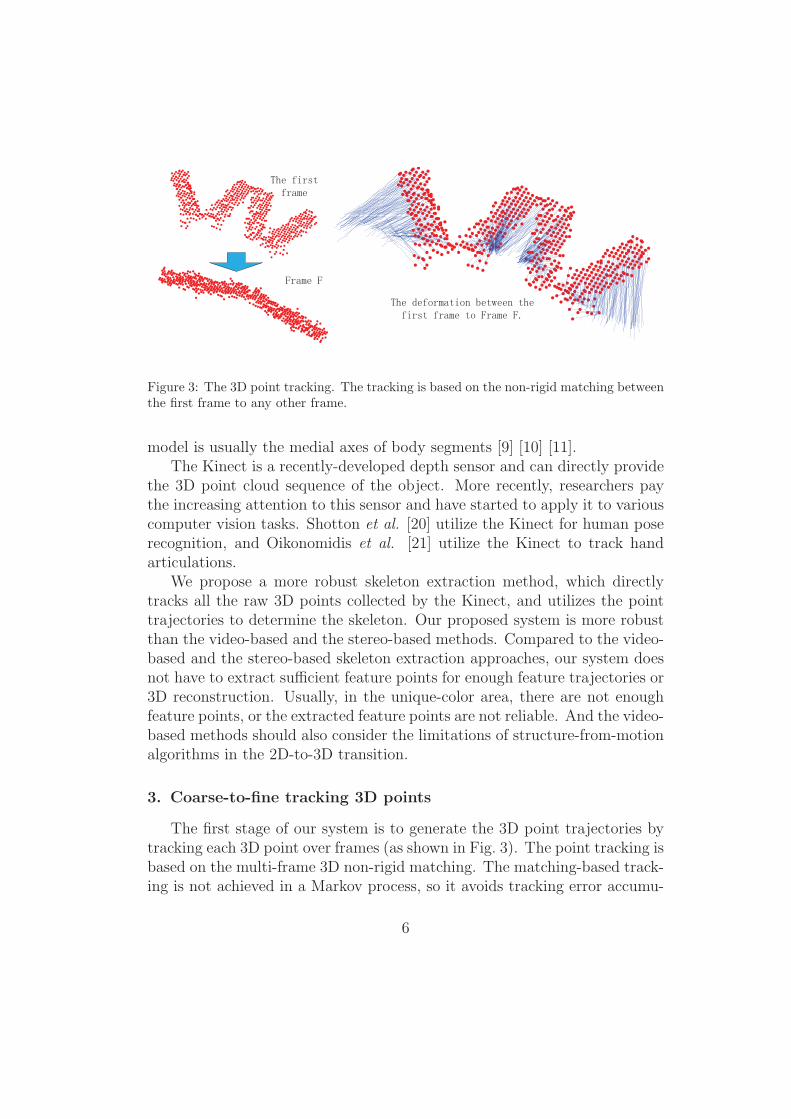
Figure 3: The 3D point tracking. The tracking is based on the non-rigid matching betweenthe first frame to any other frame.
model is usually the medial axes of body segments [9] [10] [11].The Kinect is a recently-developed depth sensor and can directly provide
the 3D point cloud sequence of the object. More recently, researchers paythe increasing attention to this sensor and have started to apply it to variouscomputer vision tasks. Shotton et al. [20] utilize the Kinect for human poserecognition, and Oikonomidis et al. [21] utilize the Kinect to track handarticulations.
We propose a more robust skeleton extraction method, which directlytracks all the raw 3D points collected by the Kinect, and utilizes the pointtrajectories to determine the skeleton. Our proposed system is more robustthan the video-based and the stereo-based methods. Compared to the video-based and the stereo-based skeleton extraction approaches, our system doesnot have to extract sufficient feature points for enough feature trajectories or3D reconstruction. Usually, in the unique-color area, there are not enoughfeature points, or the extracted feature points are not reliable. And the video-based methods should also consider the limitations of structure-from-motionalgorithms in the 2D-to-3D transition.
3. Coarse-to-fine tracking 3D points
The first stage of our system is to generate the 3D point trajectories bytracking each 3D point over frames (as shown in Fig. 3). The point tracking isbased on the multi-frame 3D non-rigid matching. The matching-based track-ing is not achieved in a Markov process, so it avoids tracking error accumu-
6
lation over frames. To match two specific frames, we extend the image-basedMRF Deformation Model proposed in [22] [23]. The time/memory cost tomatch a large number of 3D points is intolerable. Therefore, we utilize acoarse-to-fine strategy to reduce the searching range in matching.
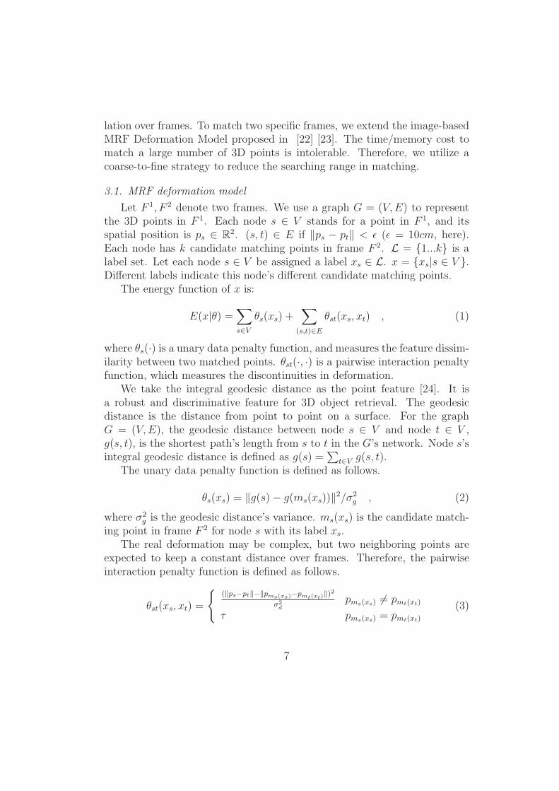
3.1. MRF deformation model
Let F 1, F 2 denote two frames. We use a graph G = (V,E) to representthe 3D points in F 1. Each node s ∈ V stands for a point in F 1, and itsspatial position is ps ∈ R
2. (s, t) ∈ E if ‖ps − pt‖ < ε (ε = 10cm, here).Each node has k candidate matching points in frame F 2. L = {1...k} is alabel set. Let each node s ∈ V be assigned a label xs ∈ L. x = {xs|s ∈ V }.Different labels indicate this node’s different candidate matching points.
The energy function of x is:
E(x|θ) =∑s∈V
θs(xs) +∑
(s,t)∈Eθst(xs, xt) , (1)
where θs(·) is a unary data penalty function, and measures the feature dissim-ilarity between two matched points. θst(·, ·) is a pairwise interaction penaltyfunction, which measures the discontinuities in deformation.
We take the integral geodesic distance as the point feature [24]. It isa robust and discriminative feature for 3D object retrieval. The geodesicdistance is the distance from point to point on a surface. For the graphG = (V,E), the geodesic distance between node s ∈ V and node t ∈ V ,g(s, t), is the shortest path’s length from s to t in the G’s network. Node s’sintegral geodesic distance is defined as g(s) =
∑t∈V g(s, t).
The unary data penalty function is defined as follows.
θs(xs) = ‖g(s)− g(ms(xs))‖2/σ2g , (2)
where σ2g is the geodesic distance’s variance. ms(xs) is the candidate match-
ing point in frame F 2 for node s with its label xs.The real deformation may be complex, but two neighboring points are
expected to keep a constant distance over frames. Therefore, the pairwiseinteraction penalty function is defined as follows.
θst(xs, xt) =
{(‖ps−pt‖−‖pms(xs)−pmt(xt)
‖)2σ2d
pms(xs) �= pmt(xt)
τ pms(xs) = pmt(xt)
(3)
7
������� ��� �������� � � �
������ �� ���� ���� ��������
���
����
��
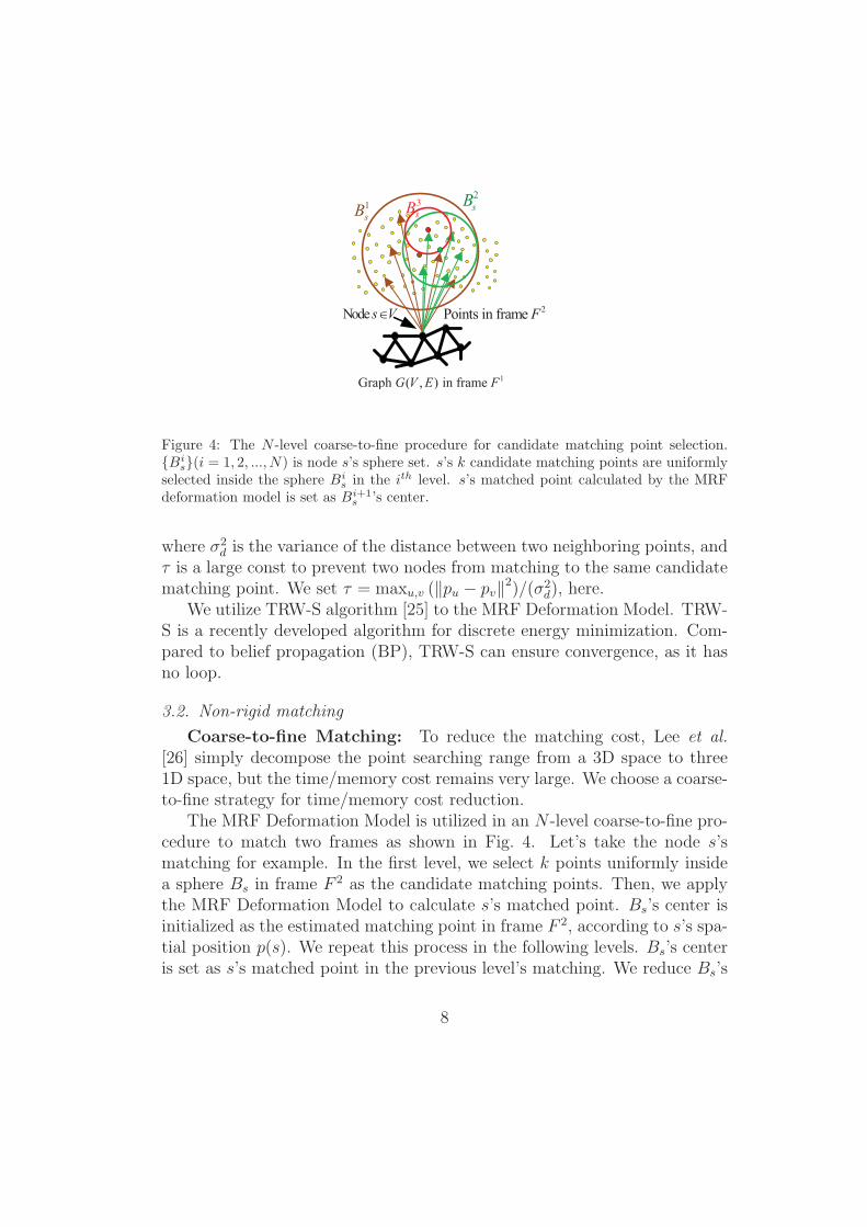
Figure 4: The N -level coarse-to-fine procedure for candidate matching point selection.{Bi
s}(i = 1, 2, ..., N) is node s’s sphere set. s’s k candidate matching points are uniformlyselected inside the sphere Bi
s in the ith level. s’s matched point calculated by the MRFdeformation model is set as Bi+1
s ’s center.
where σ2d is the variance of the distance between two neighboring points, and
τ is a large const to prevent two nodes from matching to the same candidatematching point. We set τ = maxu,v (‖pu − pv‖2)/(σ2
d), here.We utilize TRW-S algorithm [25] to the MRF Deformation Model. TRW-
S is a recently developed algorithm for discrete energy minimization. Com-pared to belief propagation (BP), TRW-S can ensure convergence, as it hasno loop.
3.2. Non-rigid matching
Coarse-to-fine Matching: To reduce the matching cost, Lee et al.[26] simply decompose the point searching range from a 3D space to three1D space, but the time/memory cost remains very large. We choose a coarse-to-fine strategy for time/memory cost reduction.
The MRF Deformation Model is utilized in an N -level coarse-to-fine pro-cedure to match two frames as shown in Fig. 4. Let’s take the node s’smatching for example. In the first level, we select k points uniformly insidea sphere Bs in frame F 2 as the candidate matching points. Then, we applythe MRF Deformation Model to calculate s’s matched point. Bs’s center isinitialized as the estimated matching point in frame F 2, according to s’s spa-tial position p(s). We repeat this process in the following levels. Bs’s centeris set as s’s matched point in the previous level’s matching. We reduce Bs’s
8
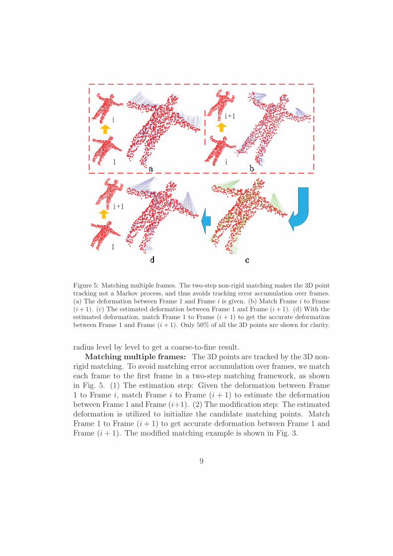
Figure 5: Matching multiple frames. The two-step non-rigid matching makes the 3D pointtracking not a Markov process, and thus avoids tracking error accumulation over frames.(a) The deformation between Frame 1 and Frame i is given. (b) Match Frame i to Frame(i+1). (c) The estimated deformation between Frame 1 and Frame (i+1). (d) With theestimated deformation, match Frame 1 to Frame (i + 1) to get the accurate deformationbetween Frame 1 and Frame (i+ 1). Only 50% of all the 3D points are shown for clarity.
radius level by level to get a coarse-to-fine result.Matching multiple frames: The 3D points are tracked by the 3D non-
rigid matching. To avoid matching error accumulation over frames, we matcheach frame to the first frame in a two-step matching framework, as shownin Fig. 5. (1) The estimation step: Given the deformation between Frame1 to Frame i, match Frame i to Frame (i + 1) to estimate the deformationbetween Frame 1 and Frame (i+1). (2) The modification step: The estimateddeformation is utilized to initialize the candidate matching points. MatchFrame 1 to Frame (i+ 1) to get accurate deformation between Frame 1 andFrame (i+ 1). The modified matching example is shown in Fig. 3.
9
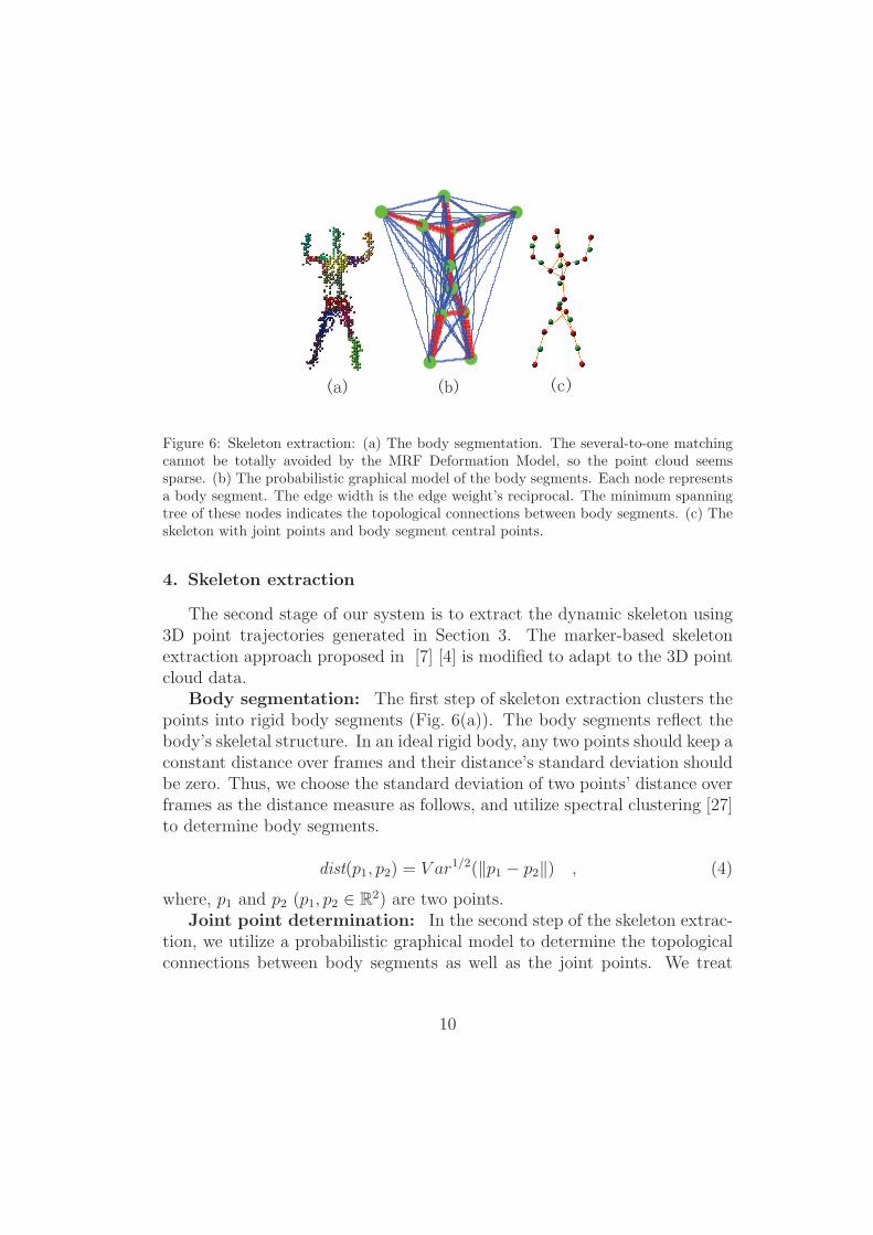
Figure 6: Skeleton extraction: (a) The body segmentation. The several-to-one matchingcannot be totally avoided by the MRF Deformation Model, so the point cloud seemssparse. (b) The probabilistic graphical model of the body segments. Each node representsa body segment. The edge width is the edge weight’s reciprocal. The minimum spanningtree of these nodes indicates the topological connections between body segments. (c) Theskeleton with joint points and body segment central points.
4. Skeleton extraction
The second stage of our system is to extract the dynamic skeleton using3D point trajectories generated in Section 3. The marker-based skeletonextraction approach proposed in [7] [4] is modified to adapt to the 3D pointcloud data.
Body segmentation: The first step of skeleton extraction clusters thepoints into rigid body segments (Fig. 6(a)). The body segments reflect thebody’s skeletal structure. In an ideal rigid body, any two points should keep aconstant distance over frames and their distance’s standard deviation shouldbe zero. Thus, we choose the standard deviation of two points’ distance overframes as the distance measure as follows, and utilize spectral clustering [27]to determine body segments.
dist(p1, p2) = V ar1/2(‖p1 − p2‖) , (4)
where, p1 and p2 (p1, p2 ∈ R2) are two points.
Joint point determination: In the second step of the skeleton extrac-tion, we utilize a probabilistic graphical model to determine the topologicalconnections between body segments as well as the joint points. We treat
10
each body segment as a node in a complete graph. The edge weight betweentwo body segments C1 and C2 is defined as follows.
WC1,C2 = maxi∈F
minp1,i∈c1,i,p2,i∈c2,i
‖p1,i − p2,i‖ , (5)
where, F is the frame label set, c1,i, c2,i are the point sets of body segmentsC1 and C2 in Frame i. C1 = {c1,i}, C2 = {c2,i}.
The two body segments with small edge weight have large possibilityto be connected. We generate the graph’s minimum spanning tree as thetopological connections between body segments. Fig. 6(b) shows the bodysegment graph and the minimum spanning tree. We select the joint pointof two connected body segments from either body segment’s point set. Thejoint point should be the one with the shortest average distance to the otherbody segment over frames.
Skeleton generation: The last step of skeleton extraction draws skele-ton based on joint points (Fig. 6(c)). To represent the body segment withmultiple joint points, we draw a skeleton between each pair of the joint points.For the body segment with a single joint point (e.g. the lower leg and thehead), we connect the joint point to its farthest point in this segment.
5. Experiment
To show the performance of our system, we used the Kinect to collect four3D point cloud sequences, and extracted four skeletons from these sequencesrespectively. Sequence 1 is a man, Sequence 2 is a man holding two cones,Sequence 3 is a box chain and Sequence 4 is a vacuum cleaner. Meanwhile,we further collected the 3D data of a human upper body by using both theKinect (Sequence 5) and the marker-based motion capture system (markertrajectories), in order to compare our method with the marker-based mo-tion capture. To measure the coarse-to-fine strategy’s performance in thetime/memory cost reduction, we conducted five experiments on Sequence 5,and the 3D point matching with five sets of different parameters was per-formed in these experiments.
Body segment centers and the extracted skeleton’s joint points are usual-ly the articulated object’s key points. Therefore, these automatically learnedcenters and joint points can take place of the markers in the motion capture,as in Experiment 1 (Section 5.2). We can extract the skeleton of any irregulararticulated object or unknown object, as no prior knowledge or constrains are
11
required in our approach. E.g. the cones holding in man’s hands are success-fully extracted as two specific body segments (Section 5.3) and the skeletonof the box chain with a strange shape can also be extracted. (Section 5.5).
In this section, we will provide the details about these experiments andquantitative comparisons.
5.1. Kinect
The Kinect sensor is a new active depth sensor developed by Microsoft forthe Xbox 360 video game platform. The Kinect contains an infrared projectorand a monochrome CMOS camera. Kinect interprets depth information fromcontinuously-projected infrared structure rays [14]. The depth estimation isbased on the time-of-flight of the infrared rays.
The Kinect collects both RGB video stream and relatively accurate depthsensing stream at a frame rate of 30Hz. The depth sensing video uses a VGAresolution of 640× 480 pixels with 11-bit depth (2048 sensitivity levels).
5.2. Experiment 1: A man
Data: We utilized the Kinect to collect the 3D point sequence of a man,as shown in Fig. 7(a1–a4). The Kinect collected both the 3D point sequenceand the RGB video, and our approach only required the 3D point sequence.The 3D point sequence had 22 frames with the frame rate of 5 fps. Thedepth image’s resolution in each frame was 160 × 120. In each frame, therewere 1526 points on the object on average.
Tracking 3D points: Some body segments moved fast, such as theupper arms and the lower legs. Sometimes, their translations between twoneighboring frames reached 50cm. Thus, we had to search each point’s can-didate matching points within a radius of 50cm in the next frame. The totalnumber of candidate matching points reached more than 400 in some frames.The non-rigid matching problem was an MRF optimization problem as shownin Section 3.1. Without the coarse-to-fine procedure in matching, each nodewould have at most 400 label choices, which cost too much computation timeand memory.
Therefore, in the estimation step (Section 3.2), we applied an 8-levelcoarse-to-fine procedure to match two neighboring frames empirically. Ineach level, at most 20 candidate matching points were selected. The sphereradiuses in the 8 levels decreased from 50cm to 4cm exponentially. (Thesphere is the range to select candidate matching points for a node; see Sec-tion 3.2). Inside the smallest sphere (the radius is 4cm), there were at most
12
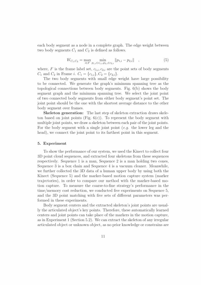
Figure 7: Experimental result of “a man”. (a1–a4) show the human’s poses in 4 videoframes. Lines in (b1–b4) show the deformations from the first frame to the other frames.Only 50% of the 3D points are shown for clarity. (c1–c4) The left figure shows the extractedskeleton with joint points and body segment central points. The right figure shows thecorresponding motion capture result.
11 (< 20) points to select. Thus, each node could be matched to any pointwithin 50cm in theory.
In the modification step of multiple-frame matching (Section 3.2), wematched the first frame to each frame based on the estimated deformation.Therefore, the candidate matching point’s searching range was not so largeas in the estimation step. We matched the first frame to each frame in a6-level coarse-to-fine procedure. In each level, we also selected 20 candi-date matching points, and the sphere radiuses decreased from 25cm to 4cmexponentially.
Fig. 7(b1–b4) shows the modified deformation between the first frame tothe other frames.
The skeleton and the motion capture: The man’s extracted skele-ton had 12 body segments: the head, the chest, the waist, the buttocks, twoupper arms, two lower arms, two upper legs and two lower legs. This bodysegmentation agreed with the common sense. The joint points and body
13
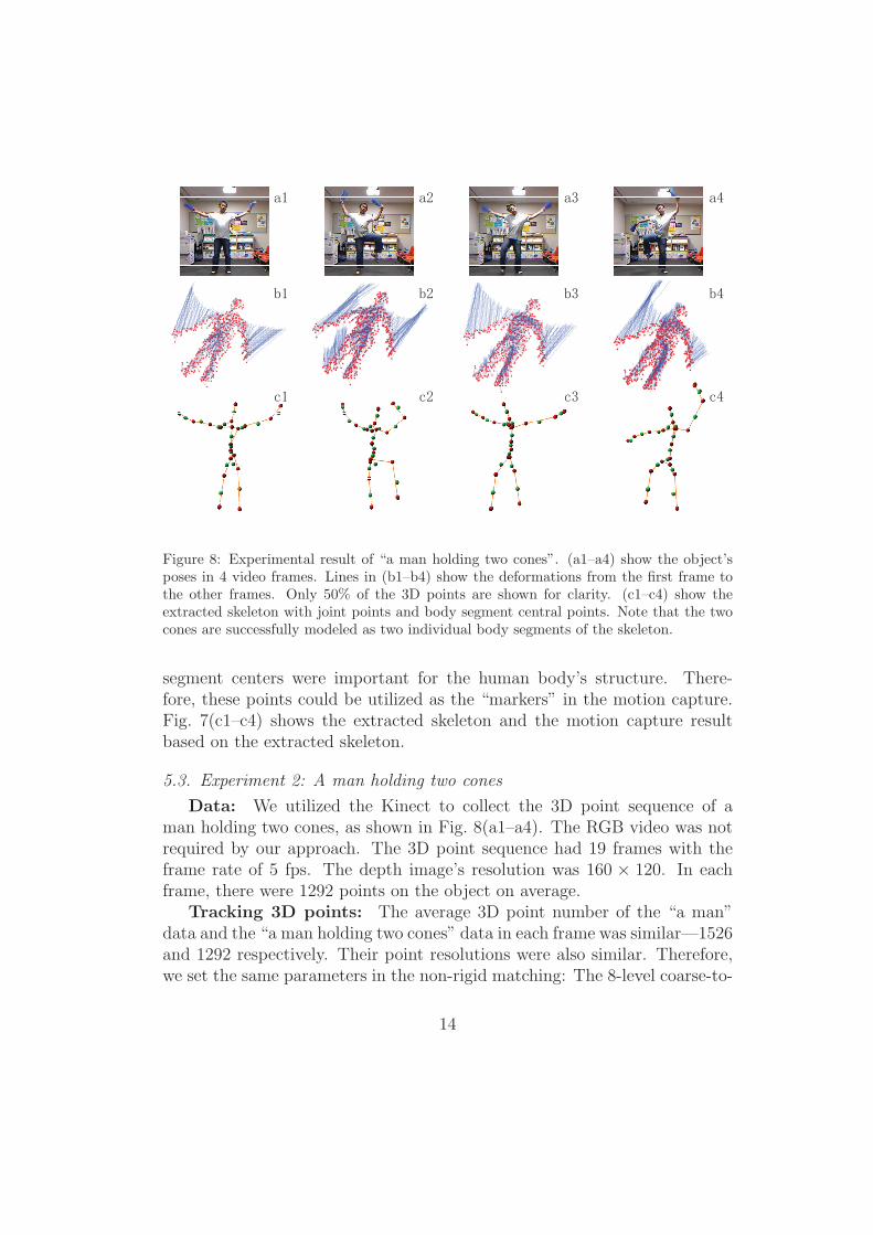
Figure 8: Experimental result of “a man holding two cones”. (a1–a4) show the object’sposes in 4 video frames. Lines in (b1–b4) show the deformations from the first frame tothe other frames. Only 50% of the 3D points are shown for clarity. (c1–c4) show theextracted skeleton with joint points and body segment central points. Note that the twocones are successfully modeled as two individual body segments of the skeleton.
segment centers were important for the human body’s structure. There-fore, these points could be utilized as the “markers” in the motion capture.Fig. 7(c1–c4) shows the extracted skeleton and the motion capture resultbased on the extracted skeleton.
5.3. Experiment 2: A man holding two cones
Data: We utilized the Kinect to collect the 3D point sequence of aman holding two cones, as shown in Fig. 8(a1–a4). The RGB video was notrequired by our approach. The 3D point sequence had 19 frames with theframe rate of 5 fps. The depth image’s resolution was 160 × 120. In eachframe, there were 1292 points on the object on average.
Tracking 3D points: The average 3D point number of the “a man”data and the “a man holding two cones” data in each frame was similar—1526and 1292 respectively. Their point resolutions were also similar. Therefore,we set the same parameters in the non-rigid matching: The 8-level coarse-to-
14
fine matching procedure in the estimation step, and the 6-level coarse-to-finematching procedure in the modification step.
Fig. 8(b1–b4) shows the modified deformation between the first frame toother frames.
The skeleton: The extracted skeleton had 15 body segments: twocones, the head, the right shoulder, the chest, the waist, the buttocks, t-wo upper arms, two lower arms, two upper legs and two lower legs, as shownin Fig. 8(c1–c4). The cones were successfully modeled as two individual bodysegments. The skeleton contained a right shoulder but no left shoulder. Theasymmetric skeleton was due to the asymmetric motion in the data.
5.4. Experiment 3: A box chain
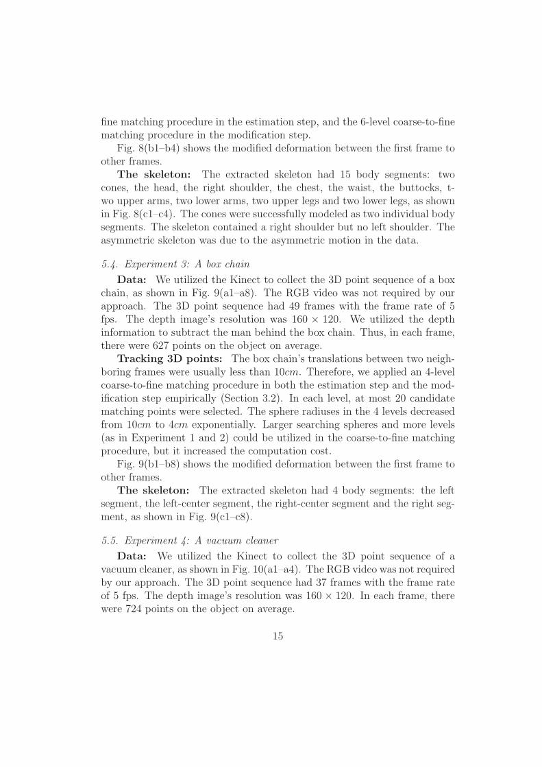
Data: We utilized the Kinect to collect the 3D point sequence of a boxchain, as shown in Fig. 9(a1–a8). The RGB video was not required by ourapproach. The 3D point sequence had 49 frames with the frame rate of 5fps. The depth image’s resolution was 160 × 120. We utilized the depthinformation to subtract the man behind the box chain. Thus, in each frame,there were 627 points on the object on average.
Tracking 3D points: The box chain’s translations between two neigh-boring frames were usually less than 10cm. Therefore, we applied an 4-levelcoarse-to-fine matching procedure in both the estimation step and the mod-ification step empirically (Section 3.2). In each level, at most 20 candidatematching points were selected. The sphere radiuses in the 4 levels decreasedfrom 10cm to 4cm exponentially. Larger searching spheres and more levels(as in Experiment 1 and 2) could be utilized in the coarse-to-fine matchingprocedure, but it increased the computation cost.
Fig. 9(b1–b8) shows the modified deformation between the first frame toother frames.
The skeleton: The extracted skeleton had 4 body segments: the leftsegment, the left-center segment, the right-center segment and the right seg-ment, as shown in Fig. 9(c1–c8).
5.5. Experiment 4: A vacuum cleaner
Data: We utilized the Kinect to collect the 3D point sequence of avacuum cleaner, as shown in Fig. 10(a1–a4). The RGB video was not requiredby our approach. The 3D point sequence had 37 frames with the frame rateof 5 fps. The depth image’s resolution was 160 × 120. In each frame, therewere 724 points on the object on average.
15
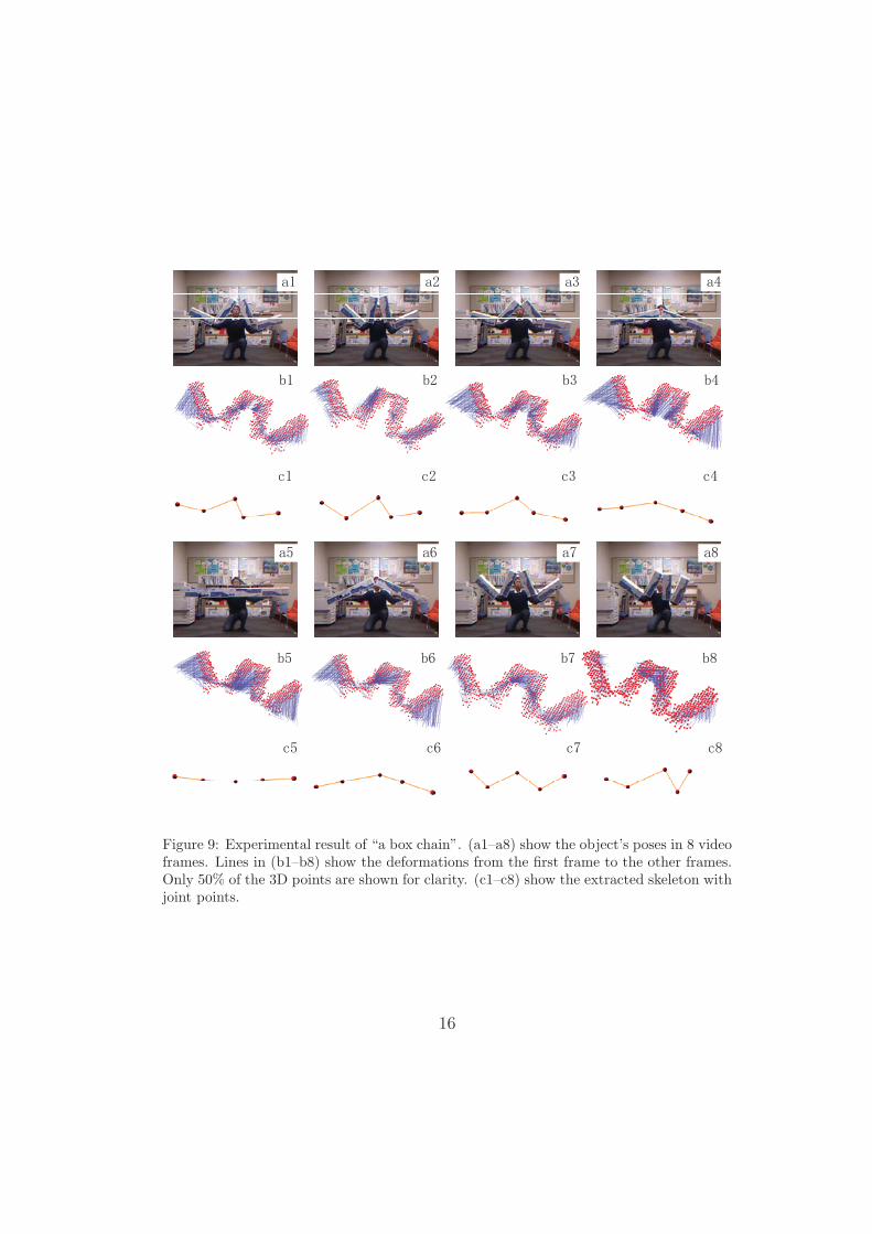
Figure 9: Experimental result of “a box chain”. (a1–a8) show the object’s poses in 8 videoframes. Lines in (b1–b8) show the deformations from the first frame to the other frames.Only 50% of the 3D points are shown for clarity. (c1–c8) show the extracted skeleton withjoint points.
16
Figure 10: Experimental result of “a vacuum cleaner”. (a1–a4) show the object’s poses in4 video frames. Lines in (b1–b4) show the deformations from the first frame to the otherframes. Only 50% of the 3D points are shown for clarity. Some matching errors exist inthe pipe and the stick, because the pipe and the stick are very thin and black, and thus,the point number is very small in these parts in some frames. (c1–c4) show the extractedskeleton with joint points.
Tracking 3D points: The vacuum cleaner’s translations between twoneighboring frames were usually less than 14cm. Therefore, we applied an5-level coarse-to-fine matching procedure in both the estimation step andthe modification step empirically (Section 3.2). In each level, at most 20candidate matching points were selected. The sphere radiuses in the 5 levelsdecreased from 14cm to 4cm exponentially. Larger searching spheres andmore levels (as in Experiment 1 and 2) could be utilized in the coarse-to-finematching procedure, but it increased the computation cost.
Fig. 10(b1–b4) shows the modified deformation between the first frameto other frames.
The skeleton: The extracted skeleton had 4 body segments, includingthe stick and the pipe, as shown in Fig. 10(c1–c4).
17
��
��
��
��
��
��
� � � � � � � �� �� �� �� �� �� �� �� �
� ������ ������������������ ������ ��� �������������� ������ ������������������ ������ ��� �������������� ������ ������������
�
��
��
��
��
��
��
��
�
� � � � � � � �� �� �� �� �� �� �� �� �
��������� �������������������������� ��� ���������������������� �������������������������� ��� ���������������������� ������������
��
��
��
��
��
��
� � � � � � � ������������������������������������������������������������������������
� ��� ���� �� � ������ �� � ����!�����������
�
���
���
���
���
��
� � � � � � � �� �� �� �� �� �� �� �� � � �� �� �� �� �� �� �� �� � � �� �� �� �� �� �� �� ��
��� ������������"���#������������
��
��
��
��
��
��
� � � � � � � �� �� �� �� �� �� �� �� � � �� ��
� ������ ������������������ ������ ��� �������������� ������ ������������������ ������ ��� �������������
��
��
��
��
��
��
� � � � � � � �� �� �� �� �� �� �� �� � � �� ��
��������� �������������������������� ��� ���������������������� �������������������������� ��� �������������
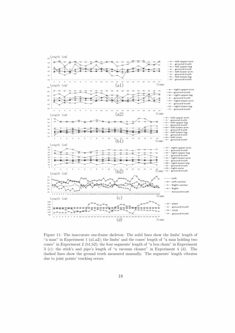
Figure 11: The inaccurate one-frame skeleton: The solid lines show the limbs’ length of“a man” in Experiment 1 (a1,a2); the limbs’ and the cones’ length of “a man holding twocones” in Experiment 2 (b1,b2); the four segments’ length of “a box chain” in Experiment3 (c); the stick’s and pipe’s length of “a vacuum cleaner” in Experiment 4 (d). Thedashed lines show the ground truth measured manually. The segments’ length vibratesdue to joint points’ tracking errors.
18
Segment Extracted Ground Accuracyname length length
A manleft upper arm 34.1 35.0 97.45%left upper leg 31.5 31.1 98.61%left lower arm 34.5 28.9 80.74%left lower leg 49.2 47.8 97.11%right upper arm 35.2 35 99.58%right upper leg 30.1 31.1 96.91%right lower arm 27.1 28.9 93.60%right lower leg 44.0 47.8 92.08%
A man holding two conesleft upper arm 32.9 39.1 84.10%left upper leg 32.4 29.8 91.15%left lower arm 32.6 27.1 79.41%left lower leg 58.5 57.0 97.33%left cone 27.6 29.4 94.03%right upper arm 48.4 39.1 76.27%right upper leg 13.6 29.8 45.58%right lower arm 25.9 27.1 95.64%right lower leg 67.8 57.0 81.10%right cone 27.6 29.4 94.00%
A box chainleft 44.6 47.0 94.85%left-center 65.0 47.0 61.76%right-center 43.3 47.0 92.18%right 50.5 47.0 92.57%
A vacuum cleanerpipe 109.0 129.3 84.3%stick 143.2 135.2 94.11%
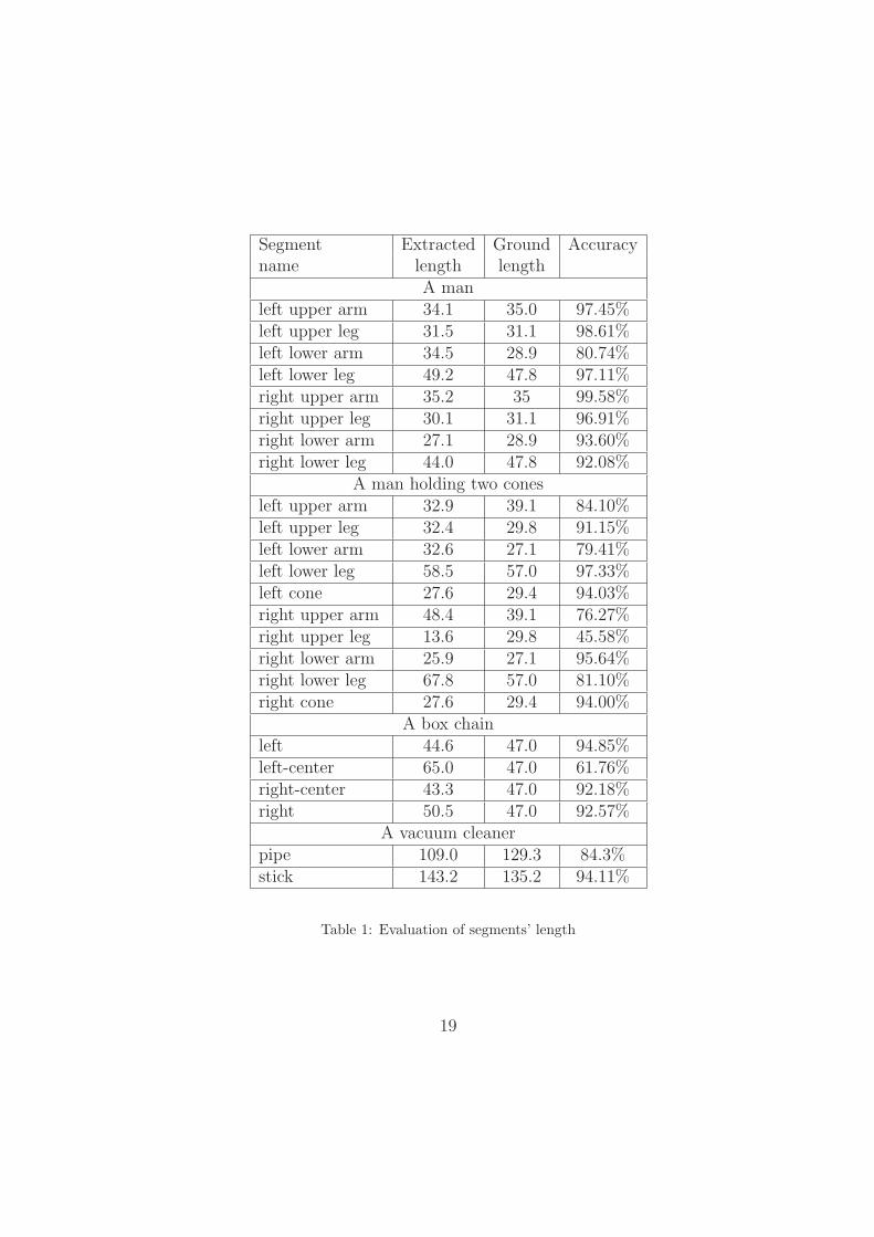
Table 1: Evaluation of segments’ length
19
5.6. Results and evaluation
To evaluate the extracted skeleton’s accuracy, we selected some semanti-cally correct body segments from the skeleton, and measured their real lengthmanually as the ground truth. We took the segment’s average length in allframes as the extracted length, and compared the extracted length with theground truth. The reason was that one-frame skeletons were inaccurate. Thesegments’ length in these skeletons were greatly affected by the joint points’tracking errors (as shown in Fig. 11).
However, there is no measurement to evaluate the correctness of a complexskeletal structure (such as the skeleton of human beings) for the followingtwo reasons: (1) one object can be subjectively divided into different numberof body segments. E.g. A person’s trunk can be considered as consisted ofthe chest, the waist and the buttocks, or just as one whole body segment. (2)We can use different skeletal structures to represent the same body segment.E.g. The person’s trunk can be represented as a rectangle, a stick, or a“X” shape. Intuitively, only the limbs and the cones in hands have only oneskeletal structure hypothesis—a stick.
In Experiment 1–2, our approach could not detect the axial rotations andtiny deformation on the wrist and the ankle, due to the data’s resolution andnoise. Thus, in the extracted skeleton, the hand was a part of the upper arm,and the foot (as well as the shoe) was a part of the lower leg. Therefore,the upper arm’s length was set as the distance from the elbow to the palm.The upper leg’s length was set as the distance from the crotch to the kneealong the inner thigh. The lower arm’s length was set as the distance fromthe axilla (the sleeve’s crotch) to the elbow. The lower leg’s length was setas the distance from the knee to the arch. Note that all the measurementwas done with the clothes, as the data utilized in the experiment was withclothes on. Therefore, for accuracy, we counted the wear’s thickness in themeasurement. The shoe elongated the lower leg. The clothes made the bodyfatter, which shortened the lower arm. The trousers made the crotch lowerand thus shortened the upper leg.
We admit that the anatomical length is a good measurement to evaluatethe skeleton of human beings. However, compared to the human-model-basedpose estimation, the unsupervised skeleton extraction’s potential applicationis to discover the “unknown” dynamic skeleton of any “unfamiliar” objectwithout any prior knowledge. Thus, we evaluate our algorithm by how muchthe extracted skeleton objectively reflect the actual object deformation and
20

the actual segment length in appearance. Therefore, the anatomical lengthis not utilized.
In Experiment 3, the box chain was successfully divided into four seg-ments. The segments’ extracted length and the real length were comparedfor evaluation. In Experiment 4, the vacuum cleaner was divided into foursegments, the pipe segment, the stick segment, the handle segment and thebox segment. As the handle segment’s length was greatly affected by thearm’s motion, and the box segment did not cover the whole body of the vac-uum cleaner after background subtraction, we just selected the pipe segmentand the stick segment as reliable segments for evaluation.
The segments’ extracted length in Experiment 1–4 is evaluated in Table 1.Generally, the unsupervised learned skeleton successfully reflects the ob-
ject’s true articulated structure. However, the automatically extracted skele-tal pose cannot be as accurate as the model-based pose estimation, and thereasons are summarized as follows: (1) The small intra-segment deformation(such as the changes of clothes’ wrinkles) brings errors to the body segmenta-tion. (2) The clothes smooth the sharp limbs motion, which makes it difficultto determine the joints’ positions. E.g. Crotches of trousers and sleeves s-mooth the motion of arms and legs. As a result, sometimes, the upper armscontain small parts of the chest, and the upper legs are shorter than usual.(3) Noise causes some small errors in the 3D non-rigid matching.
Although noise brings some error into the 3D point tracking, the error isnot accumulated over frames. Besides, our tracking is not robust to large oc-clusion. Only the 3D point cloud sequence without other information (suchas the RGB color) is not sensitive enough to detect the column-shape seg-ment’s axial rotation (E.g. arm’s axial rotation). We assume two points onthe same body segment should keep similar distances over frames, but theassumption fails when the expansion and contraction of the object size exist.E.g. A man is blowing a balloon.
5.7. Quantitative comparisons and evaluation
In this section, we utilized Sequence 5 to compare our method with themarker-based motion capture system. Moreover, we conducted the 3D pointmatching with five sets of different parameters to evaluate the coarse-to-finestrategy’s performance in the time/memory cost reduction.
Experimental settings: We utilized the Kinect to collect the 3D pointsequence of the upper body (Sequence 5), as shown in Fig. 13(a1–a5). TheRGB video was not required by our approach. The 3D point sequence was
21
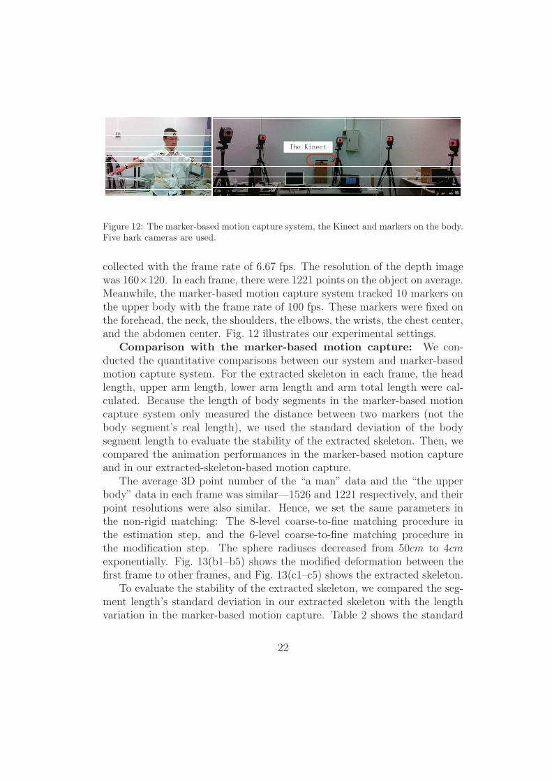
Figure 12: The marker-based motion capture system, the Kinect and markers on the body.Five hark cameras are used.
collected with the frame rate of 6.67 fps. The resolution of the depth imagewas 160×120. In each frame, there were 1221 points on the object on average.Meanwhile, the marker-based motion capture system tracked 10 markers onthe upper body with the frame rate of 100 fps. These markers were fixed onthe forehead, the neck, the shoulders, the elbows, the wrists, the chest center,and the abdomen center. Fig. 12 illustrates our experimental settings.
Comparison with the marker-based motion capture: We con-ducted the quantitative comparisons between our system and marker-basedmotion capture system. For the extracted skeleton in each frame, the headlength, upper arm length, lower arm length and arm total length were cal-culated. Because the length of body segments in the marker-based motioncapture system only measured the distance between two markers (not thebody segment’s real length), we used the standard deviation of the bodysegment length to evaluate the stability of the extracted skeleton. Then, wecompared the animation performances in the marker-based motion captureand in our extracted-skeleton-based motion capture.
The average 3D point number of the “a man” data and the “the upperbody” data in each frame was similar—1526 and 1221 respectively, and theirpoint resolutions were also similar. Hence, we set the same parameters inthe non-rigid matching: The 8-level coarse-to-fine matching procedure inthe estimation step, and the 6-level coarse-to-fine matching procedure inthe modification step. The sphere radiuses decreased from 50cm to 4cmexponentially. Fig. 13(b1–b5) shows the modified deformation between thefirst frame to other frames, and Fig. 13(c1–c5) shows the extracted skeleton.
To evaluate the stability of the extracted skeleton, we compared the seg-ment length’s standard deviation in our extracted skeleton with the lengthvariation in the marker-based motion capture. Table 2 shows the standard
22
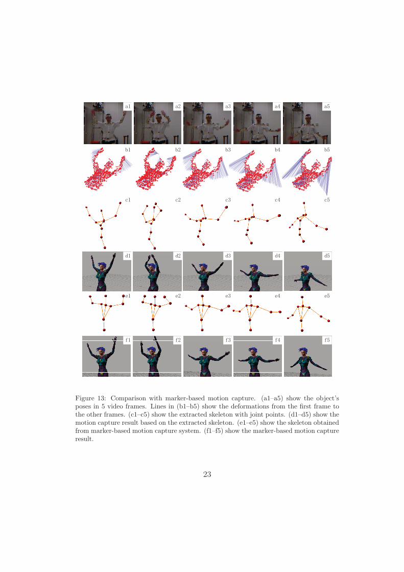
Figure 13: Comparison with marker-based motion capture. (a1–a5) show the object’sposes in 5 video frames. Lines in (b1–b5) show the deformations from the first frame tothe other frames. (c1–c5) show the extracted skeleton with joint points. (d1–d5) show themotion capture result based on the extracted skeleton. (e1–e5) show the skeleton obtainedfrom marker-based motion capture system. (f1–f5) show the marker-based motion captureresult.
23
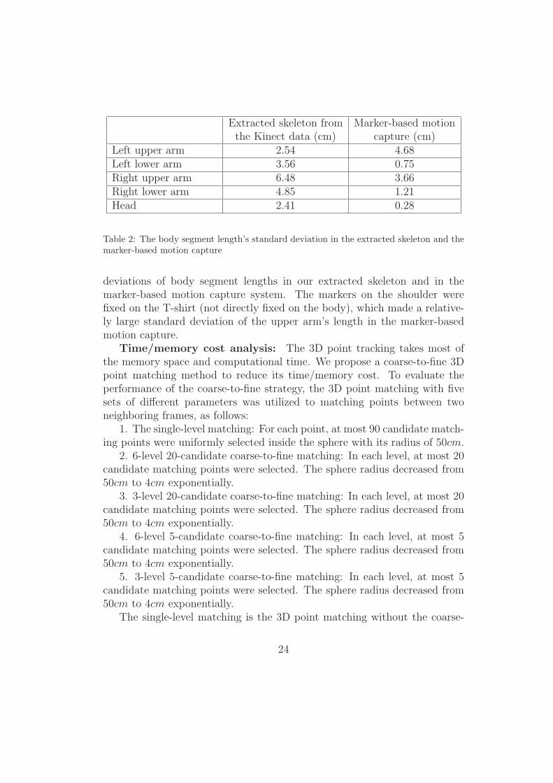
Extracted skeleton from Marker-based motionthe Kinect data (cm) capture (cm)
Left upper arm 2.54 4.68Left lower arm 3.56 0.75Right upper arm 6.48 3.66Right lower arm 4.85 1.21Head 2.41 0.28
Table 2: The body segment length’s standard deviation in the extracted skeleton and themarker-based motion capture
deviations of body segment lengths in our extracted skeleton and in themarker-based motion capture system. The markers on the shoulder werefixed on the T-shirt (not directly fixed on the body), which made a relative-ly large standard deviation of the upper arm’s length in the marker-basedmotion capture.
Time/memory cost analysis: The 3D point tracking takes most ofthe memory space and computational time. We propose a coarse-to-fine 3Dpoint matching method to reduce its time/memory cost. To evaluate theperformance of the coarse-to-fine strategy, the 3D point matching with fivesets of different parameters was utilized to matching points between twoneighboring frames, as follows:
1. The single-level matching: For each point, at most 90 candidate match-ing points were uniformly selected inside the sphere with its radius of 50cm.
2. 6-level 20-candidate coarse-to-fine matching: In each level, at most 20candidate matching points were selected. The sphere radius decreased from50cm to 4cm exponentially.
3. 3-level 20-candidate coarse-to-fine matching: In each level, at most 20candidate matching points were selected. The sphere radius decreased from50cm to 4cm exponentially.
4. 6-level 5-candidate coarse-to-fine matching: In each level, at most 5candidate matching points were selected. The sphere radius decreased from50cm to 4cm exponentially.
5. 3-level 5-candidate coarse-to-fine matching: In each level, at most 5candidate matching points were selected. The sphere radius decreased from50cm to 4cm exponentially.
The single-level matching is the 3D point matching without the coarse-
24
to-fine strategy, and the other four kinds of matching are the coarse-to-fine3D point matching. The candidate matching point number was set to 90 inthe single-level matching due to the memory limitation. Only 1/4 of the 3Dpoints in Sequence 5 (304 points per frame on average) were utilized in thefive kinds of 3D point matching to ensure that all the points inside the 50cmmatching sphere could be selected as the candidate matching points in thesingle-level matching.
We utilized MATLAB R2008a to realize our system. We tested the realtime/memory cost on a computer with Intel(R) Core(TM) i7 CPU M6402.80GHz. The coarse-to-fine point matching process took most of the com-putational time and memory in the whole skeleton extraction framework.
We utilized the coarse-to-fine strategy to reduce the large time/memorycost of the point matching process. In each level of the matching, let eachnode have at most k candidate matching points in total. The variable numberfor the energy minimization problem is |V |k, where |V | is the average node(point) number in the MRF. The matching time cost for each pair of framesis O(NL|E|k2), where N is the level number, L is the iteration numberof the TRW-S to minimize the total energy of the MRF, and |E| is theedge number in the MRF. The total time cost for the 3D point trackingis O(|F |(Ne + Nm)L|E|k2), where Ne is the level number in the estimationstep of the tracking, Nm is the level number in the modification step of thetracking, |F | is the total frame number. Note that we set a energy threshold(0.00001) for the MRF, and the growth of the variable number (k) increasedthe iteration number L for TRW-S to meet the energy threshold. We storedthe state transition matrices, so the memory cost for matching is O(|E|k2).
The real average time/memory cost for the 3D point matching with thefive sets of different parameters are shown in Table 3.
The matching performances with the five sets of different parameters asshown in Fig. 14. Some nodes (points in the MRF) in the single-level match-ing (k = 90, N = 1) were wrong matched. We set a large pairwise interactionpenalty τ to prevent two nodes from matching to the same candidate match-ing point (in Equation 3). Thus, if there were some many-to-one matchingconditions in some local areas, some nodes would be wrong matched. How-ever, in the coarse-to-fine 3D point matching (N > 1), the sphere for thecandidate-matching-point selection was large in low matching levels, andthere were a large number of points inside the sphere, so we avoided thewrong-matching problem by selecting different candidate-matching-point set-s from the sphere for different nodes. In high matching levels, this problem
25
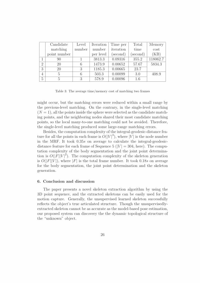
Candidate Level Iteration Time per Total Memorymatching number number iteration time cost
point number per level (second) (second) (KB)1 90 1 3813.3 0.09316 355.2 118062.72 20 6 1473.9 0.00652 57.67 5834.33 20 3 1185.3 0.00665 23.74 5 6 503.3 0.00099 3.0 408.95 5 3 578.9 0.00096 1.6
Table 3: The average time/memory cost of matching two frames
might occur, but the matching errors were reduced within a small range bythe previous-level matching. On the contrary, in the single-level matching(N = 1), all the points inside the sphere were selected as the candidate match-ing points, and the neighboring nodes shared their most candidate matchingpoints, so the local many-to-one matching could not be avoided. Therefore,the single-level matching produced some large-range matching errors.
Besides, the computation complexity of the integral-geodesic-distance fea-ture for all the points in each frame is O(|V |3), where |V | is the node numberin the MRF. It took 0.35s on average to calculate the integral-geodesic-distance feature for each frame of Sequence 5 (|V | = 304, here). The compu-tation complexity of the body segmentation and the joint point determina-tion is O(|F ||V |2). The computation complexity of the skeleton generationis O(|F ||V |), where |F | is the total frame number. It took 0.18s on averagefor the body segmentation, the joint point determination and the skeletongeneration.
6. Conclusion and discussion
The paper presents a novel skeleton extraction algorithm by using the3D point sequence, and the extracted skeletons can be easily used for themotion capture. Generally, the unsupervised learned skeleton successfullyreflects the object’s true articulated structure. Though the unsupervisedly-extracted skeleton cannot be as accurate as the model-based pose estimation,our proposed system can discovery the the dynamic topological structure ofthe “unknown” object.
26
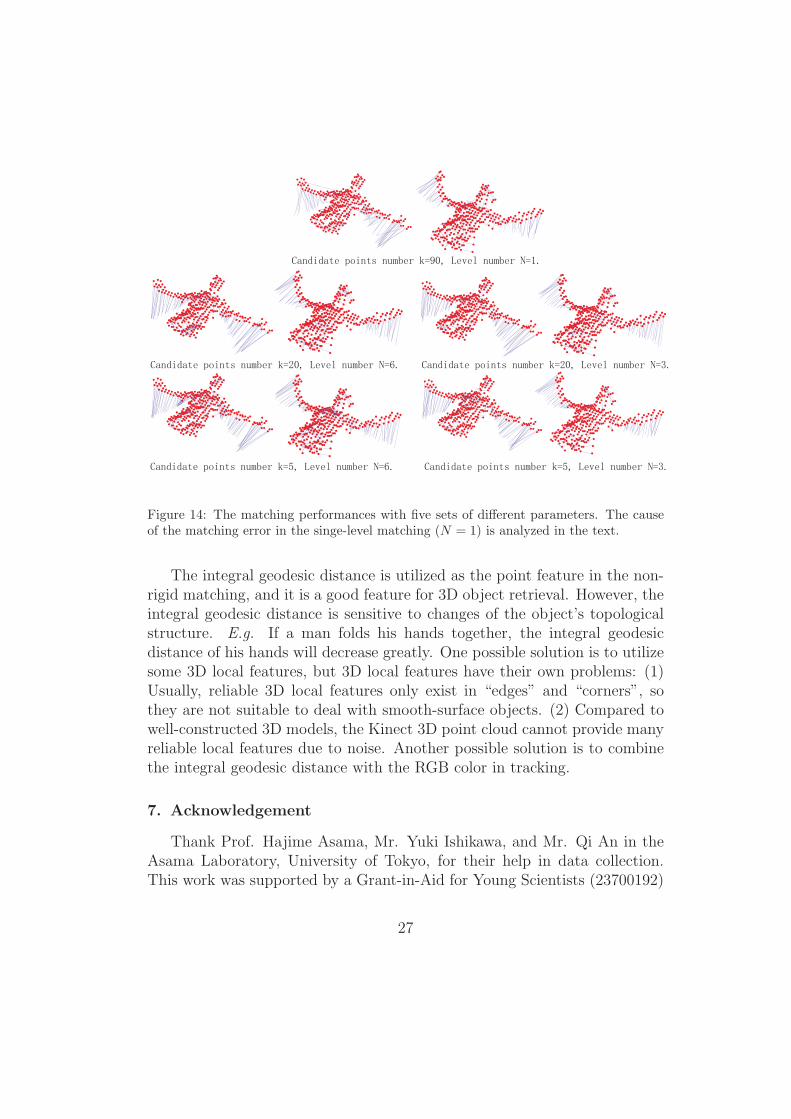
Figure 14: The matching performances with five sets of different parameters. The causeof the matching error in the singe-level matching (N = 1) is analyzed in the text.
The integral geodesic distance is utilized as the point feature in the non-rigid matching, and it is a good feature for 3D object retrieval. However, theintegral geodesic distance is sensitive to changes of the object’s topologicalstructure. E.g. If a man folds his hands together, the integral geodesicdistance of his hands will decrease greatly. One possible solution is to utilizesome 3D local features, but 3D local features have their own problems: (1)Usually, reliable 3D local features only exist in “edges” and “corners”, sothey are not suitable to deal with smooth-surface objects. (2) Compared towell-constructed 3D models, the Kinect 3D point cloud cannot provide manyreliable local features due to noise. Another possible solution is to combinethe integral geodesic distance with the RGB color in tracking.
7. Acknowledgement
Thank Prof. Hajime Asama, Mr. Yuki Ishikawa, and Mr. Qi An in theAsama Laboratory, University of Tokyo, for their help in data collection.This work was supported by a Grant-in-Aid for Young Scientists (23700192)
27

and Strategic Project to Support the Formation of Research Bases at Pri-vate Universities :Matching Fund Subsidy from MEXT (Ministry of Educa-tion,Culture,Sports,Science and Technology),2008-2012. This work was alsopartially funded by Microsoft Research.
References
[1] D. A. Ross, D. Tarlow, R. S. Zemel, Unsupervised learning of skeletonsfrom motion, In Europeon Conference on Computer Vision (2008) 560–573.
[2] D. A. Ross, D. Tarlow, R. S. Zemel, Learning articulated structure andmotion, In International Journal of Computer Vision 88 (2) (2010) 214–237.
[3] J. Yan, M. Pollefeys, A factorization-based approach for articulated non-rigid shape, motion and kinematic chain recovery from video, In IEEETransactions on Pattern Analysis and Machine Intelligence 30 (5) (2008)865–877.
[4] J. Yan, M. Pollefeys, Automatic kinematic chain building from featuretrajectories of articulated objects, In IEEE Computer Society Confer-ence on Computer Vision and Pattern Recognition 1 (2006) 712–719.
[5] P. Tresadern, I. Reid, Articulated structure from motion by factoriza-tion, In IEEE Computer Society Conference on Computer Vision andPattern Recognition 2 (2005) 1110–1115.
[6] D. Ramanan, D. Forsyth, K. Barnard, Building models of animals fromvideo, In IEEE Transactions on Pattern Analysis and Machine Intelli-gence 28 (8) (2006) 1319–1334.
[7] A. G. Kirk, J. F. O’Brien, D. A. Forsyth, Skeletal parameter estimationfrom optical motion capture data, In IEEE Computer Society Confer-ence on Computer Vision and Pattern Recognition 2 (2005) 782–788.
[8] J. Sturm, V. Pradeep, C. Stachniss, C. Plagemann, K. Konolige, W. Bur-gard, Learning kinematic models for articulated objects, In In Proc. ofthe International Conference on Artifical Intelligence (2009) 1851–1856.
28
[9] D. Attali, J.-O. Lachaud, Delaunay conforming iso-surface, skeleton ex-traction and noise removal, In Computational Geometry 19 (2001) 175–189.
[10] A. Tagliasacchi, H. Zhang, D. Cohen-Or, Curve skeleton extraction fromincomplete point cloud, In In Proceedings of ACM SIGGRAPH 28 (3)(2009) Article 71, 9 pages.
[11] O. K.-C. Au, C.-L. Tai, H.-K. Chu, D. Cohen-Or, T.-Y. Lee, Skeletonextraction by mesh contraction, In In Proceedings of ACM SIGGRAPH(2008) 1–44.
[12] G. Aujay, F. Hetroy, F. Lazarus, C. Depraz, Harmonic skeleton for realis-tic character animation, In ACM SIGGRAPH Symposium on ComputerAnimation (2007) 151–160.
[13] S. Schaefer, C. Yuksel, Example-based skeleton extraction, In Euro-graphics Symposium on Geometry Processing (2007) 153–162.
[14] Wikipedia. Kinect—Wikipedia, the free encyclopedia.http://en.wikipedia.org/wiki/Kinect, 2011. [Online; accessed 19–September–2011].
[15] J. Shi, C. Tomasi, Good features to track, In IEEE Computer SocietyConference on Computer Vision and Pattern Recognition (1994) 593–600.
[16] G. K. Cheung, S. Baker, T. Kanade, Shape-from-silhouette of articu-lated objects and its use for human body kinematics estimation andmotion capture, In IEEE Computer Society Conference on ComputerVision and Pattern Recognition 1 (2003) 77–83.
[17] C.-W. Chu, O. C. Jenkins, M. J. Mataric, Marker-less kinematic modeland motion capture from volume sequence, In IEEE Computer SocietyConference on Computer Vision and Pattern Recognition 2 (2003) 475–482.
[18] J. Sturm, V. Pradeep, C. Stachniss, Vision-based detection for learningarticulation models of cabinet doors and drawers in household environ-ment, In IEEE International Conference on Robotics and Automation(2010) 362–368.
29
[19] Y. Song, L. Goncalves, P. Perona, Unsupervised learning of human mo-tion, In IEEE Transactions on Pattern Analysis and Machine Intelli-gence 25 (7) (2003) 814–827.
[20] J. Shotton, A. Fitzgibbon, M. Cook, A. Blake, Real-time human poserecognition in parts from single depth images, In IEEE Computer SocietyConference on Computer Vision and Pattern Recognition (2011) 1297–1304.
[21] I. Oikonomidis, N. Kyriazis, A. A. Argyros, Efficient model-based 3dtracking of hand articulations using kinect, In British Machine VisionConference (2011) 1–11.
[22] A. Shekhovtsov, I. Kovtun, V. Hlavac, Efficient mrf deformation modelfor non-rigid image matching, In IEEE Computer Society Conference onComputer Vision and Pattern Recognition (2007) 1–6.
[23] A. Shekhovtsov, I. Kovtun, V. Hlavac, Efficient mrf deformation modelfor non-rigid image matching, In Computer Vision and Image Under-standing 112 (2008) 91–99.
[24] L. Torresani, V. Kolmogorov, C. Rother, Feature correspondence viagraph matching: Models and global optimization, In Europeon Confer-ence on Computer Vision (2) (2008) 596–609.
[25] V. Kolmogorov, Convergent tree-reweighted message passing for energyminimization, In IEEE Transactions on Pattern Analysis and MachineIntelligence 28 (10) (2006) 1568–1583.
[26] K. J. Lee, D. Kwon, I. D. Yun, S. U. Lee, Deformable 3d volume reg-istration using efficient mrfs model with decomposed nodes, In BritishMachine Vision Conference (2008) 1–10.
[27] A. Y. Ng, M. I. Jordan, Y. Weiss, On spectral clustering: Analysis andan algorithm, In Advances in Neural Information Processing Systems 14(NIPS) (2002) 849–856, Cambridge, MA,.
30


![Linear Span Network for Object Skeleton Detection · Early skeleton extraction methods treat skeleton detection as morphological op-erations [12,25,14,9,7,23,11]. One hypothesis is](https://img.pdfslide.net/doc/110x75/60704a391274e47e280e1ae3/linear-span-network-for-object-skeleton-detection-early-skeleton-extraction-methods.jpg)