Embed Size (px)
Citation preview
117
Imaging of Liquid Distribution withinCorrugated Sheet Structured PackingBeds by X-Ray Computed Tomography
P . M A R C H O T , D . T O Y E , M . C R I N E , G . L ` H O M M E ,
A . - M . P E L S S E R
Laboratoires de Ge nie Chimique, B6, Universite de LieÁ ge,Sart Tilman, B-4000 LieÁ ge;
Z . O L U J I C
Laboratory of Process Equipment, Delft University of Technology,NL-2628 CA Delft.
Although corrugated sheet structured packings are widely used indistillation and related operations, the understanding of their per-formance is still inadequate. Consequently this represents a signi-ficant barrier to further improvements. An obvious obstacle for thedevelopment of more detailed, discrete cell type predictive models,is an inadequate knowledge of the sources, nature and extent ofsmall scale liquid maldistribution. This obstacle could be over-come if we could see inside the packed bed during operation, i.e.develop a means to adequately image the liquid flow in a packedbed. Since X-ray computed tomography is a non-intrusive tech-nique with a spatial resolution high enough to unravel complexflow textures, it offers the potential to visualise the liquid flow pat-tern in a packed bed.
The X-ray tomograph employed in this study rotatesaround a vertical axis and scans horizontal sections of a 2 mlong column (made of polyethylene) with an internal diameter of0.6 m. In this study we evaluated the hydraulic performance of Mel-lapak 250 Y, which is made of polypropylene. The total height of thebed was 1.24 m. Four layers of packing were installed, each con-sisting of two semicircular segments. The experiments were per-formed with the air-water system at ambient conditions. A distri-butor placed above the bed provided liquid with an equivalent of106 drip points/m2. Some runs were performed using a point sour-ce distributor, bringing water directly from the supply tube onto thecentre point of the top packing element. A blower delivered air tothe bottom of the column. A detailed description of the tomograph
and the experimental procedure can be found elsewhere (Marchotet al, Trans IChemE 1999, Vol 77, Part A, 511).
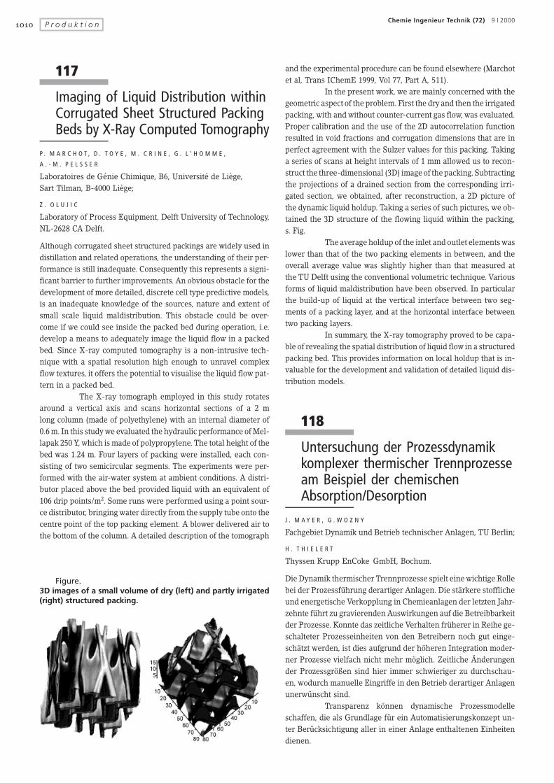
In the present work, we are mainly concerned with thegeometric aspect of the problem. First the dry and then the irrigatedpacking, with and without counter-current gas flow, was evaluated.Proper calibration and the use of the 2D autocorrelation functionresulted in void fractions and corrugation dimensions that are inperfect agreement with the Sulzer values for this packing. Takinga series of scans at height intervals of 1 mm allowed us to recon-struct the three-dimensional (3D) image of the packing. Subtractingthe projections of a drained section from the corresponding irri-gated section, we obtained, after reconstruction, a 2D picture ofthe dynamic liquid holdup. Taking a series of such pictures, we ob-tained the 3D structure of the flowing liquid within the packing,s. Fig.
The average holdup of the inlet and outlet elements waslower than that of the two packing elements in between, and theoverall average value was slightly higher than that measured atthe TU Delft using the conventional volumetric technique. Variousforms of liquid maldistribution have been observed. In particularthe build-up of liquid at the vertical interface between two seg-ments of a packing layer, and at the horizontal interface betweentwo packing layers.
In summary, the X-ray tomography proved to be capa-ble of revealing the spatial distribution of liquid flow in a structuredpacking bed. This provides information on local holdup that is in-valuable for the development and validation of detailed liquid dis-tribution models.
118
Untersuchung der Prozessdynamikkomplexer thermischer Trennprozesseam Beispiel der chemischenAbsorption/Desorption
J . M A Y E R , G . W O Z N Y
Fachgebiet Dynamik und Betrieb technischer Anlagen, TU Berlin;
H . T H I E L E R T
Thyssen Krupp EnCoke GmbH, Bochum.
Die Dynamik thermischer Trennprozesse spielt eine wichtige Rollebei der ProzessfuÈ hrung derartiger Anlagen. Die staÈ rkere stofflicheund energetische Verkopplung in Chemieanlagen der letzten Jahr-zehnte fuÈ hrt zu gravierenden Auswirkungen auf die Betreibbarkeitder Prozesse. Konnte das zeitliche Verhalten fruÈ herer in Reihe ge-schalteter Prozesseinheiten von den Betreibern noch gut einge-schaÈ tzt werden, ist dies aufgrund der hoÈheren Integration moder-ner Prozesse vielfach nicht mehr moÈ glich. Zeitliche Ønderungender ProzessgroÈ ûen sind hier immer schwieriger zu durchschau-en, wodurch manuelle Eingriffe in den Betrieb derartiger AnlagenunerwuÈ nscht sind.
Transparenz koÈ nnen dynamische Prozessmodelleschaffen, die als Grundlage fuÈ r ein Automatisierungskonzept un-ter BeruÈ cksichtigung aller in einer Anlage enthaltenen Einheitendienen.
Figure.3D images of a small volume of dry (left) and partly irrigated(right) structured packing.
1010 P r o d u k t i o nChemie Ingenieur Technik (72) 9 I 2000
Gegenstand des Forschungsprojektes war die experi-mentelle und theoretische Untersuchung des Koksofengasreini-gungsprozesses als Beispiel fuÈ r ein komplexes thermisches Trenn-verfahren. Innerhalb der sog. Ammoniak-Schwefelwasserstoff-KreislaufwaÈsche (AS-WaÈ sche) werden jeweils zwei Absorberund zwei Desorptionseinheiten eingesetzt. Diese Trennkolonnensind mit RecyclestroÈ men untereinander verbunden und somit so-wohl stofflich als auch uÈ ber eine WaÈ rmeintegration energetischgekoppelt. Die Gasreinigung wird mit einer chemischen Absorpti-on erreicht, deren Ziel es ist, die sauren Schadgase H2S und HCNaus dem Gasstrom mit einer waÈ sserigen AmmoniakloÈ sung zu ent-fernen. Die Regeneration des Absorbens geschieht im Desorpti-onsteil der Anlage.
Problematisch ist fuÈ r den Betrieb der Anlagen die Tat-sache, dass die eigentlichen ZielgroÈ ûen des Prozesses (Gasreinheitund Ammoniakbeladung im Abwasser) on line nicht ohne Weitereserfasst werden koÈ nnen. Die Betreiber fahren den Prozess haupt-saÈ chlich aufgrund von Erfahrungswerten und stellen sich auf un-terschiedliche Belastungen und Beladungen im Rohgas lediglichaufgrund von einigen uÈ ber den Tag verteilten Laboranalysen ein.
In Kooperation zwischen der TU Berlin und der FirmaThyssen Krupp EnCoke als Erbauer fuÈ r AS-WaÈ sche Anlagen wurdedieser Prozess sowohl stationaÈ r als auch dynamisch beschriebenund experimentell untersucht. Die stationaÈ ren Experimente wur-den auf dem GelaÈnde der Kokerei Thyssen Krupp Stahl (TKS) inDuisburg durchgefuÈ hrt. HierfuÈ r wurde eine an der TU-Berlin ge-fertigte Versuchsanlage (Trennkolonne DN 100, Sulzer Mellapak
350Y und Optiflow) im Bypass zu den technischen Ko-lonnen (Absorber und Desorber) betrieben.
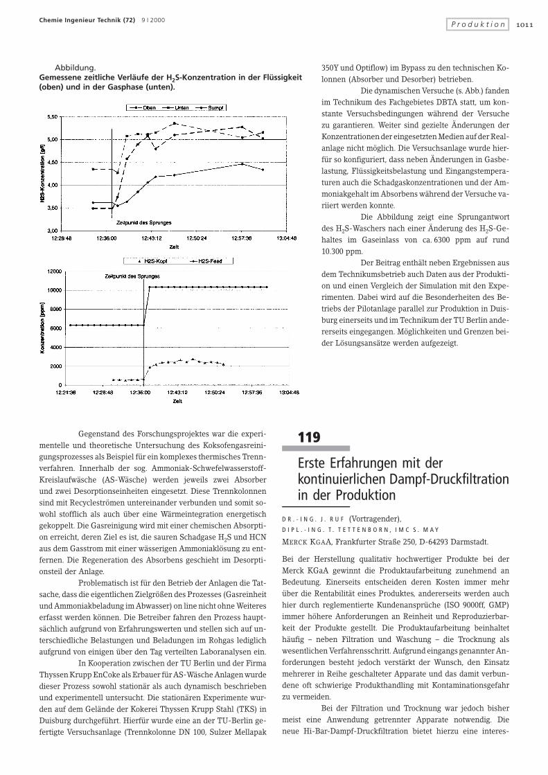
Die dynamischen Versuche (s. Abb.) fandenim Technikum des Fachgebietes DBTA statt, um kon-stante Versuchsbedingungen waÈhrend der Versuchezu garantieren. Weiter sind gezielte Ønderungen derKonzentrationen der eingesetzten Medien auf der Real-anlage nicht moÈ glich. Die Versuchsanlage wurde hier-fuÈ r so konfiguriert, dass neben Ønderungen in Gasbe-lastung, FluÈ ssigkeitsbelastung und Eingangstempera-turen auch die Schadgaskonzentrationen und der Am-moniakgehalt im Absorbens waÈ hrend der Versuche va-riiert werden konnte.
Die Abbildung zeigt eine Sprungantwortdes H2S-Waschers nach einer Ønderung des H2S-Ge-haltes im Gaseinlass von ca. 6300 ppm auf rund10.300 ppm.
Der Beitrag enthaÈ lt neben Ergebnissen ausdem Technikumsbetrieb auch Daten aus der Produkti-on und einen Vergleich der Simulation mit den Expe-rimenten. Dabei wird auf die Besonderheiten des Be-triebs der Pilotanlage parallel zur Produktion in Duis-burg einerseits und im Technikum der TU Berlin ande-rerseits eingegangen. MoÈ glichkeiten und Grenzen bei-der LoÈ sungsansaÈ tze werden aufgezeigt.
Abbildung.Gemessene zeitliche VerlaÈ ufe der H2S-Konzentration in der FluÈ ssigkeit(oben) und in der Gasphase (unten).
119
Erste Erfahrungen mit derkontinuierlichen Dampf-Druckfiltrationin der Produktion
D R . - I N G . J . R U F (Vortragender),
D I P L . - I N G . T . T E T T E N B O R N , I M C S . M A Y
MERCK KGAA, Frankfurter Straûe 250, D-64293 Darmstadt.
Bei der Herstellung qualitativ hochwertiger Produkte bei derMerck KGaA gewinnt die Produktaufarbeitung zunehmend anBedeutung. Einerseits entscheiden deren Kosten immer mehruÈ ber die RentabilitaÈ t eines Produktes, andererseits werden auchhier durch reglementierte KundenanspruÈ che (ISO 9000ff, GMP)immer hoÈ here Anforderungen an Reinheit und Reproduzierbar-keit der Produkte gestellt. Die Produktaufarbeitung beinhaltethaÈ ufig ± neben Filtration und Waschung ± die Trocknung alswesentlichen Verfahrensschritt. Aufgrund eingangs genannter An-forderungen besteht jedoch verstaÈ rkt der Wunsch, den Einsatzmehrerer in Reihe geschalteter Apparate und das damit verbun-dene oft schwierige Produkthandling mit Kontaminationsgefahrzu vermeiden.
Bei der Filtration und Trocknung war jedoch bishermeist eine Anwendung getrennter Apparate notwendig. Dieneue Hi-Bar-Dampf-Druckfiltration bietet hierzu eine interes-
1011P r o d u k t i o nChemie Ingenieur Technik (72) 9 I 2000


![Management thermischer Verletzungen im Kindesalter · gendlichen >5 Jahre für Jungen eher abzunehmen [1]. Management thermischer Verletzungen im Kindesalter Ingo Königs, Miriam](https://img.pdfslide.net/doc/110x75/5f5a206a05bac7660356853f/management-thermischer-verletzungen-im-kindesalter-gendlichen-5-jahre-fr-jungen.jpg)