Embed Size (px)
Citation preview
1
P/N AYRL-220-INST-FUL Rev D
Set screwsx2
Hex keyx1
M4 x 25.4mmpan head machine
screws
x2 #7 wood & #8-32machine x 20mm
Combination screws
x4
M4 x 8mmpan head machine
screws
x4
FAILURE TO FOLLOW THESE INSTRUCTIONS COULD RESULT IN DAMAGETO THE PRODUCT AND VOID THE FACTORY WARRANTY
Yale Real Living™ Touchscreen LeverInstallation and Programming Instructions
2
P/N AYRL-220-INST-FUL Rev D
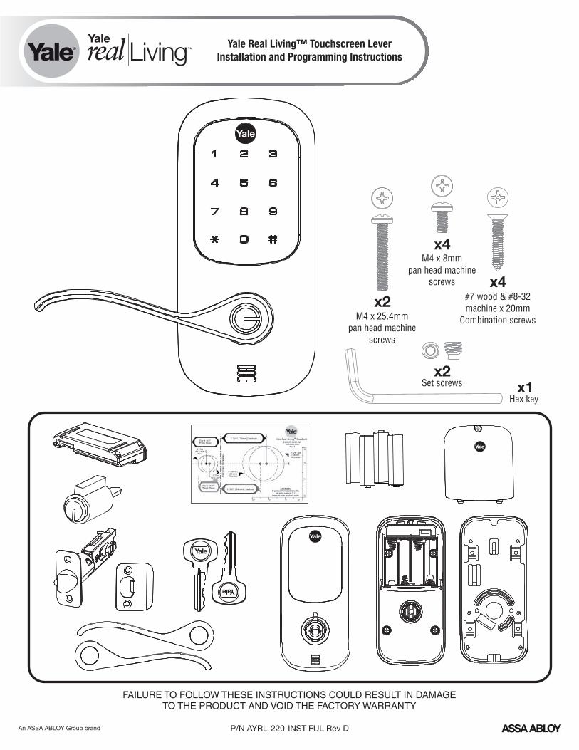
#2 Phillips Screwdriver
2-3/8" through bolt posts
2-3/4" through bolt postsNote: Adjustment based on backset
Ooptional
default
Preparing to Install
3
P/N AYRL-220-INST-FUL Rev D
?
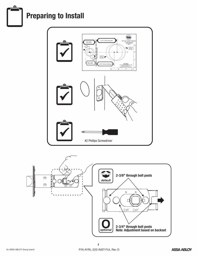
Left HandHinges Left.
Open Inward.“LH”
Left Hand Reverse Hinges Left.
Open Outward“LHR”
The hand of a door is determined from the secure side of the door. The term "secure" means the side from which you initially unlock and enter.
Determining Lever HandingLeft Hand Options
4
P/N AYRL-220-INST-FUL Rev D
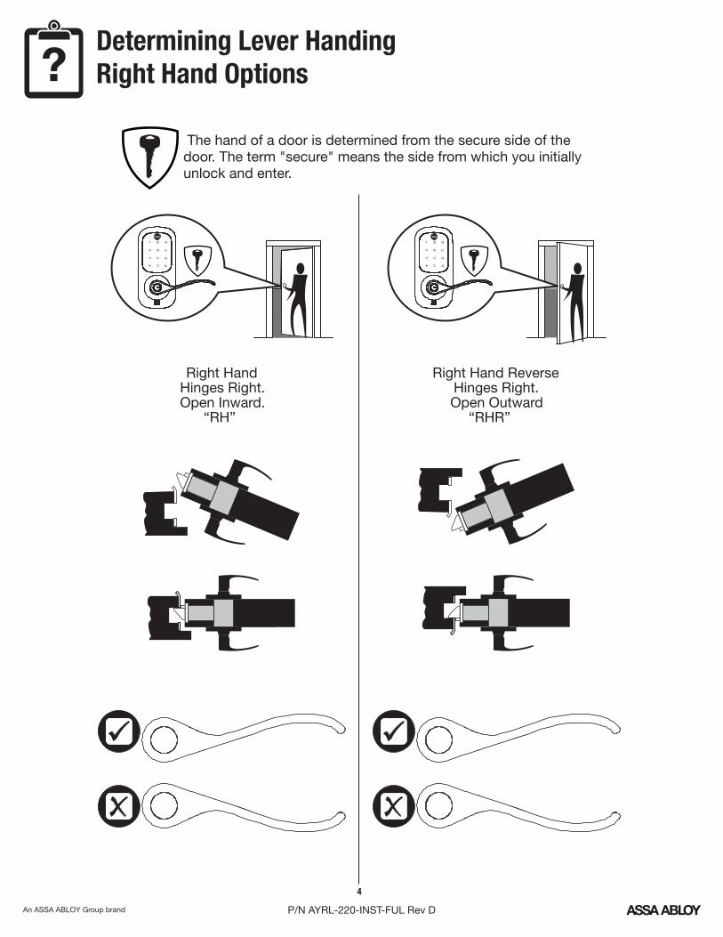
? The hand of a door is determined from the secure side of the door. The term "secure" means the side from which you initially unlock and enter.
Right HandHinges Right.Open Inward.
“RH”
Right Hand Reverse Hinges Right.Open Outward
“RHR”
Determining Lever HandingRight Hand Options
5
P/N AYRL-220-INST-FUL Rev D
x4
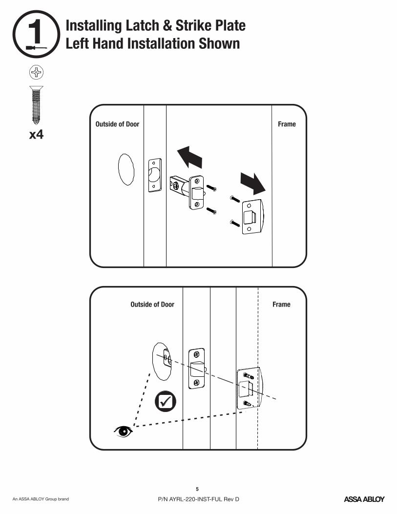
1 Installing Latch & Strike PlateLeft Hand Installation Shown
Outside of Door
Outside of Door
Frame
Frame
6
P/N AYRL-220-INST-FUL Rev D
2
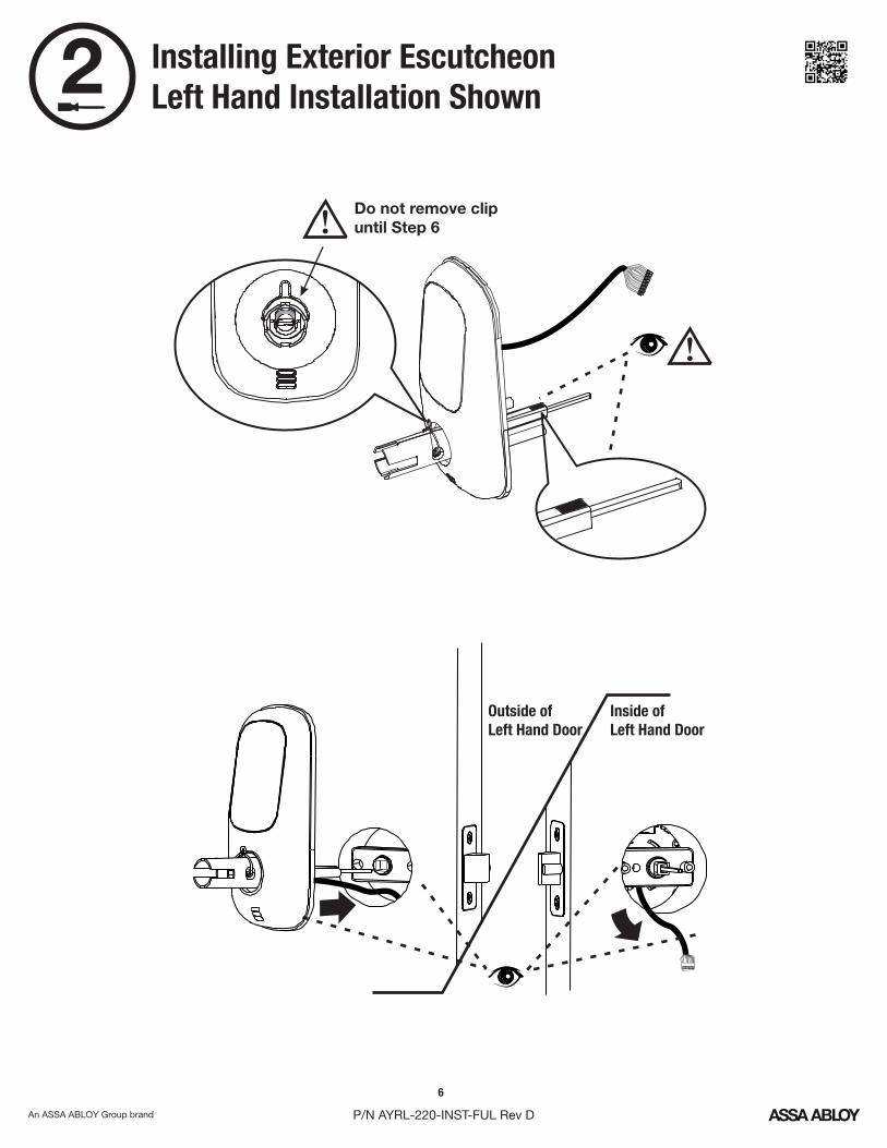
Inside of Left Hand Door
Outside of Left Hand Door
!Do not remove clipuntil Step 6
!
Installing Exterior Escutcheon Left Hand Installation Shown
7
P/N AYRL-220-INST-FUL Rev D
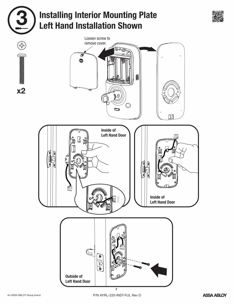
x2
3
Inside of Left Hand Door
Outside of Left Hand Door
Inside of Left Hand Door
Loosen screw toremove cover.
Installing Interior Mounting Plate Left Hand Installation Shown
4
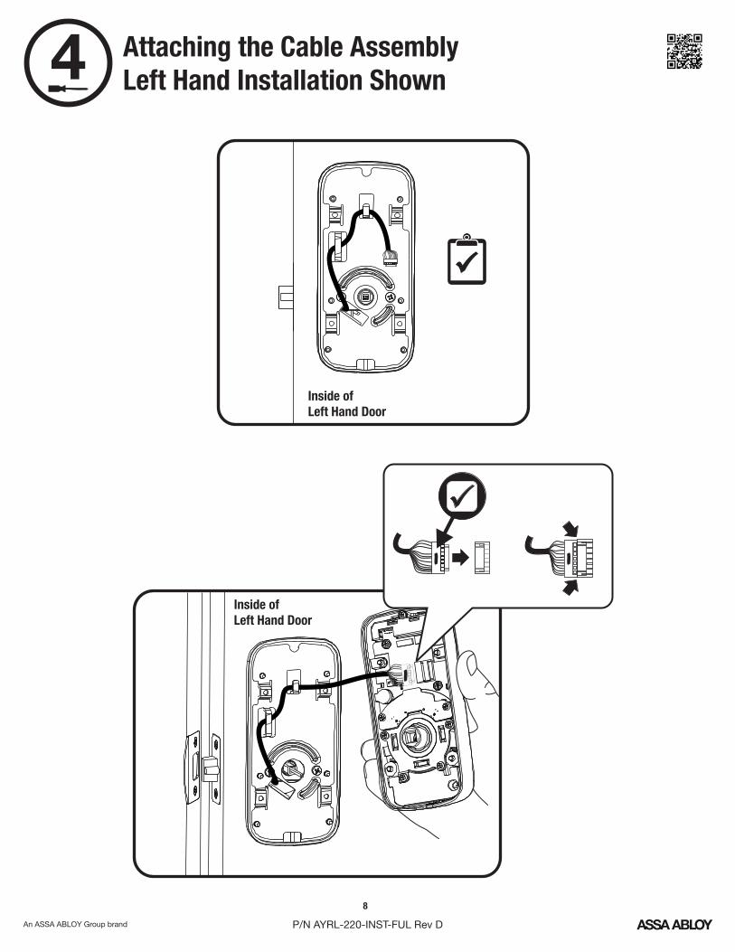
Inside of Left Hand Door
Inside of Left Hand Door
Attaching the Cable AssemblyLeft Hand Installation Shown
8
P/N AYRL-220-INST-FUL Rev D
9
P/N AYRL-220-INST-FUL Rev D
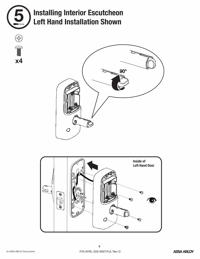
x4
5
Inside of Left Hand Door
Installing Interior EscutcheonLeft Hand Installation Shown
10
P/N AYRL-220-INST-FUL Rev D
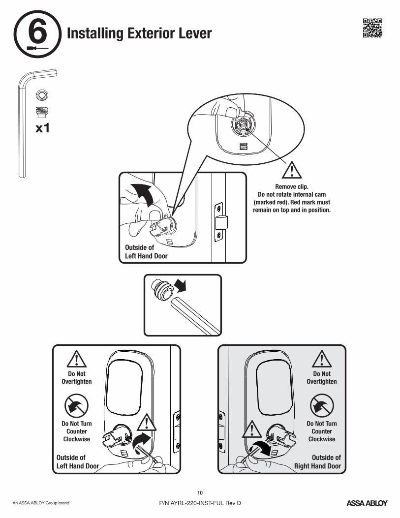
x1
6 Installing Exterior Lever
Remove clip.Do not rotate internal cam
(marked red). Red mark must remain on top and in position.
Outside of Left Hand Door
Outside of Left Hand Door
Do Not Overtighten
Do Not Turn Counter
Clockwise
!
!
!
!
!
Do Not Overtighten
Do Not Turn Counter
Clockwise
Outside of Right Hand Door
11
P/N AYRL-220-INST-FUL Rev D
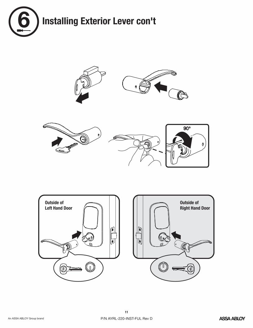
6 Installing Exterior Lever con't
Outside of Left Hand Door
Outside of Right Hand Door
12
P/N AYRL-220-INST-FUL Rev D
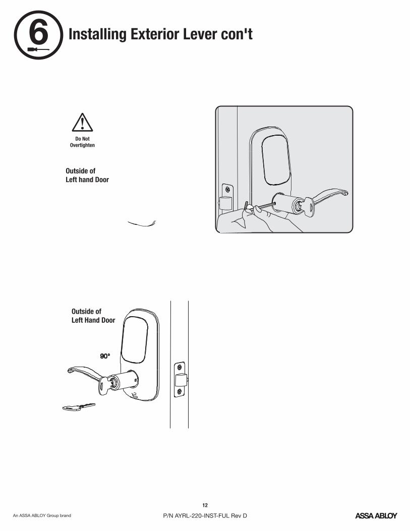
6 Installing Exterior Lever con't
Outside of Left hand Door
Outside of Left Hand Door
Do Not Overtighten
! !
Outside of Right Hand Door
Do Not Overtighten
Outside of Right Hand Door
13
P/N AYRL-220-INST-FUL Rev D
7
67
6
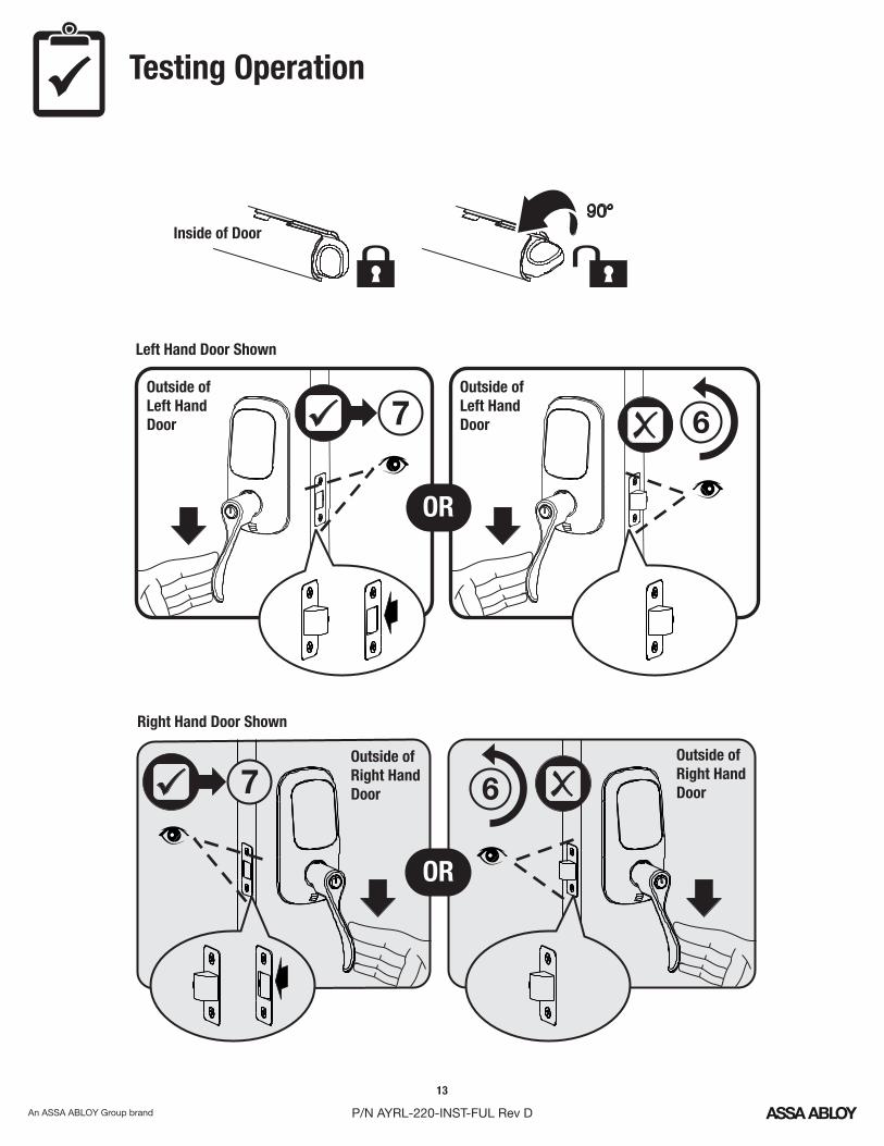
Testing Operation
Inside of Door
Outside of Left HandDoor
Outside of Right HandDoor
Outside of Left HandDoor
Outside of Right HandDoor
Left Hand Door Shown
Right Hand Door Shown
OR
OR
14
P/N AYRL-220-INST-FUL Rev D
7
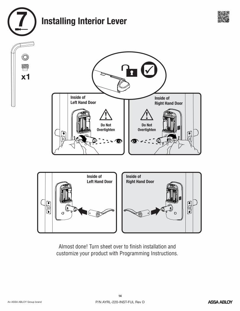
Inside of Left Hand Door
Inside of Right Hand Door
Do Not Overtighten
!Do Not
Overtighten
!
Inside of Left Hand Door
Inside of Right Hand Door
Almost done! Turn sheet over to finish installation andcustomize your product with Programming Instructions.
Installing Interior Lever
x1
15
P/N AYRL-220-INST-FUL Rev D
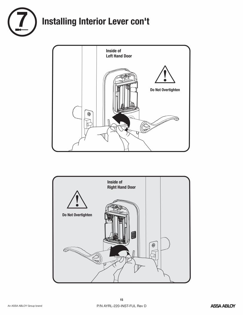
7 Installing Interior Lever con't
Inside of Left Hand Door
Inside of Right Hand Door
Do Not Overtighten
!
Do Not Overtighten
!
16
P/N AYRL-220-INST-FUL Rev D
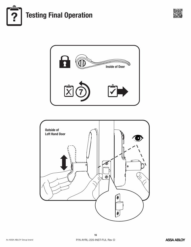
?
Inside of Door
7
Testing Final Operation
Outside of Left Hand Door
17
P/N AYRL-220-INST-FUL Rev D
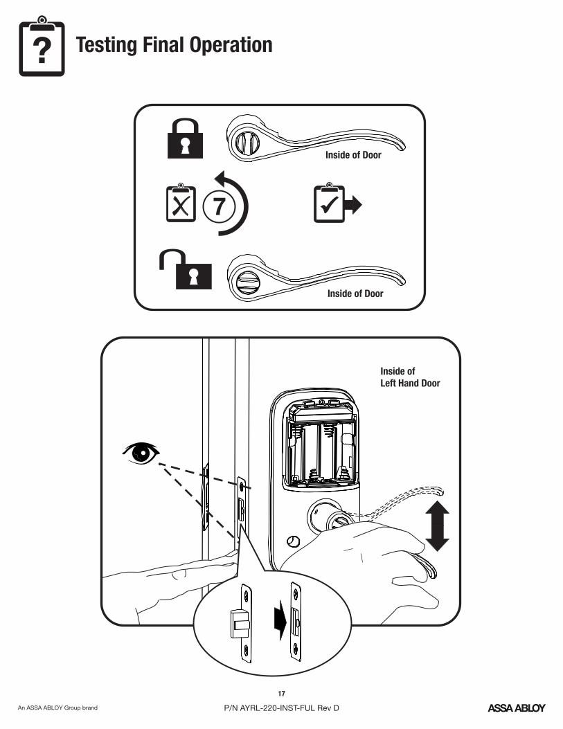
? Testing Final Operation
Inside of Left Hand Door
7
Inside of Door
Inside of Door
18
P/N AYRL-220-INST-FUL Rev D
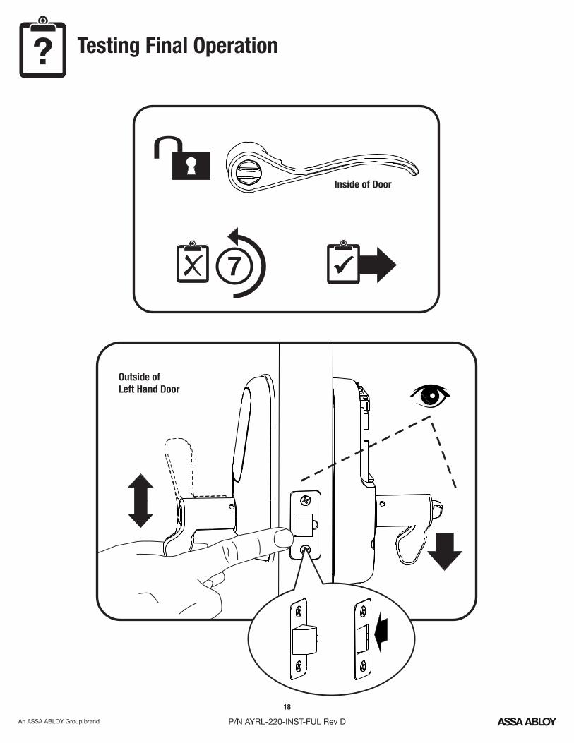
Inside of Door
7
? Testing Final Operation
Outside of Left Hand Door
19
P/N AYRL-220-INST-FUL Rev D
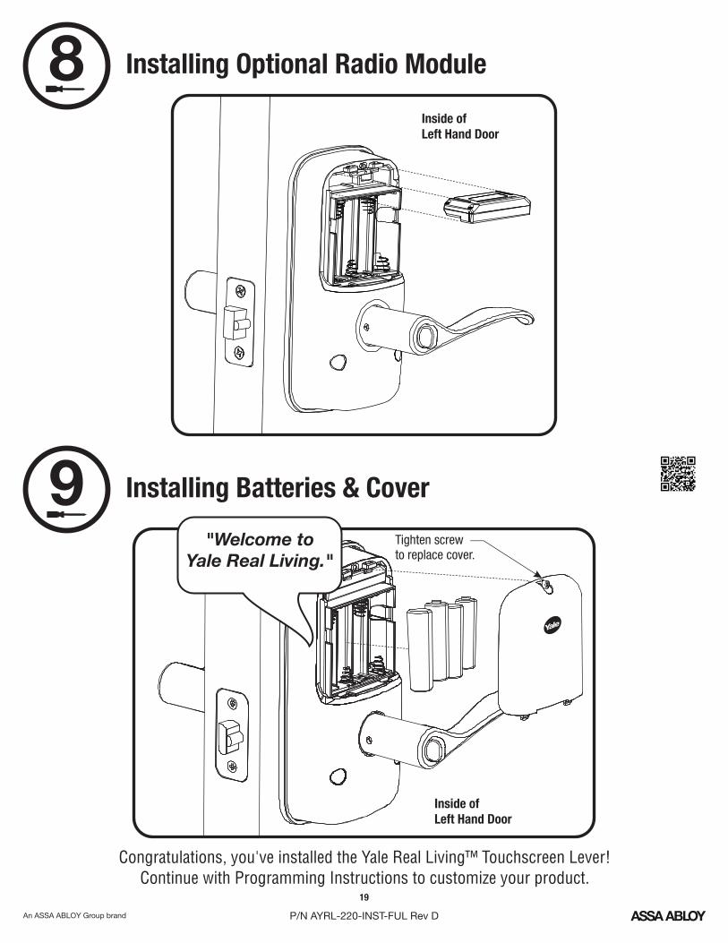
Installing Optional Radio Module8Inside of Left Hand Door
Installing Batteries & Cover9
Congratulations, you've installed the Yale Real Living™ Touchscreen Lever!Continue with Programming Instructions to customize your product.
Inside of Left Hand Door
"Welcome toYale Real Living."
Tighten screwto replace cover.
20
P/N AYRL-220-INST-FUL Rev D
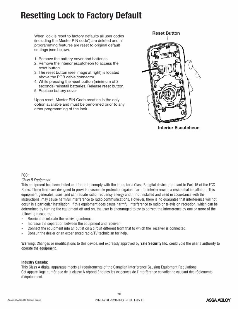
Resetting Lock to Factory Default
Reset Button
Interior Escutcheon
FCC:Class B Equipment This equipment has been tested and found to comply with the limits for a Class B digital device, pursuant to Part 15 of the FCC Rules. These limits are designed to provide reasonable protection against harmful interference in a residential installation. This equipment generates, uses, and can radiate radio frequency energy and, if not installed and used in accordance with the instructions, may cause harmful interference to radio communications. However, there is no guarantee that interference will not occur in a particular installation. If this equipment does cause harmful Interference to radio or television reception, which can be determined by turning the equipment off and on, the user is encouraged to try to correct the interference by one or more of the following measures: Reorient or relocate the receiving antenna. Increase the separation between the equipment and receiver. Connect the equipment into an outlet on a circuit different from that to which the receiver is connected. Consult the dealer or an experienced radio/TV technician for help.
Industry Canada:This Class A digital apparatus meets all requirements of the Canadian Interference Causing Equipment Regulations. Cet appareillage numérique de la classe A répond à toutes les exigences de l'interférence canadienne causant des règlements d'équipement.
Warning: Changes or modifications to this device, not expressly approved by Yale Security Inc. could void the user's authority to operate the equipment.
When lock is reset to factory defaults all user codes (including the Master PIN code*) are deleted and all programming features are reset to original default settings (see below).
1. Remove the battery cover and batteries.2. Remove the interior escutcheon to access the
reset button.3. The reset button (see image at right) is located
above the PCB cable connector.4. While pressing the reset button (minimum of 3
seconds) reinstall batteries. Release reset button.5. Replace battery cover.
Upon reset, Master PIN Code creation is the only option available and must be performed prior to any other programming of the lock.
21
P/N AYRL-220-INST-FUL Rev D
Changing Lock: Replacing Cylinder
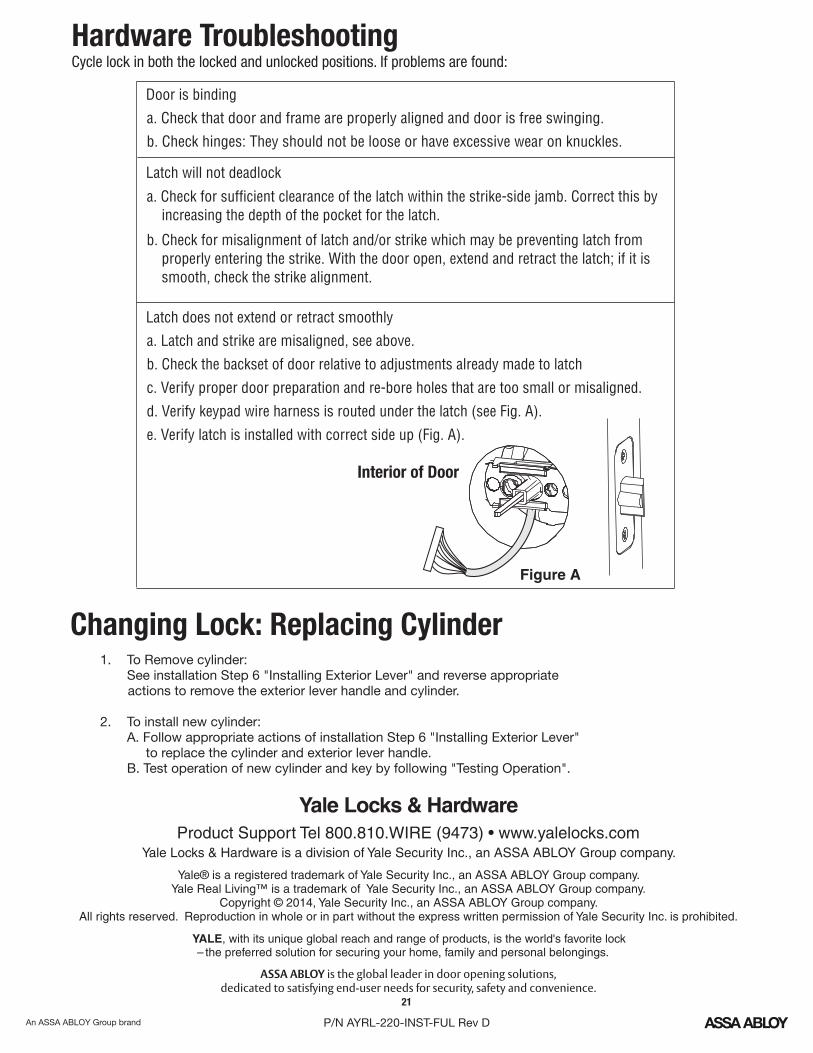
Hardware TroubleshootingCycle lock in both the locked and unlocked positions. If problems are found:
1. To Remove cylinder: See installation Step 6 "Installing Exterior Lever" and reverse appropriate
actions to remove the exterior lever handle and cylinder.
2. To install new cylinder: A. Follow appropriate actions of installation Step 6 "Installing Exterior Lever"
to replace the cylinder and exterior lever handle. B. Test operation of new cylinder and key by following "Testing Operation".
Yale® is a registered trademark of Yale Security Inc., an ASSA ABLOY Group company. Yale Real Living™ is a trademark of Yale Security Inc., an ASSA ABLOY Group company.
Copyright © 2014, Yale Security Inc., an ASSA ABLOY Group company. All rights reserved. Reproduction in whole or in part without the express written permission of Yale Security Inc. is prohibited.
ASSA ABLOY is the global leader in door opening solutions, dedicated to satisfying end-user needs for security, safety and convenience.
Product Support Tel 800.810.WIRE (9473) • www.yalelocks.comYale Locks & Hardware is a division of Yale Security Inc., an ASSA ABLOY Group company.
YALE, with its unique global reach and range of products, is the world's favorite lock– the preferred solution for securing your home, family and personal belongings.
Latch will not deadlock
a. Check for sufficient clearance of the latch within the strike-side jamb. Correct this by increasing the depth of the pocket for the latch.
b. Check for misalignment of latch and/or strike which may be preventing latch from properly entering the strike. With the door open, extend and retract the latch; if it is smooth, check the strike alignment.
Latch does not extend or retract smoothly
a. Latch and strike are misaligned, see above.
b. Check the backset of door relative to adjustments already made to latch
c. Verify proper door preparation and re-bore holes that are too small or misaligned.
d. Verify keypad wire harness is routed under the latch (see Fig. A).
e. Verify latch is installed with correct side up (Fig. A).
Door is binding
a. Check that door and frame are properly aligned and door is free swinging.
b. Check hinges: They should not be loose or have excessive wear on knuckles.
Interior of Door
Figure A
!
OR
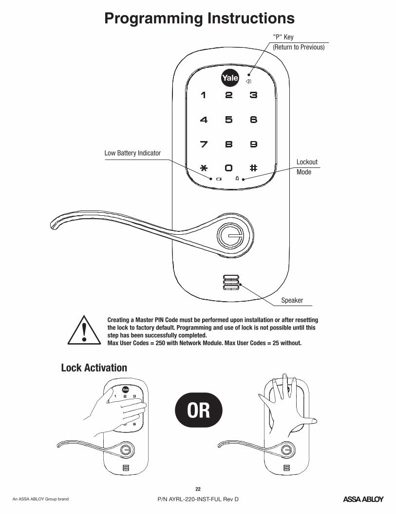
Creating a Master PIN Code must be performed upon installation or after resetting the lock to factory default. Programming and use of lock is not possible until this step has been successfully completed.Max User Codes = 250 with Network Module. Max User Codes = 25 without.
"P" Key(Return to Previous)
Low Battery IndicatorLockoutMode
Speaker
Lock Activation
Programming Instructions
22
P/N AYRL-220-INST-FUL Rev D
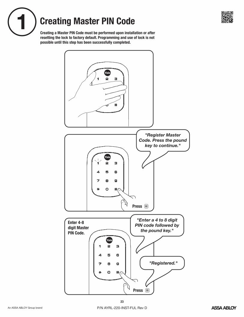
1 Creating Master PIN CodeCreating a Master PIN Code must be performed upon installation or after resetting the lock to factory default. Programming and use of lock is not possible until this step has been successfully completed.
Enter 4-8digit MasterPIN Code.
Press
Press
"Register MasterCode. Press the pound
key to continue."
"Enter a 4 to 8 digitPIN code followed by
the pound key."
"Registered."
23
P/N AYRL-220-INST-FUL Rev D
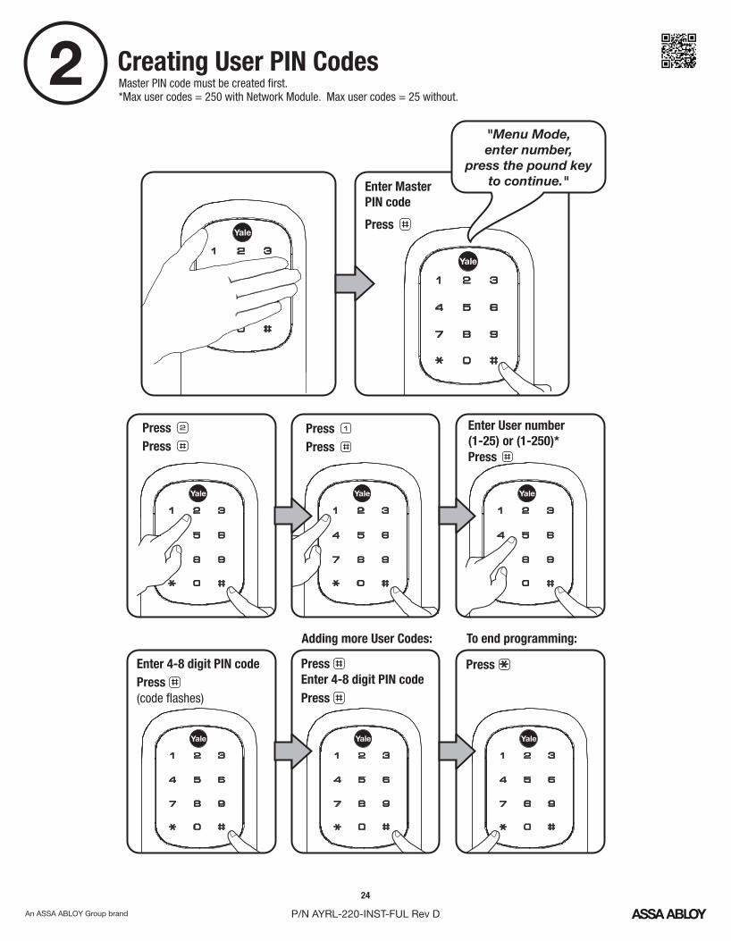
2 Creating User PIN CodesMaster PIN code must be created first.*Max user codes = 250 with Network Module. Max user codes = 25 without.
Enter MasterPIN code
Press Press
Press
Press Press
Press
Enter User number(1-25) or (1-250)*
Press
Adding more User Codes:
Enter 4-8 digit PIN code
Press
To end programming:
Enter 4-8 digit PIN codePress (code flashes)
Press
"Menu Mode, enter number,
press the pound key to continue."
24
P/N AYRL-220-INST-FUL Rev D
25
P/N AYRL-220-INST-FUL Rev D
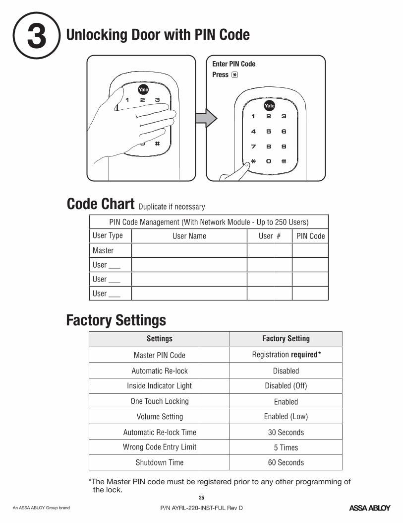
3 Unlocking Door with PIN Code
Enter PIN Code Press
Registration required*
Wrong Code Entry Limit 5 Times
One Touch Locking Enabled
Inside Indicator Light Disabled (Off)
Factory SettingsSettings Factory Setting
Master PIN Code
Automatic Re-lock Disabled
Volume Setting Enabled (Low)
Automatic Re-lock Time 30 Seconds
Shutdown Time 60 Seconds
*The Master PIN code must be registered prior to any other programming of the lock.
Code Chart Duplicate if necessary
PIN Code Management (With Network Module - Up to 250 Users)
Master
User ___
User ___
User ___
User NameUser Type PIN CodeUser #
26
P/N AYRL-220-INST-FUL Rev D
DefinitionsAll Code Lockout Mode: This feature is enabled by the Master code. When enabled, it restricts all user (except Master) PIN code access. When attempting to enter a code while the unit is in Lockout, the RED locked padlock will appear on the screen.
Automatic Re-lock Time: After a successful code entry and the unit unlocks, it will automatically re-lock after thirty (30) seconds.
Inside Indicator Light: Located on the interior escutcheon. Shows active status (Locked) of lock and can be enabled or disabled in the Advanced Lock Settings (Main Menu selection #3).
Language Setting Mode: Choosing English (1), Spanish (2) or French (3) becomes the (default) setting for the lock's voice prompts.
Low Battery: When battery power is low, the Low Battery Warning indicator flashes RED. If battery power is completely lost, use the cylinder key override.
Master PIN Code: The Master PIN code is used for programming and for feature settings. It must be created prior to programming the lock. The Master code will also operate (unlock/lock) the lock.
Network Module Setting: With the optional Network Module installed, this setting becomes available thru the Main Menu (7) and allows the lock to connect with a network controller.
One Touch Locking: When the latch is retracted, activating the keypad will extend the latch (during Automatic Re-lock duration or when Automatic Re-lock is disabled). When One-Touch Re-lock is not in use (disabled), any valid PIN code will re-lock the lock.
Previous: While in Menu Mode, pressing this icon cancels the current operation and returns the user to the previous step.
Shutdown Time: The unit will shutdown (flashing RED) for sixty (60) seconds and not allow operation after the wrong code entry limit (5 attempts) has been met.
Tamper Alert: Audible alarm sounds if attempting to forcibly remove outside lock from door.
User PIN Code: The User code operates the lock. Maximum number of user codes is 250 with Network Module; without Network Module, maximum is 25 users codes. Note: When deleting User PIN code(s), screen will display User Number (not PIN code) being deleted.
Volume Setting Mode: The volume setting for PIN code verification is set to Low (2) by default; otherwise it can be set to High (1) or Silent (3) for quiet areas.
Wrong Code Entry Limit: After five (5) unsuccessful attempts at entering a valid PIN code, the unit will shut down and not allow operation.
27
P/N AYRL-220-INST-FUL Rev D
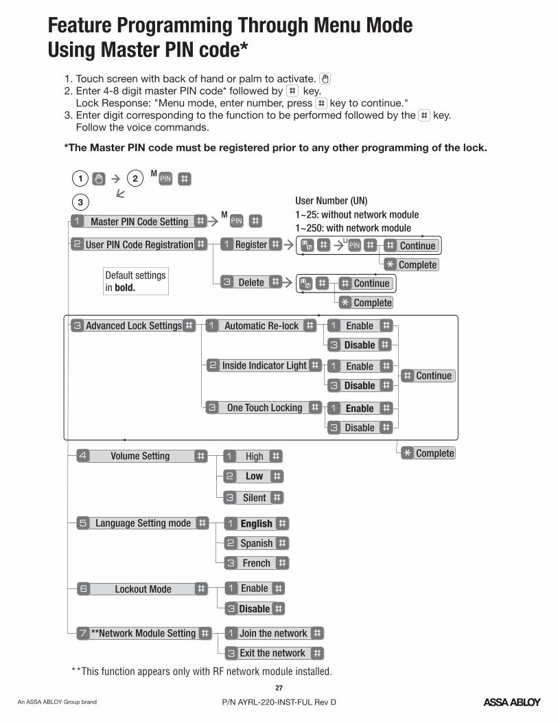
Feature Programming Through Menu ModeUsing Master PIN code*
Continue
Complete
Continue
Complete
1. Touch screen with back of hand or palm to activate.2. Enter 4-8 digit master PIN code* followed by key. Lock Response: "Menu mode, enter number, press key to continue."3. Enter digit corresponding to the function to be performed followed by the key. Follow the voice commands.
*The Master PIN code must be registered prior to any other programming of the lock.
Master PIN Code SettingM
User PIN Code Registration
Register
Delete
Advanced Lock Settings
Volume Setting
Language Setting mode
Lockout Mode
**Network Module Setting Join the network
Enable
Disable
Exit the network
User Number (UN)1~25: without network module1~250: with network module
U
**This function appears only with RF network module installed.
Automatic Re-lock Enable
Disable
Inside Indicator Light
One Touch Locking Enable
Disable
Enable
Disable
Default settingsin bold.
English
Spanish
French
3
M1 2
Silent
Low
High
Continue
Complete
28
P/N AYRL-220-INST-FUL Rev D
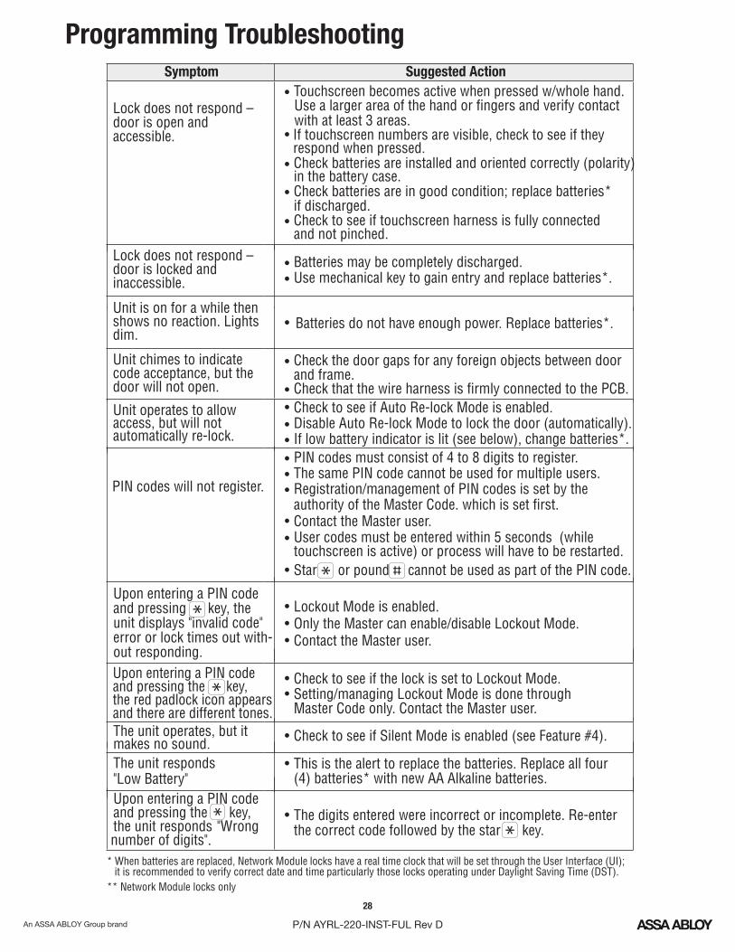
Programming Troubleshooting
Symptom Suggested Action
Lock does not respond – door is open and accessible.
• Touchscreen becomes active when pressed w/whole hand.
• Check batteries are installed and oriented correctly (polarity) in the battery case.
• Check batteries are in good condition; replace batteries* if discharged.
• Check to see if touchscreen harness is fully connected and not pinched.
• Batteries may be completely discharged.• Use mechanical key to gain entry and replace batteries*.
Unit chimes to indicate code acceptance, but thedoor will not open.
• Check the door gaps for any foreign objects between door and frame.
• Check that the wire harness is firmly connected to the PCB.Unit operates to allow access, but will notautomatically re-lock.
• Check to see if Auto Re-lock Mode is enabled.• Disable Auto Re-lock Mode to lock the door (automatically).• If low battery indicator is lit (see below), change batteries*.
PIN codes will not register.
• PIN codes must consist of 4 to 8 digits to register.• The same PIN code cannot be used for multiple users. • Registration/management of PIN codes is set by the
authority of the Master Code. which is set first.• Contact the Master user.• User codes must be entered within 5 seconds (while
touchscreen is active) or process will have to be restarted.• Star or pound cannot be used as part of the PIN code.
Upon entering a PIN code and pressing key, theunit displays "invalid code" error or lock times out with-out responding.
• Lockout Mode is enabled.• Only the Master can enable/disable Lockout Mode.• Contact the Master user.
Upon entering a PIN code and pressing the key, the red padlock icon appearsand there are different tones.
• Check to see if the lock is set to Lockout Mode.• Setting/managing Lockout Mode is done through
Master Code only. Contact the Master user.
The unit operates, but it makes no sound. • Check to see if Silent Mode is enabled (see Feature #4).
The unit responds "Low Battery"
• This is the alert to replace the batteries. Replace all four (4) batteries* with new AA Alkaline batteries.
Upon entering a PIN code and pressing the key, the unit responds "Wrongnumber of digits".
• The digits entered were incorrect or incomplete. Re-enter the correct code followed by the star key.
* When batteries are replaced, Network Module locks have a real time clock that will be set through the User Interface (UI); it is recommended to verify correct date and time particularly those locks operating under Daylight Saving Time (DST).
Lock does not respond – door is locked and inaccessible.
Use a larger area of the hand or fingers and verify contactwith at least 3 areas.If touchscreen numbers are visible, check to see if they respond when pressed.
Batteries do not have enough power. Replace batteries*.• Unit is on for a while thenshows no reaction. Lightsdim.
•
** Network Module locks only