Embed Size (px)
Citation preview
Instructions for Installation,Servicing and UseLEAVE THESE INSTRUCTIONSWITH THE END-USER
Unvented HotWater Storage
Cylinders
2
TABLE OF CONTENTS 1. GENERAL INFORMATION
1.1 DELIVERY
2. INSTALLATION
2.1 WATER REGULATIONS
2.2 BUILDING REGULATIONS
2.3 HOW THE APPLIANCE WORKS
2.4 OVERALL DIMENSIONS
2.5 COLD WATER SUPPLY
2.6 SITING AND FIXING
2.7 CONNECTION OF MAINS WATER SUPPLY
2.8 COLD WATER COMBINATION VALVE
2.9 CONNECTION TO SERVICES
2.10 SECONDARY RETURN
2.11 DISCHARGE PIPEWORK
2.12 ELECTRICAL DIAGRAMS
3. COMMISSIONING
4. MAINTENANCE
4.1 PROTECH ANTI-CORROSION SYSTEM
4.2 THERMAL CUT-OUT(S)4.3 IMMERSION HEATER(S)4.4 UNVENTED CONTROLS
4.5 THERMOSTATS
5. FAULT FINDING
6. TECHNICAL INFORMATION
This manual is an integral and essential part of the product. It should be keptwith the appliance so that it can be consulted by the user and our authorisedpersonnel.
Please read carefully the instructions and notices about the appliancecontained in this manual, as they provide important information regarding thesafe installation, use and maintenance of the cylinder.Failure to do so may invalidate the guarantee.
The range is available with the following options:
The Wall-hung range (50, 75, 100 litre models), which are supplied as thefollowing;
One box containing;1) The cylinder with factory fitted temperature & pressure relief valve,
immersion heater and thermostat with thermal cut-out.
One box containing;1) Unvented control pack (expansion vessel, 2 piece cold water combination
valve and tundish), instructions for installation, servicing and use and theBenchmark log book).
The Ariston Contract floor-standing range (125, 150, 200 and 300 litremodels).
The Contract is supplied with the following;
One box containing;1) The cylinder with factory fitted temperature & pressure relief valve.
One box containing;1) Unvented control pack (expansion vessel, 2 piece cold water combination
valve and tundish), motorised valve (indirect only). Immersion heater(s)and thermostat(s) with thermal cut-out(s), cylinder thermostat withthermal cut-out (indirect only), feet (x3), instructions for installation,servicing and use and the Benchmark log book.
The High Capacity floor-standing range (500 litre models), which aresupplied as the following;
One box containing;1) The cylinder with factory fitted temperature & pressure relief valve.
1) Unvented control pack (expansion vessel, 2 piece cold water combinationvalve and tundish), motorised valve (indirect only). Immersion heater(s)and thermostat(s) with thermal cut-out(s), cylinder thermostat withthermal cut-out (indirect only), feet (x 3), instructions for installation,servicing and use and the Benchmark log book.
1. GENERAL INFORMATION
3
1.2 DELIVERY
4
2.3 HOW THE APPLIANCE
WORKS
2. INSTALLATION
These regulations (byelaws in Scotland) ensure a good supply ofwholesome water, and that only approved materials, pipes and fittings areused to convey water.
These are a statutory document and take priority over all other regulationsand recommendations. The installation of an unvented hot water storagecylinder is classified as a “Controlled Service” and Regulation G3 applies. Tomeet the requirements of the Regulation, installation of an unvented systemshould be undertaken by a “competent installer”.All installations of unvented hot water storage systems having a capacity ofmore than 15 litres should be notified to the relevant Local Authority bymeans of building notice or by the submission of full plans. It is important tonote that it is a criminal offense to install an unvented hot water storagesystem without notifying the Local Authority. The installation of theunvented cylinder and hot water installation must comply with BS 6700 andthe HSE Legionella Code of Practice.
The immersion heater(s) are controlled through a thermostat which sensesthe water temperature. The operating temperature can be pre-set byadjusting the spindle in the head of the thermostat. In addition to thethermostat there is a thermal cut-out incorporated if the thermostat fails andthe water temperature rises too high. Once the cut-out operates it can onlybe re-set manually after the fault has been rectified.Indirect models have dual thermal controls. In addition to the above there isa separate cylinder thermostat and thermal cut-out for controlling the indirectcircuit. Again the thermal cut-out operates if the cylinder thermostat fails, bydisconnecting the live feed (call for hot water) from the programmer.
All High Capacity 500 litre models, Wall-hung units and the Contract andFloor-standing models utilise the ProTech anti-corrosion system (electronicanode).
The factory fitted temperature & pressure relief valve at the top of thecylinder is a safety device to back-up the thermostat(s) and thermal cut-out(s). It works by sensing an excess in water temperature or pressure andreleasing the hot water into a discharge tundish and drain.The cylinder will only work in the vertical position. The inlet pipe needs todeliver cold water to the bottom of the tank. When water is heated itexpands. To accommodate this increase in volume an expansion vessel isprovided. A cold water combination valve is also provided in two pieces,loose jointed for ease of installation. These comprise a combined linestrainer/pressure reducing valve and core non-return valve/expansion reliefvalve.The strainer prevents any debris entering the other controls. The pressurereducer ensures the correct operation of the expansion vessel, and preventsany damage to the control valves through too great a pressure.The non-return valve ensures the water expansion is forced into theexpansion vessel and prevents contamination of the mains cold watersupply. The expansion relief valve will discharge expanded water to thedischarge tundish if the expansion vessel fails.
2.1 WATER REGULATIONS
2.2 BUILDING REGULATIONS
5
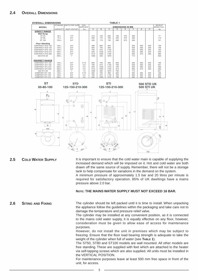
It is important to ensure that the cold water main is capable of supplying theincreased demand which will be imposed on it. Hot and cold water are bothdrawn off the same source of supply. Remember, there will not be a storagetank to help compensate for variations in the demand on the system.A minimum pressure of approximately 1.5 bar and 20 litres per minute isrequired for satisfactory operation. 85% of UK dwellings have a mainspressure above 2.0 bar.
NOTE: THE MAINS WATER SUPPLY MUST NOT EXCEED 16 BAR.
The cylinder should be left packed until it is time to install. When unpackingthe appliance follow the guidelines within the packaging and take care not todamage the temperature and pressure relief valve.The cylinder may be installed at any convenient position, as it is connectedto the mains cold water supply, it is equally effective on any floor, however,consideration must be given to allow ease of access for maintenancepurposes.However, do not install the unit in premises which may be subject tofreezing. Ensure that the floor load bearing strength is adequate to take theweight of the cylinder when full of water (see TABLE 1).The ST50, ST80 and ST100 models are wall mounted. All other models arefree standing. These are supplied with feet which are attached to the heatervia self-tapping screws which are also supplied. All units must be installed inthe VERTICAL POSITION.For maintenance purposes leave at least 500 mm free space in front of theunit, for access.
2.5 COLD WATER SUPPLY
2.4 OVERALL DIMENSIONS
2.6 SITING AND FIXING
SECONDARY RETURN
COMBINATION VALVE
EXPANSION RELIEF PIPE
COLD MAINS-IN
22mm
DRAIN
EXPANSION VESSEL
PRESSURE + TEMPERATURE RELIEF VALVE
HOT SUPPLY 22mm
TUNDISH
22mm
MAX. 100mm
6
FIG. 2.2
2.7 CONNECTION OF MAINS
WATER SUPPLY
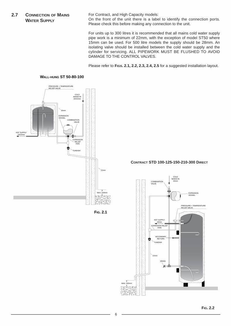
For Contract, and High Capacity models:On the front of the unit there is a label to identify the connection ports.Please check this before making any connection to the unit.
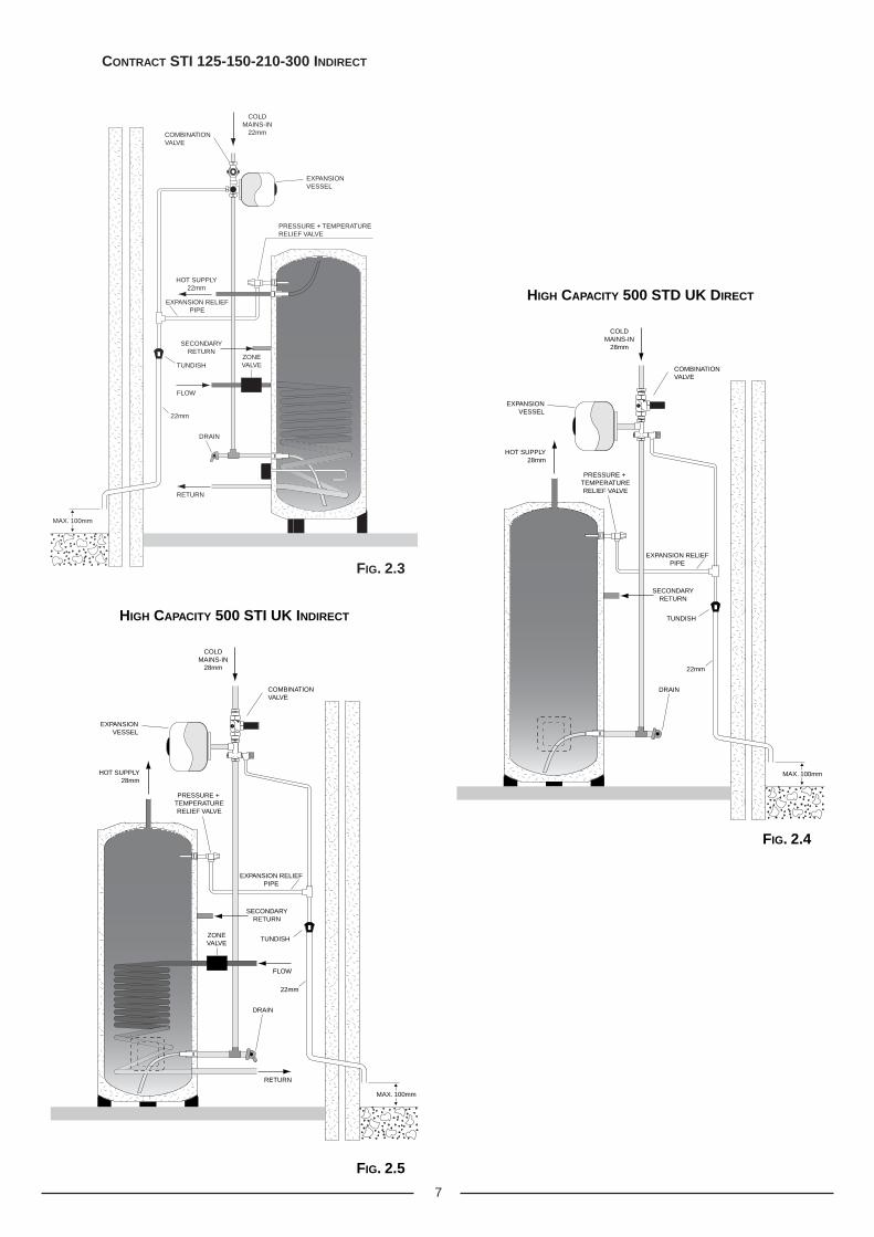
For units up to 300 litres it is recommended that all mains cold water supplypipe work is a minimum of 22mm, with the exception of model ST50 where15mm can be used. For 500 litre models the supply should be 28mm. Anisolating valve should be installed between the cold water supply and thecylinder for servicing. ALL PIPEWORK MUST BE FLUSHED TO AVOIDDAMAGE TO THE CONTROL VALVES.
Please refer to FIGS. 2.1, 2.2, 2.3, 2.4, 2.5 for a suggested installation layout.
CONTRACT STD 100-125-150-210-300 DIRECT
COMBINATION VALVE
EXPANSION RELIEF
PIPE
COLD MAINS-IN 15/22mm
EXPANSION VESSEL
PRESSURE + TEMPERATURE RELIEF VALVE
HOT SUPPLY 15/22mm
TUNDISH
15mm
22mm
MAX. 100mm
FIG. 2.1
WALL-HUNG ST 50-80-100
7
RETURN
FLOW
SECONDARYRETURN
COMBINATIONVALVE
EXPANSION RELIEFPIPE
COLDMAINS-IN
22mm
DRAIN
EXPANSIONVESSEL
PRESSURE + TEMPERATURERELIEF VALVE
ZONEVALVE
HOT SUPPLY22mm
TUNDISH
22mm
MAX. 100mm
FIG. 2.3
CONTRACT STI 125-150-210-300 INDIRECT
SECONDARY RETURN
COMBINATION VALVE
EXPANSION RELIEF PIPE
COLD MAINS-IN
28mm
DRAIN
EXPANSION VESSEL
PRESSURE + TEMPERATURE RELIEF VALVE
HOT SUPPLY 28mm
TUNDISH
22mm
MAX. 100mm
FIG. 2.4
HIGH CAPACITY 500 STD UK DIRECT
RETURN
FLOW
SECONDARY RETURN
COMBINATION VALVE
EXPANSION RELIEF PIPE
COLD MAINS-IN
28mm
DRAIN
EXPANSION VESSEL
PRESSURE + TEMPERATURE RELIEF VALVE
ZONE VALVE
HOT SUPPLY 28mm
TUNDISH
22mm
MAX. 100mm
FIG. 2.5
HIGH CAPACITY 500 STI UK INDIRECT
8
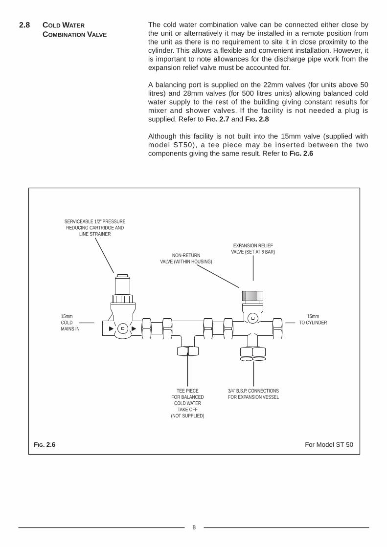
The cold water combination valve can be connected either close bythe unit or alternatively it may be installed in a remote position fromthe unit as there is no requirement to site it in close proximity to thecylinder. This allows a flexible and convenient installation. However, itis important to note allowances for the discharge pipe work from theexpansion relief valve must be accounted for.
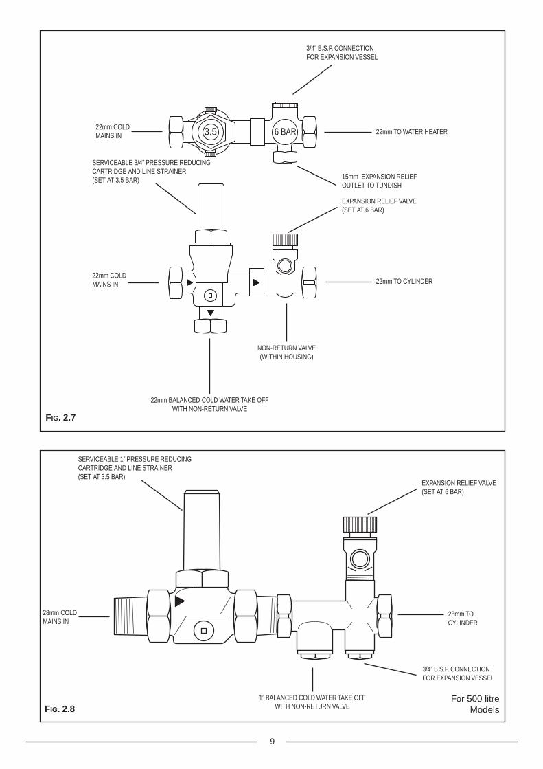
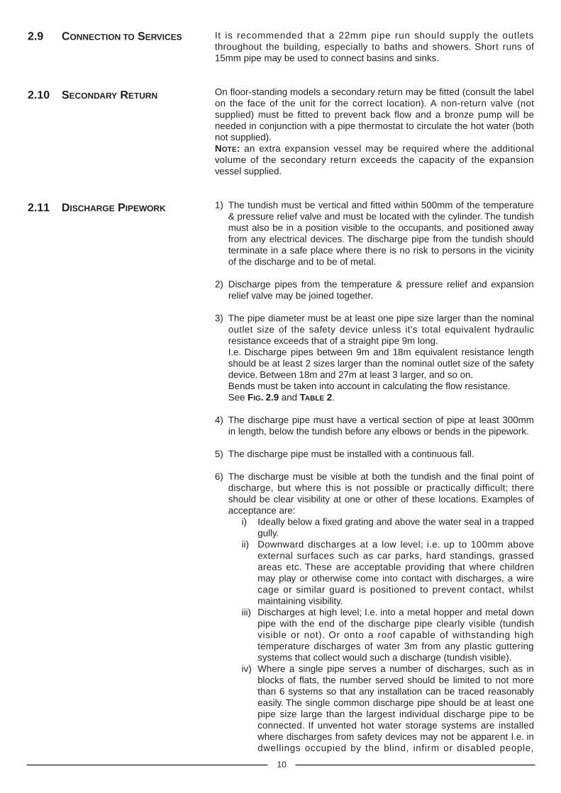
A balancing port is supplied on the 22mm valves (for units above 50litres) and 28mm valves (for 500 litres units) allowing balanced coldwater supply to the rest of the building giving constant results formixer and shower valves. If the facility is not needed a plug issupplied. Refer to FIG. 2.7 and FIG. 2.8
Although this facility is not built into the 15mm valve (supplied withmodel ST50), a tee piece may be inser ted between the twocomponents giving the same result. Refer to FIG. 2.6
2.8 COLD WATER
COMBINATION VALVE
15mmCOLDMAINS IN
15mmTO CYLINDER
3/4” B.S.P. CONNECTIONSFOR EXPANSION VESSEL
EXPANSION RELIEFVALVE (SET AT 6 BAR)
NON-RETURNVALVE (WITHIN HOUSING)
TEE PIECEFOR BALANCED
COLD WATERTAKE OFF
(NOT SUPPLIED)
SERVICEABLE 1/2” PRESSUREREDUCING CARTRIDGE AND
LINE STRAINER
For Model ST 50FIG. 2.6
9
22mm COLDMAINS IN
22mm COLDMAINS IN
22mm TO WATER HEATER
3/4” B.S.P. CONNECTIONFOR EXPANSION VESSEL
22mm TO CYLINDER
NON-RETURN VALVE(WITHIN HOUSING)
22mm BALANCED COLD WATER TAKE OFFWITH NON-RETURN VALVE
15mm EXPANSION RELIEFOUTLET TO TUNDISH
SERVICEABLE 3/4” PRESSURE REDUCINGCARTRIDGE AND LINE STRAINER(SET AT 3.5 BAR)
EXPANSION RELIEF VALVE(SET AT 6 BAR)
3.5 6 BAR
For 500 litreModels
28mm COLDMAINS IN
28mm TOCYLINDER
SERVICEABLE 1” PRESSURE REDUCINGCARTRIDGE AND LINE STRAINER(SET AT 3.5 BAR)
3/4” B.S.P. CONNECTIONFOR EXPANSION VESSEL
EXPANSION RELIEF VALVE(SET AT 6 BAR)
1” BALANCED COLD WATER TAKE OFFWITH NON-RETURN VALVE
FIG. 2.7
FIG. 2.8
10
2.9 CONNECTION TO SERVICES It is recommended that a 22mm pipe run should supply the outletsthroughout the building, especially to baths and showers. Short runs of15mm pipe may be used to connect basins and sinks.
On floor-standing models a secondary return may be fitted (consult the labelon the face of the unit for the correct location). A non-return valve (notsupplied) must be fitted to prevent back flow and a bronze pump will beneeded in conjunction with a pipe thermostat to circulate the hot water (bothnot supplied).NOTE: an extra expansion vessel may be required where the additionalvolume of the secondary return exceeds the capacity of the expansionvessel supplied.
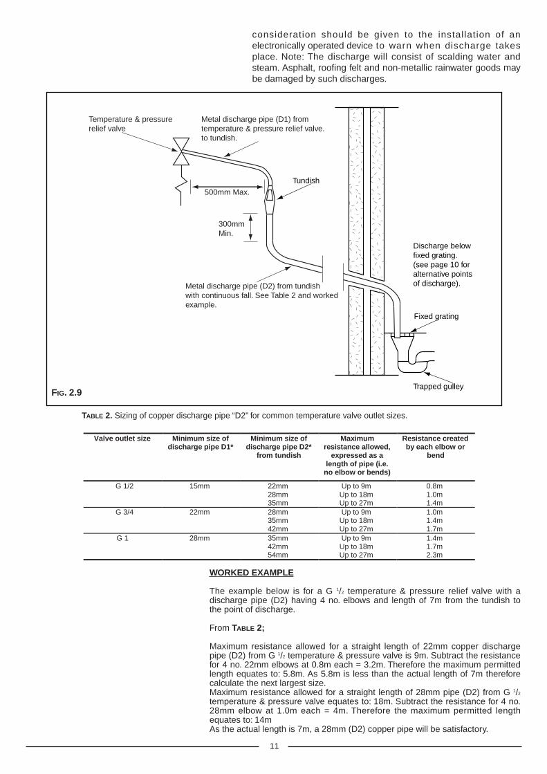
1) The tundish must be vertical and fitted within 500mm of the temperature& pressure relief valve and must be located with the cylinder. The tundishmust also be in a position visible to the occupants, and positioned awayfrom any electrical devices. The discharge pipe from the tundish shouldterminate in a safe place where there is no risk to persons in the vicinityof the discharge and to be of metal.
2) Discharge pipes from the temperature & pressure relief and expansionrelief valve may be joined together.
3) The pipe diameter must be at least one pipe size larger than the nominaloutlet size of the safety device unless it's total equivalent hydraulicresistance exceeds that of a straight pipe 9m long.I.e. Discharge pipes between 9m and 18m equivalent resistance lengthshould be at least 2 sizes larger than the nominal outlet size of the safetydevice. Between 18m and 27m at least 3 larger, and so on.Bends must be taken into account in calculating the flow resistance.See FIG. 2.9 and TABLE 2.
4) The discharge pipe must have a vertical section of pipe at least 300mmin length, below the tundish before any elbows or bends in the pipework.
5) The discharge pipe must be installed with a continuous fall.
6) The discharge must be visible at both the tundish and the final point ofdischarge, but where this is not possible or practically difficult; thereshould be clear visibility at one or other of these locations. Examples ofacceptance are:
i) Ideally below a fixed grating and above the water seal in a trappedgully.
ii) Downward discharges at a low level; i.e. up to 100mm aboveexternal surfaces such as car parks, hard standings, grassedareas etc. These are acceptable providing that where childrenmay play or otherwise come into contact with discharges, a wirecage or similar guard is positioned to prevent contact, whilstmaintaining visibility.
iii) Discharges at high level; I.e. into a metal hopper and metal downpipe with the end of the discharge pipe clearly visible (tundishvisible or not). Or onto a roof capable of withstanding hightemperature discharges of water 3m from any plastic gutteringsystems that collect would such a discharge (tundish visible).
iv) Where a single pipe serves a number of discharges, such as inblocks of flats, the number served should be limited to not morethan 6 systems so that any installation can be traced reasonablyeasily. The single common discharge pipe should be at least onepipe size large than the largest individual discharge pipe to beconnected. If unvented hot water storage systems are installedwhere discharges from safety devices may not be apparent I.e. indwellings occupied by the blind, infirm or disabled people,
2.10 SECONDARY RETURN
2.11 DISCHARGE PIPEWORK
11
consideration should be given to the installation of anelectronically operated device to warn when discharge takesplace. Note: The discharge will consist of scalding water andsteam. Asphalt, roofing felt and non-metallic rainwater goods maybe damaged by such discharges.
500mm Max.
300mm Min.
Temperature & pressure relief valve
Metal discharge pipe (D1) from temperature & pressure relief valve. to tundish.
Metal discharge pipe (D2) from tundish with continuous fall. See Table 2 and worked example.
Tundish
Fixed grating
Trapped gulley
Discharge below fixed grating. (see page 10 for alternative points of discharge).
Valve outlet size Minimum size ofdischarge pipe D1*
Minimum size ofdischarge pipe D2*
from tundish
Maximumresistance allowed,
expressed as alength of pipe (i.e.
no elbow or bends)
Resistance createdby each elbow or
bend
G 1/2 15mm 22mm28mm35mm
Up to 9mUp to 18mUp to 27m
0.8m1.0m1.4m
G 3/4 22mm 28mm35mm42mm
Up to 9mUp to 18mUp to 27m
1.0m1.4m1.7m
G 1 28mm 35mm42mm54mm
Up to 9mUp to 18mUp to 27m
1.4m1.7m2.3m
TABLE 2. Sizing of copper discharge pipe “D2” for common temperature valve outlet sizes.
WORKED EXAMPLE
The example below is for a G 1/2 temperature & pressure relief valve with adischarge pipe (D2) having 4 no. elbows and length of 7m from the tundish tothe point of discharge.
From TABLE 2;
Maximum resistance allowed for a straight length of 22mm copper dischargepipe (D2) from G 1/2 temperature & pressure valve is 9m. Subtract the resistancefor 4 no. 22mm elbows at 0.8m each = 3.2m. Therefore the maximum permittedlength equates to: 5.8m. As 5.8m is less than the actual length of 7m thereforecalculate the next largest size.Maximum resistance allowed for a straight length of 28mm pipe (D2) from G 1/2
temperature & pressure valve equates to: 18m. Subtract the resistance for 4 no.28mm elbow at 1.0m each = 4m. Therefore the maximum permitted lengthequates to: 14mAs the actual length is 7m, a 28mm (D2) copper pipe will be satisfactory.
FIG. 2.9
12
WARNINGSThe outlet from the temperature & pressure relief valve must not be used forany other purpose. This also applies to the expansion relief valve. No othervalve is to be fitted between the cold water combination valve and thecylinder.
The temperature & pressure relief valve must not be removed in anycircumstances. Any of the above will totally invalidate the guarantee.
2.12 ELECTRICAL
CONNECTION
The electrical installation must be in accordance with the current I.E.E.wiring regulations.
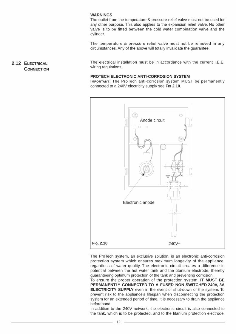
PROTECH ELECTRONIC ANTI-CORROSION SYSTEMIMPORTANT: The ProTech anti-corrosion system MUST be permanentlyconnected to a 240V electricity supply see FIG 2.10.
240V~
Electronic anode
Anode circuit
N1L
The ProTech system, an exclusive solution, is an electronic anti-corrosionprotection system which ensures maximum longevity of the appliance,regardless of water quality. The electronic circuit creates a difference inpotential between the hot water tank and the titanium electrode, therebyguaranteeing optimum protection of the tank and preventing corrosion.To ensure the proper operation of the protection system, IT MUST BEPERMANENTLY CONNECTED TO A FUSED NON-SWITCHED 240V, 3AELECTRICITY SUPPLY even in the event of shut-down of the system. Toprevent risk to the appliance’s lifespan when disconnecting the protectionsystem for an extended period of time, it is necessary to drain the appliancebeforehand.In addition to the 240V network, the electronic circuit is also connected tothe tank, which is to be protected, and to the titanium protection electrode,
FIG. 2.10
13
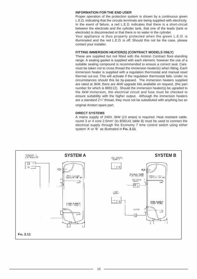
INFORMATION FOR THE END USERProper operation of the protection system is shown by a continuous greenL.E.D, indicating that the circuits terminals are being supplied with electricity.In the event of failure, a red L.E.D. indicates that there is a short-circuitbetween the electrode and the cylinder tank, that one of the leads (tank orelectrode) is disconnected or that there is no water in the cylinder.Your appliance is thus properly protected when the green L.E.D. isilluminated and the red L.E.D. is off. Should this not be the case, pleasecontact your installer.
FITTING IMMERSION HEATER(S) (CONTRACT MODELS ONLY)These are supplied but not fitted with the Ariston Contract floor-standingrange. A sealing gasket is supplied with each element, however the use of asuitable sealing compound is recommended� to ensure a correct seal. Caremust be taken not to cross thread the immersion heater(s) when fitting. Eachimmersion heater is supplied with a regulation thermostat and manual resetthermal cut-out. This will activate if the regulation thermostat fails. Under nocircumstances should this be by-passed. The immersion heaters suppliedare rated at 3kW, there are 4kW upgrade kits available on request, (the partnumber for which is 889112). Should the immersion heater(s) be ugraded tothe 4kW immersion, the electrical circuit and fuse must be checked toensure suitability with the higher output. Although the immersion heatersare a standard 21/4” thread, they must not be substituted with anything but an
original Ariston spare part.
DIRECT SYSTEMSA mains supply of 240V, 3kW (13 amps) is required. Heat resistant cable,round 3 or 4 core 2.5mm2 (to BS6141 table 8) must be used to connect theelectrical supply through the Economy 7 time control switch using eithersystem ‘A’ or ‘B’ as illustrated in FIG. 2.11.
SYSTEM A SYSTEM B
FIG. 2.11
14
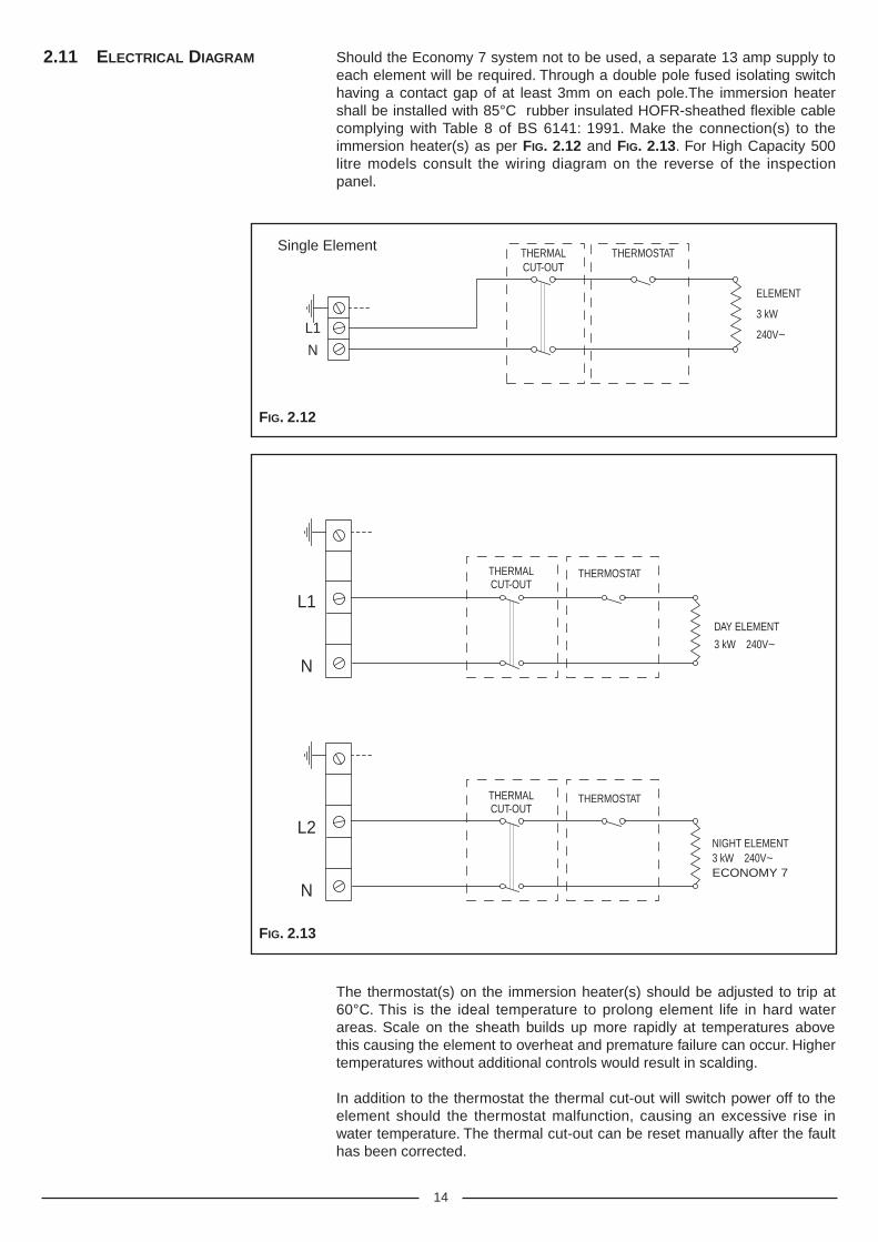
The thermostat(s) on the immersion heater(s) should be adjusted to trip at60°C. This is the ideal temperature to prolong element life in hard waterareas. Scale on the sheath builds up more rapidly at temperatures abovethis causing the element to overheat and premature failure can occur. Highertemperatures without additional controls would result in scalding.
In addition to the thermostat the thermal cut-out will switch power off to theelement should the thermostat malfunction, causing an excessive rise inwater temperature. The thermal cut-out can be reset manually after the faulthas been corrected.
THERMALCUT-OUT
L2
N
L1
N
THERMOSTAT
DAY ELEMENT
3 kW 240V~
NIGHT ELEMENT3 kW 240V~ECONOMY 7
THERMALCUT-OUT
THERMOSTAT
THERMALCUT-OUT
L1
N
THERMOSTAT
ELEMENT
3 kW
240V~
Single Element
2.11 ELECTRICAL DIAGRAM Should the Economy 7 system not to be used, a separate 13 amp supply toeach element will be required. Through a double pole fused isolating switchhaving a contact gap of at least 3mm on each pole.The immersion heatershall be installed with 85°C rubber insulated HOFR-sheathed flexible cablecomplying with Table 8 of BS 6141: 1991. Make the connection(s) to theimmersion heater(s) as per FIG. 2.12 and FIG. 2.13. For High Capacity 500litre models consult the wiring diagram on the reverse of the inspectionpanel.
FIG. 2.12
FIG. 2.13
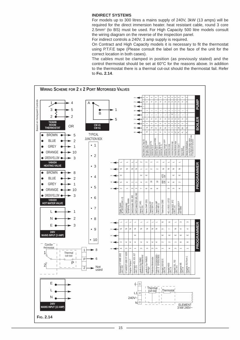
INDIRECT SYSTEMSFor models up to 300 litres a mains supply of 240V, 3kW (13 amps) will berequired for the direct immersion heater. heat resistant cable, round 3 core2.5mm2 (to BS) must be used. For High Capacity 500 litre models consultthe wiring diagram on the reverse of the inspection panel.For indirect controls a 240V, 3 amp supply is required.On Contract and High Capacity models it is necessary to fit the thermostatusing P.T.F.E tape (Please consult the label on the face of the unit for thecorrect location in both cases).The cables must be clamped in position (as previously stated) and thecontrol thermostat should be set at 60°C for the reasons above. In additionto the thermostat there is a thermal cut-out should the thermostat fail. Referto FIG. 2.14.
15
WIRING SCHEME FOR 2 X 2 PORT MOTORISED VALVES
T6360BROOM
THERMOSTAT
1 4
3 5
2 2
OR CM 41CM 51
A
B1
5
V4043HHEATING VALVE
BROWN 5
BLUE 2
GREY 1
ORANGE 10
GREEN/YELLOW 3
V4043HHOT WATER VALVE
BROWN 8
BLUE 2
GREY 1
ORANGE 10
GREEN/YELLOW 3
Hone
ywel
l ST
699B
100
26
3N
LLi
nk L
-5-8
ST 6
400/
ST 6
300
ST 6
200
34
NL
Dray
ton
Tem
pus
73
4N
L
Hors
tman
n 42
5, 5
25, 5
271
4E
NL
Link
L-2
-5
Land
is &
Gyr
RW
B23
4N
LG
lowwo
rm M
aste
rmin
d
Land
is &
Gyr
RW
B20
34
NL
Micr
ogyr
Potte
rton
Min
imin
der
34
NL
Potte
rton
EP20
00/3
000
-3
4N
LLi
nk L
-5
EP20
01/3
001
Rand
all 1
02/1
02 E
12
E5
6Li
nk 3
-6
Rand
all 4
033
42
E7
6Li
nk 1
-6
Rand
all 7
01, 7
023
1E
NL
Link
L-6
-5
Sang
amo
M5
18
E4
3Li
nk 1
-6
Sang
amo
410
Form
11
8E
43
Link
3-6
PR
OG
RA
MM
ER
64
32
1
Pegl
er S
unvic
25
EN
LSP
50/
100
(Lin
k L-
3)
Switc
hmas
ter
14
NL
Sym
phon
y, So
nata
Switc
hmas
ter 4
00, 6
003
1N
L
SWIT
CHM
ASTE
R 80
5, 9
003
1N
L
Sunv
ic ET
145
17
4E
12
Link
2-3
-6
Sunv
ic DH
P 22
016
3E
12
Towe
rchr
on F
P6
102
1Li
nk 1
-5/4
-7-9
Towe
rchr
on M
P6
102
1Li
nk 1
-4/6
-11
Towe
rchr
on 2
000
HW
HTG
NL
ON
O
N
ACL
LS52
2, L
S722
34
NL
Rand
all 9
22, 9
723
6E
NL
Link
L-2
-5
Rand
all 3
020
P4
2E
NL
and
3060
PR
OG
RA
MM
ER
64
32
1
1
Cylinderthermostat
Thermalcut-out
ELEMENT3 kW 240V~
Thermalcut-out Thermostat
1 8
6
Notused
L1
240V~
N
P
2
P2
240VMAINS INPUT (3 AMP)
L 1
N 2
E 3
240VMAINS INPUT (13 AMP)
E
L
N
• 1
• 2
• 3
• 4
• 5
• 6
• 7
• 8
• 9
• 10
TYPICALJUNCTION BOX
FIG. 2.14
Basic
Boil
ers (s
ee P
age 1
6)L
EN
LN
EBa
xi So
lo 2 3
0PF T
o 80P
F
PL
SL
EN
LL
NE
and 3
0RS
to 60
RSGl
owwo
rm E
cono
my P
lus7
S
LE
NL
LN
E(re
move
link S
L-9)
Glow
worm
Spa
cesa
ver K
FB50
9
12
EN
LL
NE
(remo
ve lin
k 12-7
)Gl
owwo
rm U
ltimate
SS
P
SL
EN
LL
NE
(remo
ve lin
k SL -
4)
Glow
worm
Fuels
aver
100F
FP
S
LE
NL
LN
E(re
move
link 7
- 12)
Halst
ead B
est ra
nge
21
EN
LL
NE
Halst
ead B
almora
l rang
e 9
6E
N12
LN
E
Halst
ead B
lenhe
im ra
nge
LP
2E
NL
LN
E
Ideal
Mexic
o Sup
er 2
PL
LB
EN
LL
NE
Myso
n Apo
llo
PL
O
NE
NL
LN
E(re
move
all li
nks)
Potte
rton P
rofile
/Sup
rima
PL
SLE
NL
LN
EFo
r ARI
STON
, Vail
lant, V
okèra
, Bu
rco M
axol
and o
ther m
akes
, refer
to ma
nufac
turers
instr
uctio
ns.
BO
ILE
R
P
UM
P
910
32
19
102
3
Bas
ed o
n H
oney
wel
l Con
trol
s
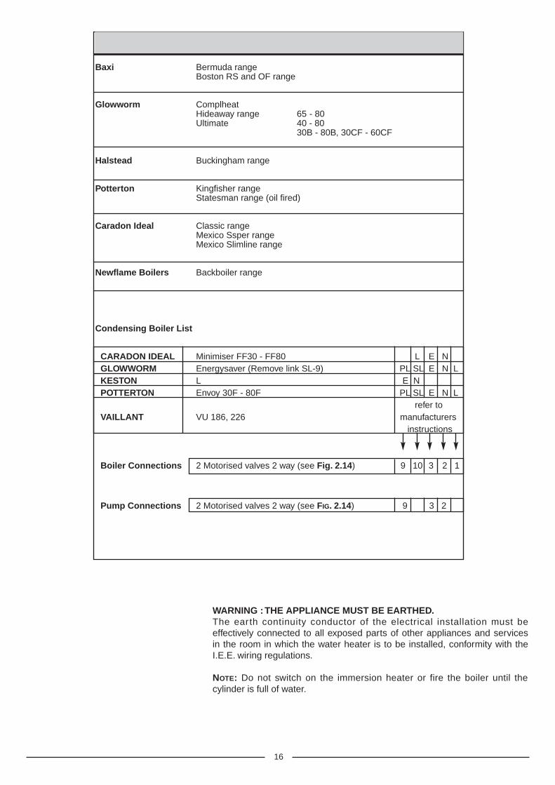
BASIC BOILER LIST
Baxi Bermuda rangeBoston RS and OF range
Glowworm ComplheatHideaway range 65 - 80Ultimate 40 - 80
30B - 80B, 30CF - 60CF
Halstead Buckingham range
Potterton Kingfisher rangeStatesman range (oil fired)
Caradon Ideal Classic rangeMexico Ssper rangeMexico Slimline range
Newflame Boilers Backboiler range
Condensing Boiler List
CARADON IDEAL Minimiser FF30 - FF80 L E NGLOWWORM Energysaver (Remove link SL-9) PL SL E N LKESTON L E NPOTTERTON Envoy 30F - 80F PL SL E N L
refer toVAILLANT VU 186, 226 manufacturers
instructions
Boiler Connections 2 Motorised valves 2 way (see Fig. 2.14) 9 10 3 2 1
Pump Connections 2 Motorised valves 2 way (see FIG. 2.14) 9 3 2
16
WARNING :THE APPLIANCE MUST BE EARTHED.The earth continuity conductor of the electrical installation must beeffectively connected to all exposed parts of other appliances and servicesin the room in which the water heater is to be installed, conformity with theI.E.E. wiring regulations.
NOTE: Do not switch on the immersion heater or fire the boiler until thecylinder is full of water.
17
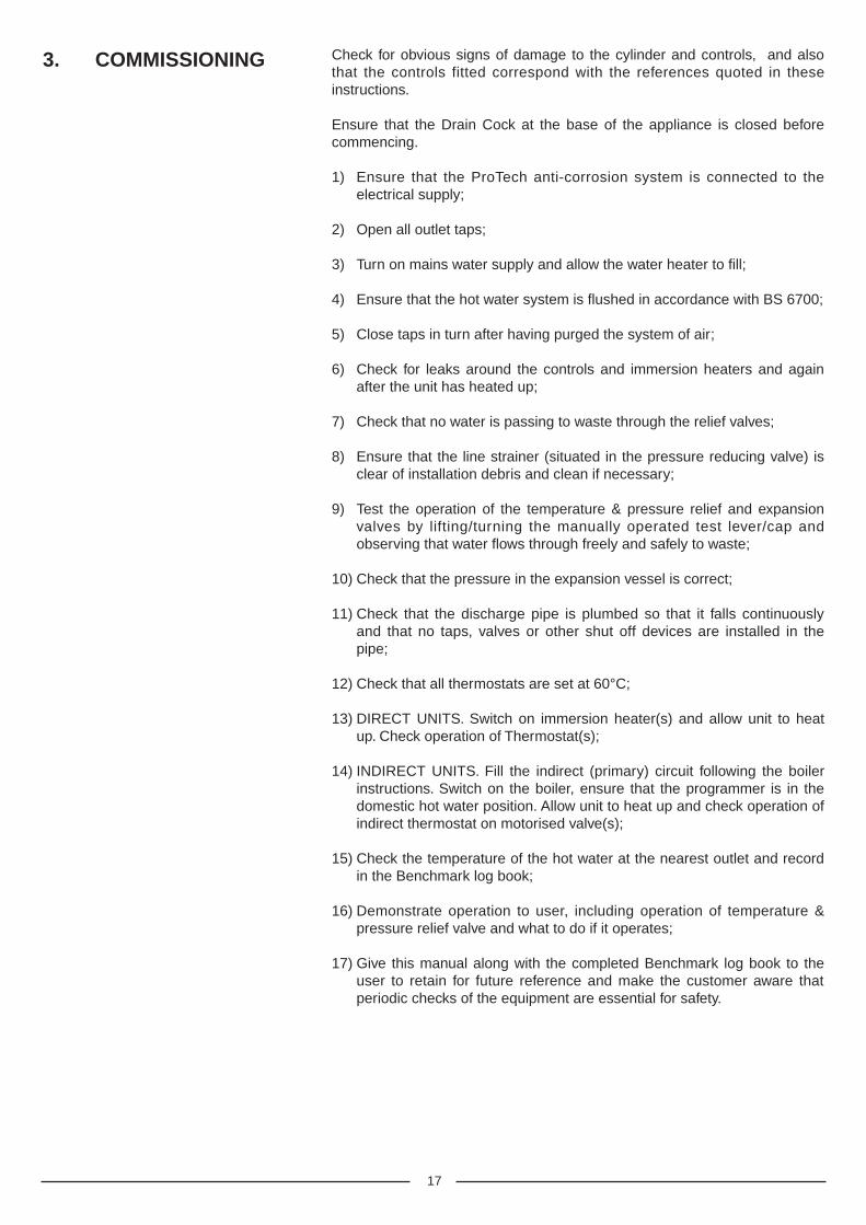
3. COMMISSIONING Check for obvious signs of damage to the cylinder and controls, and alsothat the controls fitted correspond with the references quoted in theseinstructions.
Ensure that the Drain Cock at the base of the appliance is closed beforecommencing.
1) Ensure that the ProTech anti-corrosion system is connected to theelectrical supply;
2) Open all outlet taps;
3) Turn on mains water supply and allow the water heater to fill;
4) Ensure that the hot water system is flushed in accordance with BS 6700;
5) Close taps in turn after having purged the system of air;
6) Check for leaks around the controls and immersion heaters and againafter the unit has heated up;
7) Check that no water is passing to waste through the relief valves;
8) Ensure that the line strainer (situated in the pressure reducing valve) isclear of installation debris and clean if necessary;
9) Test the operation of the temperature & pressure relief and expansionvalves by lifting/turning the manually operated test lever/cap andobserving that water flows through freely and safely to waste;
10) Check that the pressure in the expansion vessel is correct;
11) Check that the discharge pipe is plumbed so that it falls continuouslyand that no taps, valves or other shut off devices are installed in thepipe;
12) Check that all thermostats are set at 60°C;
13) DIRECT UNITS. Switch on immersion heater(s) and allow unit to heatup. Check operation of Thermostat(s);
14) INDIRECT UNITS. Fill the indirect (primary) circuit following the boilerinstructions. Switch on the boiler, ensure that the programmer is in thedomestic hot water position. Allow unit to heat up and check operation ofindirect thermostat on motorised valve(s);
15) Check the temperature of the hot water at the nearest outlet and recordin the Benchmark log book;
16) Demonstrate operation to user, including operation of temperature &pressure relief valve and what to do if it operates;
17) Give this manual along with the completed Benchmark log book to theuser to retain for future reference and make the customer aware thatperiodic checks of the equipment are essential for safety.
18
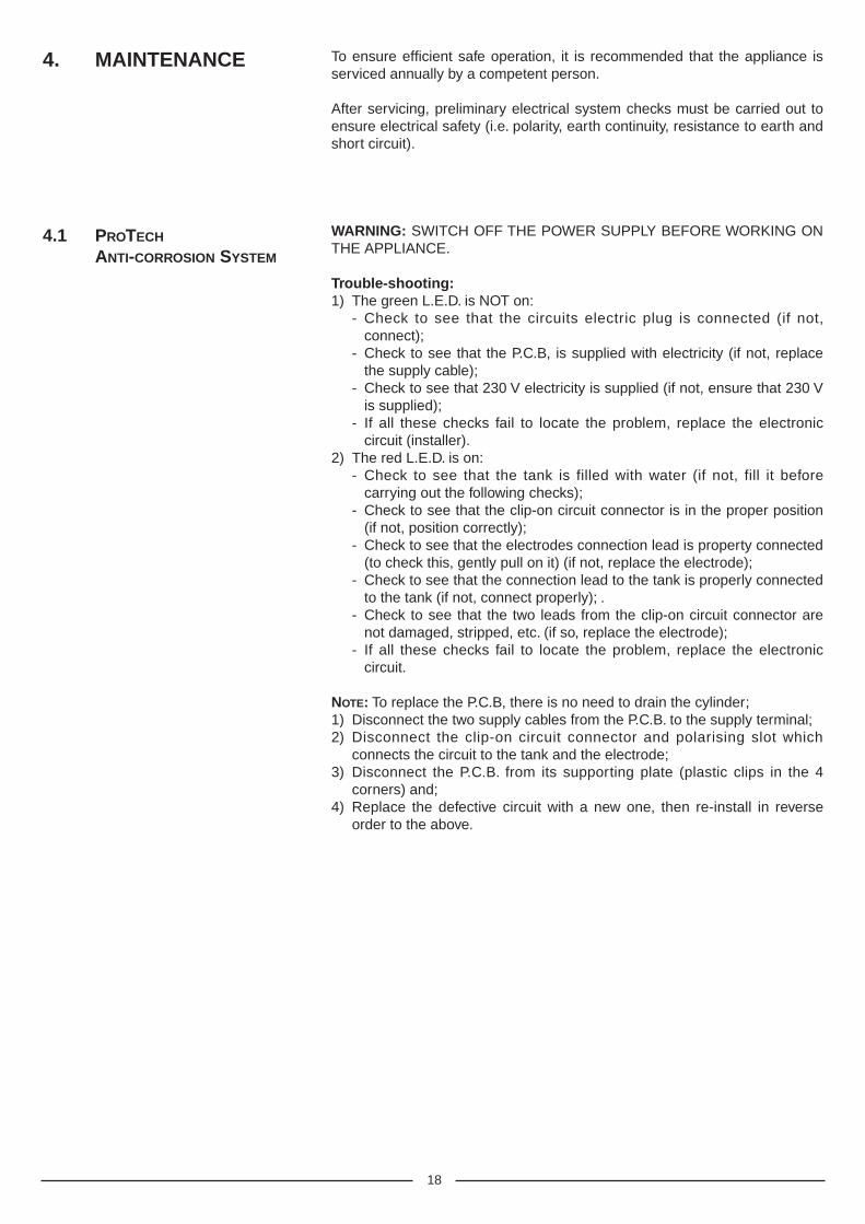
4. MAINTENANCE To ensure efficient safe operation, it is recommended that the appliance isserviced annually by a competent person.
After servicing, preliminary electrical system checks must be carried out toensure electrical safety (i.e. polarity, earth continuity, resistance to earth andshort circuit).
WARNING: SWITCH OFF THE POWER SUPPLY BEFORE WORKING ONTHE APPLIANCE.
Trouble-shooting:1) The green L.E.D. is NOT on:
- Check to see that the circuits electric plug is connected (if not,connect);
- Check to see that the P.C.B, is supplied with electricity (if not, replacethe supply cable);
- Check to see that 230 V electricity is supplied (if not, ensure that 230 Vis supplied);
- If all these checks fail to locate the problem, replace the electroniccircuit (installer).
2) The red L.E.D. is on:- Check to see that the tank is filled with water (if not, fill it before
carrying out the following checks);- Check to see that the clip-on circuit connector is in the proper position
(if not, position correctly);- Check to see that the electrodes connection lead is property connected
(to check this, gently pull on it) (if not, replace the electrode);- Check to see that the connection lead to the tank is properly connected
to the tank (if not, connect properly); .- Check to see that the two leads from the clip-on circuit connector are
not damaged, stripped, etc. (if so, replace the electrode);- If all these checks fail to locate the problem, replace the electronic
circuit.
NOTE: To replace the P.C.B, there is no need to drain the cylinder;1) Disconnect the two supply cables from the P.C.B. to the supply terminal;2) Disconnect the clip-on circuit connector and polarising slot which
connects the circuit to the tank and the electrode;3) Disconnect the P.C.B. from its supporting plate (plastic clips in the 4
corners) and;4) Replace the defective circuit with a new one, then re-install in reverse
order to the above.
4.1 PROTECH
ANTI-CORROSION SYSTEM
19
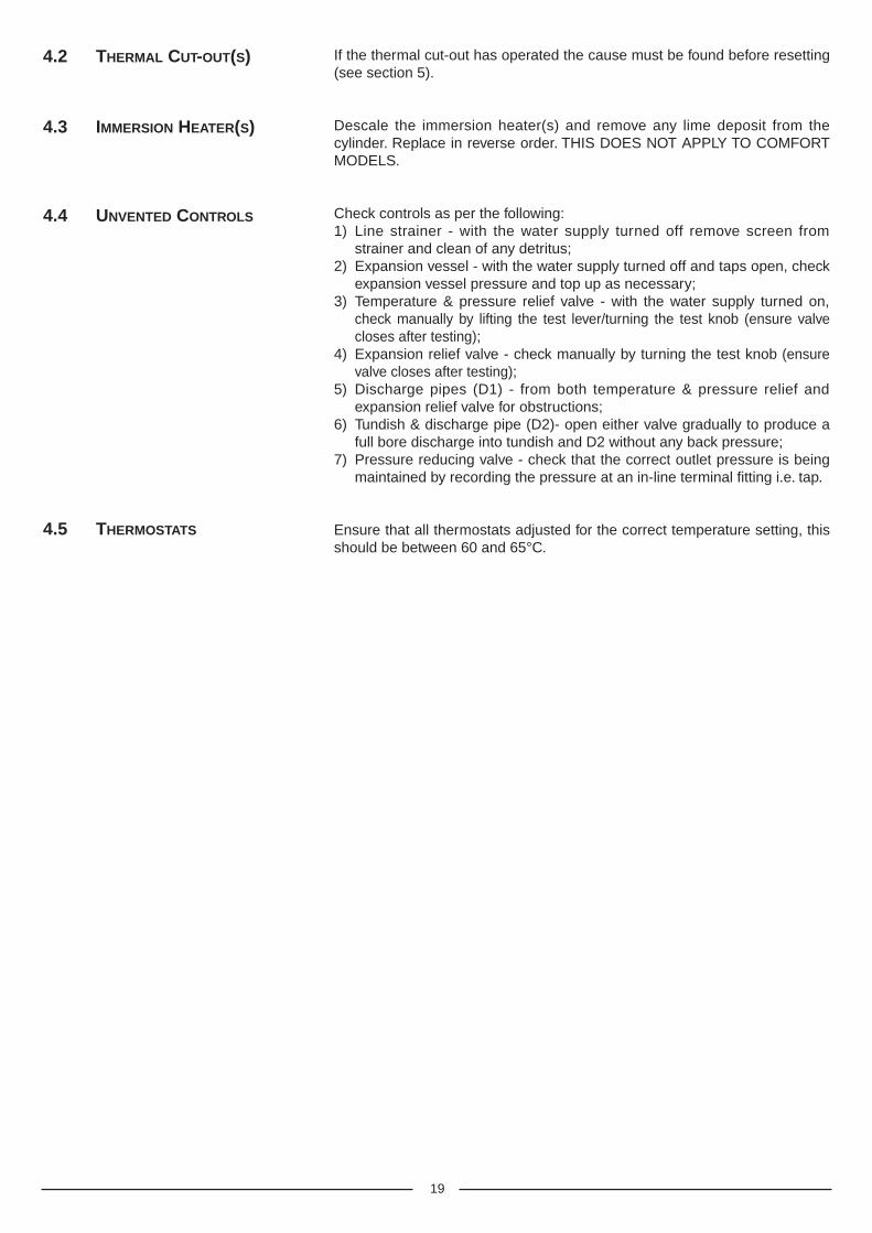
If the thermal cut-out has operated the cause must be found before resetting(see section 5).
Descale the immersion heater(s) and remove any lime deposit from thecylinder. Replace in reverse order. THIS DOES NOT APPLY TO COMFORTMODELS.
Check controls as per the following:1) Line strainer - with the water supply turned off remove screen from
strainer and clean of any detritus;2) Expansion vessel - with the water supply turned off and taps open, check
expansion vessel pressure and top up as necessary;3) Temperature & pressure relief valve - with the water supply turned on,
check manually by lifting the test lever/turning the test knob (ensure valvecloses after testing);
4) Expansion relief valve - check manually by turning the test knob (ensurevalve closes after testing);
5) Discharge pipes (D1) - from both temperature & pressure relief andexpansion relief valve for obstructions;
6) Tundish & discharge pipe (D2)- open either valve gradually to produce afull bore discharge into tundish and D2 without any back pressure;
7) Pressure reducing valve - check that the correct outlet pressure is beingmaintained by recording the pressure at an in-line terminal fitting i.e. tap.
Ensure that all thermostats adjusted for the correct temperature setting, thisshould be between 60 and 65°C.
4.2 THERMAL CUT-OUT(S)
4.3 IMMERSION HEATER(S)
4.4 UNVENTED CONTROLS
4.5 THERMOSTATS
20
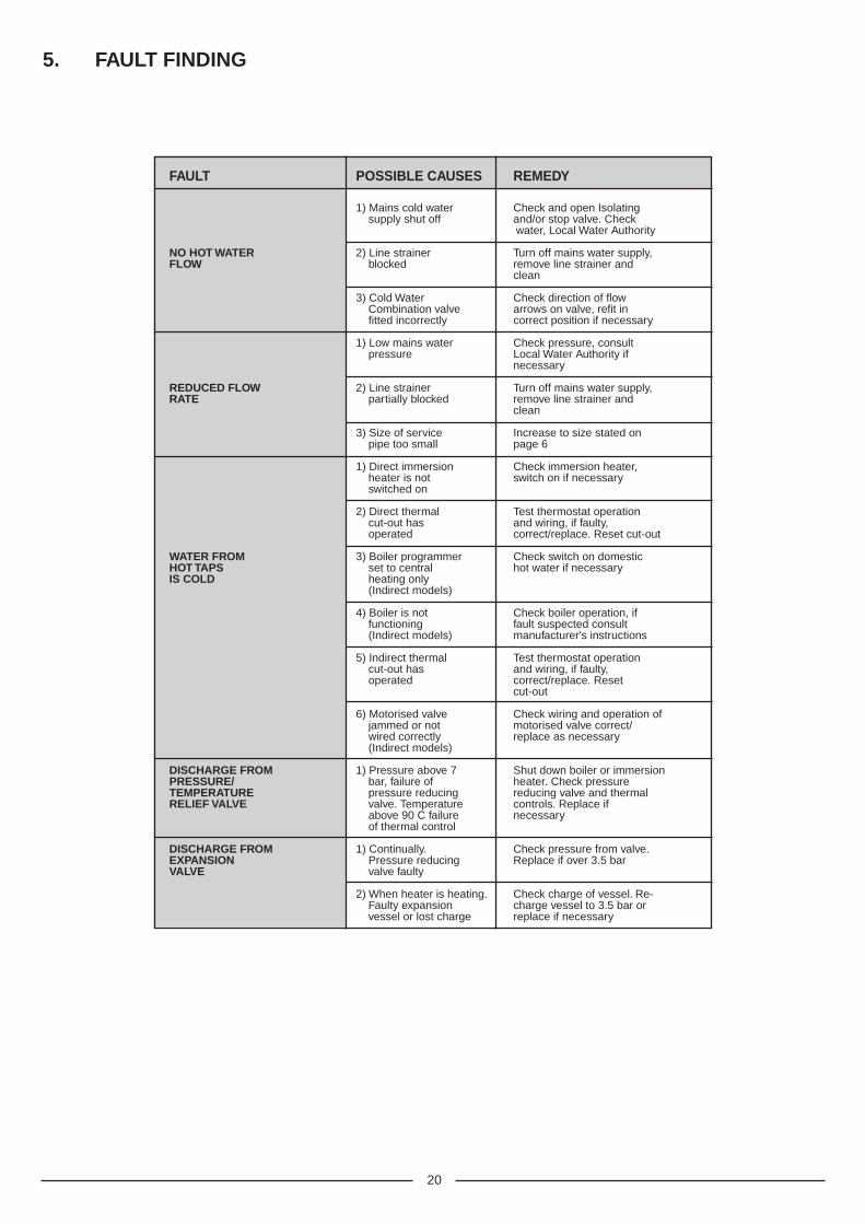
FAULT POSSIBLE CAUSES REMEDY
1) Mains cold water Check and open Isolatingsupply shut off and/or stop valve. Check
water, Local Water Authority
NO HOT WATER 2) Line strainer Turn off mains water supply,FLOW blocked remove line strainer and
clean
3) Cold Water Check direction of flowCombination valve arrows on valve, refit infitted incorrectly correct position if necessary
1) Low mains water Check pressure, consultpressure Local Water Authority if
necessary
REDUCED FLOW 2) Line strainer Turn off mains water supply,RATE partially blocked remove line strainer and
clean
3) Size of service Increase to size stated onpipe too small page 6
1) Direct immersion Check immersion heater,heater is not switch on if necessaryswitched on
2) Direct thermal Test thermostat operationcut-out has and wiring, if faulty,operated correct/replace. Reset cut-out
WATER FROM 3) Boiler programmer Check switch on domesticHOT TAPS set to central hot water if necessaryIS COLD heating only
(Indirect models)
4) Boiler is not Check boiler operation, iffunctioning fault suspected consult(Indirect models) manufacturer's instructions
5) Indirect thermal Test thermostat operationcut-out has and wiring, if faulty,operated correct/replace. Reset
cut-out
6) Motorised valve Check wiring and operation ofjammed or not motorised valve correct/wired correctly replace as necessary(Indirect models)
DISCHARGE FROM 1) Pressure above 7 Shut down boiler or immersionPRESSURE/ bar, failure of heater. Check pressureTEMPERATURE pressure reducing reducing valve and thermalRELIEF VALVE valve. Temperature controls. Replace if
above 90 C failure necessaryof thermal control
DISCHARGE FROM 1) Continually. Check pressure from valve.EXPANSION Pressure reducing Replace if over 3.5 barVALVE valve faulty
2) When heater is heating. Check charge of vessel. Re-Faulty expansion charge vessel to 3.5 bar orvessel or lost charge replace if necessary
5. FAULT FINDING
21
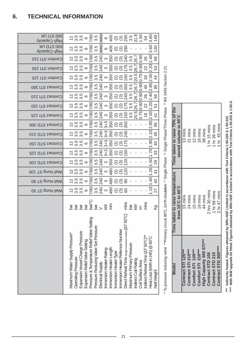
6. TECHNICAL INFORMATION
12 3.5
3.5 6
7/90 3.5
240 3 480
(1)
(3)
60 - - - -1.
15 27
12 3.5
3.5 6
7/90 3.5
240 3 480
(1)
(3)
120 - - - -
1.26 41
* To
pre
ssur
e re
duci
ng v
alve
**P
rimar
y ci
rcui
t 80°
C, 1
m3 /h
circ
ulat
ion.
(1)S
ingl
e P
hase
(2)S
ingl
e P
hase
/Thr
ee P
hase
(3)B
S 3
456
Sec
tion
2.21
Wall Hung ST 50
Wall Hung ST 80
Wall Hung ST 100
Contract STD 100
Contract STD 125
Contract STD 150
Contract STD 210
Contract STD 300
Contract STI 125
Contract STI 150
Contract STI 210
Contract STI 300
Comfort STI 125
Comfort STI 150
Comfort STI 210
High Capacity500 STD UKHigh Capacity500 STI UK
12 3.5
3.5 6
7/90 3.5
240 3 480
(1)
(3)
90 - - - -1.
40 40
12 3.5
3.5 6
7/90 3.5
240 3 350
(1)
(3)
120 - - - -
1.50 29
12 3.5
3.5 6
7/90 3.5
240
3+3
350
(1)
(3)
150 - - - -
1.70 33
12 3.5
3.5 6
7/90 3.5
240
3+3
350
(1)
(3)
175 - - - -
1.90 40
12 3.5
3.5 6
7/90 3.5
240
3+3
350
(1)
(3)
350 - - - -
2.85 85
12 3.5
3.5 6
7/90 3.5
240
3+3
350
(1)
(3)
240 - - - -
2.10 45
12 3.5
3.5 6
7/90 3.5
240 3 350
(1)
(3)
150
3.5
20.5
0.75 18 2.00 41
12 3.5
3.5 6
7/90 3.5
240 3 350
(1)
(3)
175
3.5
26.7
0.90 22 2.20 51
12 3.5
3.5 6
7/90 3.5
240 3 350
(1)
(3)
240
3.5
26.7
0.90 26 2.40 56
12 3.5
3.5 6
7/90 3.5
240 3 350
(1)
(3)
150
3.5
20.5
0.75 18 2.00 44
12 3.5
3.5 6
7/90 3.5
240 3 350
(1)
(3)
350
3.5
26.7
0.90 40 2.85 95
12 3.5
3.5 6
7/90 3.5
240 3 350
(1)
(3)
175
3.5
26.7
0.90 22 2.20 53
12 3.5
3.5 6
7/90 3.5
240 3 350
(1)
(3)
240
3.5
26.7
0.90 26 2.40 58
12 3.5
3.5 6
7/90 3.5
240/4
156 400
(2)
(3)
290 - - - -
3.60
130
12 3.5
3.5 6
7/90 3.5
240/4
156 400
(2)
(3)
290
3.5
31.8
1.50 54 3.60
149
Mo
del
Tim
e ta
ken
to
rai
se t
emp
erat
ure
fro
m 1
5˚C
to
65˚
CT
ime
take
n t
o r
aise
70%
of
the
sto
red
vo
lum
e to
65˚
CC
on
trac
t S
TI 1
25**
*15
min
s13
min
sC
on
trac
t S
TI 2
10**
*24
min
s21
min
sC
om
fort
ST
I 12
5***
15 m
ins
12 m
ins
Co
mfo
rt S
TI
210*
**19
min
s16
min
sH
igh
Cap
acit
y 50
0 S
TI*
**44
min
s38
min
sC
on
trac
t S
TD
100
2 hr
s 30
min
s1
hr 1
5 m
ins
Co
ntr
act
ST
D 2
10C
on
trac
t S
TD
300
****
1 hr
58
min
s2
hr 4
7 m
ins
1 hr
39
min
s1
hr 4
5 m
ins
***
In
dir
ectl
y h
eate
d. F
igu
res
ob
tain
ed b
y W
Rc-
NS
F L
imit
ed in
acc
ord
ance
wit
h T
est
Cri
teri
a 1-
50-2
20 &
1-5
0-22
2.**
** W
ith
4kW
up
gra
de
kit
fitt
ed. F
igu
res
ob
tain
ed b
y W
Rc-
NS
F L
imit
ed in
acc
orc
dan
ce w
ith
Tes
t C
rite
ria
1-50
-220
& 1
-50-
222.
Max
imum
Wat
er S
uppl
y P
ress
ure*
bar
Ope
ratin
g P
ress
ure
bar
Exp
ansi
on V
esse
l Cha
rge
Pre
ssur
eba
rE
xpan
sion
Rel
ief V
alve
Set
ting
bar
Pre
ssur
e &
Tem
pera
ture
Rel
ief V
alve
Set
ting
bar/°
CP
ress
ure
Red
ucin
g Va
lve
Set
Pre
ssur
eba
rE
lect
rical
Sup
ply
VIm
mer
sion
Hea
ter R
atin
gkW
Imm
ersi
on H
eate
r Len
gth
mm
Imm
ersi
on H
eate
r Typ
eIm
mer
sion
Hea
ter R
efer
nce
Num
ber
Dire
ct R
ehea
t Tim
e (S
ingl
e Im
mer
sion
Hea
ter)(∆
T 50
°C)
min
sM
axim
um P
rimar
y P
ress
ure
bar
Indi
rect
Coi
l Rat
ing
kWC
oil S
urfa
ce A
rea
m2
Indi
rect
Reh
eat T
ime
(∆T
50°C
)**
min
sH
eat L
oss
(kW
h in
24h
) @ 6
0°C
Net
t Wei
ght
Kg

22
NOTES

23
NOTES

Manufacturer: MTS Benelux sa/nv - Belgium
Commercial subsidiary: MTS (GB) LIMITEDMTS BuildingHughenden AvenueHigh WycombeBucks. HP13 5FT
Telephone: (01494) 755600
Fax: (01494) 459775
Internet: www.ariston.co.uk
E-mail: [email protected]
Technical Service Hot Line: (0870) 241 8180
Customer Service Help Desk: (0870) 600 9888
Aris
ton
Unv
ente
d C
ylin
der
(Pro
tech
) M
anua
l 01/
01/2
004