Embed Size (px)
Citation preview

DIRECTIONAL CONTROLS
1
2
Conventional T ype G-Series Valve
Conventional T ype G-Series Valve
EG-DSG-01 G-DSHG-04
W
Solenoid Valve
SOL ON
P T
Piping vibration
Machine vibration
Oil leakage Large machining
Oil Hammering
W
P T
SOL ON
No vibrationNo oil leakageEnhanced m achining accuracy
Improvement
Jerk at start up
Sudden stop, causing shock
Shaking
Improvement
Slow start
No shaking
Slow stop
No shaking
Stopping accuracy enhanced
Still
Up to 25 MPa (3630 PSI), 250 L /m in (66.1 U.S.GPM)
No.1
"G" SERIES SHOCKLESS TYPE SOLENOID OPERATED DIRECTIONAL VALVES
Pub. EC-0405
Sub-plate Mounting
The G-Series Solenoid Operated Directional Valves incorporate electronic circuits to enable adjustment of the spool shifting time. As the shifting time of the G-Series valves can be adjusted, it can be set at an optimal level to minimise shocks to the machine.
"G" SERIES SHOCKLESS TYPE SOLENOID CONTROLLED PILOT OPERATED
DIRECTIONAL VALVES
G-DSG-01/03 (1/8, 3/8)
G-DSHG-04/06 (1/2, 3/4)
Reduces o i l ham m ering during spool changeover.
Reduces shock caused by acceleration and deceleration

DIRECTIONAL CONTROLSSystem Diagram / SOL signals and flow patterns
HALT
SOL a
SOL b
Adj . Volum e "OFF ADJ"
DC Power Supply
24 V DC
Shifting Signal
Deceleration Start SignalProgrammable
Controller
+
-
Adj . Volum e "ON T"
Adj . Volum e "OFF T"
Adj . Volum e "MIN"
Output Current Check (to 0V)
Adj . Volum e "OFF ADJ"
Adj . Volum e "ON T"
Adj . Volum e "OFF T"
A B
P T
SOL a
SOL b
ON T
(Max. 1s)
OFF T
OFF ADJ
ONOFF
OFF
ON T OFF T
ONOFF
OFF ADJ
A B
P TPattern of Flow
SOL a
SOL b
ON
HALT
ON
A B
P T
A B
P T
ON ON
OFF
OFF
OFF OFF
ON T
MIN
OFF T
MIN
ON T OFF T
OFF ADJ
Hold for 0 . 1 se c ond or l onge r
Max. 60s
Pattern of Flow
(Max. 1s)
(Max. 1s) (Max. 1s)
OFF ADJ
Max. 60s(Max. 1s)
(Max. 1s)
(Max. 1s) (Max. 1s)
Hold for 0 . 1 se c ond or l onge r
No.2
Relationships betw een SOL signals and flow patternsWithout HALT functions
"G" Series Shockless Type Solenoid Operated / Solenoid Controlled Pilot Operated Directional Valves
With HALT functions
System Diagram (Example of sink type w iring)
The m inim um adjustm ent volum e is com m on for SOL a and b, and it is not possible to set a different volum e for each SOL a and b individually . If the HALT functions are not used, set the m inim um adjustm ent volum e to zero.

DIRECTIONAL CONTROLS
E
Hydraulic Fluids / Instructions
P T B A
ba
(Exam ple)
G-DSG valve fully opens after the ON T duration.
To adjust maximum flow rates, with "G" series solenoid operated direc-tional valves (G-DSG-01/03), flow control valves such as throttle check modular valves are used. With "G" series solenoid controlled pilot operated directional valves (G-DSHG-04/06), maximum flow rates can be adjusted without flow control valves but by using a model with stroke adjustment (option).
Max. 60 s
MIN
ONOFFOFF
OFFOFF TON
SOL
HALT
Flow Rate
0
Hold for 0.1 second or longer
If no HALT signal is set on within 60 seconds of the end of OFF T, the flow rate decreases gradually.
Petroleum base oils
Synthetic fluids
Water containing fluids
Use fluids equivalent to ISO VG 32 or VG 46.Use phosphate ester or polyol ester fluid. When phosphate ester fluid is used, prefix "F-" to the model number because the special seals (fluororubber) are required to be used.Use water-glycol fluids or W/O emulsion type fluids.
Hydraulic Fluids
Recommended Viscosity and Oil Temperatures2 Viscosity ranging between 15 - 200 mm /s (77 - 927 SSU).
Oil temperatures between -15/+60°C (5 - 140°F). Use hydraulic fluids which satisfy the recommended viscosity and oil temperatures given above.
Control of ContaminationDue caution must be paid to maintaining control over contamination of the hydraulic fluids which may otherwise lead to breakdowns and shorten the life of the valves. Please maintain the degree of contamination within NAS 1638-Grade 12. Use 25 µm or finer line filter.
"G" Series Shockless Type Solenoid Operated / Solenoid Controlled Pilot Operated Directional Valves
No.3
InstructionsAdjustment of max imum flow rateThe G-Series Solenoid Operated Directional Valves cannot be adjusted for maximum flow rates. To adjust maximum flow rates, use flow control valves. In G-series solenoid controlled pilot operated direc-tional valves (G-DSHG-04/06), the maximum flow rate can be adjusted by use of the valve with stroke adjust-ment screw of optional extra.
How to use HALT functionsThe HALT functions are used to drive the actuator at a low speed to the stop position while keeping a slight flow after OFF T. A flow rate (min. flow rate) during a low-speed operation can be set with the minimum adjusting volume (The minimum adjusting volume is common for SOL a and b. Individual setting is not possible for SOL a and b.) When HALT signal is on, the min. flow rate becomes zero and the actuator stops. Here, take care to keep the HALT signal on for longer than 0.1 second. The min. flow rate gets to "0" after about 60 seconds following the OFF T. If the HALT functions are not used, set the minimum adjusting volume to zero. The HALT functions are not applicable to the spool function "2B7".
Fluid TypesAny type of hydraulic fluids listed in the table below can be used.
Note: For use with hy draulic fluids other than those listed above, please consult y our Yuken representatives in advance.

DIRECTIONAL CONTROLSInstructions
a b
W
If knocking occurs, use an external drain type.
0 MPa
0
Tank Line Back Pres.
PSI
Ope
ratin
g fo
rce
0
N
0
lbs.
1 2 3 4
200 400
50
100
150
10
20
30
No.4
Precautions in case pilot controlled check valves are used
"G" Series Shockless Type Solenoid Operated / Solenoid Controlled Pilot Operated Directional Valves
In a hydraulic circuit where a pilot controlled check valve is used, there is a possibility that the knocking will arise on the pilot controlled check valve during deceleration depending on the largeness of load inertia, the state of piping and the length of "Off T" time etc.
Air bleedingTo achieve a stable "shockless" effect, discharge air by loosening the air vent and fill the iron core of the solenoid with fluid. Each solenoid has two air vents, loosen either one. After air discharge, be sure to retighten the air vent.
Tank piping (for G-DSG-01/03)Do not connect the tank line to any line subject to a surge pressure. To obtain a stable "shockless" effect, take care not to allow the fluid in the iron core of the solenoid to flow out. To ensure this, it is best to use check valves having a cracking pressure of about 0.035 MPa (5 PSI).
Manual shiftingIf no shifting signal voltage is given to the valve in an initial operation or an electrical fault, temporary valve shifting can be carried out by pushing the manual operation push pin. In addition, note that if the back pressure of the tank line increases, manual operation of the push pin gets harder.
Drain piping (for G-DSHG-04/06)Allowable back pressure is 3 MPa (440 PSI). Take care to eliminate pressure fluctuation and keep the pressure as low as possible. To ensure this, it is best to use check valves having a cracking pressure of about 0.035 MPa (5 PSI). Be sure to hold the end of the pipe in the fluid.
Mounting PostureThere are no restrictions on mounting posture for these valves.

DIRECTIONAL CONTROLS
1. 2.
E1
2
Specifications
Electronic Circuit
DescriptionsModel Num bers
G-DSG-01-∗∗∗-∗-50/5090 G-DSG-03-∗∗∗-∗-50/5090
Max. Flow
Max. Operating Pres.
Max. T-Line Back Pres. MPa (PSI)
MPa (PSI)
L /m in (U.S.GPM)
Voltage
Input Power at 24V
Voltage
Current
Input interface
Electric Power Supply
Shifting signal, low speed operation halt signal (can be used in com m on with electric power supply ).
Shifting tim e range (for ON and OFF)
Low speed operation flow rate (m in. flow rate) range (for SOL a and b) L /m in (U.S.GPM)
Low speed operation flow rate (m in. flow rate) hold tim e
Am bient Tem perature
Approx. MassSingle SolenoidDouble Solenoid
10 (2.6), 20 (5.3), 30 (7.9), 40 (10.6) 40 (10.6), 60 (15.9), 80 (21.1)
25 (3630)
16 (2320)
25 (3630)
16 (2320)
24 V DC (21 - 28 V DC Included Ripple): Use a stable power supply
36 W 36 W
5 - 48 V DC (Use a stable power supply )
Constant at 10 m A (A constant-current circuit is used)
Sink Ty pe, Source Ty pe
0.1 - 1 s 0.3 - 1 s
0.5 - 5 (.13 - 1.3) 1 - 10 (.26 - 2.6)
Max. 60 s (After 60 seconds, the flow rate decreases gradually .)
0 - 50 °C (32 - 122 °F) with circulated air
2.1 kg (4.6 lbs.) 3.0 kg (6.6 lbs.)
5.3 kg (11.7 lbs.) 7.5 kg (16.5 lbs.)
Specifications
No.5
The m axim um flow rates m ay vary according to the operating pressure. Refer to Maxim um Flow Rates Characteristics on pages 7 and 8 for details. At pressures m ore than 21 MPa (3050 PSI), the "shockless effect" is slightly less if com pared it with that at 16 MPa (2320 PSI).
"G" Series Shockless Type Solenoid Operated Directional Valves
Sub-plate MountingG-DSG-01/03

DIRECTIONAL CONTROLS
Model Number Designation / Others
Valve Model
Num bers
Japanese Standard "JIS"Sub-plate
Model Num bersThread
SizeDSGM-01-30 DSGM-01X-30 DSGM-01Y-30 DSGM-03-40 DSGM-03X-40 DSGM-03Y-40
Rc 1/8 Rc 1/4 Rc 3/8 Rc 3/8 Rc 1/2 Rc 3/4
European Design StandardSub-plate
Model Num bersThread
SizeSub-plate
Model Num bers
N. Am erican Design StandardThread
Size0.8 (1.8) 0.8 (1.8) 0.8 (1.8) 3.0 (6.6) 3.0 (6.6)
4.7 (10.4)
Approx. Mass
kg (lbs.)
G-DSG-01
G-DSG-03
DSGM-01-3080 DSGM-01X-3080 DSGM-03-2180 DSGM-03X-2180 DSGM-03Y-2180
1/8 BSP.F 1/4 BSP.F
3/8 BSP.F 1/2 BSP.F 3/4 BSP.F
DSGM-01-3090 DSGM-01X-3090 DSGM-01Y-3090 DSGM-03-2190 DSGM-03X-2190 DSGM-03Y-2190
1/8 NPT 1/4 NPT 3/8 NPT 3/8 NPT 1/2 NPT 3/4 NPT
M5 × 45 Lg. No.10-24 UNC × 1-3/4 Lg.
Socket Head Cap Screw (4 pcs.)Japanese Standard "JIS" & European Design Standard
Model Num bers N. Am erican Design Standard Tightening Torque
M6 × 35 Lg. 1/4-20 UNC × 1-1/2 Lg.G-DSG-01G-DSG-03
5-7 Nm (44-62 in. lbs.)12-15 Nm (106-133 in. lbs.)
a bA B
P T
a bA B
P T
3C2
3C40
A B
P T
b
2B7
a bA B
P T
3C2
a bA B
P T
3C40
A B
P T
b
2B7
G-DSGG Series Shockless Ty pe Solenoid Operated Directional Valve, Sub-plate Mounting
G-DSG -01
Valve Size
01
Series Num ber
:
-50
Design Num ber
∗Design
Standards
Refer to
50
03 50
-L
Models with Alternate Offset Solenoid
A B
P Ta
-10
Metred Flow Capacity
-2B7
Spool Ty pe
-S
Input Interface
Model Number Designation
"G" Series Shockless Type Solenoid Operated Directional Valves
G-DSG-01/03
No.6
Sub-plate
Sub-plates are available. Specify the sub-plate m odel num ber from the table above. W hen sub-plates are not used, the m ounting surface should have a good m achined finish.
Attachment (Mtg. Bolt)Four socket head cap screws in the table below are included.
Design Standards: None 90
Japanese Standard "JIS" and European Design Standard N. Am erican Design Standard
........... ...............
None 10 20
: : :
40 L /m in 10 L /m in 20 L /m in
LApplicable only for 2B7
(Om it if not required)
None:Sink Ty pe (Standard)
S:Source Ty pe
None 10 20
: : :
30 L /m in 10 L /m in 20 L /m in
None 40 60
: : :
80 L /m in 40 L /m in 60 L /m in
None 40
: :
60 L /m in 40 L /m in

DIRECTIONAL CONTROLS
E
Performance Characteristics
Viscosity2 m m /s
SSUFactor
15 77
0.84
20 98
0.91
30 141 1.00
40 186 1.07
50 232 1.14
60 278 1.19
70 324 1.24
80 371 1.28
90 417 1.32
100 464 1.35
PAB
BA
T PAB
BA
T
B
TP
A B
TP
A
100ms
OFF
ON
200 msON
OFF
0 3000 3630 PSIPressure
20001000
0 5 10 15 25 MPa20
2
0
4
6
8
10
0
10
20
30
40
Max
.Flo
w
U.S.GPML/min
Direction of Flow
P→B
P
A B
TP
A B
T
P→A
40 L/min Type
20 L/min Type
10 L/min Type
Direction of Flow
P
A B
T
P→A
P
A B
T
P→B
Direction of Flow
Direction of Flow
10 L/min Type
0 30003630 PSIPressure
20001000
0 5 10 15 25 MPa200
10
20
30
40U.S.GPM
L/min
2
0
4
6
8
10
Max
.Flo
w
10 L/min TypeP→A,P→BA→T,B→T
20 L/min Type
P→BP→A
A→TB→T
40 L/min TypeP→AP→B
40 L/min TypeA→TB→T
10 L/min Type
P→BP→A
A→TB→T
20 L/min Type
A→TB→T
20 L/min Type
P→BP→A 30 L/min Type
P→BP→A
30 L/min TypeA→TB→T
1.0PSI MPa
0.8
0.6
0.4
0.2
0
40
0
80
120
140
0 10 30 L/min20 40
Flow Rate0 2 6 U.S.GPM4 108
0 10 30 L/min20
Flow Rate0 2 6 U.S.GPM4 8
PSIMPa
1.6
1.2
0.8
0.4
00
240
40
80
120
160
200
ON
20
100
30
420
68
SOL
HALT
Flow
Rat
e
OFF
Volume "MIN" Position
Volume "ON T" Position
Volume "OFF T" Position
Volume "OFF T" Position
Volume "ON T" Position
ON
100 ms
OFFSOL
20
100
30
24
8
2
8
Flow
Rat
e
20
10
3064
0
6P
A B
T
P
A B
T
2010
0
30
420
68
SOL
L/minU.S.GPM
Flow
Rat
e
02468
10
02468
10
0357
10
0357
10 68
50
30 L/min Type
20 L/min Type
Pres
sure
Dro
p
P
Pres
sure
Dro
p
P
L/minU.S.GPM
L/minU.S.GPM
No.7
"G" Series Shockless Type Solenoid Operated Directional Valves
G-DSG-01
Hydraulic Fluid: Viscosity 2 30 m m /s (141 SSU), Specific Gravity 0.850Maximum Flow Rate
Pressure Drop
G-DSG-01-∗ 3C2 3C40 - G-DSG-01-∗-2B7
G-DSG-01-∗ 3C2 3C40 - G-DSG-01-∗-2B7
For any other viscosity, multiply the factors in the table right.For any other specific gravity (G'), the pressure drop ( P') may be obtained from the formula below.
P'= P (G'/0.850)
Shifting Characteristics Low Speed Operating Flow CharacteristicsSupply Pressure : 16 MPa (2320 PSI) Flow Rate : 30 L/min (7.9 U.S.GPM)
Supply Pressure : 16 MPa (2320 PSI) Flow Rate : 30 L/min (7.9 U.S.GPM)
2B7
3C2, 3C40
DIRECTIONAL CONTROLS
Performance Characteristics
Viscosity2 m m /s
SSUFactor
15 77
0.84
20 98
0.91
30 141 1.00
40 186 1.07
50 232 1.14
60 278 1.19
70 324 1.24
80 371 1.28
90 417 1.32
100 464 1.35
Model Num bers Pressure Drop Curve Num bers
1
3
2
1
3
3C2 3C40 G-DSG-03-
3C2 3C40 G-DSG-03-40- 3C2 3C40 G-DSG-03-60-
G-DSG-03-2B7
G-DSG-03-40-2B7
→→ → →
P
A B
T P
A B
T
PAB
BA
T
B
TP
A
P
A B
T P
A B
T
PAB
BA
T
B
TP
A
ON
OFFON
OFF 200ms
100ms
OFF
107530
ON
P
A B
T
P
A B
T
Volume "OFF T" Position
Volume "ON T" Position
107530
108760
Volume "OFF T" Position
Volume "ON T" Position
107530
100ms 107530
ONOFF
40
20
0
60
8
4
0
12
16
SOL
HALT
Flow
Rat
e
4020
0
60
840
1216
SOL
L /minU.S.GPM
Flow
Rat
e
SOL
40
200
60
48
16
4
16
Flow
Rat
e
40
20
6012
8
0
12
Direction of Flow
80 L/min Type
Direction of Flow40 L/min Type
60 L/min Type
P→BP→A
0 3000 3630 PSIPressure
20001000
0 5 10 15 25 MPa20
40 L/min Type
60 L/min Type
Direction of FlowP→BP→A
Direction of Flow
0 3000 3630 PSIPressure
20001000
0 5 10 15 25 MPa200
20
40
60
80U.S.GPM L/min
0
5
10
20
Max
.Flo
w
15
Pres
sure
Dro
p
P
0 U.S.GPMFlow Rate
4 8 12 16 20
0 20 40 60 80 L/min
0
20
40
60
80
MPa
L/min
0
0.8
Max
.Flo
w
0.4
1.2
1.6PSI
240
200
160
120
80
40
0
3
2 1
U.S.GPM
0
5
10
20
15
Volume "MIN" Position
L /minU.S.GPM
L /minU.S.GPM
"G" Series Shockless Type Solenoid Operated Directional Valves
G-DSG-03
No.8
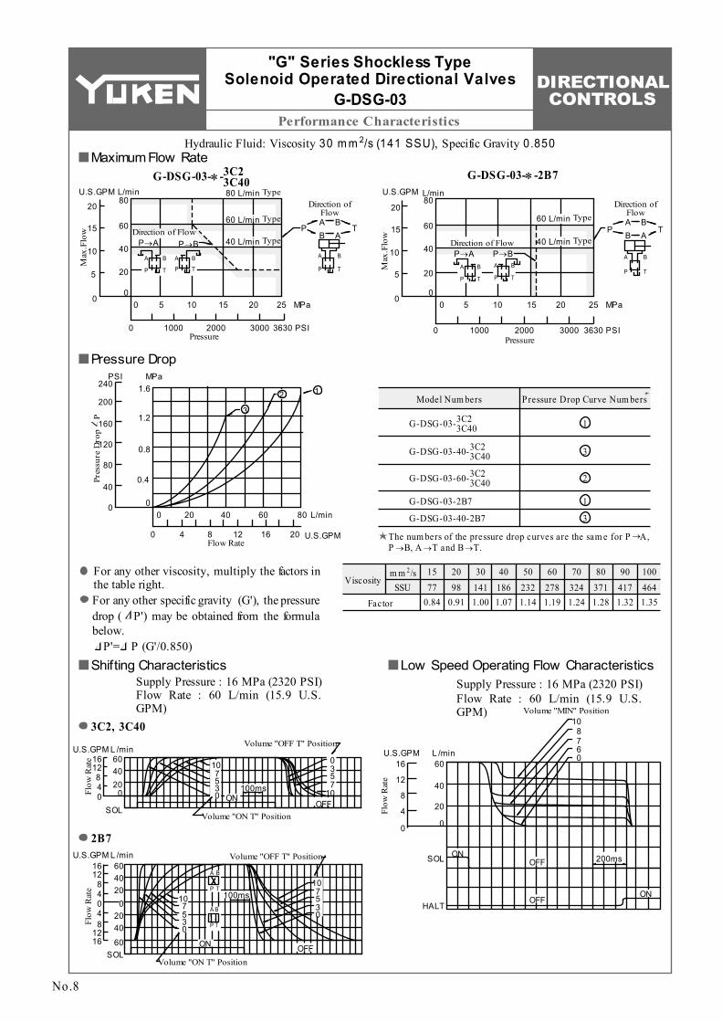
Hydraulic Fluid: Viscosity 2 30 m m /s (141 SSU), Specific Gravity 0.850Maximum Flow Rate
G-DSG-03-∗ 3C2 3C40 - G-DSG-03-∗-2B7
Pressure Drop
For any other viscosity, multiply the factors in the table right.For any other specific gravity (G'), the pressure drop ( P') may be obtained from the formula below.
P'= P (G'/0.850)Shifting Characteristics Low Speed Operating Flow Characteristics
Supply Pressure : 16 MPa (2320 PSI) Flow Rate : 60 L/min (15.9 U.S.GPM)
Supply Pressure : 16 MPa (2320 PSI) Flow Rate : 60 L/min (15.9 U.S.GPM)
2B7
3C2, 3C40
The num bers of the pressure drop curves are the sam e for P A, P B, A T and B T.

DIRECTIONAL CONTROLS
M ounting Surface: ISO 4401-AB-03-4-A
E
Installation Drawings
Model Num bers "C" Thd.G-DSG-01-∗∗∗-∗-50 G-DSG-01-∗∗∗-∗-5090
G 1/2 1/2 NPT
SOL b
SOL a SOL b
40.5 (1.59)
5.5(.22) Dia. Through 9.5(.37) C' bore 4 Places
Pressure Port "P"
110 (4.33)
Solenoid Indicator Light (For Sol. b)
0.75
(.0
3)Tank Port "T"
31
(1.2
2)32
.5
(1.2
8)
Cylinder Port "A"Cylinder Port "B"
Solenoid Indicator Light (For Sol. a)
38
(1.5
0)
263 (10.35)
132 (5.20)
65.5 (2.58)
44.5 (1.75)
0.5 (.02)
11 (.43)
65 (2.56)
Mounting Surface (O-Rings Furnished)
Air Vent (Both Sides) 3 (.12) Hex. Soc.
Electrical Conduit Connection "C" Thd. (Both Ends)
Manual Actuator 6 (.24) Dia.
25
(.98)
89
(3.5
0)
48 (1.89)
109.
5 (4
.31)
197.5 (7.78)
0.5 (.02)
178.5 (7.03)
G-DSG-01-∗-3C2/3C40-∗-50/5090
No.9
"G" Series Shockless Type Solenoid Operated Directional Valves
G-DSG-01
G-DSG-01-∗-2B7-∗-50/5090
Air vent position around valve longitudinal axis can be optionally selected.
For other dim ensions, refer to the drawing above.
DIMENSIONS IN MILLIMETRES (INCHES)

DIRECTIONAL CONTROLS
M ounting Surface: ISO 4401-AC-05-4-A
1. 2.
1
2
Installation Drawings
Model Num bers "C" Thd.G-DSG-03-∗∗∗-∗-50 G-DSG-03-∗∗∗-∗-5090
G 1/2 1/2 NPT
SOL b
SOL aSOL b
G1/
2
G1/2
54 (2.13)
7(.28) Dia. Through 11(.43) Dia. Spotface 4 Places
Pressure Port "P"
141 (5.55)
Solenoid Indicator Light (For Sol. b)
Tank Port "T"
32.5
46
(1.8
1)
Cylinder Port "A"
Cylinder Port "B"
Solenoid Indicator Light (For Sol. a)
35.3
(1
.39)
48 (1.89)
336 (13.23)
39 (1.54)
70 (2.76) Mounting Surface
(O-Rings Furnished)Air Vent (Both Sides) 3 (.12) Hex. Soc.
Electrical Conduit Connection "C" Thd. (Both Ends)
Manual Actuator 6 (.24) Dia.
130.
1 (5
.12)
132 (5.20)
109.
6 (4
.31)
234 (9.21)
50.8 (2.00)
(1.2
8)
27
(1.0
6)
19 (.75)92
(3.62)
102 (4.02)
0.5 (.02)
0.5 (.02)
226.3 (8.91)
G-DSG-03-∗-3C2/3C40-∗-50/5090
"G" Series Shockless Type Solenoid Operated Directional Valves
G-DSG-03
G-DSG-03-∗-2B7-∗-50/5090
For other dim ensions, refer to the drawing above.
No.10
Although the tank port is shown on the left in our sub-plate, either m ay be used. Air vent position around valve longitudinal axis can be optionally selected.
DIMENSIONS IN MILLIMETRES (INCHES)

DIRECTIONAL CONTROLS
E
Installation Drawings
Sub-plate Model Num bers "C" Thd. "D" Thd.
"E" m m (in.)
M5
No.10-24 UNC
M5 No.10-24 UNC
M5
No.10-24 UNC10 (.39) 12 (.47)
10 (.39)
12 (.47)
10 (.39)
12 (.47)
DSGM-01-30 DSGM-01-3080 DSGM-01-3090 DSGM-01X-30 DSGM-01X-3080 DSGM-01X-3090 DSGM-01Y-30 DSGM-01Y-3090
Rc 1/8 1/8 BSP.F 1/8 NPT
Rc 1/4 1/4 BSP.F 1/4 NPT
Rc 3/8 3/8 NPT
Thread Size
A
T
PB
7(.28) Dia. 4 Places
"D" Thd. "E" Deep 4 Places
7(.28) Dia. Through 11(.43) Dia. Spotface
2 Places
14.2(.56)
12.7(.50)
21.5(.85)
30.2(1.19)
40.5(1.59)
7(.28)
71(2.80)
85(3.35)
5.2
(.20)
0.75
(.03)
15.5
(.61)
25.8
(1.0
2)31
(1.2
2)
31.7
5(1
.25)
8.5
(.33)
48(1
.89)
7.5
(.30)
63(2
.48)
15(.59)
16(.63)
32(1.26)
"C" Thd. 4 Places
12.5(.49)
35.5(1.40)
58.5(2.30)
11 (.43)
24 (.94)37
(1.4
6)
DSGM-01∗-30/3080/3090
Sub-plate for "G" Series Shockless Type
Solenoid Operated Directional Valves
No.11
DIMENSIONS IN MILLIMETRES (INCHES)

DIRECTIONAL CONTROLS
Installation Drawings
Sub-plate Model Num bers
DSGM-03-40DSGM-03-2180DSGM-03-2190DSGM-03X-40DSGM-03X-2180DSGM-03X-2190DSGM-03Y-40DSGM-03Y-2180
"C" Thd.Rc 3/8
3/8 BSP.F3/8 NPT
Rc 1/2
Rc 3/4
1/2 BSP.F1/2 NPT
3/4 BSP.F
"D" Thd.
M6
1/4-20 UNC
M6
1/4-20 UNC
M6
1/4-20 UNCDSGM-03Y-2190 3/4 NPT
E
13 (.51)
15 (.59)
F
110 (4.33)
13 (.51)
15 (.59)
13 (.51)
15 (.59)
110 (4.33)
120 (4.72)
H J K L N P Q S T
9 (.35)
9 (.35)
14 (.55)
10 (.39)
10 (.39)
15 (.59)
32 (1.26)
32 (1.26)
50 (1.97)
62 (2.44)
62 (2.44)
80 (3.15)
40 (1.57)
40 (1.57)
45 (1.77)
16 (.63)
16 (.63)
10 (.39)
48 (1.89)
48 (1.89)
47 (1.85)
21 (.83)
21 (.83)
16 (.63)
24 (.94)
24 (.94)
42 (1.65)
Dim ensions m m (Inches)Thread Size
P
BA T
3.2 (.13)
16.7 (.66)
27 (1.06)
37.3 (1.47)
54 (2.13)
90 (3.54)
18 (.71)
J6.
4 (.2
5)
21.4
(.8
4)
32.5
(1
.28)
46
(1.8
1)22
(.8
7)
90
(3.5
4)10
(.3
9)
92 (3.62)
H
F
70
(2.7
6)20
(.7
9)11
0 (4
.33)
T7
(.28)
K L
NP
S
Q76
(2
.99)
11 (.43) Dia. 4 Places
8.8 (.35) Dia. Through 14 (.55) Dia. Spotface 4 Places
"D" Thd. "E" Deep 4 Places
"C" Thd. 4 Places
DSGM-03∗-40/2180/2190
Sub-plate for "G" Series Shockless Type
Solenoid Operated Directional Valves
DIMENSIONS IN MILLIMETRES (INCHES)
No.12

DIRECTIONAL CONTROLS
1. 2.
1 1
2
E
Specifications
X T A P B Y
Electronic Circuit
DescriptionsModel Num bers
G-DSHG-04-3C∗-∗-∗-∗-50/5090 G-DSHG-06-3C∗-∗-∗-∗-50/5090
Max. Flow
Max. Operating Pres.
Max. T-Line Back Pres. MPa (PSI)
MPa (PSI)
L /m in (U.S.GPM)
Voltage
Input Power at 24V
Voltage
Current
Input interface
Electric Power Supply
Shifting signal, low speed operation halt signal (can be used in com m on with electric power supply )
Shifting tim e range (for ON and OFF)
Low speed operation flow rate (m in. flow rate) range (for SOL a and b) L /m in (U.S.GPM)
Low speed operation flow rate (m in. flow rate) hold tim e
Am bient Tem perature
Approx. Mass
160 (42.3)
25 (3630)
16 (2320)
3 (440)
16 (2320)
24 V DC (21 - 28 V DC Included Ripple): Use a stable power supply
36 W 36 W
5 - 48 V DC (Use a stable power supply )
Constant at 10 m A (A constant-current circuit is used)
Sink Ty pe, Source Ty pe
ON: 0.06 - 1.5 s, OFF: 0.1 - 2 s ON: 0.1 - 1 s, OFF: 0.2 - 2 s
5 - 20 (1.3 - 5.3) 10 - 30 (2.6 - 7.9)
Max. 60 s (After 60 seconds, the flow rate decreases gradually .)
0 - 50 °C (32 - 122 °F) with circulated air
250 (66.1)
25 (3630)
16 (2320)
3 (440)
16 (2320)
MPa (PSI)
MPa (PSI)
MPa (PSI)
Max. Drain Line Back Pressure
Max. P ilot Pressure
Min. Required P ilot Pres.
L /m in (U.S.GPM)Pilot Flow at Norm al
at Transition
1.5 (220)
1 (0.3)
4 (1.1)
1 (0.3)
6 (1.6)
12 kg (26.5 lbs.) 15 kg (33.1 lbs.)
Specifications
No.13
The m axim um flow rate is constant irrespective of the working pressure. Be sure that the difference between pilot pressure and drain port back pressure is larger than the m inim um pilot pressure.
Sub-plate MountingG-DSHG-04/06
"G" Series Shockless Type Solenoid Controlled Pilot Operated
Directional Valves

DIRECTIONAL CONTROLS
Model Number Designation / Others
Japanese Standard "JIS" European Design Standard N. Am erican Design Standard
M12 × 60 Lg. 1/2-13 UNC × 2-1/2 Lg.
Socket Head Cap Screw
Valve Model
Num bersSub-plate
Model Num bers
Thread Size
Approx. Mass
kg (lbs.)
Sub-plate Model
Num bersThread
SizeApprox.
Mass kg (lbs.)
Sub-plate Model
Num bersThread
SizeApprox.
Mass kg (lbs.)
G-DSHG-04
G-DSHG-06
DHGM-04-20 DHGM-04X-20DHGM-06-50 DHGM-06X-50
Rc 1/2 Rc 3/4
4.4 4.1
(9.7) (9.0)
Rc 3/4 Rc 1
7.4 7.4
(16.3) (16.3)
DHGM-04-2080 DHGM-04X-2080DHGM-06-5080 DHGM-06X-5080
1/2 BSP.F 3/4 BSP.F
4.4 4.1
(9.7) (9.0)
8.5 8.5
(18.7) (18.7)
3/4 BSP.F 1 BSP.F
DHGM-04-2090 DHGM-04X-2090DHGM-06-5090 DHGM-06X-5090
1/2 NPT 3/4 NPT
4.4 4.1
(9.7) (9.0)
7.4 7.4
(16.3) (16.3)
3/4 NPT 1 NPT
Japanese Standard "JIS" & European Design Standard
Model Num bers N. Am erican Design Standard Qty . Tightening Torque
Nm (in. lbs.)M6 × 45 Lg.
M10 × 50 Lg.1/4-20 UNC × 1-3/4 Lg.
3/8-16 UNC × 2 Lg.G-DSHG-04
G-DSHG-06
2 46
12-15 (106-133) 58-72 (513-637)
100-123 (885-1089)
G-DSHGG Series Shockless Ty pe Solenoid Controlled P ilot Operated Directional Valve, Sub-plate Mounting
G-DSHG -04
Valve Size
04
Series Num ber
:
-50
Design Num ber
∗Design
Standards
Refer to
50
06 50
-3C2
Spool Ty pe
-S
Input Interface
-E
Pilot Connection
-R2
Spool Control Modification (Om it if not required)
No.14
Model Number Designation
Sub-plates are available. Specify the sub-plate m odel num ber from the table above. W hen sub-plates are not used, the m ounting surface should have a good m achined finish.
Attachment (Mtg. Bolts)Socket head cap screws in the table below are included.
Sub-plate
G-DSHG-04/06
"G" Series Shockless Type Solenoid Controlled Pilot Operated
Directional Valves
Design Standards: None 90
Japanese Standard "JIS" and European Design Standard N. Am erican Design Standard
........... ...............
None:Sink Ty pe (Standard)
S:Source Ty pe
3C2
3C40
A B
P Ta b
XY
A B
P Ta b
Y X
None :Internal P ilot
E :External P ilot
R2:W ith Stroke Adjustm ent, Both Ends
RA:W ith Stroke Adjustm ent, Port "A" End
RB:W ith Stroke Adjustm ent, Port "B" End

DIRECTIONAL CONTROLS
E
Performance Characteristics
Viscosity2 m m /s
SSUFactor
15 77
0.84
20 98
0.91
30 141 1.00
40 186 1.07
50 232 1.14
60 278 1.19
70 324 1.24
80 371 1.28
90 417 1.32
100 464 1.35
3C2 3C40 G-DSHG-04-
P→AP→B
A→TB→T
B→T 3C2 3C40 G-DSHG-06-
P→AP→BA→T
0 U.S.GPM
Flow Rate
10 20 30 50 70
0 50 100 150 200 L/min250
40 60
MPa
0
0.4
0.2
0.6
1.2
0.8
1.0
1.4
Pres
sure
Dro
p
P
PSI
200
160
120
80
40
0
250ms
Volume "OFF T" Position
ON
Volume "ON T" Position
1050
05
10
250msVolume "OFF T" Position
05
10105
0
Volume "ON T" Position
500ms
500ms
Volume "MIN" Position Volume "MIN" Position
ON
ON
OFF
OFF
OFF
OFF
0
2010
0
30
50
SOL
HALT
L /minU.S.GPM
Flow
Rat
e
240
200
160
120
80
40
40
60
70
0
SOL
HALT
L/min150
125
100
75
50
2510
0
U.S.GPM
Flow
Rat
e
20
30
40
10
0
U.S.GPM
Flow
Rat
e
20
50
30
40
L /min
0
SOL
200
150
100
50
0
80
60
40
20
100
Flow
Rat
e
L /min
0
SOL
400
300
200
100
U.S.GPM
OFF OFFON
1080
1080
ON
ON
G-DSHG-04 / 06
"G" Series Shockless Type Solenoid Controlled Pilot Operated
Directional Valves
No.15
Hydraulic Fluid: Viscosity 2 30 m m /s (141 SSU), Specific Gravity 0.850Pressure DropG-DSHG-04/06-3C2/3C40
For any other viscosity, multiply the factors in the table below.
For any other specific gravity (G'), the pressure drop ( P') may be obtained from the formula below.
P'= P (G'/0.850)
Shifting CharacteristicsG-DSHG-04-3C2/3C40 G-DSHG-06-3C2/3C40
Low Speed Operating Flow CharacteristicsG-DSHG-04-3C2/3C40 G-DSHG-06-3C2/3C40Supply Pressure : 16 MPa (2320 PSI) Flow Rate : 150 L/min (39.6 U.S.GPM) Pilot Pressure : 16 MPa (2320 PSI)
Supply Pressure : 16 MPa (2320 PSI) Flow Rate : 250 L/min (66.1 U.S.GPM) Pilot Pressure : 16 MPa (2320 PSI)
Supply Pressure : 16 MPa (2320 PSI) Flow Rate : 150 L/min (39.6 U.S.GPM) Pilot Pressure : 16 MPa (2320 PSI)
Supply Pressure : 16 MPa (2320 PSI) Flow Rate : 250 L/min (66.1 U.S.GPM) Pilot Pressure : 16 MPa (2320 PSI)

M ounting Surface: ISO 4401-AD-07-4-A
1. 2.
1
2
DIRECTIONAL CONTROLS
Installation Drawings
Model Num bers "C" Thd.G-DSHG-04-3C∗-∗-∗-50 G-DSHG-04-3C∗-∗-∗-5090
G 1/2 1/2 NPT
L'L
SOL a SOL b
L'L
SOL a SOL b
34 (1.34)
7(.28) Dia. Through 11(.43) Dia. Spotface 4 Places
Pressure Port "P"
Solenoid Indicator Light
Tank Port "T"
34.9 69
.8
(2.7
5)
Cylinder Port "A"
Cylinder Port "B"
Mounting Surface (O-Rings Furnished)
Air Vent (Both Sides) 3 (.12) Hex. Soc. 2 Places Electrical Conduit Connection
"C" Thd. (Both Ends)
50 (1.97)
(1.3
7)11
6 (4
.57)
132 (5.20)
48 (1.89)
11(.43) Dia. Through 17.5(.69) Dia. Spotface 4 Places
Pilot Pressure Port "X" (For External Pilot Models Only)
101.6 (4.00)
79.9 (3.15)
Pilot Drain Port "Y"1.
5 (.0
6)72
.9
(2.8
7)91
(3
.58)
Manual Actuator 6(.24) Dia.
263 (10.35)
65.5 (2.58)
0.5 (.02)
181
(7.1
3)20
0.5
(7.8
9)
50.4 (1.98)
204 (8.03)
3(.12) Dia. Two Locating Pins4 (.1
6)34
(1
.34)
35
(1.3
8)
289(11.38)Fully Extended
93(3.66)Fully Extended
33
(1.3
0)
Stroke Adj. Screw (Port "B" End) 13(.51) Hex.
Lock Nut 17(.67) Hex.
Stroke Adj. Screw (Port "A" End) 13(.51) Hex.
G-DSHG-04-3C∗-∗-∗-50/5090
No.16
Air vent position around valve longitudinal axis can be optionally selected. O-rings for ports: SO-NB-P22 for P /A/B/T ports SO-NB-P9 for X/Y ports
G-DSHG-04
"G" Series Shockless Type Solenoid Controlled Pilot Operated
Directional Valves
G-DSHG-04-3C∗-∗-R∗-∗-50/5090Models with Stroke Adjustment (Option)
DIMENSIONS IN MILLIMETRES (INCHES)

M ounting Surface: ISO 4401-AE-08-4-A
1. 2.
1
2
DIRECTIONAL CONTROLS
E
Installation Drawings
Model Num bers "C" Thd.G-DSHG-06-3C∗-∗-∗-50 G-DSHG-06-3C∗-∗-∗-5090
G 1/2 1/2 NPT
SOL a SOL b
L'L
SOL a SOL b
L'L
53.2 (2.09)
Solenoid Indicator Light
Tank Port "T"
46.1
(1
.81)
Cylinder Port "A"
Cylinder Port "B"
Mounting Surface (O-Rings Furnished)
Air Vent (Both Sides) 3 (.12) Hex. Soc. 2 Places
Electrical Conduit Connection "C" Thd. (Both Ends)
77 (3.03)
137
(5.3
9)
132 (5.20)
48 (1.89)
13.5(.53) Dia. Through 20(.79) Dia. Spotface 6 Places
Pilot Pressure Port "X" (For External Pilot Models Only)
130.2 (5.13)
Pilot Drain Port "Y"
13
(.51)
Manual Actuator 6(.24) Dia.
263 (10.35)
65.5 (2.58)
0.5 (.02)
202
(7.9
5)22
1.5
(8.7
2)
78.5 (3.09) 6(.24) Dia. Two Locating Pins6
(.24)
41
(1.6
1)
134.8(5.31)Fully Extended
40
(1.5
7)
Stroke Adj. Screw (Port "B" End) 13(.51) Hex.
Lock Nut 17(.67) Hex.
Stroke Adj. Screw (Port "A" End) 13(.51) Hex.
Pressure Port "P"
50.5 (1.99)
255 (10.04)
156 (6.14)
92.1
(3
.63)
118
(4.6
5)
376(14.80)Fully Extended
G-DSHG-06-3C∗-∗-∗-50/5090
Air vent position around valve longitudinal axis can be optionally selected. O-rings for ports: SO-NB-P30 for P /A/B/T ports SO-NB-P14 for X/Y ports
G-DSHG-06
"G" Series Shockless Type Solenoid Controlled Pilot Operated
Directional Valves
G-DSHG-06-3C∗-∗-R∗-∗-50/5090Models with Stroke Adjustment (Option)
No.17
DIMENSIONS IN MILLIMETRES (INCHES)

DIRECTIONAL CONTROLS
Installation Drawings
Sub-plate Model Num bers
DHGM-04-20 DHGM-04X-20
"C" Thd.
Rc 1/2 Rc 3/4
"E" Thd.
M10
3/8-16 UNC
1/2 BSP.F 3/4 BSP.F1/2 NPT 3/4 NPT
"D" Thd.
Rc 1/4
1/4 BSP.F
1/4 NPT
"F" Thd.
M6
1/4-20 UNC
DHGM-04-2080 DHGM-04X-2080DHGM-04-2090 DHGM-04X-2090
PTA B
XY
190 (7.48)166
(6.54)101.6 (4.00)
76.7 (3.02)
12(.47)
32.2(1.27)
50 (1.97)
34(1.34)
18.3(.72)
11(.43) Dia. Through 17.5(.69) Dia. Spotface 4 Places
3.6(.14) Dia. 5(.20) Deep 2 Places
14.2 (.56)
65.8 (2.59)
88.1 (3.47)
130 (5.12)
"E" Thd. 17(.67) Deep 4 Places
6(.24) Dia. 2 Places
17.5(.69) Dia. 4 Places
"F" Thd. 12(.47) Deep 2 Places
120
(4.7
2)96
(3
.78)
71.4
(2
.81)
12
(.47)
13.1
(.5
2)69
.8
(2.7
5)55
.6
(2.1
9)14
.2
(.56)
1.6(
.06)
16
(.63)
10.1
(.4
0)57
.1
(2.2
5)90
(3
.54)
36 (1.42)
20 (.79)19
(.75)
P
T
AB
X
Y
Refer to
"D" Thd. 2 Places
125 (4.92)
90 (3.54)
46 (1.81)
65
(2.5
6)29
(1
.14)
58 (2.28)
102 (4.02)
137.5 (5.41)
76
(2.9
9)
21.5
(.85)
33(1
.30)
"C" Thd. 4 Places
No.18
DHGM- -20/2080/209004 04X
Used only on external pilot ty pe valves. To be plugged on internal pilot ty pe valves.
Sub-plate for "G" Series Shockless Type
Solenoid Controlled Pilot Operated Directional Valves
DIMENSIONS IN MILLIMETRES (INCHES)

DIRECTIONAL CONTROLS
E
Installation Drawings
F m m (in.)
Sub-plate Model Num bers "C" Thd. "E" Thd.
M12
1/2-13 UNC
Rc 3/4 Rc 1
3/4 NPT 1 NPT
"D" Thd.
Rc 1/4
1/4 NPT
24 (.94)
26 (1.02)
DHGM-06-50 DHGM-06X-50DHGM-06-5090 DHGM-06X-5090
Sub-plate Model Num bers "C" Thd.
3/4 BSP.F 1 BSP.F
DHGM-06-5080 DHGM-06X-5080
Dim ensions m m (Inches)D E F H J K L N
151.2 (5.95) 155.2 (6.11)
137.7 (5.42) 148 (5.83)
102 (4.02) 106 (4.17)
54.4 (2.14) 50 (1.97)
30.6 (1.20) 25 (.98)
125.8 (4.95) 130 (5.12)
78.2 (3.08) 74 (2.91)
42.5 (1.67) 32 (1.26)
204 (8.03)
12 (.47)
"E" Thd. "F" Deep 6 Places
116
(4.5
7)
17.5
(.69)
53.2 (2.09)
29.4(1.16)
PT
A B
Y
XV
Used only on external pilot type valves. To be plugged on internal pilot type valves.
Not used (plug is not required)
7(.28) Dia. 8(.31) Deep 2 Places
11(.43) Dia. Through 17.5(.69) Dia. Spotface 4 Places
23(.91) Dia. "C" Thd. (From Rear) 4 Places
11(.43) Dia. "D" Thd. (From Rear) 4 Places
180 (7.09)
25 (.98)
130.2 (5.13)
112.7 (4.44)
94.5 (3.72)77
(3.03)
5.6(.22)
19.1
(.75)
92.1
(3
.63)
74.6
(2
.94)
12
(.47)
46.1
(1
.81) 73
.1
(2.8
8)
96.9
(3
.81)
17.5 (.69)
29.5 (1.16)
100.8 (3.97)
126.2 (4.97)
12.5 (.49)
156 (6.14)
50 (1.97)
34(1.34)
35(1.38)
PT
A B
Y
XV
W
204 (8.03)180
(7.09)12
(.47)25
(.98)130.2 (5.13)
M12 Thd. 24(.94) Deep 6 Places
11(.43) Dia. 4 Places
24.5(.96) Dia. 4 Places
12.5 (.49)
156 (6.14)
92.1
(3
.63)
110
(4.3
3)
134
(5.2
8)
8.9
(.35)
12
(.47)
11.9
(.4
7) 116
(4.5
7)
50 (1.97)
35 (1.38)
P T
AB
YW
D
E
FH
J
N
L
K
82
(3.2
3)26
.4
(1.0
4)
28
(1.1
0)
83.5
(3
.29)
55
(2.1
7)
Used only on external pilot type valves. To be plugged on internal pilot type valves.
1/4 BSP.F Thd. 4 Places
"C" Thd. 4 Places
Not used (plug is not required)
Not used (plug is not required)
W
Not used (plug is not required)
V
X
DHGM- -50/509006 06X
No.19
DHGM- -508006 06X
For other dimensions, refer to "DHGM-06∗-50/5090" above.
Sub-plate for "G" Series Shockless Type
Solenoid Controlled Pilot Operated Directional Valves
DIMENSIONS IN MILLIMETRES (INCHES)


![USTA TrafficAnalysisBriefing V7 0 20150530 FINAL[1] · PDF file1."Executive"Summary" ... In2014thethreemajorGulfcarriers" –"Emirates,"Qatar"Airways"and"Etihad" Airways"–"carried"some"4.3"million"passengers"intoandout"of"the](https://img.pdfslide.net/doc/110x75/5aa125967f8b9a46238b5bf2/usta-trafficanalysisbriefing-v7-0-20150530-final1-in2014thethreemajorgulfcarriers.jpg)