Embed Size (px)
Citation preview
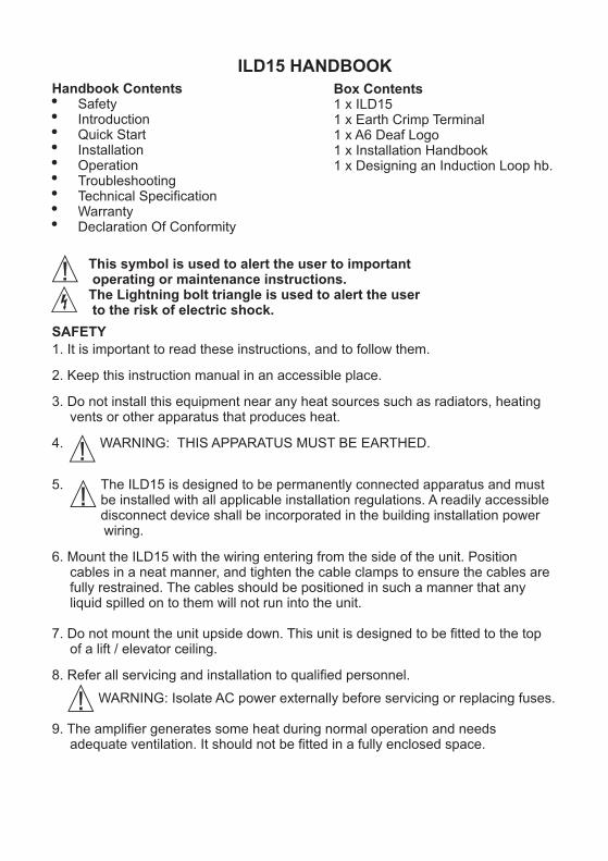
ILD15 HANDBOOKBox Contents1 x ILD151 x Earth Crimp Terminal1 x A6 Deaf Logo1 x Installation Handbook1 x Designing an Induction Loop hb.
Handbook Contents!
! Introduction! Quick Start! Installation! Operation! Troubleshooting! Technical Specification! Warranty! Declaration Of Conformity
Safety
This symbol is used to alert the user to important operating or maintenance instructions.The Lightning bolt triangle is used to alert the user to the risk of electric shock.
SAFETY
1. It is important to read these instructions, and to follow them.
2. Keep this instruction manual in an accessible place.
3. Do not install this equipment near any heat sources such as radiators, heating vents or other apparatus that produces heat.
4. WARNING: THIS APPARATUS MUST BE EARTHED.
5. The ILD15 is designed to be permanently connected apparatus and must be installed with all applicable installation regulations. A readily accessible disconnect device shall be incorporated in the building installation power wiring.
6. Mount the ILD15 with the wiring entering from the side of the unit. Position cables in a neat manner, and tighten the cable clamps to ensure the cables are fully restrained. The cables should be positioned in such a manner that any liquid spilled on to them will not run into the unit.
7. Do not mount the unit upside down. This unit is designed to be fitted to the top of a lift / elevator ceiling.
8. Refer all servicing and installation to qualified personnel.
WARNING: Isolate AC power externally before servicing or replacing fuses.
9. The amplifier generates some heat during normal operation and needs adequate ventilation. It should not be fitted in a fully enclosed space.

INTRODUCTION
The ILD15 has been designed as a high quality stand-alone induction loop driver for use in small to medium size lifts, although the rugged construction may be suited to other industrial applications.
The unit is designed to drive a loop constructed out of custom built metal bars, which is a very low impedance. Ordinary wire can sometimes be used if it can be installed inside the lift car, but care must be taken to ensure the loop satisfies the unit’s load requirements.
The ILD15 comes in a number of different versions
All versions have:#two separate audio inputs, #230V or 115V AC power supply (factory set option) #transformer coupled loop output.
The standard unit has one low-Z speaker line level input and one 100V PA line input.
Unit versions are indicated by the suffix:#BB - Battery back-up (If AC power fails, battery powers unit). #NB - No battery back-up. #BBL / NBL - As above, but two line level / low Z speaker inputs (and no 100V
PA line input).
All connections (except the ‘Protective Earth Terminal’) are via vibration-resistant cage clamp terminals which are quick and easy to connect.
QUICK START
1. Fit ILD15 on top of lift where it will not be vulnerable to damage and where the cables will be protected.
2. Fit loop cable / bars (refer to fitting section) Ensure loop is insulated from lift body.
3. Connect loop to amplifier using feed cables. Ensure feed pair is twisted together.
4. Connect Signal Inputs (see input connection drawings) using twisted pair cable.
5. Connect AC power (see points 5 and 8 in Safety section)
6. Turn ‘Gain 1’, ‘Gain 2’, and ‘Drive’ controls fully anticlockwise (minimum), and the ‘loss’ control to centre setting.
7. Switch on external power:-!
(Not ‘NB’ or ‘NBL’ version)
8. Operate internal switch SW2 ( not fitted on ‘NB’ or ‘NBL’ version)! Check Green ‘Power’ LED illuminates.
10. Apply input signal (eg intercom). Increase the input control until the Green ‘Compression’ LED begins to light.
11. Repeat item10 for the second input (if used). Only apply one audio signal at a time when setting up the system.
12. Adjust the DRIVE control until the Yellow ‘Loop Current’ LED lights at peaks in the input signal. NOTE: Once the DRIVE control is set, do not adjust it again.
Check Yellow ‘Battery Charge’ or Green ‘Battery Float’ LED illuminates.
LOOP
ACPOWER
SW2
INPUT 1
INPUT 2
DRIVE
LOSS
COMPRESSION
LOOP CURRENT
POWER
INPUT 2
INPUT 1
Ins
ert
sc
rew
dri
ve
rto
op
en
co
nta
ct
BATTERY CHARGE BATTERY FLOAT
Push plungerto open contactbefore inserting wire.
Push plungerto open contactbefore inserting wire.
ACPOWER CABLE
AUDIO INPUT
LOOPCABLEC
ab
les
mu
st
be
ke
pt
ins
ep
ara
te b
us
hin
gs
— D
o n
ot
mix
ca
ble
s — AC POWER FUSE
Under insulating barrier
OFF
NORMAL BATTERY FUSE
N
L
E
Layout
Basic Wiring
Audio Input signal
Switched& fused powersource
Loop
Twisted Pair Cable to Loop
ILD15

INTRODUCTION
The ILD15 has been designed as a high quality stand-alone induction loop driver for use in small to medium size lifts, although the rugged construction may be suited to other industrial applications.
The unit is designed to drive a loop constructed out of custom built metal bars, which is a very low impedance. Ordinary wire can sometimes be used if it can be installed inside the lift car, but care must be taken to ensure the loop satisfies the unit’s load requirements.
The ILD15 comes in a number of different versions
All versions have:#two separate audio inputs, #230V or 115V AC power supply (factory set option) #transformer coupled loop output.
The standard unit has one low-Z speaker line level input and one 100V PA line input.
Unit versions are indicated by the suffix:#BB - Battery back-up (If AC power fails, battery powers unit). #NB - No battery back-up. #BBL / NBL - As above, but two line level / low Z speaker inputs (and no 100V
PA line input).
All connections (except the ‘Protective Earth Terminal’) are via vibration-resistant cage clamp terminals which are quick and easy to connect.
QUICK START
1. Fit ILD15 on top of lift where it will not be vulnerable to damage and where the cables will be protected.
2. Fit loop cable / bars (refer to fitting section) Ensure loop is insulated from lift body.
3. Connect loop to amplifier using feed cables. Ensure feed pair is twisted together.
4. Connect Signal Inputs (see input connection drawings) using twisted pair cable.
5. Connect AC power (see points 5 and 8 in Safety section)
6. Turn ‘Gain 1’, ‘Gain 2’, and ‘Drive’ controls fully anticlockwise (minimum), and the ‘loss’ control to centre setting.
7. Switch on external power:-!
(Not ‘NB’ or ‘NBL’ version)
8. Operate internal switch SW2 ( not fitted on ‘NB’ or ‘NBL’ version)! Check Green ‘Power’ LED illuminates.
10. Apply input signal (eg intercom). Increase the input control until the Green ‘Compression’ LED begins to light.
11. Repeat item10 for the second input (if used). Only apply one audio signal at a time when setting up the system.
12. Adjust the DRIVE control until the Yellow ‘Loop Current’ LED lights at peaks in the input signal. NOTE: Once the DRIVE control is set, do not adjust it again.
Check Yellow ‘Battery Charge’ or Green ‘Battery Float’ LED illuminates.
LOOP
ACPOWER
SW2
INPUT 1
INPUT 2
DRIVE
LOSS
COMPRESSION
LOOP CURRENT
POWER
INPUT 2
INPUT 1
Ins
ert
sc
rew
dri
ve
rto
op
en
co
nta
ct
BATTERY CHARGE BATTERY FLOAT
Push plungerto open contactbefore inserting wire.
Push plungerto open contactbefore inserting wire.
ACPOWER CABLE
AUDIO INPUT
LOOPCABLEC
ab
les
mu
st
be
ke
pt
ins
ep
ara
te b
us
hin
gs
— D
o n
ot
mix
ca
ble
s — AC POWER FUSEUnder insulating barrier
OFF
NORMAL BATTERY FUSE
N
L
E
Layout
Basic Wiring
Audio Input signal
Switched& fused powersource
Loop
Twisted Pair Cable to Loop
ILD15

INSTALLATION
ToolsYou will require the following:! Phillips screwdriver ! Small flat blade screwdriver ! Ratchet crimp tool
LocationThe amplifier should be mounted where :
! it is protected from drips or sprays of water! it is not vulnerable to mechanical damage! the controls can be accessed through the open cover.
The unit must be close to the loop; when used on a lift, it is typically mounted on top of the lift car.
Cable glandsThe ILD15 is supplied with three cable glands to firmly clamp the cables entering the unit. The AC power, audio inputs & loop output cables should be fed through the case separately as shown in ‘Basic Wiring’. The unit is designed to provide protection to IP43. This is subject to round wires between 5 and 10mm diameter being used. Suitable sleeving should be fitted to twisted pair or smaller cables to enlarge them to within this range.
To further prevent ingress run cables along the mounting surface then up into the cable glands
Connections
GENERAL: Open the cage clamp terminals using a flat bladed screwdriver. See ‘Layout’ drawing for location of each terminal and details of its operation.
LOOP: Connect the loop cable ends to the loop output connector. make sure that the feed cable (the 2-wire section between the amplifier and loop) is tightly twisted together and less than 3m in length. In lifts, the loop connecting wires
2should not be less than 2.5mm (AWG 12) area. See below for loop design
INPUTS: Connect inputs as shown in the diagram. Note that input 2 is different on the ILD15BB and BBL. Use Low-Z connection for Intercom Speakers, Voice Announcers, etc, and 100V line for building PA.
For all inputs, use twisted pair cables, preferably with screen.AC POWER: The ILD15 can be supplied in 115VAC or 230VAC versions. Check that the version you have is compatible with your power supply.
Isolate external AC power source before working on power connections Use the crimp terminal, washer & nut provided to connect incoming AC Earth
OPERATION (see ‘Layout’ drawing for control names & positions)
1. Turn ‘Gain 1’, ‘Gain 2’ and ‘Drive’ controls fully anti-clockwise. Set ‘MLC’ control to mid-position.
2. Switch on external AC power ! Check ‘Battery Charge’ or ‘Battery Float’ LED illuminates. (Not ‘NB’ version)
3. Set internal switch SW2 to ‘Normal’ (Not fitted on ‘NB’ version) ! Check Green ‘Power’ LED illuminates.
4. Apply an audio signal to one input (e.g. speech through an intercom). Turn the associated Gain control clockwise until Green ‘Compression’ LED illuminates.
Mo n ing De ai su t t l
160mm
40m
m2
TopView
Block Diagram Compression LED Output Current LED
Output
MLC Adjust
Drive
Loopoutput
115V230VSelect
Fuse
Power LED
Powerinput
Input 1
Input 2
AC Input Version
MLC AGC
Batterycharger
DC power tosystem
Charge Float
Twist together
Low Z Speaker feed
InputsBB & NB Versions
100V speaker line
Input 2
Input 1
ILD15
I/P1
ILD15
I/P2
Twist together
Twist together
Low Z Speaker feed
Low Z Speaker feed
Input 1
Input 2
InputsBBL & NBL Versions
ILD15
I/P1
ILD15
I/P2

INSTALLATION
ToolsYou will require the following:! Phillips screwdriver ! Small flat blade screwdriver ! Ratchet crimp tool
LocationThe amplifier should be mounted where :
! it is protected from drips or sprays of water! it is not vulnerable to mechanical damage! the controls can be accessed through the open cover.
The unit must be close to the loop; when used on a lift, it is typically mounted on top of the lift car.
Cable glandsThe ILD15 is supplied with three cable glands to firmly clamp the cables entering the unit. The AC power, audio inputs & loop output cables should be fed through the case separately as shown in ‘Basic Wiring’. The unit is designed to provide protection to IP43. This is subject to round wires between 5 and 10mm diameter being used. Suitable sleeving should be fitted to twisted pair or smaller cables to enlarge them to within this range.
To further prevent ingress run cables along the mounting surface then up into the cable glands
Connections
GENERAL: Open the cage clamp terminals using a flat bladed screwdriver. See ‘Layout’ drawing for location of each terminal and details of its operation.
LOOP: Connect the loop cable ends to the loop output connector. make sure that the feed cable (the 2-wire section between the amplifier and loop) is tightly twisted together and less than 3m in length. In lifts, the loop connecting wires
2should not be less than 2.5mm (AWG 12) area. See below for loop design
INPUTS: Connect inputs as shown in the diagram. Note that input 2 is different on the ILD15BB and BBL. Use Low-Z connection for Intercom Speakers, Voice Announcers, etc, and 100V line for building PA.
For all inputs, use twisted pair cables, preferably with screen.AC POWER: The ILD15 can be supplied in 115VAC or 230VAC versions. Check that the version you have is compatible with your power supply.
Isolate external AC power source before working on power connections Use the crimp terminal, washer & nut provided to connect incoming AC Earth
OPERATION (see ‘Layout’ drawing for control names & positions)
1. Turn ‘Gain 1’, ‘Gain 2’ and ‘Drive’ controls fully anti-clockwise. Set ‘MLC’ control to mid-position.
2. Switch on external AC power ! Check ‘Battery Charge’ or ‘Battery Float’ LED illuminates. (Not ‘NB’ version)
3. Set internal switch SW2 to ‘Normal’ (Not fitted on ‘NB’ version) ! Check Green ‘Power’ LED illuminates.
4. Apply an audio signal to one input (e.g. speech through an intercom). Turn the associated Gain control clockwise until Green ‘Compression’ LED illuminates.
Mo n i g De a su t n t il
16 mm0
024
mmTop
V ewi
Block Diagram Compression LED Output Current LED
Output
MLC Adjust
Drive
Loopoutput
115V230VSelect
Fuse
Power LED
Powerinput
Input 1
Input 2
AC Input Version
MLC AGC
Batterycharger
DC power tosystem
Charge Float
Twist together
Low Z Speaker feed
InputsBB & NB Versions
100V speaker line
Input 2
Input 1
ILD15
I/P1
ILD15
I/P2
Twist together
Twist together
Low Z Speaker feed
Low Z Speaker feed
Input 1
Input 2
InputsBBL & NBL Versions
ILD15
I/P1
ILD15
I/P2

TROUBLESHOOTING For correct operation , you should have the following
! Either ‘Battery Charge’ or ‘Battery Float’ - if external power on! ‘Power’ (Green)
! ‘Compression’ (Green) only whilst audio signal is applied to an input! ‘Loop Current’ (Yellow) only at peaks of audio signal
LEDs illuminated:(Yellow) (Green)
Power LED not illuminated ! SW2 set to ‘OFF’ - change setting to ‘NORMAL’.! Battery discharged and external AC mains supply off - turn on external AC mains supply to
charge battery and to operate unit.! Battery Fuse Blown - fit a correctly rated replacement (NB turn off AC power and SW2 first)
Battery Charge and Battery Float LEDs not illuminated! External AC mains supply off - turn on external AC mains supply! AC Power Fuse Blown - fit a correctly rated replacement (NB turn off AC power and SW2 first)
! Battery missing/not fitted or not connected - fit battery (of correct type) or reconnect it
Compression LED not illuminated at any time! No inputs connected - connect an input as described above! Relevant ‘Gain’ control not turned up far enough - adjust control as appropriate! Input signal level too low - check that input signal is >78mV rms for Low-Z speaker inputs, or
10V for 100V line input.
Drive LED not illuminated (even at peaks of signal)! Loop not connected or open circuit - See above for correct loop location, and check loop
continuity using a resistance meter. Value should be under 300mW.! Relevant ‘Gain’ control not turned up far enough - adjust control as appropriate
5. Turn the Drive control clockwise until the Loop Current LED lights at peaks in the input signal. Once set, there is no need to adjust the Drive control again.
6. Repeat item 4 for the other input (if used). When adjusting each input, make sure that audio signal(s) are removed from the other inputs. This ensures that all signals are set to equivalent loudness and are operating the compressor correctly.
7. Listen to the audio signal using an induction loop tester or headphone receiver (such as the ILR3) whilst standing in the area covered by the loop. ! Check that adequate volume is received (volume control at mid-position on the ILR3).
Adjust the ‘MLC’ control for best sound quality.-1If you have an audio analyser and calibrated field probe (e.g. CMR3) available, check for 400mAm max field
strength at 1kHz and ±3dB frequency response.
Loop Design The loop installed in the lift car needs to be designed and fitted correctly if the system is to be effective.
Most lifts are built with metal walls and ceilings. Because of the shielding effect of the metal ‘box’ in such lifts, the loop cable needs to be on the INSIDE of the car. This is normally achieved by constructing a special loop from metal bars fixed to, but insulated from, the ceiling. (This can be supplied by Ampetronic).
If the ceiling is not metal, or a suitable hidden location can be found inside a metal lift car, normal insulated wire of 2.5 mm² or 4 mm² can be used.
The connection from the loop to the equipment should be made using two 2.5 mm² wires twisted together.
Please consult Ampetronic if you need more advice about the loop design.
No field received in the loop area ! If ‘Drive’ LED is illuminated at peaks of signal, but no field is received in the loop area, then
the loop is installed in the wrong place or there is a short circuit between the ends of the feed cable. Read the ‘Loop design’ section above to confirm loop design.
! If ‘Drive’ LED is not illuminated, see previous troubleshooting options for a solution.
Power Supply (AC): Loop Design:Nominal Supply Voltage:230V 45-65Hz Depends on application - typically steelFuse: T 100mA L bars on inside of lift, with interconnectionSupply current (Max): 83mA on top of lift car.Supply Current (Quiescent): 70mA Consult Ampetronic for advice.
Loop Output: Nominal Supply Voltage:115V 45-65HzCurrent: >9.0A peak into 0.1WFuse: T 200mA LVoltage: >1.5V peakSupply current (Max): 166mA
Supply Current (Quiescent): 140mA Loop Resistance: up to 0.1W resistive or0.15W max impedance reactive @ 1.6kHz
Live and Neutral connection via vibration Connection via vibration proof cage clamp resistant cage clamp terminals. terminals.This apparatus must be Earthed.
Frequency Response: Use the crimp terminal provided.80Hz - 5.0kHz ± 1.5dB, at low levelmeasured as loop current with no MLC.Inputs:
Transformer isolated (1500Vac minimum) MLC (Metal Loss Correction):floating input. 0 dB to 4dB / Octave boost. Connection via vibration proof cage clamp Fully anticlockwise - flat response.terminals.
Battery back up (BB / BBL versions):Line level / Low-Z speaker input: Internal 12V, 2.1Ah lead acid battery with
appropriate charging circuits. Input Impedance: 4kWSensitivity: -20dBu (78mVrms) for full output Battery power sufficient for 12 hours Overload:>+19dBu (6.8Vrms) standby +0.5 hours full operation.
Battery Fuse: T 1.6A L100v Line input: (BB / NB versions)
Environmental:Input Impedance:120kW Ambient temperature: -1Sensitivity:+22dBu (10Vrms) for full output
Overload:>+47dBu (170Vrms)
Compression (AGC): Physical:40dB dynamic rangeCompression controlled by adjusting inputlevel. Attack and decay time constants optimizedfor speech.
Standards:Meets relevant CE, EMC and safetystandards.IEC 60118-4 AFILS
Please contact Ampetronic if you need further assistance.
0°C to + 40°CIP rating: IP43 when correctly installed.Refer to installation section for details.
Weight: 3.8kgLength: 255mmWidth: 190mmHeight: 90mm
TECHNICAL SPECIFICATIONS

This product carries a five year parts and labour warranty which could be invalidated if these instructions are not followed correctly, or if the unit is misused in any way.
The five year warranty is dated from the time the equipment leaves Ampetronic and NOT when it is installed.
Note: Battery is only covered by a 1 year warranty.
Manufacturer: Ampetronic Ltd.,Northern Road,Newark,Nottinghamshire.NG24 2ETUnited Kingdom.
Declares that the product:Description: Induction Loop DriverType name: ILD15BB / NB / BBL
Conforms to the following Directive(s) and Norm(s):Directive 2004/108/ECEMC: EN55103-1 : 1997 Emission
EN55103-2 : 1997 Immunity Directive 2006/95/ECSafety: EN60065: 2002
Date Jan 2009Leon PietersTechnical Director,Ampetronic Ltd.
WARRANTY
DECLARATION OF CONFORMITY
UP12602-6