Embed Size (px)
Citation preview
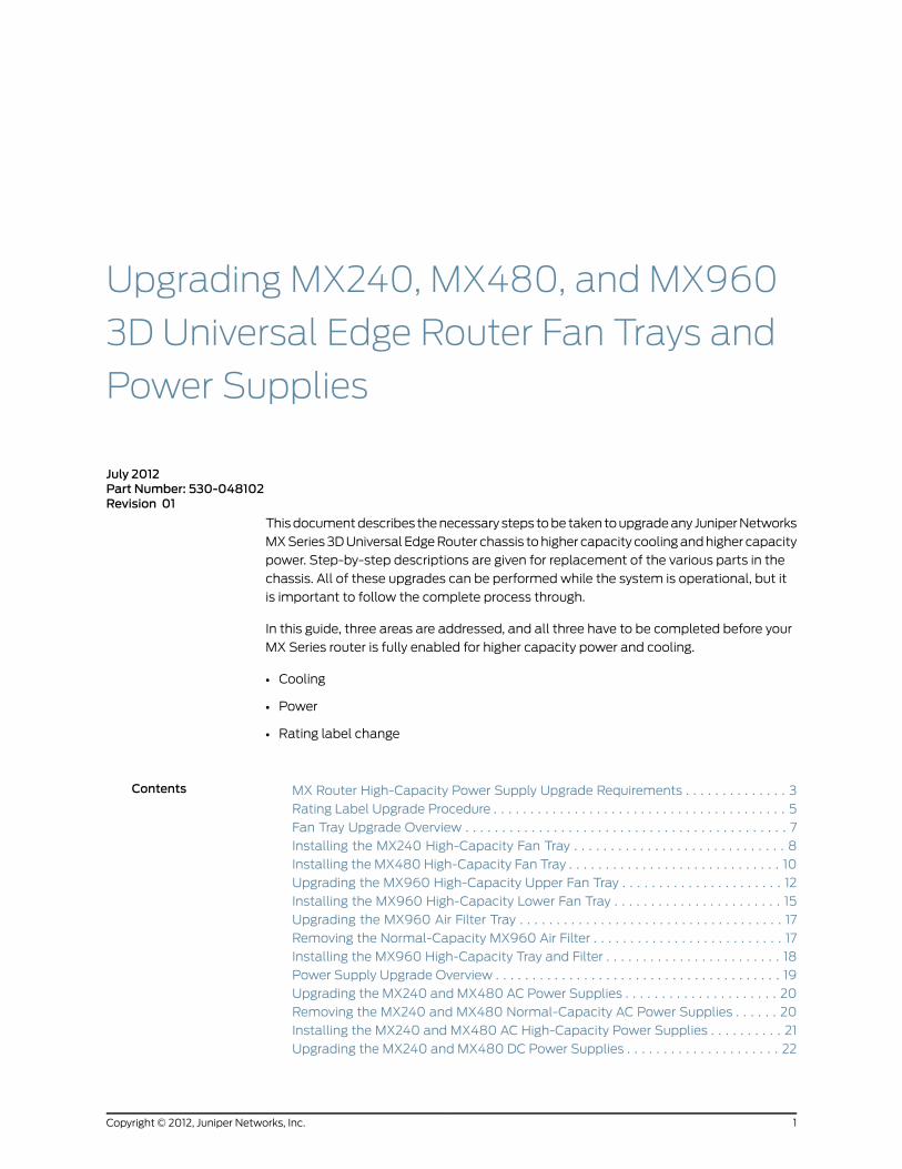
Upgrading MX240, MX480, and MX960
3D Universal Edge Router Fan Trays and
Power Supplies
July 2012Part Number: 530-048102Revision 01
Thisdocumentdescribes thenecessary steps tobe taken toupgradeany JuniperNetworks
MXSeries3DUniversal EdgeRouter chassis tohigher capacity coolingandhigher capacity
power. Step-by-step descriptions are given for replacement of the various parts in the
chassis. All of these upgrades can be performed while the system is operational, but it
is important to follow the complete process through.
In this guide, three areas are addressed, and all three have to be completed before your
MX Series router is fully enabled for higher capacity power and cooling.
• Cooling
• Power
• Rating label change
Contents MX Router High-Capacity Power Supply Upgrade Requirements . . . . . . . . . . . . . . 3
Rating Label Upgrade Procedure . . . . . . . . . . . . . . . . . . . . . . . . . . . . . . . . . . . . . . . . 5
Fan Tray Upgrade Overview . . . . . . . . . . . . . . . . . . . . . . . . . . . . . . . . . . . . . . . . . . . . 7
Installing the MX240 High-Capacity Fan Tray . . . . . . . . . . . . . . . . . . . . . . . . . . . . . 8
Installing the MX480 High-Capacity Fan Tray . . . . . . . . . . . . . . . . . . . . . . . . . . . . . 10
Upgrading the MX960 High-Capacity Upper Fan Tray . . . . . . . . . . . . . . . . . . . . . . 12
Installing the MX960 High-Capacity Lower Fan Tray . . . . . . . . . . . . . . . . . . . . . . . 15
Upgrading the MX960 Air Filter Tray . . . . . . . . . . . . . . . . . . . . . . . . . . . . . . . . . . . . 17
Removing the Normal-Capacity MX960 Air Filter . . . . . . . . . . . . . . . . . . . . . . . . . . 17
Installing the MX960 High-Capacity Tray and Filter . . . . . . . . . . . . . . . . . . . . . . . . 18
Power Supply Upgrade Overview . . . . . . . . . . . . . . . . . . . . . . . . . . . . . . . . . . . . . . . 19
Upgrading the MX240 and MX480 AC Power Supplies . . . . . . . . . . . . . . . . . . . . . 20
Removing the MX240 and MX480 Normal-Capacity AC Power Supplies . . . . . . 20
Installing the MX240 and MX480 AC High-Capacity Power Supplies . . . . . . . . . . 21
Upgrading the MX240 and MX480 DC Power Supplies . . . . . . . . . . . . . . . . . . . . . 22
1Copyright © 2012, Juniper Networks, Inc.
Removing the MX240 and MX480 Normal-Capacity DC Power Supplies . . . . . . 22
Installing the MX240 and MX480 DC High-Capacity Power Supplies . . . . . . . . . 24
Upgrading the MX960 AC Power Supplies . . . . . . . . . . . . . . . . . . . . . . . . . . . . . . . 27
Removing the MX960 Normal-Capacity AC Power Supplies . . . . . . . . . . . . . . . . 28
Installing the MX960 AC High-Capacity Power Supplies . . . . . . . . . . . . . . . . . . . 30
Upgrading the MX960 DC Power Supplies Overview . . . . . . . . . . . . . . . . . . . . . . . 33
Removing a Normal-Capacity MX960 DC Power Supply . . . . . . . . . . . . . . . . . . . 33
Installing the MX960 DC High-Capacity Power Supplies . . . . . . . . . . . . . . . . . . . 35
Upgrading from Single-feed to Dual-feed Configuration on a MX960 AC
High-Capacity Power Supply . . . . . . . . . . . . . . . . . . . . . . . . . . . . . . . . . . . . . . 39
Upgrading from Single-Feed to Dual-Feed Configuration on an MX960 DC
High-Capacity Power Supply . . . . . . . . . . . . . . . . . . . . . . . . . . . . . . . . . . . . . . 40
Changing the MX240 and MX480 DC High-Capacity Power Supply Input Mode
Switch . . . . . . . . . . . . . . . . . . . . . . . . . . . . . . . . . . . . . . . . . . . . . . . . . . . . . . . . 43
JUNOS Documentation and Release Notes . . . . . . . . . . . . . . . . . . . . . . . . . . . . . . 43
Requesting Technical Support . . . . . . . . . . . . . . . . . . . . . . . . . . . . . . . . . . . . . . . . 44
Self-Help Online Tools and Resources . . . . . . . . . . . . . . . . . . . . . . . . . . . . . . 44
Opening a Case with JTAC . . . . . . . . . . . . . . . . . . . . . . . . . . . . . . . . . . . . . . . . 44
Revision History . . . . . . . . . . . . . . . . . . . . . . . . . . . . . . . . . . . . . . . . . . . . . . . . . . . . 45
Copyright © 2012, Juniper Networks, Inc.2
Upgrading MX240, MX480, and MX960 3D Universal Edge Router Power Supplies and Fan Trays

MXRouter High-Capacity Power Supply Upgrade Requirements
In order to upgrade the MX router to high-capacity power supplies, there are several
prerequisites before you can perform the upgrade.
• Rating label upgrade
The rating label upgrade ensures that the chassis rating is in line with the optional
higher capacity power supplies that may be installed in your MX Series router.
• Junos OS version
Before upgrading, the MX Series router must be running the Junos OS release listed in
Table 1 on page 3. Note that there are minimum software revision requirements for
the cooling and power supplies. Without this minimum software revision, these new
parts are not supported and likely not detected andmanaged properly.
Table 1: MinimumRequired Junos OS Release
MinimumRequired Junos OS ReleaseComponent
10.0 R1MX240 and MX480 high-capacity fan trays
MX960 high-capacity fan trays
10.0 R2MX240 AC high-capacity power supplies
MX240 DC high-capacity power supplies
MX480 AC high-capacity power supplies
MX480 DC high-capacity power supplies
MX960 AC high-capacity power supplies
10.2 R1MX960 DC high-capacity power supplies
• Additional power feeds required for MX960 DC and MX960 AC power supplies
Additional power feeds are required before you begin the upgrade process for MX960.
MX960 high-capacity DC and AC power supplies require two feeds per power supply
to operate at full power. Fully redundant power supply configuration requires eight
feeds, up from four feeds. The power supplies also operate in a one feedmode which
provide lower output power. In thismode, noadditional feedsare required. Thenumber
of power feeds for MX240 and MX480 high-capacity power supplies is unchanged.
• High-capacity fan trays (MX240andMX480)andhigh-capacity air filter tray (MX960)
TheMXSeries high-capacity fan trays satisfy cooling requirements ofMPCs, andmust
be upgraded for proper cooling. Additionally, for the MX960 router, you must upgrade
both fan trays and the filter tray.
3Copyright © 2012, Juniper Networks, Inc.
MX Router High-Capacity Power Supply Upgrade Requirements

• Additional clearance to accommodate the depth of the MX960 high-capacity power
supplies
Additional clearance is required toaccommodate thedepthof theMX960high-capacity
power supplies; they extend beyond the chassis as shown in Table 2 on page 4. Figure
1 on page 4 and Figure 2 on page 5 shows the chassis dimensions with both the
standard and extended cable managers installed.
Table 2: Clearance Requirements for High-Capacity Power Supplies
Additional depth requirementPower Supply
2.85 in. (7.24 cm)MX960 high-capacity AC powersupply
5.05 in. (12.83 cm)MX960 high-capacity DC powersupply
Figure 1:ChassisDimensionsandClearanceRequirements for theMX960Router with High-Capacity DC Power Supplies
g006
059
Rear of chassisFront of chassis
17.4"(44.2 cm)
23.0"(58.4 cm)
Front-mounting flange
19.2"(48.7 cm)
30" (76.2 cm)clearance recommended
30" (76.2 cm)clearance recommended
for maintenance
Standard cable manager
Extended cable manager
32.85”(83.4 cm)
Total depth withstandard cable manager
Copyright © 2012, Juniper Networks, Inc.4
Upgrading MX240, MX480, and MX960 3D Universal Edge Router Power Supplies and Fan Trays

Figure2:ChassisDimensionsandClearanceRequirements for theMX960Router with High-Capacity AC Power Supplies
g006
065
Rear of chassisFront of chassis
17.4"(44.2 cm)
23.0"(58.4 cm)
Front-mounting flange
19.2"(48.7 cm)
30" (76.2 cm)clearance recommended
30" (76.2 cm)clearance recommended
for maintenance
Standard cable manager
Extended cable manager
30.65”(77.9 cm)
Total depth withstandard cable manager
NOTE: Combinations of normal-capacity and high-capacity power suppliesand fan trays are not supported outside of the upgrade window.
CAUTION: The router cannot be powered from AC and DC power suppliessimultaneously. The first type of power supply detected by the router wheninitially powered on determines the type of power supply allowed by therouter.All installedpower suppliesof theother typearedisabledby the router.If you install a power supply of the other type while the router is operating,the router disables the power supply and generates an alarm.
Rating Label Upgrade Procedure
To attach the agency label:
1. Locate the agency label on the chassis. The labels are located on the side of the
chassis as illustrated in Figure 3 on page 6, Figure 4 on page 6, and Figure 5 on
page 7.
2. Remove the protective backing from the new label and apply it over the current label
on the chassis.
5Copyright © 2012, Juniper Networks, Inc.
Rating Label Upgrade Procedure

Figure 3: MX240 Rating Label
Figure 4: MX480 Rating Label
Copyright © 2012, Juniper Networks, Inc.6
Upgrading MX240, MX480, and MX960 3D Universal Edge Router Power Supplies and Fan Trays

Figure 5: MX960 Rating Label
Fan Tray Upgrade Overview
To upgrade the fan trays, use the procedures in the following sections.
NOTE: Before upgrading the fan tray, make sure the MX Series router isrunning Junos OS Release 10.0 R1 or later to support high-capacity fan trays.
NOTE: To prevent overheating, install the replacement fan tray within twominutes of removing the normal-capacity fan tray.
Figure 6: MX960High-Capacity Fan Tray
g004
707
7Copyright © 2012, Juniper Networks, Inc.
Fan Tray Upgrade Overview

Figure 7: MX480High-Capacity Fan Tray
Figure 8: MX240High-Capacity Fan Tray
Installing theMX240High-Capacity Fan Tray
To remove the fan tray (see Figure 9 on page 9):
1. Loosen the captive screws on the fan tray faceplate.
2. Grasp the fan tray handle and pull it out approximately 1 to 3 inches.
NOTE: The illustration below shows the direction of the fan tray forremoval. Pull the fan tray out 1 to 3 inches initially, grasp it, then removeit completely from the chassis.
Copyright © 2012, Juniper Networks, Inc.8
Upgrading MX240, MX480, and MX960 3D Universal Edge Router Power Supplies and Fan Trays

3. Press the latch located on the inside of the fan tray to release it from the chassis.
4. Place one hand under the fan tray to support it and pull the fan tray completely out
of the chassis as shown in Figure 9 on page 9.
WARNING: To avoid injury, keep tools and your fingers away from the fansas you slide the fan tray out of the chassis. The fansmight still be spinning.
NOTE: To prevent overheating, install the replacement fan tray within twominutes of removing the normal-capacity fan tray.
Figure 9: Removing the Fan Tray
To install the fan tray (see Figure 10 on page 10):
1. Attachanelectrostaticdischarge (ESD)groundingstrap toyourbarewrist, andconnect
the strap to one of the ESD points on the chassis.
2. Grasp the fan tray on each side and insert it straight into the chassis. Note the correct
orientation by the "this side up" label on the top surface of the fan tray.
3. Tighten the captive screws on the fan tray faceplate to secure it in the chassis.
9Copyright © 2012, Juniper Networks, Inc.
Installing the MX240 High-Capacity Fan Tray
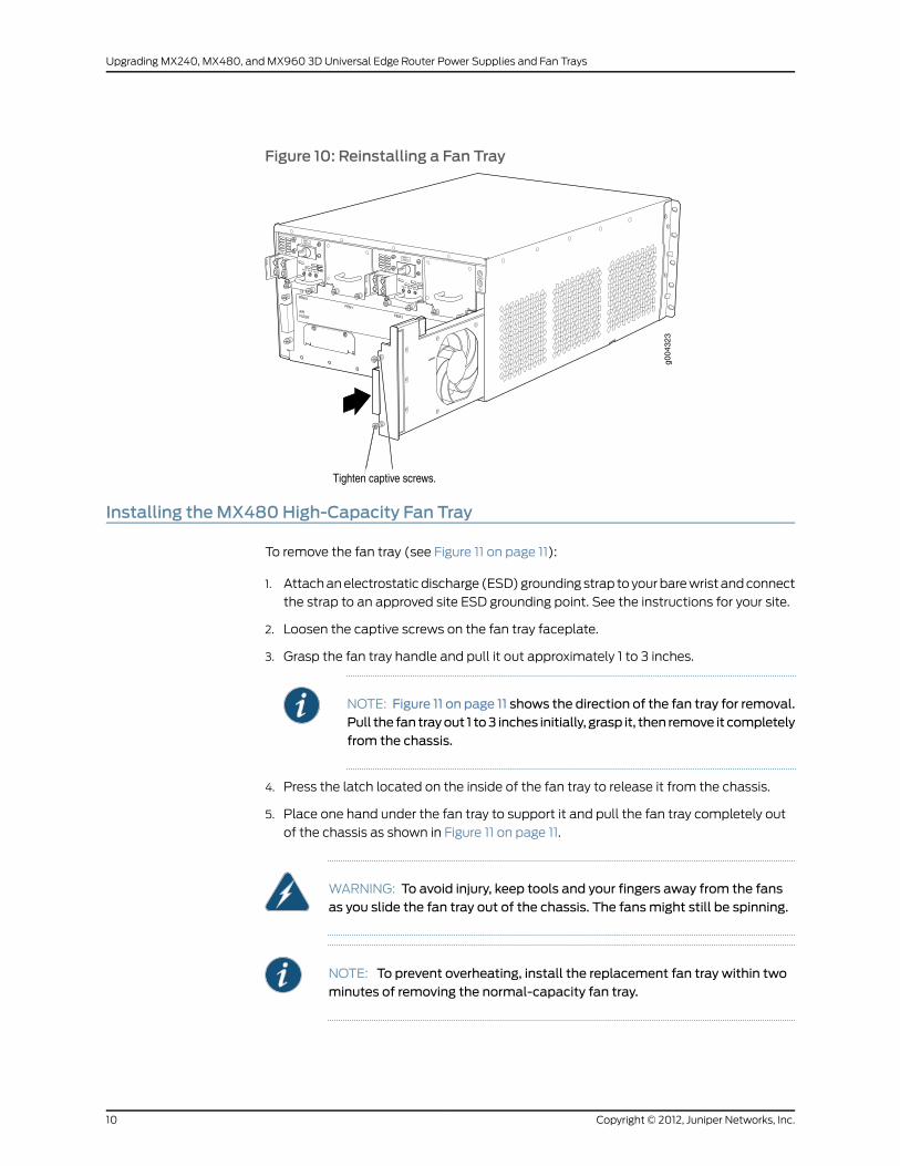
Figure 10: Reinstalling a Fan Tray
Installing theMX480High-Capacity Fan Tray
To remove the fan tray (see Figure 11 on page 11):
1. Attachanelectrostaticdischarge (ESD)groundingstrap toyourbarewrist andconnect
the strap to an approved site ESD grounding point. See the instructions for your site.
2. Loosen the captive screws on the fan tray faceplate.
3. Grasp the fan tray handle and pull it out approximately 1 to 3 inches.
NOTE: Figure 11 on page 11 shows the direction of the fan tray for removal.Pull the fan trayout 1 to3 inches initially, grasp it, then remove it completelyfrom the chassis.
4. Press the latch located on the inside of the fan tray to release it from the chassis.
5. Place one hand under the fan tray to support it and pull the fan tray completely out
of the chassis as shown in Figure 11 on page 11.
WARNING: To avoid injury, keep tools and your fingers away from the fansas you slide the fan tray out of the chassis. The fansmight still be spinning.
NOTE: To prevent overheating, install the replacement fan tray within twominutes of removing the normal-capacity fan tray.
Copyright © 2012, Juniper Networks, Inc.10
Upgrading MX240, MX480, and MX960 3D Universal Edge Router Power Supplies and Fan Trays
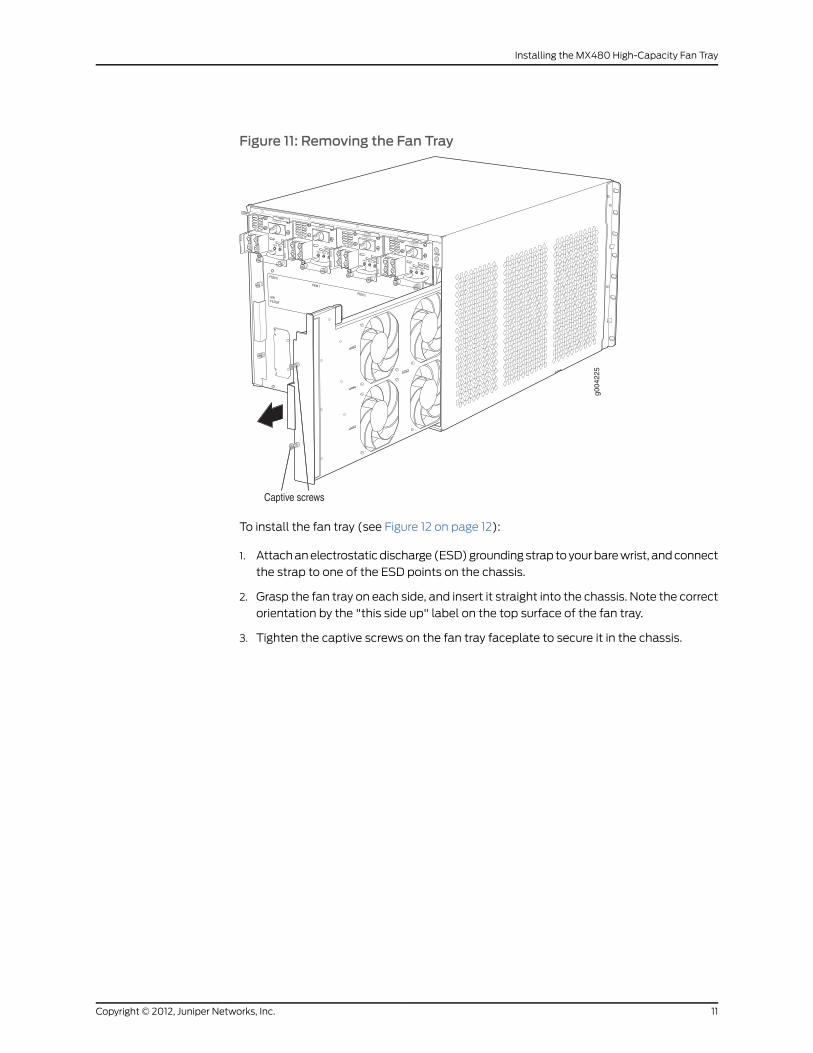
Figure 11: Removing the Fan Tray
To install the fan tray (see Figure 12 on page 12):
1. Attachanelectrostaticdischarge (ESD)groundingstrap toyourbarewrist, andconnect
the strap to one of the ESD points on the chassis.
2. Grasp the fan tray on each side, and insert it straight into the chassis. Note the correct
orientation by the "this side up" label on the top surface of the fan tray.
3. Tighten the captive screws on the fan tray faceplate to secure it in the chassis.
11Copyright © 2012, Juniper Networks, Inc.
Installing the MX480 High-Capacity Fan Tray

Figure 12: Reinstalling a Fan Tray
Upgrading theMX960High-Capacity Upper Fan Tray
It is required that you upgrade both MX960 fan trays as well as the fan filter tray. To
remove thenormal-capacity fan tray and install theMX960high-capacity upper fan tray,
use the following procedures.
NOTE:
To prevent overheating:
• Onefantrayshouldalwaysbe installedandoperationalduring theupgradeprocess.
• Install the replacement fan tray within twominutes of removing thenormal-capacity fan tray.
To remove the upper normal-capacity fan tray:
1. Remove the upper acoustic noise cover if it is installed. Rotate the latch knobs
counterclockwise until the cover is released or until the knobs stop turning.
2. Attachanelectrostaticdischarge (ESD)groundingstrap toyourbarewrist, andconnect
the strap to one of the ESD points on the chassis.
3. Loosen the captive screw on each side of the fan tray faceplate.
Copyright © 2012, Juniper Networks, Inc.12
Upgrading MX240, MX480, and MX960 3D Universal Edge Router Power Supplies and Fan Trays

NOTE: Figure 13onpage 13 shows thedirectionof the fan tray for removal.Pull the fan trayout 1 to3 inches initially, grasp it, then remove it completelyfrom the chassis.
Figure 13: Removing a Normal-Capacity Upper Fan Tray
OK
0
FAIL
ONLINE
OK
1
FAIL
ONLINE
OK
2
FAIL
ONLINE
OK
3
FAIL
ONLINE
OK
4
FAIL
ONLINE
OK
5
FAIL
ONLINE
OK
0
FAIL
ONLINE
MASTERONLINEOFFLINE
RE0
FANPEM
1
0
0 1 2 3
RE1OK
1
FAIL
ONLINE
OK
7
FAIL
ONLINE
OK
8
FAIL
ONLINE
OK
9
FAIL
ONLINE
OK
10
FAIL
ONLINE
OK
11
FAIL
ONLINE
OK
2 6
FAIL
ONLINE
ACO/LT
YELLOW ALARM RED ALARM
NC NOC NC NOC
1 01 0
1 0
1 01 0
1 10 0
1 01 01 0
g004
042
4. Press on the two latches located on the inside of the fan tray to release the fan tray
from the chassis.
5. Place one hand under the fan tray to support it, and pull the fan tray completely out
of the chassis as shown in Figure 13 on page 13.
WARNING: Toavoid injury, keep tools and your fingers away from the fansas youslide the fan trayoutof thechassis. The fansmight still be spinning.
To install the upper high-capacity fan tray, use the following procedure. If the acoustic
noise cover is installed, the upper acoustic cover must be removed.
NOTE: Verify that you are installing the high-capacity fan tray; the tray islabeled “FFAN Tray HCMX960.”
13Copyright © 2012, Juniper Networks, Inc.
Upgrading the MX960 High-Capacity Upper Fan Tray
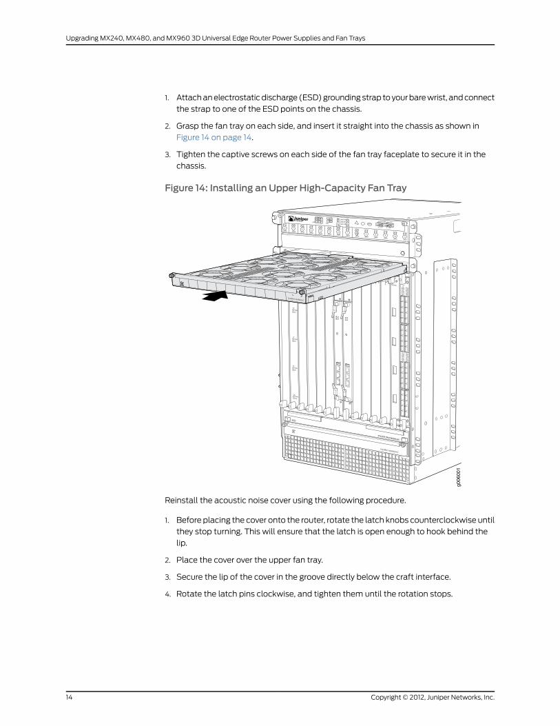
1. Attachanelectrostaticdischarge (ESD)groundingstrap toyourbarewrist, andconnect
the strap to one of the ESD points on the chassis.
2. Grasp the fan tray on each side, and insert it straight into the chassis as shown in
Figure 14 on page 14.
3. Tighten the captive screws on each side of the fan tray faceplate to secure it in the
chassis.
Figure 14: Installing an Upper High-Capacity Fan Tray
g006
001
OK
0
FAIL
ONLINE
OK
1
FAIL
ONLINE
OK
2
FAIL
ONLINE
OK
3
FAIL
ONLINE
OK
4
FAIL
ONLINE
OK
5
FAIL
ONLINE
OK
0
FAIL
ONLINE
MASTERONLINEOFFLINE
RE0
FANPEM
1
0
0 1 2 3
RE1OK
1
FAIL
ONLINE
OK
7
FAIL
ONLINE
OK
8
FAIL
ONLINE
OK
9
FAIL
ONLINE
OK
10
FAIL
ONLINE
OK
11
FAIL
ONLINE
OK
2 6
FAIL
ONLINE
ACO/LT
YELLOW ALARM RED ALARM
NC NOC NC NOC
1 01 0
1 0
1 01 0
1 10 0
1 01 01 0
Reinstall the acoustic noise cover using the following procedure.
1. Before placing the cover onto the router, rotate the latch knobs counterclockwise until
they stop turning. This will ensure that the latch is open enough to hook behind the
lip.
2. Place the cover over the upper fan tray.
3. Secure the lip of the cover in the groove directly below the craft interface.
4. Rotate the latch pins clockwise, and tighten them until the rotation stops.
Copyright © 2012, Juniper Networks, Inc.14
Upgrading MX240, MX480, and MX960 3D Universal Edge Router Power Supplies and Fan Trays
Installing theMX960High-Capacity Lower Fan Tray
It is required to upgrade both MX960 fan trays, as well as the fan filter tray. Prior to
replacing the lower MX960 fan tray, youmust lift up the standard cable manager if it is
installed.To install theMX960high-capacity lower fan tray, use the followingprocedures.
NOTE: To prevent overheating, one fan tray should always be installed andoperational during the upgrade process.
NOTE: To prevent overheating, install the replacement fan tray within twominutes of removing the normal-capacity fan tray.
To remove the normal-capacity lower fan tray:
1. If the standardcablemanager is installed, simultaneouslypull the two releases labeled
PULL on the standard cable manager. Lift it up and outward to lock it in place.
2. Attachanelectrostaticdischarge (ESD)groundingstrap toyourbarewrist, andconnect
the strap to one of the ESD points on the chassis.
3. Loosen the captive screw on each side of the fan tray faceplate.
4. Grasp both sides of the fan tray and pull it out approximately 1 to 3 inches.
NOTE: Figure 15onpage 16shows thedirectionof the fan tray for removal.Pull the fan trayout 1 to3 inches initially, grasp it, then remove it completelyfrom the chassis.
15Copyright © 2012, Juniper Networks, Inc.
Installing the MX960 High-Capacity Lower Fan Tray

Figure 15: Removing anMX960Normal-Capacity Lower Fan Tray
OK
0
FAIL
ONLINE
OK
1
FAIL
ONLINE
OK
2
FAIL
ONLINE
OK
3
FAIL
ONLINE
OK
4
FAIL
ONLINE
OK
5
FAIL
ONLINE
OK
0
FAIL
ONLINE
MASTERONLINEOFFLINE
RE0
FANPEM
1
0
0 1 2 3
RE1OK
1
FAIL
ONLINE
OK
7
FAIL
ONLINE
OK
8
FAIL
ONLINE
OK
9
FAIL
ONLINE
OK
10
FAIL
ONLINE
OK
11
FAIL
ONLINE
OK
2 6
FAIL
ONLINE
ACO/LT
YELLOW ALARM RED ALARM
NC NOC NC NOC
1 01 0
1 0
1 01 0
1 10 0
1 01 01 0
g004
044
5. Press on the two latches located on the inside of the fan tray to release the fan tray
from the chassis.
6. Place one hand under the fan tray to support it, and pull the fan tray completely out
of the chassis as shown in Figure 15 on page 16..
WARNING: Toavoid injury, keep tools and your fingers away from the fansas youslide the fan trayoutof thechassis. The fansmight still be spinning.
NOTE: Verify that you are installing the high-capacity fan tray; the tray islabeled “FFAN Tray HCMX960.”
To install the lower high-capacity fan tray, use the following procedure:
1. Attachanelectrostaticdischarge (ESD)groundingstrap toyourbarewrist, andconnect
the strap to one of the ESD points on the chassis.
2. Grasp the fan tray on each side, and insert it straight into the chassis as shown in
Figure 16 on page 17.
Copyright © 2012, Juniper Networks, Inc.16
Upgrading MX240, MX480, and MX960 3D Universal Edge Router Power Supplies and Fan Trays
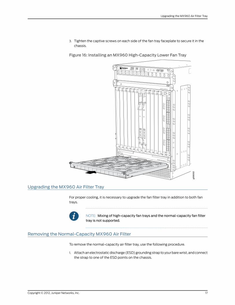
3. Tighten the captive screws on each side of the fan tray faceplate to secure it in the
chassis.
Figure 16: Installing anMX960High-Capacity Lower Fan Tray
OK
0
FAIL
ONLINE
OK
1
FAIL
ONLINE
OK
2
FAIL
ONLINE
OK
3
FAIL
ONLINE
OK
4
FAIL
ONLINE
OK
5
FAIL
ONLINE
OK
0
FAIL
ONLINE
MASTERONLINEOFFLINE
RE0
FANPEM
1
0
0 1 2 3
RE1OK
1
FAIL
ONLINE
OK
7
FAIL
ONLINE
OK
8
FAIL
ONLINE
OK
9
FAIL
ONLINE
OK
10
FAIL
ONLINE
OK
11
FAIL
ONLINE
OK
2 6
FAIL
ONLINE
ACO/LT
YELLOW ALARM RED ALARM
NC NOC NC NOC
1 01 0
1 0
1 01 0
1 10 0
1 01 01 0
g006
002
Upgrading theMX960 Air Filter Tray
For proper cooling, it is necessary to upgrade the fan filter tray in addition to both fan
trays.
NOTE: Mixing of high-capacity fan trays and the normal-capacity fan filtertray is not supported.
Removing the Normal-Capacity MX960 Air Filter
To remove the normal-capacity air filter tray, use the following procedure.
1. Attachanelectrostaticdischarge (ESD)groundingstrap toyourbarewrist, andconnect
the strap to one of the ESD points on the chassis.
17Copyright © 2012, Juniper Networks, Inc.
Upgrading the MX960 Air Filter Tray

CAUTION: Do not let fiber-optic cable hang free from the connector. Donot allow fastened loops of cable to dangle, which stresses the cable atthe fastening point.
CAUTION: Do not run the router for more than twominutes without theair filter in place.
2. Pull the filter tray release on both sides of the filter tray.
3. Slide the air filter tray out of the chassis as shown in Figure 17 on page 18.
Figure 17: Removing theNormal-Capacity Air Filter Tray from the Chassis
g006
063
Installing theMX960High-Capacity Tray and Filter
To install the high-capacity air filter, use the following procedure.
1. Verify that the air flow arrow is pointing upwards.
NOTE: The filter tray is shipped with the filter in the tray.
NOTE: Verify that you are installing the high-capacity air filter and tray, itis labelled “Filter Tray-MX960-HC.”
2. Insert the air filter tray into the chassis by sliding it straight into the chassis until it
stops as shown in Figure 18 on page 19.
Copyright © 2012, Juniper Networks, Inc.18
Upgrading MX240, MX480, and MX960 3D Universal Edge Router Power Supplies and Fan Trays

Figure 18: Inserting the High-Capacity Air Filter Tray into the Chassis
g006
064
3. Lower the cable manager back into position.
4. Rearrange the cables in the cable manager.
Power Supply Upgrade Overview
Aminimum number of power supplies must be present in the router at all times during
the upgrade procedure. Table 3 on page 19 lists theminimum number of power supplies
that must be present in the router. Theminimum configuration is unchanged with the
exception of MX960 high-capacity AC power supply which decreases from 3 to 2 per
system.
Upgrading MX-Series power supplies comprises upgrading each power supply in a
prescribed order. Upgrading an individual power supply comprises removing the
normal-capacity power supply in the slot and installing a high-capacity power supply in
that slot. The removal and installation steps are then repeated for each subsequent slot
in a prescribed order. Table 4 on page 20 outlines the upgrade sequence. If a normal
capacity power supply is not present in that slot, skip that slot.
Table 3: MinimumRequired Number of Power Supplies
MinimumRequired Number of Power Supplies
ConfigurationRouter ModelHigh-CapacityNormal-Capacity
11AC – high lineMX240
22AC – low lineMX240
11DCMX240
22AC – high lineMX480
33AC – low lineMX480
19Copyright © 2012, Juniper Networks, Inc.
Power Supply Upgrade Overview
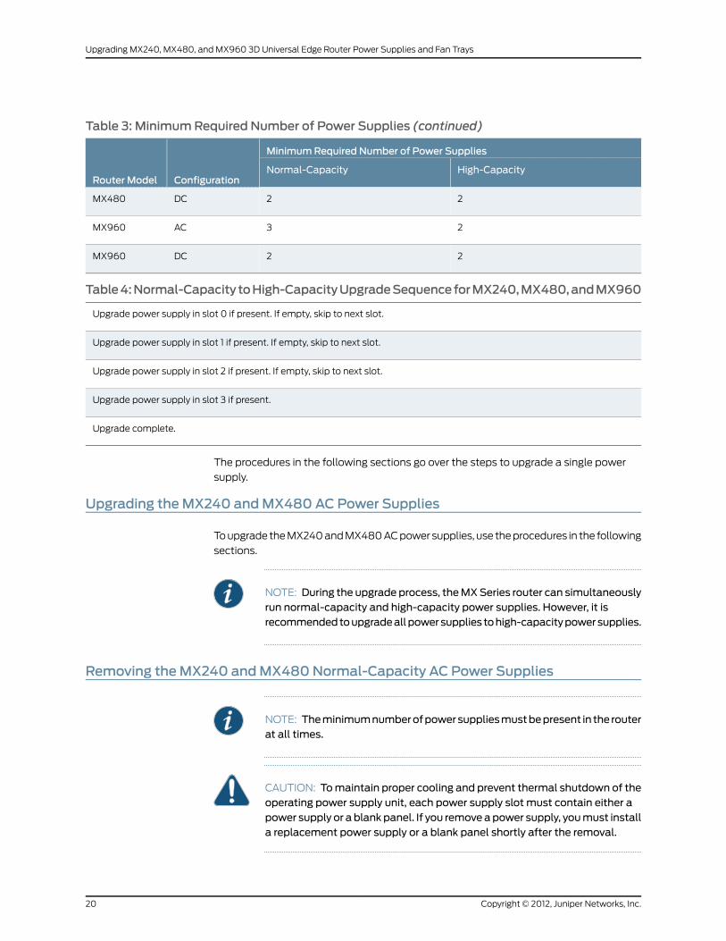
Table 3: MinimumRequired Number of Power Supplies (continued)
MinimumRequired Number of Power Supplies
ConfigurationRouter ModelHigh-CapacityNormal-Capacity
22DCMX480
23ACMX960
22DCMX960
Table4:Normal-Capacity toHigh-CapacityUpgradeSequenceforMX240,MX480,andMX960
Upgrade power supply in slot 0 if present. If empty, skip to next slot.
Upgrade power supply in slot 1 if present. If empty, skip to next slot.
Upgrade power supply in slot 2 if present. If empty, skip to next slot.
Upgrade power supply in slot 3 if present.
Upgrade complete.
The procedures in the following sections go over the steps to upgrade a single power
supply.
Upgrading theMX240 andMX480 AC Power Supplies
Toupgrade theMX240andMX480ACpower supplies, use theprocedures in the following
sections.
NOTE: During the upgrade process, theMXSeries router can simultaneouslyrun normal-capacity and high-capacity power supplies. However, it isrecommendedtoupgradeallpowersupplies tohigh-capacitypowersupplies.
Removing theMX240 andMX480Normal-Capacity AC Power Supplies
NOTE: Theminimumnumberofpowersuppliesmustbepresent in the routerat all times.
CAUTION: Tomaintain proper cooling and prevent thermal shutdown of theoperating power supply unit, each power supply slot must contain either apower supply or a blankpanel. If you removeapower supply, youmust installa replacement power supply or a blank panel shortly after the removal.
Copyright © 2012, Juniper Networks, Inc.20
Upgrading MX240, MX480, and MX960 3D Universal Edge Router Power Supplies and Fan Trays

NOTE: After powering off a power supply, wait at least 60 seconds beforeturning it back on.
To remove a normal-capacity AC power supply:
1. Attachanelectrostaticdischarge (ESD)groundingstrap toyourbarewrist, andconnect
the strap to one of the ESD points on the chassis.
2. Move the AC input switch next to the appliance inlet on the power supply to the off
(O) position.
3. Remove the power cord from the AC power source.
4. Verify that the ON LED is not lit.
5. Remove the power cord from the power supply.
6. Unscrew the captive screws on the bottom edge of the power supply.
7. Pull the power supply straight out of the chassis.
8. Go to the next section on installing a high-capacity power supply in this slot.
Installing theMX240 andMX480 ACHigh-Capacity Power Supplies
NOTE: During the upgrade process, you can simultaneously runnormal-capacity and high-capacity power supplies. However, it isrecommendedtoupgradeallpowersupplies tohigh-capacitypowersupplies.
To install a high-capacity AC power supply:
1. Attachanelectrostaticdischarge (ESD)groundingstrap toyourbarewrist, andconnect
the strap to one of the ESD points on the chassis.
2. Move theAC input switchnext to theappliance inlet on thepower supply to theoff (O)
position.
3. Using both hands, slide the power supply straight into the chassis until the power
supply is fully seated in the chassis slot as shown in Figure 19 on page 22. The power
supply faceplate should be flush with any adjacent power supply faceplate or blank
installed in the power supply slot.
4. Tighten both captive screws at the bottom of the power supply.
5. Attach the power cord to the power supply.
6. Attach the power cord to theACpower source, and switch on the dedicated customer
site circuit breaker. Follow the instructions for your site.
7. Move the AC input switch next to the appliance inlet on the power supply to the on
(|) position and observe the status LEDs on the power supply faceplate. If the power
21Copyright © 2012, Juniper Networks, Inc.
Installing the MX240 and MX480 AC High-Capacity Power Supplies

supply is correctly installed and functioning normally, theACOK andDCOK LEDs light
steadily and the PS FAIL LED is not lit.
8. Refer to Table 5 on page 32 for the next slot to upgrade. If this is the last slot, the
upgrade procedure is complete.
Figure 19: Installing an AC Power Supply
Upgrading theMX240 andMX480DC Power Supplies
Toupgrade theMX240andMX480DCpowersupplies, use theprocedures in the following
sections.
Removing theMX240 andMX480Normal-Capacity DC Power Supplies
NOTE: Theminimumnumberofpowersuppliesmustbepresent in the routerat all times. Table 3 on page 19 lists the requiredminimum number of powersupplies.
WARNING: Before performing DC power procedures, ensure that power isremoved from theDC circuit. To ensure that all power is off, locate the circuitbreaker on the panel board that services the DC circuit, switch the circuitbreaker to the off position, and tape the switch handle of the circuit breakerin the off position.
CAUTION: Tomaintain proper cooling and prevent thermal shutdown of theoperating power supply unit, each power supply slot must contain either apower supply or a blankpanel. If you removeapower supply, youmust installa replacement power supply or a blank panel shortly after the removal.
Copyright © 2012, Juniper Networks, Inc.22
Upgrading MX240, MX480, and MX960 3D Universal Edge Router Power Supplies and Fan Trays

NOTE: After powering off a power supply, wait at least 60 seconds beforeturning it back on.
To remove a DC power supply (see Figure 20 on page 23):
1. Switch off the dedicated customer site circuit breaker for the power supply being
removed. Follow your site's procedures for ESD.
2. Make sure that the voltage across the DC power source cable leads is 0 V and that
there is no chance that the cables might become active during the removal process.
3. Attachanelectrostaticdischarge (ESD)groundingstrap toyourbarewrist, andconnect
the strap to one of the ESD points on the chassis.
4. Move the power switch on the DC power supply faceplate to the off (O) position.
5. Remove the clear plastic cover protecting the terminal studs on the faceplate.
6. Remove the nut andwasher from each of the terminal studs. (Use a 7/16-in. [11-mm]
nut driver or socket wrench.)
7. Remove the cable lugs from the terminal studs.
8. Loosen the captive screws on the bottom edge of the power supply faceplate.
9. Carefully move the power cables out of the way.
10. Pull the power supply straight out of the chassis.
11. Go to the next section on installing a high-capacity power supply in this slot.
Figure 20: Removing a DC Power Supply from the Router
23Copyright © 2012, Juniper Networks, Inc.
Removing the MX240 and MX480 Normal-Capacity DC Power Supplies
Installing theMX240 andMX480DCHigh-Capacity Power Supplies
NOTE: During the upgrade process, you can simultaneously runnormal-capacity and high-capacity power supplies. However, it isrecommendedtoupgradeallpowersupplies tohigh-capacitypowersupplies.
WARNING: Before performing DC power procedures, ensure that power isremoved from theDC circuit. To ensure that all power is off, locate the circuitbreaker on the panel board that services the DC circuit, switch the circuitbreaker to the off position, and tape the switch handle of the circuit breakerin the off position.
To install a DC power supply (see Figure 22 on page 27):
1. Ensure that the voltage across the DC power source cable leads is 0 V and that there
is no chance that the cable leads might become active during installation.
2. Attachanelectrostaticdischarge (ESD)groundingstrap toyourbarewrist, andconnect
the strap to one of the ESD points on the chassis.
3. Move the power switch on the power supply faceplate to the off (O) position.
4. Using both hands, slide the power supply straight into the chassis until the power
supply is fully seated in the chassis slot. The power supply faceplate should be flush
with any adjacent power supply faceplate or blank installed in the power supply slot.
5. Using a screwdriver, loosen the captive screw holding the metal cover over the input
mode switch. Rotate themetal cover away from the inputmode switch to expose the
switch.
6. Check the setting of the input mode switch. Use a sharp, nonconductive object to
slide the switch to the desired position. Set the input mode switch to position 0 for
60-A inputandposition 1 for 70-A input. This setting is usedby thepowermanagement
software and needs to be set before on the power supply. See Changing the MX240
and MX480 DC High-Capacity Power Supply Input Mode Switch on page 43.
Copyright © 2012, Juniper Networks, Inc.24
Upgrading MX240, MX480, and MX960 3D Universal Edge Router Power Supplies and Fan Trays
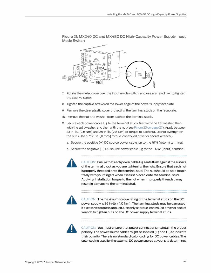
Figure 21: MX240 DC andMX480DCHigh-Capacity Power Supply InputMode Switch
g004
725
7. Rotate the metal cover over the input mode switch, and use a screwdriver to tighten
the captive screw.
8. Tighten the captive screws on the lower edge of the power supply faceplate.
9. Remove the clear plastic cover protecting the terminal studs on the faceplate.
10. Remove the nut and washer from each of the terminal studs.
11. Secure each power cable lug to the terminal studs, first with the flat washer, then
with the splitwasher, and thenwith thenut (seeFigure 23onpage27). Apply between
23 in-lb.. (2.6 Nm) and 25 in-lb. (2.8 Nm) of torque to each nut. Do not overtighten
the nut. (Use a 7/16-in. [11 mm] torque-controlled driver or socket wrench.)
a. Secure the positive (+) DC source power cable lug to the RTN (return) terminal.
b. Secure the negative (–) DC source power cable lug to the –48V (input) terminal.
CAUTION: Ensure thateachpowercable lugseats flushagainst thesurfaceof the terminal block as you are tightening the nuts. Ensure that each nutis properly threadedonto the terminal stud. Thenut shouldbeable to spinfreely with your fingers when it is first placed onto the terminal stud.Applying installation torque to the nut when improperly threadedmayresult in damage to the terminal stud.
CAUTION: Themaximum torque rating of the terminal studs on the DCpower supply is 36 in-lb. (4.0 Nm). The terminal studsmay be damagedif excessive torque is applied.Useonlya torque-controlleddriver or socketwrench to tighten nuts on the DC power supply terminal studs.
CAUTION: Youmust ensure that power connectionsmaintain the properpolarity. The power source cablesmight be labeled (+)and (–) to indicate
their polarity. There is no standard color coding for DC power cables. Thecolor coding usedby the externalDCpower source at your site determines
25Copyright © 2012, Juniper Networks, Inc.
Installing the MX240 and MX480 DC High-Capacity Power Supplies
the color coding for the leads on the power cables that attach to theterminal studs on each power supply.
NOTE: The DC power supplies in PEM0 and PEM1must be powered by
dedicated power feeds derived from feed A, and the DC power supplies
in PEM2 and PEM3must be powered by dedicated power feeds derived
fromfeedB. This configurationprovides thecommonlydeployedA/B feed
redundancy for the system.
NOTE: For information about connecting to DC power sources, see DCPower Supply Electrical Specifications for the MX480 Router.
12. Replace the clear plastic cover over the terminal studs on the faceplate.
13. Route the power cables along the cable restraint toward the left or right corner of the
chassis. If needed to hold the power cables in place, thread plastic cable ties, which
youmust provide, through the openings on the cable restraint.
14. Verify that the power cabling is correct, that the cables are not touching or blocking
access to router components, and that they do not drape where people could trip on
them.
15. Switch on the dedicated customer site circuit breakers. Follow your site's procedures
for safety and ESD.
Verify that the INPUTOK LED on the power supply is lit green.
16. On each of the DC power supplies, turn the power switch to the on (—) position.
Observe the statusLEDson thepower supply faceplate. If thepower supply is correctly
installed and functioning normally, the PWROK, BRKRON, and INPUTOK LEDs light
green steadily.
17. Refer to Table 5 on page 32 for the next slot to upgrade. If this is the last slot, the
upgrade procedure is complete.
NOTE: An SCBmust be present for the PWROK LED to go on.
Copyright © 2012, Juniper Networks, Inc.26
Upgrading MX240, MX480, and MX960 3D Universal Edge Router Power Supplies and Fan Trays
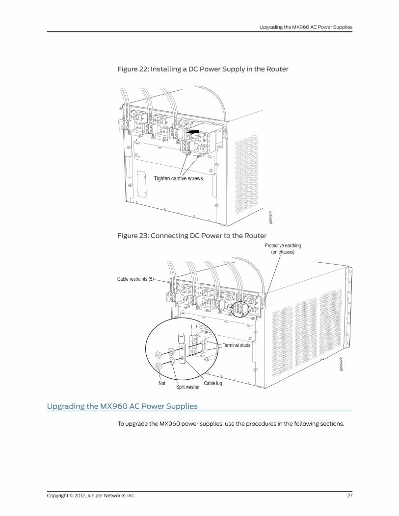
Figure 22: Installing a DC Power Supply in the Router
Figure 23: Connecting DC Power to the Router
Upgrading theMX960 AC Power Supplies
To upgrade the MX960 power supplies, use the procedures in the following sections.
27Copyright © 2012, Juniper Networks, Inc.
Upgrading the MX960 AC Power Supplies

NOTE: Before beginning this procedure, make sure that additional powerdistribution cables are in place. A second set of power cables are optional,depending on the configuration.
NOTE: Theminimumnumberofpowersuppliesmustbepresent in the routerat all times.
CAUTION: Tomaintain proper cooling and prevent thermal shutdown of theoperating power supply unit, each power supply slot must contain either apower supply or a blankpanel. If you removeapower supply, youmust installa replacement power supply or a blank panel shortly after the removal.
Removing theMX960Normal-Capacity AC Power Supplies
To remove a normal-capacity power supply, use the following procedures (see Figure
24 on page 29). Before you remove a power supply, be aware of the following:
NOTE: Theminimumnumberofpowersuppliesmustbepresent in the routerat all times.
CAUTION: Tomaintain proper cooling and prevent thermal shutdown of theoperating power supply unit, each power supply slot must contain either apower supply or a blankpanel. If you removeapower supply, youmust installa replacement power supply or a blank panel shortly after the removal.
NOTE: After powering off a power supply, wait at least 60 seconds beforeturning it back on.
To remove a normal-capacity AC power supply (see Figure 24 on page 29):
1. Move the AC input switch in the chassis above the power supply in slot 0 to the off
(O) position.
2. Remove the power cord from theACpower source. Follow the ESDanddisconnection
instructions for your site.
3. Remove the power cord from the power supply.
4. While grasping the handle on the power supply faceplate with one hand, use your
other hand to pull the spring-loaded locking pin in the release lever away from the
chassis and turn the release lever counterclockwise until it stops.
Copyright © 2012, Juniper Networks, Inc.28
Upgrading MX240, MX480, and MX960 3D Universal Edge Router Power Supplies and Fan Trays
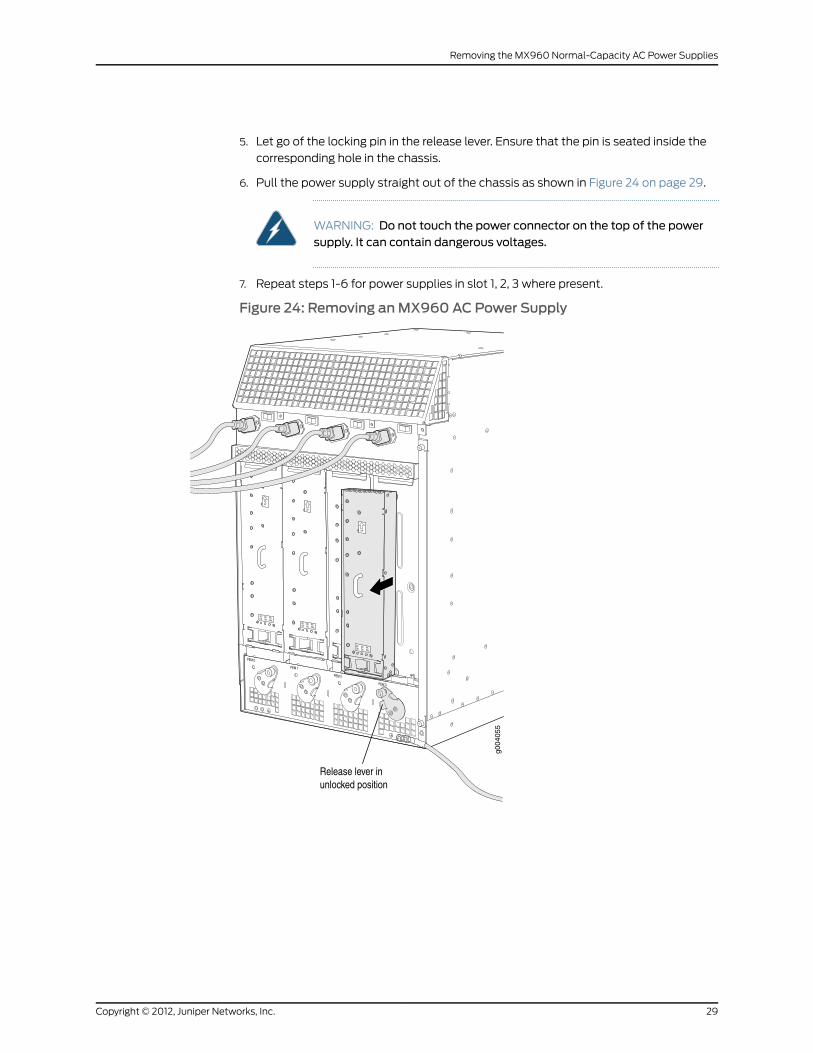
5. Let go of the locking pin in the release lever. Ensure that the pin is seated inside the
corresponding hole in the chassis.
6. Pull the power supply straight out of the chassis as shown in Figure 24 on page 29.
WARNING: Do not touch the power connector on the top of the powersupply. It can contain dangerous voltages.
7. Repeat steps 1-6 for power supplies in slot 1, 2, 3 where present.
Figure 24: Removing anMX960 AC Power Supply
29Copyright © 2012, Juniper Networks, Inc.
Removing the MX960 Normal-Capacity AC Power Supplies

Installing theMX960 ACHigh-Capacity Power Supplies
NOTE: During the upgrade process, you can simultaneously runnormal-capacity and high-capacity power supplies. However, it isrecommendedtoupgradeallpowersupplies tohigh-capacitypowersupplies.
NOTE: Aminimum of two AC nominal 220 VAC 20 amp power cords arerequired for this procedure.
To install an MX960 high-capacity AC power supply, use the following procedure (see
Figure 25 on page 30).
1. Verify that the power switch on the power supply is in the off (O) position.
2. Ensure that the release lever below the empty power supply slot is locked in the
counterclockwise position (see Figure 25 on page 30).
Figure 25: MX960with High-Capacity AC Power Supplies Installed
g006
061
AC-1 OKAC-2 OKDC OKPS FAIL
AC-1 OKAC-2 OKDC OKPS FAIL
AC-1 OKAC-2 OKDC OKPS FAIL
AC-1 OKAC-2 OKDC OKPS FAIL
Protective earthing ESD point
Power supplyejectors
AC Powersupplies
Air exhaust
Input mode switch
Copyright © 2012, Juniper Networks, Inc.30
Upgrading MX240, MX480, and MX960 3D Universal Edge Router Power Supplies and Fan Trays
If necessary, pull the spring-loaded locking pin in the release lever away from the
chassis and turn the release lever counterclockwise until it stops. Let go of the locking
pin in the release lever. Ensure that the pin is seated inside the corresponding hole in
the chassis.
3. On the power supply, rotate the metal cover away from the input mode switch to
expose the switch.
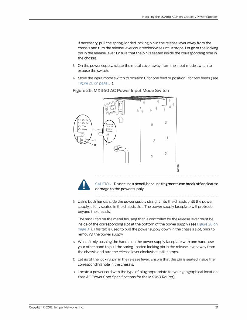
4. Move the inputmode switch to position 0 for one feed or position 1 for two feeds (see
Figure 26 on page 31).
Figure 26: MX960 AC Power Input Mode Switch
g006
057
01 1
0
CAUTION: Donotuseapencil, because fragmentscanbreakoffandcausedamage to the power supply.
5. Using both hands, slide the power supply straight into the chassis until the power
supply is fully seated in the chassis slot. The power supply faceplate will protrude
beyond the chassis.
The small tab on themetal housing that is controlled by the release lever must be
inside of the corresponding slot at the bottom of the power supply (see Figure 26 on
page 31). This tab is used to pull the power supply down in the chassis slot, prior to
removing the power supply.
6. While firmly pushing the handle on the power supply faceplate with one hand, use
your other hand to pull the spring-loaded locking pin in the release lever away from
the chassis and turn the release lever clockwise until it stops.
7. Let go of the locking pin in the release lever. Ensure that the pin is seated inside the
corresponding hole in the chassis.
8. Locate a power cord with the type of plug appropriate for your geographical location
(see AC Power Cord Specifications for the MX960 Router).
31Copyright © 2012, Juniper Networks, Inc.
Installing the MX960 AC High-Capacity Power Supplies
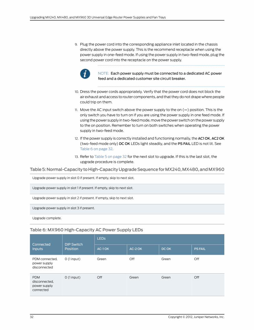
9. Plug the power cord into the corresponding appliance inlet located in the chassis
directly above the power supply. This is the recommend receptacle when using the
power supply in one-feedmode. If using the power supply in two-feedmode, plug the
second power cord into the receptacle on the power supply.
NOTE: Each power supply must be connected to a dedicated AC powerfeed and a dedicated customer site circuit breaker.
10. Dress the power cords appropriately. Verify that the power cord does not block the
air exhaustandaccess to router components, and that theydonotdrapewherepeople
could trip on them.
11. Move the AC input switch above the power supply to the on (—) position. This is the
only switch you have to turn on if you are using the power supply in one feedmode. If
using thepowersupply in two-feedmode,move thepowerswitchon thepowersupply
to the on position. Remember to turn on both switches when operating the power
supply in two-feedmode.
12. If the power supply is correctly installed and functioning normally, theAC1OK,AC2OK
(two-feedmode only)DCOK LEDs light steadily, and the PS FAIL LED is not lit. See
Table 6 on page 32.
13. Refer to Table 5 on page 32 for the next slot to upgrade. If this is the last slot, the
upgrade procedure is complete.
Table5:Normal-Capacity toHigh-CapacityUpgradeSequenceforMX240,MX480,andMX960
Upgrade power supply in slot 0 if present. If empty, skip to next slot.
Upgrade power supply in slot 1 if present. If empty, skip to next slot.
Upgrade power supply in slot 2 if present. If empty, skip to next slot.
Upgrade power supply in slot 3 if present.
Upgrade complete.
Table 6: MX960High-Capacity AC Power Supply LEDs
LEDs
DIP SwitchPosition
ConnectedInputs PS FAILDCOKAC-2 OKAC-1 OK
OffGreenOffGreen0 (1 input)PDM connected,power supplydisconnected
OffGreenGreenOff0 (1 input)PDMdisconnected,power supplyconnected
Copyright © 2012, Juniper Networks, Inc.32
Upgrading MX240, MX480, and MX960 3D Universal Edge Router Power Supplies and Fan Trays

Table 6: MX960High-Capacity AC Power Supply LEDs (continued)
LEDs
DIP SwitchPosition
ConnectedInputs PS FAILDCOKAC-2 OKAC-1 OK
OffGreenGreenGreen0 (1 input)PDM connected,PS connected
RedOffOffGreen1 (2 inputs)PDM connected,PS disconnected
RedOffGreenOff1 (2 inputs)PDMdisconnected, PSconnected
OffGreenGreenGreen1 (2 inputs)PDM connected,PS connected
Note: The correspondingappliance inlet located in the chassis directly above thepower supply is the recommend receptaclewhenusing the power supply in one feedmode. If using the power supply in two-feedmode, plug the second power cord into thereceptacle on the power supply
Note: PDM in the above table stands for Power DistributionModule.
Upgrading theMX960DC Power Supplies Overview
NOTE: Before beginning this procedure, make sure that additional powerdistribution cables are in place. A 60 amp fuse is also required. A second setof power distribution feeds is optional.
To upgrade theMX960DC power supplies, use the procedures in the following sections.
Removing a Normal-Capacity MX960DC Power Supply
NOTE: Theminimumnumberofpowersuppliesmustbepresent in the routerat all times.
WARNING: Before performing DC power procedures, ensure that power isremoved from theDC circuit. To ensure that all power is off, locate the circuitbreaker on the panel board that services the DC circuit, switch the circuitbreaker to the off position, and tape the switch handle of the circuit breakerin the off position.
33Copyright © 2012, Juniper Networks, Inc.
Upgrading the MX960 DC Power Supplies Overview
CAUTION: Tomaintain proper cooling and prevent thermal shutdown of theoperating power supply unit, each power supply slot must contain either apower supply or a blankpanel. If you removeapower supply, youmust installa replacement power supply or a blank panel shortly after the removal.
NOTE: After powering off a power supply, wait at least 60 seconds beforeturning it back on.
To remove a normal-capacity DC power supply (see Figure 27 on page 35):
1. Switch off the dedicated customer site circuit breaker for the power supply being
removed.
2. Verify that the INPUTOK LEDs on the power supply to be removed are not lit. Also
verify that the BREAKERON LED is not lit.
3. Move the DC circuit breaker on the power supply faceplate to the off (O) position.
4. Verify that the INPUTOK LEDs on the power supply to be removed are not lit. Also
verify that the BREAKERON LED is not lit.
5. Make sure that the voltage across the DC power source cable leads is 0 V and that
there is no chance that the cables might become active during the removal process.
6. Remove the clear plastic cover protecting the terminal studs on the faceplate from
the power supply in slot 0.
7. Remove the nut and washer from each of the terminal studs. (Use a 7/16-in.
[11-mm] nut driver or socket wrench.)
8. Loosen the captive screwon the cable restraint on the lower edgeof the power supply
faceplate.
9. Remove the cable lugs from the terminal studs.
10. Carefully move the power cables out of the way.
11. While grasping the handle on the power supply faceplate with one hand, use your
other hand to pull the spring-loaded locking pin in the release lever away from the
chassis and turn the release lever counterclockwise until it stops.
12. Let go of the locking pin in the release lever. Ensure that the pin is seated inside the
corresponding hole in the chassis.
13. Pull the power supply straight out of the chassis (see Figure 27 on page 35).
WARNING: Do not touch the power connector on the top of the powersupply. It can contain dangerous voltages.
14. Repeat steps 1-12 for power supplies in slot 1, 2, and 3, where present.
Copyright © 2012, Juniper Networks, Inc.34
Upgrading MX240, MX480, and MX960 3D Universal Edge Router Power Supplies and Fan Trays
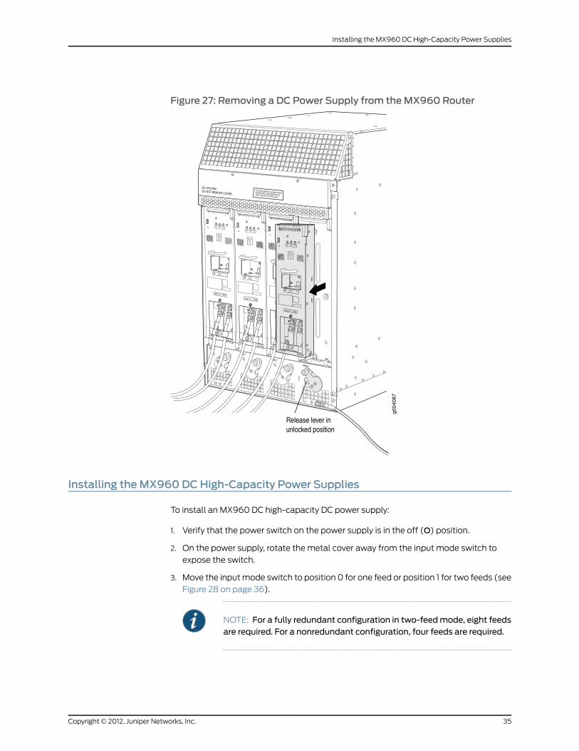
Figure 27: Removing a DC Power Supply from theMX960 Router
Installing theMX960DCHigh-Capacity Power Supplies
To install an MX960 DC high-capacity DC power supply:
1. Verify that the power switch on the power supply is in the off (O) position.
2. On the power supply, rotate the metal cover away from the input mode switch to
expose the switch.
3. Move the inputmode switch to position 0 for one feed or position 1 for two feeds (see
Figure 28 on page 36).
NOTE: For a fully redundant configuration in two-feedmode, eight feedsare required. For a nonredundant configuration, four feeds are required.
35Copyright © 2012, Juniper Networks, Inc.
Installing the MX960 DC High-Capacity Power Supplies
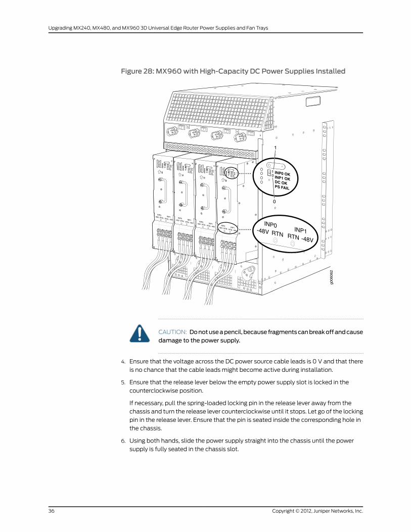
Figure 28: MX960with High-Capacity DC Power Supplies Installed
g006
062
01
1
0
CAUTION: Donotuseapencil, because fragmentscanbreakoffandcausedamage to the power supply.
4. Ensure that the voltage across the DC power source cable leads is 0 V and that there
is no chance that the cable leads might become active during installation.
5. Ensure that the release lever below the empty power supply slot is locked in the
counterclockwise position.
If necessary, pull the spring-loaded locking pin in the release lever away from the
chassis and turn the release lever counterclockwise until it stops. Let go of the locking
pin in the release lever. Ensure that the pin is seated inside the corresponding hole in
the chassis.
6. Using both hands, slide the power supply straight into the chassis until the power
supply is fully seated in the chassis slot.
Copyright © 2012, Juniper Networks, Inc.36
Upgrading MX240, MX480, and MX960 3D Universal Edge Router Power Supplies and Fan Trays
The small tab on themetal housing that is controlled by the release lever must be
inside of the corresponding slot at the bottom of the power supply. This tab is used
to pull the power supply down in the chassis slot, prior to removing the power supply.
7. While firmly pushing the handle on the power supply faceplate with one hand, use
your other hand to pull the spring-loaded locking pin in the release lever away from
the chassis and turn the release lever clockwise until it stops.
8. Let go of the locking pin in the release lever. Ensure that the pin is seated inside the
corresponding hole in the chassis.
9. Remove the cover protecting the terminal studs on the faceplate.
10. Remove the nut and washer from each of the terminal studs.
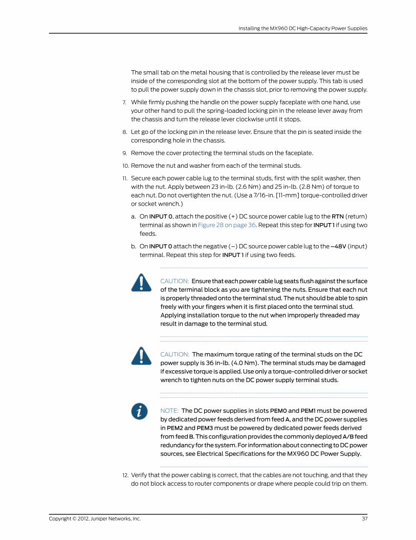
11. Secure each power cable lug to the terminal studs, first with the split washer, then
with the nut. Apply between 23 in-lb. (2.6 Nm) and 25 in-lb. (2.8 Nm) of torque to
each nut. Do not overtighten the nut. (Use a 7/16-in. [11-mm] torque-controlled driver
or socket wrench.)
a. On INPUT0, attach the positive (+) DC source power cable lug to theRTN (return)
terminal as shown in Figure 28 on page 36. Repeat this step for INPUT 1 if using two
feeds.
b. On INPUT0attach the negative (–)DC source power cable lug to the–48V (input)
terminal. Repeat this step for INPUT 1 if using two feeds.
CAUTION: Ensure thateachpowercable lugseats flushagainst thesurfaceof the terminal block as you are tightening the nuts. Ensure that each nutis properly threadedonto the terminal stud. Thenut shouldbeable to spinfreely with your fingers when it is first placed onto the terminal stud.Applying installation torque to the nut when improperly threadedmayresult in damage to the terminal stud.
CAUTION: Themaximum torque rating of the terminal studs on the DCpower supply is 36 in-lb. (4.0 Nm). The terminal studsmay be damagedif excessive torque is applied.Useonlya torque-controlleddriver or socketwrench to tighten nuts on the DC power supply terminal studs.
NOTE: The DC power supplies in slots PEM0 and PEM1must be powered
bydedicatedpower feedsderived from feedA, and theDCpower supplies
in PEM2 and PEM3must be powered by dedicated power feeds derived
fromfeedB. This configurationprovides thecommonlydeployedA/B feed
redundancy for thesystem.For informationaboutconnectingtoDCpowersources, see Electrical Specifications for the MX960 DC Power Supply.
12. Verify that the power cabling is correct, that the cables are not touching, and that they
do not block access to router components or drape where people could trip on them.
37Copyright © 2012, Juniper Networks, Inc.
Installing the MX960 DC High-Capacity Power Supplies

13. Replace the clear plastic cover over the terminal studs on the faceplate.
14. Switch on the dedicated customer site circuit breaker.
15. Verify that the INPUT 0OK or INPUT 1 OK LEDs on the power supply are lit green
steadily. If using two feeds, verify that both INPUT 0OK and INPUT 1 OK LEDs on the
power supply are lit steadily. The INPUT OKwill be lit amber if that input’s voltage is
in reverse polarity. Check the polarity of the power cables to fix the condition (see
Figure 29 on page 39 and Table 7 on page 38.
16. Move the switch to the on (|) position.
17. Verify that the DCOK LED is lit green steadily. See Table 7 on page 38 for information
on MX960 high-capacity DC LEDs.
Table 7: MX960High-Capacity DC Power Supply LEDs
LEDsDIPSwitchPositionConnected Inputs PS FAILDCOKINP-1 OKINP-0OK
OffGreenOffGreen0 (1input)
INP0 connected, INP1 disconnected
OffGreenGreenOffINP0 disconnected, INP1 connected
OffGreenGreenGreenINP0 connected, INP1 connected
RedOffOffGreen1 (2inputs)
INP0 connected, INP1 disconnected
RedOffGreenOffINP0 disconnected, INP1 connected
OffGreenGreenGreenINP0 connected, INP1 connected
18. Repeat steps 1-17 for installing power supplies in slots 1, 2, 3 where present.
Copyright © 2012, Juniper Networks, Inc.38
Upgrading MX240, MX480, and MX960 3D Universal Edge Router Power Supplies and Fan Trays
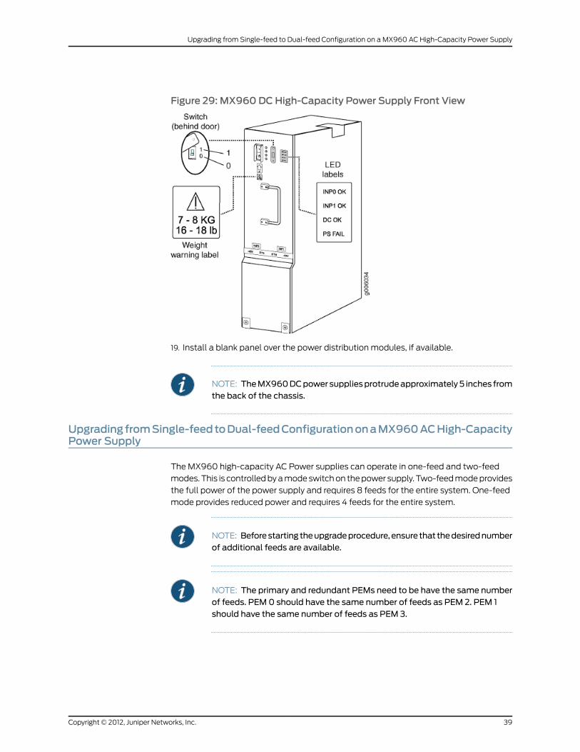
Figure 29: MX960DCHigh-Capacity Power Supply Front View
19. Install a blank panel over the power distribution modules, if available.
NOTE: TheMX960DCpower suppliesprotrudeapproximately5 inches fromthe back of the chassis.
Upgrading fromSingle-feedtoDual-feedConfigurationonaMX960ACHigh-CapacityPower Supply
The MX960 high-capacity AC Power supplies can operate in one-feed and two-feed
modes. This is controlledbyamodeswitchon thepower supply. Two-feedmodeprovides
the full power of the power supply and requires 8 feeds for the entire system. One-feed
mode provides reduced power and requires 4 feeds for the entire system.
NOTE: Beforestarting theupgradeprocedure,ensure that thedesirednumberof additional feeds are available.
NOTE: The primary and redundant PEMs need to be have the same numberof feeds. PEM 0 should have the same number of feeds as PEM 2. PEM 1should have the same number of feeds as PEM 3.
39Copyright © 2012, Juniper Networks, Inc.
Upgrading from Single-feed to Dual-feed Configuration on a MX960 AC High-Capacity Power Supply
NOTE: Thepowersupplies inPEM0andPEM1mustbepoweredbydedicatedpower feeds derived from feed A, and the power supplies in PEM 2 and PEM3must bepoweredbydedicatedpower feeds from feedB. This configurationprovides the commonly deployed A/B feed redundancy for the system.
NOTE: When upgrading the feeds for multiple power supplies, follow theupgrade sequence in Table 5 on page 32 for the order of the slots to upgrade.
To upgrade from a single-feed to dual feeds:
1. Locate a power cord with the type of plug for your geographical location (see AC
Power Cord Specifications for the MX960 Router).
2. Plug the power cord into the receptacle on the power supply.
3. Insert the power cord plug into an external AC power source receptacle.
4. Dress the power cords appropriately. Verify that the power cord does not block the
air exhaust. Drape the power cord where people cannot trip on it.
5. On the power supply, rotate the metal cover away from the input mode switch to
expose the switch.
6. Move the input mode switch to position 1 for two feeds (see Figure 26 on page 31).
7. Move the AC input switch in the chassis to the ON position.
8. If the power supply is correctly installed and functioning normally, the AC-1 OK, AC-2
OK, andDCOKLEDs light steadily and thePSFAILLED is not lit. SeeTable6onpage32
for information on MX960 high-capacity AC LEDs.
UpgradingfromSingle-FeedtoDual-FeedConfigurationonanMX960DCHigh-CapacityPower Supply
The MX960 high-capacity DC Power supplies can operate in one-feed and two-feed
modes. This is controlledbyamodeswitchon thepower supply. Two-feedmodeprovides
the full power of the power supply and requires 8 feeds for the entire system. One-feed
mode provides reduced power and requires four feeds for the entire system.
CAUTION: Do no upgrade the feeds on the high-capacity DC power supplywhile it is in operation. Make sure the covers on the adjacent power suppliesare in place and there is no chance of accidentally touching a live feed.
CAUTION: Youmust ensure that power connectionsmaintain the properpolarity. The power source cablesmight be labeled (+) and (–) to indicate
their polarity. There is no standard color coding for DC power cables. The
Copyright © 2012, Juniper Networks, Inc.40
Upgrading MX240, MX480, and MX960 3D Universal Edge Router Power Supplies and Fan Trays

color coding used by the external DC power source at your site determinesthe color coding for the leads on the power cables that attach to the terminalstuds on each power supply.
NOTE: Beforestarting theupgradeprocedure,ensure that thedesirednumberof additional feeds are available.
NOTE: The primary and redundant PEMs need to be have the same numberof feeds. PEM 0 should have the same number of feeds as PEM 2. PEM 1should have the same number of feeds as PEM 3.
NOTE: Thepowersupplies inPEM0andPEM1mustbepoweredbydedicatedpower feedsderived from feedA, and thepower supplies inPEM2andPEM3must be powered by dedicated power feeds from feed B. This configurationprovides the commonly deployed A/B feed redundancy for the system.
NOTE: When upgrading the feeds for multiple power supplies, follow theupgrade sequence in Table 5 on page 32 for the order of the slots to upgrade.
To upgrade from a single-feed configuration to a dual-feed configuration on an MX960
DC high-capacity power supply:
1. Switch off the dedicated customer site circuit breaker for the power supply being
upgraded. Follow your site’s procedures for electrostatic discharge (ESD).
2. Verify that the power switch on the power supply is also in the off (O) position.
3. On the power supply, rotate the metal cover away from the input mode switch to
expose the switch.
4. Move the input mode switch to position 1 for two feeds (see Figure 26 on page 31).
5. Ensure that the voltage across the DC power source cable leads is 0 V and that there
is no chance the cable leads might become active during installation.
6. Attachanelectrostaticdischarge (ESD)groundingstrap toyourbarewrist, andconnect
the strap to an approved site ESD grounding point. See the instructions for your site.
7. Remove the cover protecting the terminal studs on the faceplate.
8. Remote the nut and washer from each of the terminal studs.
a. On INPUT 1, attach the positive (+) DC source power cable lug to the RTN (return)
terminal as shown in Figure 28 on page 36.
41Copyright © 2012, Juniper Networks, Inc.
Upgrading from Single-Feed to Dual-Feed Configuration on an MX960 DC High-Capacity Power Supply

b. On INPUT 1 attach the negative (–) DC source power cable lug to the –48V (input)
terminal.
9. Secure each power cable lug, first with the split washer, then with the nut. Apply
between 23 lb-in. (2.6 Nm) and 25 lb-in. (2.8 Nm) of torque to each nut. Do not
overtighten thenut. (Usea7/16-in. [11-mm] torque-controlleddriveror socketwrench.)
CAUTION: Ensure thateachpowercable lugseats flushagainst thesurfaceof the terminal block as you are tightening the nuts. Ensure that each nutis properly threadedonto the terminal stud. Thenut shouldbeable to spinfreely with your fingers when it is first placed onto the terminal stud.Applying installation torque to the nut when improperly threadedmayresult in damage to the terminal stud.
CAUTION: Themaximum torque rating of the terminal studs on the DCpower supply is 36 lb-in. (4.0 Nm). The terminal studsmay be damagedif excessive torque is applied.Useonlya torque-controlleddriver or socketwrench to tighten nuts on the DC power supply terminal studs.
CAUTION: Youmust ensure that power connectionsmaintain the properpolarity. The power source cablesmight be labeled (+)and (–) to indicate
their polarity. There is no standard color coding for DC power cables. Thecolor coding usedby the externalDCpower source at your site determinesthe color coding for the leads on the power cables that attach to theterminal studs on each power supply.
10. Verify that the power cabling is correct, that the cables are not touching, and that they
do not block access to router components or drape where people could trip on them.
11. Replace the clear plastic cover over the terminal studs on the faceplate.
12. Switch on the dedicated customer site circuit breaker.
13. Verify that the INPUT 0OK or INPUT 1 OK LEDs on the power supply are lit steadily. If
using two feeds, verify that both INPUTOK LEDs on the power supply are lit steadily
14. Move the switch to the on (|) position.
15. Verify that the DCOK LED is lit green.
Copyright © 2012, Juniper Networks, Inc.42
Upgrading MX240, MX480, and MX960 3D Universal Edge Router Power Supplies and Fan Trays

Changing theMX240andMX480DCHigh-Capacity Power Supply InputModeSwitch
The inputmode switch determines the capability of the feed, which in turn is used by the
power management software. Move the input switch to position 0 for 60-A input and
position 1 for 70-A input.
NOTE: Do not set the input mode switch if the power supply is installed inthechassis. If thepowersupply isalready installed, youmust remove itbeforesetting the input mode switch.
To set the input mode switch:
1. Using a screwdriver, loosen the captive screw holding the metal cover over the input
mode switch.
2. Rotate the metal cover away from the input mode switch to expose the switch.
3. Check the setting of the input mode switch (see Figure 30 on page 43.
4. Use a sharp, nonconductive object to slide the switch to the desired position.
Figure 30:MX240DC andMX480DCHigh-Capacity Power Supply InputMode Switch
g004
725
CAUTION: Donotuseapencil, because fragmentscanbreakoffandcausedamage to the power supply.
5. Rotate the metal cover over the input mode switch, and use a screwdriver to tighten
the captive screw.
JUNOSDocumentation and Release Notes
For a list of related JUNOS documentation, see
http://www.juniper.net/techpubs/software/junos/ .
If the information in the latest release notes differs from the information in the
documentation, follow the JUNOS Release Notes.
43Copyright © 2012, Juniper Networks, Inc.
Changing the MX240 and MX480 DC High-Capacity Power Supply Input Mode Switch
To obtain the most current version of all Juniper Networks®technical documentation,
see the product documentation page on the Juniper Networks website at
http://www.juniper.net/techpubs/ .
Requesting Technical Support
Technical product support is available through the JuniperNetworksTechnicalAssistance
Center (JTAC). If you are a customer with an active J-Care or JNASC support contract,
or are covered under warranty, and need postsales technical support, you can access
our tools and resources online or open a case with JTAC.
• JTAC policies—For a complete understanding of our JTAC procedures and policies,
review the JTAC User Guide located at
http://www.juniper.net/us/en/local/pdf/resource-guides/7100059-en.pdf .
• Product warranties—For product warranty information, visit
http://www.juniper.net/support/warranty/ .
• JTAC Hours of Operation —The JTAC centers have resources available 24 hours a day,
7 days a week, 365 days a year.
Self-Help Online Tools and Resources
For quick and easy problem resolution, Juniper Networks has designed an online
self-service portal called the Customer Support Center (CSC) that provides youwith the
following features:
• Find CSC offerings: http://www.juniper.net/customers/support/
• Find product documentation: http://www.juniper.net/techpubs/
• Find solutions and answer questions using our Knowledge Base: http://kb.juniper.net/
• Download the latest versions of software and review release notes:
http://www.juniper.net/customers/csc/software/
• Search technical bulletins for relevant hardware and software notifications:
https://www.juniper.net/alerts/
• Join and participate in the Juniper Networks Community Forum:
http://www.juniper.net/company/communities/
• Open a case online in the CSC Case Management tool: http://www.juniper.net/cm/
Toverify serviceentitlementbyproduct serial number, useourSerialNumberEntitlement
(SNE) Tool: https://tools.juniper.net/SerialNumberEntitlementSearch/
Opening a Casewith JTAC
You can open a case with JTAC on theWeb or by telephone.
• Use the Case Management tool in the CSC at http://www.juniper.net/cm/ .
• Call 1-888-314-JTAC (1-888-314-5822 toll-free in the USA, Canada, and Mexico).
Copyright © 2012, Juniper Networks, Inc.44
Upgrading MX240, MX480, and MX960 3D Universal Edge Router Power Supplies and Fan Trays
For international or direct-dial options in countries without toll-free numbers, visit us at
http://www.juniper.net/support/requesting-support.html
Revision History
July 2012—Made changes to the High Capacity DC Power Supply graphic to include a
call out showing the dip-switch position settings “0” and “1”
April 2011 —Mademinor document modifications.
February 2011— Added various procedural document enhancements, added additional
illustrations and tables.
December 2010— Added note regarding required feeds for MX960 DC high-capacity
power supplies.
August 2010— Added MX960 DC high-capacity power supply content.
April 2010— Initial release.
Copyright © 2012, Juniper Networks, Inc. All rights reserved.
Juniper Networks, Junos, Steel-Belted Radius, NetScreen, and ScreenOS are registered trademarks of Juniper Networks, Inc. in the UnitedStates and other countries. The Juniper Networks Logo, the Junos logo, and JunosE are trademarks of Juniper Networks, Inc. All othertrademarks, service marks, registered trademarks, or registered service marks are the property of their respective owners.
Juniper Networks assumes no responsibility for any inaccuracies in this document. Juniper Networks reserves the right to change, modify,transfer, or otherwise revise this publication without notice.
Products made or sold by Juniper Networks or components thereof might be covered by one or more of the following patents that areowned by or licensed to Juniper Networks: U.S. Patent Nos. 5,473,599, 5,905,725, 5,909,440, 6,192,051, 6,333,650, 6,359,479, 6,406,312,6,429,706, 6,459,579, 6,493,347, 6,538,518, 6,538,899, 6,552,918, 6,567,902, 6,578,186, and 6,590,785.
45Copyright © 2012, Juniper Networks, Inc.
Requesting Technical Support