Embed Size (px)
Citation preview
Networked Digital Media Standards
A UPnP / DLNA Overview
Allegro Software Development Corporation
1740 Massachusetts Avenue
Boxborough, MA 01719
www.allegrosoft.com
Understanding DLNA 2 Allegro Software Development Corporation
Networked Digital Media StandardsA UPnP / DLNA Overview
Table of Contents
Executive Summary . . . . . . . . . . . . . . . . . . . . . . . . . . . . . . . . . . . . . . . . . . . . . . . . . . . . . . . . . . . . . . . . . 3Introduction . . . . . . . . . . . . . . . . . . . . . . . . . . . . . . . . . . . . . . . . . . . . . . . . . . . . . . . . . . . . . . . . . . . . . . . . . 4
Rise of the Digital Home 4The Evolution of DLNA 5
DLNA Device Model . . . . . . . . . . . . . . . . . . . . . . . . . . . . . . . . . . . . . . . . . . . . . . . . . . . . . . . . . . . . . . . . . 7Devices 7Services 7Control Points 7
DLNA Device Classes . . . . . . . . . . . . . . . . . . . . . . . . . . . . . . . . . . . . . . . . . . . . . . . . . . . . . . . . . . . . . . . . 8Home Network Device 8
Digital Media Server 8Digital Media Player 9Digital Media Renderer 9Digital Media Controller 9Digital Media Printer 9
Mobile Handheld Device 10Home Infrastructure Device 11
DLNA Architecture. . . . . . . . . . . . . . . . . . . . . . . . . . . . . . . . . . . . . . . . . . . . . . . . . . . . . . . . . . . . . . . . . 13Media Formats 13Media Transport 14Media Management 14
Content Directory 14Connection Management 15AV Transport 15Rendering Control 16
Device Discovery and Control 16Discovery 17Device Description 17Service Description 18Control 18Eventing 19Presentation 20
Network Stack 21Network Connectivity 22
Certification . . . . . . . . . . . . . . . . . . . . . . . . . . . . . . . . . . . . . . . . . . . . . . . . . . . . . . . . . . . . . . . . . . . . . . . . 23About Allegro . . . . . . . . . . . . . . . . . . . . . . . . . . . . . . . . . . . . . . . . . . . . . . . . . . . . . . . . . . . . . . . . . . . . . . 25
October 26, 2006 Understanding DLNA 3
Executive Summary Over the past few years, consumers have embraced digital
technologies. Driven by broadband links to the Internet, wired and
wireless home networks, and digital devices such as music players,
digital cameras, and personal video recorders, they are acquiring,
enjoying, and managing a flood of digital content. All of this “digital
entertainment” has led them to demand device interoperability, so that
they can easily share their pictures, audio, and video throughout their
home.
In response, the leading manufacturers in the Consumer Electronics,
Mobile Device, and Personal Computer marketplaces have banded
together to create an interoperability solution for their diverse
products. This organization is the Digital Living Network Alliance
(DLNA), and its mission is simple – seamless integration of the
consumer’s digital devices and content throughout the home.
In order to achieve its goal as quickly and painlessly as possible,
DLNA elected to base their solution on established industry standards
developed by standards bodies and special interest groups such as the
Internet Engineering Task Force (IETF), World Wide Web
Consortium (W3C), Motion Picture Experts Group (MPEG), and
Universal Plug and Play Forum (UPnP).
Thus, the DLNA Interoperability Guidelines require all devices to
have an Ethernet, WiFi, or BlueTooth network connection, use TCP/IP
for networking, and implement HTML and SOAP for media transport
and management. Media Formats are also specified, with JPEG,
LPCM, and MPEG2 support required for image, audio, and video
devices respectively. To complement its detailed interoperability
guidelines, DLNA also developed a comprehensive certification
process and logo program to ensure consumers that products based on
DLNA standards deliver the experience that consumers expect – they
just work!
Understanding DLNA 4 Allegro Software Development Corporation
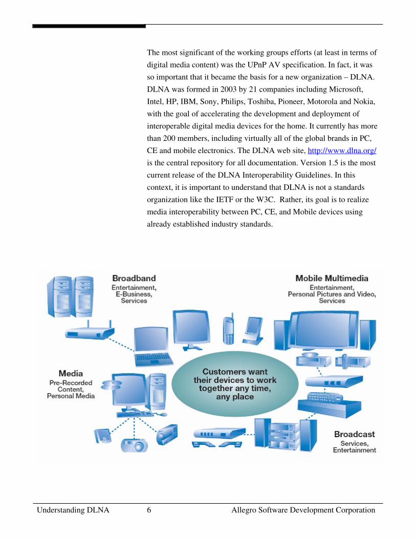
Introduction The Rise of the Digital HomeThe past few years witnessed the start of a major revolution in the
home. Consumers began to go “digital”, acquiring, enjoying, and
managing an ever growing volume of digital content – images from
their digital cameras and cell phones, audio downloaded from Internet
music stores and “ripped” from CD’s on a home PC, video from their
Tivo and DVD’s for their DVD Players. And with that transition
comes a new required feature for the device manufacturers in the
Consumer Electronics (CE), Mobile Device, and Personal Computer
(PC) domains – interoperability. Consumers want an environment
where all the devices in the home are capable of sharing digital
content—regardless of the source—across the home network. And not
one that requires a technical wizard to install and configure. They
should be able to easily connect all of their equipment and readily
share their growing libraries of digital content. In short, any device,
any time, any place, and any content.
This vision of the digital home is one that integrates the PC, CE, and
Mobile Device worlds through a seamless, interoperable network, and
provides a unique opportunity for manufacturers and consumers alike.
It is also one that requires a common set of industry design guidelines
to allow companies to participate in the evolving marketplace, while
preserving the ability to differentiate products via innovation,
simplicity, and value.
The Digital Living Network Alliance (DLNA) was formed to address
the need for a common set of industry design guidelines. The DLNA
Home Networked Device Interoperability Guidelines were created by
a unique cross-industry effort that combined the efforts of over 100
Consumer Electronics, PC and Mobile Device companies from around
the world who worked together with the aim of achieving the world’s
first substantial approach to true interoperability between personal
computers, consumer electronics, and mobile devices. The
Interoperability Guidelines provide product developers with a long-
term architectural view, plus specific guidance for IP-networked
platforms, devices and applications in the home.
October 26, 2006 Understanding DLNA 5
The Evolution of DLNA The ability of DLNA to deliverable workable interoperability
guidelines in less than 12 months is largely due to the pioneering
efforts of the Universal Plug and Play Forum (UPnP Forum). The
UPnP Forum, http://www.upnp.org/ was established by 14 major PC
and CE manufacturers in 1999. Founding members include Microsoft,
Intel, HP, Sony, Canon and Panasonic, and today it has more than 800
member companies from industries as diverse as personal computers,
consumer electronics, telecom, home automation, security, printing,
photography, and building controls. The mission of the Forum is
simple: interoperability between devices using industry standards. To
that end, the Forum selected TCP/IP as the basis for all network
connectivity. Added to TCP/IP were Web standards such as HTTP,
HTML, XML, and SOAP that provided the framework for device
discovery, device and services description, control, and presentation.
With the core architecture defined, the Forum established a series of
working groups to define device and service profiles for specific
device categories. These categories include Audio/Video (AV),
Internet Gateway Device (IGD), Printing, Scanning, Lighting Control,
HVAC, and a number of others. The working groups – composed of
member companies from relevant industries – delivered a series of
XML schemas representing the baseline set of functions and services
that each specific device type was required to support.
Understanding DLNA 6 Allegro Software Development Corporation
The most significant of the working groups efforts (at least in terms of
digital media content) was the UPnP AV specification. In fact, it was
so important that it became the basis for a new organization – DLNA.
DLNA was formed in 2003 by 21 companies including Microsoft,
Intel, HP, IBM, Sony, Philips, Toshiba, Pioneer, Motorola and Nokia,
with the goal of accelerating the development and deployment of
interoperable digital media devices for the home. It currently has more
than 200 members, including virtually all of the global brands in PC,
CE and mobile electronics. The DLNA web site, http://www.dlna.org/
is the central repository for all documentation. Version 1.5 is the most
current release of the DLNA Interoperability Guidelines. In this
context, it is important to understand that DLNA is not a standards
organization like the IETF or the W3C. Rather, its goal is to realize
media interoperability between PC, CE, and Mobile devices using
already established industry standards.
October 26, 2006 Understanding DLNA 7
DLNA Device Model The device model used by DLNA is derived from the UPnP Forum
fundamental device model. This model consists of Devices,
Services, and Control Points.
Devices are network entities that provide services and can contain
other nested devices. An example would be a VCR. It is a device
that provides a tape transport service, a tuner service, and a timing
service, while a DVD/VCR Combo would have all those services
plus a nested DVD device.
Services are the basic unit of control. They provide actions, and
maintain status via state variables. A VCR’s tape transport service
has actions such as play, fast-forward, and rewind, and a state
variable for the tape counter.
Control Points are network entities that are capable of discovering
and controlling other devices on the network. Although a Control
Point may be managing multiple devices, all interactions occur
only between the Control Point and the individual device. The
Control Point coordinates the operation of each device to yield the
desired final result.
With the development of the UPnP AV (and thus DLNA)
specifications for digital media content devices, the basic device
model was extended. All control interaction still only passes
between Control Point and Device(s), but the Devices themselves
interact with each other to pass digital content using a non-UPnP
(“out-of-band”) communications protocol. This might be an
Ethernet connection between a PC sending audio to a stereo system
or an s-video cable between a DVD player and a TV monitor. In
summary, the Control Point configures the Devices as needed,
initiates the flow of content, and gets out of the way.
Understanding DLNA 8 Allegro Software Development Corporation
DLNA Device Classes In order to better define the characteristics of devices and the
services they offer, the DLNA Interoperability Guidelines define
twelve Device Classes organized into three Device Categories.
Device Categories are based on a shared set of media formats and
network connections that exist within a specific environment, with
the focus on interoperability between devices within that category.
This does not prevent a device from belonging to more than one
device category. All that is required is compliance with the media
formats and network connectivity of both categories. A Device
Class specifies the functional capabilities of a device regardless of
its physical attributes. In fact, a single physical device can, and
frequently does incorporate multiple Device Classes. Since DLNA
certifies at the Device Class, any certified product must comply
with all the requirements of its Device Class.
The Home Network Device (HND) category is made up of five
Device Classes that are in use in the home network, and rely on the
same media formats and network connectivity requirements.
• Digital Media Server (DMS)
Acquires, records, stores, and makes available digital media
content, as well as enforcing content protection requirements.
DMS products will often have intelligence, such as device and
user services management, rich user interfaces and media
management functions, including aggregation, distribution, and
archiving. Examples of DMS devices include:
o PC Server on an Ethernet based home network
o Personal Video Recorder
o Advanced Set-top Boxes
o Dedicated Music Servers
o CD/DVD Jukebox
o Digital Cameras and Camcorders
o Cell Phones with Digital Cameras
October 26, 2006 Understanding DLNA 9
• Digital Media Player (DMP)
Finds content offered by a DMS and provides playback and
rendering capabilities. DMPs are not visible to other devices on
the network such as DMCs. Examples of DMP devices include:
o Digital TVs
o Stereo / Home Theater Systems
o Game Consoles
o PDAs
o Multimedia Mobile Phones
• Digital Media Renderer (DMR)
Similar to DMPs in that they render or play content they
receive from a DMS. Unlike DMPs, they are unable to find
content on the network, and must be setup by another network
entity – a DMC. A combination DMP/DMR device can both
find a DMS on its own, or be controlled by an external DMC.
• Digital Media Controller (DMC)
Finds content offered by a DMS and matches it to the
rendering capabilities of a DMR, setting up the connections
between the DMS and DMR. An intelligent remote control is
one example of a DMC device; a personal digital assistant or
multimedia mobile phone can also function as a DMC.
• Digital Media Printer (DMPr)
Provides printing services to the DLNA home network. Photo
printing is the primary usage of a DMPr, but more traditional
printing applications also support a DMPr. When selected for
media output, a DMPr combines images with an XHTML
template to create the printed page. DLNA provides several
basic photo templates to assist new vendors in quickly adding
photo printing to their DLNA device. It is straightforward to
add printing to device applications because the DMPr is based
on the UPnP Print Service and the W3C XHTML Print
specification. Some examples of DMPr devices include a
networked photo printer and a networked all-in-one printer.
Understanding DLNA 10 Allegro Software Development Corporation
Also, an application running on a PC may expose DMPr
functionality to an ordinary USB-attached printer.
The Mobile Handheld Device (MHD) category is made up of five
Device Classes that share the same usages models as the HND
Device Category, but have different requirements for media format
and network connectivity. The MHD category includes these
Device Classes and functionalities:
• Mobile Digital Media Server (M-DMS)
Offers and distributes content. A mobile phone and a portable
music player are examples of M-DMS devices.
• Mobile Digital Media Player (M-DMP)
Finds content offered by a M-DMS and plays the content
locally on the M-DMP. A media tablet designed for viewing
multimedia content is an example of a M-DMP device.
• Mobile Digital Media Controller (M-DMC)
Finds content offered by an M-DMS and match it to the
rendering capabilities of a DMR, setting up the connections
between the server and renderer. A personal digital assistant
and an intelligent remote control are examples of M-DMC
devices.
• Mobile Digital Media Uploader (M-DMU)
Sends content to an M-DMS with upload functionality. A
digital camera and a camera phone are examples of M-DMU
devices.
• Mobile Digital Media Downloader (M-DMD)
Finds and downloads content exposed by an M-DMS and plays
the content locally on the M-DMD after download. A portable
music player is an example of a M-DMD device.
October 26, 2006 Understanding DLNA 11
The Home Infrastructure Device (HID) category is made up of
two Device Classes. These devices are intended to allow HNDs
and MHDs to interoperate.
• Mobile Network Connectivity Function (M-NCF)
devices provide a bridging function between the MHD network
connectivity and the HND network connectivity.
• Media Interoperability Unit (MIU)
devices provide content transformation between required media
formats for the HND Device Category and the MHD Device
Category.
The twelve devices classes provide plenty of opportunity for sharing
digital content across the home network. Today, the most common
DLNA usage is music sharing. A typical scenario might include
multiple music servers (DMS) such as a CD jukebox attached to the
network with a digital media adapter, a PC Server with music
downloaded from the Internet, and a dedicated, hard drive based music
server. Multiple users could listen to the available content from a
music player (DMP) anywhere in the house – a high-end component
system in the living room, a mini stereo in the garage, or a PC in the
den.
Distributing digital video across the home network is another rapidly
developing usage. The major television vendors were showing flat
screen TVs with an integrated DMP at CES 2006, setting the stage for
the widespread sharing of video. In this case, the video servers (DMS)
will be personal video recorders, advanced set-top boxes, PCs with
Internet content, and DVD jukeboxes. In addition, current generation
TVs can be attached to the network via digital media adapters,
allowing them to share the same content. This will also allow you start
watching a show on the large screen TV in the living room and finish
watching on the bedroom TV without missing a beat.
Understanding DLNA 12 Allegro Software Development Corporation
Another rapidly developing area is the sharing of digital images.
Today, most digital image sharing is done by looking over someone’s
shoulder at pictures on a digital camera or cell phone. With DLNA
enabled device like digital cameras, photo printers, and digital picture
frames, sharing becomes a whole new experience. Digital cameras can
connect to the home network via built-in WiFi or a network dock and
act as an image server (DMS) for the home network. The images can
then be viewed on any TV in the house, stored in the family photo
archive on the PC in the den, printed on the photo printer, and
uploaded to a digital picture frame for an impromptu slide show. Even
cell phone/camera combinations can act as image servers via native
Bluetooth support or the bridging provided by the M-NCF device
class.
Using a cell phone/camera as an image server for the home network is
just one example of how MHDs can interoperate with a home’s HNDs
over the home network, permitting a variety of usage scenarios.
Examples include:
o A PDA can function as an intelligent remote control for a
digital media server and renderer. Intelligent cell phones
can also server as controllers (DMC).
o A portable music player can pull audio from a PC based
media server for later listening (M-DMD).
o A portable music player can upload audio to a PC based
media server (DMS) so it can be shared throughout the
home.
October 26, 2006 Understanding DLNA 13
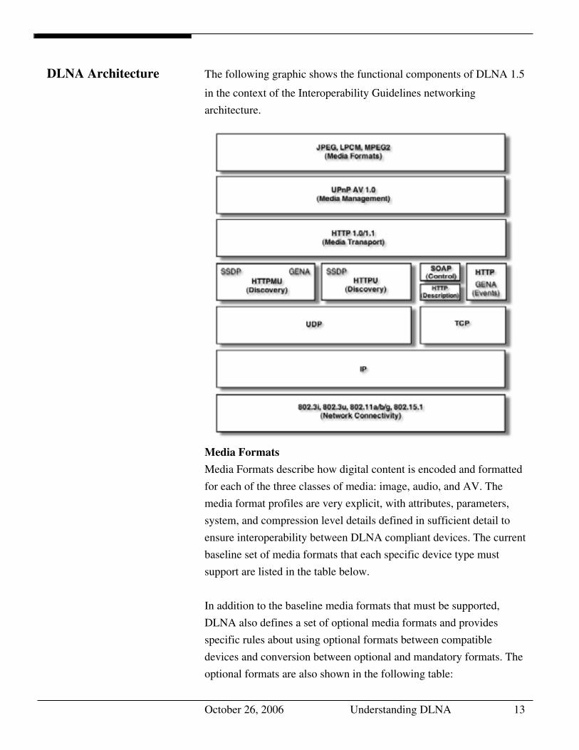
DLNA Architecture The following graphic shows the functional components of DLNA 1.5
in the context of the Interoperability Guidelines networking
architecture.
Media Formats
Media Formats describe how digital content is encoded and formatted
for each of the three classes of media: image, audio, and AV. The
media format profiles are very explicit, with attributes, parameters,
system, and compression level details defined in sufficient detail to
ensure interoperability between DLNA compliant devices. The current
baseline set of media formats that each specific device type must
support are listed in the table below.
In addition to the baseline media formats that must be supported,
DLNA also defines a set of optional media formats and provides
specific rules about using optional formats between compatible
devices and conversion between optional and mandatory formats. The
optional formats are also shown in the following table:
Understanding DLNA 14 Allegro Software Development Corporation
Media Class Mandatory Formats Optional Formats
Image JPEG PNG, GIF, TIFF
Audio LPCM AC3, AAC, MP3,
WMA9, ATRAC3plus
Video MPEG2 MPEG1, MPEG4,
VC1, MPV1
The focus on media formats is a dividing line between the work of the
UPnP Forum and DLNA. The UPnP Forum focused on achieving
device interoperability, which was accomplished. But the lack of
prescribed media profiles prevented the UPnP architecture from
delivering media interoperability and led to the founding of DLNA.
Media Transport
Media Transport defines how content moves across the network.
DLNA devices that send or receive any media content to/from the
network must support HTTP 1.1 (including chunked transfer encoding,
persistent connections, and pipelining) as the baseline transport
mechanism. In addition, Real-time Transport Protocol (RTP) is
available as an optional media transport protocol. But, the mandatory
requirement for HTTP 1.1 must always be met.
Media Management
Media management enables devices and applications to identify,
manage, and distribute digital media content across network devices.
The DLNA Guidelines incorporate the UPnP Forum AV and Printer
technology as the basis for DLNA media management. The services
provided by this technology are: Content Directory, Connection
Manager, AV Transport, and Rendering Control.
Content Directory
The Content Directory service provides a mechanism for each
content server on the network to provide a uniform directory of all
its available content to any interested devices on the network.
Every content server must have an instance of this service.
October 26, 2006 Understanding DLNA 15
This service might be used to display a list of songs stored on an
MP3 player, still-images comprising various slide shows stored on
a PC, movies stored in a DVD jukebox, TV shows currently being
broadcast by a Set-top Box, songs stored in a CD Jukebox, TV
programs that had been downloaded to a PVR, photos stored in a
digital camera, and many more. Nearly any type of content can be
listed via the Content Directory service, even for devices that
support multiple types of content. The information about the
content (metadata) returned by the Content Directory service
includes properties such as its name, artist, creation date, size, etc.
In addition, the metadata also indicates the transfer protocols and
data formats that are supported for each piece of content on the
server. This information is used by the Control Point to determine
if a given Media Renderer is capable of rendering the content in its
current format or if some type of transcoding is required.
Connection Manager
The Connection Manager service determines how the digital media
content can be transferred between two devices on the network.
Each device that sends or receives content must implement the
Connection Manager service. This service provides a mechanism
for devices to:
• Match capabilities between server and render devices.
• Set up and tear down connections between devices.
• Discover information about current transfers in the network.
When making connections, the Connection Manager service is the
interface between the devices and the TCP/IP stack.
AV Transport
The AV transport service enables control over the “playback” of
audio and video streams including the ability to Stop, Pause, Seek,
etc. This service type defines a common model for AV transport
control suitable for a generic user interface. It can be used to
control a wide variety of disc, tape, and solid-state media devices
such as CD players, VCRs, and MP3 players. Depending on the
Understanding DLNA 16 Allegro Software Development Corporation
supported transfer protocols and data formats, this service may or
may not be implemented.
Although most media will be sent across the network as data it
may be more efficient to transfer the media data stream using other
means. An example is when a personal video recorder is the media
source and a TV set is the media renderer (player). An Ethernet
connection would not be as efficient as an s-video connection.
Using a transfer medium that is not part of the TCP/IP network is
called an out of band transfer. These transfers are not defined by
the UPnP AV specification but are recommended and supported by
the manufacturer of the media equipment.
Rendering Control
Most rendering devices contain a number of dynamically
configurable attributes that affect how the current content is
rendered. For example, video devices, such as TVs, allow user
control of display characteristics such as brightness and contrast,
while audio devices allow control of audio characteristics such as
volume, balance, and equalizer settings. The Rendering Control
service is intended to provide control points with the ability to
query and/or adjust any rendering attribute that the device
supports.
The Rendering Control service enables a control point to:
• Discover the attributes supported by the device.
• Retrieve the current setting of any supported attribute.
• Change the setting of any modifiable attribute.
• Restore the settings defined by a named preset.
Device Discovery and Control
Device discovery and control enables a device on the home network to
discover the presence and capabilities of other devices on the network
and collaborate with these devices in a uniform and consistent manner.
DLNA incorporates the UPNP Forum Device Architecture 1.0 as the
basis for its device discovery and control.
October 26, 2006 Understanding DLNA 17
Discovery
Device discovery is the first step in UPnP networking. When a new
device is added to a network, the UPnP discovery protocol (SSDP)
allows the device to advertise its services to all control points on the
network via a multicast. Similarly, when a new control point is added
to the network, SSDP allows the control point to search for devices of
interest using a multicast. Thus, by listening to the standard multicast
address, control points and devices can be made aware of new services
being offered on the network and respond to service requests. In each
case, the response is a discovery message that contains a small number
of essential specifics about the device or its services, e.g., its UPnP
type, its universally unique identifier (UUID), and a URL to more
detailed information. When a control point discovers a new device or
service of interest – either as a result of a device’s advertisement or a
specific search – the control point must then use the URL in the
discovery message to retrieve a description of the device and its
capabilities.
Device Description
A UPnP device description includes vendor-specific manufacturer
information like the model name and number, serial number,
manufacturer name, URLs to vendor-specific Web sites, and a URL
for presentation. For each service included in the device, the device
description lists the service type, name, a URL for a service
description, a URL for control, and a URL for eventing. A device
description also includes a description of all embedded devices. Note
that a single physical device may include multiple logical devices. A
UPnP device description is written by the device vendor, and is
expressed in XML syntax and based on a standard UPnP Device
Template produced by the UPnP Forum working committee.
Understanding DLNA 18 Allegro Software Development Corporation
Service Description
A UPnP service description includes a list of commands, or actions,
the service responds to, and parameters, or arguments, for each action.
A service description also includes a list of variables. These variables
model the state of the service at run time, and are described in terms of
their data type, range, and event characteristics. Like a UPnP device
description, a UPnP service description is written by a UPnP vendor.
The description is in XML syntax and is based on the standard UPnP
Service Template.
Retrieving a UPnP device description is straight forward: the control
point issues an HTTP GET request on the URL in the discovery
message, and the device returns the device description. Retrieving a
UPnP service description is a similar process that uses a URL within
the device description.
Control
Once the device and its service descriptions are retrieved, a control
point can ask those services to invoke actions and the control point can
poll those services for the values of their state variables. Invoking
actions is a form of remote procedure call; a control point sends the
action to the device's service, and when the action has completed (or
failed), the service returns any results or errors. Polling for the value of
state variables is a special case of this scenario where the action and its
results are predefined.
To control a device, a control point invokes an action on the device's
service. To do this, a control point sends a suitable control message to
the control URL for the service (provided as part of the service
element in the device description). These messages are encapsulated in
SOAP, and sent via HTTP requests. In response, the service returns
any results or errors from the action – again using SOAP and HTTP.
The effects of the action, if any, may also be reflected by changes in
the variables that describe the run-time state of the service. When these
state variables change, events are published to all interested control
points.
October 26, 2006 Understanding DLNA 19
To determine the current value of a state variable, a control point may
poll the service. Similar to invoking an action, a control point sends a
suitable query message to the control URL for the service. In response,
the service provides the value of the variable; each service is
responsible for keeping its state table consistent so control points can
poll and receive meaningful values
As long as the discovery advertisements from a device have not
expired, a control point may assume that the device and its services are
available. If a device cancels its advertisements, a control point must
assume the device and its services are no longer available.
Eventing
As the section on Description explains, a UPnP service description
includes a list of actions the service responds to and a list of variables
that model the state of the service at run time. If one or more of these
state variables are evented, then the service publishes updates when
these variables change, and a control point may subscribe to receive
this information. Throughout this section, publisher refers to the
source of the events (typically a device's service), and subscriber
refers to the destination of events (typically a control point). Both
subscriber and publisher messages are delivered via a version of HTTP
that has been extended using General Event Notification Architecture
(GENA) methods and headers developed by the UPnP Forum.
To start receiving events, a subscriber sends a subscription message. If
the subscription is accepted, the publisher responds with a duration for
the subscription. To keep the subscription active, a subscriber must
renew its subscription before the subscription expires. When a
subscriber no longer needs eventing from a publisher, the subscriber
cancels its subscription.
The publisher notes changes to state variables by sending event
messages. Event messages contain the names of one of more state
variables and the current value of those variables, expressed in XML.
A special initial event message is sent when a subscriber first
subscribes; this event message contains the names and values for all
evented variables and allows the subscriber to initialize its model of
Understanding DLNA 20 Allegro Software Development Corporation
the state of the service. To support scenarios with multiple control
points, eventing is designed to keep all subscribers equally informed
about the effects of any action. Therefore, all subscribers are sent all
event messages, subscribers receive event messages for all evented
variables (not just some), and event messages are sent no matter why
the state variable changed (either in response to a requested action or
because the state the service is modeling changed). An example of this
would be the volume control on digital TV that was a DMP/DMR
combined device. Turning the physical volume control on the device
would send an event message to the network with the new volume
level. Conversely, a DMC could send a volume action to the TV that
would result in it changing its volume and sending an event message to
the network to that effect.
Some state variables may change value too rapidly for eventing to be
useful. One alternative is to filter, or moderate, the number of event
messages sent due to changes in a variable's value. Some state
variables may contain values too large for eventing to be useful; for
this, or other reasons, a service may designate one or more state
variables as non evented and never send event messages to subscribers.
To determine the current value for such non-evented variables, control
points must poll the service explicitly
Presentation
Presentation exposes an HTML-based user interface for
controlling/monitoring the status of a device. It augments the standard
UPnP control and eventing mechanisms by providing a browser based
avenue for sending actions to a device and receiving notification of
state changes from a device.
The URL for the presentation page is provided by the device
description. To retrieve the presentation page, an HTTP GET request
is issued to the presentation URL and the device returns the
presentation page. Loading the page into a browser will, provided the
page enables it, allow the user to control the device or view its status.
Unlike the interactions defined by the UPnP Device and Service
Templates, the capabilities of the presentation page are completely
October 26, 2006 Understanding DLNA 21
specified by the device vendor. The implementation details are also up
to the device vendor, but the use of an embedded web server in
conjunction with the device’s native capabilities is the most common
method of implementing this feature.
Network Stack
The basis for UPnP Networking (and thus DLNA) is the TCP/IP v4
protocol. Every device must implement a DHCP client, and search for
a DHCP server when first connected to the network. If a DHCP server
is discovered, the device must use the IP address assigned by the
server. If no DHCP server is discovered, the device must use Auto-IP
to generate a link-local IP address.
Auto-IP uses an implementation dependent algorithm to generate an
address in the 169.254/16 range. The first and last 256 addresses in
this range are reserved and must not be used. After developing an
address, the device must determine if the address is available by using
an ARP probe. If the device receives a response, the address is
assumed to be in use and the device must generate and test a new IP
address.
A device that has configured via Auto-IP must periodically check for
the presence of a DHCP server. If a DHCP server is discovered, the
device must switch to the IP address allocated to it by the DHCP
server. In order to switch between IP addresses, the device must cancel
any outstanding UPnP Discovery advertisements and re-issue them
under the new address.
In addition to IP addressing, UPnP makes extensive use of both the
UDP and TCP protocols. Discovery is done via an HTTP Multicast
over UDP and is used by devices to advertise their presence to the
network and by control points to discover what devices exist on the
network. Definition, control, and eventing services are delivered via
HTTP over TCP.
Understanding DLNA 22 Allegro Software Development Corporation
Network Connectivity
Three network connection technologies are incorporated in the DLNA
1.5 Interoperability Guidelines: 10Base-T and 100Base-T Ethernet
(802.3i / 802.3u) for wired connections, WiFi (802.11a /802.11b
/802.11g) for wireless connections, and Bluetooth for wireless
connections for mobile handheld devices such as cell phones and
PDAs. Additional network connections such as 1000Base-T Ethernet
(802.3ab) and faster WiFi (802.11n) will be added to the Guidelines in
the future. It should also be noted that many other networking
technologies such as LonWorks, CeBus, X-10, and Universal
Powerline Bus (UPB) could be supported via UPnP Bridges.
October 26, 2006 Understanding DLNA 23
Certification In order to ensure interoperability between DLNA devices, DLNA
developed and manages a comprehensive certification program.
Vendor products that successfully complete certification testing are
awarded the DLNA Certified Logo, which assures consumers that the
product is fully DLNA compliant and interoperates with other DLNA
Certified Logo products.
The initial step in gaining certification is for the products’ vendor to
subject the product to testing via DLNA’s Conformance Test Tool
(CTT). The CTT is a suite of tests that are run by the vendor against
the product, and validate the devices’ compliance with DLNA
standards. The test harness for the CTT is a single Windows PC with
the device under test connected via a DLNA defined network
connection technology (Ethernet, WiFi, Bluetooth). When the device
successfully passes the CTT as determined by the CTT’s log file, it
can begin the formal DLNA certification process.
The formal certification process entails submitting the CTT log and the
product’s UPnP certificate to DLNA, and scheduling a test session
with one of the Independent Certification Vendors (ICV) approved by
DLNA. The ICV will test the submitted product per DLNA’s
Certification Test Plan (CTP) against 3 reference devices of the
appropriate device class. For example, the ICV would test a DMP
device against 3 DMS reference devices, while a DMC would be
tested against 3 DMR and 3 DMS reference devices. Any device that
passes the CTP will be eligible for the DLNA Certification Logo.
Understanding DLNA 24 Allegro Software Development Corporation
In addition to its formal certification program, DLNA conducts
“plugfests” (interoperability workshops) on a regular basis. The
plugfests are held each calendar quarter in various locations around the
world in order to allow maximum participation from device vendors
across the globe. These plugfests provide DLNA member companies
the opportunity to test products under development against other
member’s products using DLNA test tools, and are an excellent dress
rehearsal for DLNA certification testing.
October 26, 2006 Understanding DLNA 25
About Allegro Allegro has been providing Internet solutions to systems vendors since
1996. We offer robust, standards compliant, portable implementations
of all major protocols including HTTP, XML and SOAP and our
customers include Agilent, Cisco, HP, Microsoft, Phillips, Siemens
and Xerox.
Allegro’s UPnP/DLNA technology development began more than 5
years ago, and we offer portable implementations that allow device
vendors to conform to the DLNA Interoperability Guidelines. Key
digital media players including Philips, Samsung, Roku, and Analog
Devices have selected Allegro’s UPnP/DLNA protocol stack for use in
their devices. In addition Microsoft has selected Allegro as the
supplier of UPnP/DLNA technology for its Media Center Extender
toolkit (PIKA) and a number of upcoming products.
Allegro is a regular participant at UPnP and DLNA plugfests and
Allegro’s extensive experience with UPnP/DLNA can help you design
and certify any DLNA device.
Questions about UPnP/DLNA? Give Allegro a call. We have the
answers!
Opinions expressed in this white paper are those of Allegro Software Development Corporation and are
not necessarily the official positions of the UPnP Forum or the Digital Living Network Alliance. For full
understanding of the UPnP Forum and the Digital Living Network Alliance please visit their web sites.
This white paper is © Copyright 2006 by Allegro Software Development Corporation. UPnP™ is a
certification mark of the UPnP Implementers Corporation. The names of other companies and products
mentioned herein are the trademarks of their respective owners.


![Protocol Specification · 2015-01-09 · 8th January 2015 SAT>IP Protocol Specification Page 5 of 70 SES S.A. References . UPnP Forum [1] UPnP Device Architecture 1.1 . DLNA [2] DLNA](https://img.pdfslide.net/doc/110x75/5f4bcb00c73ffb6385247baf/protocol-specification-2015-01-09-8th-january-2015-satip-protocol-specification.jpg)