Embed Size (px)
Citation preview

Uponor PEX-a Pipe Support
Commercial Piping Engineer Reference Guide
U.S. REFERENCE GUIDE
C O M M E R C I A L P I P I N G S Y S T E M S
Uponor crosslinked polyethylene (PEX-a) pipe and ProPEX® expansion fittings offer value, durability and performance to your commercial plumbing and hydronic distribution piping projects. With more than 40 years of service in
installations around the world, Uponor products and systems, which are proudly made in the U.S.A., are the proven solution that professionals require to meet the demands of the commercial building industry.
This reference guide is designed for architects, building officials, engineers and mechanical contractors interested in Uponor Commercial Piping Systems. It describes general installation recommendations that use Uponor PEX-a pipe and ProPEX fitting products. Uponor is not liable for installation practices that deviate from this guide or are not acceptable practices within the mechanical trades, codes or standards of practice. Always refer to local codes for additional requirements. For further assistance, refer to the Uponor Plumbing Design Assistance Manual (PDAM), Uponor Complete Design Assistance Manual (CDAM) or contact Uponor Technical Services at 888.594.7726 or [email protected].
Uponor maintains standard-grade ratings for Uponor PEX-a pipe as tested in accordance with PPI TR-3. Uponor PEX-a products have the following temperature and pressure ratings:
• 200°F at 80 psi
• 180°F at 100 psi
• 73.4°F at 160 psi
Excessive Short-term Temperature - Pressure Capacity:
• 210°F at 150 psi tested up to 720 hours
• In accordance with Section 6.6 of ASTM F876, the minimum hydrostatic burst pressure for 1⁄2" pipe is 480 psi at 73.4°F. For 3⁄4" pipe and larger, the minimum burst pressure is 475 psi at 73.4°F.
Uponor’s quality lab performs daily burst pressure testing on all pipe sizes above and beyond the ASTM F876 standard. All samples are tested at 73.4°F and burst at an elevated pressure of 800 psi (+/- 20 psi) — nearly twice the pressure requirement of ASTM F876.
Hydrostatic Temperature and Pressure Ratings
Uponor Crosslinked Polyethylene (PEX-a) Pipe The Core of Uponor Piping Systems
1

Not All PEX is Created Equal
Uponor PEX-a
• Most tested and third-party listed of all PEX
• Highest degree of crosslinking (>80%)
• “Hot” crosslinking above the crystal melting temperature
• Most flexible of all PEX and allows kink reparability
• Shape memory ideal for cold-expansion ProPEX fittings
• Increased resistance to corrosion
PEX-b
• Lowest degree of crosslinking (65-70%)
• Crosslinking performed in a secondary, post-extrusion process
• Stiffer product
• No kink reparability
• Not ideal for cold-expansion fittings
• Standard insert fittings have less flow
PEX-c
• Lesser degree of crosslinking (70-75%)
• “Cold” crosslinking below the crystal melting temperature
• Less uniform, less consistent
• Stiffer product
• No kink reparability
• Not ideal for cold-expansion fittings
• Standard insert fittings have less flow
Uponor PEX-a vs. Copper, CPVC, Black Iron Pipe (BIP) and Polypropylene Random (PP-R)
Pipe Comparisons PEX-a Copper CPVC BIP PP-R
Flexible, fewer required connections, reduces potential leak liability Yes No No No No
Expands up to 3X its diameter to help resist freeze damage Yes No No No No
Manufactured fitting connection, cannot be dry fit Yes No No No Yes
One simple tool for connections Yes No No No No
Resists corrosion, pitting and scaling Yes No Yes No Yes
Dampens rushing water noise, eliminates water hammer Yes No Yes No Yes
Retains more heat in hot water lines Yes No Yes No Yes
Less susceptible to condensation on cold-water lines Yes No Yes No Yes
Stable material costs; eliminates jobsite theft concerns Yes No Yes Yes Yes
Pipe and fittings warranty Yes No Yes No Yes
Uponor PEX-a CPVC Black Iron Pipe (BIP) Polypropylene Random (PP-R)Copper
2

greater flow2
Double70%
the wall thickness1
and
1 When comparing 1 ⁄2" F1960 with F1807 brass fittings 2 When comparing 1" F1960 engineered polymer (EP) with F2159 plastic fittings
ProPEX Fittings vs. Standard Insert Fittings
Uponor ProPEX Cold Expansion Fitting Standard Insert Fitting
ASTM F1960 Brass ASTM F1960 EP ASTM F1807 Brass ASTM F2159 Plastic
A Wall thickness
1⁄2" 0.057" 0.057" 0.028" 0.056"
3⁄4" 0.057" 0.057" 0.037" 0.082"
1" 0.072" 0.072" 0.041" 0.100"
B Flow path 1⁄2"
0.112 sq. inches 2.8 gpm @ 8 ft./sec. 4.2 gpm @ 12 ft./sec.
0.116 sq. inches 2.9 gpm @ 8 ft./sec. 4.4 gpm @ 12 ft./sec.
0.096 sq. inches 2.4 gpm @ 8 ft./sec. 3.6 gpm @ 12 ft./sec.
0.078 sq. inches 1.9 gpm @ 8 ft./sec. 2.9 gpm @ 12 ft./sec.
3⁄4"0.278 sq. inches 6.9 gpm @ 8 ft./sec. 10.4 gpm @ 12 ft./sec.
0.273 sq. inches 6.8 gpm @ 8 ft./sec. 10.2 gpm @ 12 ft./sec.
0.221 sq. inches 5.5 gpm @ 8 ft./sec. 8.3 gpm @ 12 ft.sec.
0.166 sq. inches 4.1 gpm @ 8 ft./sec. 6.2 gpm @ 12 ft./sec.
1"0.496 sq. inches 12.4 gpm @ 8 ft./sec. 18.6 gpm @ 12 ft./sec.
0.488 sq. inches 12.2 gpm @ 8 ft./sec. 18.2 gpm @ 12 ft./sec.
0.396 sq. inches 9.9 gpm @ 8 ft./sec. 14.8 gpm @ 12 ft./sec.
0.292 sq. inches 7.3 gpm @ 8 ft./sec. 10.9 gpm @ 12 ft./sec.
C Internal diameter
1⁄2" 0.378" 0.385" 0.350" 0.315"
3⁄4" 0.595" 0.590" 0.530" 0.460"
1" 0.795" 0.788" 0.710" 0.610"
Minimum Distance Between ProPEX Fittings
Nominal Fitting Size Cut Length of Pipe
1⁄2" 21⁄2"
3⁄4" 31⁄2"
1" 41⁄2"
11⁄4" 51⁄2"
11⁄2" 61⁄2"
2" 71⁄2"
Commercial EP Multiport Tee ProPEX EP Elbow
ProPEX EP Tee
A
B
C
D
WIRSBO COMPANYCAD GENERATED DRAWING,DO NOT MANUALLY UPDATE
SCALE
SIZE
CAD FILE:
PART NO.
A
SHEET OF
REV.
APPROVALS DATE
DRAWN BY
APPROVED BY
UNLESS OTHERWISE SPECIFIEDDIMENSIONS ARE IN INCHESTOLERANCES ARE:
MATERIAL
BRASS
DO NOT SCALE DRAWING
2345678
Q&E/ProPEX Brass Tee,1/2" PEX x 1/2" PEX x 1/2" PEX
A
B
C
D
2345678
5925 148TH STREET WESTAPPLE VALLEY, MN 55124
PHONE (952) 891 - 2000 FAX (952) 891 - 1246
Q4705050 AIQ4705050-
LLZ 01/23/04
REVISIONS
LETTER ECO # DATE
THE INFORMATION CONTAINED IN THISDRAWING IS THE SOLE PROPERTY OF UPONOR WIRSBO. ANY REPRODUCTIONIN PART OR WHOLE WITHOUT THE WRITTEN PERMISSION OF UPONORWIRSBO IS PROHIBITED.
ANGLES ± 1 ∞
.X ± .06
.XX ± .01
.XXX ± .005
SURFACE FINISH UNLESSOTHERWISE SPECIFIED:
125
250
250
MACH./ MOLDED
OTHERDRILLED
AD 05/29/01WAV10082
AE 12/12/02APV20031
AF 01/23/04APV20325
AG 03/22/04APV20380
AH 06/28/04APV20443
AI APV20505 10/12/04
KLC 10/12/04
3x R .02
1/2" 1/2"
1/2"
3x Q1110501-AA
B
B
R .438 - .010+ .060
6x 30∞
6x .200 ±.020
A
A
1.01 REF.
2.52 REF.
3x ÿ .398 REF.
1.10 ±.02
6x 30∞.157 - .010+ .060
SECTION A-A
NOTES:
1. RADIUS ALL CORNERS .005-.015, UNLESS OTHERWISE SPECIFIED
2. MAXIMUM CUT-OFF BURR .010.
ÿ .60.60 REF.
.60 - .01+ .06
SECTION B-B
Markings DetailMARKING BOARD TEXT
EXTEND .008 REF.
AI
.42 REF.
.68 REF.
.32 REF.
.24 REF.
DETAIL BOTH SIDES MARKINGS
C
NOTES:
1. RADIUS ALL CORNERS .005 - .015, UNLESS OTHERWISE SPECIFIED
2. REGRIND NOT ALLOWED AC
A
B
C
D
WIRSBO COMPANYCAD GENERATED DRAWING,DO NOT MANUALLY UPDATE
SCALE
SIZE
CAD FILE:
PART NO.
A
SHEET OF
REV.
APPROVALS DATE
DRAWN BY
APPROVED BY
UNLESS OTHERWISE SPECIFIEDDIMENSIONS ARE IN INCHESTOLERANCES ARE:
MATERIALACUDEL 22000BK937
DO NOT SCALE DRAWING
2345678
A
B
C
D
2345678
5925 148TH STREET WESTAPPLE VALLEY, MN 55124
PHONE (952) 891 - 2000 FAX (952) 891 - 1246
P4755050 ACP4755050
ALP 07/21/05
REVISIONS
LETTER ECO # DATE
THE INFORMATION CONTAINED IN THISDRAWING IS THE SOLE PROPERTY OF UPONOR WIRSBO. ANY REPRODUCTIONIN PART OR WHOLE WITHOUT THE WRITTEN PERMISSION OF UPONORWIRSBO IS PROHIBITED.
ANGLES ± 1 ∞
.X ± .06
.XX ± .01
.XXX ± .005
SURFACE FINISH UNLESSOTHERWISE SPECIFIED:
125
250
250
MACH./ MOLDED
OTHERDRILLED
SSC EP TEE,1/2" PEX x 1/2" PEX x 1/2" PEX
-
AA NO PRINT
AB APV20650 08/10/05
AC APV20718 09/06/06
LDH 09/11/06
2x R.050
3x P1110502-AA
SECTION A-A
3x .04
2.3 REF
ÿ .485 ±.010
BACK SIDE MARKINGSDETAIL
"Supplier ID" "Countryof Origin"
"Date Code"
C
A - Wall thickness
B - Flow path
C - Internal
diameter
ProPEX F1960 Expansion Fitting
F1807/F2159 Insert Fitting
ProPEX Transition Fittings
3

Uponor PEX-a Codes and Standards
Codes: IMC, IPC, IRC, NSPC, UMC, UPC
Listings: AWWA, HUD, IAPMO, ICC, Intertek, ITS, NSF, NSF-pw, NSF-rcw, NSF-rfh, PHCC, PPI, QAI, UL
Standards: ASTM E84, ASTM E814, ASTM E119, ASTM F876, ASTM F877, ASTM F2023, ASTM F1960, ASTM F2657, ANSI/NSF 14 and 61
Fire-rated Assemblies: Tested in accordance with ASTM E119/UL 263; G573, K913, L557, U372, V444
Uponor PEX-a pipe products are approved for installation in return-air plenums as described below. All Uponor PEX-a pipe, Uponor ProPEX Rings and Uponor engineered polymer (EP) fittings were tested and approved.
½" to ¾" Uponor PEX-a (Un-insulated) Adjacent runs of un-insulated ½" to ¾" Uponor PEX-a pipe in a return-air plenum must be separated by 18". Larger pipe sizes are not approved for use without ½" fiberglass insulation unless the pipe is supported with a minimum of 48" of Uponor PEX-a Pipe Support with a maximum distance of 10" between pipe support pieces.
Classified as to Surface Burning Characteristics
ASTM E84 Flame Spread Smoke Developed
Nominal ½" to ¾" size
25 or less 50 or less
Up to 2" Uponor PEX-a Supported with Uponor PEX-a Pipe Support (Un-insulated) Uponor PEX-a manufactured with a maximum outside diameter (OD) of 2" nominal pipe size supported with a minimum length of 48" Uponor PEX-a Pipe Support, and a maximum distance of 10" between pipe support pieces. PEX-a Pipe Support shall terminate a maximum of 5" away from the centerline of the adjacent fitting. There are no spacing requirements between adjacent runs of this pipe.
Classified as to Surface Burning Characteristics
ASTM E84 Flame Spread Smoke Developed
Up to 2" Uponor PEX-a Supported with Uponor PEX-a Pipe Support
0 20
Up to 3" Uponor PEX-a (Insulated) Uponor PEX-a manufactured with a maximum OD of 3" nominal pipe size (NPS) and encased in ½" fiberglass insulation shall have no limitation on spacing. This applies to piping runs with or without Uponor EP fittings.
Classified as to Surface Burning Characteristics
ASTM E84 Flame Spread Smoke Developed
Up to 3" Uponor PEX-a with ½" insulation
0 35 or less
Per UL fire-resistance classifications and follow-up service inspections, ongoing verification of product compliance is achieved through quarterly inspection audits at manufacturing location(s) during which a review of the product’s process, suppliers and in-house quality control procedure is conducted. This audit ensures the product has not changed since the ASTM E84 testing was conducted and will still meet the requisite standards.
Plenum Listings
Uponor PEX-a Pipe Support
4

Non-rated wall or non-load bearing wall assembly with Uponor AquaPEX® pipe installed per ANSI/UL 263 (ASTM E119, NFPA No. 251) (refer to UL Design No. V444)
Uponor AquaPEX pipe riserMid-story guide (see riser detail on page 6)
Riser clamp (see riser detail on page 6)
Firestop listed to ASTM E814 (must be Uponor AquaPEX pipe compatible)
ANSI/UL 263 slab listed with Uponor AquaPEX pipe only (refer to UL Design No. K913)
Maximum pipe density is 13 cubic inches with or without sleeve per one cubic foot of concrete (equivalent of 3" average spacing through slab between ½" Uponor AquaPEX pipe); utility-grade polyethylene sleeve ¾" to 1" nominal pipe or PVC conduit 1" to 1¼" nominal and ½" to 2" Uponor AquaPEX pipe
For ANSI/UL 263 steel-stud rated walls maximum Uponor AquaPEX pipe of 1.3 lbs./ft. and not to exceed total weight per stud cavity of 8.0 lbs.
Copper manifold or Uponor EP multiport tee with a weight not exceeding 1.0 lbs. per cavity (typical)
Uponor PEX one or five-loop stand-up bracket or metal/2x4 wood pre-drilled mounting bracket on top side of slab
6½" minimum restrained or un-restrained
Structural rebar (two layers)
Concrete Floor/Ceiling Assembly (UL Design No. K913)Steel-stud Wall Assembly (UL Design No. V444)
Steel stud
Fire-resistant Construction Ratings
ASTM E119 and ANSI/UL 263
Construction Type
Assembly Type
UL Design No.
Non-combustible Concrete/Steel Construction
Floor/CeilingK913G573
Walls V444
Wood Frame Construction
Floor/Ceiling L557
Walls U372
Expansion and Contraction
Because PEX pipe expands at a rate of 1.1" per 100' per 10°F temperature rise, an expansion joint, offset or change in direction is necessary to accommodate the expansion and contraction of the
pipe. Uponor offers a preformed 2" Uponor AquaPEX Expansion Joint (F8152000) and 2" Wirsbo hePEX Expansion Joint (A1992000) to make expansion joint installations more efficient.
2" Uponor PEX-a Expansion Joint
Risers
Risers typically feature Uponor PEX-a pipe in sizes from 1¼" to 2" with CTS riser clamps at the base of each floor.
The installation should also include a riser clamp at the top of every-other story for plumbing and every story for hydronic distribution to limit the expansion and contraction of the pipe. This translates to an expansion of about 1½" in 25' at a 60°F Delta T (installed at 60°F with an operating temperature of 120°F).
In this application, the piping will snake slightly in areas where it is not constrained, requiring the use of mid-story guides. Use discarded framing as a backer plate for the guide. Ensure the guide has no sharp edges or is fire-rated for risers in walls requiring fire-resistant construction.
Through Penetrant Firestop
The following firestop manufacturers offer PEX solutions as tested in accordance with ASTM E814.
• 3MTM
• Hilti®
• HoldRite® HydroFlameTM
• Metacaulk®
• Passive Fire Protection Partners
• ProSet Systems®
• Tremco®
See firestop manufacturer’s website for selection of appropriate fire assembly and product.
5

Use appropriate floorassembly per code
Overhead plumbing distribution
ProPEX EP tee
Branch piping isolation valve
Plastic grommet required if pentrating steel stud
EP multiport tee
Uponor AquaPEX® pipe risers
Appropriate firestop material (must be Uponor AquaPEX compatible)
Mid-story guide required between each floor
Fixture termination rough-in assembly
Riser clamp required at the base of each floor
Wall-framing member
Refer to appropriate fire assembly listing for penetration requirements
Pre-sleeved Uponor AquaPEX
In-slab plumbing distribution
Riser clamp required at the top of every-other floor to limit expansion and contraction to 25'
Use appropriate wallassembly per code
Plumbing Riser Detail
6

ProPEX EP tee
Riser clamp required at the top of each floor
Riser clamp required at the top of each floor
Riser clamp required at the base of each floor
Riser clamp required at the top of each floor
Riser clamp required at the base of each floor
Refer to appropriate fire assembly listing for penetration requirements
ProPEX EP tee
Plastic bend support
Plastic bend support
ProPEX transition fitting for valve assembly
Fan Coil Unit (FCU)
Fan Coil Unit (FCU)
Note: Other terminal units, such as heat pumps, radiators,VAV boxes and chilled beams can be supplied through similar means.
Fan Coil Unit (FCU)
Wirsbo hePEXTM hot and chilled water supply and return risers
Appropriate firestop material (must be Wirsbo hePEX compatible)
Mid-story guide required between each floor
Wall-framing member
Mid-story guide required between each floor
Use appropriate wall assembly per code
Hydronic Distribution Piping Riser Detail
7

Beam Clamp
Threaded Rod
18"Max. 6' or 8' spacing between suspendedsupports
Max. cantilever distance
48"Max. distance for unsupported PEX-a pipe
18"Max. support distance from fitting
1"
Min. 1" extension past support
Pipe support trapeze
Point of last support
Strapping requirements
Steel Joist
Suspended Piping Installation Detail
For suspended runs of piping, Uponor PEX-a can be supported by the same conventional means as metallic pipe using copper tube size (CTS) pipe hangers or supports.
Uponor recommends using hangers and supports designed for use with plastic pipe. Use PEX-a pipe support or pipe support channel that continuously supports the pipe to achieve nearly the same support spacing as copper pipe.
Suspended piping should be supported at intervals not to exceed 6' for ½" and ¾" pipe; 8' for 1" to 2" pipe.
Maximum distance from clamp/hanger to end of PEX-a Pipe Support is 18".
Maximum Distance Between PEX-a Pipe Supports
Application Maximum Distance
Non-plenum ½" to 1" pipe 1¼" to 2" pipe
32" for IPC/UPC/NPC32" for IPC/NPC48" for UPC
ASTM E84 Plenum 10"
Strapping Requirements for Clamps and Hanger Applications
Application Maximum Distance
Clamps Greater than 48" = 1 tie mid-span
Hangers Less than 48" = 2 ties equally spaced Greater than 48" = 3 ties (1 mid-span and 1 on each end placed 2" from end of support)
Important! For ASTM E84 plenum applications only, PEX-a Pipe Support sections shall be no less than 48". To view the ASTM E84 listing for Uponor PEX-a Pipe Support in plenum applications, see listing number P321-2 on www.qai.org.
Minimum Distance from Fitting-end of ProPEX Ring to PEX-a Pipe Support
Pipe Size Minimum Distance
½" 1¼"
¾" 1¾"
1" 2¼"
1¼" 2¾"
1½" 3"
2" 4"
Overlapping PEX-a Pipe Support is permitted with the following guidelines:
• Min. 6" overlap
• Min. two (2) 50-lb. cable ties at the overlap
• Hanger required within 18" of the overlap end
For more information regarding support solutions, contact Uponor Technical Services at 888.594.7726 or [email protected].
Note: If installing in a plenum, the maximum distance for exposed pipe/EP fittings between PEX-a pipe supports or insulation is 10".
8
Beam Clamp
Threaded Rod
18"Max. 6' or 8' spacing between suspendedsupports
Max. cantilever distance
48"Max. distance for unsupported PEX-a pipe
18"Max. support distance from fitting
1"
Min. 1" extension past support
Pipe support trapeze
Point of last support
Strapping requirements
Steel Joist
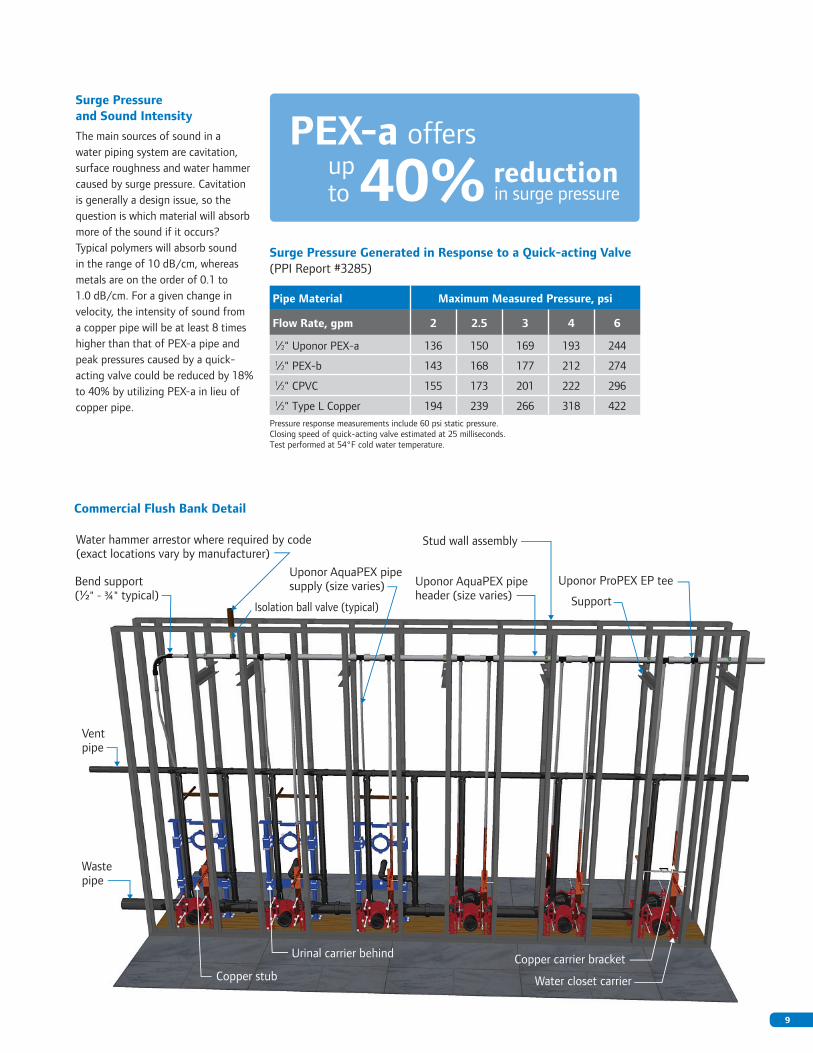
Water hammer arrestor where required by code (exact locations vary by manufacturer)
Isolation ball valve (typical)
Bend support(½" - ¾" typical)
Vent pipe
Wastepipe
Urinal carrier behind
Copper stub
Uponor AquaPEX pipeheader (size varies)
Stud wall assembly
Uponor ProPEX EP tee
Support
Uponor AquaPEX pipe supply (size varies)
Copper carrier bracket
Water closet carrier
Commercial Flush Bank Detail
Surge Pressure Generated in Response to a Quick-acting Valve (PPI Report #3285)
Pipe Material Maximum Measured Pressure, psi
Flow Rate, gpm 2 2.5 3 4 6
1⁄2" Uponor PEX-a 136 150 169 193 2441⁄2" PEX-b 143 168 177 212 2741⁄2" CPVC 155 173 201 222 2961⁄2" Type L Copper 194 239 266 318 422
Pressure response measurements include 60 psi static pressure. Closing speed of quick-acting valve estimated at 25 milliseconds. Test performed at 54°F cold water temperature.
Surge Pressure and Sound Intensity
The main sources of sound in a water piping system are cavitation, surface roughness and water hammer caused by surge pressure. Cavitation is generally a design issue, so the question is which material will absorb more of the sound if it occurs? Typical polymers will absorb sound in the range of 10 dB/cm, whereas metals are on the order of 0.1 to 1.0 dB/cm. For a given change in velocity, the intensity of sound from a copper pipe will be at least 8 times higher than that of PEX-a pipe and peak pressures caused by a quick-acting valve could be reduced by 18% to 40% by utilizing PEX-a in lieu of copper pipe.
PEX-a offers
40%up to in surge pressure
reduction
9

Uponor Logic
Number of Fittings 9
Number of Connections 33
Nominal Pipe Size Length (ft)
1⁄2" 261
3⁄4" 38
1" 5
Total 304
Home Run
Number of Fittings 7
Number of Connections 27
Nominal Pipe Size Length (ft)
1⁄2" 475
3⁄4" 30
1" 5
Total 510
Uponor Logic Plumbing
Uponor Logic is the smart way to plumb, using flexible PEX-a pipe and multiport tees to minimize connections and maximize system performance. With an Uponor Logic layout, plumbing systems typically require fewer fittings than a trunk and branch design and less tubing than a home run layout.
Critical Path = HWS - W.H. to Tub UPC Tub = 4 wsfu = 4 gpm CWS = 60°F HWS = 120°F Mixed = 110°F Hot-water Multiplier = 0.83 = 3.32 gpm
System Type
I.D. (in.) Distance (ft.) Volume (gal.) Velocity (ft./sec.)
Pressure Loss (psi) HW Time-to-fixture
1⁄2" 3⁄4" 1⁄2" 3⁄4" 1⁄2" 3⁄4" Total 1⁄2" 3⁄4" 1⁄2" 3⁄4" Total Critical Path - Tub Only
Copper T & B 0.527 0.745 13 33 0.147 0.746 0.893 4.8 2.43 1.22 0.561 1.781 16.1 sec.
Home Run 0.475 0.671 32 9 0.294 0.165 0.459 5.8 3 4.16 0.252 4.412 8.3 sec.
Uponor Logic 0.475 0.671 19 17 0.174 0.312 0.486 5.8 3 2.47 0.476 2.946 8.7 sec.
1 0
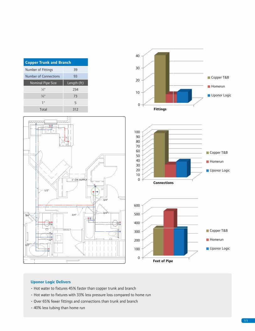
Copper Trunk and Branch
Number of Fittings 39
Number of Connections 93
Nominal Pipe Size Length (ft)
1⁄2" 234
3⁄4" 73
1" 5
Total 3120
10
20
30
40
Fittings
Copper T&B
Homerun
Uponor Logic
0 10 20 30 40 50 60 70 80 90
100
Connections
0
100
200
300
400
500
600
Feet of Pipe
Copper T&B
Homerun
Uponor Logic
Copper T&B
Homerun
Uponor Logic
Uponor Logic Delivers
• Hot water to fixtures 45% faster than copper trunk and branch
• Hot water to fixtures with 33% less pressure loss compared to home run
• Over 65% fewer fittings and connections than trunk and branch
• 40% less tubing than home run
1 1

Pressure Loss (psi) per 100 Feet of Uponor AquaPEX Pipe at 60°F
100.010.01.00.1
Pressure Loss (psi)
1000.0
200.0
20.0
2.0
0.2
Flow
Rat
e (g
pm)
2" PEX Tubing Velocity 2 ft./second
11/2" PEX Tubing
11/4 " PEX Tubing
1" PEX Tubing
3/4 " PEX Tubing
1/2" PEX Tubing
3/8 " PEX Tubing
Velocity 4 ft./second
Velocity 3 ft./secondVelocity 5 ft./second
Velocity 6 ft./second
Velocity 7 ft./second
Velocity 8 ft./second
Velocity 9 ft./second
Velocity 10 ft./second
Velocity 11 ft./second
Velocity 12 ft./second
3" PEX Tubing
Pipe Sizing an Uponor AquaPEX Plumbing System
Uponor recommends using the uniform friction loss method of pipe sizing. After determining the system’s friction loss (psi/100 ft.) by performing a building supply water calculation, develop a water size chart for each system’s water temperature and pipe size. To do this, reference the Uponor AquaPEX flow charts on Uponorpro.com and convert the gallons per minute (gpm) to fixture
units for each nominal pipe size or use Uponor’s Pipe Sizing Calculator at www.uponorpro.com/calculator. Per manufacturer’s recommendations, Uponor allows the dedicated fixture supply pipe to be of the same nominal size as the fixture being supplied, provided the dedicated pipe is no longer than 20 linear feet from a uniform friction loss-sized pipe.
www.uponorpro.com/calculator
Note: Maximum velocity through Uponor AquaPEX systems shall be 12 ft./sec. Uponor recommends not exceeding 10 ft./sec. for cold and 8 ft./sec. for hot domestic water systems. Contact Uponor Technical Services at 888.594.7726 or [email protected] to determine the maximum velocities based on the use, geographical region and intended operating conditions for your specific project.
1 2

Pre-insulated AquaPEX R-value/Heat Loss1
Pipe Size R-value Heat Loss at 70°F ΔT1⁄2" 3.3 8.9 Btu/(hr•ft²•°F)
3⁄4" 3.1 11.1 Btu/(hr•ft²•°F)
1" 3.0 13.1 Btu/(hr•ft²•°F)
11⁄4" 2.9 15.2 Btu/(hr•ft²•°F)
11⁄2" 2.8 17.1 Btu/(hr•ft²•°F)
2" 2.7 21.0 Btu/(hr•ft²•°F)1 Pre-insulated Uponor AquaPEX consists of PEX-a pipe and closed cell,
crosslinked polyethylene insulation with a thermal conductivity of 0.25 Btu•in/(hr•ft2•°F).
Thermal Conductivity
PEX-a pipe has a very low coefficient of thermal conductivity, 2.628 Btu•in/(hr•ft²•°F), whereas copper has a coefficient of thermal conductivity between 2080 and 2773 Btu•in/(hr•ft²•°F) depending on wall thickness (Type K, L or M). Therefore, PEX-a pipe does not sweat like copper does. PEX-a has superior insulative qualities when compared to copper in the same application. Even though the difference in R-Value is relatively small, the higher R-Value
with a PEX-a pipe will always result in less heat loss when compared to the same nominal size copper pipe. Uponor recommends insulating all return piping as well as any hydronic distribution piping (heating/chilled) to conserve energy and maintain desired fluid temperature. Uponor also recommends insulating any piping installed in an unconditioned space or poorly ventilated areas with excessive moisture content.
Pre-insulated Uponor AquaPEX is available in:
• 1⁄2"-2" pipe sizes with 1⁄2" PEX-foam insulation• 3⁄4"-3" pipe sizes with 1" PEX-foam insulation
(special order)
PEX-a pipe offersheat loss compared to uninsulated copper pipe
Uninsulated 21% less
PEX-a vs. Copper Heat Loss Comparison — Btu • in/(h • ft² • °F)
Delta T (°F) 20 40 60 80 100
Insulation Thickness (K=0.24)
0" 1⁄2" 1" 11⁄2" 0" 1⁄2" 1" 11⁄2" 0" 1⁄2" 1" 11⁄2" 0" 1⁄2" 1" 11⁄2" 0" 1⁄2" 1" 11⁄2"
Nom
inal
Pip
e Si
zes
1⁄2"Uponor PEX-a 5.44 2.22 1.63 1.37 10.89 4.44 3.25 2.74 16.33 6.65 4.88 4.10 21.78 8.87 6.51 5.47 27.22 11.09 8.13 6.84
Type L Copper 5.76 2.24 1.63 1.37 11.52 4.47 3.27 2.74 17.27 6.71 4.90 4.11 23.03 8.95 6.53 5.48 28.79 11.18 8.16 6.85
3⁄4"Uponor PEX-a 7.48 2.73 1.95 1.61 14.96 5.47 3.89 3.21 22.44 8.20 5.84 4.82 29.92 10.94 7.78 6.43 37.40 13.67 9.73 8.03
Type L Copper 8.06 2.77 1.96 1.61 16.12 5.54 3.91 3.22 24.18 8.31 5.87 4.84 32.25 11.07 7.83 6.45 40.31 13.84 9.78 8.06
1"Uponor PEX-a 9.42 3.23 2.25 1.83 18.85 6.47 4.50 3.66 28.27 9.70 6.75 5.49 37.69 12.93 8.99 7.33 47.11 16.17 11.24 9.16
Type L Copper 10.36 3.29 2.27 1.84 20.73 6.58 4.53 3.68 31.09 9.86 6.80 5.52 41.46 13.15 9.06 7.36 51.82 16.44 11.33 9.20
11⁄4"Uponor PEX-a 11.29 3.72 2.54 2.05 22.58 7.44 5.08 4.09 33.87 11.16 7.63 6.14 45.16 14.88 10.17 8.19 56.45 18.60 12.71 10.24
Type L Copper 12.67 3.80 2.57 2.06 25.34 7.60 5.14 4.12 38.00 11.40 7.70 6.18 50.67 15.20 10.27 8.24 63.34 19.00 12.84 10.30
11⁄2"Uponor PEX-a 13.08 4.20 2.83 2.26 26.15 8.40 5.66 4.51 39.23 12.60 8.49 6.77 52.30 16.79 11.31 9.03 65.38 20.99 14.14 11.28
Type L Copper 14.97 4.31 2.86 2.27 29.94 8.61 5.73 4.55 44.91 12.92 8.59 6.82 59.89 17.23 11.45 9.10 74.86 21.53 14.32 11.37
2"Uponor PEX-a 16.46 5.13 3.39 2.66 32.93 10.27 6.77 5.33 49.39 15.40 10.16 7.99 65.85 20.54 13.55 10.65 82.31 25.67 16.94 13.32
Type L Copper 19.58 5.31 3.45 2.69 39.16 10.63 6.89 5.38 58.73 15.94 10.34 8.08 78.31 21.25 13.78 10.77 97.89 26.57 17.23 13.46
3"Uponor PEX-a 22.54 6.94 4.47 3.44 45.07 13.88 8.93 6.89 67.61 20.82 13.40 10.33 90.14 27.76 17.86 13.77 112.68 34.70 22.33 17.22
Type L Copper 28.79 7.31 4.59 3.50 57.58 14.62 9.17 7.01 86.37 21.93 13.76 10.51 115.16 29.24 18.35 14.01 143.95 36.55 22.93 17.51
All calculations based on cylindrical thermal resistance methodology (ASPE/ASHRAE)
Based on fluid velocity of 8 ft./sec. at 160°F (maximizing heat transfer from 100% water)
Pipe convection set to be 1.761 Btu/hr•ft²•°F (based on standard value for free convection of air)
This heat loss comparison uses 0.24 Btu•in/(hr•ft2•°F) as the insulation thermal conductivity. This is a standard value for fiberglass pipe insulation at a 100°F mean temperature.
1 3

Pipe Sizing a PEX-a Hydronic Distribution System
Wirsbo hePEX tubing is sized using the Darcy Wiesbach friction factor methodology. Sizing with this method allows for accurate calculation of head loss based on the internal roughness of Uponor’s PEX-a pipe. The hydronic distribution pipe sizing tables on this page yield typical flow and BTU ranges based on specified pipe size, minimum velocity, maximum velocity, fluid type, fluid temperature, temperature differential (supply vs. return) and maximum head loss per 100 ft. of piping. Uponor’s online hydronic sizing
calculator is capable of generating flow tables for four-pipe hydronic distribution systems based on user specified inputs similar to the inputs used to create the tables on this page. This calculator allows the engineer/user to create easy-to-use tables that will accurately assist in system design.
www.uponorpro.com/calculator
Wirsbo hePEX Hydronic Sizing Table — Heating (20°F ΔT)
100% Water at 160°F — 4 ft. of Head Loss/100 ft. — Min. Velocity = 1.5 ft./sec. — Max. Velocity = 5.5 ft./sec.
Pipe Size BTU Range GPM Range Velocity (ft./sec.) Feet of Head per 100 ft. of Pipe
1⁄2" 8,300 − 11,000 0.83 − 1.10 1.50 − 2.00 2.53 − 4.00
5⁄8" 12,100 − 18,600 1.21 − 1.86 1.50 − 2.30 1.99 − 4.00
3⁄4" 15,500 − 27,600 1.65 − 2.76 1.50 − 2.50 1.64 − 4.00
1" 27,300 − 54,600 2.73 − 5.46 1.50 − 3.00 1.20 − 4.00
1 1⁄4" 40,800 − 92,500 4.08 − 9.25 1.50 − 3.40 0.94 − 4.00
1 1⁄2" 56,800 − 147,800 5.68 − 14.78 1.50 − 3.90 0.76 − 4.00
2" 97,500 − 298,900 9.75 − 29.89 1.50 − 4.60 0.55 − 4.00
2 1⁄2" 148,500 − 524,800 14.85 − 52.48 1.50 − 5.30 0.42 − 4.00
3" 211,200 − 774,300 21.12 − 77.43 1.50 − 5.50 0.34 − 3.54
3 1⁄2" 284,600 − 1,043,700 28.46 − 104.37 1.50 − 5.50 0.29 − 2.96
4" 368,800 − 1,352,300 36.88 − 135.23 1.50 − 5.50 0.24 − 2.54
Wirsbo hePEX Hydronic Sizing Table — Cooling (10°F ΔT)
30% Propylene Glycol at 45°F — 4 ft. of Head Loss/100 ft. — Min. Velocity = 1.5 ft./sec. — Max. Velocity = 5.5 ft./sec.
Pipe Size BTU Range GPM Range Velocity (ft./sec.) Feet of Head per 100 ft. of Pipe
1⁄2" N/A N/A N/A N/A
5⁄8" N/A N/A N/A N/A
3⁄4" 8,250 − 9,350 1.65 − 1.87 1.50 − 1.70 3.35 − 4.00
1" 13,650 − 18,200 2.73 − 3.82 1.50 − 2.10 2.40 − 4.00
1 1⁄4" 20,400 − 32,650 4.08 − 6.53 1.50 − 2.40 1.84 − 4.00
1 1⁄2" 28,400 − 51,150 5.68 − 10.23 1.50 − 2.70 1.48 − 4.00
2" 48,750 − 107,200 9.75 − 21.44 1.50 − 3.30 1.04 − 4.00
2 1⁄2" 74,250 − 188,100 14.85 − 38.61 1.50 − 3.90 0.79 − 4.00
3" 105,600 − 302,700 21.12 − 61.95 1.50 − 4.40 0.63 − 4.00
3 1⁄2" 142,300 − 455,400 28.46 − 92.98 1.50 − 4.90 0.52 − 4.00
4" 184,400 − 651,550 36.88 − 130.31 1.50 − 5.30 0.44 − 4.00
Note: Uponor recommends a minimum velocity of 1.5 ft./sec. and a maximum velocity of 8 ft./sec. for hydronic distribution systems. The heating table is based on a 20°F temperature differential and the chilled water table is based on a 10°F temperature differential between supply and return.
1 4

Heating Source
Manifold
Remote Manifold
Radiant Loops
Snow Melting Loops
Ecoflex Supply and Return
Ecoflex® Pre-insulated Piping for Hydronic Distribution
Piping Layout (Ecoflex vs. Suspended Piping)
Uponor Ecoflex pre-insulated pipe features single or twin PEX-a service pipes surrounded by multi-layer, PEX-foam insulation and covered by a corrugated, high-density polyethylene (HDPE) jacket.
Traditional Suspended Hydronic Perimeter Loop Distribution System Overlaid with an Underground Ecoflex Pre-insulated Distribution System
Ecoflex
Suspended Piping
A
A
B
C
D
E
F
B
C
D
E
F
1 5

Com
mPi
ping
Engi
neer
_Ref
Gui
deCM
001_
0413
, Cop
yrig
ht ©
201
3 U
pono
r. Pr
inte
d in
the
Uni
ted
Stat
es
Uponor, Inc. 5925 148th Street West Apple Valley, MN 55124 USA
Tel: 800.321.4739 Fax: 952.891.2008 www.uponorengineering.com
Uponorengineering.com The Engineer’s Resource Portal
The Uponor Engineering Resource Center is your single destination for designing and creating a desirable, cost-effective and energy-efficient structure. This portal is custom-made especially for you, the engineer, to help you meet all your goals. Whether it’s meeting specific LEED or other green-building certification standards or incorporating value engineering into a project, Uponor can provide all the tools and resources, including specifications, submittals, CAD details, instructional manuals, design guidelines and even industry resource links to get you moving and on your way to a successful build.
Uponor Design Services
888.594.7726
Uponor’s full-service design department is staffed with professional designers and project managers with the experience, expertise and knowledge to lead your project from start to finish. Our team
holds the necessary credentials and qualifications to ensure your project meets all code requirements and incorporates the most efficient use of time and materials to maximize system performance.
Building Information Modeling (BIM)
AutoDesk Seek® Search “Uponor“ http://seek.autodesk.com
Building-DATA.net/TSI®
Uponor parts included in Building Data‘s content library for use with TSI MEP modeling software. www.building-data.net
Specifications
SpecAgent® Import specification selections directly into your specification text. www.specagent.com