Embed Size (px)
Citation preview

Upper Air Observations
M. I. Ansari, Sc-’E’
Core Member- WMO-Task Team
Upper Air Intercomparison 2021(TT-UAI)
Upper air Instruments Division

The Upper Air Observations
•Under the co-ordination of World Meteorological
Organization (WMO), as part of the global meteorological
network, upper air observations (radiosonde
measurement) are generally carried out at around 1300
stations1 across the globe.
• IMD has a network of 56 Radiosonde Radiowind
(RS/RW) stations.
• 62 stations in the upper air network of IMD having pilot
balloon observations.
1https://www.wmo.int/pages/prog/www/OSY/Gos-components.html

……Contd..
• Upper air observations are taken at synoptic times (0000, 0600, 1200 and 1800 UTC) across the world.
•Radiosonde launches are carried out twice a day at
more than 900 sites2 (0000 & 1200 UTC).
• 100-200 stations2 having 1 ascent only.
• Four times a day at few sites.
• Besides these, around 540 stations taking pilot wind
observations only.
2https://www.wmo.int/pages/prog/www/OSY/Gos-components.html

The Upper Air Network of IMD
56
Radiosonde
Radiowind
(RS/RW)
stations.
GUAN standard compatible
Radiosounding stations
Other GPS based stations

…..Contd..
• 62
stations
having
pilot
balloon
observat
ions.

Elements of observations
• In Radiosounding:-
1. Temperature
2. Humidity / Dew point temperature
3. Pressure / Height
4. Wind Direction
5. Wind Speed
• In Pilot Balloon Observations:-
1. Wind Direction
2. Wind Speed

Measurement
• In Radiosounding:-
1. Temperature-- Thermistors (Rod/Bead)
2. Humidity / Dew point temp Hygristor (LiCl, C, Cap)
3. Pressure / Height Press sensor, GPS height
4. Wind Direction Tracking with GPS
5. Wind Speed Tracking with GPS
• In Pilot Balloon Observations:-
1. Wind Direction Tracking of balloon
2. Wind Speed Tracking of balloon

GPS Module Sensor Package (T, RH)
Battery
Modulator Band Pass Filter Power Amplifier
RADIOSONDE BLOCK DIAGRAM
Antenna

Radiosonde launch

Radiosonde
GPSonde includes the following subsets:
· Temperature and humidity sensor boom
· 3D GPS Module
· Transmitter
· Microprocessor board
· Battery pack
GPS antenna for satellite reception and 400Mhz
antenna for ground transmission.

Sounding Systems
• Radiosounding:-
1. GPS based radiosounding systems
2. Radiotheodolite based sounding systems
3. Radiosonde Ground equipment using optical theodolite for wind observations.
4. Satellite derived profiles
• Wind only (Pilot Balloon) Observations:-
1. Optical Theodolites
2. Wind Profilers
3. SODAR
4. LIDAR
5. Pilot Sonde

GPS based Sounding Systems
• GPS based radiosounding systems are latest in sounding.
• Fully Automatic.
• User Friendly.
• Auto tracking of balloon (transmitter)
• Auto detection.
• Minimum human interference.
• Very Light and portable type systems.
• Easy to maintain.

Radiosounding system (Ground equipment)

The GPS
•The Global Positioning System (GPS) is a space-based global navigation satellite system (GNSS) that provides location and time information in all weather, anywhere on or near the Earth, where there is an unobstructed line of sight to four or more GPS satellites.
• It is maintained by the United States government and is freely accessible by anyone with a GPS receiver with some technical limitations.
•Originally intended for military applications but in the 1980s the government made the system available for civilian use. It consist of 24 satellites placed into the orbit.
•Using messages received from a minimum of four visible satellites, a GPS receiver is able to determine the times sent and then the satellite positions corresponding to these times sent.
•While in upper air wind observations the latitude and longitude values obtained at each second is used for computing the drift of balloon by converting geographic co-ordinates to units electronic map (UTM) co-ordinates viz. North and East components (Northings and Eastings).
•Thus the wind components in zonal and meridional directions are then computed from these Northings and Eastings. The data is filtered to remove the noise before final winds are calculated.

The GPS
The GPS receiver compare the time a signal was transmitted by the
GPS satellite with the time it was received. The time difference tells
the GPS receiver how far away the satellite is. Now, with distance
measurement from a few more satellites, the receiver can determine
the user’s position by triangulation. Precise location of interest to
geophysists required correction of position errors due to
atmospheric delay.

Radiosounding system
Receiver System is a ground instrument for reception of data from
Sonde. It consists of following:
•Decoder Board
•400 MHz Receiver Board
•GPS Board (14 channel)
•Power Supply Board 12V
•Barometer Board

Antennae
There are three antennas for signal reception. They are:
GPS ANTENNA:
TRIMBLE BULLET GPS antenna is providing GPS signals from GPS
Satellite to the SR2K2 which will be used as a reference GPS ground
station for differential processing (DGPS).

Antennae
400 MHz ANTENNA(VERTICAL):
Omnidirectionnal active antenna with built-in low noise
preamplifier. Its small size makes installation easy either on
horizontal or vertical support. This antenna is used to receive
the signal from 0° - 45° and 135° - 180°.
TURNSTILE ANTENNA:
It is a hemispherical antenna used to avoid silent zone, when
the sonde attains elevation between 45° -135°. The tracking of
sonde which is being a major difficulty in the existing
systems has thus been overcome. The antenna is capable to
receive signals from within the range of 500 kms. All the
antennas may be disconnected when not in use to prevent
damage from lightening.

Data Acquisition
TEMPERATURE:
Temperature sensor consists in a thermistor chip wrapped into a
glass ball. Its tiny size (0.9 x 2 mm) allows response time around 1 to 1.3
second. Temperature sensor is led on a layer processed against humidity
and solar radiations.
Boom end is painted with a special white coating to reduce solar
radiation effects
HUMIDITY:
Humidity sensor consists in a capacitor of which value is directly
proportional to relative humidity. It is composed of three components:
a) Basic layer as an electrode
b) A dielectric of which characteristics vary along with Relative
Humidity.
c) A short response porous electrode as the second electrode of the
capacitor.
A cap is provided for protecting the sensor from rain and mechanical
damage.

…..Contd..
PRESSURE:
Pressure is calculated from GPS altitude, temperature and
humidity according to the barometric equation (Laplace Law).
GPS WIND FINDING:
3D GPS module provides the position of the sonde (latitude,
longitude and altitude) as well as speed components (North-South,
East-West and Z). These data are correlated to time. Position is
calculated every second by triangulation method between 4 or more
satellites. Velocity is not calculated from the difference between two
positions but directly issued from Doppler. Differential GPS is used
to compare the data in order to clear satellite disturbances and
eventual interferences and thus most accurate data are obtained.

Raditheodolite based Systems
• Based on tracking of transmitter for sounding.
• New systems-- Auto tracking, but manual locking.
• Old systems-- manual tracking of balloon.
• Heavy systems because of large size of tracking antennae.
• More wear and tear--difficult maintenance.

Raditheodolite based Systems
IMD uses following type of radiotheodolite based systems-
1. IMS-1500 radiotheodolite
2. SAMEER make raddiotheodolites
3. Radiosonde Ground Equipment (RSGE)

Block Diagram-IMS Antenna
Scanner
Converter
Computer (PC)
Signal
Processing system (SPS)


The Equipment Rack consists of: − Power Supply (1) − Data converter with its 17 VAC power supply (2) − Signal Processing System (SPS) (3) − Uninterruptible Power Supply (UPS) (4) − Battery Pack (5) − Battery Pack 6)


Block Diagram-SAMEER Antenna
Phasing switch
Front end amplifier
Data acqisition system (DAS)
Computer (PC)
AM Receiver FM
Track unit
Angle display unit
Oscilloscope
Printer
Motors

Block Diagram-RSGE Helical
Antenna
Pre-amplifier
Data acqisition system (DAS)
Computer (PC)
Receiver FM
Tracking by optical theodolite
Printer

Comparison between systems
S.N
Parameter SAMEER IMS RSGE GPS
1. Carrier freq 401 (390-410) 1680 ( 1669.57-1700 )
401 (395-406) 403 (400-406)
2. IF 33 110 10.7 --
3 Tracking technique
Lobe switching
Conical scanning helical GPS
4 Balloon tracking
Manual Automatic Manual Automatic

After sounding
• After sounding the system computes various parameters at different levels in the upper atmosphere up to 40 Km height.
• Final out put is a coded message as per WMO format used world wide.
• Data out put also available in pictorial form like trajectory of the balloon, t-phi gram, Stuve diagram, t-logP diagram, multi-curve display etc.
• The coded message is transmitted to the analysis and forecasting centres immediately after the observations.

Pilot Balloon(Only Wind) Obsns.
• These stations are taking wind observations (Direction and speed).
• Some stations take two ascents a day 0000 & 1200 UTC.
• Some stations take four ascents at synoptic hours.
Various techniques for PB observations:-
1. Optical theodolite
2. Wind Profiler
3. SODAR
4. LIDAR
5. Pilot sonde

Wind Profiler
In case of upper wind observations, Wind Profilers are capable to provide hourly or more frequent wind speed and direction values as a function of altitude.
A wind profiler is a type of weather observing equipment that uses radar to detect the wind speed and direction at various elevations above the ground.
Readings are made at different heights above sea level, up to the extent of the troposphere.
Above this level there is inadequate water vapour present to produce a radar "bounce."

Major Wind Profiler Networks in the World

Major Wind Profiler Networks in the World
S.N
o
Network Profiler
1 NOAA Profiler network,
USA
35 UHF profiler (32 @
404 MHz, 3 @449 MHz
2 JMA Wind Profiler network,
Japan
31 profilers @ 1357
MHz
3 WINPROF, ECMWF network
21 WPR, 2 SODAR (19
LT WPs-14 Vaisala
3 Degreane make)

3. Proposed IMD network
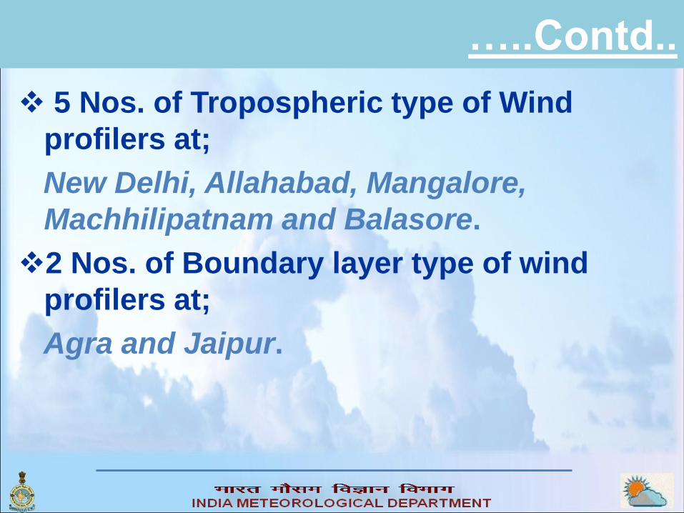
…..Contd..
5 Nos. of Tropospheric type of Wind
profilers at;
New Delhi, Allahabad, Mangalore,
Machhilipatnam and Balasore.
2 Nos. of Boundary layer type of wind
profilers at;
Agra and Jaipur.
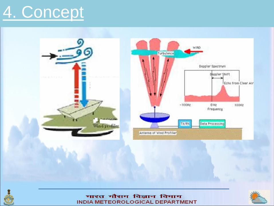
4. Concept

6.Products
•The hourly
averaged winds
displayed at each
height from every 6-
minute data
acquired.
• Wind speed
• Wind Direction

……Contd…..
• The vertical
velocity can be
calculated by the 6-
minute spectral
moments data
obtained from the
vertical beam.
•Wind Shear
• Turbulence

…..Contd..
•High signal power values
(greater than 60 dB) -High
moisture content or the
presence of precipitation
particles.
•Low power values (less than 40
dB) - Dry or stable atmosphere.
•Moisture advection and cloud
layers.
•Vertical extent of convection
•Bright bands (inferring the 0
degree C level) are all visible in
signal power displays

….Contd..
High time resolution data: typical 30 minutes.
Data almost instantaneous available
(Nowcasting)
Eulerian type of measurement (true vertical
profile, all Heights measured at same time).
Unambiguous profiles, independent of the
assimilation system.
Almost all weather.
Existing and proven.
…..Contd… The biggest advantage of the wind profiler is that it continuously
monitors the direction and speed of the wind without any break point or gap which makes it one of the accurate and efficient equipment in the field of environmental sciences and whether forecasting.
It can prevent many fatal disastrous affect that can occur in the situation of storm and ocean imbalance.
As it can measure the wind direction and speed above the sea level so it can easily detect from the speed of the wind about tidal waves and far storms that can hit the area in few hours.
Very useful in reporting and alarming the flight situations which can prevent the major crashes. The flight reporting center can inform the pilot on cockpit in time about the upcoming air pockets that can pressurize the aircraft.
This is done when the wind radar profilers measure the intensity turbulence and wind speed and inform the atmospheric stability to choose the appropriate action.
Hence an important tool for NOWCASTING.

SODAR system
SODAR (Sonic Detection And Ranging), is a
meteorological instrument which measures the
scattering of sound waves by atmospheric
turbulence. SODAR systems are used to
measure wind speed at various heights above
the ground of the lower layer of the atmosphere.
Sodar systems are like RADAR (radio detection
and ranging) systems except that sound waves
rather than radio waves are used for detection.
Other names used for sodar systems include
sounder, echosounder and acoustic radar.

Contd.
Obtaining atmospheric wind profiles at remote unmanned sites is a major technological challenge.
Wind profilers that are based on Doppler radar techniques do not have the resolution that is required for boundary layer studies.
Doppler sodar techniques offer the possibility of continuous wind profiling.
Doppler sodar systems work by transmitting acoustic pulses upward into the atmosphere and detecting the Doppler shift in the backscatter signal. By using off-vertical acoustic paths, it is possible to calculate the velocity profile of the reflector, which is then assumed to be identical to the wind profile (Neff and Coulter 1986).
Their disadvantage is that they are relatively power hungry compared to more passive systems, such as automatic weather stations.
Need….? (Winds in boundary layer)
PB (No. of ascents / Min ht measurable)
Wind profilers (Min ht measurable)
RS/RW (No. of ascents)
Lidar (High cost)

System Design
a. Doppler SODAR Antenna
b. Power System
c. Logging & Control unit
d. Calibration /
System Health

a. SODAR Antenna
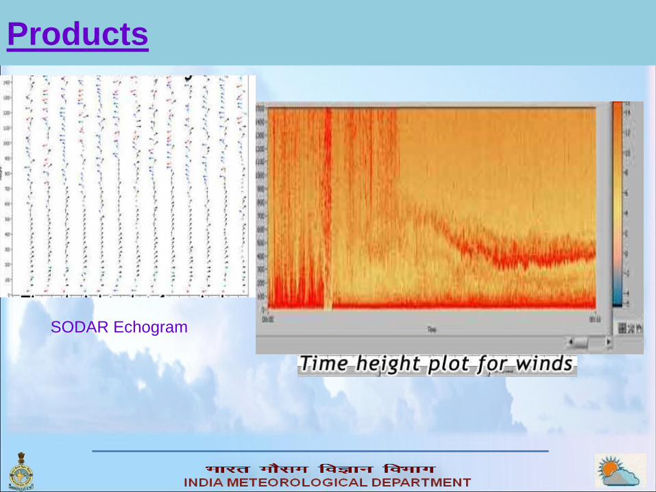
Products
SODAR Echogram

Applications
•Meteorology
•Aviation Meteorology
•Environmental Impact studies
•Planetary boundary layer research
•Inversion detection
•Sea / land breeze studies
•Research in atmospheric dynamics
•Environmental monitoring
•Wind energy site evaluation

Some SODAR installations in India
National Atmospheric Research Lab
(NARL) Gadanki, Tirupati
NPCIL, Kaiga, Uttar Karnataka
SPL, V.S.S.C Trivendrum
IITM, Pune
National Physical Laboratory (NPL), New
Delhi
Some Manufacturers
1. M/s SAMEER, Mumbai India
2. BIRAL (Bristol Industrial & Research
Associates Ltd), UK
3. Atmospheric Systems Corporation, CA, USA
4. Kipp & Zonen USA Inc.
5. SciTek Krungthep Co., Ltd, Huay-
Khwang,Bangkok
6. METEK GmbH, Germany
7. AQSystem Stockholm AB, Sweden

Pilot Sonde
Even after modernization of the PB network.The data availability has not increased much because the observations by optical theodolites have constraints of getting less data in disturbed weather like fog, rain, cloudiness etc when it is eagerly needed.
To overcome these weather constraints a weather proof system of PB observations is required.
In radiosonde / radiowind (RS/RW) observations, most of the Meteorological agencies in the world have adopted the GPS based system of observations.
On the same lines using the GPS technique the Pilot Balloon sonde may be developed and using that PB network may be further modernized.

Hardware Requirements
• The system requirement can be divided into two
parts;
A). The ground receiver system
B). The Pilotsonde
A).The GPS based ground receiver systems being
used with RS/RW system can be used for PB
observations, hence no separate ground
equipment are required.
• There are so many different type of brands are
available in the world market which can be
directly used.
• Even indigenous GPS based receiver system are
also available.

B). Pilot-sonde
The proposed pilot balloon sonde block diagram is given below;

Working
The schematic circuit diagram of Transmitter is given below;

Software requirements
The wind computation part of the RS/RW software may be used in the pilotsonde observations, as it is capable of;
1. Displaying real time wind data with graphical user interface,
2. Display of complete processed results along with plots,
3. Generation of flight report
4. Generation of coded PB messages.

Advantage
It is evident from GPs based RS/RW ascent that the flight termination in most of the cases is balloon burst.
The GPS receiver does not lose the signal while ascending.
The data availability depends mainly on the quality of balloon in all weather conditions.
Whereas, the presently used PB observations using optical theodolites are heavily dependent on weather conditions.
With optical theodolites, we get more data in clear weather and the data availability decreases with adverse weather.
We get less data or no data when it is urgently required by the forecaster.
The average height of PB balloon observations even after modernization of PB network, by providing each station a good quality optical theodolite system has an increase of just 0.5 to 1 km only and some stations have no change in their status of maximum height coverage.
It is mainly because of weather constraints.
The use of GPS based system in PB observations is expected to remove all these constraints.

Justifications
For the data availability
to a large extent, in
most of the cases up to
20 Kms of height,
especially in adverse
weather conditions,
when the data is
eagerly awaited, the
investment is justified.
Hence it is feasible to
implement the use of
pilotsonde on
operational basis in
upper air network of
IMD at PB stations.
5.4
1.2
6.6
2.7 4.2
6
2.1
5.1 5.7
1.1
18.9 21.4
20.1
19.6
20.5
21.1
20.6 18.7
19.2
20.9
1 2 3 4 5 6 7 8 9 10
Comparison of conventional vs GPS pilot observations
Conventiona Pilot balloon GPS pilot sonde
Ascent No.
Last
leve
l ach
ieve
d K
ms

Applications
•Meteorology
•Aviation Meteorology
•Environmental Impact studies
•Planetary boundary layer research
•Inversion detection
•Sea / land breeze studies
•Research in atmospheric dynamics
•Environmental monitoring
•Wind energy site evaluation
Future Plans
• Sustenance of 6 Nos of high quality GPS based system-
WMO-GUAN standard network.
• Expansion of GUAN standard network from 6 to 12 stations
by up-gradation of 6 operational RS/RW stations to GUAN
standard.
• Continuation of all 56 RS/RW stations with twice a day
ascents.
• Further expansion of operational RS/RW stations from 56 to
63 -procurement of GPS radiosondes from Indian sources to
promote ‘make in India’ initiative.
• Up-gradation of PB network to GPS based.