Embed Size (px)
DESCRIPTION
UPS system Manual Quasar 60-120 KVA
Citation preview
Deckblatt / Cover - I
ZUR BEACHTUNG:BEWAHREN SIE DIESE BETRIEBSANLEITUNG AN EINEN BEKANNTENUND FÜR DAS USV-PERSONAL LEICHT ZUGÄNGLICHEN ORT AUF.
NOTA:IT IS MANDATORY THIS TECHNICAL HANDBOOK IS HOUSED IN A PLACEKNOWN TO THE PERSONNEL OPERATING ON THE UPS, SO THAT THEYCAN FIND AND USE IT ANY MOMENT .
QUASAR60÷120 kVA
BetriebsanleitungTechnical handbook
Ausgabe 01- Issue 01 Januar 2003 - January 2003
ART DES DOKUMENTES - Document type: Allgemeine Beschreibung sowieInstruktionen für die Installation,Inbetriebnahme, Betrieb undWartung.
General overview, instructions forinstalling and starting up the Ups;User manual.
AUSGABE - Issue: 1
PRODUKT - Product: Statische unterbrechungsfreieStromversorgungsanlage in On-Line-Doppelumwandlungstechnikmit automatischem Bypass.
On-line type uninterruptible powersupply unit with double conversionand automatic by-pass.
MODELL - Model: USV / UPS 60 ÷ 120 kVA
HERSTELLJAHR - Manufacturing Date: 2002
KONFORMITÄT - conformity: CE-Kennzeichnung CE-Label
LEBENSERHALTENDE ANWENDUNGEN
Auf Grund der vielfältigen Anwendungsmöglichkeiten sowie der jeweils anzuwendenden Normen, empfiehlt der Hersteller einenVerkauf nur dann wenn der Käufer sich über den Verwendungszweck des Produktes völlig bewusst ist. Für Anwendungenwobei Funktionsstörungen oder Unzulänglichkeiten der USV zu lebensgefährdenden Situationen führen, trägt der Käufer diealleinige Verantwortung. Der Hersteller lehnt bei solchen Anwendungen jegliche Haftung oder Verantwortung für direkte oderindirekte Sach- oder Folgeschäden strikte ab.
LIFE-SUPPORTING APPLICATIONS
Die in dieser Anleitung enthaltenen Herstellerdaten können jederzeit ohne Vorankündigung geändert werden.Information in this handbook are given by the Manufacturer which reserves the right to modify them without any notice.
Due to the variety of applications and involved standards in each case , manufacturer does not recommend or knowinglysell it's product for any use not perfectly conscious.Applications where UPS malfunctions or inadequacy give rise to riskof human life shall be sole responsibility of the purchaser. Manufacturer accepts no liability for consequential harm insuch applications .

Inhaltsverzeichnis / Table of contents - I
INH
ALT
SV
ER
ZE
ICH
NIS
- C
ON
TE
NT
S
I
DT0344, Betriebsanleitung , Ausgabe 00 - Technical handbook, Issue 00UPS 60 -120 kVA
Rev Descrizione Data Controllato Realizzato Data
Approvato
Tipo di doc. Pagine n° Pag. totali
Cod.
U.T. 10/01/2003
EINLEITUNG ......................................... IIIA.1. Erste Hilfe ............................................ VA.2. Sicherheitsnormen...............................VIA.3. Sicherheitsmassnahmen ..................... IXA.4. Demontage und Entsorgung ................ XA.5. 10 oft gestellte Fragen (FAQ) ...............XI
1. - ALLGEMEINER ÜBERBLICK1.1. Allgemeine Beschreibung der USV .......21.2. Konfigurationen und Zusatz-
einrichtungen ........................................41.3. Funktionsprinzip ....................................7
2. - INSTALLATION2.1. Einleitung ..............................................32.2. Netzanschluss der USV ........................82.3. Anschluss an externe Vorrichtungen...142.4. Relais-Platine (optional) ......................172.5. Provisorischer Anschluss für die
Wiederaufladung der Batterie .............18
3. - INBETRIEBSETZUNG3.1. Erst-Einschaltung und Kontrollen .........33.2. Voreinstellungen ....................................73.3. Einrichten externer Vorrichtungen ....... 11
INHALTSVERZEICHNIS CONTENTS
FOREWORD .......................................... IIIA.1. First Aid ................................................ VA.2. Safety requirements ........................... VIA.3. Safety instructions .............................. IXA.4. Demolition and sell off .......................... XA.5. 10 Frequently asked questionsFAQ) .. XI
1. - GENERAL OVERVIEW1.1. UPS general description .......................21.2. Configuration and optional
equipment .............................................41.3. Operation ..............................................7
2. - INSTALLATION2.1. Introduction ...........................................32.2. UPS connection to mains .....................82.3. External devices connection ...............142.4. Relay card (optional) ...........................172.5. Temporary connection to enable
battery recharge..................................18
3. - SETUP3.1. Initial turn-on and checks ......................33.2. Setting options ......................................73.3. Pheripheral device set-up .....................9
DT0344-DE00

II - Inhaltsverzeichnis / Table of contents
INH
ALT
SV
ER
ZE
ICH
NIS
- C
ON
TE
NT
S
I
DT0344, Betriebsanleitung , Ausgabe 00 - Technical handbook, Issue 00UPS 60 -120 kVA
4. - BETRIEB UND WARTUNG4.1. Allgemeine Beschreibung .....................34.2. Das Frontpanel .....................................54.3. Rückseitiges Schaltfeld ......................144.4. Anweisungen für den Betrieb ..............154.5. Einsatz mit dem PC............................204.6. Fernanzeige (optional) ........................214.7. Ordentliche Wartung ...........................224.8. Periodische Wartung ..........................234.9. Zustände der USV (Normalbetrieb) .....254.10. Problemlösung ....................................27
4. - USER MANUAL4.1. General overview ..................................34.2. Front panel ............................................54.3. Rear distribution panel ........................144.4. User’s guide ........................................154.5. Use with the PC ..................................204.6. Remote panel (optional) ......................214.7. Routine maintenance ..........................224.8. Periodic maintenance .........................234.9. UPS status (normal mode) .................254.10. Troubleshooting...................................27

Einleitung / Foreword - III
EIN
LE
ITU
NG
- F
OR
EW
OR
D
A
DT0344, Betriebsanleitung , Ausgabe 00 - Technical handbook, Issue 00UPS 60 -120 kVA
Rev Descrizione Data Controllato Realizzato Data
Approvato
Tipo di doc. Pagine n° Pag. totali
Cod.
U.T. 10-01-2003
A.1. Erste Hilfe ..................................... VAusschalten im Notfall ......................... VErste Hilfe bei elektrischem Schlag ..... VKontakt mit korrosivenFlüssigkeiten ........................................ VEinnahme von ätzendenFlüssigkeiten ........................................ V
A.2. Sicherheitsnormen ......................VIBodenbelastung des Aufstellraumes ...VIZugänglichkeit der Räumlichkeiten.......VIAbmessungen der Räumlichkeiten ......VILüftung .................................................VIEinsatzbereich beachten .....................VIÜberhitzung ......................................... VIIVorsichtsmassnahmen Elektro ........... VIIAusschalten im Notfall ........................ VIIBatterien .............................................. VIISchutzhandschuhe ............................ VIIIIsolierender Bodenbelag..................... VIIIMetallgegenstände ablegen................ VIIINicht rauchen ..................................... VIIITechnischer Support .......................... VIIIInformation des Personals ................. VIII
A.3. Sicherheitsmassnahmen ............ IXVor der Installation ................................ IXDie Installation ...................................... IX
EINLEITUNG FOREWORD
DT0344-DE00
A.1. First aids ....................................... VEmergency Power Off ......................... VFirst aids for electric shock .................. VPeople contaminated by corrodingliquids ................................................... VPeople having ingested corrodingliquids ................................................... V
A.2. Safety rules.................................. VIMaximum load on the floor ................. VIRoom accessibility ............................. VIRoom dimensions ............................... VIVentilation ............................................ VIAllowed use ......................................... VIOverheating ....................................... VIIElectrical caution ................................ VIIEmergency Power Off ....................... VIIBatteries ............................................. VIIProtective gloves .............................. VIIIIsolating carpet .................................. VIIIStrip metal objects ............................ VIIIDo not smoke ................................... VIIITechnical support .............................. VIIIPersonnel info ................................... VIII
A.3. Safety instruction ........................ IXBefore starting installation ................... IXInstallation ........................................... IX
IV - Einleitung / Foreword
EIN
LE
ITU
NG
- F
OR
EW
OR
D
A
DT0344, Betriebsanleitung , Ausgabe 00 - Technical handbook, Issue 00UPS 60 -120 kVA
Schutzerdung....................................... IXFehlerstromschutzschaltung ............... IXBei Brandausbruch .............................. IXSchulung des Personals ...................... IX
A.4. Demontage und Entsorgung ...... XEntsorgung der Verpackung ................. XEntsorgung der Metallteile .................... XEntsorgung der Elektronikplatinen........ XEntsorgung der Batterien ..................... XEntsorgung weiterer Komponenten ..... X
A.5. 10 oft gestellte Fragen (FAQ) .......XI
Earth connection ................................. IXEarth leakage protection ..................... IXIn case of fire ...................................... IXPersonnel training ............................... IX
A.4. Dismantling and disposal ............ XDisposal of packing ............................. XDisposal of metal parts ........................ XDisposal of electronic cards ................ XDisposal of batteries ............................ XDisposal of other parts ......................... X
A.5. F.A.Q. ............................................ XI

Einleitung / Foreword - V
EIN
LE
ITU
NG
- F
OR
EW
OR
D
A
DT0344, Betriebsanleitung , Ausgabe 00 - Technical handbook, Issue 00UPS 60 -120 kVA
A.1. ERSTE HILFE
Ausschalten im NotfallIm Notfall kann die Lastversorgung, durchBetätigen der Taste NOT-AUS oderAusschalten aller rückseitigen USV-Schalter, abgeschaltet werden.
Erste Hilfe bei elektrischem SchlagSchalten Sie die Versorgungsspannungab oder verwenden Sie als Selbstschutztrockenes Isoliermaterial um das Opfervon den Spannungsführenden Teilen zuentfernen.BERÜHREN SIE DAS OPFER NICHT MITBLOSSEN HÄNDEN SOLANGE DIESERNOCH SPANNUNGS-FÜHRENDE TEILEBERÜHRT. SOFORT QUALIFIZIERTEHILFE ANFORDERN.
Kontakt mit korrosivenFlüssigkeitenBei Hautkontakt mit Batterie-Elektrolyt, diebetroffene Stellen reichlich mit fliessendemWasser spülen; verseuchteKleidungsstücke entfernen; betroffeneStellen mit Mullbinden schützen.
Bei Augenkontakt sofort mit einerSalzlösung oder fliessendem Wasserwährend mindestens 10 Minutenausspülen.
Einnahme von korrosivenFlüssigkeitenWenn der Elektrolyt geschluckt wurde,verursachen Sie kein Brechen aber lassenSie das Opfer so viel Wasser oder Milchwie nur möglich trinken.
IN ALLEN FÄLLENSOFORTIGE MEDISCHE HILFE
ANFORDERN
A.1. FIRST AIDS
Emergency Power OffIn an emergency case, the load supplycan be disconnected opening all the leverswitches fitted in the front lower side of theUPS, opening the door.
First aids for electric shockTurn off or open the power supply line, oruse an isolated dry material to protect itselfwhile moving the victim far away from anyelectrical cable.DO NOT TOUCH THE VICTIM WITHHANDS UNTIL THE LATTER IS FARAWAY FROM ANY ELECTRIC WIRE.SEEK IMMEDIATELY FOR MEDICALHELP.
People contaminated by corrodingliquidsShould the batteries electrolyte come intocontact with skin, rinse abundantly withwater the skin; remove the contaminatedclothes; apply dry gauze to the contami-nated skin.Should the batteries electrolyte come intocontact with eyes, wash them immediatelywith a saline water solution or with freshwater for 10 minutes at least.
People having ingested corroding liq-uidsShould the batteries electrolyte ingested,do not induce vomiting but let the victimdrink as much water or milk as he likes.
AT ALL EVENTS SEEKIMMEDIATELY
FOR MEDICAL HELP

VI - Einleitung / Foreword
EIN
LE
ITU
NG
- F
OR
EW
OR
D
A
DT0344, Betriebsanleitung , Ausgabe 00 - Technical handbook, Issue 00UPS 60 -120 kVA
A.2. SICHERHEITSNORMEN
Bodenbelastung desAufstellraumesIn Anbetracht des USV-Gewichtes (Kap.1.5 - Techn. Daten), muss der Boden desAufstellungsraumes entsprechendeTrgfähigkeit aufweisen. Im Zweifelsfalleinformieren Sie sich beim Unternehmer.
Zugänglichkeit der RäumlichkeitenDer Raum muss genügend Freiraum fürdie Installation aufweisen: dieTürabmessungen müssen einenDurchlass der Anlage gestatten. Für denAnlagentransport verwenden Sie einPalettrolli mit entsprechenderHebeleistung.
Abmessungen der RäumlichkeitenFür normale Wartungsarbeiten muss umder Anlage genügend Freiraum zurVerfügung stehen. Zwischen derOberkante der USV und der Decke desAufstellungsraumes muss mindestens 400mm freie Höhe vorhanden sein.
LüftungDie Betriebstemperatur der USV beträgtzwischen 0 °C und 40 °C. Die idealeRaumtemperatur sollte 25 °C nichtübersteigen. Die Verlustwärme der USVwird durch interne Ventilatorenausgestossen und an der Umgebungabgegeben; diese muss durch einentsprechendes Kühl- (Zwangskühlung)oder Klimasystem aus dem USV-Raumabgeführt werden.
Einsatzbereich beachtenDie Anlage muss zweckentsprechendeingesetzt werden. Beachten Sie dieAngaben in Kap. 4 - Betrieb und Wartung.
A.2. SAFETY RULES
Maximum load on the floor
According to the weight of the UPS System(see chapt. 1.5 - Characteristics), theinstallation site must have a floor capable tocarry the equipment weight. When in doubt,consult the building firm.
Room accessibilityThe room must be suitable to permit allinstallation manoeuvres: consider the doordimension in order to facilitate the passageof the equipment. For equipment moving atranspallet capable to lift the UPS weight isrequired.
Room dimensions and pollutionAll around the UPS a minimum free space,enough to guarantee the correct executionof maintenance jobs must be kept. Be-tween the top of the UPS and the installa-tion site ceiling the minimum distance mustbe at least 400 mm.Room has to be cleanand without conductive dusts.(max pollutiondegree 2)
VentilationThe UPS working temperature is in therange 0 °C to 40 °C. The ideal environmen-tal temperature should not exceed 25 °C.The UPS' heat is extracted by internal fansand dissipated in the air; the heat can beremoved from the room in which the UPS isinstalled by means of a fan system (forcedventilation) or by an air conditioning sys-tem.
Allowed useThe unit must be used as intended. Followthe instructions given in Chapt. 4 - User'sManual.

Einleitung / Foreword - VII
EIN
LE
ITU
NG
- F
OR
EW
OR
D
A
DT0344, Betriebsanleitung , Ausgabe 00 - Technical handbook, Issue 00UPS 60 -120 kVA
ÜberhitzungUm Überhitzung vorzubeugen dürfen diean der Anlage vorgesehenenLüftungsschlitze nicht abgedeckt werden.
Vorsichtsmassnahmen ElektroIm Inneren der Anlage sind gefährlicheSpannungen vorhanden.Öffnen Sie die Anlage und ZusatzschränkeNICHT: es befinden sich keine reparierbareBauteile in der Anlage.Es dürfen keine intene Schutz-abdeckungen entfernt werden.
Alle durch die USV versorgtenHauptschaltern müssen wie folgtgekennzeichnet sein: “Vor Arbeiten andiesem Schalkreis USV freischalten”.
Ausschalten im NotfallDie Anlage ist mit E.P.O. ausgerüstet(Emergency Power Off - Not Aus). DieseFunktion wird durch betätigen derangeschlossenen externen Not-Aus-Tasteaktiviert. Die Funktion verursacht eineTrennung der USV von der Last und derBatterie. Wenn der Zuleitungsschalter nichtmit einem Entladungsschaltkreisausgerüstet ist, werden im Inneren nochgefährliche Spannungen vorhanden sein.
BatterienBei der Elektrolyse kommt Wasserstofffrei. Wenn die Wasserstoffkonzentrationim Batterieraum einen gewissen Wertübersteigt, besteht Explosionsgefahr. ZurVorbeugung muss, entsprechend der NormEN50091-1, eine dem-entsprechendeLüftung des Batterieraumes vorgesehenwerden.Wenn die mittlere Raumtemperatur 25°Cübersteigt, verringert sich die Batterie-lebensdauer und beträgt im Allgemeinen50% pro 10°C Zunahme. Die idealeRaumtemperatur beträgt 15°C bis 25°C.
OverheatingTo prevent overheating do not obstruct theventilation openings for flow of air of the unit.DON'T leave objects on the top of the unit.
Electrical cautionDangerous voltage is present inside the unit.The User must not open the Ups cabinet orauxiliary cabinets: the components inside theunit are not repairable by the User.Moreover, do not remove any protective cov-ers from inside the Ups cabinet.
All primary power switches installed upstreamof the Ups must be labelled as follows: “Iso-late UPS Uninterruptible Power Supply) be-fore working on this circuit”.
Emergency Power OffThe unit is provided with the E.P.O. (Emer-gency Power Off). This function is activatedby pressing the external emergency button towhich the Ups has been connected. Thisfunction provides Ups disconnection fromthe load and from the battery.Dangerous voltage will still be present insidethe unit, (charged capacitors) wait for 5 min-utes before working on the unit.
BatteriesDuring electrolysis, batteries release hydro-gen gas. There is a risk of an explosion if theamount of hydrogen in the battery room be-comes too high. Ensure appropriate ventila-tion of the battery room according to theStandard EN50091 -1, to prevent the risk ofan explosion.If the average temperature in the room ex-ceeds 25 °C the battery lifetime is greatlyreduced. The lifetime is reduced of 1/2 for 10°C temperature raising. The ideal tempera-ture should range from 15 to 25 °C.
VIII - Einleitung / Foreword
EIN
LE
ITU
NG
- F
OR
EW
OR
D
A
DT0344, Betriebsanleitung , Ausgabe 00 - Technical handbook, Issue 00UPS 60 -120 kVA
Intakte Batterien sind trocken und sauber,es tropft keine korrosive Flüssigkeit ausdem Behälter. Nach einem zufälligenSchlag gegen dem Gehäuse, prüfen siediesen sorgfältig!Ein beschädigter Behälter lässt Elektrolytaustreten, der auf der Haut Verbrennungenverursacht und Metalle, Farbanstriche undTextilien korrodiert und Kurzschlüsseverursacht.
SchutzhandschuheVerwenden Sie Gummihandschuhe beiArbeiten an beschädigten Batterien.
Isolierender BodenbelagBei Arbeiten an der USV verwenden SieGummimatte und isoliertes Werkzeug.
Metallgegenstände ablegenBei Arbeiten an der USV entfernen Siemetallene Gegenstände wie: Ringe, Uhr,Schreiber, usw. die einen Kurzschlussverursachen können. Batterien sind immeraktiv; ein Kurzschluss kann Metalleschmelzen und grosser Schadenanrichten.
Nicht rauchenBei Arbeit an der USV RAUCHEN Sie NICHToder hantieren keine offene Flamme undziehen keine Funken. Tragen Sie keineKleidung die sich statisch auflädt.
Technischer SupportDie Wartung dieser Anlage darf nur durchqualifiziertem Fachpersonal erfolgen.
Information des PersonalsDas gesamte Personal dass die USVbedient, muss mit vorliegende Normenund Weisungen vertraut sein.
The installed battery, when in good condition,looks dry and no corrosive liquid drops out itscase.In case of accidental crash inspect accuratelythe batteries !A broken case can the electrolyte drops out; thelatter can cause burns of the skin, corrodemetal cabinet, finishing coating and fabrics orcause short-circuiting among the internal partsand the electrolyte.
Protective glovesWhen handling damages batteries it is manda-tory to wear protective gloves.
Isolating carpetWhile working on the UPS, stand on a rubbercarpet and use isolated tools only.
Strip metal objectsWhile working on the UPS, strip all personalobjects: ring, watch, steel pen, etc. which cancause short-circuiting when working on batter-ies. The batteries are always on and, if shortcircuited they can fuse metals and cause manydamages.
Do not smokeWhile working on the UPS, DO NOT SMOKE,do not use flames, avoid to create electric arcswhen working on the UPS; do not wear clothesthat can create static charges.
Technical supportThis equipment must be serviced by qualifiedpersonnel.
Personnel InfoAll the personnel operating on the UPS, special-ized or not, have to be acquainted with all theseSafety Instruction.

Einleitung / Foreword - IX
EIN
LE
ITU
NG
- F
OR
EW
OR
D
A
DT0344, Betriebsanleitung , Ausgabe 00 - Technical handbook, Issue 00UPS 60 -120 kVA
A.3. SICHERHEITSVORSCHRIFTEN
Vor der InstallationÖffnen Sie die Schalter ON/OFF, INPUT,MANUAL BY-PASS und OUTPUT (alleHebel sind horizontal) um die Anlagevollständig freizuschalten; die Zuleitungsowie die externe Batterie müssen von derUSV getrennt sein. Entfernen Sie dieSicherungen im Batterieschrank und/oderöffnen Sie den Batterieschalter.
Die InstallationDie Installation dieser Anlage muss durchqualifiziertem Fachpersonal erfolgen,entsprechend Kap. 2 - Installation.
SchutzerdungVor Anschluss der Zuleitungskabel musszuerst die Schutzerde angeschlossenwerden.
FehlerstromschutzschaltungDieses Gerät weist einen hohen Leckstromzu der Schutzerdung auf. Der maximaleLeckstrom beträgt 300mA.Bei der Einstellung der vorgeschaltetenFehlerstromschutzschaltung muss dieserzusätzlicher Anteil, zusammen mit demLastanteil, berücksichtigt werden (wirempfehlen die Installation eines Gerätesfür bis zu 500mA Leckstrom).
Bei BrandausbruchIm Inneren der USV sind, auch beigeöffneten Schaltern, gefährlicheSpannungen vorhanden!Verwenden Sie folgedessen beiBrandausbruch KEIN WASSER um dasFeuer zu löschen.
Schulung des PersonalsDas gesamte Personal muss daraufgeschult sein, die Not-Abschaltungauszuführen (siehe A.1. - Erste Hilfe).
A.3. SAFETY INSTRUCTION
Before starting installationTo completely isolate the equipment, theswitches ON/OFF, INPUT, MANUAL BY-PASSe OUTPUT must be switched off (all the lever-switches orizontal) the input supply and externalbattery supply should be isolated from the UPS.Remove all the fuses in the Auxiliary Batterycabinet and/or open battery isolator.
InstallationThis equipment must be installed by qualifiedpersonnel, following instruction given in chapter2 - Installation.
High leakage currentConnect protective earth before power supplycables.
Earth leakage protectionThis device has a high leakage current towardsprotective earthing. The maximum earth leak-age current is 300 mA. When setting the thresh-old of the earth leakage circuit breaker installedupstream from this equipment consider thisamount of current and the current amount due tothe loads.It is suggested to install a protectiondevice of at least 500mA.
In case of fireInside the Uninterruptible Power Supply unitdangerous voltage is present, even if all theswitches are off !For this reason in case of a fire: do not usewater to put out a fire.
Personnel trainingAll personnel operating on the UPS have to betrained to perform the Emergency Power Off(see A.1. - First Aids).

X - Einleitung / Foreword
EIN
LE
ITU
NG
- F
OR
EW
OR
D
A
DT0344, Betriebsanleitung , Ausgabe 00 - Technical handbook, Issue 00UPS 60 -120 kVA
A.4. DEMONTAGE UND ENTSORGUNG
IBei Abbruch der USV müssen derenKomponenten Spezialfirmen für Entsorgung undWiederverwertung von Industrieabfällenübergeben werden:
Entsorgung der VerpackungDie Verpackung besteht aus biologischabbaubarem Karton und kann ohne Weiteresder Zelluloseverwertung übergeben werden.
Die Formteile aus polyethylen-Schaumstoff sindchemisch inaktiv und können auf der Müllhaldeentsorgt werden, wo sie weder Gas entwickelnnoch das Grundwasser verunreinigen.
Entsorgung der MetallteileDie Gehäuse-Metallteile, sowohl die gespritztenwie die blanken Teile, können normalwiederverwertet und dem Altmetallhändlerübergeben werden.
Entsorgung der ElektronikplatinenDie Elektronikplatinen müssen zwangsmässigFirmen für die Entsorgung von Elektronikbauteilenübergeben werden.
Entsorgung der BatterienBatterien müssen von allen anderen Teilen derUSV getrennt und entsprechend der Vorschriftenfür giftige und gefährliche Stoffe entsorgt werden.
Entsorgung weiterer KomponentenWeitere Teile der USV, wie Gummidichtungen,Kunststoffteile und Kabel werden Spezialfirmenfür die Entsorgung von Industrieabfällenübergeben.
A.4. DISMANTLING AND DISPOSAL
Should the UPS be dismantled, the parts makingit up must be assigned to Companies special-ised in the disposal and recycling or industrialwaste, specifically:
Disposal of packingPacking consists of biodegradable material. Thecardboard can be sent to Companies assignedto recuperating cellulose.
Polyurethane foam protective profiles are chemi-cally inert, they do not contribute to gas formingnor to pollute water; their disposal can be as-signed to Companies specialised in the disposalof industrial materials.
Disposal of metal partsThe metal parts of the cabinet, both the var-nished ones and the stainless steel ones, areregularly recovered by companies specialisedin the scrapping of metals.
Disposal of electronic cardsIt is mandatory that the electronic cards bedisposed of companies specialised in the dis-posal of electronic components.
Disposal of batteriesBatteries must be separated from any other partof the UPS and disposed according to the normslocally current about disposal of toxic and nox-ious industrial materials.
Disposal of other partsThe disposal of other parts making up the UPS,i.e., rubber gaskets, plastic materials and wiringis assigned to Companies specialised in thedisposal of industrial materials.

Einleitung / Foreword - XI
EIN
LE
ITU
NG
- F
OR
EW
OR
D
A
DT0344, Betriebsanleitung , Ausgabe 00 - Technical handbook, Issue 00UPS 60 -120 kVA
A.5. 10 OFT GESTELLTE FRAGEN (FAQ)
Wie muss die USV installiert werden?Für die USV sehen Sie nach unter:
- Kap. 2 - Installation.
Für die Installation des Zusatzbatterieschrankessehen Sie nach unter:- Beilage 1 : Zusatzbatterieschrank.
Für die Installation des Transformerschrankessehen Sie nach unter:- Beilage 2 : Transformerschrank.Notwendiges Personal: ElektrikerWie muss die USV inbetriebgesetzt werden?Für die Erst-Inbetriebsetzung sehen Sie nachunter:- Kap. 3 - Inbetriebsetzung.Notwendiges Personal: Prüftechniker
Für jedes Mal danach, sehen Sie unter:- Kap. 4 - Betrieb und Wartung, § 4.4.Notwendiges Personal: unbestimmtMuss die USV gewartet werden?Der Wartungsaufwand ist sehr gering, sehenSie nach unter:- Kap. 4.7: Ordentliche Wartung
Notwendiges Personal: unbestimmtDie Batterie ist entladen, wie gehe ich vor?Sehen Sie nach unter:- Kap. 2.5.1: Batteriewiederaufladung
Notwendiges Personal: unbestimmtch möchte das gesamte Betriebspersonalfür einfache USV-Befehle schulen; was tueich?Einen Schnellkurs über die Themen folgenderKapitel halten:- Einleitung- Kap. 4 - Betrieb und WartungNotwendiges Personal: für Alle
A.5. F.A.Q.
How have you to install your UPS?Refer to the instructions supplied in the followingdocuments:- Chapt. 2 - Installation.
To install the Battery Cabinet see the document:- Annex 1 : Battery cubicle
To install the Transformer Cabinet see thedocument:- Annex 2 : Transformer CabinetPersonnel required: fitters/electricians
Where to find instructions to place UPS intooperations?The first time, refer to the instructions supplied inthe following documents:- Chapt. 3 - Setup.Personnel required: Final test techniciansThe following times, refer to the following:- Chapt. 4 - User manual, § 4.4.Personnel required: anyone can do that.
How to make the UPS maintenance ?Refer to the instructions supplied in the followingdocuments:- Chapt. 4.7: Routine Maintenance
Personnel required: anyone can do that.
The battery is low, what to do ?Refer to the following documents:- Chapt. 2.5.1: Battery recharging
Personnel required: anyone can do that.
The personnel should be upgraded on thesimplest UPS's commands, how to do?Have a short training about these two followings:
- FOREWORD- Chapt. 4 - User manual
Personnel required: anyone can do that.

XII - Einleitung / Foreword
EIN
LE
ITU
NG
- F
OR
EW
OR
D
A
DT0344, Betriebsanleitung , Ausgabe 00 - Technical handbook, Issue 00UPS 60 -120 kVA
Die USV ist ausgefallen, was tun?Sehen Sie nach unter:- Kap. 4.4.3: Einschalten vom Manuellen
Bypass und Ausschalten des Planet ohneUnterbrechung der Lastversorgung.
- Kap. 4.8: Fehlersuche.
Notwendiges Personal: allgemeine Techniker.Wie verwende ich den PC mit der USV?Sehen Sie nach im Handbuch zum ProgrammUPS MANAGEMENT SOFTWARE.
Notwendiges Personal: Personal mit IT-Erfahrung (Einrichten von PC).Was bedeuten die Anzeigen derFernmeldung?Sehen Sie nach unter:- Kap. 4 - Betrieb und Wartung, § 4.6.Notwendiges Personal: unbestimmtWas tue ich bei einer Alarmmeldung?Sehen Sie nach unter:- Kap. 4.8 - Fehlersuche
Notwendiges Personal: unbestimmtWie bekomme ich technisch-kommerzielleInformation über die USV?Sehen Sie nach unter:- Kap. 1 - Allgemeine Informationen und
technische Daten.
The UPS is failed, what to do ?Refer to the following documents:- Chapt. 4.4.3: Manual by-pass connection
and UPS switching OFF without cutting offpower to the load.
- Chapt. 4.8: Troubleshooting.
Personnel required: support technician.
How to use the PC connected to the UPS ?Refer to the instructions supplied with the UPSMANAGEMENT SOFTWARE.
Personnel required: experienced with PersonalComputers and relevant applications.
What do the Remote panel lamps mean ?Refer to the following documents:- Chapt. 4 - User manual, § 4.6
Personnel required: anyone can do that.
How to proceed when the UPS is alarmed ?Refer to the following documents:- Chapt. 4.8 - Troubleshooting
Personnel required: support technician.
How to gain informations of the technical-commercial type about the UPSRefer to the following documents:- Chapt. 1 - General Overview

Allgemeiner Überblick / General overview -1- 1
AL
LG
EM
EIN
ER
Ü
BE
RB
LIC
K -
GE
NE
RA
L O
VE
RV
IEW
1
DT0344, Betriebsanleitung , Ausgabe 00 - Technical handbook, Issue 00UPS 60 -120 kVA
1 - ALLGEMEINER ÜBERBLICK 1 - GENERAL OVERVIEW
Inhalt
1.1. Allg. Beschreibung der USV ........ 21.1.1.Einsatzbereiche ................................... 21.1.2.Leistung und Autonomie ..................... 21.1.3.Sicherheit und einfacher Betrieb ......... 31.1.4.Einzelheiten des Aufbaues ................. 3
1.2. Konfigurationen und Zusatz-einrichtungen ................................ 4
1.2.1. Basis-Konfiguration ............................ 41.2.2.Zusatzbatterieschrank ......................... 51.2.3.Transformerschrank ............................ 51.2.4.Zubehör ............................................... 6
1.3. Funktionsprinzip ........................... 71.3.1.Eingangsstufe, Leistungsstufe und
Ausgangsstufe..................................... 71.3.2.Prinzipschema der USV
(Doppel-Umwandlung mit Bypass) ...... 81.3.3.Logik und Hilfskreise ........................... 91.3.4.Batterien ............................................ 101.3.5.Relais-Platine .................................... 101.3.6.Manueller Bypass .............................. 101.3.7.Frontpanel ......................................... 10
Table of contents
1.1. UPS general description .............. 21.1.1.UPS type of application ....................... 21.1.2 Power and autonomy .......................... 21.1.3.Safety and ease of use ....................... 31.1.4.Construction details ............................. 3
1.2. Configuration and optionalequipment ..................................... 4
1.2.1.Base configuration.............................. 41.2.2.Batteries cabinet .................................. 51.2.3.Transformer cabinet ............................. 51.2.4.Accessories ......................................... 6
1.3. Operation ....................................... 71.3.1.Input Stage, Power Module and Output
Stage ................................................... 71.3.2. UPS functional drawing (double con-
version/by-pass) .................................. 81.3.3.Logic and Auxiliary circuits .................. 91.3.4.Batteries ............................................ 101.3.5. Relay card......................................... 101.3.6.Manual by-pass ................................. 101.3.7.Front panel ........................................ 10
Rev Descrizione Data Controllato Realizzato Data
Approvato
Tipo di doc. Pagine n° Pag. totali
Cod.
U.T. PTX 20-04-2002
DT0344-DE00
1 - 2 - Allgemeiner Überblick / General overview
AL
LG
EM
EIN
ER
Ü
BE
RB
LIC
K -
GE
NE
RA
L O
VE
RV
IEW
1
DT0344, Betriebsanleitung , Ausgabe 00 - Technical handbook, Issue 00UPS 60 -120 kVA
1.1. ALLG. BESCHREIBUNG DERUSV
Die geringen Gehäuseabmessungenverstecken die beachtenswerten Leistungendes Gerätes: die Anlage ist in moderner Formaufgebaut und besteht aus einer tragendenStruktur aus verzinktem Blech auf Laufrollen fürbequemes umplatzieren; die äussereVerkleidung besteht aus sauber gespritztemBlech.
1.1.1. Einsatzbereiche der USVDie neue USV-Reihe wurde zur Versorgungempfindlicher elektronischer Apparaturen(speziell Datenverarbeitungs-anlagen) mit einergeregelten sauberen Versorgungsspannungohne Spannungs- und Frequenzschwankungenentwickelt. Sie wird somit hauptsächlich inSpitäler, Polizeiposten, Strassentunnels,Sendeanlagen, Banken, Forschungsanstalten,Ingenieur- und Verwaltungsunternehmen sowievielen weiteren Anwendungsgebieteneingesetzt.
1.1.2. Leistung und AutonomieDank dem modularen Aufbau ist die USV-Reihein Modelle mit Nennleistungen von 60 bis120kVA, alle bei cosϕ = 0,8, erhältlich.Alle Modelle haben keine interne Batterie; fürjede Batterie-Autonomie muss ein externerBatterieschrank vorgesehen werden.
1.1.3. Sicherheit und einfacher BetriebAlle Befehlsgeräte sind vollständig von hohenBetriebsspannungen entkoppelt und isoliert; derIsolation und galvanischen Trennung allerKomponenten ausserhalb vom Gehäuse wurdespezielle Beachtung geschenkt.
1.1. UPS GENERALDESCRIPTION
The small outer size of the cabinet hides theextraordinary power of UPS. The equipmenthas a modern structure. It consists of a galva-nized steel iron supporting structure mountedon wheels so as to easily move it around in theroom. The supporting structure is covered witha varnished steel shell.
1.1.1. UPS type of applicationThe latest UPS is an uninterruptible assemblydesigned to deliver stabilized and filtered powerto sophisticated electronic equipment (dataprocessing systems). Since the latter are nor-mally utilized in medical centers, police stations,motorway tunnels, broadcasting stations, banks,technical and administrative offices and otherapplications they must guarantee a power sourcefree from voltage and frequency variations.
1.1.2 Power and autonomyThe modular design of UPS allows to supply itin versions featuring a nominal power from60kVA to 120kVA, all with cos ϕ = 0,8.All versionas have not battery inside, an exter-nal battery cubicle has to be provided for eachautonomy.
1.1.3. Safety and ease of useAll the controls available are perfectly isolatedand decoupled from the high working voltages,likewise for the outer parts of the containerwhich have been carefully isolated and galvani-cally separated .

Allgemeiner Überblick / General overview -1- 3
AL
LG
EM
EIN
ER
Ü
BE
RB
LIC
K -
GE
NE
RA
L O
VE
RV
IEW
1
DT0344, Betriebsanleitung , Ausgabe 00 - Technical handbook, Issue 00UPS 60 -120 kVA
Die Überwachungskreise für Überlast undÜbertemperatur gewähren sofortige undangemessene Reaktion sollten diese währenddem Betrieb ansprechen.Eine oder mehrere Not-Tasten (nicht imLieferumfang enthalten),können angeschlossen werden und erlaubendie vollständige Abschaltung der USV.Da die USV voll-automatisch funktioniert,müssen keine Betriebsbefehle erteilt werden.Das Frontpanel ist demnach sehr einfachaufgebaut und dient nur der regelmässigenPrüfung des korrekten Betriebes.Die USV kann auf einfachster Weise mittels PCmit entsprechendem Kommunikations-programm (optional) fernüberwacht werden.
Ein Fernmeldepanel (optional) kann ebenfallsan der USV angeschlossen werden; dieseserweist sich als sehr nützlich wenn die USV sichin einem unbewachten Raum befindet: esermöglicht die Betriebsüberwachung, wiederholtdie Alarmmeldungen durch LED-Anzeigen undaktiviert einen Summer.
1.1.4. Konstruktive EinzelheitenDas Frontpanel beinhaltet die Bedienelemente.Hinter der Türe, im unteren Teil der USV,befinden sich die Anschlussklemmen derSchalter die gleichzeitig dieLeistungsanschlüsse für Ein- und Ausgang derAnlage darstellen.Die Kabelzuleitung kann nach Wunsch sowohlvon unten wie von oben erfolgen.
Checks have been made both on overload andon overtemperature to guarantee a prompt andfitting intervention should one of the aforemen-tioned conditions arise during operation.One or more emergency push-buttons (not sup-plied) can be connected. These, in case of fire,fully de-activate the UPS.
Since UPS operates in an automatic mode,there is no need to forward commands.Therefore, the front panel is extremely easy andoperation is the sole function to have a periodi-cal check.UPS is easily managed through a personalcomputer and through an interacting program(optional).
A remote panel (optional) can be connected toUPS for remote control operations.The remotepanel is considered essential when the UPS isinstalled in unmanned rooms: it displays theoperating mode, repeats the alarms through thelighting up of LEDs and activates a buzzer.
1.1.4. Construction detailsThe control panel is placed on the front door.Behind the door, in the lower part of the cubille,I/0 power switches terminals are also I/0 con-nectors for over power cables.Power cables inlet i s provided from the top orfrom the bottom of the cubicle.

1 - 4 - Allgemeiner Überblick / General overview
AL
LG
EM
EIN
ER
Ü
BE
RB
LIC
K -
GE
NE
RA
L O
VE
RV
IEW
1
DT0344, Betriebsanleitung , Ausgabe 00 - Technical handbook, Issue 00UPS 60 -120 kVA
1.2. KONFIGURATIONEN UNDZUSATZ-EINRICHTUNGEN
1.2.1. Basis-Konfiguration
Die Basis-Konfiguration besteht aus dertransformerlosen USV im eigenen Gehäuse.Batterien sind nicht enthalten.
1.2. CONFIGURATION ANDOPTIONAL EQUIPMENT
1.2.1. Base configuration
The base configuration provides trafolessUPS equipped in its cubicle.Batteries aren't provided.
Basis-KonfigurationBase configuration

Allgemeiner Überblick / General overview -1- 5
AL
LG
EM
EIN
ER
Ü
BE
RB
LIC
K -
GE
NE
RA
L O
VE
RV
IEW
1
DT0344, Betriebsanleitung , Ausgabe 00 - Technical handbook, Issue 00UPS 60 -120 kVA
1.2.2. BatterieschrankAuf Anfrage kann die USV mit Batterien für
die gewünschte Autonomie geliefert werden.Die Batterien können in einem Gehäuse mitgeeigneten Abmessungen, komplett mitentsprechenden Trennelementen,untergebracht werden. Falls die Batteriie nichtin unmittelbarer Nähe der USV aufgestellt wird,muss ein geeignetes Trennelement in einemWandgehäuse bei der USV vorgesehen werden.
1.2.3. TransformerschrankEin Zusatzschrank mit Trenntransformer
für bestimmte Einsatzgebiete, wie z.B.Spitalanwendungen, ist erhältlich.Der Standardtransformer ist Tri-phase/Tri-phasemit einem Übersetzungsverhältnis von 1:1; aufAnfrage ist auch ein anderes Verhältnis möglich.Im gleichen Gehäuse kann ein Transformatorzur Reduzierung der netzseitigenStromoberwellen untertgebracht werden.
BatterieschrankBatteries cabinet .
USVUPS
1.2.2. Batteries cabinetUPS can be supplied with a suitable battery
cabinet for the required autonomy . Cabinetcontains also dc isolator to disconnect batterywhen necessary.If battery location is not nearthe UPS , a wall cabinet containing batteryisolator must be provided near UPS.
1.2.3. Transformer cabinetAn optional cabinet with a galvanic isolating
transfomer is available and this is specificallyutilized in medical centers.The standard transformer features a three-phase/three-phase with 1:1 ratio characteristic,(the transformer ratio can be customized).In the same cabinet could be equipped a suit-able transformer for line current armonic.
1 - 6 - Allgemeiner Überblick / General overview
AL
LG
EM
EIN
ER
Ü
BE
RB
LIC
K -
GE
NE
RA
L O
VE
RV
IEW
1
DT0344, Betriebsanleitung , Ausgabe 00 - Technical handbook, Issue 00UPS 60 -120 kVA
1.2.5. Zubehör - Accessories
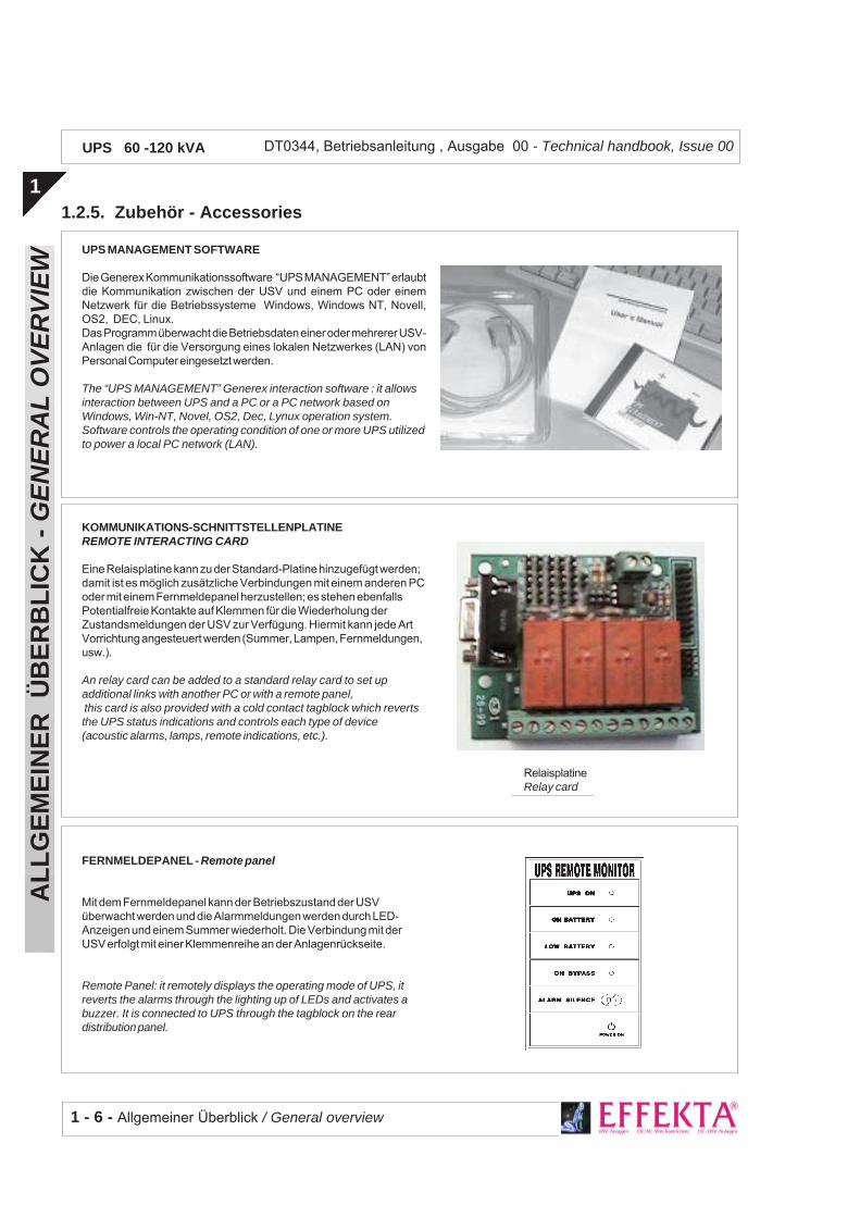
UPS MANAGEMENT SOFTWARE
Die Generex Kommunikationssoftware “UPS MANAGEMENT” erlaubtdie Kommunikation zwischen der USV und einem PC oder einemNetzwerk für die Betriebssysteme Windows, Windows NT, Novell,OS2, DEC, Linux.Das Programm überwacht die Betriebsdaten einer oder mehrerer USV-Anlagen die für die Versorgung eines lokalen Netzwerkes (LAN) vonPersonal Computer eingesetzt werden.
The “UPS MANAGEMENT” Generex interaction software : it allowsinteraction between UPS and a PC or a PC network based onWindows, Win-NT, Novel, OS2, Dec, Lynux operation system.Software controls the operating condition of one or more UPS utilizedto power a local PC network (LAN).
KOMMUNIKATIONS-SCHNITTSTELLENPLATINEREMOTE INTERACTING CARD
Eine Relaisplatine kann zu der Standard-Platine hinzugefügt werden;damit ist es möglich zusätzliche Verbindungen mit einem anderen PCoder mit einem Fernmeldepanel herzustellen; es stehen ebenfallsPotentialfreie Kontakte auf Klemmen für die Wiederholung derZustandsmeldungen der USV zur Verfügung. Hiermit kann jede ArtVorrichtung angesteuert werden (Summer, Lampen, Fernmeldungen,usw.).
An relay card can be added to a standard relay card to set upadditional links with another PC or with a remote panel, this card is also provided with a cold contact tagblock which revertsthe UPS status indications and controls each type of device(acoustic alarms, lamps, remote indications, etc.).
FERNMELDEPANEL - Remote panel
Mit dem Fernmeldepanel kann der Betriebszustand der USVüberwacht werden und die Alarmmeldungen werden durch LED-Anzeigen und einem Summer wiederholt. Die Verbindung mit derUSV erfolgt mit einer Klemmenreihe an der Anlagenrückseite.
Remote Panel: it remotely displays the operating mode of UPS, itreverts the alarms through the lighting up of LEDs and activates abuzzer. It is connected to UPS through the tagblock on the reardistribution panel.
RelaisplatineRelay card
Allgemeiner Überblick / General overview -1- 7
AL
LG
EM
EIN
ER
Ü
BE
RB
LIC
K -
GE
NE
RA
L O
VE
RV
IEW
1
DT0344, Betriebsanleitung , Ausgabe 00 - Technical handbook, Issue 00UPS 60 -120 kVA
1.3. FUNKTIONSPRINZIP
Die USV ist eine On-line USV-Anlage inDoppelumwandlung mit automatischem Bypassentsprechend der europäischen NormENV50091-3 (ANIE Definition: Ups CIB). DieseUSV-Type vollzieht, kontinuierlich undunterbrechungsfrei, eine doppelte Umwandlungder Eingangsspannung.Da keine direkte Verbindung zwischen Netzund Last vorhanden ist, werden keinerleiStörungen übertragen. Die doppelteUmwandlung gewährt eine Ausgangsspannung,die sowohl in Spannung wie in Frequenz dauerndneu erzeugt wird und ideal für die Versorgungprofessioneller Geräte ist.Wenn die Eingangsspannung sich ausserhalbder zulässigen Toleranzen befindet, wird die fürdie Versorgung der Last notwendige Energieder Batterie entnommen.Der Verbraucher profitiert auch vomautomatischen Bypass: bei Ausfall oder Überlastder USV schaltet der Bypass die Lastunterbrechungsfrei auf Netzversorgung undstellt so wieder normale Betriebsbedingungenher.
1.3.1. Eingangsstufe, Leistungsstufeund Ausgangsstufe
(Bezug: Prinzipschema § 1.3.2.)Von denEingangsklemmen gelangt das Netz über denSchalter MAINS INPUT, zur Leistungsstufe.Der "step-up converter" sorgt für die AC/DC-Umwandlung des Netzes (Normalbetrieb) oderfür die DC/DC-Umwandlung der Batterieenergiebei Netzausfall oder Überschreiten derzulässigen Toleranzen.Diese Gleichspannung versorgt den Wechsel-richter der die Wechselspannung neu erzeugtund die Energieaufnahme entsprechend derLastbedürfnissen regelt.Es folgt der automatische Bypass, ebenfallsdurch die Elektronik gesteuert, der inNormalbetrieb die durch den Wechselrichtererzeugte saubere Energie dem Ausgangzuleitet.
1.3. OPERATION
UPS is an On-line type uninterruptible powerunit with double conversion and with automaticby-pass compliant with the EN50091-1-3 (ANIEdefinition: Ups CIB) European Standard.
Since there is no direct mains-load connectionthere is no interference, and the double conver-sion guarantees a regenerated voltage andfrequency output power always; therefore, it isideally employed by professional users.
When the input voltage deviates from the al-lowed tolerance, the batteries will give the powerto deliver to the load.
The UPS User also makes use of the automaticby-pass.The presence of failure or of overload on theuninterruptible power unit will cause the by-pass to directly connect the user to mains througha reserve line, thus restoring the regular operat-ing conditions without loss of power to the load.
1.3.1. Input Stage, Power Module andOutput Stage
(Reference: Functional drawing 1.3.2)The mains voltage is delivered by the inputtagblock to the power module through switchMAINS INPUT.The step-up converter AC/DC converts mains(regular operating condition) or DC/DC con-verts battery power when mains has eitherfailed or is not within the set tolerance.
The DC powers the inverter which reconstructsthe AC by adapting the power extracted vs. loadrequirements.
An automatic by-pass follows driven by thecontrol logic. In regular operating conditions itdelivers the power module’s regenerated andfiltered power to the output.

1 - 8 - Allgemeiner Überblick / General overview
AL
LG
EM
EIN
ER
Ü
BE
RB
LIC
K -
GE
NE
RA
L O
VE
RV
IEW
1
DT0344, Betriebsanleitung , Ausgabe 00 - Technical handbook, Issue 00UPS 60 -120 kVA
OU
TPU
T
1.3.
2.P
rin
zip
sch
ema
der
US
V (
Do
pp
elu
mw
and
lun
g m
it B
ypas
s)U
PS
fu
nct
ion
al d
raw
ing
(d
ou
ble
co
nve
rsio
n/b
y-p
ass)
BA
TT.-L
AD
EG
ER
ÄT
BA
TTE
RY
CH
AR
GE
RH
AU
PT-
STE
UE
RE
LEK
TRO
NIK
MA
IN C
ON
TRO
L LO
GIC
SC
HN
ITTS
TELL
E M
ELD
UN
GE
NS
IGN
ALL
ING
INTE
RFA
CE
HIL
FSS
PE
ISU
NG
AU
X. C
ON
VE
RTE
R
LEIS
TUN
GS
STU
FEP
OW
ER
MO
DU
LE
FRO
NTP
AN
EL
FRO
NT
PA
NE
L
RE
SE
RV
EIN
PU
T
Batte
rie en
tlade
nB
att
ery
low
MA
NU
AL
BY
-PA
SS
MA
INS
INP
UT
3PH
+N+P
E3P
H+
N+
PE
3PH
+N+P
E3P
H+
N+
PE
RE
LAIS
-P
LATI
NE
RE
LAY
SB
OA
RD
Aut
. Byp
ass
- Aut
omat
ic b
y-pa
ssst
ep-u
p Kon
verte
rst
ep-u
p c
onve
rter
Inve
rter
Auto
mat
ische
rBy
pass
auto
mat
icB
y-pass
USV
in B
etrie
bU
ps
run
By-p
ass e
inB
y-pass
on
E.P.
O.-B
efeh
lE
.P.O
. com
mand
Net
zein
gang
mai
ns in
put
NOTA
- N
OTE
Scha
lter u
nd R
elaisk
onta
kte w
erde
nfü
r die
ausg
esch
alte
te U
SV ge
zeig
t.S
witc
hes
and
rela
y co
ntac
ts s
how
nre
pres
ent U
ps in
off
stat
e.
Man
. Byp
ass
(Um
gehu
ng U
SV
)B
y-pa
ss li
ne (U
ps e
xclu
ded)
400
VAC
-Net
z vor
hand
en400 V
AC
main
s pre
sence
zum
PC
/Fer
nanz
eige
to P
C/R
em
ote
panel

Allgemeiner Überblick / General overview -1- 9
AL
LG
EM
EIN
ER
Ü
BE
RB
LIC
K -
GE
NE
RA
L O
VE
RV
IEW
1
DT0344, Betriebsanleitung , Ausgabe 00 - Technical handbook, Issue 00UPS 60 -120 kVA
Wie schon gesagt, bei Ausfall oder Überlastschaltet der automatische Bypass die Last aufNetzversorgung um.Nach Wegfall der auslösenden Ursache, wirdder automatische Bypass wieder aufWechselrichterversorgung zurückschalten. Mitdem Schalter UPS OUTPUT wird die neuerzeugte saubere 400V Wechselspannungden Ausgangsklemmen für die Lastversorgungzugeleitet.
1.3.3. Logik und HilfskreiseDie Steuer- und Regelelektronik befindet sichauf einer eigenen Platine und stellt die “intelli-gente” Seite der USV-Anlage dar.Sie steuert und regelt den Betrieb des step-upKonverters, des Wechselrichters und Bypass inFunktion der Rückmeldungen derLeistungsstufe.Es werden noch drei weitere Platinen verwaltet,und zwar das Batterieladegerät, dieHilfsspeisung und die Schnittstelle derMeldungen.Das Ladegerät versorgt dauernd die an derUSV angeschlossenen externen Batterie.Das Gerät kann die Batterie in 12 Stunden bis80% der Nennkapazität wiederaufladen.Die Schnittstelle für Meldungen ruft die Signaleder Elektronik ab und konvertiert diese im For-mat für Frontpanel und Relaisplatine.Ebenso werden umgekehrt die Signale vomFrontpanel (Zwangsumschaltung des aut. By-pass) und/oder der Relaisplatine (EPO-Befehl)durch die Meldungsschnittstelle der Elektronikweitergeleitet, die diese entsprechend alsSchaltbefehl für den aut. Bypass und/oder alsunmittelbarer Abschaltbefeht für die USVinterpretiert.Die Meldeschnittstelle kann, ausser der Stand-ard-Relaisplatine, noch eine weitere Zusatz-Platine (Relais) ansteuern.Die Hilfsspeisung versorgt die Elektronik, dasFrontpanel sowie die Relaisplatine(n).
As already stated, when a faulty or overloadcondition arises, the automatic by-pass switchesover to the reserve line. In this manner the loadis still powered from mains.When the cause that had produced switch-overclears, the by-pass will automatically revert toinverter powering.The 400 Vac filtered, regenerated and stabi-lized mains voltage is delivered through theUPS OUTPUT switch to the load.
1.3.3. Logic and Auxiliary circuitsThe control logic resides on a specific card andrepresents the “smart” section of UPS. In fact, itmanages the operating mode of the step-upconverter, of the inverter and of the by-pass byfeed-back comparing the signals extracted fromthe power module.The control logic also manages three othercards, i.e., the battery charger, the auxiliarypower supply unit and the signalling interface.
The battery charger uninterruptedly powers thebatteries connecting UPS.The battery charger card can recharge up to80% of the batteries maximum capacity within12 hours.The signalling interface extracts signalling fromthe control logic and converts them into theprotocol specific for the front panel and for theRelay card.Likewise, the criteria inputting from the frontpanel (automatic by-pass forcing) and/or fromthe Relay card (EPO) are forwarded by thesignalling interface to the control logic where itwill be respectively interpreted, i.e., either switchover to the reserve line and/or immediatelyswitching off UPS.Besides the standard Relay card the signallinginterface can also power an optional card (onemore relay card).The auxiliary power unit feeds the Control Logic,the front panel and relay cards.
1 - 10 - Allgemeiner Überblick / General overview
AL
LG
EM
EIN
ER
Ü
BE
RB
LIC
K -
GE
NE
RA
L O
VE
RV
IEW
1
DT0344, Betriebsanleitung , Ausgabe 00 - Technical handbook, Issue 00UPS 60 -120 kVA
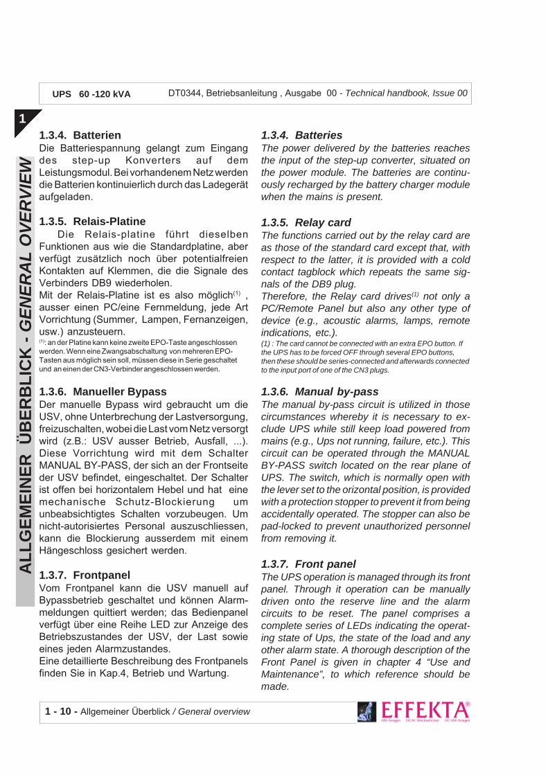
1.3.4. BatterienDie Batteriespannung gelangt zum Eingangdes step-up Konverters auf demLeistungsmodul. Bei vorhandenem Netz werdendie Batterien kontinuierlich durch das Ladegerätaufgeladen.
1.3.5. Relais-PlatineDie Relais-platine führt dieselben
Funktionen aus wie die Standardplatine, aberverfügt zusätzlich noch über potentialfreienKontakten auf Klemmen, die die Signale desVerbinders DB9 wiederholen.Mit der Relais-Platine ist es also möglich(1) ,ausser einen PC/eine Fernmeldung, jede ArtVorrichtung (Summer, Lampen, Fernanzeigen,usw.) anzusteuern.(1): an der Platine kann keine zweite EPO-Taste angeschlossenwerden. Wenn eine Zwangsabschaltung von mehreren EPO-Tasten aus möglich sein soll, müssen diese in Serie geschaltetund an einen der CN3-Verbinder angeschlossen werden.
1.3.6. Manueller BypassDer manuelle Bypass wird gebraucht um dieUSV, ohne Unterbrechung der Lastversorgung,freizuschalten, wobei die Last vom Netz versorgtwird (z.B.: USV ausser Betrieb, Ausfall, ...).Diese Vorrichtung wird mit dem SchalterMANUAL BY-PASS, der sich an der Frontseiteder USV befindet, eingeschaltet. Der Schalterist offen bei horizontalem Hebel und hat einemechanische Schutz-Blockierung umunbeabsichtigtes Schalten vorzubeugen. Umnicht-autorisiertes Personal auszuschliessen,kann die Blockierung ausserdem mit einemHängeschloss gesichert werden.
1.3.7. FrontpanelVom Frontpanel kann die USV manuell aufBypassbetrieb geschaltet und können Alarm-meldungen quittiert werden; das Bedienpanelverfügt über eine Reihe LED zur Anzeige desBetriebszustandes der USV, der Last sowieeines jeden Alarmzustandes.Eine detaillierte Beschreibung des Frontpanelsfinden Sie in Kap.4, Betrieb und Wartung.
1.3.4. BatteriesThe power delivered by the batteries reachesthe input of the step-up converter, situated onthe power module. The batteries are continu-ously recharged by the battery charger modulewhen the mains is present.
1.3.5. Relay cardThe functions carried out by the relay card areas those of the standard card except that, withrespect to the latter, it is provided with a coldcontact tagblock which repeats the same sig-nals of the DB9 plug.Therefore, the Relay card drives(1) not only aPC/Remote Panel but also any other type ofdevice (e.g., acoustic alarms, lamps, remoteindications, etc.).(1) : The card cannot be connected with an extra EPO button. Ifthe UPS has to be forced OFF through several EPO buttons,then these should be series-connected and afterwards connectedto the input port of one of the CN3 plugs.
1.3.6. Manual by-passThe manual by-pass circuit is utilized in thosecircumstances whereby it is necessary to ex-clude UPS while still keep load powered frommains (e.g., Ups not running, failure, etc.). Thiscircuit can be operated through the MANUALBY-PASS switch located on the rear plane ofUPS. The switch, which is normally open withthe lever set to the orizontal position, is providedwith a protection stopper to prevent it from beingaccidentally operated. The stopper can also bepad-locked to prevent unauthorized personnelfrom removing it.
1.3.7. Front panelThe UPS operation is managed through its frontpanel. Through it operation can be manuallydriven onto the reserve line and the alarmcircuits to be reset. The panel comprises acomplete series of LEDs indicating the operat-ing state of Ups, the state of the load and anyother alarm state. A thorough description of theFront Panel is given in chapter 4 “Use andMaintenance”, to which reference should bemade.

Installation / Installation 2 - 1
INS
TAL
LA
TIO
N -
IN
STA
LL
AT
ION
2
DT0344, Betriebsanleitung , Ausgabe 00 - Technical handbook, Issue 00UPS 60 -120 kVA
Inhalt
2.1. Einleitung ...................................... 32.1.1.Haftung ................................................ 32.1.2.Warenempfang .................................... 42.1.3.Produktbestimmung ............................ 42.1.4.Auspacken ........................................... 42.1.5.Einlagerung ......................................... 62.1.6.Aufstellung am Betriebsstandort ......... 72.1.7.Elektro-Verteilung der USV ................. 7
2.2. Netzanschluss der USV ................ 82.2.1.Vorbereitung des dreiphasigen
Versorgungsnetzes .............................. 92.2.2.Klemmen-Anschlüsse ........................ 102.2.3.Anschluss der Verbraucher ............... 12
2.3. Anschluss an externeVorrichtungen.............................. 14
2.3.1.Anschluss der Taste für die Not-Ausschaltung (E.P.O.) ....................... 14
2.3.2.Anschluss mit dem PC ...................... 15
2.3.3.Anschluss der Fernmeldung ............. 16
2.4. Relais-Platine (optional) ............. 17
2 - INSTALLATION 2 - INSTALLATION
Rev Descrizione Data Controllato Realizzato Data
Approvato
Tipo di doc. Pagine n° Pag. totali
Cod.
Table of contents
2.1. Introduction ................................... 32.1.1.Limitations of liability............................ 32.1.2.Material admittance ............................. 42.1.3.Identification ........................................ 42.1.4.Packing material removal .................... 42.1.5.Storing ................................................. 62.1.6.Siting it in the operative position ......... 72.1.7.UPS distribution panel ......................... 7
2.2. UPS connection to mains ............ 82.2.1.Setting up the three-phase primary
supply mains ........................................ 92.2.2.Tagblock wiring .................................. 102.2.3.User connection................................. 12
2.3. External devicesconnection .................................. 14
2.3.1.Emergency Power Off (E.P.O.) push-button connection .............................. 14
2.3.2.Connection to PersonalComputer ........................................... 15
2.3.3.Remote Panel connection ................. 16
2.4. Relay card (optional) .................. 17
U.T.
DT0344-DE00
1 0 / 1 0 /2003

2 - 2 - Installation / Installation
INS
TAL
LA
TIO
N -
IN
STA
LL
AT
ION
2
DT0344, Betriebsanleitung , Ausgabe 00 - Technical handbook, Issue 00UPS 60 -120 kVA
2.5. Provisorischer Anschluss für dieWiederaufladung der Batterie .... 18
2.5.1.Prüfungen und Einstellungen ............ 182.5.2.Verkabelung....................................... 19
2.5. Temporary connection to enablebattery recharge.......................... 18
2.5.1.Tests and setting options................... 182.5.2. Wiring................................................ 19

Installation / Installation 2 - 3
INS
TAL
LA
TIO
N -
IN
STA
LL
AT
ION
2
DT0344, Betriebsanleitung , Ausgabe 00 - Technical handbook, Issue 00UPS 60 -120 kVA
2.1. EINLEITUNG
Diese Anleitung enthält alle notwendigemechanische und elektrische Angaben für diekorrekte Installation der USV.
Dieses Kapitel enthält somit die Prozedurenfür richtiges Auspacken, für die Aufstellungund, anschliessend, Verkabelung und Anschlussder Anlage.
DIE IN DIESER ANLEITUNGBESCHRIEBENEN PROZEDUREN DÜRFENNUR DURCH ELEKTRIKER ODERQUALIFIZIERTES TECHNISCHES PERSONALDURCHGEFÜHRT WERDEN.
2.1.1. Haftung
Der Hersteller lehnt jede Haft fürFolgeschäden an Sachen oder Personen,die durch falsche Verbindungen oder nichtausdrücklich beschriebene Handlungenverursacht wurden, vollumfänglich ab.
2.1. INTRODUCTION
To properly install UPS all information con-cerning its mechanical and electrical interfacingis supplied inside this manual.
This section reports all the procedures re-quired to properly unpack the material, to site itand afterwards to properly wire-connecting it.
ALL THE OPERATIONS DESCRIBED IN THISMANUAL MUST BE EXECUTED BY AUTHOR-IZED ELECTRICIANS OR BY QUALIFIEDTECHNICAL PERSONNEL.
2.1.1. Limitations of liability
The constructor shall not be liable forconsequential damages to the equipment orperson based on wrong connections or op-erations non specifically set forth.

2 - 4 - Installation / Installation
INS
TAL
LA
TIO
N -
IN
STA
LL
AT
ION
2
DT0344, Betriebsanleitung , Ausgabe 00 - Technical handbook, Issue 00UPS 60 -120 kVA
2.1.2. Warenempfang
Bei der Lieferung überprüfen Sie dass keineTransportschäden vorliegen; nach sorgfältigerPrüfung der Verpackung überprüfen Sie denInhalt auf einwandfreien Zustand.
Anschliessend kontrollieren Sie dass dasgelieferte Material mit der Beschreibung desLieferscheines übereinstimmt.
2.1.3. Produktbestimmung
Die gelieferten Anlagensind durch ein selbstklebendesTypenschild auf derAnlagenrückseite, dass Modellund Leistung der USV-Anlageangibt, gekennzeichnet.
Das Auspacken derAnlage, d.h. korrektes Ent-fernen Transportverpackungder Anlagen, wird nun imFolgenden beschrieben.
2.1.4. Auspacken
Beachten Sie hierbei die Angaben auf derVerpackung (FRAGILE, OBEN), damit eineBeschädigung der USV-Anlage vermieden wird.
Um die Verpackung zu entfernen, gehenSie wie folgt vor (siehe Fig. 2.1):
- Unter Beachtung der Angaben auf derVerpackung (OBEN, UNTEN), platzierenSie die Anlage auf den Fussboden.
- Entfernen Sie Deckel und Seitenteile desHolzverschlages.
USV Typenschild - UPS Label
2.1.2. Material admittance
When receiving the material check for dam-ages that it might have suffered during transpor-tation. Therefore, properly inspect the packingcase and after having removed the packingmaterial check that the contents are in perfectcondition.
Afterwards ascertain that the material sup-plied is as that reported on the freight bill.
2.1.3. Identification
The equipment supplied is provided with anadhesive identification labelplaced on the UPS rear panelreporting type of UPS modeland power.
The cases utilized to transportthe equipment must be un-packed as specified by the pro-cedure stated below.
2.1.4. Packing material removal
During this operation observe the indica-tions (FRAGILE, UP) printed on the case toavoid damaging the UPS.
To remove the packing material proceed inthe following manner (see Fig. 2.1):
- place the equipment on the floor as in-structed on the outer case (UP, DOWN).
- Remove the cover and the side parts of thewooden crate.
Mod.KVAIn
OutImax CE

Installation / Installation 2 - 5
INS
TAL
LA
TIO
N -
IN
STA
LL
AT
ION
2
DT0344, Betriebsanleitung , Ausgabe 00 - Technical handbook, Issue 00UPS 60 -120 kVA
Fig. 2.1 - Entfernen der Verpackung der USV Packing removal from UPS
a) aufrecht auf den Boden stellen, unterBeachtung der OBEN/UNTEN-Angabenplace it properly on the floor observing theUP/DOWN indications
d) mit einem Gabelstapler das Gerät auf denBoden abstellenuse a forklift truck to place UPS on the floor
b) Vorsichtig die Verpackungsteile entfernen.Remuve the board,carefully.
c) Polyäthylen-Schutzfolie entfernen.remove the polyethylene.

2 - 6 - Installation / Installation
INS
TAL
LA
TIO
N -
IN
STA
LL
AT
ION
2
DT0344, Betriebsanleitung , Ausgabe 00 - Technical handbook, Issue 00UPS 60 -120 kVA
- Entfernen Sie die Schutzfolie womit dasGerät umwickelt ist.
- Mit einem Gabelstapler vorsichtig die USVvon unten aufnehmen, nur wenig anhebenund vorsichtig auf den Boden abstellen. DieUSV ist mit Räder ausgerüstet die einmüheloses Versetzen erlauben.
- Wir empfehlen das Verpackungsmaterialaufzuheben; es wird dann von Nutzen seinwenn die Anlage wieder verpackt werdenmuss (z.B.: bei Rückgabe, bei einschickenan die Servicestelle, bei einem Umzug).
- Vergewissern Sie sich dass das Gerät nichtbeschädigt ist, ansonsten benachrichtigenSie sofort den Wiederverkäufer.
2.1.5. Einlagerung
Wenn die Anlage nicht sofort installiert wird,muss diese an einen feuchte- undwärmegeschützten Ort eingelagert werden(zwischen +0 und +40 °C Raumtemperatur undweniger als 95% RH, nicht kondensierend).
Wenn eine Batterie im Lieferumfangenthalten ist, stellen Sie ausserdem sicher,dass bis zur nächsten Batterie-wiederaufladung nicht mehr als 6 Monatevergehen. Spätestens dann muss die USVprovisorisch angeschlossen und für dieerforderliche Wiederaufladezeit eingeschaltetwerden.Siehe hierzu Kap. 2.5 - Provisorischer Anschlussfür die Wiederaufladung der Batterie.
- Remove the cellophane wrapping utilizedas protection packing.
- Slide the forks of the lift truck under the UPSand after having lifted it a few centimetersfrom the floor, back up and lay it down. UPSis provided with wheels to easily move itaround.
- Do not throw away the packing material inthat it might be used again to repack theequipment if having to send it back or tosend it to maintenance centers or for re-moval purposes.
- Check that the equipment has not beendamaged. If otherwise immediately contactthe Sales Representative.
2.1.5. Storing
Should the equipment not be installed im-mediately it must be stored in a room so as toprotect it against excessive humidity and againstvery high heat sources i.e., +5° to +40°C, andhumidity not lower than 95% and moistureless.
If battery cubicle is supplied, make sure thatnot more than 6 months pass from the timethe battery had last been recharged.
After such period temporarily connect the UPSto mains and activate it for the time required torecharge the batteries.
Refer to para. 2.5 – Temporary connection toenable battery recharge.

Installation / Installation 2 - 7
INS
TAL
LA
TIO
N -
IN
STA
LL
AT
ION
2
DT0344, Betriebsanleitung , Ausgabe 00 - Technical handbook, Issue 00UPS 60 -120 kVA
2.1.6. Aufstellung am Betriebsstandort
Die USV ist mit Räder ausgerüstet und erlaubeneinfaches Platzieren am meist geeignetenAufstellungsort; dieser gewährt:- bequemer Anschluss,- ausreichender Freiplatz für Bedienung und
regelmässige sowie ausserordentlicheWartungseinsätze,
- ausreichende Belüftung für die Aufnahmeund den Abtransport der USV-Verlustwärme
- Schutz vor Umwelteinflüssen,- Schutz vor hoher Luftfeuchte oder starken
Wärmequellen,- Schutz vor Staub,- Beachtung der gültigen Brandschutz-
Vorschriften,- Betriebstemperatur zwischen +20 und
+25°C: bei dieser Temperatur haben dieBatterien den höchsten Wirkungsgrad.
2.1.7. Elektroverteilung der USV
Nachfolgend die Anordnung von Schalter undAnschlüsse.
2.1.6. Siting it in the operative position
The UPS is fitted with wheels so as to easilymove it to the right place. The place chosenmust guarantee:- easy connection;- enough space to easily work on UPS ,
considering also troubleshooting and cor-rective maintenance operations;
- interchange of air sufficient enough to dis-pel heat produced by UPS;
- protection against atmospheric agents;- protection against excessive humidity and
very high heat sources;- protection against dust;- compliance with the current fire prevention
norms.- operative environment temperature within
+20° C and +25° C. The batteries are atmaximum efficiency in this temperaturerange.
2.1.7. UPS distribution panel
The following figure illustrates the switches andplugs arranged on UPS.
Externe Anschlüsse(a) = Anschlussklemmen Eingangsnetz U1-V1-W1-N1(b) = Anschlussklemmen Bypassversorgung:U3-V3-W3-N3(c) = Ausgangsklemmen U2-V2-W2-N2(d) = Erdungsschiene (GND)(e) = Anschlussklemmen Batterieschrank
Gerätebezeichnungen(1) = Eingangsnetzschalter(2) = Eingangsschalter Bypassversorgung(3) = Schalter für den manuellen Bypass(4) = Ausgangsschalter (zur Last)(5) = Erdungsschiene(6) = Batterie-Sicherungstrenner
Devices description(1) = Input mains MCB(2) = ReserveInput MCB(3) = Manual By-pass MCB(4) = UPS Output MCB (to load)(5) = GND bar(6) = Battery fuses
(1) (2) (3) (4)
(5)
(a) (b) (c)
(d)
(e)
(6)
External connections(a) = Input mains terminal blocks U1-V1-W1-N1(b) = Reserve line terminal blocks U3-V3-W3-N3(c) = Output terminal blocks U2-V2-W2-N2(d) = GND busbar(d) = Ext. Battery terminal blocks

2 - 8 - Installation / Installation
INS
TAL
LA
TIO
N -
IN
STA
LL
AT
ION
2
DT0344, Betriebsanleitung , Ausgabe 00 - Technical handbook, Issue 00UPS 60 -120 kVA
2.2. NETZANSCHLUSS DER USV
Zur gewährung eines korrekten Betriebesder USV samt Zusatzeinrichtungen, müssengeeignete Schutzeinrichtungen sowohl in derVersorgungsleitung wie in der Lastleitungvorgesehen werden.
Die zu erstellenden Verbindungen werdenin Fig. 2.2 schematisch angezeigt.
DIE IM FOLGENDEN BESCHRIEBENEN AR-BEITEN DÜRFEN NUR DURCH ELEKTRIKERODER QUALIFIZIERTES TECHNISCHES PER-SONAL DURCHGEFÜHRT WERDEN.
Fig. 2.2 - Prinzipschema der Installation für die USVUPS installation schematic
Netz 380÷415VAC/50 Hz 3P+N+PE (GND)mains 380÷415 Vac/50 Hz 3ph+N+PE (GND)
USV Bypass-Schalter (normalerweise offen)UPS By-pass switch (normally open)
zum
Ver
brau
cher
-T
o u
sers
Thermo-magnetischer Schalter(1) “Kurve C”Magnetothermic switch (1) “Curve C”
Thermo-magnetischer Schalter(1) “KurveC” Magnetothermic switch “Curve C”
(1) = Vierpoliger Thermo-magnetischer Differentialschalter für pulsierenden Wechselstrom mit Gleichstromanteil,
gekennzeichnet durch die Symbole . Die minimale Schaltschwelle muss 500 mA betragen.a.c. four-pole safety magnetothermic switch, push-button with dc component,
distinguished by symbol . The minimum time to intervene must be 500 mA.
2.2. UPS CONNECTION TO MAINS
To guarantee that the UPS and relativeoptional equipment operate properly a mainspoint must be provided both at the input andoutput of the equipment which must also beprovided with the specific protection devices.
The wiring connections to be executed areshown in Fig. 2.2
THE OPERATIONS DESCRIBED IN THE FOL-LOWING PARAGRAPHS MUST BE CAR-RIED OUT BY AUTHORIZED ELECTRICIANSOR BY TECHNICAL PERSONNEL.
UPS

Installation / Installation 2 - 9
INS
TAL
LA
TIO
N -
IN
STA
LL
AT
ION
2
DT0344, Betriebsanleitung , Ausgabe 00 - Technical handbook, Issue 00UPS 60 -120 kVA
2.2.1. Vorbereitung des dreiphasigenVersorgungsnetzes
Vor Anschlusss der USV kontrollieren Siedass:
- die Netzdaten (Spannung und Frequenz)mit den Daten des Leistungsschildes an derUSV-Rückseite übereinstimmen(Eingangsspannung und -frequenz);
- die Anlagenerdung genau entsprechendden IEC- oder gültigen örtlichen Vorschriftenerstellt wurde.
Anschliessend installieren Sie eingangs-und ausgangsseitig die vierpoligen thermo-magnetischen Schalter (siehe Fig. 2.2) mitfolgenden Daten:
- Leistung gleich oder grösser als die aufdem Leistungsschild der USV angegebeneLeistung (KVA);
- Auslöse-Karakteristik entsprechend CEI-Normen oder gültigen örtlichen Vorschriftenfür thermo-magn. Schalter “Kurve C”.
- Die Verbindungsleitungen müssenausreichende Überlänge aufweisen, damitdie USV, für seitliche und rückseitigeZugänglichkeit bei Wartungsarbeiten, ummindestens 80cm verschoben werden kann.
2.2.1. Setting up the three-phase pri-mary supply mains
Before connecting the UPS check that:
- the mains voltage and frequency values areas those indicated on the adhesive labelattached on the rear plane of the UPS (inputvoltage, working frequency);
- plant grounding fully complies either withIEC norms or local laws.
Afterwards, start installing the four-polemagnetothermic switches both at the input andoutput of the UPS (see Fig. 2.2). The switchesfeature:
- capacity equal or greater than that reportedon the label situated on the UPS rear plane(KVA);
- characteristics compliant either with IECnorms or local laws for “Curve C”magnetothermic switches.
- Connecing cables must have a suitablelenght to allow the cubicle to advance atleast 80cm, for lateral and back accessibil-ity in case of mantainance.

2 - 10 - Installation / Installation
INS
TAL
LA
TIO
N -
IN
STA
LL
AT
ION
2
DT0344, Betriebsanleitung , Ausgabe 00 - Technical handbook, Issue 00UPS 60 -120 kVA
2.2.2. Klemmenanschlüsse
DIE BESCHRIEBENEN ARBEITEN DÜRFENNUR DURCH ELEKTRIKER ODERQUALIFIZIERTES TECHNISCHES PERSO-NAL DURCHGEFÜHRT WERDEN.
Für alle Verbindungen Kabelquerschnittegemäss Tabelle auf Seite 2-9 verwenden.
Für die Sicherheit des installierendenPersonals stellen Sie sicher dass für dieAnschlussarbeiten folgende Bedingungengewährleistet sind:- Netzversorgungsspannung abgeschaltet;- Verbraucher ausgeschaltet;- USV vollständig ausgeschaltet.
Um die USV vollständig auszuschalten:a) die Schalter für Netzeingang (1),
Reserveleitung (2) und Ausgang (4) öffnen,b) Batteriesicherungstrenner (5) öffnen
c) BYPASS-Schalter (3) öffnen.
1) Türe öffnen und die untereSchutzabdeckung entfernen.
2) Die Erdleitung von der Hauptverteilungan der Erdungsschiene anschliessen.
2.2.2. Tagblock wiring
THE OPERATIONS DESCRIBED IN THEPARAGRAPHS THAT FOLLOW MUST BECARRIED OUT BY AUTHORIZED ELECTRI-CIANS OR BY TECHNICAL PERSONNEL.
Use section cables as described in page 2-9.As far as the installation personnel’s
safety is concerned, make sure that the wiringoperations are carried out under the followingconditions:- primary mains voltage cut off;- users cut-off;- UPS fully de-activated.
To fully deactivate the UPS:a) open the main power switch (1),the reserve
line switch (2), the output switch (4) bysetting the lever to the down position
b) open the battery switch (5) by setting thelever to the down position;
c) open the BY-PASS switch (3) by setting thelever it to the down position.
1) Open the door and remove the lowerprotection panel
2) Connect the ground lead, incoming fromthe main distribution panel, to the GNDbusbar of the cubicle.
(1) (3)(2) (4)
(5)

Installation / Installation 2 - 11
INS
TAL
LA
TIO
N -
INS
TAL
LA
TIO
N
2
DT0344, Betriebsanleitung , Ausgabe 00 - Technical handbook, Issue 00UPS 60 -120 kVA
3) Der Schutzleiter der Lastversorgung andie Erdungsschiene der USVanschliessen.
4) Die Kabel des Eingangsnetzes,entsprechend Bild unten, an denKlemmen des Schalters I1 anschliessen.
5) Die Kabel der Lastversorgung an denKlemmen des Schalters I4 anschliessen.
6) Die Kabel der Res.-Versorgung an denKlemmen des Schalters I3 anschliessen.
7) Die Kabel des Batterieschrankes an denKlemmen der Trennsicherungenanschliessen.
Fig. 2.3 - Anschlüsse an den Klemmen der USVWiring on the UPS tagblock
11 12 13 14
1 = Netzeingang Phase U1 Input phase2 = Netzeingang Phase V1 Input phase3 = Netzeingang Phase W1Input phase4 = Netzeingang Nullleiter Input neutral5 = Res.-Eingang Phase U1Input reserve6 = Res.-Eingang Phase V1Input reserve7 = Res.-Eingang Phase W1Input reserve8 = Res.-Eingang Nullleiter Input neutral
9 = Pluspol Batterie Battery positive10 = Minuspol Batterie Battery negative11 = Ausgang Phase U2 Output phase12 = Ausgang Phase V2 Output phase13 = Ausgang Phase W2 Output phase14 = Ausgang Nullleiter Output neutral15 = Schutzerdung GND Ground
ANSCHLUSSKLEMMEN DER USV UPS TAGBLOCK
Verbraucher-SchutzleiterGround lead towards users an dieser Schiene den
Schutzleiter der USV-Netz-Einspeisung anschliessen
Onto this terminal connectthe ground lead incomingfrom the UPS input mainspower supply
(U2) (V2) (W2) (N2)
ErdungGround
NetzeingangMains input
USV Ausgang UPS output
Eingang Reservenetzreserve input
Batterie-Eingang battery input
(U1) (V1) (W1) (N1) (U3) (V3) (W3) (N3)
(+) (-)
1 2 3 4 5 6 7 8
9 10
(15)
Die empfohlene Kabel-Querschnitte werden inder Tabelle auf Seite 2-9angegeben.Die Bezugsnormen fürKabeldimensionierungsind: VDE 0100 Teil 3 undUNEL 35024170Use section cables asdescribed in the table ofpag.2-9.The referencenorms adopted for thedimensions of thecables are: VDE 0100part 3 andUNEL 35024170
3) Connect ground for utilities to the UPS GND busbar .
4)Connect mains cables to isolator I1terminal blocks , as indicated on figure.
5) Connect load cables to isolator I4 terminal blocks.6) Connect reserve mains cables to isolator I3 terminal bloks7)Connect cables from battery cubicle to isolating fuses terminals

2 - 12 - Installation / Installation
INS
TAL
LA
TIO
N -
INS
TAL
LA
TIO
N
2
DT0344, Betriebsanleitung , Ausgabe 00 - Technical handbook, Issue 00UPS 60 -120 kVA
2.2.3. Anschluss der Verbraucher
Es wird empfohlen am Ausgang der USV einvierpoliger thermo-magnetischer Schalter “KurveC” vorzusehen (siehe Fig. 2.2 und 2.4).
DIE BESCHRIEBENEN ARBEITEN DÜRFENNUR DURCH ELEKTRIKER ODERQUALIFIZIERTES TECHNISCHES PERSO-NAL DURCHGEFÜHRT WERDEN.
Für die Anschlussarbeiten müssen folgendeBedingungen gewährleistet sein:- Netzversorgungsspannung abgeschaltet;- Verbraucher ausgeschaltet;- USV vollständig ausgeschaltet.
Fig. 2.4 - Ausgangsverteilung VerbraucherLoad distribution Panel
2.2.3. User connection
Its suggested to connect a four-pole “Curve C”magnetothermic switch at the output of the UPS(see Fig. 2.2 and Fig. 2.4).
THE OPERATIONS DESCRIBED IN THEPARAGRAPHS THAT FOLLOW MUST BECARRIED OUT BY AUTHORIZED ELECTRI-CIANS OR BY TECHNICAL PERSONNEL.
The wiring operations must be carried out underthe following conditions:- primary mains voltage cut off;- users cut-off;- UPS fully de-activated.
SteckdoseVerbr. 1
Usersocket 1
SteckdoseVerbr. 2
Usersocket 2
SteckdoseVerbr. n
Usersocket n
thermo-magn.Fi-Schalter 1safetymagnetothermic 1
thermo-magn.Fi-Schalter 2safetymagnetothermic 2
thermo-magn.Fi-Schalter ...nsafetymagnetothermic ..n
4-poliger thermo-magn. Fi-Schalter “Kurve C”four-pole “Curve C”magnetothermic switch
VERBRAUCHERANSCHLUSS-VERTEILUNGLOAD DISTRIBUTION PANEL
VERBRAUCHER1 -USER 1
VERBRAUCHER2 -USER 2
VERBRAUCHER-n /USER-n
Durch Befestigender Kabel an derZugentlastungsschiene unterhalbder Schalter werden diese an derUSV verankert.
The bar near the switch blocks can beused to fasten the cable to the UPSthrough cable clamps.

Installation / Installation 2 - 13
INS
TAL
LA
TIO
N -
INS
TAL
LA
TIO
N
2
DT0344, Betriebsanleitung , Ausgabe 00 - Technical handbook, Issue 00UPS 60 -120 kVA
- Das Kabel der Lastversorgung an denKlemmen “15” (Erde), “11-12-13” (Phase)und “14” (Nullleiter) des thermo-magn.Fi-Schalters “KurveC” in der“Verbraucher-Verteilung” anschliessen.
Die Ausgänge des Schalters “Kurve C” müssenParallel an den Verbraucher-Steckdosenverdrahtet werden; wir empfehlen dieseVerbindungen ebenfalls mit thermo-magn. Fi-Schaltern auszuführen, je ein Schalter proSteckdose: die Schalter erlauben es, wennnotwendig, die einzelnen Verbraucherfreizuschalten.
Die Daten der vor den Verbrauchern zuinstallierenden Schalter, sowie die betr.Kabelquerschnitte, sind abhängig von dervorgesehenen jeweiligen Belastung.
Nach beenden der Anschlussarbeiten mussdie Schutzabdeckung der Anschlussklemmenwieder angebracht werden.
Anschliessend stellen Sie die USV an dergeeignetsten Stelle auf.
- Connect the UPS output cable to termi-nals “15” (ground), “11-12-13” (phase)and “14” (neutral) of the “Curve C”magnetothermic switch on the “User Dis-tribution Panel”.
Outputs of the “Curve C” switch must be parallel-connected to the user sockets; it is suggested toset up this link using other safety magnetothermicswitches, one per socket: the magnetothermicswitches will, if necessary, isolate each singleuser.
The characteristics of the magnetothermicswitches, to insert at the user input, and thecable sections are based on the loads applied tothe various sockets.
At the end of every connection, assembly againthe protection panel on the UPS tagblock.
Place UPS into the position considered mostfitting for the use .

2 - 14 - Installation / Installation
INS
TAL
LA
TIO
N -
INS
TAL
LA
TIO
N
2
DT0344, Betriebsanleitung , Ausgabe 00 - Technical handbook, Issue 00UPS 60 -120 kVA
2.3. ANSCHLUSS AN EXTERNEVORRICHTUNGEN
An der Rückseite der USV befindet sich derZugang zu einer Relais-Platine für den Anschlusseiner externen Not-Aus-Taste (E.P.O.=Emergency Power Off).Ausserdem befindet sich darauf auch einen DB9-Verbinder womit die USV mit einem PC verbundenwerden kann.Eine Klemmleiste auf der Platine erlaubt es, dieUSV mit einer Fernmeldung zur Fern-Anzeigeder Betriebszustände zu verbinden.
2.3.1. Anschluss der Taste für die Not-Ausschaltung (E.P.O.)
1) Das zwei-polige Verbindungskabel (Leiter-Querschnitt 0,6 mm2) darf nicht länger als100 m sein.
2) Das Kabel mit einem Öffner-Kontakt (NC)einer Pilztaste verbinden (Fig. 2.5).
3) Das andere Ende des Kabels mit der Relais-Platine verbinden (Fig. 2.5).
NOTA: die USV kann mit einer weiteren Relais-Platine (optional)ausgerüstet werden und somit sowohl mit einer Fernmeldung wieeinem PC verbunden werden. Es ist hingegen nicht möglich andieser Karte eine zweite EPO-Taste anzuschliessen. MehrereEPO-Tasten müssen seriegeschaltet werden und an einen dervorhandenen CN3-Verbinder angeschlossen werden.
Fig. 2.5 - Anschluss der E.P.O.-Taste - E.P.O. connection
N.C.= Öffner-KontaktNormally Closed
E.P.O.-TasteE.P.O. pushbutton
2.3. EXTERNAL DEVICES CON-NECTION
A Relay card is situated on UPS rear panel.Through this card UPS is connected to apushbutton whose function is of forcing UPSOFF should an emergency condition arise (E.P.O.= Emergency Power Off).Through plug DB9 the card can establish con-nection with UPS to a Personal Computer.Throught tag-block on it is possible to connectUPS to a remote panel for UPS status indica-tions.
2.3.1. Emergency Power Off (E.P.O.)push-button connection
1) Get a suitably long (not more than 100 m.)two-pole cable (0.6sq.mm conductor sec-tion)
2) Terminate one end of the cable to the N.C.pins of a fire preventing button (Fig. 2.5).
3) connect the other end of the cable toRelay card (Fig. 2.5).
NOTE: Another Relè card (optional) can be mounted on UPShence connecting it both to the remote panel and to the PC. Thecard cannot be fitted with an additional EPO button. To connectseveral EPO buttons to UPS first connect them in series and thenconnect the lot to one of the CN3s available.
Relais-Platinerelay-card
○ ○ ○ ○ ○ ○ ○ ○ ○ ○ ○ ○ ○

Installation / Installation 2 - 15
INS
TAL
LA
TIO
N -
INS
TAL
LA
TIO
N
2
DT0344, Betriebsanleitung , Ausgabe 00 - Technical handbook, Issue 00UPS 60 -120 kVA
2.3.2. Anschluss mit dem PC
Die Signalschnittstelle der Zephyr erlaubtdie Überwachung des Betriebszustandes derUSV mittels PC. Sobald sich Fehlzuständeeinstellen, werden diese detailliert auf dem PC-Bildschirm dargestellt.
Für die Verbindung verwenden Sie bitteausschliesslich das im Lieferumfang derGenerex-Software enthaltene Spezialkabel. DieSoftware mit Zubehör wird auf Verlangen alsOptional geliefert.1) Das Steckerende des Kabels mit dem
entspechenden DB9-F Verbinder der USVund das andere Ende gemäss nachfolgenderSkizze mit einem seriellen Anschluss desPC verbinden.
2) Einrichten der Einstellungen wie im Kap.4.2.4, Voreinstellungen, beschrieben.
2.3.2. Connection to Personal Compu-ter
The signals interface equipping UPS moni-tors the state of UPS with the Personal Compu-ter. Any failures present will be fully displayed onthe PC.
To set up this connection use the cablesupplied with the Generex software. The soft-ware together with the relative kit are optionallysupplied on Customer demand.
1) Connect the male connector tipped end tothe corresponding DB9 female connectoron UPS and the other end to a serial port onthe PC as shown below.
2) Preset as specified at para. 4.2.4 in the Set-up chapter.
zum seriellen PC-Anschluss
To the PC serial port
DB9-FVerbinderDB9 femaleconnector

2 - 16 - Installation / Installation
INS
TAL
LA
TIO
N -
INS
TAL
LA
TIO
N
2
DT0344, Betriebsanleitung , Ausgabe 00 - Technical handbook, Issue 00UPS 60 -120 kVA
Fig. 2.6 - Verdrahtungsschema Verbindungskabel FernmeldungDrawing showing Remote Panel wiring cable
Bypass EIN - By pass ON
Klemmleiste (USV-seitig)Tagblock (UPS side)
Klemmleiste (USV-seitig)Tagblock (panel side)
Querschnitt 0,6 mm2 , L max. = 100 m0.6 sq.mm. section max. L. = 100 m.
12
4
9
12
Netz vorhanden - mains ON
USV in Betrieb - UPS ON
Batterie entladen - Low batteryGem. Rückleitung - Common
15
4
3
2
LOW BATTERY
ON BYPASS
ALARM SILENCE
POWER ON
2.3.3. Remote Panel connection
The remote signalling panel is provided with apower supply unit.Proceed to assemble a connecting cable up butnot longer than 100m as shown in Figure 2.6.
2.3.3. Anschluss der Fernmeldung
Das Fernmeldepanel ist mit einer Speisungausgerüstet.Erstellen Sie ein Kabel geeigneter Länge, bis zumax. 100 m, entsprechend der Skizze Fig. 2.6.
Morsettiera M1M1 Tag-block

Installation / Installation 2 - 17
INS
TAL
LA
TIO
N -
INS
TAL
LA
TIO
N
2
DT0344, Betriebsanleitung , Ausgabe 00 - Technical handbook, Issue 00UPS 60 -120 kVA
Fig. 2.7 - Anschlussschema der Schnittstelle Relaisplatine Signals interface with relay card wiring diagram
2.4. RELAISPLATINE(OPTIONAL)
Auf Anfrage kann eine weitere Relaisplatine alsErweiterung der Standard-Platinegeliefertwerden. (1).
1) Erstellen Sie die Verbindungen gemässSchema der Fig. 2.7.
2) Führen Sie die Jumper-Voreinstellung wieim Kap. 3 beschrieben, aus.
(1): Es ist nicht möglich an dieser Relaisplatine eine zweite EPO-Taste anzuschliessen. Wenn mehrere EPO-Tasten angeschlossenwerden müssen, müssen diese seriegeschaltet werden und aneinen der vorhandenen CN3-Verbinder angeschlossen werden.
2.4. RELAY CARD (OPTIONAL)
A Relay card is supplied upon customer de-mand. This card can be added to the Relè one(1).
1) Proceed to wire-connect as shown on thediagram of Fig. 2.7.
2) Strap preset as reported in the Set up chap-ter
(1) : The Relay card cannot be fitted with an additional EPObutton. To connect several EPO buttons to UPS first connectthem in series and then connect the lot to one of the CN3savailable.
Klemmen für den E.P.O.-Anschluss (siehe Fig. 2.5)
E.P.O. wiring terminals (seeFig. 2.5) COM.
N.O.
N.C.
COM.N.O.
N.C.
COM.N.O.
N.C.
COM.N.O.
N.C.
DB9-Verbinder für denAnschluss an einem PC
(siehe Kap. 2.3.2)DB9 plug for Personal
Computer connection (seepara. 2.3.2)
Klemmen für Anschluss der USVUPS connection tagblock
Klemmen für die potentialfreienKontakten, zur freien Kunden-verwendung (Anschluss einerFernmeldung siehe Kap. 2.3.3)Tagblock with cold contacts freefor the User (Remote Panelconnection see para. 2.3.3)
BATTERIE ENTLADENBATTERY FLAT
NETZ VORHANDENMAINS PRESENCE
BY- PASS INSERITOBY-PASS ON
USV IN BETRIEBUPS RUNNING
Legende - Legend:N.O. = Schliesser - Normally openCOM.= Gemeinsam - CommonN.C. = Öffner - Normally Closed

2 - 18 - Installation / Installation
INS
TAL
LA
TIO
N -
INS
TAL
LA
TIO
N
2
DT0344, Betriebsanleitung , Ausgabe 00 - Technical handbook, Issue 00UPS 60 -120 kVA
2.5. PROV. ANSCHLUSS FÜR DIEWIEDERAUFLADUNG DERBATTERIE
DIE IM FOLGENDEN BESCHRIEBENEN AR-BEITEN DÜRFEN NUR DURCH ELEKTRIKEODER QUALIFIZIERTES TECHNISCHESPERSONAL DURCHGEFÜHRT WERDEN.
2.5.1. Prüfungen und Einstellungen
Bevor Sie die USV anschliessen, prüfenSie:
1) Netzspannung und Frequenz: diese müssenmit den Angaben auf dem Typenschild aufder Rückseite der USV übereinstimmen(Eingangsspannung und Frequenz);
2) die Leistung des thermo-magn. Schalters:diese muss gleich oder grösser als dieAngabe auf dem USV-Typenschild sein(kVA);
3) die Erdung der Anlage: diese muss den IEC-Normen oder den örtlichen Vorschriften völligentsprechen.
Für die Sicherheit des installierendenPersonals prüfen Sie dass für dieAnschlussarbeiten folgende Bedingungengewährleistet sind:
- Netzversorgungsspannung abgeschaltet;
- USV vollständig ausgeschaltet.
Um die USV vollständig auszuschalten:
a) Hauptschalter (1), Reserveleitung (2) undAusgangsschalter (4) öffnen (SchalthebelHorizontal);
2.5. TEMPORARY CONNECTIONTO ENABLE BATTERY RE-CHARGE
THE OPERATIONS DESCRIBED IN THEPARAGRAPHS THAT FOLLOW MUST BECARRIED OUT BY AUTHORIZED ELECTRI-CIANS OR BY TECHNICAL PERSONNEL.
2.5.1. Tests and setting options
Before wire-connecting the UPS, check:
1) the mains voltage and frequency values:these must correspond to thoseindicated on the adhesive label attached onthe rear plane of the UPS (input voltage,working frequency);
2) magnetothermic switch capacity: must beequal or greater than that reported on thelabel situated on the UPS rear plane (KVA);
3) plant grounding: must fully comply eitherwith IEC norms or local laws.
As far as the installation personnel’ssafety is concerned, make sure that the wiringoperations are carried out under the followingconditions:
- primary mains voltage cut off;
- UPS fully de-activated.
To fully deactivate the UPS:
a) open the main power switch (1),the reserveline switch (2), the output switch (4) by set-ting the lever to the horizontal position
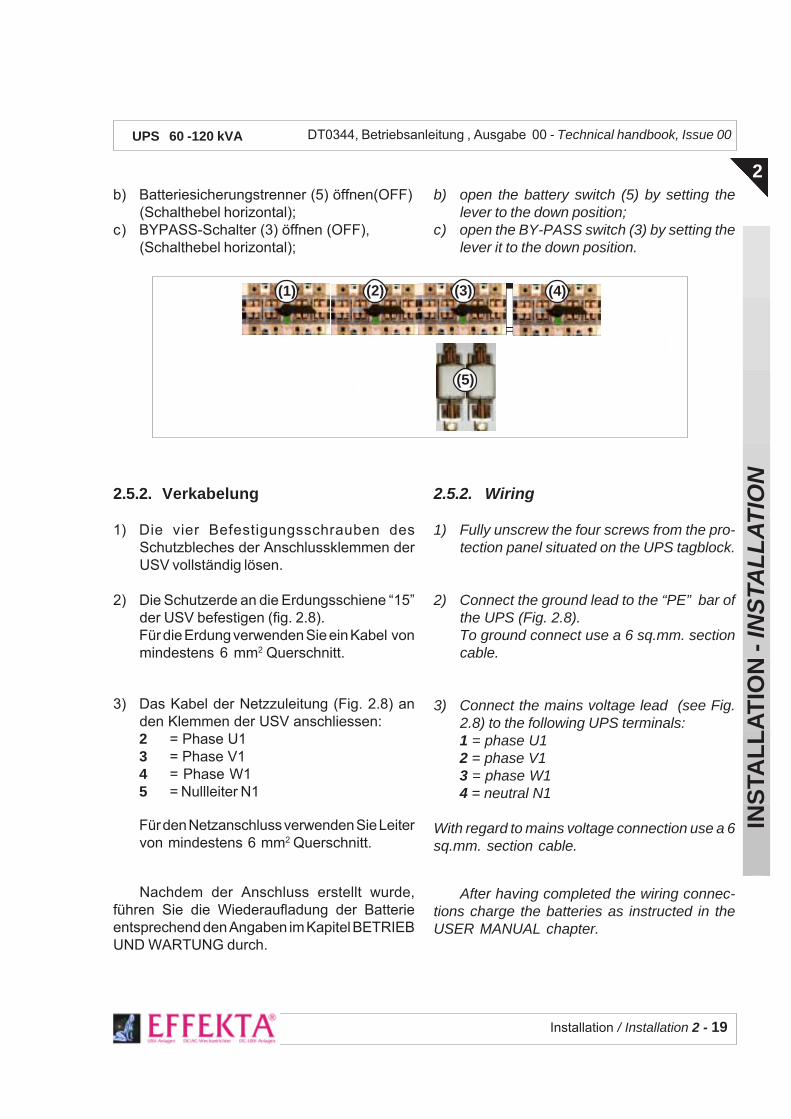
Installation / Installation 2 - 19
INS
TAL
LA
TIO
N -
INS
TAL
LA
TIO
N
2
DT0344, Betriebsanleitung , Ausgabe 00 - Technical handbook, Issue 00UPS 60 -120 kVA
b) Batteriesicherungstrenner (5) öffnen(OFF)(Schalthebel horizontal);
c) BYPASS-Schalter (3) öffnen (OFF),(Schalthebel horizontal);
2.5.2. Verkabelung
1) Die vier Befestigungsschrauben desSchutzbleches der Anschlussklemmen derUSV vollständig lösen.
2) Die Schutzerde an die Erdungsschiene “15”der USV befestigen (fig. 2.8).Für die Erdung verwenden Sie ein Kabel vonmindestens 6 mm2 Querschnitt.
3) Das Kabel der Netzzuleitung (Fig. 2.8) anden Klemmen der USV anschliessen:2 = Phase U13 = Phase V14 = Phase W15 = Nullleiter N1
Für den Netzanschluss verwenden Sie Leitervon mindestens 6 mm2 Querschnitt.
Nachdem der Anschluss erstellt wurde,führen Sie die Wiederaufladung der Batterieentsprechend den Angaben im Kapitel BETRIEBUND WARTUNG durch.
b) open the battery switch (5) by setting thelever to the down position;
c) open the BY-PASS switch (3) by setting thelever it to the down position.
2.5.2. Wiring
1) Fully unscrew the four screws from the pro-tection panel situated on the UPS tagblock.
2) Connect the ground lead to the “PE” bar ofthe UPS (Fig. 2.8).To ground connect use a 6 sq.mm. sectioncable.
3) Connect the mains voltage lead (see Fig.2.8) to the following UPS terminals:1 = phase U12 = phase V13 = phase W14 = neutral N1
With regard to mains voltage connection use a 6sq.mm. section cable.
After having completed the wiring connec-tions charge the batteries as instructed in theUSER MANUAL chapter.
(1) (3)(2) (4)
(5)

2 - 20 - Installation / Installation
INS
TAL
LA
TIO
N -
INS
TAL
LA
TIO
N
2
DT0344, Betriebsanleitung , Ausgabe 00 - Technical handbook, Issue 00UPS 60 -120 kVA
Fig. 2.8 - Prov. Anschluss für die Wiederaufladung der BatterieTemporary connection to enable battery recharge
1 2 3 4 5 6 7 8 11 12 13 1416 17 18
15
Netz 380÷415VAC/50 Hz - 3Ph+N+PE (GND)mains 380÷415 Vac/50 Hz 3PH+N+PE (GND)
Querschnitt-Section:6 mm2
PE (Schutzerde- gnd)PE (ground – gnd)
U1
V1
N1
(A) (B)
W1
ANSCHLUSSKLEMMEN DER USVUPS TAGBLOCK
9 10
1 = Netzeingang Phase U1 Input phase2 = Netzeingang Phase V1 Input phase3 = Netzeingang Phase W1Input phase4 = Netzeingang Nullleiter Input neutral5 = Res.-Eingang Phase U1 Input reserve6 = Res.-Eingang Phase V1 Input reserve7 = Res.-Eingang Phase W1Input reserve8 = Res.-Eingang Nullleiter Input neutral
9 = Pluspol Batterie Battery positive10 = Minuspol Batterie Battery negative11 = Ausgang Phase U2 Output phase12 = Ausgang Phase V2 Output phase13 = Ausgang Phase W2Output phase14 = Ausgang Nullleiter Output neutral15 = Schutzerdung GND Ground GND

Inbetriebsetzung / Setup 3 - 1
INB
ET
RIE
BS
ET
ZU
NG
- S
ET
UP
3
DT0344, Betriebsanleitung , Ausgabe 00 - Technical handbook, Issue 00UPS 60 -120 kVA
3 - INBETRIEBSETZUNG 3 - SETUP
Inhalt
3.1. Erst-Einschaltung u. Kontrollen .. 23.1.1.Anleitung für die Erst-Einschaltung
der USV.................................................23.1.2.Status-Prüfung der LED
des Frontpanels und der Anzeigen ........................................3
3.1.3.Belastungstest ......................................33.1.4.Funktionsprüfung der USV ....................43.1.5.Prüfung des Ladezustandes
der Batterie ..........................................43.1.6.Prüfung der Umschaltung der Last
auf Netz (automatischer Bypass) .........53.1.7.Funktionsprüfung des
manuellen Bypass ................................5
3.2. Voreinstellungen ........................... 63.2.1.Voreinstellungen auf d. Relaisplatine .....73.2.2.Voreinstellungen für d. Kommunikation
mit dem PC ...........................................8
3.3. Einrichten ext. Vorrichtungen ...... 93.3.1.Prüfung des Schaltkreises für die
Not-Aus Abschaltung (E.P.O.) ...............93.3.2.Prüfung der Fernmeldung ...................103.3.3.Prüfung der Fernsignalisierungen
der Relaisplatine .................................10
Rev Descrizione Data Controllato Realizzato Data
Approvato
Tipo di doc. Pagine n° Pag. totali
Cod.
Table of contents
3.1. Initial turn-on and checks ............. 23.1.1.UPS Initial turn-on
instructions ...........................................23.1.2.Check on the UPS status
of the front panel andsignalling ...............................................3
3.1.3.Load insertion test .................................33.1.4.UPS intervention test ............................43.1.5.Test on the battery charge
condition ................................................43.1.6.Test on switching over to the reserve line
(automatic by-pass) ..............................53.1.7.Manual By-pass
operation check ....................................5
3.2. Setting options .............................. 63.2.1 Setting options on the Relay card .........73.2.2.PC Interaction setting ...........................8
3.3. Pheripheral device set-up ............. 93.3.1.Check of the Emergency Power Off
circuit (E.P.O.).......................................93.3.2.Remote panel test ...............................103.3.3.Check on remote indications outputting
the Relay Card ....................................10
U.T.
DT0344-DE00
10/10/2003

3 - 2 - Inbetriebsetzung / Setup
INB
ET
RIE
BS
ET
ZU
NG
- S
ET
UP
3
DT0344, Betriebsanleitung , Ausgabe 00 - Technical handbook, Issue 00UPS 60 -120 kVA
3.1. ERST-EINSCHALTUNG UNDKONTROLLEN
3.1.1. Anleitung für die Erst-Einschaltung
Die Schalter für die Einschaltung der USVbefinden sich auf der Rückseite der Türe; inausgeschaltetem Zustand sind alleSchalthebel horizontal.
Bevor Sie die USV einschalten, kontrollieren Siedass der Schalter MANUAL BYPASSausgeschaltet und mechanisch blockiert ist (miteventuellem Hängeschloss).
Zum einschalten der USV betätigen Sie dieSchalter in der hier angegebenen Reihenfolge:
3.1. INITIAL TURN-ON ANDCHECKS
3.1.1. UPS Initial turn-on instructions
The ON/OFF switches of the UPS are situated inthe rear of the door and when in the OFFcondition the levers are all horizontal.
Before activating the UPS check that the lever ofthe MANUAL BY-PASS switch has been me-chanically locked (a safety padlock can be even-tually used).
Before activating the UPS operate the switchesfollowing the order given below:
1 - RESERVE INPUT-Schalter (I3) schliessen2 - UPS OUTPUT-Schalter (I4) schliessen
- Anlauf des Ventilators abwarten,d.h. Ausgangs-spannung vorhanden
3 - MAINS INPUT-Schalter (I1) schliessen4 - BATTERY-Trennschalter schliessen5 - Taste (1) "MENU" drücken6 - Menu "BEFEHLSMODUS" anwählen mit Tasten < (3) oder
> (4) und mit "ENTER" bestätigen (3 und 4 gleichzeitig)
7 - "INVERTER ON-OFF" anwählen mit Tasten <(3) oder >(4) und mit "ENTER" bestätigen (Tasten 3 und 4 gleichzeitig)
8 - Taste "CLEAR" drücken um das Menu "BEFEHLSMODUS"zu verlassen und sich im Anzeigemodus zu befinden.
Einschalt-Sequenz - Switching ON sequence:
1 – close the RESERVE INPUT switch (I3)2 – close the UPS OUTPUT switch (I4)
– wait the fan run, so the voltage is present to theoutput
3 – close the MAINS INPUT switch (I1)4 – close the battery isolator5 – press the "MENU" pushbutton (1)
6 – Choose the "COMMAND MODE " menu using the arrows
< (3) or > (4) and press "ENTER" (pushbuttons 3 and 4togheter )to confirm
7 – Choose "INVERTER ON-OFF" using the arrows <(3) or > (4) and press "ENTER" (pushbuttons 3 and 4togheter )to confirm
8 – Press "CLEAR" pushbutton to exit from "COMMANDMODE " menu to visualize the status and alarm menu

Inbetriebsetzung / Setup 3 - 3
INB
ET
RIE
BS
ET
ZU
NG
- S
ET
UP
3
DT0344, Betriebsanleitung , Ausgabe 00 - Technical handbook, Issue 00UPS 60 -120 kVA
3.1.2. Check on the status state of thefront panel and signalling LEDs
When switching ON, the UPS will set to theautomatic By-pass condition thus producing ageneric alarm (red LED glowing and buzzer alarmactivated).- Press the quenching key to clear the buzzer
alarm.After 20 seconds that the inverter has beenstarted the UPS will revert to the regular operat-ing conditions. This condition is indicated on thefront panel through the LCD above described.(fig.2.3)
3.1.3. Load insertion testDummy loads are suggested to be used tillreaching the maximum UPS power . With an eyeto the load indicating LEDs, gradually insert theload.WARNINGThe " Inverter Overload" alarm indicates that theUPS is overloaded (the load connected is toohigh): disconnect the load in excess, restart theinverter following the Inverter On-Off procedure.
3.1.2. Status-Prüfung der Anzeigen desLCD auf dem Frontpanel
Bei Einschalten der USV setzt diese sich inautomatischem Bypass wodurch ein allg. Alarmausgelöst wird (rotes LED leuchtet und Summertönt).- Drücken Sie die Quittiertaste "ESC" um den
akustischen Alarm abzustellen.Nach 20 sec setzt sich die USV in Normalbetrieb,welcher auf dem Frontpanel durch das obenbeschriebene LCD angegeben wird. (Fig. 2.3)
3.1.3. BelastungstestWir empfehlen die Verwendung von Kunstlastenum die Nennleistung der USV zu erreichen.Unter Beachtung der Belastungsanzeige desLCD (Parameter), erhöhen Sie Schrittweise dieLast.
ACHTUNGWenn das LCD "Überlast Inverter" anzeigt,bedeutet dies eine Überlastung der USV (dieangeschlossene Last ist zu gross): die Lastgenügend reduzieren, den Wechselrichter wiederstarten und die Alarmmeldung quittieren.
fig. 2.3
( 1 ) ( 2 )( 4 )( 3 )
( 5 )
( 6 )
( 7 )
Zustand des Frontpanels beiEinschalten der USV
Auf dem LCD (7) werden folgendeMeldungen angezeigt:
- USV in Betrieb -
- Inverter ein- Versorgungsnetz OK- Bypassnetz OK- Betteriespannung OK- Inverter und Bypass synchron- Last auf Inverter
Das grüne LED (5) leuchtet beiNormalbetrieb der USV.
Front panel status whenswitching ON the UPS
On LCD (7) will be displayed thefollowing statusi:
- UPS operating -
- inverter operating- mains line within limits- by pass line within limits- battery voltage within limits- inverter - bypass in syncro- load on inverter

3 - 4 - Inbetriebsetzung / Setup
INB
ET
RIE
BS
ET
ZU
NG
- S
ET
UP
3
DT0344, Betriebsanleitung , Ausgabe 00 - Technical handbook, Issue 00UPS 60 -120 kVA
3.1.4. Funktionsprüfung der USVDie Funktionsprüfung der USV und derUmschaltung Netz-/Batterie-Betrieb erfolgt durchAbschalten der Netzversorgung und Prüfungdass die Last weiterhin versorgt bleibt.Gehen Sie wie folgt vor:
3.1.5. Prüfung des Ladezustandes derBatterie
Während die Last nur durch die USV versorgtwird (Schalter INPUT MAINS offen), prüfen Sieauf dem LCD-Display die entsprechendenBatterieparameter (Vbatt, Ibatt, Autonomie%).
- Der Normalzustand liegt vor bei "Vbatt."zwischen 370 und 430Vdc und "Autonomie"bei 90...100% (Richtwerte je nach Belastung);
- der Zustand "Vorwarnung Autonomie-ende"liegt vor sobald "Vbatt." 350Vdc (+-2%)erreicht;
- der Zustand "Batterie nicht OK" (Unter-spannung) liegt vor, wenn der Wert "Vbatt."320Vdc (+-2%) beträgt.
3.1.4. UPS Mains failure testThe UPS intervention or MAINS/BATTERYswitching test is carried out by cutting off theinput mains and checking that the load is stillbeing powered.Proceed as stated below:
3.1.5. Test on the battery charge condi-tion
With the load powered through the UPS only(INPUT MAINS switch lever horizontal) checkon the LCD front panel the battery parameters (Vbatt, I batt, Back up time %).
- the normal condition is to have "Vbatt" be-tween 370-430Vdc and back up time between90-100% (indicative values depending on loadapplied);
- the BATTERY PREALARM condition is"Vbatt" between at 350Vdc (+-2%);
- the BATTERY VOLTAGE OUT OF LIMITScondition (minimum alarm) is "Vbatt" betweenat 320Vdc (+-2%);.
Funktionsprüfung - Intervention test1 - Schalter INPUT MAINS ausschalten und prüfen dass: 1 - Lower the INPUT MAINS switch lever and check that:
a - Alarmsummer ertönt a – the buzzer alarm is operatingb - rotes LED (6) ALARM leuchtet b – the red ALARM LED (6) is glowingc - LCD meldet Alarm "Versorgungsnetz nicht OK". c – alarm on LCD " mains line out of limits"
2 - Taste "ESC" (2) drücken um Alarmsummer abzustellen. 2 – Press "ESC" key (2) to clear the buzzer alarm.

Inbetriebsetzung / Setup 3 - 5
INB
ET
RIE
BS
ET
ZU
NG
- S
ET
UP
3
DT0344, Betriebsanleitung , Ausgabe 00 - Technical handbook, Issue 00UPS 60 -120 kVA
Bei weiterer Verwendung der Batterie erscheintdie Alarmmeldung "Ende Autonomie": der Inverterwird automatisch ausgeschaltet und die Anlagekann bis Rückkehr des Netzes nicht mehrgestartet werden.
3.1.6. Prüfung der Umschaltung der Lastauf Netz (automatischer Bypass)
Die Prüfung der Lastumschaltung wird durchauslösen einer Zwangsumschaltung desautomatischen Bypass durchgeführt untergleichzeitiger Kontrolle der Lastversorgung.
Wenn keine weitere Ereignisse eintreten, schaltetdie USV nach 20 sec wieder automatisch aufNormalbetrieb um.
3.1.7. Funktionsprüfung des manuellenBypass
Der manuelle Bypass erlaubt es, die USVfreizuschalten während die Last weiterhinversorgt bleibt. Zur Prüfung wie folgt vorgehen:1 - Taste (1) "MENU" drücken;2 - Menu "BEFEHLSMODUS" anwählen mit
Tasten < (3) oder > (4) und mit "ENTER"bestätigen (Tasten 3 und 4 gleichzeitig);
If the battery is further utilized, the alarm " BAT-TERY END OF DISCHARGING" will be dis-played : inverter is automatically stopped andthe UPS will not restartuntil mains will be restored
3.1.6. Test on switching over to the re-serve line (automatic by-pass)
The switching over to the reserve line test iscarried out by forcing the automatic By-passcircuit to intervene and by checking that the loadis still being powered.
If no other events arise, the UPS will automati-cally revert to regular operation after 20 sec-onds.
3.1.7. Manual By-pass operation check
The manual by-pass allows to exclude the UPSwhile still keeping the load powered. The check iscarried out in the following manner:1 -press the "MENU" pushbutton (1);2- Choose the "COMMAND MODE " menu
using the arrows < (3) or > (4) and press"ENTER" (keys 3 and 4 together )to confirm);
Umschaltung Last auf Bypassnetz Switching over to the reserve line
a - Taste (1) "MENU" drücken
b - Menu "BEFEHLSMODUS"anwählen mit Tasten < (3) oder >(4) und mit Taste "ENTER" bestätigen(Tasten 3 und 4 gleichzeitig).
c - "LASTUMSCHALTUNG"anwählen mit Tasten < (3) oder > (4)und mit Taste "ENTER" bestätigen(Tasten 3 und 4 gleichzeitig).
d - Taste "ESC" drücken um dasMenu Befehlsmodus zu verlassenund im Anzeigemodus zu kommen.
e - Rückkehr zu Normalbetrieb mitder Meldung auf LCD "Last aufInverter".
a – press the "MENU" pushbutton (1)
b – Choose the "COMMAND MODE "menu using the arrows < (3) or >(4) and press "ENTER" (pushbuttons 3and 4 togheter)to confirm
c – Choose "INVERTER ON-OFF"using the arrows < (3) or > (4) and press"ENTER" (pushbuttons 3 and 4togheter) to confirm
d – Press "ESC" pushbutton to exit from"COMMAND MODE " menu to visualizethe status and alarm menu
e – return to normal condition with LCDdisplay status "Load on Inverter".
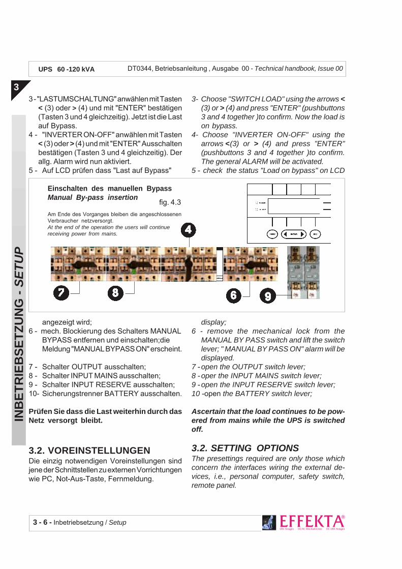
3 - 6 - Inbetriebsetzung / Setup
INB
ET
RIE
BS
ET
ZU
NG
- S
ET
UP
3
DT0344, Betriebsanleitung , Ausgabe 00 - Technical handbook, Issue 00UPS 60 -120 kVA
3 - "LASTUMSCHALTUNG" anwählen mit Tasten< (3) oder > (4) und mit "ENTER" bestätigen(Tasten 3 und 4 gleichzeitig). Jetzt ist die Lastauf Bypass.
4 - "INVERTER ON-OFF" anwählen mit Tasten< (3) oder > (4) und mit "ENTER" Ausschaltenbestätigen (Tasten 3 und 4 gleichzeitig). Derallg. Alarm wird nun aktiviert.
5 - Auf LCD prüfen dass "Last auf Bypass"
angezeigt wird;6 - mech. Blockierung des Schalters MANUAL
BYPASS entfernen und einschalten;dieMeldung "MANUAL BYPASS ON" erscheint.
7 - Schalter OUTPUT ausschalten;8 - Schalter INPUT MAINS ausschalten;9 - Schalter INPUT RESERVE ausschalten;10- Sicherungstrenner BATTERY ausschalten.
Prüfen Sie dass die Last weiterhin durch dasNetz versorgt bleibt.
3.2. VOREINSTELLUNGENDie einzig notwendigen Voreinstellungen sindjene der Schnittstellen zu externen Vorrichtungenwie PC, Not-Aus-Taste, Fernmeldung.
3- Choose "SWITCH LOAD" using the arrows <(3) or > (4) and press "ENTER" (pushbuttons3 and 4 together )to confirm. Now the load ison bypass.
4- Choose "INVERTER ON-OFF" using thearrows <(3) or > (4) and press "ENTER"(pushbuttons 3 and 4 together )to confirm.The general ALARM will be activated.
5 - check the status "Load on bypass" on LCD
display;6 - remove the mechanical lock from the
MANUAL BY PASS switch and lift the switchlever; " MANUAL BY PASS ON" alarm will bedisplayed.
7 -open the OUTPUT switch lever;8 -oper the INPUT MAINS switch lever;9 -open the INPUT RESERVE switch lever;10 -open the BATTERY switch lever;
Ascertain that the load continues to be pow-ered from mains while the UPS is switchedoff.
3.2. SETTING OPTIONSThe presettings required are only those whichconcern the interfaces wiring the external de-vices, i.e., personal computer, safety switch,remote panel.
Einschalten des manuellen BypassManual By-pass insertion
Am Ende des Vorganges bleiben die angeschlossenenVerbraucher netzversorgt.At the end of the operation the users will continuereceiving power from mains.
fig. 4.3

Inbetriebsetzung / Setup 3 - 7
INB
ET
RIE
BS
ET
ZU
NG
- S
ET
UP
3
DT0344, Betriebsanleitung , Ausgabe 00 - Technical handbook, Issue 00UPS 60 -120 kVA
3.2.1. Voreinstelleungen auf derRelaisplatine
Die Relaisplatine wird auf Verlangen als Optiongeliefert. Wenn diese vorhanden ist, muss dieseentsprechend der Einsatzart des Kundeneingestellt werden.Die Jumpereinstellungen für Einsatz mit PCoder Fernmeldung zeigt nachfolgende Tabelle.
3.2.1 Setting options on the Relay cardThe relay card is optionally supplied upon cus-tomer demand. If supplied the card shall have tobe preset according to specific Customer re-quirements.The strap configuration adopted for the applica-tion with PC or with the remote indication panel isdescribed in the following table.
Einsatz mit PC (seriell) J1,J2,J3,J5 J7, J8, J9, J10, J11,J14 Use with the PC serial
Relais-Platine - Relay Card
FUNKTION - FUNCTION VERBUNDEN - CLOSED OFFEN - OPEN
Einsatz mit PC (Kontakte) J5,J7,J8,J9,J10,J11,J14 J1, J2, J3, J4, J6 Use with the PC contact
Wenn der Anschluss einer Not-Aus-Taste für dieUSV (EPO) vorgesehen ist, müssen die Jumperwie folgt eingestellt werden:
Relaisplatine: Einstellung für E.P.O.Relay card : E.P.O. setting
When a connection with the E.P.O. of the UPSis established, the strap configuration reported inthe table below applies.
Jumperauf der RelaisplatineSetting options on the Relay card
FUNKTION VERBUNDEN OFFENFUNCTION CLOSED OPEN
EPO aktiv J15 J12, J16 EPO enabled
EPO nicht aktiv J12-J15 J16EPO not enabled

3 - 8 - Inbetriebsetzung / Setup
INB
ET
RIE
BS
ET
ZU
NG
- S
ET
UP
3
DT0344, Betriebsanleitung , Ausgabe 00 - Technical handbook, Issue 00UPS 60 -120 kVA
3.2.2. Voreinstellungen für dieKommunikation mit dem PC
Wie schon früher erwähnt, kann die USV einemComputer seinen Betriebszustand sowieMesswerten übermitteln. Diese Kommunikationkann zweierlei Arten sein: seriell fortgeschrittenoder seriell Grundstufe. Je nachdem welcheÜbermittlungsart mann zu verwenden gedenkt,also auch wie die USV-Firmware eingestelltwurde sowie welche Schnittstellenkarte an derUSV-Rückseite eingesetzt ist, muss bei derSoftware-Installation die entsprechende Zeile ausdem Roll-down-Menu ausgewählt werden. DieWerkseinstellung entspricht der komplettenVersion was in diesem Falle bedeutet dass beider Software-Version die Zeile "SQP3/3ph"gewählt werden sollte.Falls der Kunde auf Grund bestimmterBedingungen die "Grundstufe" einsetzen möchte,muss nach entsprechender Konfiguration derSchnittstellenkarte die Modell-Zeile "Basic CommxxKva/xxmin" bei der Software-Auswahlangewählt werden.(xx/xx=ihre Anlage)
3.2.2. PC Interaction settingoption
As explained before in this manual, UPS canbroadcast its status and its working measures.This communication can be of two levels: ad-vanced serial or basic serial. In dependance ofwhich you prefer, and therefore of how you setboth hardwere and firmware of the UPS, duringthe software installation you need to choose thecorrect item from UPS model list. When UPSfirst leaves the factory, it's setup for using thereachest communication, and this makes you tochoose "SQP3/3ph" as UPS model. In case thecustomer wpuld prefer using the basiccoominication, for special needs, while installingthe UPSMAN software he has to choose "BasicComm xxkVA/xxmin", where xx are values inaccordance with the model in your possession.

Inbetriebsetzung / Setup 3 - 9
INB
ET
RIE
BS
ET
ZU
NG
- S
ET
UP
3
DT0344, Betriebsanleitung , Ausgabe 00 - Technical handbook, Issue 00UPS 60 -120 kVA
3.3. EINRICHTEN EXTERNERVORRICHTUNGEN
Dieser Abschnitt enthält Anleitungen für diePrüfung externer an die USV angeschlossenerVorrichtungen wie die Not-Aus-Taste, der PCoder die Fernmeldung.
3.3.1. Prüfung des Schaltkreises für dieNot-Aus-Abschaltung (E.P.O.)
Der Schaltkreis wurde entwickelt um die USV inNot-Situationen abschalten zu können (Feuer,Wasser, ... usw.) und sieht eine externe Not-Taste mit Öffner-Kontakte vor, die an derRelaisplatine angeschlossen wird.Zur Prüfung der korrekten Funktion gehen Siewie folgt vor.ACHTUNG: wenn sich das oben beschriebeneVerhalten nicht einstellt, kontrollieren Sie dieJumper-Einstellungen auf der Relaisplatine (Kap.3.2.1).
3.3. PHERIPHERAL DEVICE SET-UP
This paragraph reports the instruction to befollowed when testing the external plants and theperipheral devices connecting UPS, i.e., thesafety ON/OFF switch, the PC, the remote panel.
3.3.1. Check of the Emergency Power Offcircuit (E.P.O.)
This circuit has been designed to switch off theUPS in emergency conditions (i.e., fire, flood,etc.). It utilizes an external safety switch with NCcontact connecting the Relay card .
To check that it operates correctly proceed asdescribed below.WARNING: If the above conditions are not veri-fied, check the straps on the Relay card (seeparas. 3.2.1).
Test der Not-Aus Abschaltung E.P.O. - Test of the E.P.O.-Switch
- Externes EPOa) Drücken Sie die externe Not-Aus-Taste: die USVschaltet innert 2 sec ab und unterbricht die Last-versorgung(akustischer Alarm, aufleuchten von Allg. Alarm)b) Zur Rückstellung die USV vollständig ausschalten undein paar Minuten abwarten (für die Wiedereinschaltungmuss das LCD zuerst völlig gelöscht sein).Zum Wiedereinschalten die Einschaltprozedurgemäss Kap. 3.1.1.wiederholen.
– Remote EPOa) Press the external "EMERGENCY"pushbutton: theUps switches off within 2 seconds and stopspowering the load [buzzer alarm and general alarmactivation].b) To reset switch off completely the UPS and wait fewminutes (to restart, wait the LCD completely switchedoff). To restart, please repeat the start up proce_dure described on paragraph 3.1.1 of the presentsection.
a)
b)

3 - 10 - Inbetriebsetzung / Setup
INB
ET
RIE
BS
ET
ZU
NG
- S
ET
UP
3
DT0344, Betriebsanleitung , Ausgabe 00 - Technical handbook, Issue 00UPS 60 -120 kVA
Prüfung der Fernmeldung - Remote panel test
1 - Simulieren Sie einen Netzausfall durch Ausschalten desSchalters INPUT MAINS auf der USV;
2 - prüfen Sie dass auf dem Fernmeldepanel das rote LEDRECTIFIER(4) aufleuchtet;
3 - verifizieren Sie dass der Alarmsummer der Fernmeldungertönt; nach Betätigen der Taste BUZZER wird derakustische Alarm quittiert.
1 - simulate mains absence by lowering the lever of theINPUT switch on the UPS;
2 - check that red LED RECTIFIER (4) light up on theremote indication panel;
3 - check that the buzzer alarm intervenes on the remotepanel; press the BUZZER key to quench the alarm.
3.3.2. Prüfung der FernmeldungZur Prüfung der korrekten Funktion gehen Sievor wie nachfolgend angegeben.
3.3.3. Prüfung der Fernsignalisierungender Relaisplatine
Auf der Klemmreihe M der Relaisplatine stehenpotentialfreie Umschaltkontakte zur Verfügungfür Meldung der USV-Zustände, entsprechendfolgender Tabelle (bei ausgeschalteter USV sinddie Öffnerkontakte aktiv).
Kontrollieren Sie die korrekte Zuordnung derMeldungen obiger Tabelle mit einem Tester durchMessung der Verbindung zwischengemeinsamer Pol und betr. Meldekontakte.
3.3.2. Remote panel testTo check regular operation proceed as statedbelow.
3.3.3. Check on remote indicationsoutputting the Relay Card
The M tagblock of the Relay card is provided withcold contacts of the NO/NC types concerningthe status of the UPS described in the tablebelow (when UPS is OFF the NC contacts mustshow continuity with the relative common lead).
Make sure that the relationship given is true bymeasuring with a tester the ohmic continuitybetween the common lead and the relativecontacts.
LOW BATTERY
ON BYPASS
ALARM SILENCE
POWER ON
Morsetti Segnalazioni
12 .................... USV in Betrieb (N.O.)11 .................... gemeinsam10 .................... USV Ausfall (N.C.)9 ..................... Bypass Ein (N.O.)8 ..................... gemeinsam7 ..................... Bypass Aus (N.C.)6 ..................... Netzausfall (N.O.)5 ..................... gemeinsam4 ..................... Netz vorhanden (N.C.)3 ..................... Batteriekapazitätausreichend (N.O.)2 ..................... gemeinsam1 ..................... Batterie entladen (N.C.)
Terminals Indications
12 .................... UPS running (N.O.)11 .................... common10 .................... UPS faulty (N.C.)9 ..................... By-pass enabled (N.O.)8 ..................... common7 ..................... By-pass disabled (N.C.)6 ..................... 230 VAC mains failure (N.O.)5 ..................... common4 ..................... 230 VAC mains presence (N.C.)3 ..................... Sufficient battery level (N.O.)2 ..................... common1 ..................... Battery flat (N.C.)

Betrieb und Wartung - User manual 4 - 1
BE
TR
IEB
UN
D W
AR
TU
NG
- U
SE
R M
AN
UA
L
4
DT0344, Betriebsanleitung , Ausgabe 00 - Technical handbook, Issue 00UPS 60 -120 kVA
4 - BETRIEB UND WARTUNG 4 - USER MANUAL
Inhalt
4.1. Allgemeine Beschreibung ............ 34.1.1.Betriebsarten .........................................44.1.2.Reservenetz(Automatischer Bypass) ...44.1.3.ManuellerBypass...................................4
4.2. Das Frontpanel.............................. 54.2.1.Taste MENU...........................................54.2.2.Taste ESC.............................................54.2.3.Tasten BACK und NEXT ........................64.2.4.Meldeleuchte NORMAL .........................74.2.5.Meldeleuchte ALARM ............................74.2.6.Menu Bedienpanel .................................7
4.3. Vorderseitiges Schaltfeld ........... 144.3.1. INPUT MAINS Schalter ........................144.3.2.RESERVE INPUT Schalter .................144.3.3.MANUAL BYPASS Schalter .................144.3.4.UPS OUTPUT Schalter ......................144.3.5.BATTERY Sicherungstrenner .............15
4.4. Betriebsanweisungen ................ 154.4.1.Einschalten der USV ...........................154.4.2.Ausschalten der USV ..........................164.4.3.Einschalten des manuellen Bypass
und Ausschalten der USV ohneUnterbruch der Lastversorgung ..........17
Table of contents
4.1. General overview .......................... 34.1.1.Operation ..............................................44.1.2.Automatic By-pass ...............................44.1.3.Manual By-pass....................................4
4.2. Front panel .................................... 54.2.1. "MENU" push-button ............................54.2.2. "ESC" push-button ................................54.2.3. "BACK" and "NEXT"push-button ..........64.2.4. "NORMAL" light ....................................74.2.5. "ALARM" light .......................................74.2.6.Control panel menu ...............................7
4.3. Front distribution panel .............. 144.3.1. INPUT MAINS switch .........................144.3.2.RESERVE INPUT switch ...................144.3.3.MANUAL BY-PASS switch .................144.3.4.UPS OUTPUT Switch .........................144.3.5.BATTERY fuses switch .......................15
4.4. User’s guide ................................ 154.4.1.UPS switching ON ..............................154.4.2.UPS switching-off ................................164.4.3.Manual by-pass connection and Qusar
switching OFF without cutting off powerto the load ...........................................17
Rev Descrizione Data Controllato Realizzato Data
Approvato
Tipo di doc. Pagine n° Pag. totali
Cod.
U.T. 10-01-2003
DT0344-DE00

4 - 2 - Betrieb und Wartung - User manual
BE
TR
IEB
UN
D W
AR
TU
NG
- U
SE
R M
AN
UA
L
4
DT0344, Betriebsanleitung , Ausgabe 00 - Technical handbook, Issue 00UPS 60 -120 kVA
4.4.4.Wiedereinschalten der USV undAusschalten des manuellen Bypassohne Unterbruch der Lastversorgung .18
4.4.5.Einschalten des manuellen Bypass beiAusfall der USV ...................................19
4.5. Einsatz mit dem PC..................... 20
4.6. Fernanzeige (optional) ............... 21
4.7. Ordentliche Wartung ................... 224.7.1.Funktionsprüfung der USV ..................224.7.2.Batterieladung .....................................224.7.3.Regelmässige Prüfung des
Reservenetzes....................................224.7.4.Reinigung von Gehäuse, Frontplatte und
des Luftfilters ......................................23
4.8. Regelmässige Wartung ............... 23
4.9. Betriebszustände der USV (Normalbetrieb) .......................... 24
4.10. Fehlersuche ................................ 26
4.4.4.Resetting UPS and disconnectingmanual by-pass without cutting off powerto the load ...........................................18
4.4.5.Manual by-pass connection followingUPS failure ..........................................19
4.5. Use with the PC........................... 20
4.6. Remote panel (optional) ............. 21
4.7. Routine maintenance .................. 224.7.1.Check on UPS intervention ................224.7.2.Battery recharge .................................224.7.3.Routine operating check on the reserve
line ......................................................224.7.4.Cabinet, Front panel and ventilation grid
cleaning ...............................................23
4.8. Periodic maintenance ................... 23
4.9. UPS status (normal operatingmode) ........................................... 25
4.10. Troubleshooting.......................... 27

Betrieb und Wartung - User manual 4 - 3
BE
TR
IEB
UN
D W
AR
TU
NG
- U
SE
R M
AN
UA
L
4
DT0344, Betriebsanleitung , Ausgabe 00 - Technical handbook, Issue 00UPS 60 -120 kVA
4.1. ALLG. BESCHREIBUNGDie USV-Anlage ist in einem Gehäuse mit
einer schönen und angenehm geformtenFrontseite untergebracht, an dessen Oberkantedas Frontpanel mit den Befehls- undAnzeigeelementen eingelassen ist.
An der Vorderseite, an gewollt versteckter Stellehinter der Türe zur Vermeidung zufälligerBetätigung, befinden sich die Hauptschalter. Ander Rückseite neben der Klemmleiste befindensich zwei, für DB9-Verbinder vorgesehene,Öffnungen. Der eine Standard- Verbinder wirdgebraucht für die Verbindung der USV mit einemPC. Ein auf Anfrage erhältlichesKommunikationsprogramm erlaubt es dieBetriebsfunktionen zu steuern. Der neben demVerbinder vorhandene Klemmensatz kannalternativ für den Anschluss einer Fernmeldungfür die Anzeige der Betriebszustände gebrauchtwerden (optional). Auf Anfrage kann eine weitereRelaisplatine mit den gleichen Funktionen derStandardplatine geliefert werden.Die USV bietet hohe Leistungen in SachenSicherheit, Schutz und Zuverlässigkeit und istsomit ideal für die Versorgung hochsensiblernetzgespiesener Apparaturen.
Vorderansicht - Front view
Fernmeldung - Remote Panel
4.1. GENERAL OVERVIEWUPS consist of a cabinet featuring a finely de-signed front coverplate with flowing line mountingthe command and indication panel.In the rear of the door are contained the various
operating switches, hidden from sight to preventthem from being accidentally operated.The two slots are reserved for a standard DB9connector used to connect UPS to a PC. TheConstructor supplied program residing on thePC allows to manage UPS operation. To thetagblock residing on the same board a remotepanel (optional) can be connected. The lightspresent on the remote panel reports on the UPSstate of operation.An additional Relay Board (optional) with func-tions similar to the standard one is supplied uponcustomer demand.UPS has been designed and constructed withthe aim of offering high performance in terms ofsafety, protection and reliability. UPS is there-fore, suitable to serve sophisticated loads whichare highly sensitive to surges and micro-inter-ruptions on the mains power.
Verbinder DB 9

4 - 4 - Betrieb und Wartung - User manual
BE
TR
IEB
UN
D W
AR
TU
NG
- U
SE
R M
AN
UA
L
4
DT0344, Betriebsanleitung , Ausgabe 00 - Technical handbook, Issue 00UPS 60 -120 kVA
4.1.1. BetriebsartenDie USV hat zwei typische Betriebsarten:- bei NETZBETRIEB, bei vorhandenem Netz,werden die angeschlossenen Verbraucher(Last)mit sauberer gefilterter Netzspannung versorgt;die Batterie ist in Ruhe und wird unter Ladunggehalten. Dies ist die normale Betriebsart.- bei BATTERIEBETIEB, bei fehlendem Netz,liefert die Batterie die für die Lastversorgungnotwendige Energie und stellt somit auch beiNetzausfall die Versorgung der Verbrauchersicher.Die Umschaltung NETZ/BATTERIE istautomatisch und unmittelbar bei Ausfall derNetzspannung; bei Netzrückkehr wird, ebenfallsautomatisch, zurückgeschaltet und derNormalbetrieb wiederhergestellt.
4.1.2. Reservenetz (AutomatischerBypass)
Bei Auftreten abnormaler Situationen (z.B. Ausfallder Batterie, interner Schaltkreise oder beiÜbertemperatur) wird der automatische Bypassaktiviert und vorübergehend das Reservenetzzuschalten; die Last wird somit weiterhin viaautomatischem Bypass mit Netzspannungversorgt. Sobald die Ursachen, die denautomatischen Bypass ausgelöst haben, nichtmehr vorhanden sind, wird dieser automatischausgeschaltet und die Last wieder durch dieUSV versorgt. Die Aktivierung desautomatischen Bypass wird auf dem Frontpaneldurch eine Meldelampe angezeigt.4.1.3. Manueller BypassDer manuelle Bypass ist ein Schaltkreis für alleFälle wobei die USV freigeschaltet werden mussunter Beibehalt der Lastversorgung (z.B.: USVausgeschaltet, ausgefallen, ...). DieseVorrichtung wird durch den Schalter MANUALBYPASS an der Anlagenvorderseite hinter derTüre, bedient.Der Schalterverfügt über eine Blockierung womitvor ungewollter Betätigung geschützt wird. Umden Gebrauch durch nicht-autorisiertes Perso-nal vorzubeugen, kann die Blockierung mit einemHängeschloss gesichert werden.
4.1.1. OperationThe dual operating modes of UPS are:- from MAINS, with mains present, the load iskept powered by the mains voltage which isfiltered and rectified by UPS; the battery is idleand constantly charged. This is the regular op-erating condition.- from BATTERY, with no mains voltagepresent, the battery yields the power required tosupply the load.In this manner power is guaranteed to the con-nected load even with no mains present.The switching over from MAINS to BATTERY isautomatic and immediately following mains fail-ure. Likewise, when mains is restored the equip-ment reverts to the regular operating condition.
4.1.2. Automatic By-pass
When UPS detects faulty conditions (e.g., bat-tery or circuitry failure, or excessive tempera-ture), an automatic switching circuit will auto-matically intervene to by-pass over to a tran-sient path. On this path the mains will continuepowering as long as the automatic switchingcircuit intervenes.When the cause for switching clears, the auto-matic switching circuit automatically cuts off andthe load is once again powered through UPS.The intervention of the automatic by-pass switchis signalled on the front panel through the turningon of the yellow light.
4.1.3. Manual By-passThe manual by-pass circuit is utilized in all thosecircumstances whereby UPS must be excludedwhile still keeping the load powered (e.g., UPSnot running, failure, etc.). This circuit can beoperated through the MANUAL BY-PASS switchsituated on UPS front ,opening the door.The switch is provided with a mechanical lockprotecting it against accidental operations. Themechanical lock can be further secured with apadlock. This latter measure is used to preventunauthorized personnel from removing it.
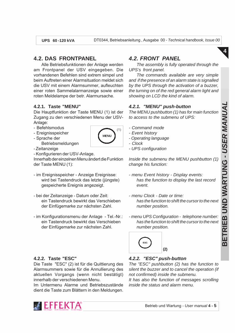
Betrieb und Wartung - User manual 4 - 5
BE
TR
IEB
UN
D W
AR
TU
NG
- U
SE
R M
AN
UA
L
4
DT0344, Betriebsanleitung , Ausgabe 00 - Technical handbook, Issue 00UPS 60 -120 kVA
4.2. FRONT PANELThe assembly is fully operated through the
UPS’s front panel.The commands available are very simple
and if the presence of an alarm state is signalledby the UPS through the activation of a buzzer,the turning on of the red general alarm light andshowing on LCD the kind of alarm.
4.2.1. "MENU" push-buttonThe MENU pushbutton (1) has for main functionto access to the submenu of UPS:
- Command mode- Event history- Operating language- Clock- UPS configuration
Inside the submenu the MENU pushbutton (1)change his function:
- menu Event history - Display events:has the function to display the last recordevent.
- menu Clock - Date or time:has the function to shift the cursor to the nextnumber position.
- menu UPS Configuration - telephone number:has the function to shift the cursor to the nextnumber position.
4.2.2. "ESC" push-buttonThe "ESC" pushbutton (2) has the function tosilent the buzzer and to cancel the operation (ifnot confirmed) inside the submenu.It has also the function of messages scrollinginside the status and alarm menu.
4.2. DAS FRONTPANELAlle Betriebsfunktionen der Anlage werden
am Frontpanel der USV eingegeben. Dievorhandenen Befehlen sind extrem simpel undbeim Auftreten einer Alarmsituation meldet sichdie USV mit einem Alarmsummer, aufleuchteneiner roten Sammelalarmanzeige sowie einerroten Meldelampe der betr. Alarmursache.
4.2.1. Taste "MENU"Die Hauptfunktion der Taste MENU (1) ist derZugang zu den verschiedenen Menu der USV-Anlage:- Befehlsmodus- Ereignisspeicher- Sprache der
Betriebsmeldungen- Zeitanzeige- Konfigurieren der USV-Anlage.Innerhalb der einzelnen Menu ändert die Funktionder Taste MENU (1):
- im Ereignisspeicher - Anzeige Ereignisse:wird bei Tastendruck das letzte (jüngste)gespeicherte Ereignis angezeigt.
- bei der Zeitanzeige - Datum oder Zeit:ein Tastendruck bewirkt das Verschiebender Einfügemarke zur nächsten Zahl.
- im Konfigurationsmenu der Anlage - Tel.-Nr.:ein Tastendruck bewirkt das Verschiebender Einfügemarke zur nächsten Zahl.
4.2.2. Taste "ESC"Die Taste "ESC" (2) ist für die Quittierung desAlarmsummers sowie für die Annullierung desaktuellen Vorgangs (wenn nicht bestätigt)innerhalb der verschiedenen Menu.Im Untermenu Alarme und Betriebszuständedient die Taste zum Blättern in den Meldungen.
(1)
(2)

4 - 6 - Betrieb und Wartung - User manual
BE
TR
IEB
UN
D W
AR
TU
NG
- U
SE
R M
AN
UA
L
4
DT0344, Betriebsanleitung , Ausgabe 00 - Technical handbook, Issue 00UPS 60 -120 kVA
Das Bedienpanel
Das Panel zeigt den Betriebszustandder USV-Anlage an
Control panel
The panel displays the equipment's operating state
4.2.3. Tasten "BACK" und "NEXT"Die Tasten Back (3) und Next (4) haben je nachUntermenu verschiedene Funktionen:
- Gleichzeitige Betätigung beiderTasten entspricht Eingabe desaktuellen Vorganges (Funktion"ENTER").
- im Menu Ereignisspeicher blättert man mitBack durch die Meldungen bei Anzeige vonnur Datum und Zeit; Next zeigt das mitDatum und Zeit ausgewählte Ereignis inkl.Alarme und Betriebszustände an.
- im Menu Sprache der Anzeige,werden mitBack und Next die vorhandenen SprachenSprachen angezeigt.
- In den Menu's Zeitanzeige und Tel. Nr.wirdmit der Taste Back die Zahl verringert undmit Next vergrössert.
4.2.3. "BACK" and "NEXT" pushbuttonsThe Back (3) and Next (4) pushbuttuons have
different functions depending ofsubmenu:
- Pressing togheter the pushbuttonsit is made the operation confirm("ENTER" function)
- Inside the Event History menu, Back scrollthe event date and time only; Next displaythe event set (date and time ) with the statusand alarm.
- inside the Operating language menu, Backand Next display the available languages.
- inside the Clock and Telephone numbermenus, Back increase the number, Nextdecrease the number to set.
(3) (4)
Legende der Befehlstasten und Meldeleuchten derZEPHYR
( 1 ) = Taste "MENU"( 2 ) = Taste "ESC"( 3 ) = Taste "BACK"( 4 ) = Taste "NEXT"(3) +(4) = Funktion "ENTER"( 5 ) = Grüne Lampe "NORMAL", leuchtet bei Normalbetrieb( 6 ) = Rote Lampe "ALARM", leuchtet in Alarmsituationen( 7 ) = alfanumerisches Display zur Anzeige der Funktionen
und USV-Parameter.
Legend of the commands and lights on the UPS
( 1 ) = "MENU" pushbutton( 2 ) = "ESC" pushbutton( 3 ) = "BACK" pushbutton( 4 ) = "NEXT" pushbutton(3) + (4) = "ENTER function( 5 ) = Green light, ON to indicate UPS normal operation( 6 ) = Red light, ON to indicate UPS general alarm( 7 ) = LCD display to display the UPS functions and
parameters.
( 1 ( 2( 4( 3
( 5
( 6
( 7

Betrieb und Wartung - User manual 4 - 7
BE
TR
IEB
UN
D W
AR
TU
NG
- U
SE
R M
AN
UA
L
4
DT0344, Betriebsanleitung , Ausgabe 00 - Technical handbook, Issue 00UPS 60 -120 kVA
4.2.4. "NORMAL" LIGHT
The green light inicates the UPS normalstatus.
4.2.5. "ALARM" LIGHT
This light it is on every time that an alarm orfault condition occur..
The turning on of this light is always associatedwith the activation of a buzzer which can be silentusing "ESC" pushbutton.
4.2.6 CONTROL PANEL MENU
The table below show the main menu levels"STATUS-ALARM MENU":inside this menu it is possible to see the statusand the operative conditions of the UPS, the"ESC" pushbutton has the function to scroll thedisplay status/alarm.From this menu the user can access to differentsubmenu by pressing "MENU" pushbutton(second level).Once on the second level, the first row show
4.2.4. MELDELEUCHTE "NORMAL"
Die grüne Meldeleuchte zeigt Normal-Betrieb derUSV an.
4.2.5. MELDELEUCHTE ALARM ALLG.
Diese leuchtet jeweils immer bei jeder Alarm-oder Fehlermeldung.Ein Aufleuchten ist immer mit einer AkustischenWarnung verbunden; der Summer lässt sich mitder Taste "ESC" abstellen.
4.2.6 MENU BEDIENPANEL
Das folgende Bild zeigt die Positionen desHauptmenüs "MENU ZUSTÄNDE - ALARME":In diesem Menu können die Betriebszuständeder USV angezeigt werden, mit der Taste "ESC"kann in der Anzeige Zustände/Alarme geblättertwerden.Von diesem Menu hat man Zutritt zu den diversenPositionen durch Betätigen der Taste "MENU"(zweite Ebene).Innerhalb der zweiten Ebene, lautet die erste
(6) ALARM(5) NORMAL
MENU ZUSTÄNDE - ALARME
USV-PARAMETER
BEFEHLSMODUS
EREIGNISSPEICHER
SPRACHE
UHR
USV KONFIGURIEREN
NEXT
NEXT
NEXT
NEXT
NEXT
STATUS - ALARM MENU
UPS PARAMETERS
COMMAND MODE
EVENT HISTORY
OPERATING LANGUAGE
CLOCK
UPS CONFIGURATION
NEXT
NEXT
NEXT
NEXT
NEXT

4 - 8 - Betrieb und Wartung - User manual
BE
TR
IEB
UN
D W
AR
TU
NG
- U
SE
R M
AN
UA
L
4
DT0344, Betriebsanleitung , Ausgabe 00 - Technical handbook, Issue 00UPS 60 -120 kVA
< menu choice > and using "NEXT" and "BACK"pushbuttons it is possible to choose the desiredmenu. Pressing "NEXT" and "BACK" pushbuttonat the same time the "ENTER" command isselected and the lower level will be reached. The"confirmed" on the display and a beep will indica-te the action occurred.Pressing "ESC" pushbutton it is possible to goback at the previous level.From "STATUS-ALARM MENU" pressing"NEXT" it possible to access at "UPSPARAMETERS"
Zeile < Menu-Auswahl > und mit den Tasten"NEXT" und "BACK" wird das gewünschte Menuangewählt. Durch gleichzeitige Betätigung derTasten "NEXT" und "BACK" wird der Befehl"ENTER" ausgeführt und man kommt in dernächst-tieferen Ebene des gewählten Menü's.Die Meldung "bestätigt" auf der Anzeige sowieein Ton des Summers bestätigen die Aktion.Durch Drücken der Taste "ESC" kommt manwieder zur vorherigen Ebene. Vom Menu"ZUSTÄNDE-ALARME" kommt man mit derTaste "NEXT" im Menu "USV-PARAMETER".
NEXT
MENU ZUSTÄNDE - ALARME
USV-PARAMETER
EINGANGSSPANNUNG L1-N L2-N L3-N
EINGANGSSPANNUNG L1-L2 L2-L3 L3-L1
AUSGANGSSPANNUNG L-N
EINGANGSSTROM I-r I-s I-t
AUSGANGSSTROM I-out
BATTERIE Vbatt -Ibatt -Autonomie %
FREQUENZ Fin Fout
TEMPERATUR T °C
AUSGANGSLEISTUNG kW kVA cosø
KONFIGURATION USV Vout Fout PS 1%
NEXT
NEXT
NEXT
NEXT
NEXT
NEXT
NEXT
NEXT
NEXT
NEXT
NEXT
STATUS - ALARM MENU
UPS PARAMETERS
INPUT VOLTAGEL1-N L2-N L3-N
INPUT VOLTAGEL1-L2 L2-L3 L3-L1
OUTPUT VOLTAGEL-N
INPUT CURRENTI-r I-s I-t
OUTPUT CURRENTI-out
BATTERYVbatt -Ibatt - Autonomy %
FREQUENCYFin Fout
TEMPERATURET °C
OUTPUT POWERkW kVA cosø
UPS SETTINGVout Fout PS 1%
NEXT
NEXT
NEXT
NEXT
NEXT
NEXT
NEXT
NEXT
NEXT
NEXT

Betrieb und Wartung - User manual 4 - 9
BE
TR
IEB
UN
D W
AR
TU
NG
- U
SE
R M
AN
UA
L
4
DT0344, Betriebsanleitung , Ausgabe 00 - Technical handbook, Issue 00UPS 60 -120 kVA
From < menu choice > it is possible choose oneof the following menu:
- COMMAND MODE : in this menu it ispossible to execute operative command on UPS.
a) Inverter ON-OFF is the commnad to start andstop the Inverter. In case of overload thiscommand reset the alarm condition and restartthe inverter.
b) Swicth load is the command for tranferring theoutput load (20sec.)on automatic bypass line.
This command it is also used to reset the StaticSwitch Locked condition (condition that happenfor high inrush current of the load on the inverterfor three times consecuitive).
c) Battery test is the manual command to verifythe battery. The command activate the controlcircuit of the battery that will verify the goodcondition.
Von < Auswahl Menü > kann eines der Unter-Menü angewählt werden:
- BEFEHLSMODUS: In diesem Menü könnenfolgende Betriebsbefehle der USV ausgeführtwerden.
a) Inverter ON-OFF ist der Ein- undAusschaltbefehl des Inverters. Bei Überlast erfolgteine Rückstellung der Alarmmeldung und gibteinen Inverter-Neustart frei.
b) Lastumschaltung ist der Befehl für diekurzzeitige Umschaltung der Last (20sec.) aufBypass.Dieser Befehl wird auch verwendet zurRückstellung des Warnzustandes StatischerSchalter blockiert (tritt ein nach dreimaligesAuftreten von Lastspitzen auf den Inverter).
c) Batterie-Test ist der manuelle Befehl zurPrüfung der Batterie. Der Befehl aktiviert denBatterie-Kontrollkreis und überprüft dessenZustand.
MENU ZUSTÄNDE - ALARME
BEFEHLSMODUS
INVERTER ON-OFF
ON- OFF Inverter
LASTUMSCHALTUNG
Schaltet die Last aufBypass um
BATTERIE-TEST
Man. Battery test
NEXT
NEXT
STATUS - ALARM MENU
COMMAND MODE
INVERTER ON-OFF
Start- Stop Inverter
SWITCH LOAD
Transfer load to bypass
BATTERY TEST
Battery test manual
NEXT
NEXT
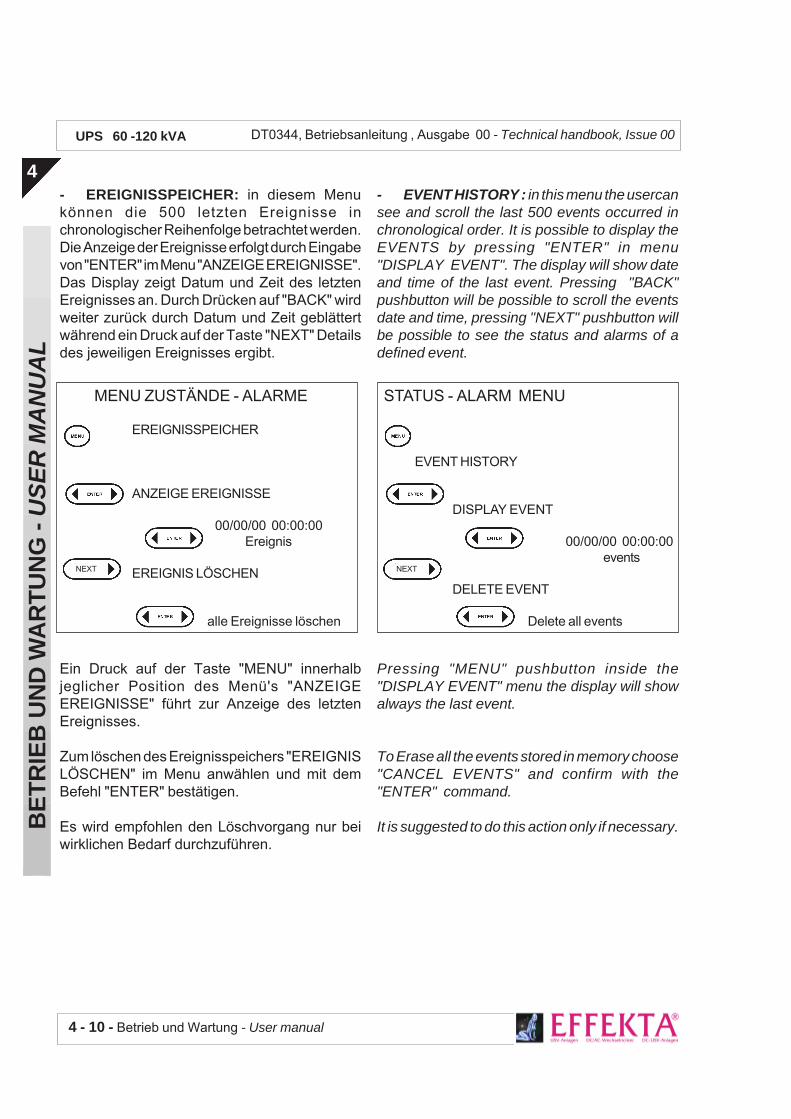
4 - 10 - Betrieb und Wartung - User manual
BE
TR
IEB
UN
D W
AR
TU
NG
- U
SE
R M
AN
UA
L
4
DT0344, Betriebsanleitung , Ausgabe 00 - Technical handbook, Issue 00UPS 60 -120 kVA
- EREIGNISSPEICHER: in diesem Menukönnen die 500 letzten Ereignisse inchronologischer Reihenfolge betrachtet werden.Die Anzeige der Ereignisse erfolgt durch Eingabevon "ENTER" im Menu "ANZEIGE EREIGNISSE".Das Display zeigt Datum und Zeit des letztenEreignisses an. Durch Drücken auf "BACK" wirdweiter zurück durch Datum und Zeit geblättertwährend ein Druck auf der Taste "NEXT" Detailsdes jeweiligen Ereignisses ergibt.
Ein Druck auf der Taste "MENU" innerhalbjeglicher Position des Menü's "ANZEIGEEREIGNISSE" führt zur Anzeige des letztenEreignisses.
Zum löschen des Ereignisspeichers "EREIGNISLÖSCHEN" im Menu anwählen und mit demBefehl "ENTER" bestätigen.
Es wird empfohlen den Löschvorgang nur beiwirklichen Bedarf durchzuführen.
- EVENT HISTORY : in this menu the usercansee and scroll the last 500 events occurred inchronological order. It is possible to display theEVENTS by pressing "ENTER" in menu"DISPLAY EVENT". The display will show dateand time of the last event. Pressing "BACK"pushbutton will be possible to scroll the eventsdate and time, pressing "NEXT" pushbutton willbe possible to see the status and alarms of adefined event.
Pressing "MENU" pushbutton inside the"DISPLAY EVENT" menu the display will showalways the last event.
To Erase all the events stored in memory choose"CANCEL EVENTS" and confirm with the"ENTER" command.
It is suggested to do this action only if necessary.
MENU ZUSTÄNDE - ALARME
EREIGNISSPEICHER
ANZEIGE EREIGNISSE
00/00/00 00:00:00Ereignis
EREIGNIS LÖSCHEN
alle Ereignisse löschen
NEXT
STATUS - ALARM MENU
EVENT HISTORY
DISPLAY EVENT
00/00/00 00:00:00events
DELETE EVENT
Delete all events
NEXT
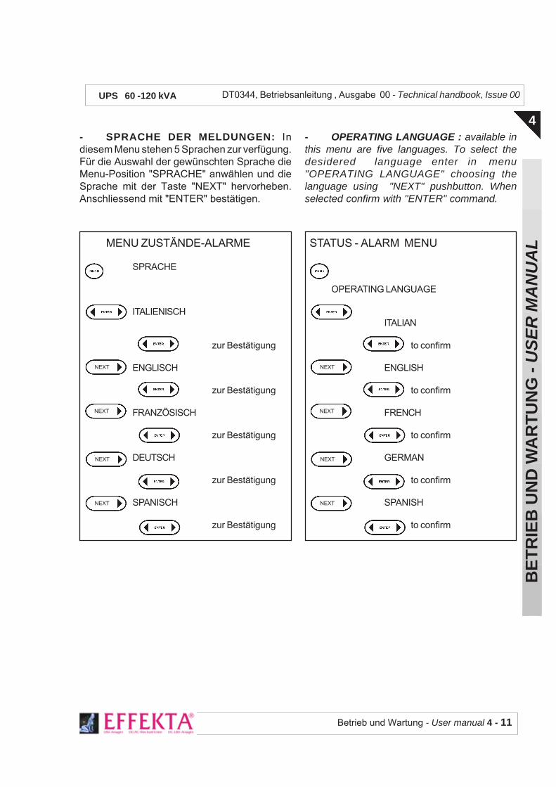
Betrieb und Wartung - User manual 4 - 11
BE
TR
IEB
UN
D W
AR
TU
NG
- U
SE
R M
AN
UA
L
4
DT0344, Betriebsanleitung , Ausgabe 00 - Technical handbook, Issue 00UPS 60 -120 kVA
MENU ZUSTÄNDE-ALARME
SPRACHE
ITALIENISCH
zur Bestätigung
ENGLISCH
zur Bestätigung
FRANZÖSISCH
zur Bestätigung
DEUTSCH
zur Bestätigung
SPANISCH
zur Bestätigung
NEXT
NEXT
NEXT
NEXT
STATUS - ALARM MENU
OPERATING LANGUAGE
ITALIAN
to confirm
ENGLISH
to confirm
FRENCH
to confirm
GERMAN
to confirm
SPANISH
to confirm
NEXT
NEXT
NEXT
NEXT
- SPRACHE DER MELDUNGEN: Indiesem Menu stehen 5 Sprachen zur verfügung.Für die Auswahl der gewünschten Sprache dieMenu-Position "SPRACHE" anwählen und dieSprache mit der Taste "NEXT" hervorheben.Anschliessend mit "ENTER" bestätigen.
- OPERATING LANGUAGE : available inthis menu are five languages. To select thedesidered language enter in menu"OPERATING LANGUAGE" choosing thelanguage using "NEXT" pushbutton. Whenselected confirm with "ENTER" command.
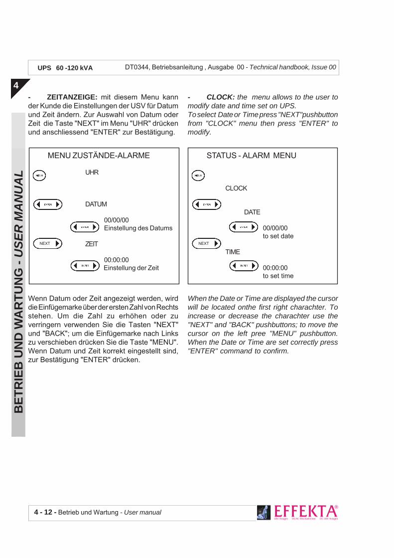
4 - 12 - Betrieb und Wartung - User manual
BE
TR
IEB
UN
D W
AR
TU
NG
- U
SE
R M
AN
UA
L
4
DT0344, Betriebsanleitung , Ausgabe 00 - Technical handbook, Issue 00UPS 60 -120 kVA
- ZEITANZEIGE: mit diesem Menu kannder Kunde die Einstellungen der USV für Datumund Zeit ändern. Zur Auswahl von Datum oderZeit die Taste "NEXT" im Menu "UHR" drückenund anschliessend "ENTER" zur Bestätigung.
Wenn Datum oder Zeit angezeigt werden, wirddie Einfügemarke über der ersten Zahl von Rechtsstehen. Um die Zahl zu erhöhen oder zuverringern verwenden Sie die Tasten "NEXT"und "BACK"; um die Einfügemarke nach Linkszu verschieben drücken Sie die Taste "MENU".Wenn Datum und Zeit korrekt eingestellt sind,zur Bestätigung "ENTER" drücken.
- CLOCK: the menu allows to the user tomodify date and time set on UPS.To select Date or Time press "NEXT"pushbuttonfrom "CLOCK" menu then press "ENTER" tomodify.
When the Date or Time are displayed the cursorwill be located onthe first right charachter. Toincrease or decrease the charachter use the"NEXT" and "BACK" pushbuttons; to move thecursor on the left pree "MENU" pushbutton.When the Date or Time are set correctly press"ENTER" command to confirm.
MENU ZUSTÄNDE-ALARME
UHR
DATUM
00/00/00Einstellung des Datums
ZEIT
00:00:00Einstellung der Zeit
NEXT
STATUS - ALARM MENU
CLOCK
DATE
00/00/00to set date
TIME
00:00:00to set time
NEXT

Betrieb und Wartung - User manual 4 - 13
BE
TR
IEB
UN
D W
AR
TU
NG
- U
SE
R M
AN
UA
L
4
DT0344, Betriebsanleitung , Ausgabe 00 - Technical handbook, Issue 00UPS 60 -120 kVA
- KONFIGURIEREN DER USV: mit demMenu können die USV-Parameter verändertwerden.Es wird strengstens dazu empfohlen diesesMenu nur durch geschultes Fachpersonalverwenden zu lassen.
In diesem Menü kann der Kunde lediglich dieKundendienst-Telefonnummer einfügen oderändern.Für den Zutritt "Telefonnummer" anwählen undzur Bestätigung "ENTER" drücken.Um die Zahl zu erhöhen oder zu verringernverwenden Sie die Tasten "NEXT" und "BACK";um die Einfügemarke nach Links zu verschiebendrücken Sie die Taste "MENU". Wenn dieTelefonnummer korrekt eingestellt ist, zurBestätigung "ENTER" drücken.
- UPS CONFIGURATION: the menu allowsto modify parameters of UPS.
It is strongly reccomended that only trainedpeople can access to this menu.
In this menu the user can only add or modify theservice phone number.
To select this menu choose "phone number" andpress "ENTER" to confirm.To increase or decrease the charachter use the"NEXT" and "BACK" pushbuttons; to move thecursor on the left pree "MENU" pushbutton.When the Date or Time are set correctly press"ENTER" command to confirm.
MENU ZUSTÄNDE-ALARME
USV-KONFIGURATION
SERIE-NUMMER
TELEFON-NUMMER
0000000000Einstellen der Tel.-Nr.
BATTERIE-KAPAZITÄT
EINSTELLEN DER PARAMETER
NEXT
NEXT
NEXT
STATUS - ALARM MENU
UPS CONFIGURATION
SERIAL NUMBER
PHONE NUMBER
0000000000to set service phone n.
BATTERY CAPACITY
CALIBRATION
NEXT
NEXT
NEXT

4 - 14 - Betrieb und Wartung - User manual
BE
TR
IEB
UN
D W
AR
TU
NG
- U
SE
R M
AN
UA
L
4
DT0344, Betriebsanleitung , Ausgabe 00 - Technical handbook, Issue 00UPS 60 -120 kVA
Das Schaltfeld der USV befindet sich, zur Vermeidungzufälliger Betätigung, an gewollt versteckter Stelle ander Anlagenvorderseite hinter der Türe.Es enthält alle Leistungs- und Steuerschalter der USV.
Legende der Schalter im Schaltfeld
( 1 ) = Netzeingangsschalter( 2 ) = Eingangsschalter Reservenetz( 3 ) = Schalter für den Man. Bypass( 4 ) = Ausgangsschalter für die Lastversorgung( 5 ) = Batterie-Sicherungstrenner
Legend of the switches present on the distribution panel
( 1 ) = Mains input switch( 2 ) = Reserve line switch( 3 ) = Manual By-pass switch( 4 ) = UPS output switch( 5 ) = Battery fuses switch
4.3. VORDERSEITIGESSCHALTFELD
4.3.1. INPUT MAINS SchalterMit diesem Schalter wird die USV am Eingangs-versorgungsnetz (380÷415VAC) ange-schlossen.
4.3.2. RESERVE INPUT SchalterDieser Schalter verbindet den statischen Schalterder USV mit dem Reservenetz (380÷415 VAC).
4.3.3. MANUAL BY-PASS SchalterNormalerweise ist der Schalter offen (Man.Bypass ausgeschaltet) und durch einemechanische Blockierung vor ungewollterBetätigung geschützt. Diese Schutzvorrichtungselbst kann durch ein Hängeschloss gesichertwerden. Wird in all jenen Fällen gebraucht wobei,unter Beibehalt der Lastversorgung(Netzversorgung), die USV freigeschaltet werdensoll.
4.3.4. OUTPUT SchalterDieser Schalter erlaubt es den Ausgang der USVmit der Last zu verbinden.
4.3. FRONT DISTRIBUTIONPANEL
4.3.1. INPUT MAINS switchThis switch connects the external power supplyline (380÷400 VAC) to UPS input port.
4.3.2. RESERVE INPUT switchThis switch connects the reserve line (380÷415VAC) to UPS static switch.
4.3.3. MANUAL BY-PASS switchThe switch is normally set to open position (By-pass excluded).The switch is protected against unintentionaloperations through a mechanical lock wich canbe additionally provided with a pad-lock for fur-ther protection. It is utilized in all those circum-stance whereby UPS has to be excluded whilestill keeping the load powered from mains.
4.3.4.UPS OUTPUT switchThis switch connects the UPS output to the load.
UPS distribution panel is situated on the front plane pur-posely hidden from sight to prevent unintentional or acciden-tal operations. It comprises all the switches used to activate/de-activate UPS.
(1) (2) (3) (4)(5)

Betrieb und Wartung - User manual 4 - 15
BE
TR
IEB
UN
D W
AR
TU
NG
- U
SE
R M
AN
UA
L
4
DT0344, Betriebsanleitung , Ausgabe 00 - Technical handbook, Issue 00UPS 60 -120 kVA
Einschaltsequenz
4.3.5. BATTERY SicherungstrennerVerbindet die Batterie mit den internenSchaltkreisen der USV. Dieser Sicherungs-trenner darf nicht unter Last betätigt werden undsomit nur bei offenem externen Batterieschaltergeöffnet oder geschlossen werden; erlaubt alsoein Freischalten der USV bei Wartungsarbeiten.
4.4. BETRIEBSANWEISUNGEN4.4.1. Einschalten der USVDie Schaltelemente der USV befinden sich allehinter der Türe und sind ausgeschaltet wenn derSchalthebel horizontal ist.Vor einschalten der USV kontrollieren Sie dassder Schalter MANUAL BYPASS ausgeschaltet(horizontal) und mechanisch blockiert ist (evtl.mit Hängeschloss).Um die USV einzuschalten, betätigen Sie dieSchalter in der angegebenen Reihenfolge:ACHTUNG: der Bypassschalter(2) muss offenund die Batteriesicherungen(4) müsseneingesetzt sein.1- Schalter MAINS INPUT (3) schliessen2 - Mit Taste < (3) oder > (4) das Menü
"BEFEHLSMODUS" anwählen und mit"ENTER" bestätigen (3 und 4 gleichzeitig)
3 - "INVERTER ON-OFF" anwählen mitTaste < (3) oder > (4) und Einschalten mit"ENTER" bestätigen (3 und 4 gleichzeitig):
Inverter und Ventilatoren starten.
4 - Taste "ESC" drücken um das Menü"BEFEHLSMODUS" zu verlassen und imMenü Zustände und Alarme zu kommen.
4.3.5 BATTERY fuses switchConnect the battery to UPS inner circuitry. Thismanual fuse-holder switchescan be open orclosed only with external battery isolator open,because they aren't capable to operate on loads,so the are used only to put on safety the UPSduring maintenances.
4.4 USER'S GUIDE 4.4.1. Accensione del UPSUPS ON/OFF switches are located behind thedoor with the lever set ti the horizontal position todenote OFF condition.Before switching UPS ON check that theMANUAL BY-PASS switch is locked to thehorizzontal position with a mechanical lock ( andeventually the pad-lock).To activate UPS proceed to operate the switchesfollowing the order giveb below:WARNING : Bypass SWitch (2)must be openandbattery fuses must be inserted.1 - close the MAINS INPUT switch (3)2 – press the "MENU" pushbutton choose the "COMMAND MODE " menu sing the arrows <(3) or > (4) and press ENTER" (pushbuttons 3and 4 togheter)to confirm3– Choose "INVERTER ON-OFF" using thearrows < (3) or > (4) and press "ENTER"
(pushbuttons 3 and 4 togheter )to confirm:inverter and fans will start4–Press "ESC" pushbutton to exit from
"COMMAND MODE " menu to visualize. the status and alarm menu.
Switching ON sequence

4 - 16 - Betrieb und Wartung - User manual
BE
TR
IEB
UN
D W
AR
TU
NG
- U
SE
R M
AN
UA
L
4
DT0344, Betriebsanleitung , Ausgabe 00 - Technical handbook, Issue 00UPS 60 -120 kVA
Ausschaltsequenz der USV
5-close the external battery switch.6- close "INPUT RESERVE" switch.7-close "OUTPUT" switch.
4.4.2 UPS switching-offWarning: the following instructions permit toswitch OFF without having to keep the loadsupplied. Refer to paragraph below reporting allthose circumstances whereby UPS has to beexcluded while still keeping load supplied.To switch UPS off proceed to operate the switchesfollowing the order giveb below:
1 – press the "MENU" pushbutton (1)2 – Choose the "COMMAND MODE " menu
using the arrows < (3) or > (4) and press"ENTER" (pushbuttons 3 and 4 togheter)toconfirm
3 – Choose "INVERTER ON-OFF" using thearrows < (3) or > (4) and press "ENTER"(pushbuttons 3 and 4 togheter )to confirmOFF procedure;
4- Open the OUTPUT switch (1);
5- Open the external battery isolator and innerbattey fuses(2);
6- open the INPUT RESERVE switch(3);7- open the INPUT MAINSswitch(4);8- Wait the complete OFF status of the UPS;
Switching ON sequence
5- Externer Batterieschalter schliessen6- Schalter INPUT RESERVE schliessen7- Schalter OUTPUT schliessen.
4.4.2. Ausschalten der USVAchtung: Die hier folgenden Anweisungen führenzum Ausschalten der USV, ohne weitereLastversorgung. Wenn die USV unter Beibehaltder Lastversorgung freigeschaltet werden soll,sehen Sie den nächsten Abschnitt.Um die USV auszuschalten betätigen Sie dieTasten in der angegebenen Reihenfolge:
1 - Die Taste (1) "MENU" betätigen2 - Mit Taste < (3) oder > (4) das Menu
"BEFEHLSMODUS" anwählen und mit"ENTER" bestätigen (3 und 4 gleichzeitig)
3 - "INVERTER ON-OFF" anwählen mitTaste < (3) oder >(4) und Ausschalten mit"ENTER" bestätigen (3 und 4 gleichzeitig)
4 - Schalter UPS OUTPUT (1) ausschalten
5- Externer Batterieschalter öffnen und ausBATTERY(2) Sicherungen entnehmen
6 - Schalter INPUT RESERVE (3) öffnen7 - Schalter INPUT MAINS (4) öffnen8 - Abwarten bis die USV sich vollständig
ausgeschaltet hat.

Betrieb und Wartung - User manual 4 - 17
BE
TR
IEB
UN
D W
AR
TU
NG
- U
SE
R M
AN
UA
L
4
DT0344, Betriebsanleitung , Ausgabe 00 - Technical handbook, Issue 00UPS 60 -120 kVA
Einschaltsequenz des man. Bypassund Ausschalten der USVManual by-pass connection and UPSswitching OFF
4.4.3. Manual by-pass connection andUPS switching OFF without cutting offpower to the load.In all those circumstances where UPS has to bestopped and excluded, while still keeping theload powered, it will be necessary to activate themanual by-pass following the given procedure:1 - press the "MENU" pushbutton;2 -Choose the "COMMAND MODE " menu
using the arrows < (3) or > (4) and press"ENTER" (pushbuttons 3 and 4 togheter)toconfirm;
3 – Choose "SWITCH LOAD" using thearrows < (3) or > (4) and press "ENTER"
4 - ascertain that the UPS has transfer toBYPASS;
5 - remove the mechanical lock (and eventuallythe padlock too) from the MANUAL BY-PASSswitch and close the MANUAL BY-PASSswitch
- check that the red ALARM LED (6) light up6 - open the OUTPUT switch;7 - Open external batt. isolator and batt. fuses
8 -open the INPUT RESERVE switch;9 -open the INPUT MAINS switch.The load is now powered from mains only throughmanual by-pass residing on UPS.
4.4.3.Einschalten des manuellen Bypassund Ausschalten der USV ohneUnterbruch der Lastversorgung
In allen Fällen wobei die USV unter Beibehalt derLastversorgung freigeschaltet werden soll, mussmit folgendem Vorgehen der manuelle Bypasseingeschaltet werden:1 -Die Taste (1) "MENU" betätigen2 -Mit Taste < (3) oder > (4) das Menu
"BEFEHLSMODUS" anwählen und mit"ENTER" bestätigen (3 und 4 gleichzeitig)
3 -"LASTUMSCHALTUNG" anwählen mitTaste < (3) oder >(4) und Umschalten mit"ENTER" bestätigen (3 und 4 gleichzeitig)
4 -Kontrollieren dass die Umschaltungstattgefunden hat
5 -mechanische Blockierung des SchaltersMAN. BY-PASS entfernen und Schalterschliessen,- kontrollieren dass das rote Alarm-LED aufleuchtet;
6 -Schalter OUTPUT (6) öffnen,7 -Externer Batterieschalter öffnen und aus
BATTERY(7) Sicherungen entnehmen8 -Schalter INPUT RESERVE (8) öffnen9 -Schalter INPUT MAINS (9) öffnen;Die Last wird nun durch den integriertenmanuellen Bypass der USV direkt vom Netzversorgt.
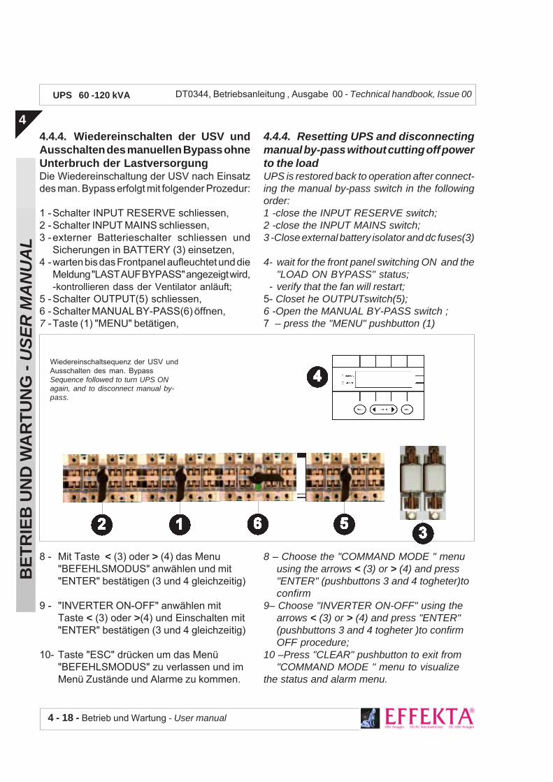
4 - 18 - Betrieb und Wartung - User manual
BE
TR
IEB
UN
D W
AR
TU
NG
- U
SE
R M
AN
UA
L
4
DT0344, Betriebsanleitung , Ausgabe 00 - Technical handbook, Issue 00UPS 60 -120 kVA
4.4.4. Resetting UPS and disconnectingmanual by-pass without cutting off powerto the loadUPS is restored back to operation after connect-ing the manual by-pass switch in the followingorder:1 -close the INPUT RESERVE switch;2 -close the INPUT MAINS switch;3 -Close external battery isolator and dc fuses(3)
4- wait for the front panel switching ON and the"LOAD ON BYPASS" status;
- verify that the fan will restart;5- Closet he OUTPUTswitch(5);6 -Open the MANUAL BY-PASS switch ;7 – press the "MENU" pushbutton (1)
8 – Choose the "COMMAND MODE " menuusing the arrows < (3) or > (4) and press"ENTER" (pushbuttons 3 and 4 togheter)toconfirm
9– Choose "INVERTER ON-OFF" using thearrows < (3) or > (4) and press "ENTER"(pushbuttons 3 and 4 togheter )to confirmOFF procedure;
10 –Press "CLEAR" pushbutton to exit from"COMMAND MODE " menu to visualize
the status and alarm menu.
4.4.4. Wiedereinschalten der USV undAusschalten des manuellen Bypass ohneUnterbruch der LastversorgungDie Wiedereinschaltung der USV nach Einsatzdes man. Bypass erfolgt mit folgender Prozedur:
1 -Schalter INPUT RESERVE schliessen,2 -Schalter INPUT MAINS schliessen,3 -externer Batterieschalter schliessen und
Sicherungen in BATTERY (3) einsetzen,4 -warten bis das Frontpanel aufleuchtet und die
Meldung "LAST AUF BYPASS" angezeigt wird,-kontrollieren dass der Ventilator anläuft;
5 -Schalter OUTPUT(5) schliessen,6 -Schalter MANUAL BY-PASS(6) öffnen,7 -Taste (1) "MENU" betätigen,
8 - Mit Taste < (3) oder > (4) das Menu"BEFEHLSMODUS" anwählen und mit"ENTER" bestätigen (3 und 4 gleichzeitig)
9 - "INVERTER ON-OFF" anwählen mitTaste < (3) oder >(4) und Einschalten mit"ENTER" bestätigen (3 und 4 gleichzeitig)
10- Taste "ESC" drücken um das Menü"BEFEHLSMODUS" zu verlassen und imMenü Zustände und Alarme zu kommen.
Wiedereinschaltsequenz der USV undAusschalten des man. BypassSequence followed to turn UPS ONagain, and to disconnect manual by-pass.

Betrieb und Wartung - User manual 4 - 19
BE
TR
IEB
UN
D W
AR
TU
NG
- U
SE
R M
AN
UA
L
4
DT0344, Betriebsanleitung , Ausgabe 00 - Technical handbook, Issue 00UPS 60 -120 kVA
Einschaltsequenz des Man.Bypass beiAusfall der USVSequence to follow to connect themanual by-pass switch should UPS fail
Wait for 20 seconds and check that the changingstatus from "LOAD ON BYPASS" to "LOAD ONINVERTER". The load is once again powered from UPS.Place the mechanical lock, and eventually thepad-lock too, back onto the MANUAL BY-PASSswitch.
4.4.5. Manual by-pass connection follow-ing UPS failure
When having to exclude the faulty UPS, activatethe manual by-pass switch in the following order:
1 - be sure on the status of alarms "INVERTEROFF", "LOAD ON BYPASS";
2 - remove the mechanical lock (and eventuallythe pad -lock too) blocking the MANUAL BY-PASS switch and lift the lever of MANUALBY-PASS and check the ALARM "MANUALBYPASS ON";
3 - open the OUTPUT switch;4 - open the external battery isolator ;5 - open the INPUT RESERVE switch;6 - open the INPUT MAINS switch.
Should it be necessary to cut-off UPS from theplant (e.g., for repair reasons) the load will conti-nue to be powered only if provided with an externalBy-pass.
20 sec warten und kontrollieren dass dieBetriebszustandsanzeige von "LAST AUFBYPASS" zu "LAST AUF INVERTER" wechselt.Die Last wird nun wieder von der USV versorgt.Die Blockierung und evtl. Hängeschloss desSchalters MANUAL BY-PASS wieder anbringen.
4.4.5. Einschalten des man. Bypass beiAusfall der USV
Wenn die USV wegen Ausfall freigeschaltetwerden soll, schalten Sie den man. Bypass wiefolgt ein:1 - kontrollieren Sie dass die Alarmmeldungen
"INVERTER OFF", "LAST AUF BYPASS"vorhanden sind,
2 -mech. Blockierung (und evtl. Hängeschloss)des Schalters MANUAL BY-PASS entfernen,Schalter MANUAL BY-PASS schliessen undkontrollieren dass die Alarmmeldung "MANUALBYPASS ON" erfolgt,
3 -Schalter OUTPUT öffnen,4 -externer Batterieschalter öffnen,5 -Schalter INPUT RESERVE öffnen,6 -Schalter INPUT MAINS öffnen.
Sollte es notwendig sein die USV von derInstallation abzukoppeln (z.B. für Reparatur),kann die Lastversorgung nur mit einem externenBypass erfolgen und aufrecht erhalten werden.

4 - 20 - Betrieb und Wartung - User manual
BE
TR
IEB
UN
D W
AR
TU
NG
- U
SE
R M
AN
UA
L
4
DT0344, Betriebsanleitung , Ausgabe 00 - Technical handbook, Issue 00UPS 60 -120 kVA
4.5. EINSATZ MIT DEM PCWenn mit einem PC (oder einem PC-Netzwerk)verbunden, kann die USV unter Windows NTverwaltet werden. Der Einsatz der Programm-Software “UPS Management” (optional)ermöglicht automatisches Abschalten von Lokal-PC und Netzwerk-PC, Überwachung der USV-Hauptfunktionen, SNMP Protokoll ... usw.Eine vollständige Funktionsbeschreibung undBetriebsanleitung ist im Software-Paket “UPSManagement” enthalten.
4.5. USE WITH THE PCIf connected to a Personal Computer (or a net-work of PCs) UPS can be managed through theWindows NT application. Management throughthe “UPS Management” software (optional) al-lows to automatically switch off the network’slocal and remote PC, to monitor the main func-tions of UPS , the SNMP protocol, etc.. A fulldescription of the functions and modality of useis given in the “UPS Management” software.
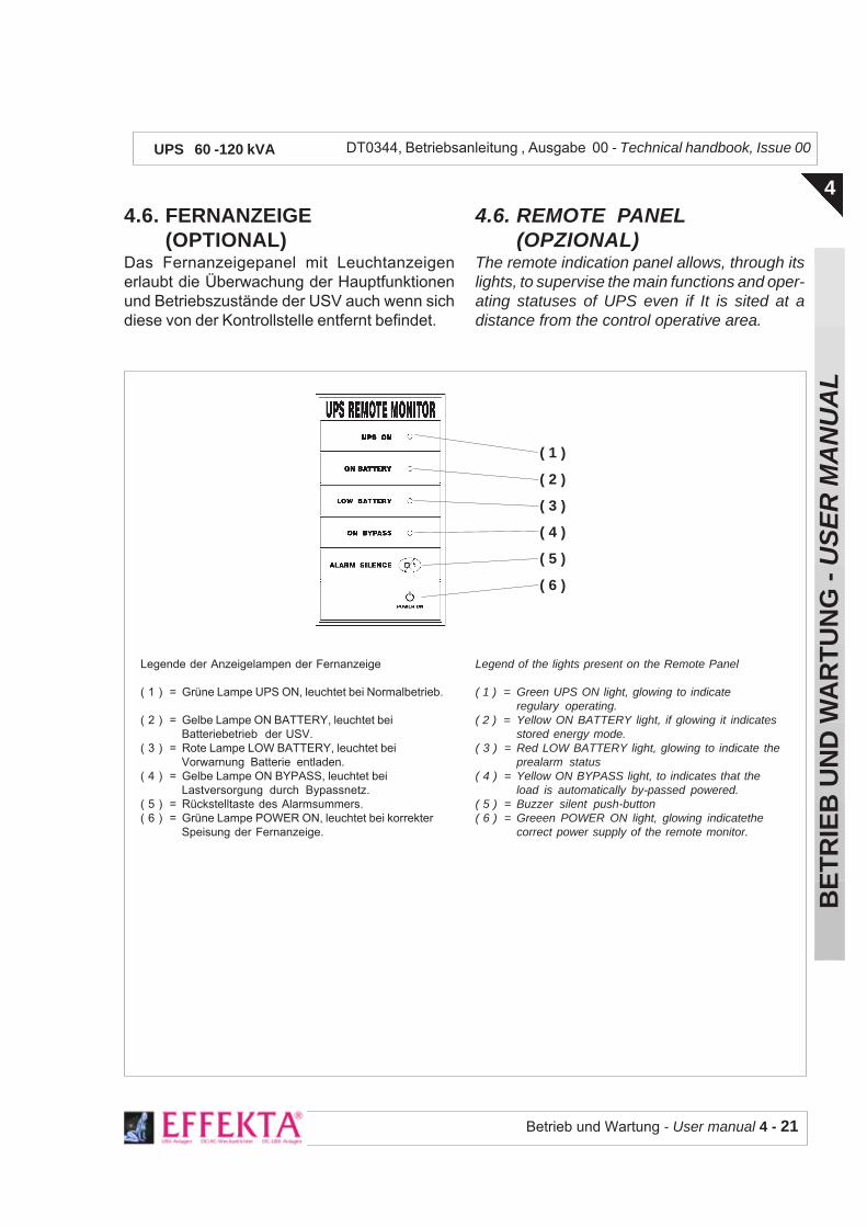
Betrieb und Wartung - User manual 4 - 21
BE
TR
IEB
UN
D W
AR
TU
NG
- U
SE
R M
AN
UA
L
4
DT0344, Betriebsanleitung , Ausgabe 00 - Technical handbook, Issue 00UPS 60 -120 kVA
Legende der Anzeigelampen der Fernanzeige
( 1 ) = Grüne Lampe UPS ON, leuchtet bei Normalbetrieb.
( 2 ) = Gelbe Lampe ON BATTERY, leuchtet beiBatteriebetrieb der USV.
( 3 ) = Rote Lampe LOW BATTERY, leuchtet beiVorwarnung Batterie entladen.
( 4 ) = Gelbe Lampe ON BYPASS, leuchtet beiLastversorgung durch Bypassnetz.
( 5 ) = Rückstelltaste des Alarmsummers.( 6 ) = Grüne Lampe POWER ON, leuchtet bei korrekter
Speisung der Fernanzeige.
Legend of the lights present on the Remote Panel
( 1 ) = Green UPS ON light, glowing to indicateregulary operating.
( 2 ) = Yellow ON BATTERY light, if glowing it indicatesstored energy mode.
( 3 ) = Red LOW BATTERY light, glowing to indicate theprealarm status
( 4 ) = Yellow ON BYPASS light, to indicates that theload is automatically by-passed powered.
( 5 ) = Buzzer silent push-button( 6 ) = Greeen POWER ON light, glowing indicatethe
correct power supply of the remote monitor.
4.6. FERNANZEIGE(OPTIONAL)
Das Fernanzeigepanel mit Leuchtanzeigenerlaubt die Überwachung der Hauptfunktionenund Betriebszustände der USV auch wenn sichdiese von der Kontrollstelle entfernt befindet.
( 1 )
( 2 )
( 3 )
( 4 )
( 5 )
( 6 )
4.6. REMOTE PANEL(OPZIONAL)
The remote indication panel allows, through itslights, to supervise the main functions and oper-ating statuses of UPS even if It is sited at adistance from the control operative area.
4 - 22 - Betrieb und Wartung - User manual
BE
TR
IEB
UN
D W
AR
TU
NG
- U
SE
R M
AN
UA
L
4
DT0344, Betriebsanleitung , Ausgabe 00 - Technical handbook, Issue 00UPS 60 -120 kVA
4.7. ORDENTLICHE WARTUNG
ACHTUNG: Die im Folgenden beschriebenenTests können in, durch die USV versorgten, PCDatenverluste verursachen. Wir empfehlen fürdiese Tests Sicherheitsmassnahmen zu treffen,z.B. durch verwenden nicht-kritischer Lastenoder durch vermeidung von Handlungen dieDatenverluste verursachen könnten.
4.7.1. Funktionsprüfung der USV
Einmal monatlich die Netzversorgung der USVunterbrechen (Schalter INPUT MAINS öffnen)und prüfen dass die Last weiterhin regulär durchdie USV versorgt wird:- Schalter INPUT MAINS öffnen: es müss nun
folgende Meldelampe aufleuchten:- rote Lampe (6) Sammelalarm sowie Alarm-
Summer, mit Taste (2) quittierbar.
4.7.2. Batterieladung
Die Wiederaufladung der Batterie erfolgtautomatisch bei vorhandenem Netz undeingeschalteter USV. Bei entladener Batterieinfolge besonderer Umstände wie z.B. einlängerer Netzausfall, empfehlen wir dieWiederaufladung während der toten Zeiten undbei ausgeschalteter Last (z.B. nachts)durchzuführen. Nach etwa 10-12 Stunden Ladungwird 80% der Nennkapazität erreicht.
4.7.3. Regelmässige Prüfung desReservenetzes
Einmal monatlich die Umschaltung auf demReservenetz durchführen und prüfen dass dieLast weiterhin versorgt wird.Das Vorgehen entspricht der Prozedur wie inKap. 3.1.6. beschrieben.Wenn keine weiteren Ereignisse eintreten,schaltet die USV nach 20 sec wieder nachNormalbetrieb zurück.
4.7. ROUTINE MAINTENANCE
WARNING: The tests described below couldcause loss of data on the UPS powered PCs. Itis suggested to carry out the tests taking secu-rity measures e.g., utilizing uncritical loads oravoiding operations that could cause loss of dataon the system.
4.7.1. Check on UPS intervention
Carry out this test on a monthly basis: cut UPSoff from the input mains (by opening the INPUTswitch) and check that the load is still beingregularly powered from UPS only:- open the INPUT switch, the following lights will
glow:- red general alarm light (6) with quenchable
buzzer alarmPress button (2) to quench the alarm.
4.7.2. Battery recharge
The batteries are automatically recharged throughthe mains voltage and while keeping UPSswitched ON. If the battery is flat due to abnormalconditions i.e., mains cut-off for a long period, itis suggested to recharge the battery during deadworking hours (e.g., evening closing time) andwith the loads switched off.80% of the maximum charge level is reachedafter approx. 10-12 recharging hours.
4.7.3. Routine operating check on thereserve line
This test is carried out on a monthly basis:transfer the load on automatic bypass and checkthat the load is being powered.The operation should follow the procedure de-scribed in paragraph 3.1.6.If no other events arise, UPS will automaticallyrevert to regular operation after 20 seconds.

Betrieb und Wartung - User manual 4 - 23
BE
TR
IEB
UN
D W
AR
TU
NG
- U
SE
R M
AN
UA
L
4
DT0344, Betriebsanleitung , Ausgabe 00 - Technical handbook, Issue 00UPS 60 -120 kVA
4.7.4. Reinigung von Gehäuse,Frontplatte und des Luftfilters
Mit einem Tuch Gehäuse und Frontseiteabstauben; für die Reinigung des Luftfiltersverwenden Sie Pinsel und Staubsauger.ACHTUNGVerwenden Sie keinen Schwamm oder mitWasser oder anderen Flüssigkeiten getränkteTücher, weder für das Gehäuse der USV nochsonstwie in der Nähe davon.
4.8. REGELMÄSSIGE WARTUNGZur Gewährung eines dauernden und effizientenSchutzes der Last empfehlen wir eineregelmässige Wartung der USV einzuplanen.Diese Wartung sollte durch autorisiertestechnisches Personal durchgeführt werden; eswerden dadurch falsches Vorgehen undFehlhandlungen die die korrekte Funktion derUSV beeinflussen und somit Schadenverursachen könnten, vermieden.
4.7.4. Cabinet, Front panel and ventila-tion grid cleaning
Use a duster to clean the cabinet and the frontpanel. To clean the ventilation grid instead, usea brush and a vacuum cleaner.WARNINGDo not use sponges or cloth moistened withwater or other liquids neither on the UPS’s cabi-net nor on surfaces near it.
4.8. PERIODIC MAINTENANCEIt is suggest a periodic maintenance ( to do onplanned expiries) on the UPS to guarantee aconstant and efficent protection of the load.To avoid wrong operations and faults it is betterthat technical personnel or electricians authorized will do the maintenance.

4 - 24 - Betrieb und Wartung - User manual
BE
TR
IEB
UN
D W
AR
TU
NG
- U
SE
R M
AN
UA
L
4
DT0344, Betriebsanleitung , Ausgabe 00 - Technical handbook, Issue 00UPS 60 -120 kVA
ZUSTAND
INVERTEREINGESCHALTET
NETZZULEITUNG OK
ZULEITUNGRESERVENETZ OK
SYNCHRONLAUF OK
BATTERIESPANNUNG OK
LAST AUF INVERTER
LAST AUFRESERVELEITUNG
BEDEUTUNG
Der Inverter ist eingeschaltetund funktioniert normal
Die Haupt-Versorgungs-spannung ist vorhanden undinnerhalb der Toleranzen
Die Spannung der Bypass-Versorgung (Reserveleitung)ist vorhanden und innerhalbder Toleranzen
Gibt an dass die Spannungenvon Inverter und Reservenetzsynchron und in Phase sind
Die Batteriespannung istinnerhalb der Toleranzen
Die Last wirdunterbrechungsfrei durch denInverter versorgt
Die Last wird, nichtunterbrechungsfrei, durch dasReservenetz versorgt.Dieser Zustand kannvorübergehend sein (20 sec),wenn keine weitereAlarmmeldung vorhanden ist.
4.9 BETRIEBSZUSTÄNDE DER USV (Normalbetrieb)
Betrieb und Wartung - User manual 4 - 25
BE
TR
IEB
UN
D W
AR
TU
NG
- U
SE
R M
AN
UA
L
4
DT0344, Betriebsanleitung , Ausgabe 00 - Technical handbook, Issue 00UPS 60 -120 kVA
STATUS
INVERTER OPERATING
MAINS WITHIN LIMITS
BYPASS LINE WITHIN LIMITS
I N V E R T E R - B Y P A S SSINCRONIZED
BATTERY VOLTAGE WITHINLIMITS
LOAD ON INVERTER
LOAD ON BYPASS
INTERPRETATION
The inverter is turned on and itis normally running
The input mains is present andthe voltage is in specified range
The input bypass line is presentand the voltage is in specifiedrange
Indication of regular syncronismstate between inverter andbypass
The battery voltage is inspecified limits
Load is supplied from theInverter
Load is supplied from theBypass line. This can be atemporarycondition for 20sec ifno alarm present.
4.9 UPS STATUS (normal mode)

4 - 26 - Betrieb und Wartung - User manual
BE
TR
IEB
UN
D W
AR
TU
NG
- U
SE
R M
AN
UA
L
4
DT0344, Betriebsanleitung , Ausgabe 00 - Technical handbook, Issue 00UPS 60 -120 kVA
ALLARMMELDUNG
INVERTER OFF
ÜBERLAST INVERTER
BATTERIE NICHTEINGESCHALTET
BATTERIE ENTLADEN
BATTERIE BALD ENTLADEN
FEHLER BATTERIELADUNG
FEHLERSTATISCHER SCHALTER
STATISCHER SCHALTERBLOCKIERT
BYPASS-NETZ NICHT OK
NETZZULEITUNG NICHT OK
MAN. BYPASSEINGESCHALTET
NOT-ABSCHALTUNG
MÖGLICHE URSACHE
Erst-EinschaltungDauer-Überlast oderKurzschluss am Ausgang
Dauer-Überlast oderKurzschluss am Ausgang
Batterie-Trennschalter offenoder Batterie nicht verbundenBatterietest misslungen
Längerer Netzausfall
Baldiges Ende der Batterie-Au-tonomie
Möglicher Fehler derBlockierung des statischenSchalters
Hohe Stromspitzen der Last
Spannung Bypassnetzausserhalb der eingestelltenToleranzenSpannung Netzzuleitungausserhalb der eingestelltenToleranzen
Wartung der USV
NOT-AUS-Taste wurde betätigt
LÖSUNGEN
Inverter einschaltenAn USV angeschlossene Lastüberprüfen
An USV angeschlossene Lastüberprüfen
Trennschalter schliessen oderBatterie verbindenBatterie überprüfen
Angeschlossene Lastabschalten
Kundendienst für Batterie-Ersatz kontaktieren
Bypass-SCR überprüfen
Angschlossene Last überprüfenund Warnmeldung rückstellen
Spannung Bypassnetzüberprüfen
Spannung Netzzuleitungüberprüfen
Ursache kontrollieren. USVvollständig ausschalten. Für dieWiedereinschaltung Prozedurgemäss Kap. 3.1.1 derBetriebsanleitung befolgen.
4.10. FEHLERSUCHE

Betrieb und Wartung - User manual 4 - 27
BE
TR
IEB
UN
D W
AR
TU
NG
- U
SE
R M
AN
UA
L
4
DT0344, Betriebsanleitung , Ausgabe 00 - Technical handbook, Issue 00UPS 60 -120 kVA
ALARM
INVERTER OFF
INVERTER OVERLOAD
BATTERY NOT CONNECTED
BATTERY END OF DISCARGING
BATTERY PREALARM
BATTERY CHARGER FAILURE
BYPASS SWITCH FAILURE
STATIC SWITCH LOCKED
BYPASS LINE OUT OF LIMITS
MAINS OUT OF LIMITS
MANUAL BYPASS ON
EMERGENCY POWER OFF
CAUSE
Initial start-upPermanent output overload oroutput short circuitPermanent output overload oroutput short circuit
Battery breaker off or batterynot connectedBattery test fail
Mians missing for long time
Battery almost flat, next toshutdown
One or more phase in the outputare missing
High output inrush current
Bypass line voltage out of thespecified limits
Mains line voltage out of thespecified limits
UPS on maintenance
EPO command activated
ACTION
Start the InverterCheck the loads connected tothe UPSCheck the loads connected tothe UPS
Switch on the batery fuses orconnect the batteryCheck the battery elements
Make shutdown to theconnected loads
Call sevice office to replace thebattery charger
Check Bypass SCR
Check the loads connected andreset to normal condition
Check the bypass line voltage
Check the mains line voltage
Investigate on cause. Switchoff completely the UPS. Torestart follow the procedure onparagraph 3.1.1 on user manual
4.10. TROUBLESHOOTING