Embed Size (px)
Citation preview

The INL is a U.S. Department of Energy National Laboratory operated by Battelle Energy Alliance
INL/EXT-16-40793 Revision 0
Uranium Casting Materials Development: HfN Testing Summary
January 2017
DISCLAIMER Neither the U.S. Government nor any agency thereof, nor any of their employees, makes any warranty, expressed or implied, or assumes any legal liability or responsibility for the accuracy, completeness, or usefulness, of any information, apparatus, product, or process disclosed, or represents that its use would not infringe privately owned rights. References herein to any specific commercial product, process, or service by trade name, trade mark, manufacturer, or otherwise, does not necessarily constitute or imply its endorsement, recommendation, or favoring by the U.S. Government or any agency thereof. The views and opinions of authors expressed herein do not necessarily state or reflect those of the U.S. Government or any agency thereof. Being provided this document, directly or indirectly, shall not be construed to constitute a governmental export license or authorization.
GENERATED INFORMATION – UNLIMITED RIGHTS This document contains, at least in part, Generated Information – Unlimited Rights arising under 13-CR-13 between TerraPower, LLC, and Battelle Energy Alliance, LLC.
Uranium Casting Materials Development: HfN Testing Summary
Randall Fielding
January 2017
Idaho National Laboratory Nuclear Science and Technology
Idaho Falls, Idaho 83415
http://www.inl.gov
Prepared for TerraPower, LLC
Under CRADA 13CR13 Under DOE Idaho Operations Office
Contract DE-AC07-05ID14517


iv
ABSTRACT
A total of four dip tests were performed on TerraPower provided HfN coated niobium coupons. However, in the first two tests, excessive oxidation of the charges materials led to inadequate contact between the HfN coated specimens and the molten alloy. The final two tests used a much higher ramp rate, which provided less time for oxidation of the melt. In both of these tests, the dipped specimens appeared fully intact and coated with metal alloy. The alloy could not be easily removed, suggesting either a mechanical interlocking or a chemical bonding. Due to shifting programmatic priorities, metallographic examination of the samples was not performed.

v

vi
CONTENTS
ABSTRACT ................................................................................................................................................. iv
ACRONYMS ............................................................................................................................................. viii
1. INTRODUCTION AND PURPOSE .................................................................................................. 1
2. EXPERIMENT ................................................................................................................................... 1
3. RESULTS ........................................................................................................................................... 2
4. CONCLUSIONS ................................................................................................................................ 8
FIGURES Figure 1. BCS-II shown in the fume hood (left) and internal cut-away schematic showing basic
internal components (right)........................................................................................................... 2
Figure 2. Dipping fixtures used for the first two dip tests. ........................................................................... 2
Figure 3. Result of the first dip test HfN-1 (left) and HfN-2 (right). ............................................................ 3
Figure 4. Heating profile of the first dip test. ................................................................................................ 3
Figure 5. Resulting sample from the second dip test. Notice the coating degradation along the right side of the figure. ................................................................................................................. 4
Figure 6. Heating profile showing rapid ramp rate to decrease time alloyed for oxidation. ......................... 5
Figure 7. Resulting sample from the third dip test (left) and the third dip test heel showing no undissolved zirconium or oxide shells (right). ............................................................................. 5
Figure 8. Thermal profile resulting from the fourth and final dip test, which used two samples dipped simultaneously. ................................................................................................................. 6
Figure 9. Resulting discs from the fourth dip test. ........................................................................................ 6
Figure 10. Resulting heel from the fourth dip test. ....................................................................................... 7
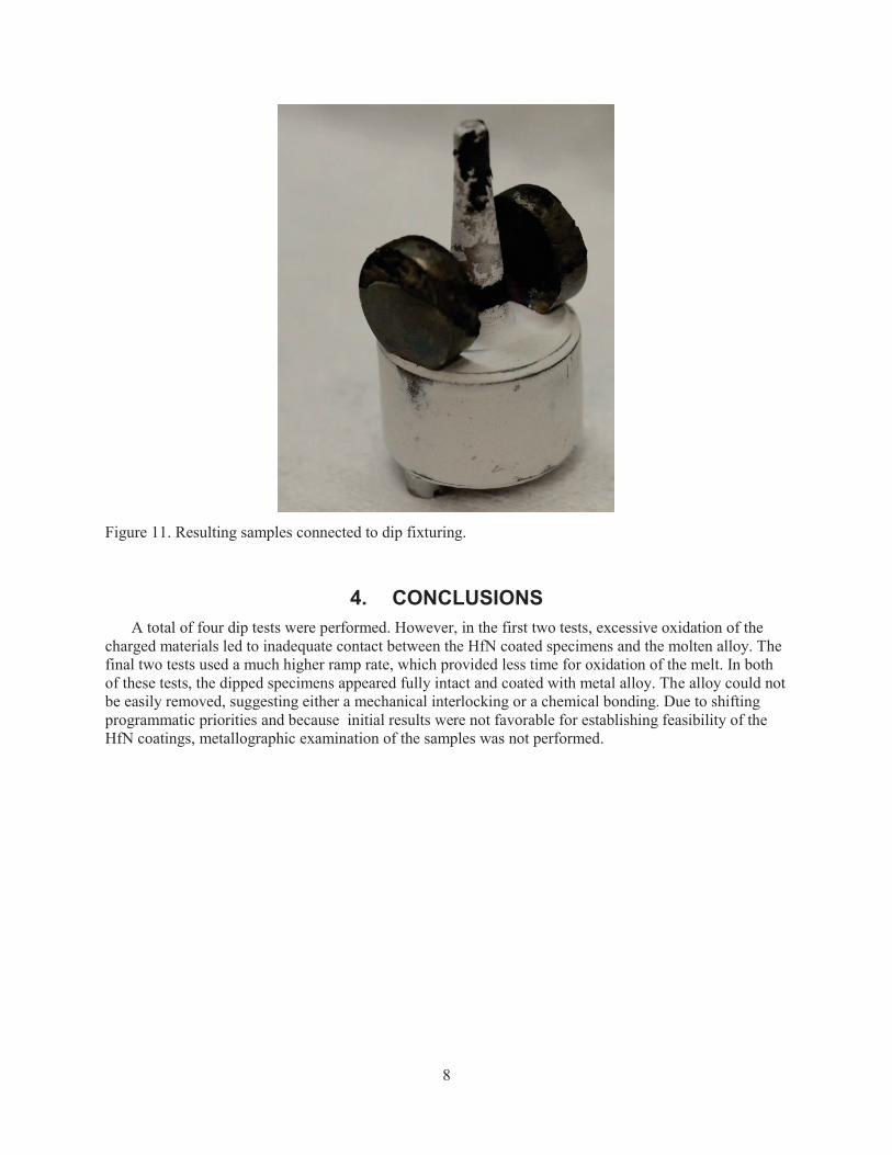
Figure 11. Resulting samples connected to dip fixturing. ............................................................................. 8

vii

viii
ACRONYMS BCS-II Benchtop Casting System-II
HfN hafnium nitride
INL Idaho National Laboratory

1
Uranium Casting Materials Development: HfN Testing Summary
1. INTRODUCTION AND PURPOSE During the fuel fabrication process, extrusion billets will be cast using permanent molds. Current
practice at the Idaho National Laboratory (INL) is to fabricate permanent molds for uranium and uranium alloy casting from graphite material. Graphite molds have several advantages: graphite is readily commercially available in a number of grades and forms, it is relatively low cost, it can be heated in an inert or vacuum environment to the uranium and uranium alloy casting temperatures, and it is generally easy to machine. The main disadvantage to using graphite as a mold material is that graphite is very reactive with uranium and most commonly used fuel alloying agents at the high casting temperatures that can reach up to 1450 C for the alloys of interest. Graphite reactivity may lead to excessive carbon contamination of the cast product or may chemically bond with the cast product forming a metal carbide phase. Reaction with the melt can be somewhat limited by keeping mold temperatures low, although some casting require a heated mold to produce acceptable final products.
The other commonly used mitigation strategy is to apply a chemically inert coating on the surface of the graphite to minimize interaction with the molten uranium to acceptable levels. Several coatings have been used with Y2O3 and ZrO2 being the most commonly used at the INL. Coatings can be applied in a number of ways. Slurry coating, or painting, as either a brush or aerosol are simple and efficient coating methods. However, coatings applied in this manner are generally single use, requiring cleaning and reapplication between each casting run, and may actually stick to or contaminate the surface of the casting product. As an alternative to single use coatings, and possible graphite contamination, TerraPower has suggested using a refractory metal mold coated with a permanent coating. In order to investigate the feasibility of a coated refractory metal mold, several hafnium nitride (HfN) coated niobium samples were provided to the INL by TerraPower early calendar year 2014 for testing. The samples were tested by the INL via dip testing in a molten uranium alloy pool to simulate the conditions the material would experience when applied as a mold coating. After exposure in the molten fuel alloy, the test coupons were examined to determine the integrity of the coating and the amount of chemical interaction.
2. EXPERIMENT Dip testing was carried out using the Benchtop Casting System-II (BCS-II) vacuum induction melting
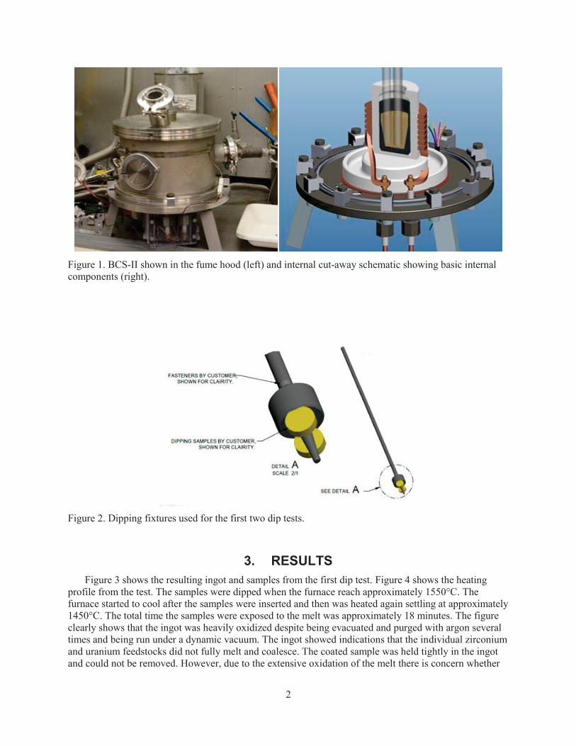
and casting furnace. The BCS-II is an induction heated furnace which utilizes Y2O3 coated graphite crucibles. Figure 1 shows the BCS-II in the fume hood and cut-away schematic showing the basic internal components. Although, the furnace was slightly reconfigured to perform the dip testing. Uranium and zirconium or pre-alloyed feedstocks were loaded into the crucible at a ratio to provide a final alloy having 10% zirconium, by mass. Uranium rods 0.5” diameter cut to various lengths, SPM# 182-60-1174, were used and the zirconium feedstock was excess zirconium obtained for EBR-II fuel fabrication in the form of thick machine turnings. A graphite dipping fixture was designed to hold the coated samples. A sketch of the fixture used for the first and fourth test is shown in Figure 2. The fixture was machined from graphite, with a threaded connection to a graphite rod that was fed out of the furnace for manual insertion into or out of the melt. Coated coupons were fastened to the fixture through refractory metal screws, also shown in the sketch. The center pillar shown on the fixture was included to ensure a consistent depth of dip from test to test. The second and third tests utilized a single graphite rod with a threaded connection that connected to the coated coupon without depth control. For each dip test the furnace was heated to 1450°C and the sample dipped into the molten melt for 1 minute, then the furnace was allowed to cool. Following cooling the samples and melted charge were examined.
2
Figure 1. BCS-II shown in the fume hood (left) and internal cut-away schematic showing basic internal components (right).
Figure 2. Dipping fixtures used for the first two dip tests.
3. RESULTS Figure 3 shows the resulting ingot and samples from the first dip test. Figure 4 shows the heating
profile from the test. The samples were dipped when the furnace reach approximately 1550°C. The furnace started to cool after the samples were inserted and then was heated again settling at approximately 1450°C. The total time the samples were exposed to the melt was approximately 18 minutes. The figure clearly shows that the ingot was heavily oxidized despite being evacuated and purged with argon several times and being run under a dynamic vacuum. The ingot showed indications that the individual zirconium and uranium feedstocks did not fully melt and coalesce. The coated sample was held tightly in the ingot and could not be removed. However, due to the extensive oxidation of the melt there is concern whether

3
the coupon was in actual contact with the molten material or rather the oxide shell. Some damage can be seen on sample HfN-1, although the damage is above the melt and is most likely mechanical damage caused during subsequent handling and efforts to remove from the ingot. HfN-2 shows less mechanical damage; however, an interaction layer can be seen just above the fuel line. Further microstructural investigation of the samples was not performed because the melt did not fully coalesce.
Figure 3. Result of the first dip test HfN-1 (left) and HfN-2 (right).
Figure 4. Heating profile of the first dip test.
Based on this test, the next test used a pre-alloyed U-10Zr button as feedstock. The heat cycle was similar; however, to allow more time for any off gas to be removed from the system by the vacuum the heat up rate was much slower. The charge was brought up to 1450°C and the test coupon dipped. In order to conserve samples the dipping fixture was changed to a single sample. The pre-alloyed button used was fabricated using the arc melting process, which results in a well-mixed alloy. The sample was dipped and removed from the melt and exampled. The resulting sample is shown in Figure 5. From the appearance of the sample, it appears that either the sample was not inserted into the crucible deep enough to make
0200400600800
1000120014001600
00:00 03:00 06:00 09:00 12:00 15:00 18:00 21:00 24:00
Tem
pera
ture
(C)
Run Time (mm:ss)
2-26-2014 Dip Test

4
contact with the molten pool or because of the heavy oxide layer which was present on the melt full contact was not achieved. However, although there was no obvious melt/coupon interaction, the coating does show signs of degradation from either oxidation or the thermal cycle or a combination of both.
Figure 5. Resulting sample from the second dip test. Notice the coating degradation along the right side of the figure.
Due to the excessive oxidation seen in the previous two tests, the third test used a much faster heating
rate in order to achieve the 1450°C melt temperature with as little time to oxidize as possible. The heating profile is shown in Figure 6. In this test, the entire sample was immersed in the melt. The resulting disc and heel are shown in Figure 7. The resulting heel appears to be fully melted and consolidated with no remaining uranium or zirconium shells visible. The sample also appears to have no visible damage due to exposure to the melt; however, the fuel material adhered tightly to the sample and could not be removed.

5
Figure 7. Resulting sample from the third dip test (left) and the third dip test heel showing no undissolved zirconium or oxide shells (right).
Because of the success of the third dip test a final test was performed with the original fixturing which contained two HfN coated specimens. This final dip test again used a high heating rate in order to reduce the amount of time for additional oxidation. The thermal profile is shown in Figure 8. Once 1450°C was reach the temperature was held for approximately 5 minutes before the samples were dipped into the melt, exposed for 1 minute and withdrawn. The test went well with approximately half of the discs being coated with the fuel alloy. The resulting test samples, resulting heel, and dipping fixture are shown in Figures 9–11. Visual examination of the coated samples showed the sample to be fully intact and partially covered with the alloy, with some signs of oxidation as well. The adhering material appeared firmly attached to the specimens and could not be removed through scraping. The samples were sectioned through the center axis and mounted for metallographic inspection; however, due to programmatic priorities, the inspections did not take place.
0100200300400500600700800900
100011001200130014001500
Tem
pera
ture
(C)
Run Time
3-25-2014 Dip Test
Figure 6. Heating profile showing rapid ramp rate to decrease time alloyed for oxidation.

6
Figure 8. Thermal profile resulting from the fourth and final dip test, which used two samples dipped simultaneously.
Figure 9. Resulting discs from the fourth dip test.
0
200
400
600
800
1000
1200
1400
1600
00:00 01:00 02:00 03:00 04:00 05:00 06:00 07:00 08:00 09:00 10:00 11:00
Tem
pera
ture
(C)
Run Tim (mm:ss)
3-27-2014 Dip Test

7
Figure 10. Resulting heel from the fourth dip test.
8
Figure 11. Resulting samples connected to dip fixturing.
4. CONCLUSIONS A total of four dip tests were performed. However, in the first two tests, excessive oxidation of the
charged materials led to inadequate contact between the HfN coated specimens and the molten alloy. The final two tests used a much higher ramp rate, which provided less time for oxidation of the melt. In both of these tests, the dipped specimens appeared fully intact and coated with metal alloy. The alloy could not be easily removed, suggesting either a mechanical interlocking or a chemical bonding. Due to shifting programmatic priorities and because initial results were not favorable for establishing feasibility of the HfN coatings, metallographic examination of the samples was not performed.


![Two-way standmount loudspeaker Made by: Sonus faber SpA ... · Aida [HFN Apr ’12], Lilium [HFN Jun ’15] and particularly ‘Il Cremonese’ [HFN Aug ’16], and the revamping](https://img.pdfslide.net/doc/110x75/5f60376dbd71ed04124f3d4f/two-way-standmount-loudspeaker-made-by-sonus-faber-spa-aida-hfn-apr-a12.jpg)