Embed Size (px)
Citation preview

ICMAR 2014
1
URANS AND LES OF A FLOW OVER A CYLINDER AT Re = 3900
E. Palkin1,2, R. Mullyadzhanov1,2, K. Hanjalic2,3 1 Kytateladze Institute of Thermophysics SB RAS, 630090, Novosibirsk, Russia
2 Novosibirsk State University, 630090, Novosibirsk, Russia 3 Delft University of Technology, 2600 AA, Delft, The Netherlands
Introduction The flow over a cylinder has been the subject of various experimental and numerical studies. De-
spite a simple formulation of the problem of a uniform flow of the velocity U over a rigid cylinder of the diameter D, there are many different regimes [1] depending on one dimensionless parameter, which is the Reynolds number Re = UD/ν, where ν is the viscosity of the fluid. This flow offer inherently com-plex regimes to verify obtained characteristics with computational fluid dynamics (CFD) models.
At Reynolds number below 40 the flow is laminar and steady with contra-rotating vortices at-tached to the cylinder. In the gap between 40 and 180 the flow is still laminar but Karman's vortex street phenomenon appears appearing. Next, in the interval Re⊂[180; 400] the instabilities cause the flow to make a transition from two-dimensional to three-dimensional flow. In Re⊂[2·105
; 5·105] gap transition to turbulence occurs in shear layer and the separation commences to downstream side of cylinder, in region with higher Re the turbulence appears in the yet before boundary separation and consequently the wake is entirely turbulent.
This paper presents numerical studies of the flow over the cylinder at Reynolds number of 3900, so called irregular or subcritical range (in the subcritical regime, i.e. the boundary layer be-fore the separation is laminar). Therefore the flow exhibits laminar separation followed by transition to turbulence in shear layer. This paper focuses on revealing implicit reasons of inability to resolve the flow URANS approach.
Numerical studies, utilizing averaged Navier – Stokes equations (RANS) for turbulent model, usually exert unsatisfactorily results within subcritical Reynolds numbers [5, 6, 10] in modelling flow over the circular cylinder. For the CFD test cases in this paper the standard model ζ-f and dy-namic Smagorinsky subgrid models were used for URANS and LES computations correspondingly. The results received from series of grids with different resolution in recirculation zone and trans-verse direction are presented in this work and compared with referenced ones. Node count reached up to 1.44·106 for URANS and 15·106 for LES meshes.
Numerical methodology
1
0
i ji j ji i
j i j j i j
ii
u uU U UU Up
t x x x x x x
Ux
νρ
∂ ∂ ∂∂ ∂∂ ∂+ = − + + − ∂ ∂ ∂ ∂ ∂ ∂ ∂ ∂ = ∂
(1)
RANS equation (1) takes origin in the Navier – Stokes equations. Averaging of oscillating fields in this equation can be obtained by decomposing velocity in carious of ways. Most utilizing the Reynolds decomposition which implies any instant flow characteristic θ (velocity, pressure, temperature etc.) can be decomposed on average �̄ and fluctuating �́ component. In RANS ap-proach averaging over the sufficient time is using what is in agreement only within stationary flows nominally. The averaging can be applied to unstationary flows though if time scale of average flow is much larger the turbulent ones. In case of periodical flows it is convenient to conduct the averag-ing with phase averaging with some characteristic flow period.
E. Palkin, R. Mullyadzhanov, K. Hanjalic, 2014
Section 3: Gas Dynamics of Internal and External Flows
2
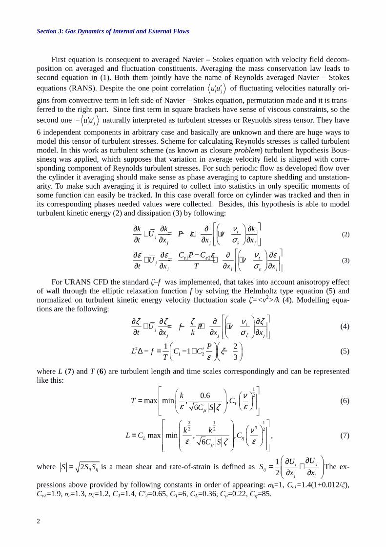
First equation is consequent to averaged Navier – Stokes equation with velocity field decom-position on averaged and fluctuation constituents. Averaging the mass conservation law leads to second equation in (1). Both them jointly have the name of Reynolds averaged Navier – Stokes equations (RANS). Despite the one point correlation i ju u′ ′ of fluctuating velocities naturally ori-
gins from convective term in left side of Navier – Stokes equation, permutation made and it is trans-ferred to the right part. Since first term in square brackets have sense of viscous constraints, so the second one i ju u′ ′− naturally interpreted as turbulent stresses or Reynolds stress tensor. They have
6 independent components in arbitrary case and basically are unknown and there are huge ways to model this tensor of turbulent stresses. Scheme for calculating Reynolds stresses is called turbulent model. In this work as turbulent scheme (as known as closure problem) turbulent hypothesis Bous-sinesq was applied, which supposes that variation in average velocity field is aligned with corre-sponding component of Reynolds turbulent stresses. For such periodic flow as developed flow over the cylinder it averaging should make sense as phase averaging to capture shedding and unstation-arity. To make such averaging it is required to collect into statistics in only specific moments of some function can easily be tracked. In this case overall force on cylinder was tracked and then in its corresponding phases needed values were collected. Besides, this hypothesis is able to model turbulent kinetic energy (2) and dissipation (3) by following:
tj
j j k j
k k kU P
t x x x
νε νσ
∂ ∂ ∂ ∂+ = − + + ∂ ∂ ∂ ∂ (2)
1 2 tj
j j j
C P CU
t x T x xε ε
ε
ε νε ε ενσ
−∂ ∂ ∂ ∂+ = + + ∂ ∂ ∂ ∂ (3)
For URANS CFD the standard ζ–f was implemented, that takes into account anisotropy effect of wall through the elliptic relaxation function f by solving the Helmholtz type equation (5) and normalized on turbulent kinetic energy velocity fluctuation scale ζ=<v 2>/k (4). Modelling equa-tions are the following:
tj
j j j
U f Pt x k x xζ
νζ ζ ζ ζνσ
∂ ∂ ∂ ∂+ = − + + ∂ ∂ ∂ ∂ (4)
21 2
1 21
3
PL f C C
Tζ
ε ′∆ − = − + −
(5)
where L (7) and T (6) are turbulent length and time scales correspondingly and can be represented like this:
1
20.6max min , ,
6T
kT C
C Sµ
νε εζ
=
(6)
3 1 132 2 2
max min , ,6
L
k kL C C
C Sη
µ
νε εζ
=
, (7)
where 2 ij ijS S S= is a mean shear and rate-of-strain is defined as 1
2ji
ijj i
UUS
x x
∂∂= + ∂ ∂ The ex-
pressions above provided by following constants in order of appearing: σk=1, Cε1=1.4(1+0.012/ξ), Cε2=1.9, σε=1.3, σξ=1.2, C1=1.4, C'2=0.65, CT=6, CL=0.36, Cµ=0.22, Cη=85.

ICMAR 2014
3
In LES approach based on filtering original Navier – Stokes equations divides “small” eddies on sub-grid scale level from “large” scales. Thus, filtering operation can be defined to decompose the velocity into sum of two parts of filtered (or resolved) ( , )U x t and residual (or subgrid-scale, SGS) component ( , )u x t′ . Following LES equations (8) are given:
1 1
0
ii jj i j iji ii
j i j j i j
iii
U U UU Up
t x x x x x x
Ux
τν
ρ ρ ∂ ∂ ∂∂ ∂∂ ∂+ = − + + − ∂ ∂ ∂ ∂ ∂ ∂ ∂
∂ = ∂
, (8)
where wall shear stress is need to be modelled. In case of this paper Smagorinsky subgrid-scale model (9) was used:
21
31
2 23ij kk ij t ij s ijS C V S Sτ τ δ ν
− = − = −
(9)
with constant Cs = 0.2.
Computational details Figure 1 shows the computational domain of the size 25D×20D×4D in Cartesian coordinates
for LES and 25Dx10Dx1or2D for URANS. The mesh consists of 15×106 hexahedral cells for LES and about 9×10⁵ for URANS. All the boundary conditions shown are and numbered from “1” to “4”. The cylinder is placed 10D downstream from the inflow plane where a uniform flow (U, 0, 0) is set and that area marked as “2”. The spanwise (in z direction) length of the cylinder is Lz = 4D for LES and Lz = 1D/2D for URANS. Periodic boundary conditions are set at “1”. The slip condition is set at “4”, which suppose normal velocity is zero, while the convective outflow is set at “3”. On the rigid surface of the cylinder the no-slip condition is applied. For URANS and hybrid LES/URANS number of grids was created conditionally marked as 1d_coarse, 2d_coarse, 1d_fine, 2d_fine, 1d_finest, 2d_finest, where “1d” or “2d” mark mean transverse length value to yield out 3D flow. Other marks, bound with refinement, such as “coarse”, “fine”, ”finest”, signify overall grid resolu-tion and primly in recirculation zone. All base grid parameters are shown in Table 1. Various mesh-es provide different computational time consumes for same amount of shedding cycles. It is obvi-ous, that time consumed increases when resolution rising (Fig. 2).
Fig. 1. Computational domain with boundary condi-tions and geometry.
1 – periodic boundary condition, 2 – uniform flow in the inlet, 3 – convectional boundary condition, 4 – slip boundary condition.

Section 3: Gas Dynamics of Internal and External Flows
4
Table 1 . Details of computational meshes used in study*
Cases Nd Nr Na Nz
LES 15823872 80 268 256
1d_coarse 153452 28 160 14
2d_coarse 306904 28 160 28
1d_fine 448868 44 200 24
2d_fine 897736 44 200 48
1d_finest 861366 52 220 32
2d_finest 1722732 52 220 64
Hybrid 2d_fine 897736 44 200 48
* Na denoted number of the radial nodes, Nz is stand for azimuth nodes number, Nr is the number of nodes in well-resolved recirculation zone and Nd is total number of nodes)
The TU Delft unstructured finite-volume computational code T-FlowS was employed on these
meshed which can be applied on unstructured meshes and has second order precision schemes im-
plemented. The convective and diffusion terms in equations (1-4) were discretised by central-difference scheme of second order precision in blending with portion (1.5%) of first order accuracy
upwind scheme to increase the convergence and overall stability in sacrifice to insufficient precision
[6]. Time paces were performed by three-step fully-implicit scheme. The pressure field was calcu-
lated with SIMPLE procedure on found velocities. The LES simulations were advanced through time with a CFL number of approximately 0.5,
timestep was set to 0.005 for that purposes, all URANS simulation were carried out with timestep
equal to 0.05.
Results The overall acting forces of cylinder are important parameters and represented in table 2 with
some corresponding values from literature.
Fig. 2. Close transverse view on computational mesh near the cylinder. left – finest RANS mesh, right – LES mesh.

ICMAR 2014
5
In table 2 presents comparison between computational data and experimental from [5, 8, 9]. It
contains mean drag dС , the mean base pressure coefficient bpC , recirculation zone length Lr/D,
Strouhal number St = f D/U for most CFD cases. The base pressure coefficient is a general indicator
Table 2 . Drag, pressure, recirculation zone length, Strouhal number and separation angle
Cases dС
bpC Lr/D St θ
URANS 2d_fine 1.33 1.6 0.45 0.21 89
Young and Ooi
URANS 3D [5] 1.32 1.42 0.51 0.22 –
Ma et al. DNS Case II [9] 0.84 – 1.59 0.22 –
Lourenco and
Shih PIV [8] 0.99 0.9 1.19 0.22 86
Fig. 3. Streamlines on mean velocity field. From the top: 1 – 2d_coarse URANS, 2 – URANS from [5], 3 – LES from [5], 4 – PIV from [7].

Section 3: Gas Dynamics of Internal and External Flows
6
of whether the pressure in the wake is correct and therefore whether the overall drag is correct.
There you can see RANS predictions are quite poor, besides Strouhal number. The separation angle
of laminar boundary layer is in well agreement with referenced results. Streamlines on mean velocity field in Fig. 3 URANS generally underestimates the recirculation
region, that entail discrepancies in mean velocity and Reynolds stresses profiles. Overall URANS
performance is rough in this task and mesh refinement does not introduce major improvements.
This is in an agreement with URANS simulation obtained from [5] and shown in Fig. 3 as the sec-
ond graph (second URANS graph was obtained from higher resolution mesh). Simulation based on
LES, on contrary, slightly overestimate bubble length beyond experimental values adopted from [7],
as it can be seen comparing the vortex cores. It is hypothesized and outlined in [6] that reasons ori-
gins in not fully laminar flow in impinging flow therefore results in earlier transition to turbulence
and lower recirculation zone length. In all simulations y
+>1was achieved with meshes in near-wall region.
Figure 4 contains averaged over sufficient time mean U and V velocities plots in series of
crossections along the downstream past the cylinder. All following graphs compared with DNS data
from [3], LES and PIV data from [4]. It is certain that URANS deviations from rest of graphs
caused with smaller recirculation zone, in fact, all those chosen cross sections missing the bubble
completely, so only free shear flow (in average) past the bubble is detected by URANS. LES data
conforms mostly with the referenced ones In Fig. 5 there are mean uu and uv Reynold stresses are represented. Convergence between
LES data and referenced one is major, as well as URANS data with one, cited in [5]. But generally
URANS overpredict rest of the data. Reason are systematized in next part. Basic reason for that is following: URANS behaviour lies in method of averaging. As in been
mentioned in the end of introduction, the proper averaging in flows, which excels periodic movement,
requires decomposing velocity in three parts: averaged of sufficient time ( , )U x t without taking into
Fig. 4. Mean U and V velocities in different cross sections downstream.

ICMAR 2014
7
account coherent (periodic) ( , )iU x tϕcomponent and stochastic one (fluctuating) ( , )
i
su x t . There-
fore, after averaging the Navier – Stokes equations with phase-averaging the following expression
can be received:
( )
1i j ji i
j i j j i
s s s si j i j j i i j i j
j
U U UU Up
t x x x x x
U U U U U u U u u ux
νρ
∂ ∂∂ ∂∂ ∂ + = − + + −
∂ ∂ ∂ ∂ ∂ ∂
∂− < > − + < > + < > + < >∂
(10)
where angle brackets < > denotes phase-averaging. It was found out that s sj i i jU u U u< > + < >
is of order of magnitude smaller than s si ju u as well as i j i jU U U U− . Original URANS
equation uses this form, substituting phase-averaging with averaging over sufficient time which is
exactly match with (1):
1i j ji i s si j
j i j j i j
U U UU p Uu u
t x x x x x xν
ρ
∂ ∂∂ ∂ ∂∂ ∂+ == − + + − < > ∂ ∂ ∂ ∂ ∂ ∂ ∂
(11)
Conclusion
There has been demonstrated high divergence between URANS data and LES/DNS one and
this is in a fully agreement with other attempt using basics scheme. There are the several reasons for
that, as it hypothesised. First one is in the meaning of averaging itself, in case flows with exhibit
Fig. 5. Mean uu and uv Reynolds stresses in different cross sections downstream.

Section 3: Gas Dynamics of Internal and External Flows
8
periodical movement averaging should be performed with phase averaging, it will correspond co-herent part of the flow and fluctuating part called stochastic. Therefore, URANS will capture peri-odic movement. Second reason challenged the Boussinesq hypothesis itself: in certain well defined regions past the cylinder there are areas with negative turbulent viscosity or, so called, counter gra-dient transfer. If so, in turbulent kinetic energy and dissipation equations (2), (3) exert negative pro-duction P = νtS
2 , which in straight sense prolongs the recirculation zone: the action of mean ve-locity gradient working on Reynolds stresses side, transferring the kinetic energy to the mean flow by removing it from the turbulent stresses and LES computations confirms this. The other, third one reason constitute that URANS cannot capture vortex shedding instability [11] with Strouhal vortex shedding simultaneously. This instability occurs in separation layer with higher frequency than reg-ular vortex shedding, and, consequently these small vortices result in interference lower frequency shedding; therefore, there is the number of frequencies beside the Strouhal.
REFERENCES
1. Hanjali ć K., Popovac M., Hadžiabdić M. A robust near-wall elliptic relaxation eddy-viscosity turbulence model for CFD // Int. J. Heat Fluid Flow. 2004. Vol. 25, No. 6. P. 1047–1051.
2. Afgan I., Kahil Y., Behhamadouche S., Sagaut P. Large eddy simulation of the flow around single and two side-by-side cylinders at subcritical Reynolds numbers // Phys. Fluids. 2011. Vol. 23. 075101.
3. Lehmkuhl O., Rodrigez I., Borrell R., Oliva A. Low-frequency unsteadiness in the vortex formation region of a circular cylinder // Phys. Fluids. 2013. Vol. 25. 085109.
4. Parnaudeau P., Carlier J., Heitz D., Lamballais E. Experimental and numerical studies of the flow over a circular cylinder at Reynolds number 3900 // Phys. Fluids. 2008. Vol. 20. 085101.
5. Young M. E., Ooi A. Comparative Assessment of LES and URANS for Flow Over a Cylinder at a Reynolds Number of 3900 // 16th Australasian Fluid Mechanics Conference. Crown Plaza, Gold Coast, Australia, 2-7 December 2007.
6. Kravchenko, A.G., Moin, P. Numerical studies of flow over a circular cylinder at Re D = 3900 // Phys. Fluids. 2000. Vol. 12. P. 403–417.
7. Ugur Oral Unal, Mehmet Atlar. An experimental investigation into the effect of vortex generators on the near-wake flow of a circular cylinder // Exp Fluids. 2010. Vol. 48. P. 1059–1079.
8. Lourenco L, Shih C. Characteristics of the plane turbulent near wake of a circular cylinder: Technical report TF-62, CTR Annual Research Briefs, NASA Ames / Stanford University, 1994.
9. Ma X., Karamanos G.-S., Karniadakis G. E. Dynamics and low-dimensionality of a turbulent near wake // J. Fluid Mech. 2000. Vol. 410. 29–65.
10. Lysenko D.A., Ertesvåg I.S., Rian K.E. Large-Eddy Simulation of the flow over a circular cylinder at Reynolds Number 3900 using the OpenFOAM Toolbox // Flow Turbulence Combust. 2012. Vol. 89. P. 491–518
11. Dong S., Karniadakis G.E., Ekmekci A. A combined direct numerical simulation–particle image velocimetry study of the turbulent near wake // J. Fluid Mech. 2006. Vol. 569. P. 185–207.