Embed Size (px)
Citation preview

Urban 125Service Manual
Holtvej 8-10, Høruphav, 6470 SydalsTelefon: +45 73 15 11 00Fax: +45 73 15 11 [email protected] · www.scanmi.dkCVR: 27 73 31 07www.betamotor.dk
Juli 2011

1 GB
URBAN 125/200 cc
Thanks for you preference, and have a good time! This hand-book contains the information you need to properly operate andmaintain your motorcycle.
The data and specifications provided in this manual does not constitute anengagement on the part of BETAMOTOR S.p.A. BETAMOTOR reserves theright to make any changes and improvements to its models at any momentand without notice.

2GB
IMPORTANT
We recommend checking all the tightenings after the first one ortwo hours’ ride over rough ground. Special attention should bepaid to the following parts:
• rear sprocket• footrest supports• front brake caliper• rear disk brake caliper• plate holder• u-bolt for handlebar fastening• mudguard bracket• engine bolts• shock absorber bolts• wheel spokes• rear frame• Fairings
IMPORTANT
For any servicing requirements, please contact Betamotor’s au-thorized service network.

CO
NTE
NTS
3 GB
Operating notes.................................................................................... 5Ecologic guide ..................................................................................... 5Riding safety ........................................................................................ 6
CHAPTER 1 GENERAL INFORMATION ....................................... 7Vehicle identification data ....................................................................... 8Delivery .............................................................................................. 8Load ................................................................................................... 9Tyres ................................................................................................... 9Familiarizing with your vehicle ............................................................... 10Keys ................................................................................................. 12Ignition switch / Steering lock ............................................................... 12Helmet lock ........................................................................................ 12Instrument panel and controls .................................................................. 13Speedometer setting and operating istructions ........................................... 14General specifications .......................................................................... 24Engine specifications URBAN 125 .......................................................... 26Engine specifications URBAN 200 .......................................................... 27Wiring diagrams URBAN 125 .............................................................. 28Wiring diagrams URBAN 200 .............................................................. 30Electrical devices ................................................................................ 32AIS Valve ............................................................................................ 34
CHAPTER 2 OPERATION ......................................................... 35Checks and maintenance before and after off-road use .............................. 36Recommended lubricants and fluids ........................................................ 37Running-in .......................................................................................... 37Starting the engine .............................................................................. 38Choke ............................................................................................... 39Shutting off the engine ......................................................................... 39Refuelling........................................................................................... 40
CHAPTER 3 CHECKS AND MAINTENANCE ............................... 41Engine oil and oil filter URBAN 200 ....................................................... 42Engine oil URBAN 125 ......................................................................... 44Fume collecting tube ............................................................................ 45Brake pump oil - Bleeding the brakes ...................................................... 46Fork oil .............................................................................................. 47Air filter ............................................................................................. 48Spark plug ......................................................................................... 49Brakes .............................................................................................. 50Battery .............................................................................................. 51Removing the bodywork ....................................................................... 52Cleaning and checking the vehicle ......................................................... 56Scheduled maintenance ....................................................................... 57Prolonged inactivity ............................................................................. 58

CO
NTE
NTS
4GB
CHAPTER 4 ADJUSTMENTS ..................................................... 58Adjusting the brakes ............................................................................ 60Adjusting the clutch .............................................................................. 60Adjusting the slow running .................................................................... 61Fuel flow adjustment ............................................................................. 61Adjusting the throttle play ...................................................................... 61Checking and adjusting the steering play ................................................ 62Tensioning the chain ............................................................................ 63Adjusting the headlight ......................................................................... 64
CHAPTER 5 REPLACEMENTS ................................................... 65Replacing the brake pads ..................................................................... 66Replacing the headlight bulb ................................................................. 68Replacing the rear light bulb .................................................................. 69Replacing the pate Illumination ............................................................... 69Replacing the turn indicator bulbs ........................................................... 70Bulbs characteristics .............................................................................. 70
CHAPTER 6 TROUBLESHOOTING ............................................ 71
INDEX.................................................................................... 73

5 GB
OPERATING NOTES•The vehicle must be accompanied by: number-plate, registration document, taxdisc and insurance.
•Do not carry any animals or objects which are not securely fastened to the vehicle,or exceed the vehicle’s overall dimensions or the maximum load specified by themanufacturer.
•Riding without a helmet is forbidden.•Any modifications of the engine or other parts resulting in a power and/or speedincrease are punishable by severe sanctions including the confiscation of the vehi-cle.
•To protect your safety and that of others, always wear a helmet and adopt a saferiding conduct.
WARNINGAny modifications and tampering with the vehicle during the warranty periodexempt the manufacturer from all responsibility and make the warranty null andvoid.
ECOLOGIC GUIDE•Every vehicle powered by an internal combustion engine produces an amount ofnoise (noise pollution) and gases (air pollution) which varies with the riding style.
•The abatement of noise and air pollution levels is the duty of everybody. Avoid full-throttle starts, sudden acceleration and abrupt braking. This will reduce noise emis-sion as well as the wear and tear of the tyres and mechanical parts, and will alsoallow a considerable reduction in fuel consumption.

6GB
RIDING SAFETY
•Observe the Highway Code.
•Always put on and fasten a homologated helmet.
•Always keep the helmet visor clean.
•Avoid wearing garments with hanging ends.
•Do not keep sharp or brittle objects in your pockets while riding.
•Be sure to correctly adjust the rearview mirrors.
•Always ride in a seated position, with both hands on the handlebars and both feeton the footrests.
•Always pay attention and do not allow anything to distract you while riding.
•Do not eat, drink, smoke, use a mobile phone, etc. while riding.
•Do not wear headphones to listen to music while riding.
•Never ride abreast with other vehicles.
•Do not tow and avoid being towed by other vehicles.
•Always keep a safe distance from other vehicles.
•Ride with the lights (low beam) on, even during the day.
•Do not sit on the vehicle when it is on its stand.
•Do not start off while the vehicle is on its stand.
•Do not pull out the stand when the vehicle is facing downhill.
•Avoid swaying and wheelies as they are extremely dangerous for your own andother people’s safety as well as for your vehicle.
•Always apply both brakes on dry roads with no gravel and sand. Using one brakemay result in dangerous and uncontrolled skidding.
•To reduce the braking distance, always apply both brakes.
•On wet roads, ride at moderate speed and be very careful, especially whenapplying the brakes.
•Do not start the engine in closed places.

1
GEN
ERA
L IN
FORM
ATI
ON
7 GB
CONTENTS
CHAPTER 1 GENERAL INFORMATION
Vehicle identification data
Delivery
Load
Tyres
Familiarizing with your vehicle
Keys
Ignition switch / Steering lock
Helmet lock
Instrument panel and controls
Speedometer setting and operating istructions
Specifications
Wiring diagram
Electrical devices
AIS Valve

1G
ENER
AL
INFO
RM
ATI
ON
8GB
VEHICLE IDENTIFICATION DATA
Frame identification data A are stampedon the right side of the steering head tube.
Engine identification data B are stampedin the area shown in the figure.
WARNINGTampering with the identification numbersis severely punished by law.
ENGINE IDENTIFICATION URBAN 200
DELIVERYThe following items are supplied as stand-ard and are contained in a plastic enve-lope placed in a compartment under thesaddle: operation and maintenancemanual, tool kit (ignition spanner, dou-ble-function screwdriver).
ENGINE IDENTIFICATION URBAN 125
A
B
B
1
GEN
ERA
L IN
FORM
ATI
ON
9 GB
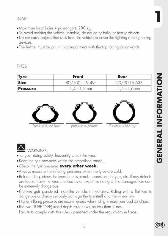
LOAD
•Maximum load (rider + passenger): 280 kg.•To avoid making the vehicle unstable, do not carry bulky or heavy objects.•Do not carry objects that stick from the vehicle or cover the lighting and signallingdevices.
•The helmet must be put in its compartment with the top facing downwards.
WARNING•For your riding safety, frequently check the tyres.•Keep the tyre pressures within the prescribed range.•Check the tyre pressures every other week.•Always measure the inflating pressures when the tyres are cold.•Before riding, check the tyres for cuts, cracks, abrasions, bulges, etc. If any defectsare found, have the tyres checked by an expert as riding with a damaged tyre canbe extremely dangerous.
• If a tyre gets punctured, stop the vehicle immediately. Riding with a flat tyre isdangerous and may seriously damage the tyre itself and the wheel rim.
•Higher inflating pressures are recommended when riding in maximum load condition.•The tyre (TUBE TYPE) tread depth must never be less than 2 mm.Failure to comply with this rule is punished under the regulations in force.
TYRES
Tyre Front Rear Size 80/100 - 19 49P 120/90-16 63P Pressure 1,4 ÷1,5 bar 1,5 ÷1,6 bar
Pressure is too low Pressure is too higtpressure is correct

1G
ENER
AL
INFO
RM
ATI
ON
10GB
FAMIALIARIZING WITH THE VEHICLE
1
2
34
5
7
8
9
19
20
13
14
10
15
16
12
17
11
11
18
21
22
24
25
24
17
6

1
GEN
ERA
L IN
FORM
ATI
ON
11 GB
FAMILIARIZING WITH THE VEHICLE:
1 - Air filter2 - Fuel tank3 - Filler cap4 - Silencer5 - Rear damper6 - Faro anteriore7 - Front turn signal lamp.8 - Tail lamp
9 - Rear turn signal lamp.
10 - Side stand11 - Rearview mirror12 - Passenger footrest13 - Fork14 - Footrest15 - Saddle16 - Engine17 - Front mudguard18 - Name-plate bracket19 - Start. lever20 - Helmet security lock21 - Frame22 - Chain23 - Chain guard24 - Front disk brake caliper25 - Rear disk brake caliper
1G
ENER
AL
INFO
RM
ATI
ON
12GB
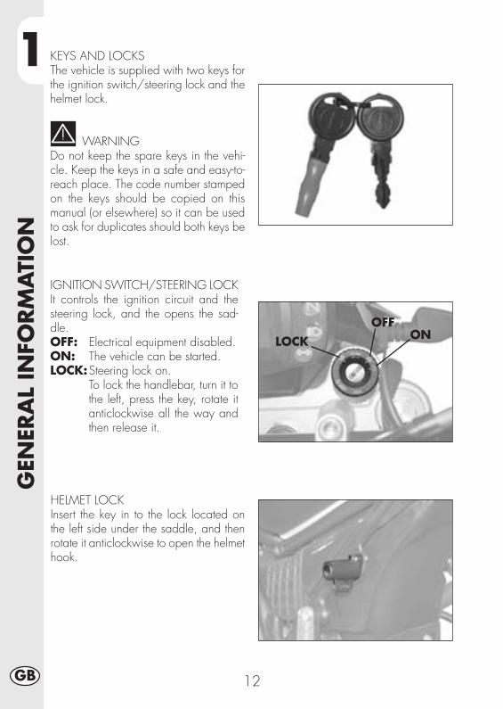
KEYS AND LOCKSThe vehicle is supplied with two keys forthe ignition switch/steering lock and thehelmet lock.
WARNINGDo not keep the spare keys in the vehi-cle. Keep the keys in a safe and easy-to-reach place. The code number stampedon the keys should be copied on thismanual (or elsewhere) so it can be usedto ask for duplicates should both keys belost.
IGNITION SWITCH/STEERING LOCKIt controls the ignition circuit and thesteering lock, and the opens the sad-dle.OFF: Electrical equipment disabled.ON: The vehicle can be started.LOCK:Steering lock on.
To lock the handlebar, turn it tothe left, press the key, rotate itanticlockwise all the way andthen release it.
HELMET LOCKInsert the key in to the lock located onthe left side under the saddle, and thenrotate it anticlockwise to open the helmethook.
ONOFF
LOCK

1
GEN
ERA
L IN
FORM
ATI
ON
13 GB
INSTRUMENT PANEL AND CONTROLS
Note: The lighting of the stand warning light indicates that the stand is down. Forsafety reasons, the engine stops as soon as the gears are engaged.
2
10
11
8
1
9
6
3
5
4
7
12
13
14
15
16
17
1- LCD2- Key operated switch3- Neutral indicator light4- Trafficator lights tell tale lamp5- Headlight tell tale lamp6- Tell tale lamp central stand7- SCROLL Pushbutton8- Clutch lever9- Choke unit lever (Urban125)
10- Front brake lever11 - Throttle twist grip12 - Starting button13 - Engine stop button14 - Direction indicators pushbutton15 - Horn button16 - Headlight selector17 - Passing
1G
ENER
AL
INFO
RM
ATI
ON
14GB
HOT TO SET AND USE THE ODOMETER
TABLE OF CONTENTS
ECTION CONTENT
10.0 Initial test and main screen
10.1 Warning lights
10.2 Instant speed and total distance (ODO)
20.0 Secondary functions
20.1 Trip odometer (TRP)
20.2 Clock (CLK)
20.3 Chronometer (LAP)
20.4 Max speed (MAX)
30.0 Storage

1
GEN
ERA
L IN
FORM
ATI
ON
15 GB
10.0 INITIAL TEST AND MAIN SCREEN
When turning the key or starting theengine, the instruments will turn on andwill show a general screen, with allindicators and warning lights On, for 3seconds:
Check-up page:It checks all the segments and icons onthe LCD and all the light indicators.
After the check-up page, the main screen(Figure 1) or the page that had last beenselected before turning off (see section20.0 and ff.) will appear.
(check)
Fig. 1

1G
ENER
AL
INFO
RM
ATI
ON
16GB
10.1 WARNING LIGHTS AND SCROLLBUTTON
The instrument is equipped with 4lights, which are both indicators andwarning light:
•’Stand’ red warning light A: whenOn, it means the side stand of thevehicle is down.
•’Neutral’ green warning light B: whenOn, it means the gear is in neutral.
• High-beam’ blue warning light C:when On, it means the high-beambulb is on.
•’Indicators’ green warning light D:when On, it means the indicators(right or left) are on.
• Scroll button E, used to move withinthe instrument to select the requiredfeatures (see section 20.0 and ff.)
A
B
C
DE

1
GEN
ERA
L IN
FORM
ATI
ON
17 GB
Fig. 1
Fig. 1A
10.2 PAGE 1 WITH TOTAL DISTANCECOVERED (ODO)
This is the main screen, which containsinformation about Instant speed, totaldistance covered (ODO) and the batteryvoltage bar:
•Instant speed:the Instant speed is displayed on 3digits, from 0 to 199 km/h (or from 0to 136 Mph).
• Total distance covered (ODO).The total distance covered by themotorbike is displayed in 5 digits, upto 99999. Such number cannot bereset.
•Battery voltage bar The battery voltage is displayed as onebar divided into 8 levels.
The battery icon blinks only when thebattery is exceeding the limit, as follows:
- when the first horizontal bar and thebattery icon blink (see Figure 1A), itmeans the voltage (*) is lower than theminimum admissible limit.
- When all bars and the battery icon blink,it means the voltage (*) is higher thanthe maximum admissible limit.
WARNING: If the vehicle has no battery, the bar and the battery icon measurethe voltage of the electric generator!
In these cases, if the light keeps blinking, check the cause!

1G
ENER
AL
INFO
RM
ATI
ON
18GB
20.0 SECONDARY FUNCTIONS
The main screen provides access to the following secondary features, containinginformation in the following sequence:
Trip odometer (TRP)
Clock (CLK)
Chronometer (LAP)
Max speed (MAX)
In addition to the specific information, the screen will still show the instant speed andthe battery voltage bar/icon.
From the general screen (ODO), quickly press SCROLL to have access to the otherscreens. This means they will be displayed in the following sequence:
ODO -> TRP -> CLK -> LAP -> MAX
When pressing SCROLL when the max speed screen is on (MAX) the screen willgo back to the main page (ODO) and the sequence can be resumed anywhere.
WARNING:THE SCROLL BUTTON CANNOT BE PRESSED WHEN THE VEHICLE IS RUNNING,I.E. WHEN THE INSTANT SPEED IS OTHER THAN 0 km/h-mph.
THIS IS FOR THE DRIVER’S SAFETY.
1
GEN
ERA
L IN
FORM
ATI
ON
19 GB
Fig. 2
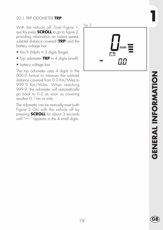
20.1 TRIP ODOMETER TRP
With the vehicle off, from Figure 1,quickly press SCROLL to go to figure 2,providing information on instant speed,subtotal distance covered (TRP) and thebattery voltage bar:
• Km/h (Mph) in 3 digits (large).
• Trip odometer TRP in 4 digits (small)
• battery voltage bar
The trip odometer uses 4 digits in the000.0 format to measure the subtotaldistance covered from 0.0 Km/Miles to999.9 Km/Miles. When reaching999.9, the odometer will automaticallygo back to 0.0 as soon as coveringanother 0.1 km or mile.
The odometer can be manually reset (withFigure 2 On) with the vehicle off bypressing SCROLL for about 3 secondsuntil “—.-“ appears in the 4 small digits.

1G
ENER
AL
INFO
RM
ATI
ON
20GB
Fig. 3
20.2 CLOCK CLK
From figure 2, with the vehicle off, quicklypress SCROLL to go to figure 3containing information on Instant speed,24h clock and battery voltage bar:
•Km/h in 3 digits (large)
•Clock in the hh:mm format in 4 digits(small)
•Battery voltage bar
The clock shows the time in the 24 hoursformat (from 0h:00’ to 23h:59’); it canbe set only when the vehicle is off, asfollows:
•Press SCROLL until the hour digits blink.
•Release and press SCROLL again tomove the hours forward by one unit ata time. Keep pressed to let themautomatically move on. Release to goto point 4.
•Release SCROLL after setting the hoursand wait: 2 seconds later, the minutedigits will start to blink.
•Proceed as described at point 2 to setthe minutes. Release SCROLL and wait2 seconds to save the minutes, then quitthe Clock mode.

1
GEN
ERA
L IN
FORM
ATI
ON
21 GB
Fig. 4
20.3 CHRONOMETER LAP
From figure 3, with the motorbike off,quickly press the button to go to figure 4,containing information on Instant speed,the chronometer in minutes:seconds andthe battery voltage bar:
•Km/h in 3 digits (large)
•Chronometer in the mm:ss format in 4digits (small)
• Battery voltage bar.
When the screen looks as in “Figure 4”,it means the chronometer must beactivated before it can be used. To dothis, press SCROLL and keep it pressedfor more than 1 second until “—:—“disappears and the chronometer appearsin the MINUTES:SECONDS format, asdescribed in figure 4A”
Fig. 4A

1G
ENER
AL
INFO
RM
ATI
ON
22GB
How to use: the chronometer can be started and stopped in manual and automaticmode when the instrument is set on “Figure 4A”:
• The chronometer can be manually started and stopped by quickly pressing thestart/stop button (only with the motorbike off).
• The chronometer is automatically started when the motorbike starts moving; itautomatically stops about 1 second after stopping the motorbike (the displayedfigure is automatically corrected).
The count will also stop when the motorbike stops after driving (even if manuallystarted), provided the LAP feature is On.
Fig. 4AThis figure shows the chronometer andthe count of the time: if the count is stilland reset, all the digits are set to zeroand displayed as in figure 4A.
A blinking “LAP” message means thechronometer is On and will be displayedeven while viewing the other informationpages.To set other functions not related to thechronometer even when the chronometeris on, proceed as follows.
How to reset the chronometer:Press SCROLL in figure 4A for more than2 seconds; this will highlight figure 4,then again figure 4A, with the timecounted the chronometer on it. ReleaseSCROLL to reset and stop thechronometer.
How to quit (turn off) the LAP fi-gure:From page 4A, press for 1 to 2 secondsuntil page 4 appears again, then releasethe button. Press the button quickly againto go to the next page. The chronometerkeeps working, if On, and LAP will blink.
1
GEN
ERA
L IN
FORM
ATI
ON
23 GB
Fig. 5
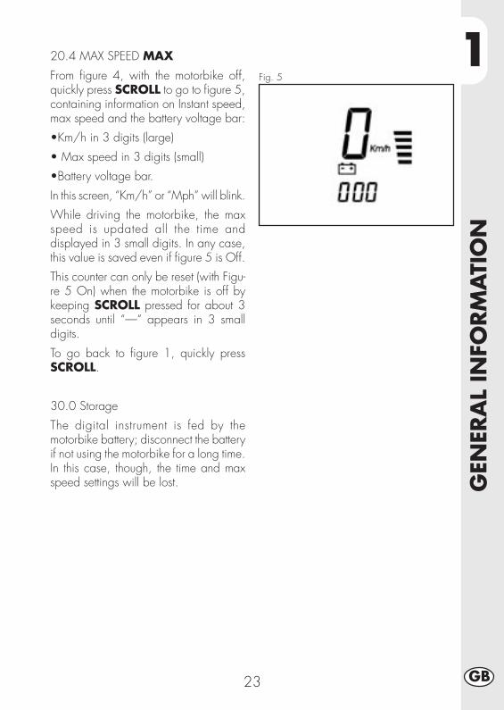
20.4 MAX SPEED MAX
From figure 4, with the motorbike off,quickly press SCROLL to go to figure 5,containing information on Instant speed,max speed and the battery voltage bar:
•Km/h in 3 digits (large)
• Max speed in 3 digits (small)
•Battery voltage bar.
In this screen, “Km/h” or “Mph” will blink.
While driving the motorbike, the maxspeed is updated all the time anddisplayed in 3 small digits. In any case,this value is saved even if figure 5 is Off.
This counter can only be reset (with Figu-re 5 On) when the motorbike is off bykeeping SCROLL pressed for about 3seconds until “—“ appears in 3 smalldigits.
To go back to figure 1, quickly pressSCROLL.
30.0 Storage
The digital instrument is fed by themotorbike battery; disconnect the batteryif not using the motorbike for a long time.In this case, though, the time and maxspeed settings will be lost.

1G
ENER
AL
INFO
RM
ATI
ON
24GB
SPECIFICATIONS
MAXIMUM LOADrider + passenger.......................................................................... 280 kg
VEHICLE’S KERB (DRY) WEIGHT URBAN 200 .................................... 103 kg
VEHICLE’S KERB (DRY) WEIGHT URBAN 125 ..................................... 101 kg
DIMENSIONSoverall length .......................................................................... 2,143 mm
overall width .............................................................................. 820 mm
overall height .......................................................................... 1,170 mm
wheelbase .............................................................................. 1,372 mm
saddle height ............................................................................. 836 mm
ground clearance ........................................................................ 288 mm
FRAME.............................................................. steel, double closed cradle
CAPACITIESfuel tank .............................................................................................. 6
including reserve ................................................................................ 1.5
average consumption .................................................................... 25 km/l

1
GEN
ERA
L IN
FORM
ATI
ON
25 GB
FRONT SUSPENSION
Hydraulic fork with Ø 37 mm.
Amount of oil per stem:
left ....................................................................................... 310 ± 5 cc
right ..................................................................................... 310 ± 5 cc
Oil type ............................................................................. SHELL EBH16
or LIQUI MOLY RECING SUSPENSION OIL SAE 10WOil level ......................................................... 142 mm from tube upper rim
with fork at end of travel and no spring
Trail ......................................................................................... 82,5 mm
REAR SUSPENSIONSingle progressive hydraulic shock absorber with adjustable rebound and springpreloadshock absorber travel ..................................................................... 63 mm
FRONT BRAKEØ 245 mm disc brake with hydraulic control
REAR BRAKEØ 220 mm disc brake with hydraulic control

1G
ENER
AL
INFO
RM
ATI
ON
26GB
ENGINE URBAN 125
Type ................................ Single-cylinder, forward-inclined, four-stroke, SOHC
Bore x stroke ............................................................................ 54X54 mm
Displacement .............................................................................. 124 cm3
Compression ratio ............................................................................. 10:1
Carburettor ....................................................MIKUNI UCAL 5Nh Ø 26-38
Lubrication ............................................................................... oil in sump
Fuel system .... petrol (unleaded, with a minimum octane number of 95), by carburettor
Cooling system ................................................................. by air circulation
Spark plug ........................................................................ NGK DR7 HSA
Clutch ..................................................................... multiple-disc in oil bath
transmission ............................................. 5-speed, with constant-mesh gears
Primary gearbox ratio ..................................................................... 68/20
Final gearbox ratio ......................................................................... 60/14
Gear ratios 1st ...................................................................... 37/14
2nd..................................................................... 32/18
3rd ..................................................................... 25/19
4th ...................................................................... 23/22
5th ...................................................................... 21/24
Drive chain ..................................................... REGINA 1/2, 5/16 P. 136
Play of valves ...................... intake mm 0.08 - 0.12 , exhaust mm 0,10 - 0,14
Starting ................................................................. electric and/or kick-start
Engine oil ............................................................. BARDAHL XTM15W 50
Engine oil capacity ...................................................... 1,000 ml/1,050 ml
1
GEN
ERA
L IN
FORM
ATI
ON
27 GB
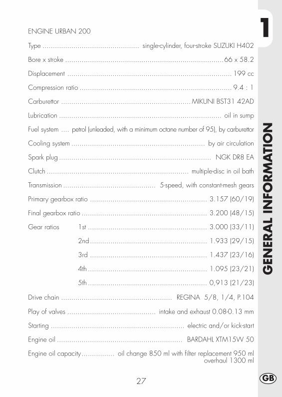
ENGINE URBAN 200
Type ............................................... single-cylinder, four-stroke SUZUKI H402
Bore x stroke .............................................................................66 x 58.2
Displacement ................................................................................ 199 cc
Compression ratio .......................................................................... 9.4 : 1
Carburettor ............................................................... MIKUNI BST31 42AD
Lubrication ............................................................................... oil in sump
Fuel system .... petrol (unleaded, with a minimum octane number of 95), by carburettor
Cooling system ................................................................. by air circulation
Spark plug .......................................................................... NGK DR8 EA
Clutch ..................................................................... multiple-disc in oil bath
Transmission ............................................. 5-speed, with constant-mesh gears
Primary gearbox ratio ......................................................... 3.157 (60/19)
Final gearbox ratio ............................................................. 3.200 (48/15)
Gear ratios 1st .......................................................... 3.000 (33/11)
2nd......................................................... 1.933 (29/15)
3rd ......................................................... 1.437 (23/16)
4th .......................................................... 1.095 (23/21)
5th .......................................................... 0,913 (21/23)
Drive chain ...................................................... REGINA 5/8, 1/4, P.104
Play of valves ........................................... intake and exhaust 0.08-0.13 mm
Starting ................................................................. electric and/or kick-start
Engine oil ............................................................. BARDAHL XTM15W 50
Engine oil capacity ................ oil change 850 ml with filter replacement 950 ml overhaul 1300 ml

1G
ENER
AL
INFO
RM
ATI
ON
28GB
SCHEMA ELETTRICO URBAN 125

1
GEN
ERA
L IN
FORM
ATI
ON
29 GB
WIRING DIAGRAM URBAN 1251) R.H. BLINKER (BULB 12V-10W)2) FRONT STOP PUSH BUTTON3) RIGHT CENTRAL UNIT4) ENGINE STOP5) STARTING BUTTON6) TELL TALE LAMP CENTRAL STAND7) NEUTRAL INDICATOR LIGHT8) HEADLIGHT TELL TALE LAMP9) TRAFFICATOR LIGHTS TELL TALE LAMP10) DISPLAY11) FRONT SENSOR WHEEL12) HEADLAMP (TWIN-LIGHT BULB 12V-5560W)13) SIDE LIGHT 12V-5W14) HORN BUTTON15) FLASH BUTTON16) HEADLIGHT SELECTOR17) TURN SIGNAL LAMPS SWITCH18) LEFT CENTRAL UNIT19) CLUTCH BUTTON20) AT COIL21) UNIT TURN SIGNAL LAMPS22) L.H. BLINKER (BULB 12V-10W)23) REGULATOR 12V24) CONDENSER25) STARTER MOTOR26) ENGINE CENTR.WEIGHT27) DIODE GR. 1A28) FUSE 15A29) REM. CONTROL SWITCH30) HERMETIC BATTERY 12V-9Ah31) L.H. BLINKER (BULB 12V-10W)32) PLATE ILLUMINATION (BULB 12V-5W)33) CENTR.WEIGHT34) POSITION35) STOP36) DIODE 1A37) TAIL LAMP (LED)38) R.H. BLINKER (BULB 12V-10W)39) REAR STOP PUSH BUTTON40) FUEL SENSOR41) SENSOR P.T.C.42) SENSOR STAND43) ENGINE CENTR.WEIGHT44) CONTACT, NEUTRAL SWITCH45) DIODE 1A46) PICK-UP47) ELECTRONIC CONTROL UNIT48) KEY OPERATED SWITCH49) HORN
Key to coloursBi = WhiteVe = GreenMa= BrawnVi = Purple
Bl = BlueNe = BlackGi = YellowRs = Red
Ar = OrangeAz = Sky-blueRo = PinKGr = Grey

1G
ENER
AL
INFO
RM
ATI
ON
30GB
SCHEMA ELETTRICO URBAN 200

1
GEN
ERA
L IN
FORM
ATI
ON
31 GB
Key to coloursBi = WhiteVe = GreenMa= BrownVi = Purple
Bl = BlueNe = BlackGi = YellowRs = Red
Ar = OrangeAz = Sky-blueRo = PinkGr = Grey
WIRING DIAGRAM URBAN 1251) R.H. BLINKER (BULB 12V-10W)2) FRONT STOP PUSH BUTTON3) RIGHT CENTRAL UNIT4) ENGINE STOP5) STARTING BUTTON6) TELL TALE LAMP CENTRAL STAND7) NEUTRAL INDICATOR LIGHT8) HEADLIGHT TELL TALE LAMP9) TRAFFICATOR LIGHTS TELL TALE LAMP10) DISPLAY11) FRONT SENSOR WHEEL12) HEADLAMP (TWIN-LIGHT BULB 12V-5560W)13) SIDE LIGHT 12V-5W14) HORN BUTTON15) FLASH BUTTON16) HEADLIGHT SELECTOR17) TURN SIGNAL LAMPS SWITCH18) LEFT CENTRAL UNIT19) CLUTCH BUTTON20) L.H. BLINKER (BULB 12V-10W)21) UNIT TURN SIGNAL LAMPS22) AT COIL23) REGULATOR 12V24) DIODE GR. 1A25) FUSE 15A26) ENGINE CENTR.WEIGHT27) STARTER MOTOR28) CONDENSER 4700μ F-25V29) DIODE 6A30) REM. CONTROL SWITCH31) HERMETIC BATTERY32) L.H. BLINKER (BULB 12V-10W)33) PLATE ILLUMINATION (BULB 12V-5W34) CENTR.WEIGHT35) POSITION36) STOP37) Nº2 DIODE 1A38) TAIL LAMP (LED)39) R.H. BLINKER (BULB 12V-10W40) REAR STOP PUSH BUTTON41) FUEL SENSOR42) SENSOR P.T.C.43) SENSOR STAND44) ENGINE CENTR.WEIGHT45) CONTACT, NEUTRAL SWITCH46) PICK-UP47) ELECTRONIC CONTROL UNIT48) KEY OPERATED SWITCH49) HORN
1G
ENER
AL
INFO
RM
ATI
ON
32GB
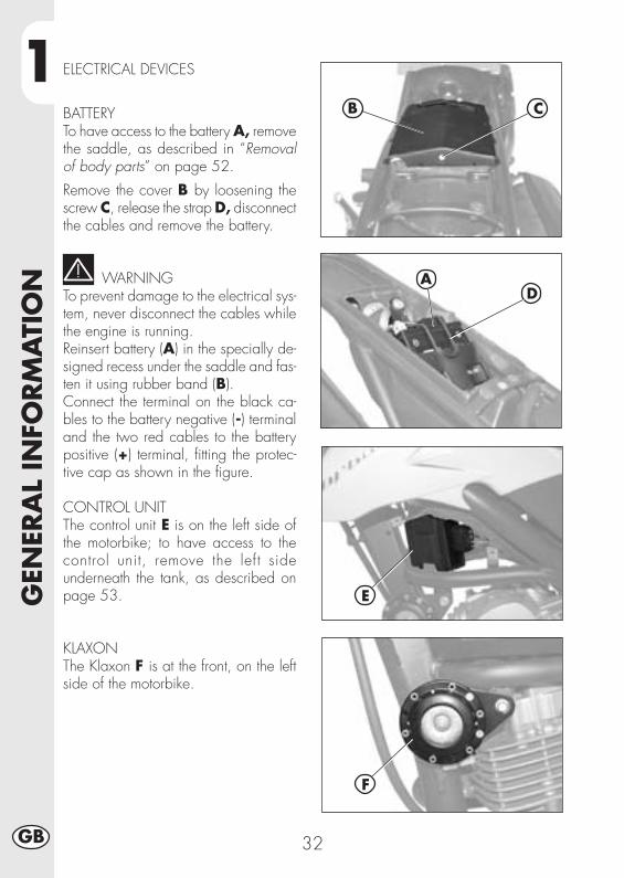
ELECTRICAL DEVICES
BATTERYTo have access to the battery A, removethe saddle, as described in “Removalof body parts” on page 52.
Remove the cover B by loosening thescrew C, release the strap D, disconnectthe cables and remove the battery.
WARNINGTo prevent damage to the electrical sys-tem, never disconnect the cables whilethe engine is running.Reinsert battery (A) in the specially de-signed recess under the saddle and fas-ten it using rubber band (B).Connect the terminal on the black ca-bles to the battery negative (-) terminaland the two red cables to the batterypositive (+) terminal, fitting the protec-tive cap as shown in the figure.
CONTROL UNITThe control unit E is on the left side ofthe motorbike; to have access to thecontrol unit, remove the left sideunderneath the tank, as described onpage 53.
KLAXONThe Klaxon F is at the front, on the leftside of the motorbike.
AD
E
F
B C

1
GEN
ERA
L IN
FORM
ATI
ON
33 GB
FLICKERINGThe flickering system G is under the tank;to have access to it, remove the right sideunderneath the tank, as described onpage 53.
HV REEL – STARTER RELAY – STANDRELAY - FUSEThe reel H, the starter relay I, the standrelay L and the fuse M are centrallylocated on the left side of the motorbike.The left side contains:- The klaxon,- The indicators,- The instruments,- Engine ignition.
Notes:Any burnt fuse must be replaced with anequivalent one. If the new fuse burns outtoo, contact a BETAMOTOR licensedgarage.The fuse’s capacity is 15 Ampere.
WARNING:Never fit a fuse of a higher power or tryto ‘repair’ it; an improper repair coulddamage the whole electric system.
VOLTAGE REGULATORThe voltage regulator N is centrallylocated.
G
H
L
N
I
M

1G
ENER
AL
INFO
RM
ATI
ON
34GB
A
AIS VALVEIt is called AIS valve and is an air inflowsystem that completes the combustion ofthat part of un-burnt hydrocarbons thatare the by-product of the thermodynamiccycle.
To have access to the valve A, removethe right guard under the tank, asdescribed on page 52

2
OPER
ATI
ON
35 GB
CONTENTS
CHAPTER 2 OPERATION
Checks and maintenance before and after off-road use
Recommended lubricants and fluids
Running-in
Starting the engine
Shutting off the engine
Refuelling

2O
PER
ATI
ON
36GB
CHECKS AND MAINTENANCE OPERATIONS BEFORE AND AFTER OFF-ROADUSE
To avoid trouble during operation, it is advisable to perform a few checks andmaintenance operations before and after riding. In addition to making your vehiclesafer, a few minutes spent carrying out these operations will enable you to save timeand money.Follow these steps:
TYRES Check the inflating pressures, the general condition, and thetread depth (see page 9).
SPOKES Check the tensioning.NUTS AND BOLTS Check the tightening of all nuts and bolts.DRIVE CHAIN Check the tension (play = 20 mm) and if necessary grease.AIR FILTER Clean the filter and wet it with oil (see page 48).
NoteCheck for the presence of the vehicle identification papers.In cold weather, it is advisable to warm up the engine by letting it idle for a fewmoments before starting off.The vehicle needs to be carefully washed every time it is used over rough ground.

2
OPER
ATI
ON
37 GB
PRODUCT TYPE SPECIFICATIONS
ENGINE OIL BARDAHL XTM 15W 50
BRAKE OIL BARDAHL BRAKE FLUID DOT4
FORK OIL SHELL EBH 16
TIE ROD GREASE BARDAHL Outboard Grease NLGI2
RECOMMENDED LUBRICANTS AND FLUIDS
To maximize the vehicle’s performance and ensure many years of trouble-free opera-tion, we recommend using the following products:
NoteIt is essential that all renewals should be performed with the products listed in detable above (see pag. 57).
RUNNING-IN
The running-in period lasts approximately 10 hours, during which it is advisable to:•Warm up the engine well before starting off.•Avoid riding at constant speed (changing the speed allows the different compo-nents to bed in uniformly and in a shorter time).
•Avoid turning the throttle twist grip more than 3/4 of its travel.
WARNING•After the first 1000 km renew the engine oil.•Always use high-octane unleaded petrol.•After using the vehicle on rough ground for the first time, carefully check the tighten-ing of all nuts and bolts.

2O
PER
ATI
ON
38GB
SHOW TO START THE ENGINE
• Turn the fuel tank tap to OPEN (seedrawing across).
• Turn the key switch clockwise and makesure the neutral warning light on theswitchboard is On (see ref. 3 on page13).
• Make sure the emergency switch A,on the gas control, is ON.
Important:When the engine is could, use choke D.
Electric starterPull the clutch lever while pushing thestarter button B on the gas control, with-out turning the gas grip.
Kick-starterUse the starter lever C; push the foot downhard, then fold back the lever.
Note:The engine can be started when the standis down and the red warning light on theswitchboard is On, provided the gearpedal is in neutral, as shown by the greenwarning light on the instrument panel.For safety reasons, if the motorbike is putinto gear even if the clutch is on, the en-gine will turn off.Then, close the stand and put the motor-bike into gear.
Note:The engine can also be started when thestand is down provided that the neutralindicator is lit.
A
ON OFF
B
C
Open Closed Reservoir

2
OPER
ATI
ON
39 GB
STARTER
The starter is used to start the motorbikemore easily even when the engine iscold; to use this device, proceed asfollow:
•Pull out starting device knob D, locatedon the left side of the carburettor, untilthe second click is heard.
•On URBAN125 models, starter leverD can only be operated after press-ing it inwards.
•Wait about 2 minutes to warm up theengine, without turning the gas grip,then bring the starter D to the initialposition.
SHUTTING OFF THE ENGINE
•While the vehicle is stationary and inneutral gear, rotate the ignition key tothe “OFF” position.
•Before stopping the engine after a longride, it is advisable to let it idle for afew moments.
• With the engine off, turn the fuel tapto CLOSED.
Open Closed Reservoir
D
D
URBAN125
URBAN200

2O
PER
ATI
ON
40GB
REFUELLING
•Switch off the engine.•Remove cap A.
NoteThe fuel tank capacity is approximately6 litres, including 1 litres reserve.
WARNING:Gasoline is extremely flammable.
Immediately remove any leak of gaso-line from the body or any other part.
Before refuelling, turn off the engine.
Do not let the gasoline leak out of thetank whi le refuelling.
Do not get close to the filler neck withnaked flames or lighted cigarettes.
Do not inhale harmful fuels.
A

3
CH
ECK
S A
ND
MA
INTE
NA
NCE
41 GB
CONTENTS
CHAPTER 3 CHECKS AND MAINTENANCE
Engine oil and oil filter
Fume collecting tube
Brake pump oil - Bleeding the brakes
Fork oil
Air filter
Spark plug
Front and rear brakes
Battery
Removing the bodywork
Notes for trial use
Cleaning and checking the vehicle
Scheduled maintenance
Prolonged inactivity

3CH
ECK
S A
ND
MA
INTE
NA
NCE
42GB
ENGINE OIL AND OIL FILTER URBAN 200
CheckKeep the vehicle in an upright position.Check the oil level through oil level sightA when the engine is cold. The oil levelmust never fall below the sight. If neces-sary, top up after removing filler cap B.
Topping upOnly top up after checking the max levelshown on sight A.
RenewalAlways renew the oil when the engine ishot. To avoid burns, take care not to touchthe engine and the oil.•Replace the oil when replacing the oilfilter.
•Put the vehicle on its stand.• Put a container under the engine, rightunder the drain plug D.
•Unscrew filler plug B and drain plug D.•Drain all the oil from the crankcase.•Close plug D.•Remove the oil filter cover after unscrew-ing the three nuts C.
•Remove the oil filter and replace it witha new one.
•Apply a thin film of engine oil to thefilter cover O-ring before insertion.
•Apply a film of engine oil over the filtercover O-ring before fitting it.
B
A
C
D

3
CH
ECK
S A
ND
MA
INTE
NA
NCE
43 GB
•Fit the oil filter cover after fitting the springand the O-ring, and then tighten the threefastening nuts C.
•Fill in with the right amount of oil:
- Oil replacement 850 ml- With filter replacement 950 ml- Overhaul 1300 ml
•Close the inlet plug B again.dle for afew minutes.
•Turn off the engine and wait for aboutone minute, then check the level and topup if needed, without exceeding the maxlevel shown on the window A.
NoteRenew the oil after the first 1,000 km.Subsequent renewals should be every5,000 km 15 months, (refer to the tableon page 57). Always use the lubricantsshown on page 37.The oil filter should be replaced for the firsttime when the oil is first renewed, and sub-sequently every 10,000 km (30 months).
IMPORTANTDispose of used oil in compliance with theregulations in force.

3CH
ECK
S A
ND
MA
INTE
NA
NCE
44GB
ENGINE OIL AND OIL FILTER URBAN125
CheckKeep the vehicle in an upright position.The engine is cold, check for the pres-ence of oil.
Topping upTo restore the level, remove cap A andtop up.
RenewalAlways renew the oil when the engine ishot. To avoid burns, take care not to touchthe engine and the oil.•Put the vehicle on its stand.•Extract the two screws D and fasteningE, and then remove protection C.
•Place a container under the engine.•Unscrew filler plug A and drain plug B.•Drain all the oil from the crankcase.•Close plug B.•Pour in 1000 cc of fresh oil.•Screw on filler cap A again.
WARNINGHot oil can cause severe burns.
Note:the URBANI25 engine contains the rotaryoil filter, which is mounted on the clutchside of the drive shaft. To replace it,contact a licensed Betamotor dealer.Note:Renew the engine oil after the first 500km. For the renewal intervals, refer to thetable on page 57. Only use the lubri-cants recommended on page 37.
IMPORTANTDispose of used oil in compliance withthe regulations in force.
A
B

3
CH
ECK
S A
ND
MA
INTE
NA
NCE
45 GB
FUME COLLECTING PIPEFume collecting tube A is located on the leftside of the vehicle next to the shock absorber.It comes out of the lower part of the Intakesleeve and is designed to collect the fumesproduced by the engine oil. It is designed tocollect the fumes produced by the engine oil.Should any oil be found in the tube, removethe cap at the lower end of the tube and drainthe oil, or the mixture of oil and petrol, into asuitable container. Disposal is to be made ac-cording to the regulations in force.NoteEmpty the fume collecting tube every 3,000 km.
IMPORTANTDispose of used oil in compliance with theregulations in force.
BRAKE PUMP OIL - BLEEDING THE BRAKESFront brakeCheck that oil is present by looking through oillevel sight B. The minimum oil level shouldnever be lower than the mark on sight B. Torestore the oil level, loosen the two screws C,lift cover D and pour in fresh oil.Rear brakeCheck the oil level through the level lightE. The min oil level must never drop belowthe mark shown by the warning light E.To fill up, loosen the two screws F, lift theplug G and pour in the oil.
WARNINGA spongy feel of the brake lever may bedue to an air bubble in the braking sys-tem. Immediately contact an authorizedworkshop. In this case, bleed any air outof the braking circuit.NoteFor information on oil renewals, refer tothe table on page 57. Use the recom-mended lubricants shown on page 37.
A
D
C
B
F
EG

3CH
ECK
S A
ND
MA
INTE
NA
NCE
46GB
Bleeding the front brakeFollow these steps to bleed the front brakecircuit:•Remove rubber cap A from valve B.•Remove the oil reservoir cap C.• Insert one end of a small tube into valveB and place the other end in a con-tainer.
•Unscrew valve B (while pulling the le-ver) and then pump by repeatedly actu-ating the brake lever until oil starts flow-ing out continuously with no air bubbles.During this operation, it is important thatthe lever should not be released com-pletely and that the brake pump reser-voir should be continuously refilled tomake up for the oil that is flowing out.
•Tighten the valve and extract the tube.•Replace the cap in gomma A.
Bleeding the rear brakeFollow these steps to bleed the rear brakecircuit:•Remove rubber cap D.•Remove the oil reservoir cap E.• Insert one end of a small tube into valveF and place the other end in a con-tainer.
•Unscrew valve F (while pulling the le-ver) and then pump by repeatedly actu-ating the brake lever until oil starts flow-ing out continuously with no air bubbles.During this operation, it is important thatthe lever should not be released com-pletely and that the brake pump reser-voir should be continuously refilled tomake up for the oil that is flowing out.
DF
A
B
C
E

3
CH
ECK
S A
ND
MA
INTE
NA
NCE
47 GB
FORK OIL
Right-hand rodsThe procedure for changing the oil in theforks is provided only for information. Werecommend having the operation per-formed by a BETAMOTOR authorizedworkshop.Follow these steps to renew the oil:1) Loosen rod clamping screw A.
2) Remove the lower plug (Allen screwin the legging) and upper plug B.
3) Let all the oil drain from the rod.
4) Fit and tighten the legging lower plug.
5) Pour in fresh oil of the type shown inthe table on page 37.
6) Fit and tighten upper plug B.
7) Retighten rod clamping screw A.
Note:The oil change procedure applies to boththe left and the right fork legs.
A
B

3CH
ECK
S A
ND
MA
INTE
NA
NCE
48GB
AIR FILTER
To have access to the filter unit A, removethe saddle, as described in “Removal ofbody parts” on page 52.
• Remove the cover B by loosening thescrew C.
• Lift the battery holder, as shown in thefigure,
• Release the filter holder D.• Remove the filter unit A.• Pull out the holder D and take out thesponge filter.• Wash it with soap and water.• Dry the filter.•Wet the filter with filter oil. Remove any ex-
cess lubricant to prevent it from dripping.• If necessary, also clean the inside of the
filter casing.• Refit the parts, making sure of the seal of
the rubber gasket.
Note:If the filter is very dirty, first wash it with aspecial detergent and then with water andshampoo.If the filter is damaged, immediately re-place it.Clean the filter every time the vehicle isused off road.
WARNING:After working on the filter, ensure that noth-ing is left inside the filter casing.
D
A
B C
DA

3
CH
ECK
S A
ND
MA
INTE
NA
NCE
49 GB
SPARK PLUG
To avoid burns, put on pro-tective gloves before per-forming the operation.
Keeping the spark plug in good condi-tion makes for reduced consumption andoptimum engine performance.It is advisable to remove the spark plugwhen the engine is hot (and naturally off)because the carbon formation and thecolour of the insulator provide importantinformation on carburetion, lubrication,and the general condition of the engine.If the insulator appears white, the mixtureis probably too lean; conversely, a greeninsulator denotes a rich mixture. The mix-ture is correct when the insulator is tan col-oured.To carry out the check, simply removethe current cap and then unscrew thespark plug using the spanner provided.Carefully clean the electrodes using awire brush. Blow the spark plug with com-pressed air to prevent any residues fromgetting into the engine.Measure the spark gap with a thicknessgauge. The gap should be 0.6-0.7 mm.If the gap is not as specified, restore theproper gap by bending the earth elec-trode.
Check that the insulator is not crackedand that the electrodes are not corroded,in which case the spark plug should beimmediately replaced.
Conduct the check by referring to the table on page 57.
Note:Lubricate the spark plug thread, and then(when the engine is cold) screw in thespark plug by hand to its abutting end.Finally tighten the spark plug with thespanner.
Note:•Always use spark plugs:URBAN 200 = NGK DR8 EAURBAN 125 = NGK CR7 HSA

3CH
ECK
S A
ND
MA
INTE
NA
NCE
50GB
FRONT BRAKE
CheckTo check the wear of the front brake, visu-ally inspect the brake pad ends by look-ing at the brake caliper from the front.The brake linings should be at least 2mm thick. If the linings are thinner, replacethe pads immediately.(see section 5, “Replacements”, on page 66).
NoteCarry out the check at the intervals shownin the table on page 57.
REAR BRAKE
CheckTo check the wear of the rear brake, visu-ally inspect the brake pad ends by look-ing at the brake caliper from above. Thebrake linings should be at least 2 mmthick. If the linings are thinner, replacethe pads immediately.(see section 5, “Replacements”, on page 66).
NoteCarry out the check at the intervals shownin the table on page 57.
2 mm
3
CH
ECK
S A
ND
MA
INTE
NA
NCE
51 GB
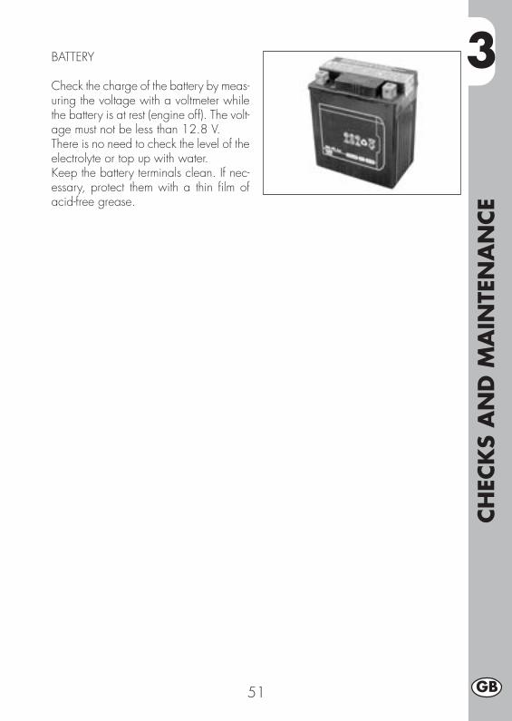
BATTERY
Check the charge of the battery by meas-uring the voltage with a voltmeter whilethe battery is at rest (engine off). The volt-age must not be less than 12.8 V.There is no need to check the level of theelectrolyte or top up with water.Keep the battery terminals clean. If nec-essary, protect them with a thin film ofacid-free grease.

3CH
ECK
S A
ND
MA
INTE
NA
NCE
52GB
HOW TO REMOVE BODY PARTS
Some parts of the body may have to beremoved for easier inspections or main-tenance.
WARNING:If these parts are improperly reassembled,they might suddenly come off while driv-ing, and the driver might lose control ofthe motorbike.
How to remove the saddleTo remove the saddle, just remove thetwo screws A, the clamp B and the clampC underneath the saddle.
Note:When removing the saddle the fenderwill come off too.To separate the two parts, remove thethree screws D.
How to remove the tank coversTo remove the tank covers E, proceed asfollows:
• Loosen the screws F on the tank.• Loosen the two clamps G, in the front
of the motorbike.• Remove the tank cover E.
F
E
G
A
B
C
D

3
CH
ECK
S A
ND
MA
INTE
NA
NCE
53 GB
How to remove the fuel tankRemove the saddle, then loosen the screw Hwhich secures the tank to the frame, removethe pipe of the fuel tap and take off the tankby pulling it out of the back.
How to remove the side framesTo remove the two side frames L underthe tank on both sides of the motorbike,just remove the two screws I.
How to remove the front lightholderRemove the lamp screws N, disconnectthe lamp wires, then remove the twoscrews M which secure the lamp-hold-ing unit.
H
L
I
N
M

3CH
ECK
S A
ND
MA
INTE
NA
NCE
54GB
A
B
E
D
F
G
H
I
How to remove the plate holderTo remove the back plate holder Aincluding the lights and indicators, firstremove the saddle (see previous page),then:•loosen the three screws and the fixingnuts B of the back plate holder.
•disconnect the electric connections of theback lights and remove the plate holder A.
WARNING:The motorbike cannot be driven
without a plate holder and/or lights. Itcan only be driven in private tracks and/or traffic-barred areas.
Removing the front mudguardRemove the front mudguard by unscrewingthe 4 fixing screw C.
Removing the stand•Remove the fixing system D (screw andnut).
•Pull out the stand E while taking carenot to lose the draw spring F.
Notes:while disassembling the motorbike, takecare not to damage the magnet and thestand sensor G.Removing the passenger’s footrests• Loosen the two screws Hshown in the fig-ure and remove the passenger’s footrestcomplete with the frame fixing support.
How to remove the helmet lockTo remove the helmet lock, just removethe two screws I.
C
3
CH
ECK
S A
ND
MA
INTE
NA
NCE
55 GB
I
M
O
N
L
M
P
O
URBAN200 URBAN125
URBAN200
URBAN125
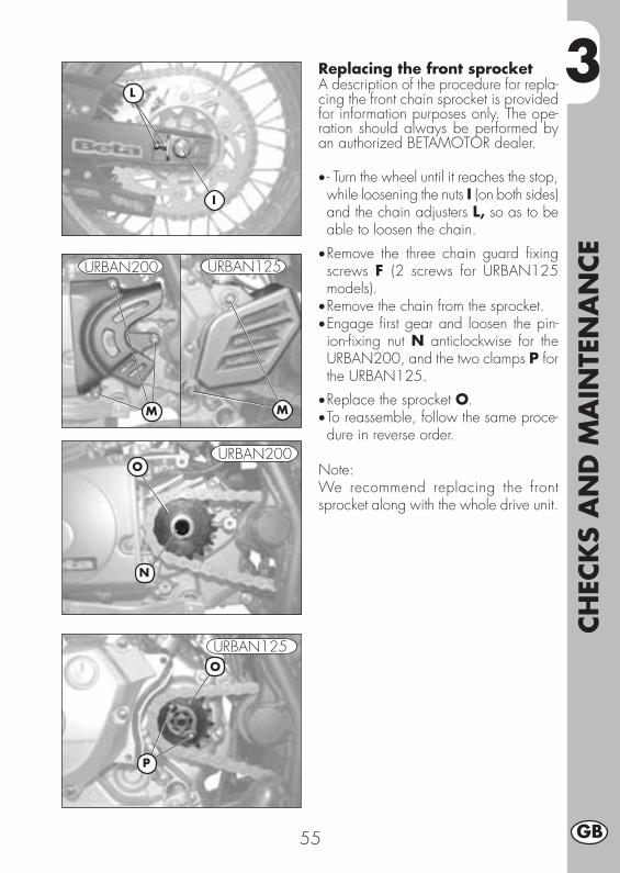
Replacing the front sprocketA description of the procedure for repla-cing the front chain sprocket is providedfor information purposes only. The ope-ration should always be performed byan authorized BETAMOTOR dealer.
• - Turn the wheel until it reaches the stop,while loosening the nuts I (on both sides)and the chain adjusters L, so as to beable to loosen the chain.
•Remove the three chain guard fixingscrews F (2 screws for URBAN125models).
•Remove the chain from the sprocket.•Engage first gear and loosen the pin-ion-fixing nut N anticlockwise for theURBAN200, and the two clamps P forthe URBAN125.
•Replace the sprocket O.•To reassemble, follow the same proce-dure in reverse order.
Note:We recommend replacing the frontsprocket along with the whole drive unit.

3CH
ECK
S A
ND
MA
INTE
NA
NCE
56GB
CLEANING AND CHECKING THE VEHICLE
Use a low-pressure water jet to soften the dirt and mud accumulated on the paintwork,then remove them with a soft bodywork sponge soaked in water and shampoo (2-4 percent shampoo in water). Rinse generously with water and wipe dry withchamois leather. For the outside of the engine use a brush soaked in petroleum andclean rags. Petroleum damages the paintwork. Always wash the vehicle beforewaxing it with silicon waxes.
Detergents pollute the waters. Always wash the vehicle in areas equippedfor the collection and purification of the washing liquids.
Never wash the vehicle in the sun, particularly during the summer when thebodywork is hot. The shampoo would dry before being rinsed off and causedamage to the paintwork. Do not clean the plastic surfaces with clothssoaked in petrol or naphtha as they would lose their shine and mechanicalproperties.
Water jets can damage the instruments; do not direct the jet towards theelectric parts, especially the LCD display.
CHECKS AFTER CLEANING
After cleaning the motorcycle, it is advisable to:
•Clean the air filter (refer to the procedure described on page 48).•Grease the chain.

3
CH
ECK
S A
ND
MA
INTE
NA
NCE
57 GB
SCHEDULED MAINTENANCE
Note
For any service requirements, please contact Betamotor’s Authorized Service Network.

3CH
ECK
S A
ND
MA
INTE
NA
NCE
58GB
AFTER PROLONGED INACTIVITY
•Reinstall the battery.•Restore the tyre inflating pressures.•Check the tightening of all the screws having an important mechanical function.
NotePeriodically check the tightening of the screws.
•Start the vehicle for the first time by means of the kick-start.
PROLONGED INACTIVITY
A few simple operations should be performed to keep the vehicle in good conditionwhenever it is to remain inactive for a long period (e.g. during the winter):
•Thoroughly clean the vehicle.•Reduce the tyre pressures by approxi-mately 30 percent, and if possible raisethe tyres off the ground.
•Remove the spark plug and pour a fewdrops of engine oil into the spark plughole. Make the engine turn a few timesby operating the kick-start (where avail-able) and then replace the spark plug.
•Cover the unpainted parts, exceptingthe brakes and the rubber parts, with afilm of oil or spray silicone.
•Remove the battery and keep it in a dryplace. Recharge the battery once amonth.
•Protect the vehicle with a dust cover.•Drain the carburettor float chamber byloosening screw A. The fuel drainedfrom the chamber through a suitablepipe must be collected in a containerand poured into the fuel tank. Do notdispose of the fuel in the environment.
•Retighten the screw.
A
A
URBAN200
URBAN125

4
AD
JUST
MEN
TS
59 GB
CONTENTS
CHAPTER 4 ADJUSTMENTS
Adjusting the brakes
Adjusting the clutch
Adjusting the slow running
Adjusting the throttle play
Checking and adjusting the steering play
Tensioning the chain
Adjusting the headlight

4A
DJU
STM
ENTS
60GB
ADJUSTING THE BRAKES
Front brakeThe front brake is a hydraulically oper-ated disc brake, and therefore requiresno adjustment.
Back brakeThe back brake is a hydraulically-operated disk brake, so it needs noadjustment.
ADJUSTING THE CLUTCHThe only operation that may be requiredis the adjustment of the position of clutchlever E.The adjustment is obtained by means ofadjuster D.After adjusting the lever with the adjust-ing screw, be sure to tighten stop F so asto lock the screw in the desired position.
NoteThe play of the clutch should range from0.4 to 0.6 mm.
FD E

4
AD
JUST
MEN
TS
61 GB
ADJUSTING THE SLOW RUNNINGURBAN200The slow running should be adjustedwhen the engine is hot. Connect an elec-tronic revolution counter to the spark plugcable. Tune up using adjusting screw A(idle speed = 1,400 ± 100 rpm).
ADJUSTING THE SLOW RUNNINGURBAN125The slow running should be adjustedwhen the engine is hot. Connect an elec-tronic revolution counter to the spark plugcable.Then turn adjusting screw C with a screw-driver until the engine idles at 1900 rpm.
FUEL FLOW ADJUSMENTURBAN125/200To adjust the fuel flow, loosen screw Dby one and a half turns from the fullyclosed position.Standard setting of adjuster: turn the ad-juster all the way in (clockwise), thenslacken 1,5 turns.
ADJUSTING THE THROTTLE PLAYIf the throttle control idle travel exceeds 3mm as measured on the rim of the twist grip,adjust the play by acting on adjuster B.
B
A
CD
URBAN200
URBAN125
D

4A
DJU
STM
ENTS
62GB
CHECKING AND ADJUSTING THESTEERING PLAY
Periodically check the play of the steer-ing head tube by moving the forks back-wards and forwards as shown in thefigure. If any play is felt, carry out theadjustment by following these steps:•Unscrew the four screws A.•Pull out handlebar B, paying specialattention to clevises C.
• Loosen nut D.• Loosen the two screws F.•Reduce the play by turning ring E.To refit the parts, follow the reverse pro-cedure.
NoteProper adjustment must leave no playand cause no stiffness, and allow thesteering to rotate smoothly. Check thefitting direction of the clevises as it canalter the geometry of the handlebar.
B
D
E C
A
F F
Note:The operration should always be per-formed by an authorized Betamotordealer.

4
AD
JUST
MEN
TS
63 GB
TENSIONING THE CHAIN
To ensure the drive chain a longer life, itis advisable to periodically check its ten-sion.Always maintain the chain clean and lu-bricated.If the chain play exceeds 20 mm, ten-sion the chain by following these steps:
•Loosen the nuts A on both branche ofthe big fork.
•Loosen the nut C on both branches ofthe big fork.
•Turn the nut B until the chain is properlystretched.
•Do the same with the nut B, which is onthe other branch of the big fork, untilthe wheel is perfectly aligned.
•Tighten the nuts B and A on bothbranches of the fork.
20 mm
B
C A

4A
DJU
STM
ENTS
64GB
ADJUSTING THE HEADLIGHT
•The headlight beam is adjusted manually after loosening the screws on either sideof the headlight with an Allen key.
•Periodically check the direction of the beam. The beam can only be adjustedvertically.
•Place the vehicle on level ground (but not on the stand) 10 metres from a verticalwall.
•Measure the height of the headlight centre above the ground and then draw across on the wall at 9/10 of the height of the headlight centre.
•Turn on the low beam, get on the motorbike and check that the headlight beam onthe wall is slightly lower than the cross drawn previously.
9/10
h
10 m
h
AA

5
REP
LACEM
ENTS
65 GB
CONTENTS
CHAPTER 5 REPLACEMENTS
Replacing the brake pads
Replacing the headlight bulb
Replacing the rear light bulb
Replacing the turn indicator bulbs
Bulbs characteristics
5REP
LACEM
ENTS
66GB
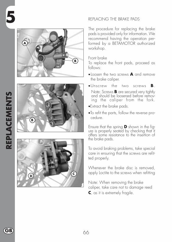
REPLACING THE BRAKE PADS
The procedure for replacing the brakepads is provided only for information. Werecommend having the operation per-formed by a BETAMOTOR authorizedworkshop.
Front brakeTo replace the front pads, proceed asfollows:
• Loosen the two screws A and removethe brake caliper.
•Unscrew the two screws B.Note: Screws B are secured very tightlyand should be loosened before remov-ing the caliper from the fork.
•Extract the brake pads.
•To refit the parts, follow the reverse pro-cedure.
Ensure that the spring D shown in the fig-ure is properly seated by checking that itoffers some resistance to the insertion ofthe brake pads.
To avoid braking problems, take specialcare in ensuring that the screws are refit-ted properly.
Whenever the brake disc is removed,apply Loctite to the screws when refitting
Note: When removing the brakecaliper, take care not to damage reedC, as it is extremely fragile.
CD
A
B
B
5
REP
LACEM
ENTS
67 GB
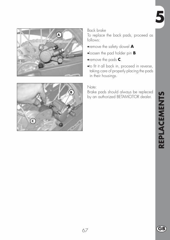
Back brakeTo replace the back pads, proceed asfollows:
•remove the safety dowel A
•loosen the pad holder pin B•remove the pads C.
•to fit it all back in, proceed in reverse,taking care of properly placing the padsin their housings.
Note:Brake pads should always be replecedby an authorized BETAMOTOR dealer.
A
B
C

5REP
LACEM
ENTS
68GB
REPLACING THE HEADLIGHT BULBTo replace the front lights, proceed asfollows:
- remove the two screws A that securethe light unit to the light holder.
- disconnect the electric connector B.
- lift the rubber casing C.- release the spring D.
- remove the faulty light and fit in a newone, taking care not to touch the bulbto avoid reducing its efficiency.
- to replace a parking light, just pull outthe bulb E and take out the faulty light.
- to fit it all back in, proceed in reverse.
Note:Any replacement lamp must meet thesame specifications as the original ones(see section, “Light specifications”, page76).
B
C
C
D
E
AA

5
REP
LACEM
ENTS
69 GB
REPLACING THE TURN INDICATORBULBS
To replace the plate number light,proceed as follows:
• Loosen the screw C.• Remove the transparent screen D.• Pull the faulty light out of the bulb andreplace with a new one.
• To fit it all back in, proceed in reverse.
Note:Any replacement lamp must meet thesame specifications as the original ones(see section, “Light specifications”, page76).
REPLACING THE REAR LIGHT BULB
To replace the back light unit A, proceedas follows:
• Remove the plate holder as describedin the section, “Removal of body parts”on page 60.
• Disconnect all electric connections.
• Loosen the two screws B under the fen-der.
• Pull out the faulty light unit A and replaceit with a new one.
• To fit it all back in, proceed in reverse.
Note:Any replacement lamp must meet thesame specifications as the original ones(see section, “Light specifications”, page76).
A
B
CD

5REP
LACEM
ENTS
70GB
REPLACING THE TURN INDICATORBULBSTo replace the indicator lights, proceedas follows:
•Loosen screw A and remove the lens.
•Remove the faulty light and replace witha new one.
Note:Any replacement lamp must meet thesame specifications as the original ones(see Table below).
A
A
Headlamp bulb 12V-55/60WPosition bulb 12V-5WTrafficator lights bulbFront/Rear
12V-6W
Taillight/stop bulb LEDNumber plate light 12V-5W
BULBS CHARACTERISTICS

6
TRO
UBLE
SHO
OTI
NG
71 GB
CONTENTS
CHARTER 6 TROUBLESHOOTING
INDEX

6TR
OU
BLE
SHO
OTI
NG
72GB
PROBLEM CAUSE
Engine does not start
REMEDY
- Fuel system clogged (fuel lines,fuel tank, fuel cock).
- Air filter dirty.
- No current supplied to sparkplug.
- Engine flooded.
Clean the system.
Proceed as described on page 48.
Clean or replace the spark plug. If theproblem persists, contact aBETAMOTOR dealer.
Open the throttle wide and try startingthe engine for a few moments. If thisdoes not solve the problem, remove thespark plug and dry it.
Engine misfires - Spark gap wrongly adjusted.
- Spark plug dirty.
- Spark advance excessive.
- Carbon formation in cylinder oron spark plug.
Restore the spark gap.
Clean or replace the spark plug.
Engine knocks Check the ignition timing.
Contact a BETAMOTOR dealer.
Engine overheats andloses power
- Silencer partly clogged.
- Exhaust port clogged.
- Ignition delayed.
Contact a BETAMOTOR dealer.
Contact a BETAMOTOR dealer.
Check the timing.
Front braking poor - Brake pads worn.
- Air or humidity in the hydrauliccircuit.
- Brake pads worn.
- Air or humidity in the hydrauliccircuit.
Follow the procedure described onpage 66.
Follow the procedure described onpage 46.
Follow the procedure described onpage 66.
Follow the procedure described onpage 46.
Rear braking poor
IND
EX
73 GB
Air filter ............................................................................................. 48
Brake pump oil ................................................................................... 45Brakes, adjustment .............................................................................. 60Brakes, bleeding ................................................................................. 45Brake pad check and replacement ......................................................... 66Bulbs, replacement .............................................................................. 68
Chain, tensioning ................................................................................ 63Checks after cleaning .......................................................................... 56Checks and maintenance before and after off-road use .............................. 36Clutch, adjustment ............................................................................... 60
Engine oil, check and renewal URBAN200 ............................................. 42Engine oil, check and renewal URBAN125 .............................................. 44
Fork oil .............................................................................................. 47
Helmet lock ........................................................................................ 12
Ignition switch/Steering lock ................................................................. 12Instrument panel and controls .................................................................. 13LCD ................................................................................................... 14
Keys ................................................................................................. 12
Recommended lubricants and fluids ........................................................ 37Refuelling........................................................................................... 40Running-in .......................................................................................... 37
Scheduled maintenance ....................................................................... 57Slow running, adjustment ...................................................................... 61Spark plug ......................................................................................... 49Specifications ..................................................................................... 24Starting ............................................................................................. 38Steering, check and adjustment ............................................................. 62
Throttle play, adjustment ....................................................................... 61Troubleshooting................................................................................... 71
Vehicle identification data ....................................................................... 8
Wiring diagrams URBAN125 ............................................................... 28Wiring diagrams URBAN200 ................................................................ 30