Embed Size (px)
Citation preview
I-HI-SPEED Rev 2.04
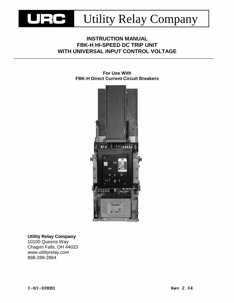
INSTRUCTION MANUAL
FBK-H HI-SPEED DC TRIP UNIT
WITH UNIVERSAL INPUT CONTROL VOLTAGE
For Use With
FBK-H Direct Current Circuit Breakers
Utility Relay Company 10100 Queens Way Chagrin Falls, OH 44023 www.utilityrelay.com 888-289-2864
Utility Relay
Company
Twinsburg, OH 44087 888-289-2864
www.utilityrelay.com URC Utility Relay Company
FBK HI-SPEED DC Trip Unit - Instruction Manual Rev 2.04
Items with an * are optional Page 1
Table of Contents Safety Notice .................................................................................................................. Page 2 1.0 Introduction ............................................................................................................................. 3 1.1 Safety ......................................................................................................................... 3 1.2 Part Number Guide ................................................................................................... 4 2.0 Features .................................................................................................................................. 5 3.0 Trip Unit ................................................................................................................................... 5 3.1 Current Measurement Algorithms ............................................................................. 5 3.2 User Input/Outputs .................................................................................................... 6 3.3 Normal Display .......................................................................................................... 7 3.4 Impulse Trip Coil Output ........................................................................................... 7 3.5 Auxiliary Contacts ...................................................................................................... 8 3.6 Remote Trip* ............................................................................................................. 8 3.7 Battery ....................................................................................................................... 9 4.0 Current Transducer ................................................................................................................. 10 5.0 Remote Display ....................................................................................................................... 11 6.0 Hi-Speed Trip Functions ......................................................................................................... 13 6.1 Hi-Speed Forward (FASTFOR) ................................................................................ 13 6.2 Hi-Speed Reverse* (FASTREV) ............................................................................... 13 6.3 Normal Current Direction .......................................................................................... 14 6.4 Remote Trip* ............................................................................................................. 14 7.0 Non-Hi-Speed Trip Functions ................................................................................................. 15 7.1 Long Time Trip* ......................................................................................................... 15 7.2 Long Time Delay* ...................................................................................................... 15 7.3 Short Time Trip* ........................................................................................................ 16 7.4 Short Time Delay* ..................................................................................................... 17 7.5 Rate-of-Rise Trip*...................................................................................................... 18 8.0 Loss of Control Voltage* (UV) ................................................................................................ 19 9.0 Settings 19 9.1 Reviewing Last Trip Data .......................................................................................... 19 9.2 Reviewing Settings .................................................................................................... 20 9.3 Changing Settings ..................................................................................................... 20 9.4 Transducer Rating Security Feature ......................................................................... 21 9.5 Clearing Last Trip Data ............................................................................................. 21 10.0 Testing & Calibrating ............................................................................................................... 22 10.1 Enter Desired Settings .............................................................................................. 22 10.2 Calibrate Transducer ................................................................................................. 22 10.2.1 4KA & 6KA Frame Breakers ......................................................................... 23 10.2.2 8KA, 10KA & 12KA Frame Breakers ............................................................ 24 10.3 Verify Pick-Up & Trip Times ...................................................................................... 25 10.4 Forced Trip ................................................................................................................ 25 10.5 Erase Last Trip Data ................................................................................................. 25 10.6 Displayed Messages ................................................................................................. 26 11.0 Ratings ................................................................................................................................... 26 12.0 Warranty .................................................................................................................................. 26
Figures 7 Block Diagram ........................................................................................................... 27 8 Non-Hi-Speed Trip Functions TCC ........................................................................... 28
THESE INSTRUCTIONS DO NOT PURPORT TO COVER ALL DETAILS OR VARIATIONS IN EQUIPMENT NOR TO PROVIDE FOR EVERY POSSIBLE CONTINGENCY TO BE MET IN CONNECTION WITH INSTALLATION, OPERATION, OR
MAINTENANCE. SHOULD FURTHER INFORMATION BE DESIRED OR SHOULD PARTICULAR PROBLEMS ARISE WHICH ARE NOT COVERED SUFFICIENTLY FOR THE PURCHASER’S PURPOSES, THE MATTER SHOULD BE REFERRED TO
UTILITY RELAY COMPANY.
FBK HI-SPEED DC Trip Unit - Instruction Manual Rev 2.04
Items with an * are optional Page 2
SAFETY NOTICE
DANGER: TURN OFF POWER SUPPLYING THE
EQUIPMENT BEFORE WORKING INSIDE THE BREAKER!!!
LETHAL VOLTAGE IS PRESENT INSIDE THE Hi-Speed Trip Unit
Installing, commissioning, maintaining, changing or refitting these units
must be carried out only by qualified and suitably trained specialist personnel
and under strict observation of national and international safety regulations.
Non-compliance with these warnings can result in death,
severe physical injury and extensive damage to the equipment.
The control circuits are partly equipped with capacitors
that may be charged with dangerous voltages.
Work on this section must be carried out carefully.
FBK HI-SPEED DC Trip Unit - Instruction Manual Rev 2.04
Page 3
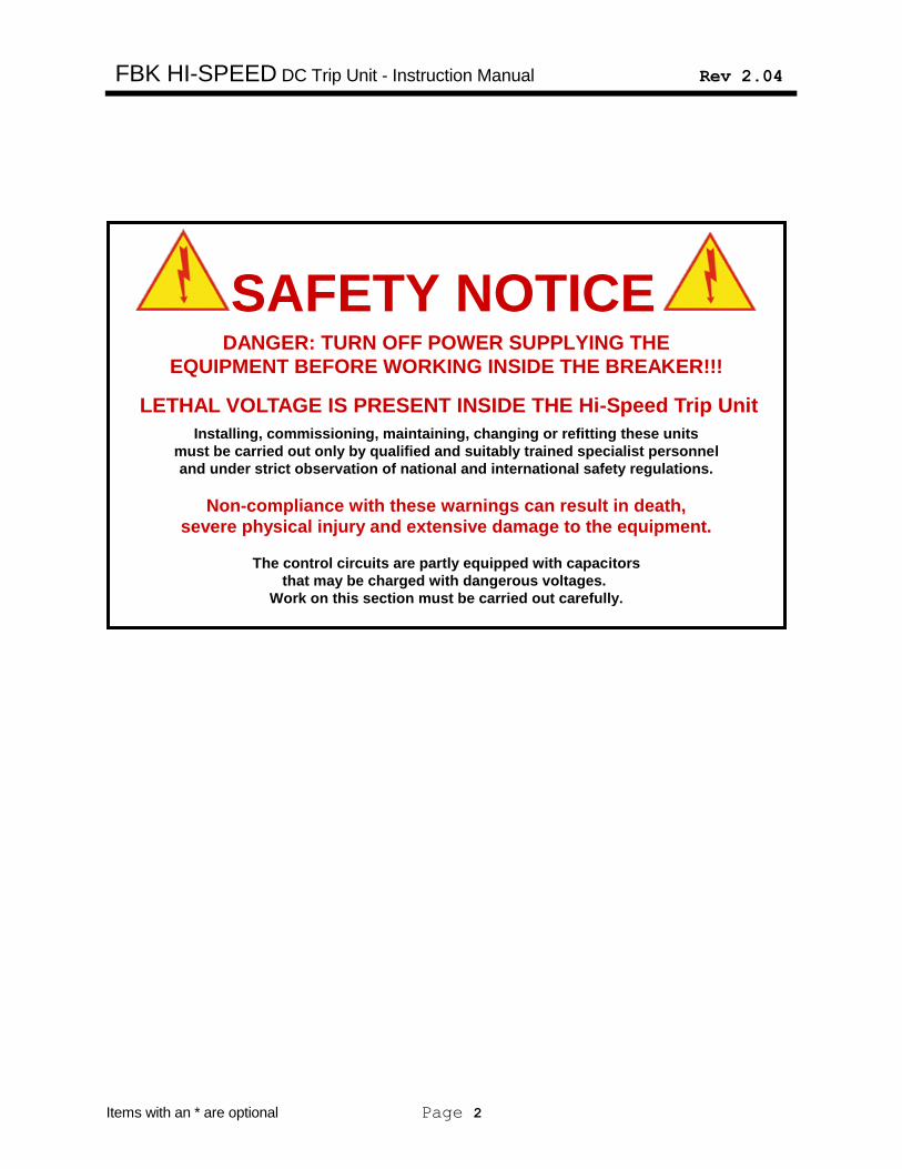
1.0 Introduction This manual applies to Hi-Speed trip units with hardware and firmware Rev. H26.30F4.12. The Hi-Speed DC Trip System is a state of the art, microcontroller based trip system intended for use on one and two pole FBK DC circuit breakers. The Hi-Speed DC Trip System provides bi-directional and directional overcurrent protection. For transit system applications, optional rate-of-rise protection is available. The Hi-Speed Trip System consists of 3 basic components:
A bi-directional Hall-effect current transducer
The trip unit
An impulse trip coil (optionally provided by Utility Relay Company)
The trip unit contains the following basic components:
Logic circuits that include analog and digital electronics and a microcontroller
User input/outputs: 16 character liquid crystal display (LCD) membrane type input push buttons two LED indicators
High voltage power supply
High voltage trip capacitor
A capacitor discharge system
An optional remote display unit for the breaker cubicle door
The trip unit provides the following trip functions: Bi-directional
Over load* (LT)
Short Time* (ST) Uni-directional
Hi-Speed Instantaneous Forward (FASTFOR)
Hi-Speed Instantaneous Reverse* (FASTREV)
Rate-of-Rise* (R/R)
The current transducer provides a signal to the trip unit proportional to the breaker current. The trip unit converts the transducer signal into amps for display on the LCD and also compares the current to the trip unit settings. If the trip unit determines that a trip is required, the trip capacitor that is charged to 2300 volts is discharged into the impulse coil. The impulse coil unlatches the breaker mechanism causing the breaker to open. The Hi-Speed DC Trip System has a universal control voltage input that is suitable for operation with the following control voltages:
120 volt AC 50/60Hz
125 volt DC
250 volt DC
1.1 Safety
Please note that lethal voltage is present inside the Hi-Speed trip unit. When control power is applied to the Hi-Speed trip unit, an internal high voltage capacitor is charged to 2300 volts. When control power is removed from the Hi-Speed trip unit the high voltage capacitor discharges to 50 volts in less than seven minutes. If the cover is ever removed from the Hi-Speed trip unit, the voltage on the high voltage
capacitor must first be measured no matter
how long the control power was removed.
If the high voltage capacitor voltage is 50
volts or less, the capacitor can be discharged
by shorting the capacitor terminals with an
insulated handle screwdriver. A safety
jumper should then be clipped onto the high
voltage capacitor terminals until the cover
will again be replaced.
FBK HI-SPEED DC Trip Unit - Instruction Manual Rev 2.04
Page 4
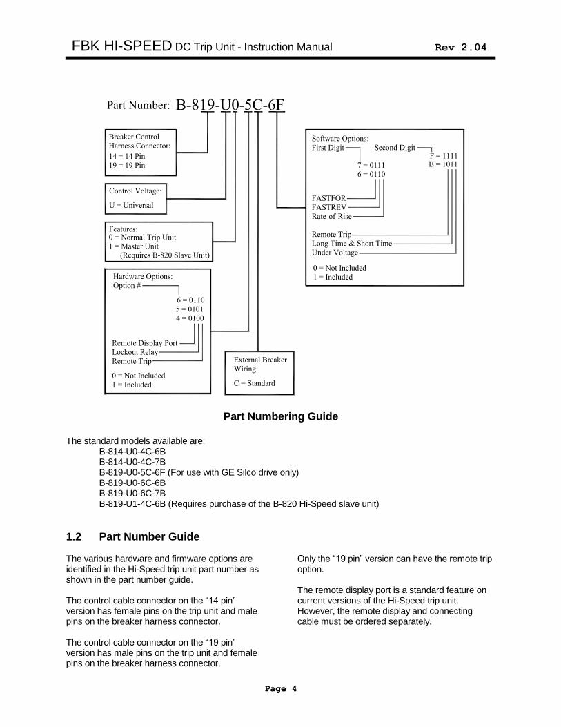
Part Number: B-819-U0-5C-6F
Breaker Control
Harness Connector:
14 = 14 Pin
19 = 19 Pin
Control Voltage:
U = Universal
Features:
Hardware Options:
Option #
6 = 0110
5 = 0101
4 = 0100
Remote Display Port
Lockout Relay
Remote Trip
0 = Not Included
1 = Included
External Breaker
Wiring:
C = Standard
Software Options:
First Digit Second Digit
7 = 0111
6 = 0110
FASTFOR
FASTREV
Rate-of-Rise
Remote Trip
Long Time & Short Time
Under Voltage
1 = Included
0 = Not Included
B = 1011F = 1111
0 = Normal Trip Unit
1 = Master Unit(Requires B-820 Slave Unit)
Part Numbering Guide
The standard models available are: B-814-U0-4C-6B B-814-U0-4C-7B B-819-U0-5C-6F (For use with GE Silco drive only) B-819-U0-6C-6B B-819-U0-6C-7B B-819-U1-4C-6B (Requires purchase of the B-820 Hi-Speed slave unit)
1.2 Part Number Guide The various hardware and firmware options are identified in the Hi-Speed trip unit part number as shown in the part number guide. The control cable connector on the “14 pin” version has female pins on the trip unit and male pins on the breaker harness connector. The control cable connector on the “19 pin” version has male pins on the trip unit and female pins on the breaker harness connector.
Only the “19 pin” version can have the remote trip option. The remote display port is a standard feature on current versions of the Hi-Speed trip unit. However, the remote display and connecting cable must be ordered separately.
FBK HI-SPEED DC Trip Unit - Instruction Manual Rev 2.04
Page 5
2.0 Features
The Hi-Speed DC Trip System offers the following features: a) Unique current sensing method provides
bi-directional current sensing with one transducer.
b) Displays last trip data for the three last
trip events including the current at the time of trip.
c) Trip log provides a record of the number
of trips for each trip function since last reset.
d) All settings are made directly in amps or
in seconds. e) Ease of coordination is provided with
settings that are made in extremely small increments.
f) 16 Character alphanumeric display with
backlight. g) An optional remote display for mounting
on the breaker cubicle door at a convenient viewing height.
The trip unit also incorporates several self-test features that continually monitor the trip system status. The green LED on the face of the trip unit provides a visual indication that the trip unit is operating properly. Self-test features include: 1) Watch-dog timer to ensure the micro-
controller is functioning properly.
2) Monitoring of the current transducer to ensure it is properly connected.
3) Monitoring of the high voltage trip capacitor charge.
3.0 Trip Unit
3.1 Current Measurement
Algorithms The trip unit uses a microcontroller to perform the DC current calculations and to implement the protection and logic functions.
For the non-hi-speed trip functions, the trip unit determines the DC current by averaging four A/D (analog to digital) samples of the current transducer signal at a 0.521 milli-second rate. The average value obtained is then multiplied by the current transducer rating to arrive at the breaker current in amps. This is the current used for the non-hi-speed trip functions and the current saved in the last trip data.
For the FASTFOR trip function, the microcontroller looks at each individual A/D sample of the current transducer signal in the forward direction and ignores current signals in
the reverse direction. For the FASTREV trip
function*, the microcontroller looks at each individual A/D sample of the current transducer signal in the reverse direction and ignores current signals in the forward direction. If two samples in a row for these functions are above the FASTFOR or FASTREV pick-up setting, the microcontroller initiates a trip. This entire procedure will take less than 1.5 milli-seconds. On the FBK breaker, the total time from fault inception to contact parting is less than 8 milli-seconds.
FBK HI-SPEED DC Trip Unit - Instruction Manual Rev 2.04
Page 6
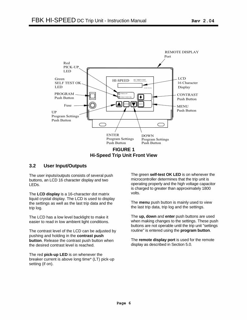
FIGURE 1
Hi-Speed Trip Unit Front View
3.2 User Input/Outputs The user inputs/outputs consists of several push buttons, an LCD 16 character display and two LEDs.
The LCD display is a 16-character dot matrix liquid crystal display. The LCD is used to display the settings as well as the last trip data and the trip log. The LCD has a low level backlight to make it easier to read in low ambient light conditions. The contrast level of the LCD can be adjusted by
pushing and holding in the contrast push
button. Release the contrast push button when the desired contrast level is reached.
The red pick-up LED is on whenever the breaker current is above long time* (LT) pick-up setting (if on).
The green self-test OK LED is on whenever the microcontroller determines that the trip unit is operating properly and the high voltage capacitor is charged to greater than approximately 1800 volts.
The menu push button is mainly used to view the last trip data, trip log and the settings.
The up, down and enter push buttons are used when making changes to the settings. These push buttons are not operable until the trip unit "settings
routine" is entered using the program button.
The remote display port is used for the remote display as described in Section 5.0.
FBK HI-SPEED DC Trip Unit - Instruction Manual Rev 2.04
Items with an * are optional Page 7
3.3 Normal Display
Breaker Current Less than 20% of
Transducer Rating: With the trip unit in service, and the breaker current less than 20% of the transducer rating, the display will show…
LOW CURRENT
Breaker Current Greater than 20% of
Transducer Rating: If the breaker current is greater than 20% of the transducer rating, the following will be shown on the display…
CURRENT XXXXX A
or…
REVERSE XXXXX A
If the breaker current is greater than the Long Time (LT)* pick-up setting (if on), the “PICK-UP” light on the front of the trip unit will illuminate, and the following will alternately be shown on the display at .5 second intervals:
CURRENT XXXXX A
OVERLOAD
3.4 Impulse Trip Coil Output As shown in Figure 7, the major components used to operate the impulse trip coil are a high voltage power supply, a high voltage capacitor and the trip circuit.
The high voltage capacitor is designed to handle the very high discharge currents into the impulse coil. The capacitor is made with a solid dielectric to eliminate problems associated with liquid dielectric capacitors. The capacitor is charged to 2300 volts but is rated at 3000 volts. A bleed resistor slowly discharges the capacitor when the high voltage power supply is turned off. The capacitor discharges to 50 volts in less than seven minutes after the control voltage is removed.
The high voltage power supply charges the capacitor to 2300 volts from the trip unit control voltage. It takes less than 4 seconds to charge the capacitor. The power supply is under the control of the microcontroller so that it only charges the capacitor when all conditions are proper.
The trip circuit discharges the high voltage capacitor into the impulse coil with a small signal from the microcontroller.
FBK HI-SPEED DC Trip Unit - Instruction Manual Rev 2.04
Items with an * are optional Page 8
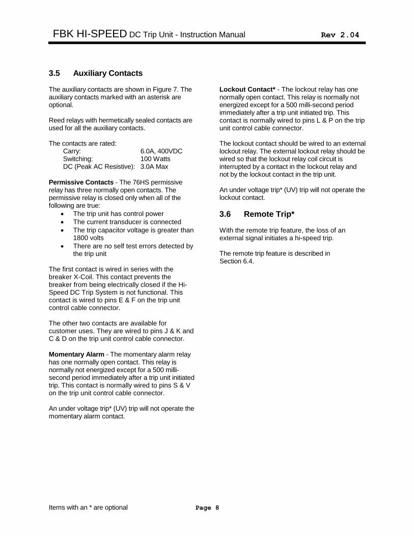
3.5 Auxiliary Contacts The auxiliary contacts are shown in Figure 7. The auxiliary contacts marked with an asterisk are optional. Reed relays with hermetically sealed contacts are used for all the auxiliary contacts. The contacts are rated: Carry: 6.0A, 400VDC Switching: 100 Watts DC (Peak AC Resistive): 3.0A Max
Permissive Contacts - The 76HS permissive relay has three normally open contacts. The permissive relay is closed only when all of the following are true:
The trip unit has control power
The current transducer is connected
The trip capacitor voltage is greater than 1800 volts
There are no self test errors detected by the trip unit
The first contact is wired in series with the breaker X-Coil. This contact prevents the breaker from being electrically closed if the Hi-Speed DC Trip System is not functional. This contact is wired to pins E & F on the trip unit control cable connector. The other two contacts are available for customer uses. They are wired to pins J & K and C & D on the trip unit control cable connector.
Momentary Alarm - The momentary alarm relay has one normally open contact. This relay is normally not energized except for a 500 milli-second period immediately after a trip unit initiated trip. This contact is normally wired to pins S & V on the trip unit control cable connector. An under voltage trip* (UV) trip will not operate the momentary alarm contact.
Lockout Contact* - The lockout relay has one normally open contact. This relay is normally not energized except for a 500 milli-second period immediately after a trip unit initiated trip. This contact is normally wired to pins L & P on the trip unit control cable connector. The lockout contact should be wired to an external lockout relay. The external lockout relay should be wired so that the lockout relay coil circuit is interrupted by a contact in the lockout relay and not by the lockout contact in the trip unit. An under voltage trip* (UV) trip will not operate the lockout contact.
3.6 Remote Trip* With the remote trip feature, the loss of an external signal initiates a hi-speed trip. The remote trip feature is described in Section 6.4.
FBK HI-SPEED DC Trip Unit - Instruction Manual Rev 2.04
Items with an * are optional Page 9
3.7 Battery A 9-volt, 1200 mAh, long life, lithium/manganese dioxide battery is incorporated in the trip unit. This battery has less than 2 grams of lithium. There are no restrictions on transport and no special methods of disposal required with this battery. The battery is not involved in the protective functions and it does not maintain any of the microcontroller memory. The battery performs the following two functions:
Allows the settings to be made and the last trip data to be reviewed without control power.
Allows the trip unit to save the last trip data with a UV* trip.
Lithium battery ratings:
Rated shelf life of ten-years
1200 mAh Capacity (Allows the review of last trip data and
settings over 1500 times on battery power only)
If it is necessary to replace the battery, use the following procedure. Only qualified personnel should remove the cover from the Hi-Speed trip unit. Follow the safety instructions in Section 1.1.
Remove the breaker from service
Remove the trip unit from the breaker
Wait at least 15 minutes to allow the high voltage capacitor to discharge
Remove the top cover of the trip unit and verify that capacitor has discharged to a safe voltage using a high voltage probe and follow the other safety instructions in Section 1.1 including the capacitor shorting jumper
Pop out the plastic battery cover by pulling the tab on the battery cover to the right
Replace the battery
Remove the capacitor shorting jumper
Reassemble the trip unit and reinstall on the breaker
For best performance, replace the battery with an Ultralife Model U9VL-J, 9-volt lithium battery. An alkaline type 9-volt battery may also be used with a much shorter life.
FBK HI-SPEED DC Trip Unit - Instruction Manual Rev 2.04
Items with an * are optional Page 10
4.0 Current Transducer
Zero Pot Calibration Pot
Connector
Factory set Factory set
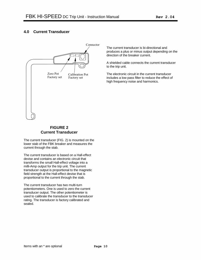
FIGURE 2
Current Transducer
The current transducer (FIG. 2) is mounted on the lower stab of the FBK breaker and measures the current through the stab. The current transducer is based on a Hall-effect devise and contains an electronic circuit that transforms the small Hall-effect voltage into a milli-Amp output for the trip unit. The current transducer output is proportional to the magnetic field strength at the Hall-effect devise that is proportional to the current through the stab. The current transducer has two multi-turn potentiometers. One is used to zero the current transducer output. The other potentiometer is used to calibrate the transducer to the transducer rating. The transducer is factory calibrated and sealed.
The current transducer is bi-directional and produces a plus or minus output depending on the direction of the breaker current. A shielded cable connects the current transducer to the trip unit. The electronic circuit in the current transducer includes a low pass filter to reduce the effect of high frequency noise and harmonics.
FBK HI-SPEED DC Trip Unit - Instruction Manual Rev 2.04
Items with an * are optional Page 11
5.0 Remote Display
AND SETTINGS
DISPLAYCONTRAST
ADJUST
PUSH TO VIEWLAST TRIP DATA
PUSH TO
SELF TEST OK
PICK-UP
MICRO-CONTROLLER BASEDHI-SPEED DISPLAY
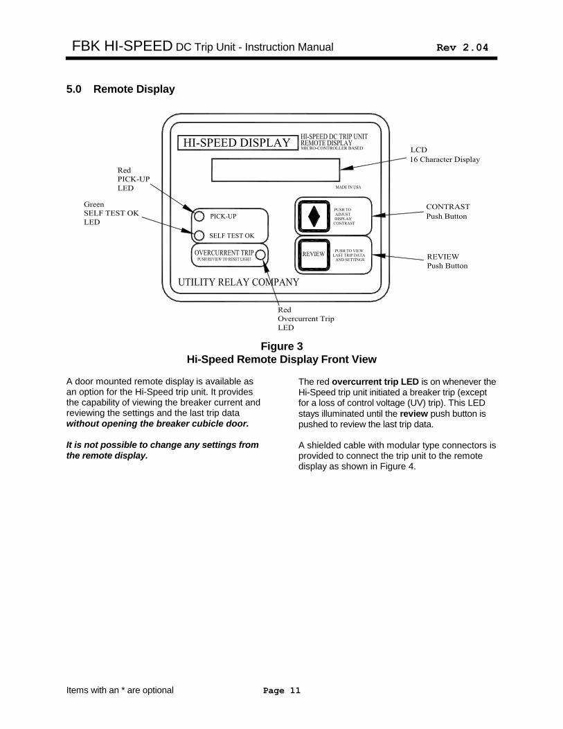
Figure 3
Hi-Speed Remote Display Front View A door mounted remote display is available as an option for the Hi-Speed trip unit. It provides the capability of viewing the breaker current and reviewing the settings and the last trip data without opening the breaker cubicle door. It is not possible to change any settings from the remote display.
The red overcurrent trip LED is on whenever the Hi-Speed trip unit initiated a breaker trip (except for a loss of control voltage (UV) trip). This LED
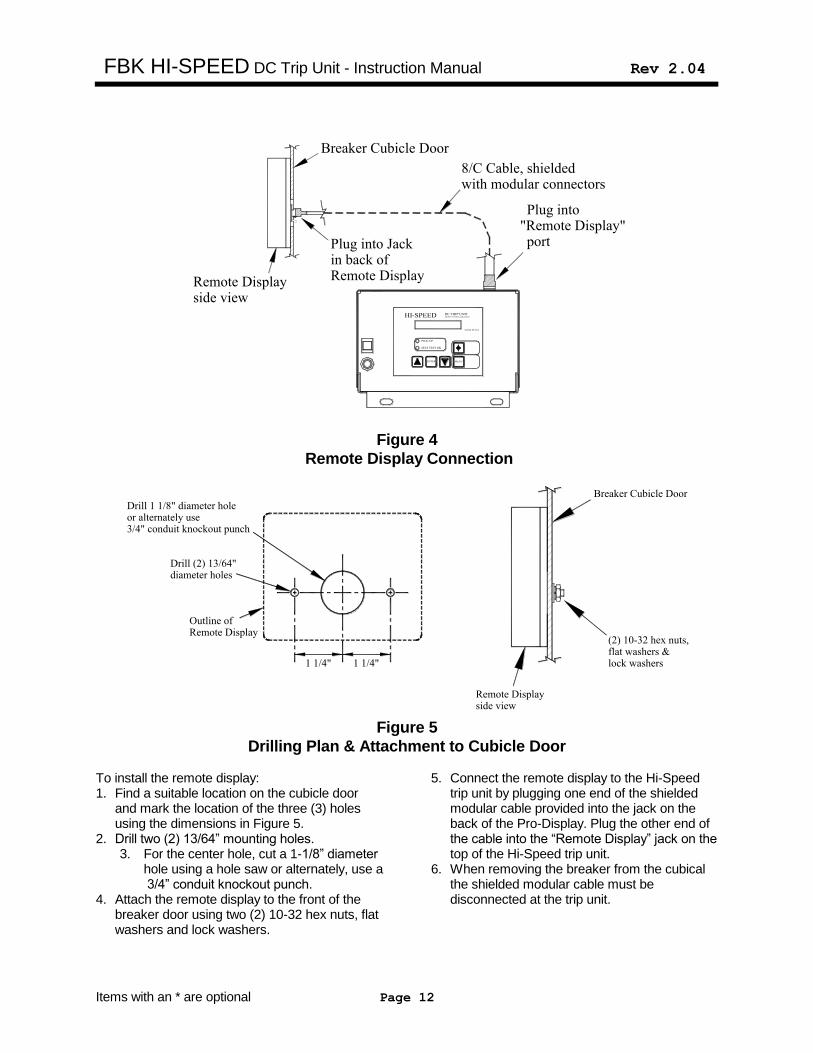
stays illuminated until the review push button is pushed to review the last trip data. A shielded cable with modular type connectors is provided to connect the trip unit to the remote display as shown in Figure 4.
FBK HI-SPEED DC Trip Unit - Instruction Manual Rev 2.04
Items with an * are optional Page 12
Plug into
Remote Display
Plug into Jack
side viewRemote Display
in back of
"Remote Display"port
Breaker Cubicle Door
with modular connectors8/C Cable, shielded
Figure 4
Remote Display Connection
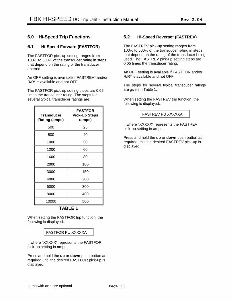
diameter holesDrill (2) 13/64"
Remote DisplayOutline of
or alternately useDrill 1 1/8" diameter hole
3/4" conduit knockout punch
1 1/4" 1 1/4"
Breaker Cubicle Door
Remote Displayside view
(2) 10-32 hex nuts,flat washers &lock washers
Figure 5
Drilling Plan & Attachment to Cubicle Door To install the remote display: 1. Find a suitable location on the cubicle door
and mark the location of the three (3) holes using the dimensions in Figure 5.
2. Drill two (2) 13/64” mounting holes. 3. For the center hole, cut a 1-1/8” diameter
hole using a hole saw or alternately, use a 3/4” conduit knockout punch.
4. Attach the remote display to the front of the breaker door using two (2) 10-32 hex nuts, flat washers and lock washers.
5. Connect the remote display to the Hi-Speed
trip unit by plugging one end of the shielded modular cable provided into the jack on the back of the Pro-Display. Plug the other end of the cable into the “Remote Display” jack on the top of the Hi-Speed trip unit.
6. When removing the breaker from the cubical the shielded modular cable must be disconnected at the trip unit.
FBK HI-SPEED DC Trip Unit - Instruction Manual Rev 2.04
Items with an * are optional Page 13
6.0 Hi-Speed Trip Functions
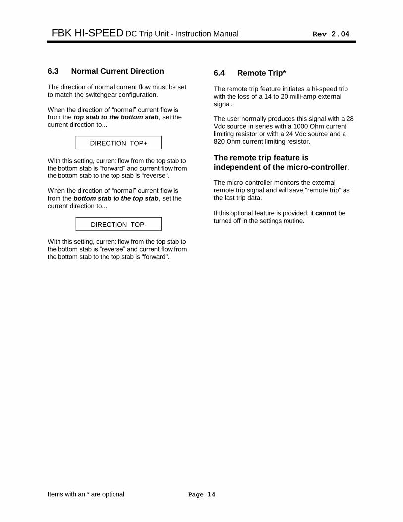
6.1 Hi-Speed Forward (FASTFOR) The FASTFOR pick-up setting ranges from 100% to 500% of the transducer rating in steps that depend on the rating of the transducer entered. An OFF setting is available if FASTREV* and/or R/R* is available and not OFF. The FASTFOR pick-up setting steps are 0.05 times the transducer rating. The steps for several typical transducer ratings are:
Transducer
Rating (amps)
FASTFOR
Pick-Up Steps
(amps)
500 25
800 40
1000 50
1200 60
1600 80
2000 100
3000 150
4000 200
6000 300
8000 400
10000 500
TABLE 1 When setting the FASTFOR trip function, the following is displayed…
FASTFOR PU XXXXXA
...where "XXXXX" represents the FASTFOR pick-up setting in amps.
Press and hold the up or down push button as required until the desired FASTFOR pick-up is displayed.
6.2 Hi-Speed Reverse* (FASTREV) The FASTREV pick-up setting ranges from 100% to 500% of the transducer rating in steps that depend on the rating of the transducer being used. The FASTREV pick-up setting steps are 0.05 times the transducer rating. An OFF setting is available if FASTFOR and/or R/R* is available and not OFF. The steps for several typical transducer ratings are given in Table 1. When setting the FASTREV trip function, the following is displayed…
FASTREV PU XXXXXA
...where "XXXXX" represents the FASTREV pick-up setting in amps.
Press and hold the up or down push button as required until the desired FASTREV pick-up is displayed.
FBK HI-SPEED DC Trip Unit - Instruction Manual Rev 2.04
Items with an * are optional Page 14
6.3 Normal Current Direction
The direction of normal current flow must be set to match the switchgear configuration. When the direction of “normal” current flow is from the top stab to the bottom stab, set the current direction to...
DIRECTION TOP+
With this setting, current flow from the top stab to the bottom stab is “forward” and current flow from the bottom stab to the top stab is "reverse". When the direction of “normal” current flow is from the bottom stab to the top stab, set the current direction to...
DIRECTION TOP-
With this setting, current flow from the top stab to the bottom stab is “reverse” and current flow from the bottom stab to the top stab is "forward".
6.4 Remote Trip* The remote trip feature initiates a hi-speed trip with the loss of a 14 to 20 milli-amp external signal. The user normally produces this signal with a 28 Vdc source in series with a 1000 Ohm current limiting resistor or with a 24 Vdc source and a 820 Ohm current limiting resistor.
The remote trip feature is
independent of the micro-controller.
The micro-controller monitors the external remote trip signal and will save "remote trip" as the last trip data.
If this optional feature is provided, it cannot be turned off in the settings routine.
FBK HI-SPEED DC Trip Unit - Instruction Manual Rev 2.04
Items with an * are optional Page 15
7.0 Non-Hi-Speed Trip Functions
7.1 Long Time Trip* The Long Time (LT) trip function provides "thermal" type overload protection. The LT trip function has a pick-up setting and a time delay setting. When setting the LT trip pick-up, the following is displayed...
LT PICK-UP OFF
or…
LT PICK-UP XXXXA
...where "XXXX" represents the LT pick-up setting in amps. The LT pick-up setting ranges from OFF and 40% to 100% of the transducer rating. This setting is adjustable in 5 amp steps (50 amp steps for transducers greater than 5000 amp).
Press and hold the up or down push button as required until OFF or the correct LT pick-up setting is displayed.
Press the enter push button to continue.
7.2 Long Time Delay* The following will be displayed if LT is on…
LT DELAY XX.XS
...where "XX.X" represents the LT Delay band. The LT Delay band is labeled by the number of
seconds to trip at 6 times the LT pick-up setting. The LT Delay setting ranges from 2.5 to 30 seconds in steps of 0.5 seconds. This provides 56 LT Delay bands.
Press and hold the up or down push button as required until the correct LT Delay setting is displayed.
Please note that the LT trip time is not a constant value, but is a function of the breaker current. For low currents the trip time is longer, and for higher currents the trip time is shorter. The trip time is only equal to the LT Delay setting when a current 6 times the LT pick-up setting is applied. See the time-current curves in Figure 8.
Press the enter push button to continue and the following will be displayed…
LT THERMAL ON
If the LT thermal function is desired, press the
enter push button to move to the next setting. If the LT thermal function is not desired, press
the down button to display…
LT THERMAL OFF
The LT trip function is designed to represent thermal heating. The LT thermal function is designed to mimic thermal cooling. If an overload current momentarily drops below the LT pick-up value... With LT thermal OFF, the LT trip register is
cleared and any new overload starts with zero in the trip timer register.
With LT thermal ON, the LT trip register is
slowly decremented when the current is below the LT pick-up and any new overload may start with a non-zero number in the trip timer register.
As shown in Figure 8, the LT trip curve is based on a square function. If the overload goes up by a factor of 2, the trip time goes down by a factor of 1/4.
FBK HI-SPEED DC Trip Unit - Instruction Manual Rev 2.04
Items with an * are optional Page 16
The LT trip curve can be restated as follows:
T = TBCLT
X²
Where: T = time to trip in seconds (center of the band)
X = current in multiples of the LT pick-up setting
TBCLT = the LT Time Band Constant = 36 X LT time band setting
**** NOTE **** The LT Time Band Constant (TBCLT) is by definition 36 times the LT Time Band Setting in seconds.
EXAMPLE: Transducer Rating 4000A LT pick-up 3000A LT time band 20.0S Overload Current 9000A TBCLT = 36 X LT Time Band Setting = 36 X 20.0 = 720 and X = overload current = 9000A = 3 LT Pick-Up 3000A therefore: trip time = T = TBCLT or 720 = 720 X² 3² 9 = 80 seconds
**** IN SUMMARY **** To calculate the LT trip time: 1) Calculate the LT Time Band
Constant (TBCLT) 2) Calculate "X" where X = overload current LT Pick-Up Setting 3) Solve the equation: trip time(sec) = TBCLT X2
7.3 Short Time Trip* The Short Time (ST) trip function provides a short delay in the trip time to coordinate with a downstream protective device. The ST trip function has a pick-up setting and a time delay setting. When setting the ST trip function, the following is displayed...
ST PICK-UP OFF
or…
ST PICK-UP XXXXA
...where "XXXX" represents the ST pick-up in amps. The ST pick-up setting ranges from OFF or 150% to 500% of the LT pick-up setting in 100 amp steps (1000 amp steps for transducers greater than 5000 amps). If the LT pick-up setting is OFF, then the ST pick-up range is based on the transducer rating.
Press and hold the up or down push button as required until the correct ST pick-up setting is displayed.
Press the enter push button to continue.
FBK HI-SPEED DC Trip Unit - Instruction Manual Rev 2.04
Items with an * are optional Page 17
7.4 Short Time Delay*
The ST delay curve is either a definite time or a combination of an I2T ramp and a definite time as shown in Figure 8. When setting the ST delay, the following is displayed...
ST DELAY .XXS
Where ".XX" represents the ST Delay. The ST delay settings are .07, .10, .15, .20 and .35 seconds.
Press and hold the up or down push button as required until the correct ST delay setting is displayed.
Press the enter push button to display…
ST I SQ T OFF
If the I²T ramp is not desired, press the enter push button to move to the next setting.
If the ST I²T ramp is desired, press the up push button. The following will be displayed:
ST I SQ T ON
With I2T off the ST trip time is a constant equal to the ST Time Band setting. With I2T on and for currents less than 10 X LT pick-up Setting, the ST trip time is determined by the following equation:
T = TBCST
X²
Where: T = time to trip in seconds (center of the band)
X = current in multiples of the LT pick-up
TBCST = the ST Time Band Constant
**** NOTE **** The ST Time Band Constant (TBCLT) = 12.6 for the .35S Time Band 7.2 for the .20S Time Band 5.4 for the .15S Time Band 3.6 for the .10S Time Band 2.52 for the .07S Time Band
EXAMPLE: Transducer Rating 6000A LT pick-up 5000A ST pick-up 10,000A ST time band .20S I²T ON Overload Current 15,000A TBCST = 7.2 and X = overload current = 15,000A = 3 LT Pick-Up 5000A therefore: trip time = T = TBCST or 7.2 = 7.2 X² 3² 9 = .80 seconds
**** IN SUMMARY **** To calculate the ST I2T trip time: 1) Determine the ST Time Band
Constant (TBCST) 2) Calculate "X" where X = overload current LT Pick-Up 3) Solve the equation: trip time(sec) = TBCST
X2
FBK HI-SPEED DC Trip Unit - Instruction Manual Rev 2.04
Items with an * are optional Page 18
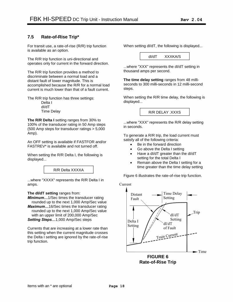
7.5 Rate-of-Rise Trip* For transit use, a rate-of-rise (R/R) trip function is available as an option. The R/R trip function is uni-directional and operates only for current in the forward direction. The R/R trip function provides a method to discriminate between a normal load and a distant fault of lower magnitude. This is accomplished because the R/R for a normal load current is much lower than that of a fault current. The R/R trip function has three settings: Delta I dI/dT Time Delay
The R/R Delta I setting ranges from 30% to 100% of the transducer rating in 50 Amp steps (500 Amp steps for transducer ratings > 5,000 Amp). An OFF setting is available if FASTFOR and/or FASTREV* is available and not turned off. When setting the R/R Delta I, the following is displayed...
R/R Delta XXXXA
...where "XXXX" represents the R/R Delta I in amps.
The dI/dT setting ranges from:
Minimum…1/Sec times the transducer rating rounded up to the next 1,000 Amp/Sec value Maximum…16/Sec times the transducer rating rounded up to the next 1,000 Amp/Sec value with an upper limit of 200,000 Amp/Sec Setting Steps…1,000 Amp/Sec steps Currents that are increasing at a lower rate than this setting when the current magnitude crosses the Delta I setting are ignored by the rate-of-rise trip function.
When setting dI/dT, the following is displayed...
dI/dT XXXKA/S
...where "XXX" represents the dI/dT setting in thousand amps per second.
The time delay setting ranges from 48 milli-seconds to 300 milli-seconds in 12 milli-second steps. When setting the R/R time delay, the following is displayed...
R/R DELAY .XXXS
...where "XXX" represents the R/R delay setting in seconds. To generate a R/R trip, the load current must satisfy all of the following criteria:
Be in the forward direction
Go above the Delta I setting
Have a dI/dT greater than the dI/dT setting for the total Delta I
Remain above the Delta I setting for a time greater than the time delay setting
Figure 6 illustrates the rate-of-rise trip function.
Train Current
Delta ISetting
Time DelaySetting
DistantFault
Trip
SettingdI/dT
dI/dTof Fault
FIGURE 6
Rate-of-Rise Trip
FBK HI-SPEED DC Trip Unit - Instruction Manual Rev 2.04
Items with an * are optional Page 19
8.0 Loss of Control Voltage* (UV) If the loss of control voltage (UV) function is on, a trip will be initiated with a drop in control voltage. When setting the UV trip, the following is displayed...
UV TRIP ON
or…
UV TRIP OFF
Use the up or down push buttons to change the setting if desired. An under voltage trip* (UV) trip will not operate the momentary alarm contact or the lockout contact*.
9.0 Settings
9.1 Reviewing Last Trip Data The trip unit last trip data and settings can be easily reviewed at any time.
On the Hi-Speed trip unit push the menu button to enter the last trip data/settings review program.
Protection will still be provided while in the
last trip data/settings review program.
Continue to push the menu button to step through the last trip data, the trip log and the settings.
On the remote display* push the review button to enter the last trip data/settings review program.
Continue to push the review button to step through the last trip data, the trip log and the settings. The trip unit saves the data for the last 3 trip events, new trip data is written over the last 3 trip events if necessary. The latest trip is identified as “LAST TRIP”. The second latest trip is identified as “LAST TRIP-1”. The third latest trip is identified as “LAST TRIP-2”. If no trip events have occurred since the last trip data/trip log was cleared, “NO LAST TRIP” is displayed. The last trip data consists of the type of trip (i.e., LT, ST, FASTFOR, FASTREV, R/R, REMOTE, TEST or UV as applicable) and the associated DC current. For a FASTFOR or FASTREV trip, the DC current at the time of trip is not displayed because the trip occurred while the current was ramping up to some higher value not known to the trip unit.
If the menu or review button is not pushed for 30 seconds, the LCD will resume its normal display.
FBK HI-SPEED DC Trip Unit - Instruction Manual Rev 2.04
Items with an * are optional Page 20
9.2 Reviewing Settings
Continue to push the menu or review button to step thru the last trip data and the trip log and then to review the settings.
Continued pushing of the menu or review button will step through the settings.
If the menu or review button is not pushed for 30 seconds, the LCD will resume its normal display.
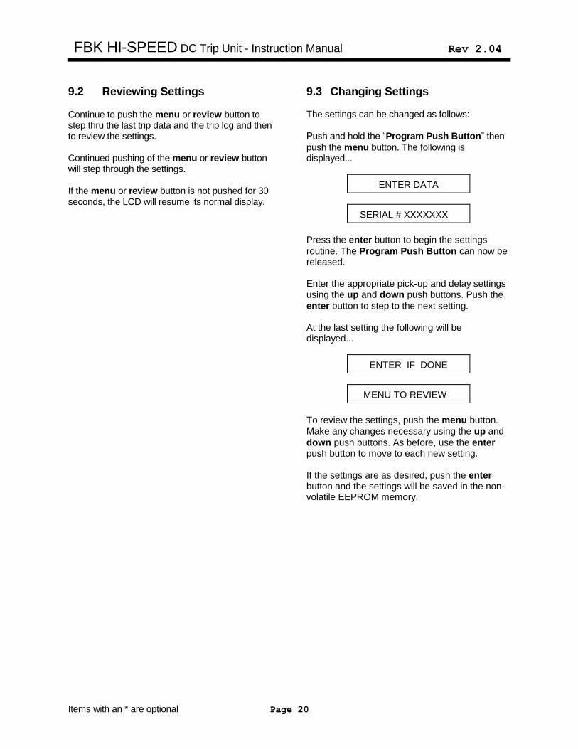
9.3 Changing Settings The settings can be changed as follows:
Push and hold the “Program Push Button” then
push the menu button. The following is displayed...
ENTER DATA
SERIAL # XXXXXXX
Press the enter button to begin the settings
routine. The Program Push Button can now be released. Enter the appropriate pick-up and delay settings
using the up and down push buttons. Push the
enter button to step to the next setting. At the last setting the following will be displayed...
ENTER IF DONE
MENU TO REVIEW
To review the settings, push the menu button.
Make any changes necessary using the up and
down push buttons. As before, use the enter push button to move to each new setting.
If the settings are as desired, push the enter button and the settings will be saved in the non-volatile EEPROM memory.
FBK HI-SPEED DC Trip Unit - Instruction Manual Rev 2.04
Items with an * are optional Page 21
9.4 Transducer Rating Security
Feature
The Hi-Speed trip unit has a security feature to help prevent accidentally changing the programmed transducer rating.
The transducer rating programmed in the trip
unit must match the actual calibrated
transducer rating as described in Section
10.2. The transducer rating setting must be changed in the trip unit if:
The current transducer will be recalibrated to a different value.
or…
A current transducer with a different calibrated value will be installed on the breaker.
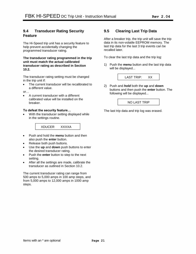
To defeat the security feature…
With the transducer setting displayed while in the settings routine.
XDUCER XXXXA
Push and hold the menu button and then
also push the enter button.
Release both push buttons.
Use the up and down push buttons to enter the desired transducer rating.
Push the enter button to step to the next setting.
After all the settings are made, calibrate the transducer as outlined in Section 10.2.
The current transducer rating can range from 500 amps to 5,000 amps in 100 amp steps, and from 5,000 amps to 12,000 amps in 1000 amp steps.
9.5 Clearing Last Trip Data After a breaker trip, the trip unit will save the trip data in its non-volatile EEPROM memory. The last trip data for the last 3 trip events can be recalled later. To clear the last trip data and the trip log:
1) Push the menu button and the last trip data will be displayed...
LAST TRIP: XX
2) Push and hold both the up and down
buttons and then push the enter button. The following will be displayed...
NO LAST TRIP
The last trip data and trip log was erased.
FBK HI-SPEED DC Trip Unit - Instruction Manual Rev 2.04
Items with an * are optional Page 22
10.0 Testing & Calibration
10.1 Enter Desired Settings With control power applied to the trip unit, enter the desired settings as previously described.
10.2 Transducer Calibration The transducer is factory calibrated and is currently available in the following ratings: 4000 Amp Frame: 500 Amp 1600 Amp 2500 Amp 4000 Amp 6000 Amp Frame: 500 Amp 4000 Amp 6000 Amp 8000 Amp, 2-Pole Frame: 4000 Amp 10,000 Amp, 2-Pole Frame: 5000 Amp 12,000 Amp, 2-Pole Frame 6000 Amp
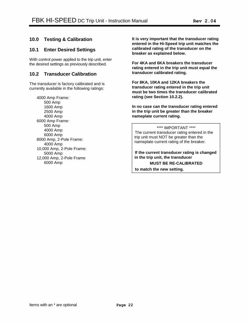
It is very important that the transducer rating
entered in the Hi-Speed trip unit matches the
calibrated rating of the transducer on the
breaker as explained below.
For 4KA and 6KA breakers the transducer
rating entered in the trip unit must equal the
transducer calibrated rating.
For 8KA, 10KA and 12KA breakers the
transducer rating entered in the trip unit
must be two times the transducer calibrated
rating (see Section 10.2.2).
In no case can the transducer rating entered
in the trip unit be greater than the breaker
nameplate current rating.
**** IMPORTANT **** The current transducer rating entered in the trip unit must NOT be greater than the nameplate current rating of the breaker.
If the current transducer rating is changed
in the trip unit, the transducer
MUST BE RE-CALIBRATED
to match the new setting.
FBK HI-SPEED DC Trip Unit - Instruction Manual Rev 2.04
Items with an * are optional Page 23
10.3 Verify Pick-Up & Trip Times A DC high current test set can be used to primary injection test the pick-up and time delays of the various trip functions. A DC test set with very low ripple is recommended as described in Section 10.2. 1. Verify proper calibration in the forward
direction by testing at several other values of current. The minimum suggested test values are at 50%, 100% and 400% of the programmed transducer rating.
2. Reverse the current direction and verify
proper calibration in the reverse direction by testing at several values of current. The minimum suggested test values are 50%, 100% and 400% of the transducer rating.
**** IMPORTANT **** For the 8KA, 10KA & 12KA, 2-pole breakers,
the Hi-Speed trip unit will display two times the current injected through the breaker pole with the transducer installed.
The R/R* function cannot be completely tested with a normal high current DC test set. A rough test can be performed as follows:
No Trip Test...Slowly increase the test current above the R/R Delta I setting.
A R/R trip should not occur.
Trip Test...Adjust the test set controls for a test current greater than the R/R Delta I setting. Start the test current so that a "step" function is created. A R/R trip should occur.
10.4 Forced Trip A forced trip is a test trip can be initiated from the front of the trip unit. Whenever: “LOW CURRENT” or “CURRENT XXXXX A” or “REVERSE XXXXX A” is displayed
Push and hold the Program Settings button
Simultaneously push both the up and down buttons and the trip unit will initiate a forced trip
Release all buttons
The last trip data will indicate that a forced trip occurred
10.5 Erase Last Trip Data After completing the primary injection test, it is important to erase the last trip data from the memory of the trip unit.
**** IMPORTANT **** Erase the last trip data from the memory of the trip unit after completing the primary injection tests.
See section 9.5 for clearing the last trip data.
FBK HI-SPEED DC Trip Unit - Instruction Manual Rev 2.04
Items with an * are optional Page 24
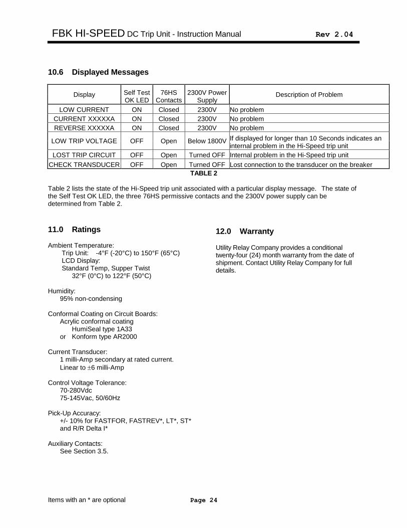
10.6 Displayed Messages
Display Self Test OK LED
76HS Contacts
2300V Power Supply
Description of Problem
LOW CURRENT ON Closed 2300V No problem
CURRENT XXXXXA ON Closed 2300V No problem
REVERSE XXXXXA ON Closed 2300V No problem
LOW TRIP VOLTAGE OFF Open Below 1800V If displayed for longer than 10 Seconds indicates an internal problem in the Hi-Speed trip unit
LOST TRIP CIRCUIT OFF Open Turned OFF Internal problem in the Hi-Speed trip unit
CHECK TRANSDUCER OFF Open Turned OFF Lost connection to the transducer on the breaker
TABLE 2 Table 2 lists the state of the Hi-Speed trip unit associated with a particular display message. The state of the Self Test OK LED, the three 76HS permissive contacts and the 2300V power supply can be determined from Table 2.
11.0 Ratings Ambient Temperature: Trip Unit: -4°F (-20°C) to 150°F (65°C) LCD Display: Standard Temp, Supper Twist 32°F (0°C) to 122°F (50°C) Humidity: 95% non-condensing Conformal Coating on Circuit Boards: Acrylic conformal coating HumiSeal type 1A33 or Konform type AR2000 Current Transducer: 1 milli-Amp secondary at rated current.
Linear to 6 milli-Amp Control Voltage Tolerance: 70-280Vdc 75-145Vac, 50/60Hz Pick-Up Accuracy:
+/- 10% for FASTFOR, FASTREV*, LT*, ST* and R/R Delta I*
Auxiliary Contacts: See Section 3.5.
12.0 Warranty Utility Relay Company provides a conditional twenty-four (24) month warranty from the date of shipment. Contact Utility Relay Company for full details.
FBK HI-SPEED DC Trip Unit - Instruction Manual Rev 2.04
Page 25
A
B+- 250Vdc or 120Vac 50/60Hz
D
K
Spare 2
X-CoilF
E
C
J
Spare 1
76HS1
76HS2
76HS3
L
Lockout*
V
S
Momentary Alarm
R
U
Control power 125Vdc or
Trip on loss of 20mA-25mARemote Trip*
I/O Circuits
ControlCable
Shielded Transducer Cable
Hall EffectCurrent Transducer
Logic CircuitMicrocontroller
Power & Signal
Power SupplyHigh Voltage
Measurement& Control
Capacitor Trip Circuit
C
A
B
ImpulseTrip Coil
+ Trip
- Trip
Bi-directional
Hi-Speed Trip Unit
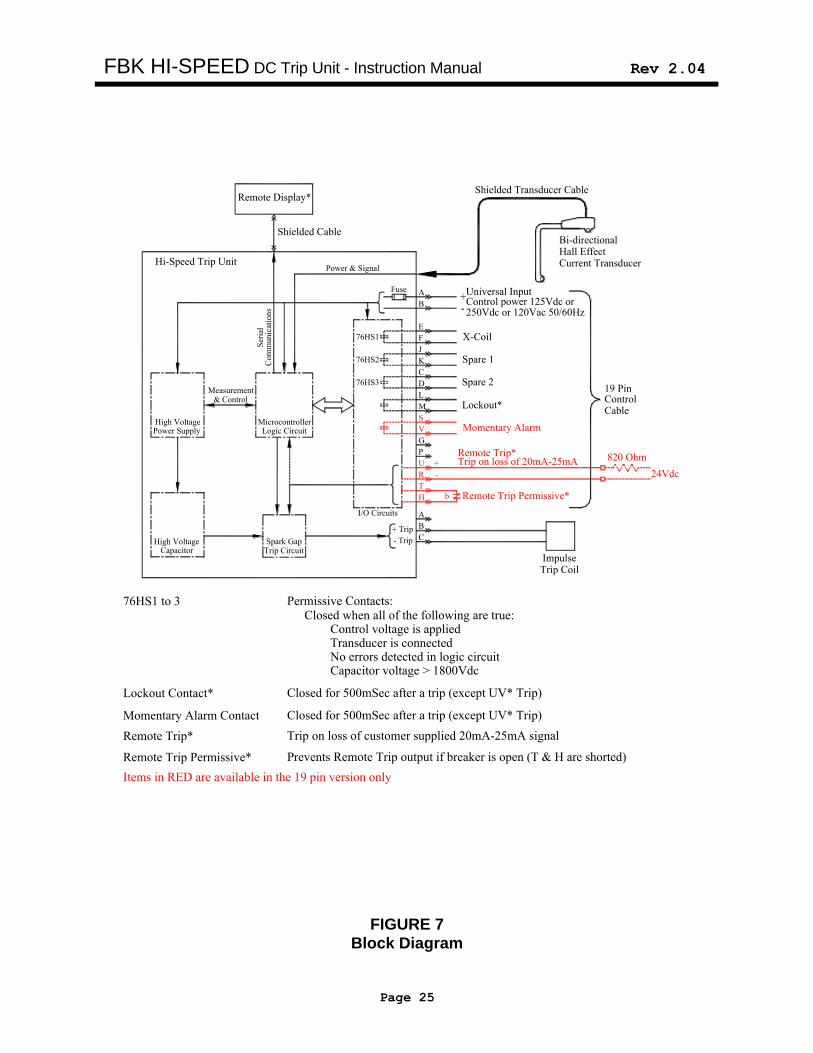
76HS1 to 3
Lockout Contact*
Momentary Alarm Contact
Closed when all of the following are true:Control voltage is appliedTransducer is connectedNo errors detected in logic circuitCapacitor voltage > 1800Vdc
Closed for 500mSec after a trip (except UV* Trip)
Closed for 500mSec after a trip (except UV* Trip)
19 Pin
High Voltage
H
T
Remote Trip Permissive*
820 Ohm
24Vdc
b
Trip on loss of customer supplied 20mA-25mA signalRemote Trip*
Prevents Remote Trip output if breaker is open (T & H are shorted)Remote Trip Permissive*
+
-
Fuse Universal Input
G
Permissive Contacts:
Remote Display*
Ser
ial
Com
munic
atio
ns
Spark Gap
Shielded Cable
Items in RED are available in the 19 pin version only
M
P
FIGURE 7
Block Diagram
FBK HI-SPEED DC Trip Unit - Instruction Manual Rev 2.04
Page 26
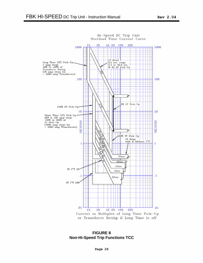
FIGURE 8
Non-Hi-Speed Trip Functions TCC


![Cesar, hi - Augsburg Universityweb.augsburg.edu/global/CubaTripLeaderGuide2015.docx · Web viewCGE CUBA TRIP LEADER’S GUIDE [as of May 2015] Trip leader responsibilities in Cuba](https://img.pdfslide.net/doc/110x75/5a6e9f587f8b9ae6638b5181/cesar-hi-augsburg-universitywebaugsburgeduglobalcubatripleaderguide2015docxdoc.jpg)