Embed Size (px)
Citation preview

TP-301R-02 January 17, 2007
U.S. DEPARTMENT OF TRANSPORTATION
NATIONAL HIGHWAY TRAFFIC SAFETY ADMINISTRATION
LABORATORY TEST PROCEDURE
FOR
FMVSS 301R
Fuel System Integrity – Rear Impact
ENFORCEMENT Office of Vehicle Safety Compliance
Room 6111, NVS-220 400 Seventh Street, SW Washington, DC 20590

COMPLIANCE TEST PROCEDURE CHANGE CONTROL
FMVSS No: 301R Title: Fuel System Integrity – Rear Impact
Approval (Initials/Date) Issue Date Test Procedure Revision
Number Revision
Description Test Engr.
Division Chief
Spec. Asst.
Office Director
TP-301R-00 No Revision
TP-301R-01 Clarify Stoddard Quality Requirement
TP-301R-02 Correct MDB weight
TP-301R-03
TP-301R-04
TP-301R-05
TP-301R-06
TP-301R-07
TP-301R-08
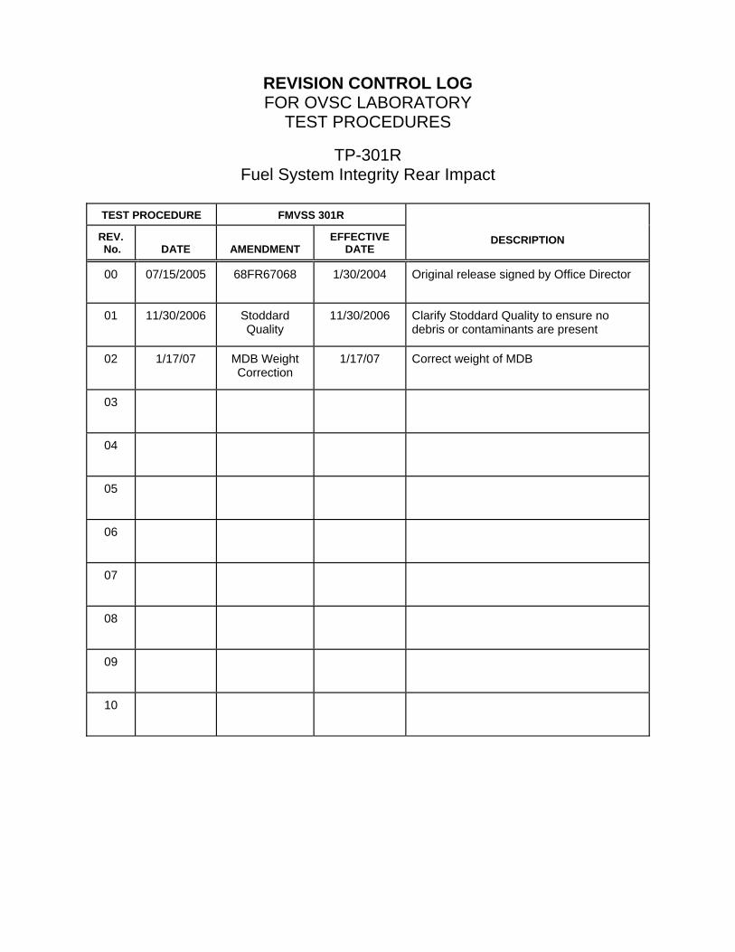
REVISION CONTROL LOG FOR OVSC LABORATORY
TEST PROCEDURES
TP-301R Fuel System Integrity Rear Impact
TEST PROCEDURE FMVSS 301R
REV. No.
DATE
AMENDMENT
EFFECTIVE DATE
DESCRIPTION
00 07/15/2005 68FR67068 1/30/2004 Original release signed by Office Director
01 11/30/2006 Stoddard Quality
11/30/2006 Clarify Stoddard Quality to ensure no debris or contaminants are present
02 1/17/07 MDB Weight Correction
1/17/07 Correct weight of MDB
03
04
05
06
07
08
09
10
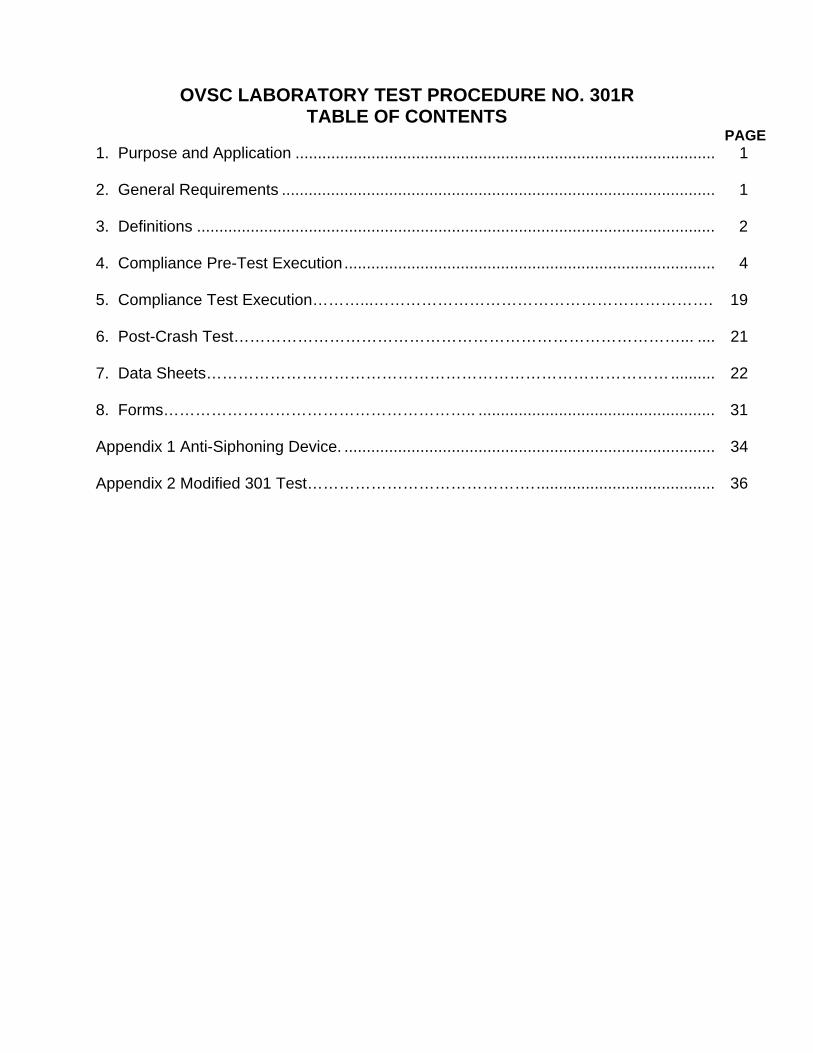
OVSC LABORATORY TEST PROCEDURE NO. 301R TABLE OF CONTENTS
PAGE 1. Purpose and Application .............................................................................................. 1 2. General Requirements ................................................................................................. 1 3. Definitions .................................................................................................................... 2 4. Compliance Pre-Test Execution................................................................................... 4 5. Compliance Test Execution………...………………………………………………………. 19 6. Post-Crash Test…………………………………………………………………………... .... 21 7. Data Sheets…………………………………………………………………………….......... 22 8. Forms………………………………………………….. ..................................................... 31 Appendix 1 Anti-Siphoning Device. ................................................................................... 34 Appendix 2 Modified 301 Test……………………………………......................................... 36

1
1.0 Purpose and Application The Office of Vehicle Safety Compliance (OVSC) is providing this Laboratory Test Procedure (TP) for the use of its contractor laboratories. The purpose of this TP is to provide guidelines for obtaining data in OVSC compliance testing programs and a uniform data recording format. This TP does not limit a laboratory’s testing methods to the procedures specified in the TP or specific brands of testing equipment. However, any deviation from the TP’s testing procedures or recommended testing equipment must be approved by the Contracting Officer’s Technical Representative (COTR). The data obtained in an OVSC compliance test are used to determine if the test specimen, a specific vehicle or item of motor vehicle equipment, meets the requirements specified in the TP. In some cases the TP does not include all of the various minimum performance requirements that are part of the associated Federal Motor Vehicle Safety Standard (FMVSS). Recognizing applicable test tolerances, the TP may specify test conditions that are less severe than the minimum requirements specified in the FMVSS. If a contract laboratory views any part of the TP to be in conflict with the associated FMVSS or observes deficiencies in the TP, the contract laboratory shall advise the COTR and resolve the discrepancy prior to the start or resumption of compliance testing. Legal Note: The OVSC Test Procedures are prepared for the limited purpose of use by independent laboratories under contract to conduct compliance tests for the OVSC. The TP’s are not rules, regulations or NHTSA interpretations regarding the FMVSS. The TP’s are not intended to limit the requirements of the applicable FMVSS(s). In addition the TP’s may be modified by the OVSC at any time without notice, and the COTR may direct or authorize contractors to deviate from these procedures, as long as the tests are performed in a manner consistent with the FMVSS itself and within the scope of the contract. TP’s may not be relied upon to create any right or benefit in any person. Therefore, compliance of a vehicle or item of motor vehicle equipment is not guaranteed if the manufacturer limits its certification tests to those described in the TP. 2.0 General Requirements FUEL SPILLAGE — BARRIER CRASH
Fuel spillage resulting from the moving barrier crash test shall not exceed 28 g from impact until motion of the vehicle has ceased, and shall not exceed a total of 142 g in the 5- minute period following cessation of motion. For the subsequent 25-minute period, fuel spillage during any 1 minute interval shall not exceed 28 g. FUEL SPILLAGE — ROLLOVER Fuel spillage during a rollover test, from the onset of rotational motion, shall not exceed a total of 142 g for the first 5 minutes of testing at each successive 90° increment. For the remaining testing period, at each successive 90° increment, fuel spillage during any 1-minute interval shall not exceed 28 g.

2
3.0 Definitions DESIGNATED SEATING CAPACITY (DSC) Number of designated seating positions (DSPs) provided in the vehicle. DESIGNATED SEATING POSITION (DSP) Any plan view location capable of accommodating a person at least as large as a 5th- percentile adult female, if the overall seat configuration and design and vehicle design is such that the position is likely to be used as a seating position while the vehicle is in motion, except for auxiliary seating accommodations such as temporary or folding jump seats. Any bench or split-bench seat in a passenger car, truck or multipurpose passenger vehicle (MPV) with a GVWR less than 4,536 kg, having greater than 1270 mm of hip room (measured in accordance with SAE J1100a) shall have not less than 3 designated seating positions, unless the seat design or vehicle design is such that the center position cannot be used for seating. FUEL SPILLAGE The fall, flow, or run of fuel from the vehicle but does not include wetness resulting from capillary action. GROSS AXLE WEIGHT RATING (GAWR) Value specified by the vehicle manufacturer as the load-carrying capacity of a single axle system, as measured at the tire-ground interfaces. GROSS VEHICLE WEIGHT RATING (GVWR) Value specified by the manufacturer as the loaded weight of a single vehicle. LONGITUDINAL OR LONGITUDINALLY Parallel to the longitudinal centerline of the vehicle. MULTIPURPOSE PASSENGER VEHICLE (MPV) Motor vehicle with motive power, except a trailer, designed to carry 10 persons or less which is constructed either on a truck chassis or with special features for occasional off- road operation.
3
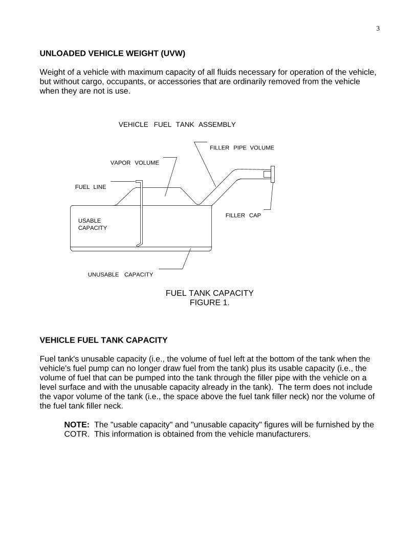
UNLOADED VEHICLE WEIGHT (UVW) Weight of a vehicle with maximum capacity of all fluids necessary for operation of the vehicle, but without cargo, occupants, or accessories that are ordinarily removed from the vehicle when they are not is use.
VAPOR VOLUME
UNUSABLE CAPACITY
FILLER PIPE VOLUME
FILLER CAP
VEHICLE FUEL TANK ASSEMBLY
FUEL LINE
USABLECAPACITY
FUEL TANK CAPACITY FIGURE 1.
VEHICLE FUEL TANK CAPACITY Fuel tank's unusable capacity (i.e., the volume of fuel left at the bottom of the tank when the vehicle's fuel pump can no longer draw fuel from the tank) plus its usable capacity (i.e., the volume of fuel that can be pumped into the tank through the filler pipe with the vehicle on a level surface and with the unusable capacity already in the tank). The term does not include the vapor volume of the tank (i.e., the space above the fuel tank filler neck) nor the volume of the fuel tank filler neck.
NOTE: The "usable capacity" and "unusable capacity" figures will be furnished by the COTR. This information is obtained from the vehicle manufacturers.
4
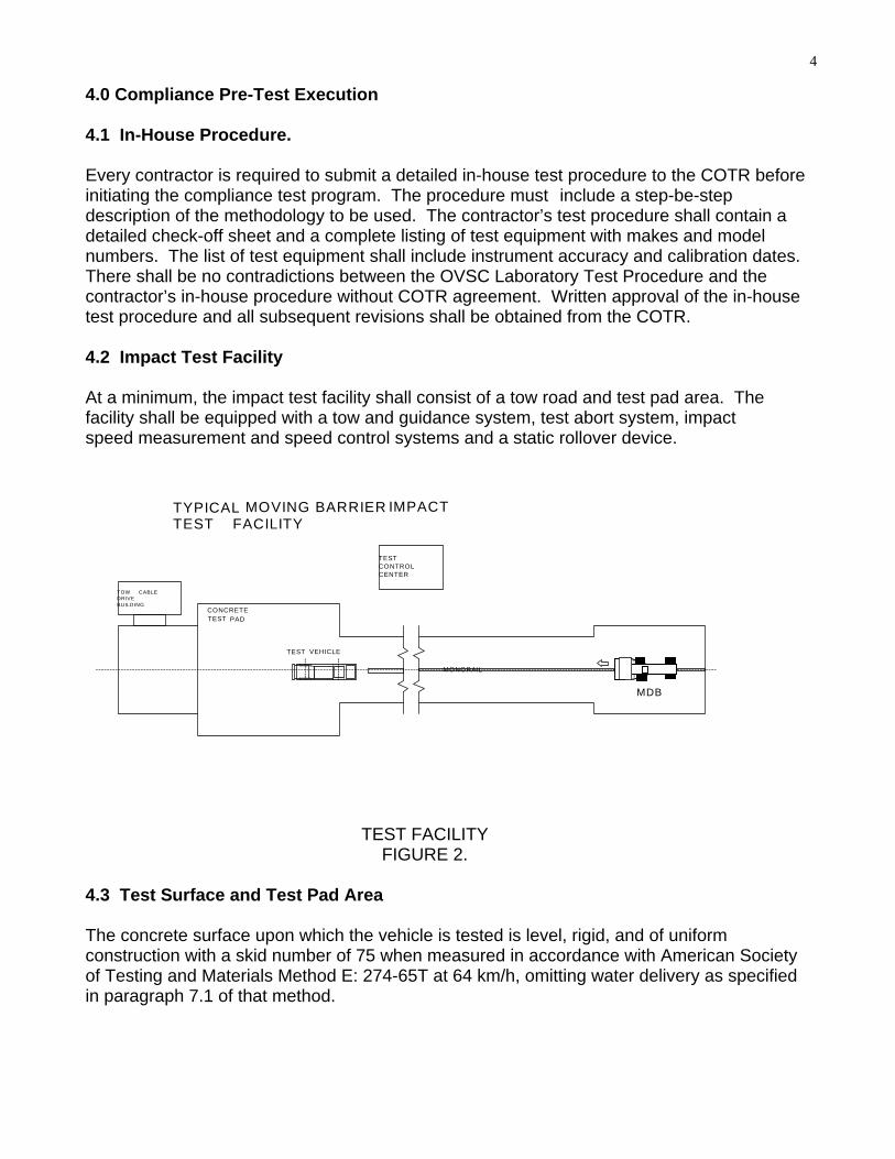
4.0 Compliance Pre-Test Execution 4.1 In-House Procedure. Every contractor is required to submit a detailed in-house test procedure to the COTR before initiating the compliance test program. The procedure must include a step-be-step description of the methodology to be used. The contractor’s test procedure shall contain a detailed check-off sheet and a complete listing of test equipment with makes and model numbers. The list of test equipment shall include instrument accuracy and calibration dates. There shall be no contradictions between the OVSC Laboratory Test Procedure and the contractor’s in-house procedure without COTR agreement. Written approval of the in-house test procedure and all subsequent revisions shall be obtained from the COTR. 4.2 Impact Test Facility At a minimum, the impact test facility shall consist of a tow road and test pad area. The facility shall be equipped with a tow and guidance system, test abort system, impact speed measurement and speed control systems and a static rollover device.
TYPICAL MOVING BARRIER IMPACT TEST FACILITY
MONORAIL
TEST VEHICLE
TESTCONTROLCENTER
TOW CABLE DRIVE BUILDING
CONCRETE TEST PAD
MDB
TEST FACILITY
FIGURE 2. 4.3 Test Surface and Test Pad Area The concrete surface upon which the vehicle is tested is level, rigid, and of uniform construction with a skid number of 75 when measured in accordance with American Society of Testing and Materials Method E: 274-65T at 64 km/h, omitting water delivery as specified in paragraph 7.1 of that method.

5
4.4 Tow Road The tow road surface shall be straight, level, smooth and of uniform construction. The tow road shall be of sufficient length to allow constant velocity of the moving barrier (free wheeling prior to impact). 4.5 Tow and Guidance System The tow and guidance system shall be capable of ensuring that the moving barrier impact at the proper angle and within 0.8 km/hr. The moving barrier shall be continuously towed until it reaches 610 mm to 152 mm from impact. The tow cable attachment device shall release from the tow cable within the tolerance window. The velocity measurement shall be taken after cable release. 4.6 Test Abort System Test vehicles and the moving barrier shall be equipped with onboard brake abort systems. The target vehicle and the moving barrier brake systems shall not be activated until after the final vehicle/barrier separation has occurred unless the vehicle rear wheels are jammed by deformed sheet metal and the vehicle remains against the moving barrier's face throughout the braking process. Moving barrier brakes shall be applied in advance of test vehicle brakes in order to preclude secondary impacts. The OVSC recommends the use of redundant brake abort systems. 4.7 Impact Speed Measurement System. Moving barrier impact speed or velocity shall be measured by 2 timing devices (photocells, break wires, laser beams, etc.) located within 1.5 meters of the impact plane. Both timing devices shall be accurate within plus or minus 0.08 km/h and shall be calibrated by an instrument traceable to the National Institute of Standards and Technology. The impact speed shall be permanently recorded. A third timing device, if the laboratory desires, may be placed at a sufficient distance from the impact plane for monitoring the speed of the test vehicle or moving barrier and permit a test abort if necessary. 4.8 Moving Barrier Guidance A guidance system is required to assure that the moving barrier impacts the target vehicle at the proper angle. Normally a monorail, which extends along the center of the tow road, is used for lateral guidance with a small dolly or guide shoe "riding" on the monorail and engaging the drive cable through a set of jaws, which grip the cable. The guide shoe is normally released from the monorail and the moving barrier free wheels into the barrier face or target vehicle. The release of the barrier may take place between 152 and 610 mm from the impacted side of the test vehicle.
6
NOTE: The test vehicle shall be placed on a concrete test surface. Steel grating is not allowed. MOVING DEFORMABLE BARRIER (MDB): For vehicles certified after September 1, 2006, or for early phase-in vehicles certified with the MDB, the contractor shall provide a moving deformable barrier as specified in FMVSS 214D (see Figure 3) with exceptions to barrier height. The contractor is responsible for certifying that the barrier meets all the requirements prior to the start of testing. A summary of MDB and honeycomb face specifications are provided as follows: A. Total weight of MDB with impact face shall be 1,361 ± 4.5 kg (configured MDB weight
of 1,367.6 kg stated in P587.6(c). B. Overall length of MDB with impact face = 4,115 mm ± 25 mm C. Overall length of MDB excluding impact face = 3,632 mm (includes 50.8 mm thick
mounting block) D. Overall width of framework carriage = 1,251 mm E. Tracking width (centerline to centerline of front or rear wheels) = 1,880 mm F. Wheelbase for framework carriage = 2,591 mm ± 25 mm G. Inertial properties of the MDB (with two cameras and camera mounts and a light trap
vane and ballast reduced); the center of gravity (CG) is as follows: X = (1,123 ± 25 ) mm rear of front axle Y = (7.6 ± 25) mm left of longitudinal centerline Z = (450 ± 25) mm from ground Moments of inertia (tolerance 5% for testing purposes) are as follows: Pitch = 2,263 kg-m2
Roll = 508 kg-m2
Yaw = 2,572 kg-m2

7
H. Shape of honeycomb impact face
Width =1,676 mm ± 6 mm Height = 559 mm ± 6 mm Ground Clearance = 229 mm ± 3 mm Depth at Bumper Height = 483 mm ± 6 mm Depth at upper impact face = 381 mm ± 6 mm I. Force-deflection properties (crush strength) for honeycomb impact face shall be 310
kpa ± 17 kpa and 1,690 kpa ± 103 kpa for the bumper. These properties shall be demonstrated to the Compliance Engineer prior to the start of testing.

8
HONEYCOMB
A
A
FRONT VIEW
GROUND
483
280 SECTION A-A
381 483
51
559 788
229
BUMPER
1676
4115
3,632 2,591
1,251
1,880
BALLAST
BARRIER FACE
NHTSA BARRIER FACE
INSTRUMENTATION
BALLAST
TOP VIEW
SIDE VIEW
203 Do Not Bond This Surface Only
Alum. Honeycomb Bumper, 1690 ± 103 kpa crush t th 0.8 mm Alum. Face, 26 ksi 5052- H34
ALL DIMENSIONS IN MILLIMETERS
NHTSA MOVING DEFORMABLE BARRIER FIGURE 3.

9
4.9 Static Rollover Device The rollover device shall be capable of rotating the impacted test vehicle about its longitudinal axis with the axis kept horizontal, to each successive increment of 90°, 180°, and 270° at a uniform rate, with 90° of rotation taking place in any time interval from 1 to 3 minutes and holding in position up to an additional 5 minutes. The rollover device shall be of sufficient size to accommodate all vehicles to which the standard applies.
4.10 Weighing Scales The scales used to weigh the test vehicle shall be accurate to within 0.1% of weight of vehicle. 4.11 Pretest Test Procedure. The contractor shall perform the following steps prior to conducting a crash test.
A. Measure and Prepare Data Sheet 1, Test Vehicle Specifications B. Measure and Prepare Data Sheet 2, Pre-Test Data C. Prepare and Measure Moving Barrier D. Prepare Data Sheet 3, Moving Barrier Data E. Paint the Underbody F. Properly Fill Tank, Ballast, Prepare Test Vehicle G. Position Dummies and Measure Seating Position (if applicable) H. Position High Speed Cameras I. Ensure all Data Acquisition Systems Are in Working Order
4.11.1 Test Vehicle Preparation. The following shall be performed prior to conducting any crash test. 4.11.1.1 Vehicle Test Weight as Delivered (UVW) After the test vehicle is received, add fluids to levels specified in the manufacture’s data sheet and then weigh the vehicle. Record on data sheet as "Unloaded Vehicle Weight" (UVW). 4.11.1.2 Target Test Weight (TTW) Calculate the vehicle’s Rated Cargo and Luggage Weight (RCLW). RCLW is determined by using the information contained on the vehicle’s tire placard required by FMVSS 110, “Tire Selection and Rims,” and usually affixed to the vehicle’s left B post. Standard 110 requires that the Vehicle Capacity Weight (VCW) and Designated Seating Capacity (DSC) or number of occupants be recorded on the tire placard. Calculate and record RCLW as follows: RCLW = VCW - (DSC X 68 kg. per occupant) If Standard 110 information is not available for a MPV, light truck or bus, use the following calculation:

10
RCLW = GVWR - UVW - (68 kg x DSC), where DSC is obtained by counting the total number of seat belt assemblies throughout the vehicle
Calculate and record the Target Test Weight (TTW) as follows: TTW = UVW + RCLW + (2 dummies x 74 kg. /dummy) MPV’s, light trucks and buses with a MAXIMUM GVWR 4,536 kg are loaded to UVW , plus 136 kg or its RCLW, whichever is LESS, secured to the vehicle, plus a Part 572 dummy at each front outboard seating position.
4.11.1.3 As Tested Weight (ACTUAL TEST WEIGHT) Drain the fuel system and operate the engine until the fuel system is dry. Slowly refill the entire fuel system (rotate engine) with Stoddard solvent which has been dyed purple, having the physical and chemical properties of Type 1 solvent or cleaning fluid, Table 1, ASTM Standard D484-71, “Standard Specifications for Hydrocarbon Dry-cleaning Solvents” until, not less than 92 percent and not more than 94 percent, of the vehicle manufacturer's stated “usable capacity” is reached. This volume will be furnished by the COTR. The Stoddard solvent must be free of debris while being introduced into the fuel system (see Note 1). Drain all other fluids from the test vehicle with the exception of brake fluid if required for abort system, so that Stoddard solvent leakage from the fuel system will be evident. Just prior to the test, operate the engine (“crank”), to assure that Stoddard solvent is present throughout the entire fuel system.
It is permissible to cut small holes in coolant hose and transmission torque converters to assure that all fluid other than Stoddard solvent has been removed from the vehicle.
NOTE 1: The contractor MUST maintain the integrity (debris-free) of the Stoddard when introduced into the vehicle.
Debris: The Stoddard solvent shall be considered debris-free, only if upon filtering with a 10 micron filter, no solid debris is retained on the filter media or in any conduit, container or vessel upstream from the filter paper (e.g. debris is not allowed to be present in the funnel, pump, or container.).
NOTE 2: The removal process must prevent solvent contact with substances which
may be soluble in the Stoddard solvent. (i.e. undercoating, paints used for identifying under-vehicle components, etc.)
NOTE 3: The solvent used for NHTSA testing must be designated for only NHTSA
testing. Load the vehicle with the required test dummies and necessary on-board test equipment (including all instrumentation, cameras, lighting, etc.) and then add ballast, if necessary, to

11
achieve the Target Test Weight. The load is distributed so that the weight on each axle as measured at the tire-ground interfaces is in proportion to its GAWR. The Actual Test Weight (ATW) shall have the following boundaries (using the same scales to reduce precision variability with change of equipment); (TTW - 10 kg.) ≤ ATW < (TTW – 5 kg.) If the ATW exceeds or equals TTW, the contractor shall notify the COTR to discuss the possible removal of vehicle components or instrumentation, which would decrease the weight.
UNDER NO CIRCUMSTANCES SHALL THE ACTUAL TEST WEIGHT (ATW) BE GREATER THAN THE TARGET TEST WEIGHT (TTW).
4.11.1.4 Vehicle Attitude Measurements If the test vehicle has an AUTO-LEVELING SYSTEM the system shall be powered (ignition "on") when attitude measurements are made. 4.11.1.4.1 As Delivered Attitude With the test vehicle in the “As Delivered” (full fluids) condition, position the vehicle on a level surface and inflate all tires to the manufacturer's specifications as listed on the vehicle's tire information label or placard. Measure the distance between each of the four tire-to-ground interfaces and a pre-selected reference point on the test vehicle’s body, directly above each wheel opening. Record on data sheet as the “As Delivered” attitude. 4.11.1.4.2 As Tested Attitude With the test vehicle in the “As Tested” condition, position the vehicle on a level surface and inflate all tires to the manufacturer's specifications as listed on the vehicle's tire information label or placard. Measure the distance between each of the four tire-ground interfaces and the pre-selected reference point (same points used for “As Delivered”) on the test vehicle’s body directly above each wheel opening. Record on data sheet as the “As Tested” attitude. 4.11.1.4.3 Underbody Paint
The underbody of the test vehicle shall be painted flat white and the various fuel system components such as the fuel tank, filler pipe, supply line, return line, etc., painted in contrasting colors such as red, green, orange, etc., to aid photography. Identification placards shall be used as previously noted. 4.11.1.5 Front Seat Cushion Adjustment Adjustable front seats are in the adjustment position MIDWAY between the forwardmost and rearmost positions, and if separately adjustable in a vertical direction, are at the LOWEST position. If an adjustment position does not exist midway between the forwardmost and

12
rearmost positions, the closest adjustment position to the REAR of the midpoint is used. Record the extremes of seat cushion adjuster fore and aft travel and the midpoint on the vehicle's rocker panel or side sill cover plate using a black marker after placing a vertical reference line on the outboard side of the front seat(s). 4.11.1.6 Front Seat back Adjustment Place adjustable front seat backs in the vehicle manufacturer's NOMINAL DESIGN RIDING POSITION in the manner specified by the manufacturer (information to be furnished by COTR). Place each adjustable head restraint in its highest adjustment position. Adjustable lumbar supports are positioned so that the lumbar support is in its LOWEST adjustment position. 4.11.1.7 Steering Column Adjustment Adjustable steering controls are adjusted so that the steering wheel hub is at the geometric center of the locus it describes when it is moved through its full range of driving positions. If there is no center position, use the next upper or lower position as supplied by the manufacturer. 4.11.1.8 Part 572B OR 572E Test Dummies 50th-percentile adult male Part 572 test dummies are placed in each front outboard seating position. The following instructions apply: (1). In vehicles equipped with bench seats, the upper torso of driver and passenger test
dummies shall rest against the seat back. The midsagittal plane of the driver dummy shall be vertical and parallel to the vehicle’s longitudinal centerline, and pass through the center of the steering wheel rim. The midsagittal plane of the passenger dummy shall be vertical and parallel to the vehicle’s longitudinal centerline and the same distance from the vehicle’s longitudinal centerline as the midsagittal plane of the driver dummy.
(2). In vehicles equipped with bucket seats, the upper torso of the driver and passenger
test dummies shall rest against the seat back. The midsagittal plane of the driver and passenger dummy shall be vertical and shall coincide with the longitudinal centerline
of the bucket seat. (3). Dummies are restrained only by means that are installed in the test vehicle. Consult
vehicle's owners manual for proper usage of occupant restraints. 4.11.1.9 Securing Ballast Double canvas bags filled with sand, or lead shot shall be secured in the luggage or cargo area using seat belt webbing or steel straps attached to the vehicles rear floorpan. Steel plates may be secured to the cargo area as long as securement devices are not in the vicinity of any fuel system component and will not retard vehicle crush. Position the ballast in the cargo area such that the weight distribution on the front and rear axles is as close as possible to the front and rear GAWR ratio of the vehicle.
13
4.11.1.10 Movable Window Placement Movable vehicle windows and vents are placed in the fully open position. 4.11.1.11 Convertible Top Placement Convertibles, and open-body type vehicles that have a top, shall have the top closed and secured in the closed passenger compartment configuration. 4.11.1.12 Spare Tire, Jack and Other Removable Components Secure components in trunk per manufacture’s instruction manual. 4.11.1.13 Door Latch Placement Doors are fully closed and latched but not locked. 4.11.1.14 Parking Brake and Transmission Placement The parking brake is disengaged and the transmission is in neutral. 4.11.2 Photographic Documentation 4.11.2.1 Color Photographs The contractor shall take pretest and post test still color photographs. The photographs shall be 8 x 10 inches, and properly focused for clear images. A tag, label or placard identifying the test vehicle year, make and model, NHTSA number and date shall appear in each photograph and shall be legible. Each still photograph shall be labeled as to the subject matter. As a minimum the following pretest and post test still photographs shall be included in each vehicle final test report, submitted by the contractor: A. Front view of vehicle B. Left side view of vehicle C. Right side view of vehicle D. Rear view of vehicle E. 3/4 frontal view from left side of vehicle F. 3/4 rear view from right side of vehicle G. Underbody view of fuel tank area and fuel system components*

14
H. Underbody view of engine area and fuel system components* I. Vehicle's certification label (pretest only) J. Vehicle's tire information label (pretest only) K. Full view of windshield with and without zone template (frontal test only) L. Other photographs requested by COTR * These photos shall be detailed and a succession of pictures showing all fuel system
components. Print all in the event of a test failure. 4.11.2.2 Camera Coverage
High-speed photographic coverage: The contractor shall document the crash event by a combination of high-speed color digital cameras and/or high-speed color 16 mm motion picture cameras. The specific requirements for the digital cameras and 16 mm cameras are located in the NHTSA contract.
4.11.2.3 Camera Locations

15
TOP VIEW
TOW
ROAD
REAL TIME CAMERA
1
2 4
CONCRETE PAD
TESTVEHICLE
20% OF WIDTH OF TEST VEHICLE + 50 MM
WELDING ROD
MDB
CL
CAMERA LOCATIONS FIGURE 4.

16
OVERHEAD CAMERA
LEFT SIDE VIEW
MOVING BARRIER
3
CAMERA LOCATIONS (SIDE)
FIGURE 5. CAMERA 1 A high-speed motion picture camera placed in an area to
capture the left rear-side of the test vehicle during the impact event. The centerline of the camera shall be perpendicular to the longitudinal centerline of the vehicle.
CAMERA 2 A real time motion picture camera placed in an area to
capture a right-side pan view of the impact event. CAMERA 3 High-speed overhead camera to view target vehicle
dynamics and positioned directly above the impact plane between the target vehicle and the MDB. This camera shall record the vehicle bumper/MDB offset at the point of impact (T0).
CAMERA 4 A high-speed motion picture camera placed in an area to
capture the right rear-side of the test vehicle during the impact event. The centerline of the camera shall be perpendicular to the longitudinal centerline of the vehicle.
Position the test vehicle is on a level, concrete test pad area as illustrated in the diagram. The test vehicle is aligned on the track to assure the moving barrier impacts at the angle as described below. Refer to Appendix 2, additionally, if the contractor is to instrument the dummies and seatbacks.
17
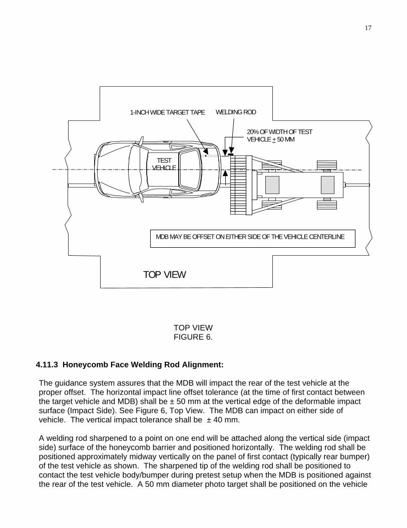
TOP VIEW
TESTVEHICLE
20% OF WIDTH OF TEST VEHICLE + 50 MM
WELDING ROD1-INCH WIDE TARGET TAPE
MDB MAY BE OFFSET ON EITHER SIDE OF THE VEHICLE CENTERLINE
TOP VIEW FIGURE 6.
4.11.3 Honeycomb Face Welding Rod Alignment: The guidance system assures that the MDB will impact the rear of the test vehicle at the proper offset. The horizontal impact line offset tolerance (at the time of first contact between the target vehicle and MDB) shall be ± 50 mm at the vertical edge of the deformable impact surface (Impact Side). See Figure 6, Top View. The MDB can impact on either side of vehicle. The vertical impact tolerance shall be ± 40 mm. A welding rod sharpened to a point on one end will be attached along the vertical side (impact side) surface of the honeycomb barrier and positioned horizontally. The welding rod shall be positioned approximately midway vertically on the panel of first contact (typically rear bumper) of the test vehicle as shown. The sharpened tip of the welding rod shall be positioned to contact the test vehicle body/bumper during pretest setup when the MDB is positioned against the rear of the test vehicle. A 50 mm diameter photo target shall be positioned on the vehicle

18
so that the tip of the welding rod is located in the center of the target. The welding rod shall be attached to the vertical surface of the honeycomb barrier with duct tape on the impacted side (depending on which side the offset test is conducted). During the impact event, the point of the welding rod will provide a permanent indication on the test vehicle impact line.

19
WELDING ROD PLACEMENT FIGURE 7.
TAPE
REAR IMPACT POINT ALIGNMENT
2" (50 mm) 2" (50 mm)
Horizontal Impact Line
Vertical Impact Line
50 mm (2.0")
50 mm (2.0") Tape Target
REAR OF VEHICLE
IMPACT REFERENCE LINE
MOVING DEFORMABLE BARRIER
1” TARGET TAPE ALIGNED ON IMPACT REFERENCE LINE OF SUFFICiENT LENGTH FOR OVERHEAD CAMERA TO VERIFYIMPACT POINT OF MDB
The IMPACT REFERENCE LINE is located a distance equal to 20% of the width of test vehicle from the vehicle centerline, ± 50 mm. A 1-inch wide target tape shall be place along the longitudinal plane of the impact reference line on the vehicle top surface. The target tape shall be of sufficient length for the overhead camera to verify impact point of MDB.
Record the vertical and horizontal distance from the impact point to the target center on the Post-Test Data Sheet. 5.0 Compliance Test Execution 5.1 Impact. The moving barrier shall be propelled and guided per 5.1.1 and 5.1.2 5.1.1 Impact Speed Guide the moving barrier so that it travels in a straight line, with no significant lateral, vertical or rotational movement. The moving barrier impacts the rear of the stationary test vehicle at a speed of 79.3 km/h ± 0.8 km/h 5.1.2 Impact Angle

20
Impact the moving barrier into the stationary test vehicle such that the longitudinal centerline of the MDB is between 85° and 95° to the transverse plane perpendicular with the longitudinal centerline of the target vehicle (see figure 6). The offset shall be equal to 20% of the maximum width of the vehicle + 50 mm. The contractor shall take post crash still color photographs, as identified in the pre-test still photograph section (4.11.2.1). 5.2 Collection Of Stoddard Spillage Collect Stoddard solvent spillage, if any, immediately after impact using the most efficient method available. Weigh the total amount of spillage. Stoddard solvent spillage, from the moment the vehicle ceases motion, shall not exceed a total of 142 g for the 5-minute period after the vehicle comes to rest. 5.3 Static Rollover Within 30 minutes after the impact test, the test vehicle shall be rotated on the Static Rollover Device. The device shall successively increment of 90° through 360° at a uniform rate, with a full 90° of rotation taking place in any time interval from 1 to 3 minutes. After reaching each 90° increment the vehicle is held in that position for 5 minutes. Refer to Appendix 3, additionally, if the contractor is testing a school bus. NOTE: If there is an indication of a test failure during or just after the impact test, DO NOT conduct the static rollover test. (1) Remove test dummies and de-power systems. (2) Carefully secure the test vehicle on the Static Rollover Device so as not to cause any damage to fuel system components or fuel lines. (3) Begin rotating the vehicle to the first 90° increment. Record the time at which rotation begins and ends, increment of rotation shall be completed within a maximum of 3 minutes. The vehicle shall be held in this position for 5 minutes after rotation ends. (4) Collect Stoddard solvent spillage, if any, from the time rotation began up to 5 minutes thereafter. Note: If there is an indication of a test failure during any 90° increment of the rollover test, STOP THE TEST. Do not continue to the next successive 90° increment. (5) Change collection containers. Record any spillage that occurs during the 6th minute after the onset of rotation or when rotation began. (6) If required, change collection containers. Record any spillage that occurs during the 7th minute after the onset of rotation or when rotation began. (7) If required, change collection containers. Record any spillage that occurs during the 8th minute after the onset of rotation or when rotation began.

21
Repeat for 90° to 180°, 180° to 270° and 270° to 360° increments. Pass or Fail Criteria - Stoddard solvent spillage, from the onset of rotational motion, shall not exceed a total of 142 grams for the first 5 minutes of testing at each successive 90° increment. For the remaining testing period, at each increment of 90°, solvent spillage during any 1-minute interval shall not exceed 28 grams. In the event of a failure the contractor shall photograph the containers containing the Stoddard solvent. 6.0 Post-Crash Test After the test vehicle has undergone the crash test, the contractor shall complete the following:
a. FMVSS 301 data sheets b. Post Test photos c. Post test data sheet 4 and complete any other data sheets not completed d. Vehicle Condition Report e. Complete test report for submission to the COTR
The contractor shall re-verify all instrumentation and check data sheets and photographs. Make sure data is recorded in all data blocks on every compliance test data sheet.
Consult the contract for all required deliverables and timelines.

22
7.0 Data Sheets
Data Sheet No. 1 Test Vehicle Specifications
TEST VEHICLE INFORMATION (from Moroney Label): NHTSA No.: ; Year/Make/Model/Body Style: Engine Displacement: ________ cc Transmission Data: manual automatic Final Drive Data: front wheel drive rear wheel drive all wheel drive Major Options: Date Received: ; Odometer Reading: miles Plant:____________ DATA FROM VEHICLE'S CERTIFICATION LABEL: Vehicle Manufactured By: Date of Manufacture: VIN: GVWR: kg. ; GAWR — Front: kg. ; GAWR — Rear: kg. DATA FROM VEHICLE'S TIRE PLACARD: Location of Placard on Vehicle: Tire Pressure With Maximum Capacity Vehicle Load: Front: _ kPa; Rear: kPa Recommended Tire Size: Recommended Load Range: Recommended Cold Tire Pressure: Front = KPa; Rear = kPa Size of Tires on Test Vehicle: (vehicle must have tire size as recommended) Type of Spare Tire: full size space saver Vehicle Capacity Data Type of Front Seat(s): Number of Occupants: Front = ; Rear = ; Total = A. VEHICLE CAPACITY WEIGHT (VCW) = kg. B. Number of Occupants x 68 kg. = kg. RATED CARGO AND LUGGAGE WEIGHT (RCLW) = (A - B) = kg. RECORDED BY: ; DATE: _____________________ APPROVED BY: ____________________________

23
Data Sheet No. 2 Pre-Test Data
WEIGHT OF TEST VEHICLE: Unloaded Vehicle Weight (w/ maximum fluids) Right Front = kg. Right Rear = kg. Left Front = kg. Left Rear = kg. TOTAL FRONT = kg. TOTAL REAR = kg. % of TOTAL = % % of TOTAL = kg. TOTAL UNLOADED VEHICLE WEIGHT = kg. Calculation of Target Test Weight (TTW) 1. Total Unloaded Vehicle Weight = kg.
2. Rated Cargo & Lugg. Weight (RCLW) = kg. (for truck or MPV use 135 kg or rated luggage capacity, whichever is less)
3. Weight of 2 Dummies (74 kg. each) = kg. TARGET TEST WEIGHT = 1 + 2 + 3 = kg. As Tested Test Weight of Vehicle, Dummies and kg of Cargo Weight Right Front = kg. Right Rear = kg. Left Front = kg. Left Rear = kg. TOTAL FRONT = kg. TOTAL REAR = kg. % of TOTAL = % % of TOTAL = % TOTAL TEST WEIGHT = kg. Weight of Ballast secured in cargo area = kg. Type of Ballast: Method of Securing Ballast: Vehicle Components Removed for Weight Reduction_______________

24
Data Sheet No. 2
Pre-Test Data (continued) VEHICLE ATTITUDE As Delivered — Right Front: mm Left Front: mm Right Rear: mm Left Rear: mm As Tested — Right Front: mm Left Front: mm Right Rear: mm Left Rear: mm FUEL SYSTEM DATA: Fuel System Capacity Listed in Owner's Manual = liters Usable Capacity Figure Furnished By COTR = liters Test Volume Range (91 to 94% of Usable Capacity) —
liters to liters ACTUAL TEST VOLUME = liters (with entire fuel system filled) Test Fluid Type: Stoddard solvent Test Fluid Specific Gravity: _________ Test Fluid Kinematic Viscosity: centistokes Test Fluid Color: ("red" is preferred) Type of Vehicle Fuel Pump: ___________ Activate Electric Fuel Pump Operation with Ignition Switch ON but Engine OFF __ Comments (noticeable attributes of fuel system components, capacity, etc.) RECORDED BY: ; DATE: _____________________

25
APPROVED BY: ____________________________

26
Data Sheet No. 3 Moving Barrier Data
Moving Barrier’s Test Weight: Right Front _____kg Right Rear _____kg Left Front _____kg Left Rear _____kg Total Front Weight: _____kg Total Rear Weight _____kg Total Test Weight (1361 + 4.5 kg) _____kg Tires (Mfr, line, size):_________________________________(P205/75R15) Tire Pressure: Right Front (30 psi, nominal) _____psi Right Rear (30 psi, nominal) _____psi Left Front (30 psi, nominal) _____psi Left Rear (30 psi, nominal) _____psi Brake Abort system?(Yes/No):______ Date of last calibration:________ RECORDED BY: ; DATE: _____________________ APPROVED BY: ____________________________

27
Data Sheet No. 4 Post Test Data
TYPE OF TEST: TEST DATE: ; TIME: ; TEMP.: °C NHTSA NO.: ; VIN: REQUIRED IMPACT VELOCITY RANGE: to km/h ACTUAL IMPACT VELOCITY: (speed traps located within 1.5 m of impact plane) Trap No. 1 = km/h Trap No. 2 = km/h Average Impact Speed = km/h WELDING ROD IMPACT POINT Vertical distance from target center (+ above target / - below target) ________mm Horizontal distance from target center (+ to the right / - to the left) _________mm STODDARD SOLVENT SPILLAGE MEASUREMENT: A. From impact until vehicle motion ceases — Actual = g Maximum Allowable = 28 g B. For 5 minute period after vehicle motion ceases — Actual = g Maximum Allowable = 28 g C. For next 25 minutes — Actual = g Maximum Allowable = 28 g/minute D. Provide Spillage Details: RECORDED BY: ; DATE: _____________________ APPROVED BY: ____________________________

28
Data Sheet No. 5 STATIC ROLLOVER TEST DATA
0°/360 °
REAR VIEW
REAR VIEW
90 °
REAR VIEW
90°
180 °
REAR VIEW A. Test Phase = 0° to 90° Determination of Stoddard Solvent Collection Time Period: 1. Rollover Fixture 90° Rotation Time = minutes, seconds (Specified Range is 1 to 3 minutes) 2. FMVSS 301 Position Hold Time = 5 minutes, 0 seconds 3. TOTAL = minutes, seconds 4. NEXT WHOLE MINUTE INTERVAL = minutes Actual Test Vehicle Stoddard Solvent Spillage: 1. First 5 minutes from onset of rotation = g (142 g allowed) 2. 6th minute = g (28 g allowed) 3. 7th minute = g (28 g allowed) 4. 8th minute = g (28 g allowed) Provide Details of Stoddard Solvent Spillage Locations —

29
B. Test Phase = 90° to 180° Determination of Stoddard Solvent Collection Time Period: 1. Rollover Fixture 90° Rotation Time = minutes, seconds (Specified Range is 1 to 3 minutes) 2. FMVSS 301 Position Hold Time = 5 minutes, 0 seconds 3. TOTAL = minutes, seconds 4. NEXT WHOLE MINUTE INTERVAL = minutes Actual Test Vehicle Stoddard Solvent Spillage:
1. First 5 minutes from onset of rotation = g (142 g allowed) 2. 6th minute = g (28 g allowed) 3. 7th minute = g (28 g allowed) 4. 8th minute = g (28 g allowed) Provide Details of Stoddard Solvent Spillage Locations — C. Test Phase = 180° to 270° Determination of Stoddard Solvent Collection Time Period: 1. Rollover Fixture 90° Rotation Time = minutes, seconds (Specified Range is 1 to 3 minutes) 2. FMVSS 301 Position Hold
30
Time = 5 minutes, 0 seconds 3. TOTAL = minutes, seconds 4. NEXT WHOLE MINUTE INTERVAL = minutes Actual Test Vehicle Stoddard Solvent Spillage:
1. First 5 minutes from onset of rotation = g (142 g allowed) 2. 6th minute = g (28 g allowed) 3. 7th minute = g (28 g allowed) 4. 8th minute = g (28 g allowed) Provide Details of Stoddard Solvent Spillage Locations — D. Test Phase = 270° to 360° Determination of Stoddard Solvent Collection Time Period: 1. Rollover Fixture 90° Rotation Time = minutes, seconds (Specified Range is 1 to 3 minutes) 2. FMVSS 301 Position Hold Time = 5 minutes, 0 seconds 3. TOTAL = minutes, seconds 4. NEXT WHOLE MINUTE INTERVAL = minutes Actual Test Vehicle Stoddard Solvent Spillage:
1. First 5 minutes from onset of rotation = g

31
(142g allowed) 2. 6th minute = g (28 g allowed) 3. 7th minute = g (28 g allowed) 4. 8th minute (if required) = g (28 g allowed) Provide Details of Stoddard Solvent Spillage Locations — RECORDED BY: ; DATE: _____________________ APPROVED BY: ____________________________

32
8.0 Forms
FORM 1 TEST VEHICLE INFORMATION
VEHICLE MODEL YEAR/MAKE: MODEL/BODY STYLE: 1. NOMINAL DESIGN RIDING POSITION –
SEAT CUSHION
LEFT SIDE VIEW
ADJUSTER
INCLINOMETER
SEAT BACK
DEGREES
UPRIGHT POSITION
FRONT SEAT ASSEMBLYFor adjustable driver and passenger seat backs. Please describe how to position the inclinometer to measure the seat back angle. Include description of the location of the adjustment latch detent if applicable. Indicate, if applicable, how the detents are numbered
(Is the first detent "0" or "1"?). Seat back angle for driver's seat = ° Measurement Instructions: Seat back angle for passenger's seat = ° Measurement Instructions:
33
2. SEAT FORE & AFT POSITIONS –
Provide instructions for positioning the driver and front outboard passenger seat(s) in the center of fore and aft travel. For example, provide information to locate the detent in which the seat track is to be locked.
Positioning of the driver's seat: Positioning of the passenger's seat (if applicable): 3. FUEL TANK CAPACITY DATA – 3.1 A. "Usable Capacity" of standard equipment fuel tank = gallons. B. "Usable Capacity" of optional equipment fuel tank = gallons. C. "Usable Capacity" of vehicle(s) used for certification testing to
requirements of FMVSS 301 = gallons. Operational Instructions: 3.2 Amount of Stoddard solvent added to vehicle(s) used for certification test(s) = gallons 3.3 Is vehicle equipped with electric fuel pump? Yes- ; No-
If YES, explain the vehicle operating conditions under which the fuel pump will pump fuel.
4. STEERING COLUMN ADJUSTMENT
Steering wheel and column adjustments are made so that the steering wheel hub is at the geometric center of the locus it describes when it is moved through its full range of driving positions. If the tested vehicle has any of these adjustments, does your company use any specific procedures to determine the geometric center.
Operational Instructions:

34
FORM 2
LABORATORY NOTICE OF TEST FAILURE TO OVSC Completed and FAXED to the COTR within 48 hours after identification of failure
TEST DATE: LABORATORY: CONTRACT NO.: ; DELV. ORDER NO.: LAB PROJECT ENGINEER'S NAME: TEST VEHICLE YEAR/MAKE/MODEL/BODY STYLE: VEH. NHTSA NO.: ; VIN: MFR: TEST FAILURE DESCRIPTION: FMVSS REQUIREMENT, PARAGRAPH S : NOTIFICATION TO NHTSA (COTR): DATE: ; BY: REMARKS:
35
APPENDIX 1 ANTI-SIPHONING DEVICE FOR ALCOHOL FUEL VEHICLES
APPLICABLE ONLY TO THOSE VEHICLES TYPES THAT ARE CURRENTLY SUBJECT TO FMVSS 301 AND THAT ARE DESIGNED TO OPERATE WITH AT LEAST 20 PERCENT ALCOHOL FUEL CONTENT.
A1.1 TEST EQUIPMENT DESCRIPTION
The following is a list of the minimum suggested test equipment needed to perform the anti-siphoning test for alcohol fuel vehicles (S6.6).
A straight vinyl plastic or rubber hose of 120 centimeters (cm), +0.00, -
0.60 (47.20 inches, +0.00, -0.25) length. The hose will have an outside diameter of 5.20 millimeters (mm), +0.00, -0.26 (0.20 inches, +0, -0.01).
A1.2 DEFINITIONS
ALCOHOL FUEL VEHICLES
Each vehicle manufactured to operate on an alcohol fuel (e.g., methanol, ethanol) or a fuel blend containing at least 20 percent alcohol fuel.
A1.3 COMPLIANCE TEST EXECUTION
Position the test vehicle on a level surface, fill the fuel tank with Stoddard solvent to between 90 to 95 percent of its useable capacity. Insert one end of the test hose into the fuel filler neck and determine whether the hose will pass through the anti-siphoning device and reach the solvent. Insert the test hose as far into the fuel filler neck as possible or until it is completely within the fuel filler neck or blocked by the anti- siphoning device. During insertion, keep the test hose concentric with the opening of the anti-siphoning device, if possible.
Measure the length of any remaining portion of the test hose outside of the fuel filler neck.
Record the measurement in Data Sheet 1.
Pull the test hose out of the fuel filler neck carefully for examination. If there is evidence that the hose had contacted the surface of the Stoddard solvent in the tank, then measure the length of the hose that was submerged in the solvent.
The vehicle fails the test if there is evidence that the hose end contacted the surface of the solvent in the tank.

36
DATA SHEET A1.1
ANTI-SIPHONING DEVICE FOR ALCOHOL FUEL VEHICLES VEH. MOD YR/MAKE/MODEL/BODY: VEH. NHTSA NO.: ; VIN:____________________ VEH. BUILD DATE: ; TEST DATE:_________ TEST LABORATORY: ________________________ OBSERVERS: _______________________________ 1. Provide a description of the anti-siphoning device if possible. 2. Did the test hose pass through the anti-siphoning device opening? Yes- No- 3. The test hose length outside of the fuel filler neck at maximum insertion: Length = cm 4. The maximum inserted test hose length is (120.00 cm - measurement from item
3): Length = cm 5. Was there evidence that the test hose contacted the surface of the Stoddard
fluid in the fuel tank of the test vehicle? Yes- (Fail) No- (Pass) 6. Measure the length of the portion of the hose that was submerged in the
Stoddard solvent: Length = cm
RECORDED BY: ; DATE: _____________________

37
APPROVED BY: ____________________________

38
APPENDIX 2
MODIFIED FMVSS 301 TEST, REAR IMPACT ONLY
FOR THE PURPOSE OF ACQUIRING INFORMATION FOR APPLIED RESEARCH, FMVSS 301, FUEL SYSTEM INTEGRITY TEST - REAR IMPACT, IS MODIFIED FOR EACH INSTRUMENTED DUMMY WITH THE FOLLOWING ADDITIONAL TEST AND DATA ACQUISITION REQUIREMENTS:
A2.1 TEST EQUIPMENT DESCRIPTION
The following is a list of the minimum additional test equipment needed to perform the modified FMVSS 301 test.
A. A anthropomorphic test dummy, Part 572E (Hybrid III), Part 572O (Hybrid
III), Thor, or BioRid etc. B. Sensor to measure head rotation directly or calculated from angular velocity
for the test dummy specified above. C. Sensor to measure chest rotation directly or calculated from angular velocity
for the test dummy specified above. D. Load cell to measure lower neck loads. E. Lower neck accelerometer for the test dummy specified above. F. Sensor to measure vehicle rotation directly or calculated from angular
velocity. G. SAE J826 manikin. H. Head Restraint Measuring Device (Insurance Corporation of British Colombia
(ICBC) machine). I. Sensors to measure rotation for both the left and right side seat back directly
or calculated from angular velocity. J. Head Center of Gravity (C.G.) Triaxial Accelerometers for the test dummy
specified above. K. Chest C.G. Triaxial Accelerometers for the test dummy specified above. L. Pelvis C.G. Triaxial Accelerometers for the test dummy specified above. M. Load cell to measure upper neck loads. N. Load cells to measure femur loads. O. Sensors to measure vehicle acceleration, passenger seat belt motion
(playout), time of head to heard restraint contact, and passenger seat belt load.
P. Data recording equipment having sufficient channels to record the necessary time history. Each data channel shall consist of a sensor, signal conditioner, data acquisition device, and all interconnecting cables and shall conform to the requirements of SAE Recommended Practice J211.
39
A2.2 ADDITIONAL INSTRUMENTATION
Instrument the anthropomorphic test dummy as follows (Actual dummy and type
of sensors used will be chosen in coordination with OVSC and OCR):
A. Head rotation about the y-axis (GFE*). B. Chest rotation about the y-axis (GFE*). C. Head C.G. Triaxial Accelerometers D. Chest C.G. Triaxial Accelerometers E. Pelvis C.G. Triaxial Accelerometers F. Lower neck accelerometer. G. Left femur load cell, single axis H. Right femur load cell, single axis I. Upper Neck
1. 3-axis Neck Force Transducers (GFE*) 2 3-axis Neck Moment Transducers (GFE*) J. Lower Neck 1. 3-axis Neck Force Transducers (GFE*) 2 3-axis Neck Moment Transducers (GFE*)
* Government Furnished Equipment Dummy calibration, according to the appropriate Dummy Performance Calibration Procedure, shall be performed prior to the start of testing, after every fifth test, and at the completion of testing. Instrument the test vehicle to record the following:
A. Passenger left seat back rotation about the y-axis (GFE*) B. Passenger right seat back rotation about the y-axis (GFE*) C. Passenger door sill rotation about the y-axis (GFE*) D. Primary and redundant accelerometers to record occupant compartment
acceleration E. Driver seat belt motion (playout) F. Driver seat belt load
NOTE: Location of transducers will be determined in coordination with the
Office of Vehicle Safety Compliance (OVSC) and the Office of Crashworthiness Research (OCR).
A.2.3 ONBOARD CAMERA REQUIREMENT
One high speed digital camera (1,000 frames/second) placed on/in the vehicle to acquire improved film coverage of seat/dummy/belt dynamics in a rear crash. The resolution of the high speed digital camera shall meet the specifications from section 9.2 Camera Coverage of this test procedure. Time zero impact mark must be registered on the high speed video

40
to indicate when contact with the barrier is made in a crash test. Actual camera location will be chosen in coordination with OVSC and OCR.
A.2.4 REPORTS AND ELECTRONIC TEST DATA A. Plots to be included in test report — Lower neck acceleration vs. time Lower neck X,Y,Z force vs. time Lower neck X,Y,Z moment vs. time Vehicle angular velocity vs. time (if applicable) Vehicle rotation vs. time Left side seat back angular velocity vs. time (if applicable) Left side seat back rotation vs. time Head angular velocity vs. time (if applicable) Head rotation vs. time Chest angular velocity vs. time (if applicable) Chest rotation vs. time
B. Measurements of the head restraint height and backset and note if the restraint locks in the adjusted position.
C. Note any deformation of the seat and attachment points to the floor D. Note the type of recliner mechanism and any deformation of the recliner
mechanism. Also note if there is a recliner mechanism on each side. E. One set of still photos in digital format (JPEG). The JPEG files shall have
the same naming convention as used on the photos in the final report. F. One final report in PDF format.
Additional information included in reports and electronic test data for the optional seat translation measurement device.
A. Plots to be included in test report –
String displacement vs. time for the left side of the seat from the string potentiometer
Rotation vs. time for the for the left side of the seat from the rotary potentiometer String displacement vs. time for the right side of the seat from the string
potentiometer Rotation vs. time for the for the right side of the seat from the rotary
potentiometer Displacement in the x-direction vs. time for the point of interest on the seat
B. Provide data sheet of the test setup of the optional seat translation measurement device.
A2.5 FRONT SEAT CUSHION ADJUSTEMENT Adjustable front seat are adjusted according to the test dummy used. For the
Part 572 tests dummies shall be positioned according the procedure in Procedure TP208-12 dated January 14, 2003. The final position of the seat cushion will be determined in coordination with the Office of Vehicle Safety Compliance (OVSC) and the Office of Crashworthiness Research (OCR).

41
A2.6 FRONT SEAT BACK ADJUSTEMENT Place the front seat back to give a torso angle of 25 degrees + 1 degrees as
measured by the SAE J826 manikin (not furnished by the government). The final seat back torso angle will be determined in coordination with the Office of Vehicle Safety
Compliance (OVSC) and the Office of Crashworthiness Research (OCR).
A2.7 HEAD RESTRAINT POSITIONING AND MEASUREMENTS The head restraint position will be determined in coordination with the Office of
Vehicle Safety Compliance (OVSC) and the Office of Crashworthiness Research (OCR). The head restraint height and backset shall be measured according to the NPRM for FMVSS No. 202 (66 FR 968 – January 4, 2001). The ICBC machine will be government furnished equipment (GFE).
A2.8 DUMMY POSITIONING AND MEASUREMENTS
Anthropomorphic Test Dummy shall be placed in the passenger location and positioned with the appropriately procedure defined in TP208-12 dated January 14, 2003. The test lab shall provide measurements of the dummy in accordance with Data Sheet 35 of TP208-12 dated January 14, 2003. The final position procedure of the dummy will be determined in coordination with the Office of Vehicle Safety Compliance (OVSC) and the Office of Crashworthiness Research (OCR).
A2.9 ADDITIONAL TARGETS Location of additional targets will be determined in coordination with the Office of Vehicle Safety Compliance (OVSC) and the Office of Crashworthiness Research (OCR).
A2.10 ELECTRONIC DATA SUBMISSION FOR ALL STANDARDS
An electronic data submission (CDs/diskettes), formatted in accordance with the NHSTA EV5 data format as specified in the Version 5 Test Reference Guide, Volume 1: Vehicle Tests (VTRG), shall be required for each test conducted for OVSC. Copies of the guide may be downloaded from the web site, http://www-nrd.nhtsa.dot.gov/software/entree/index.htm
The initial electronic data submission post-test will contain specification and measurement data in this EV5 format. Subsequent submission of the digital photos (JPEG), AVI, and the PDF copy of the final report shall also be prepared in accordance with the specifications for submission of these deliverables as defined in the Guide (VTRG).

42
Each submission shall include the raw sensor outputs measured to determine compliance to the standard, such as acceleration, force, displacement, etc.
Any questions concerning preparation of the electronic data submission shall be directed to:
Barbara Hennessey US/DOT NHTSA/NVS-321 400 Seventh Street, SW Washington, DC 20590 PH: 202-366-4714 Fax: 202-366-3505 e-mail: [email protected]
A2.11 GOVERNMENT TEST INFORMATION SHEET
The Government will furnish an information sheet when this option is exercised for each individual test or series of tests. At a minimum the information sheet will include the following:
A. Selection dummy and types of sensors B. Location of transducers C. Position of seat cushion D. Final seat back torso angle E. Head restraint position F. Final position procedure for the dummy G. Camera location(s) H. Additional targets I. Details on mounting the STMD J. Location of additional channels K. Pre and Post seat back angle