Embed Size (px)
Citation preview
Page i
U.S. DEPARTMENT OF TRANSPORTATION
FEDERAL AVIATION ADMINISTRATION
ORDER JO 6191.5
Effective Date: 11/07/2015
Implementation Date: 12/15/2015
SUBJ: STANDARD TERMINAL AUTOMATION REPLACEMENT SYSTEM (STARS)
MAINTENANCE TECHNICAL HANDBOOK (MTHB) GENERATION 4 (G4) This Maintenance Technical Handbook (MTHB) provides guidance, standards, tolerances and procedures applicable to the maintenance and inspection of the STARS automation system for Generation 4 (G4) and later hardware configurations until such time of another issuance that pertains to an evolved STARS configuration. This MTHB applies to Automated Radar Terminal System (ARTS) facilities that transition to the STARS G4 platform, legacy STARS facilities with G1/G2 configurations that upgrade to STARS G4 and facilities that deploy with STARS G4. Any questions concerning this handbook should be di rected to the STARS Second Level Engineering Support Group. If there is an e mergency or critical support is required, please contact the PMO Air Traffic Services Help Desk at 1(800) 377-0308.
Page ii
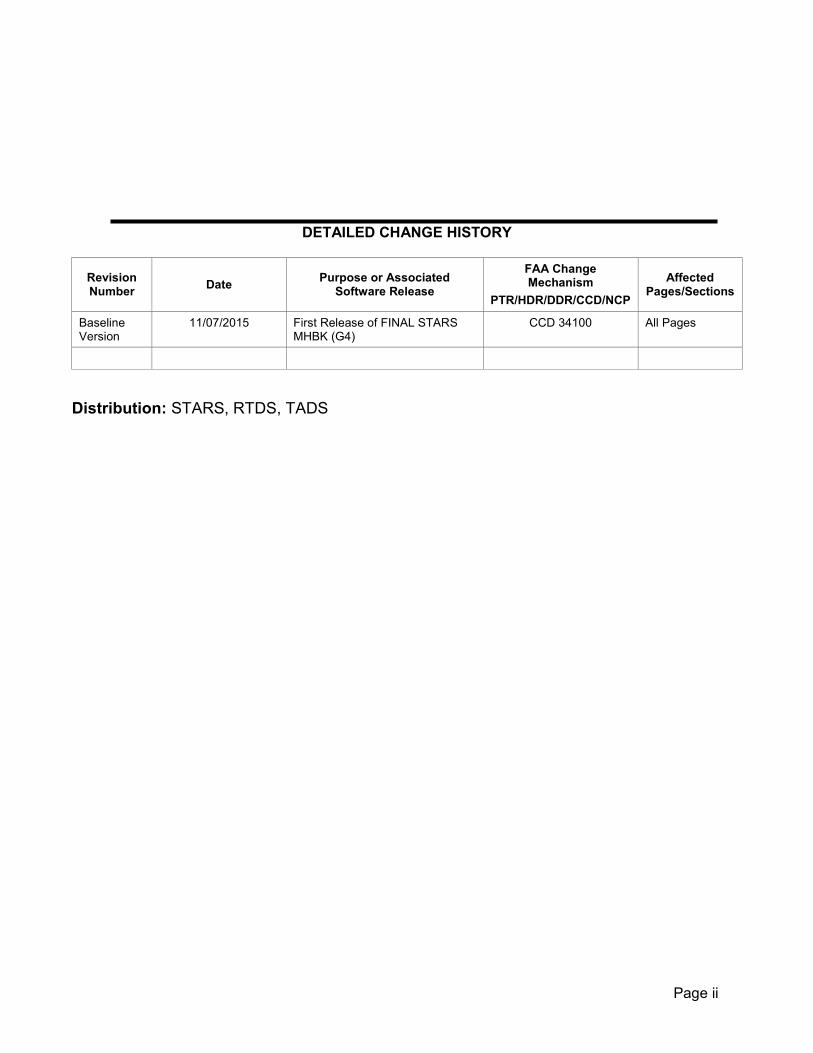
DETAILED CHANGE HISTORY
Revision Number Date Purpose or Associated
Software Release
FAA Change Mechanism
PTR/HDR/DDR/CCD/NCP
Affected Pages/Sections
Baseline Version
11/07/2015 First Release of FINAL STARS MHBK (G4)
CCD 34100 All Pages
Distribution: STARS, RTDS, TADS

Page iii
Table of Contents
Chapter 1. General Information and Requirements ................................................................ 1 1-1. Purpose. .......................................................................................................................... 1 1-2. Audience. ........................................................................................................................ 1 1-3. Where Can I Find This Change Order? ........................................................................... 1 1-4. Cancellation..................................................................................................................... 1 1-5. Explanation of Changes. ................................................................................................. 1 1-6. Certification. .................................................................................................................... 1 1-7. Aircraft Accident. ............................................................................................................. 3 1-8. Maintenance and Modification Procedure. ....................................................................... 3 1-9. Risks. .............................................................................................................................. 3 1-10. Implementation Date. ...................................................................................................... 4 1-11. Safety. ............................................................................................................................. 4 1-12. Coordination. ................................................................................................................... 4 1-13. Flight Inspection. ............................................................................................................. 4 1-14. Technical Inspection. ....................................................................................................... 4 1-15. Periodic Maintenance. ..................................................................................................... 4 1-16. Test Equipment and Tools For Periodic Maintenance. ..................................................... 5 1-17. Modification Policy. .......................................................................................................... 5 1-18. Maintenance and Diagnostic Manuals. ............................................................................ 5 1-19. FAA Forms. ..................................................................................................................... 5 1-20. FAA Orders and Handbooks. ........................................................................................... 5 1-21. System Security. ............................................................................................................. 5 1-22. – 1-99. Reserved. ............................................................................................................ 6 Chapter 2. Technical Characteristics....................................................................................... 7 2-1. Purpose. .......................................................................................................................... 7 2-2. Description. ..................................................................................................................... 7 2-3. Theory. ............................................................................................................................ 7 2-4. FSL/SYS1 System Functional Description. ...................................................................... 8 2-5. EFSL/SYS2 System Functional Description................................................................... 11 2-6. Inter-Facility Data (IDAT). .............................................................................................. 11 2-7. STARS Block Diagram. ................................................................................................. 11 2-8. – 2-99. Reserved. .......................................................................................................... 15 Chapter 3. Standards and Tolerances ................................................................................... 16 3-1. General. ........................................................................................................................ 16 3-2. Overall TARS System Status. ........................................................................................ 17 3-3. PARROT/PE Report Check. .......................................................................................... 17 3-4. Radar To Display Alignment. ......................................................................................... 18 3-5. RTQC Check Report Check. ......................................................................................... 19 3-6. TARS Sensor Registration Certification. ........................................................................ 25
Page iv
3-7. TARS Sensor Registration Performance. ...................................................................... 26 3-8. – 3-11. Reserved .......................................................................................................... 28 3-12. Overall Equipment Status. ............................................................................................. 28 3-13. Single Service Resource Redundancy........................................................................... 29 3-14. FSL/EFSL Availability. ................................................................................................... 29 3-15. Flight Data Processing Certification. .............................................................................. 29 3-16. System Status Alert Color Check. .................................................................................. 29 3-17. Summarization Report Check. ....................................................................................... 29 3-18. Service Level Switchover............................................................................................... 31 3-19. Leap Second Check. ..................................................................................................... 31 3-20. Reserved. ...................................................................................................................... 31 3-21. CDR Data Check. .......................................................................................................... 31 3-22. Periodic Certification Test. Variable Site Parameter (VSP). ........................................... 31 3-23. FS to EFS Synchronization Check. ................................................................................ 31 3-24. Tower Radar to Display Alignment Check. .................................................................... 31 3-25. Tower ADS-B Test Target Accuracy. ............................................................................. 31 3-26. Reserved. ...................................................................................................................... 31 3-27. ADSS Certification. ........................................................................................................ 31 3-28. ADSS Performance Parameters. ................................................................................... 32 3-29. ADSS Performance Verification. .................................................................................... 33 3-30. – 3-31. Reserved. .......................................................................................................... 33 3-32. TSPAD MCW Icon Check. ............................................................................................. 33 3-33. TSPAD Accuracy Check. ............................................................................................... 34 3-34. TSPAD Update Rate Check. ......................................................................................... 34 3-35. TSPAD Sensor Availability. ........................................................................................... 35 3-36. TSPAD Display Entry and Display Processing. .............................................................. 35 3-37. MLAT Sensor Reliability and Performance Parameters. ................................................ 36 3-38. FMA Alerts Check.......................................................................................................... 36 3-39. TSPAD Map Accuracy. .................................................................................................. 36 3-40. FMA Linearity/Geometric Distortion. .............................................................................. 36 3-41. – 3-45. Reserved. .......................................................................................................... 37 3-46. G4 Gang Switch Check. ................................................................................................ 37 3-47. NUNIO. .......................................................................................................................... 37 3-48. CGW. ............................................................................................................................ 37 3-49. RDP. ............................................................................................................................. 38 3-50. TCW. ............................................................................................................................. 38 3-51. TDW. ............................................................................................................................. 39 3-52. MCW. ............................................................................................................................ 41 3-53. CDR. ............................................................................................................................. 41 3-54. RAID DRD. .................................................................................................................... 41 3-55. Reserved. ...................................................................................................................... 42

Page v
3-56. SSS. .............................................................................................................................. 42 3-57. SIM. ............................................................................................................................... 43 3-58. GPW.............................................................................................................................. 43 3-59. TDW Monitor. ................................................................................................................ 44 3-60. – 3.64. Reserved. ......................................................................................................... 44 3-65. Fixed Target Map. ......................................................................................................... 44 3-66. Verify System Date and Time. ....................................................................................... 44 3-67. Aural Alarm.................................................................................................................... 45 3-68. G4 Equipment LED Check. ............................................................................................ 45 3-69. BARCO Alignment Check. ............................................................................................. 45 3-70. Reserved. ...................................................................................................................... 45 3-71. RTDS Target Display Check. ......................................................................................... 45 3-72. RTDS Data Entry Processing and Display Check. ......................................................... 46 3-73. Reserved. ...................................................................................................................... 46 3-74. Reserved. ...................................................................................................................... 46 Chapter 4. Periodic Maintenance ........................................................................................... 47 4-1. General. ........................................................................................................................ 47 Section 1. FSL/SYS1 Performance Checks .......................................................................... 47 4-2. Daily. ............................................................................................................................. 47 4-3. Weekly. ......................................................................................................................... 48 4-4. Biweekly. ....................................................................................................................... 48 4-5. Monthly. ......................................................................................................................... 49 4-6. Quarterly. ...................................................................................................................... 49 4-7. Semiannually. ................................................................................................................ 49 4-8. Annually. ....................................................................................................................... 49 4-9. Biannually. ..................................................................................................................... 49 4-10. Triannually. .................................................................................................................... 49 4-11. As Required................................................................................................................... 49 4-12. – 4-15. Reserved. .......................................................................................................... 50 Section 2. EFSL/SYS2 Performance Checks ........................................................................ 50 4-16. Daily. ............................................................................................................................. 50 4-17. Weekly. ......................................................................................................................... 51 4-18. Biweekly. ....................................................................................................................... 51 4-19. Monthly. ......................................................................................................................... 51 4-20. Quarterly. ...................................................................................................................... 52 4-21. Semiannually. ................................................................................................................ 52 4-22. Annually. ....................................................................................................................... 52 4-23. Triannually. .................................................................................................................... 52 4-24. As Required................................................................................................................... 52 Section 3. TADS Performance Checks ................................................................................. 52 4-25. Daily. ............................................................................................................................. 52

Page vi
4-26. Weekly. ......................................................................................................................... 53 4-27. Biweekly. ....................................................................................................................... 53 4-28. Monthly. ......................................................................................................................... 53 4-29. Quarterly. ...................................................................................................................... 53 4-30. Semiannually. ................................................................................................................ 53 4-31. Annually. ....................................................................................................................... 53 4-32. Biannually. ..................................................................................................................... 53 4-33. Triannually. .................................................................................................................... 53 4-34. As Required................................................................................................................... 53 Section 4. ADSS Performance Checks ................................................................................. 54 4-35. Daily. ............................................................................................................................. 54 4-36. Weekly. ......................................................................................................................... 54 4-37. Biweekly. ....................................................................................................................... 54 4-38. Monthly. ......................................................................................................................... 55 4-39. Quarterly. ...................................................................................................................... 55 4-40. Semiannually. ................................................................................................................ 55 4-41. Annually. ....................................................................................................................... 55 4-42. Biannually. ..................................................................................................................... 55 4-43. Triannually. .................................................................................................................... 55 4-44. As Required................................................................................................................... 55 Section 5. RTDS Performance Checks ................................................................................. 55 4-45. Daily. ............................................................................................................................. 55 4-46. Weekly. ......................................................................................................................... 55 4-47. Monthly. ......................................................................................................................... 56 4-48. Quarterly. ...................................................................................................................... 56 4-49. Semiannually. ................................................................................................................ 57 4-50. As Required................................................................................................................... 57 Section 6. TSPAD Performance Checks ............................................................................... 58 4-51. Daily. ............................................................................................................................. 58 4-52. Weekly. ......................................................................................................................... 58 4-53. Quarterly. ...................................................................................................................... 58 4-54. – 4-55. Reserved. .......................................................................................................... 58 Section 7. Other Maintenance Tasks .................................................................................... 59 4-56. Daily. ............................................................................................................................. 59 4-57. Weekly. ......................................................................................................................... 59 4-58. Biweekly. ....................................................................................................................... 59 4-59. Monthly. ......................................................................................................................... 59 4-60. Bimonthly. ..................................................................................................................... 59 4-61. Quarterly. ...................................................................................................................... 59 4-62. Semiannually. ................................................................................................................ 60 4-63. Annually. ....................................................................................................................... 60
Page vii
4-64. Biennially. ...................................................................................................................... 61 4-65. As Required................................................................................................................... 61 4-66. – 4-99. Reserved. .......................................................................................................... 62 Chapter 5. Maintenance Procedures ..................................................................................... 63 5-1. General. ........................................................................................................................ 63 5-2. Technical Performance Record Entries. ........................................................................ 63 5-3. – 5-9. Reserved. ............................................................................................................ 63 Section 1. Performance Check Procedures ........................................................................ 64 5-10. MCW System Icon Check. ............................................................................................. 64 5-11. Reserved..........................................................................................................................65 5-12. TARS PARROT/PE Report Check. ................................................................................ 65 5-13. Radar to Display Alignment. .......................................................................................... 66 5-14. Radar RTQC Report Check. .......................................................................................... 67 5-15. TARS Registration Performance (CALC MODE). .......................................................... 68 5-16. TARS Registration Performance (AUTO MODE). .......................................................... 72 5-17. TARS Registration None Mode...................................................................................... 76 5-18. Summarization Report Check. ....................................................................................... 82 5-19. Service Level Switchover............................................................................................... 82 5-20. Leap Second Check. ..................................................................................................... 84 5-21. G4 Gang Switch Check. ................................................................................................ 85 5-22. Resource Verification. ................................................................................................... 85 5-23. STARS Procedure for Full Performance Verification. ..................................................... 86 5-24. Single Service Resource Redundancy........................................................................... 89 5-25. FS/EFS Availability Check. ............................................................................................ 93 5-26. FSL System FS to EFS Synchronization Check. ........................................................... 93 5-27. System Status Alert Color Check. .................................................................................. 95 5-28. IFDT Processing Input/Output Check. ........................................................................... 95 5-29. Procedure for Abbreviated Performance Verification Check Initiated from the MCW. .... 96 5-30. Procedure for Abbreviated Performance Verification Check Using Target Generator. ... 97 5-31. Tower Radar to Display Check. ..................................................................................... 99 5-32. FSL/EFSL and Support Network Information System Plus (NIS+) Check. ................... 100 5-33. Alternate Range/Azimuth Integrity Certification Method Using Registration Analysis. .. 101 5-34. Alternative Radar Accuracy Integrity Method Using Visual Checks. ............................. 102 5-35. ADSS Certification Checks. ......................................................................................... 103 5-36. ADSS Performance Checks. ....................................................................................... 105 5-37. ADSS Performance Check Baseline Procedure. ......................................................... 106 5-38. ADSS Performance Verification Procedure. ................................................................ 106 5-39. Tower ADS-B Test Target Display Check. ................................................................... 108 5-40. Registration Default Bias Correction Baseline. ............................................................ 108 5-41. Radar Performance Baseline. ...................................................................................... 109 5-42. – 5-46. Reserved. ........................................................................................................ 110

Page viii
Section 2. Other Maintenance Tasks Procedures ............................................................. 111 5-47. Fixed Target Map. ....................................................................................................... 111 5-48. Reserved. .................................................................................................................... 111 5-49. Blower Fan and Filter Inspection and Cleaning. ........................................................... 111 5-50. Rack Cabinet Physical Inspection and Cleaning. ......................................................... 112 5-51. TCW Cabinet Physical Inspection and Cleaning. ......................................................... 112 5-52. Check Connector Mating. ............................................................................................ 113 5-53. TDW Articulating Arm Check. ...................................................................................... 113 5-54. TDM HEPA Filter Inspection and Cleaning. ................................................................. 113 5-55. TDM Fan Inspection and Cleaning. ............................................................................. 114 5-56. – 5.64. Reserved. ........................................................................................................ 114 5-65. TSPAD Mono-pulse Beacon (e.g., MODE S) Operational Status................................. 114 5-66. Reserved. .................................................................................................................... 115 5-67. FMA Alerts Check........................................................................................................ 115 5-68. TSPAD Display Entry and Display Processing. ............................................................ 116 5-69. TSPAD Accuracy Check with Radar. ........................................................................... 117 5-70. TSPAD Accuracy Check with MLAT. ........................................................................... 118 5-71. Reserved. .................................................................................................................... 119 5-72. Magnification Stretch Factor Accuracy Check. ............................................................. 119 5-73. Target Update Rate for Radar. .................................................................................... 119 5-74. Reserved. .................................................................................................................... 120 5-75. MLAT Availability. ........................................................................................................ 120 5-76. MLAT Sensor Reliability and Performance Parameters. .............................................. 120 5-77. Reserved. .................................................................................................................... 122 5-78. MLAT Target Update Rate Check. ............................................................................... 122 5-79. TSPAD Map Accuracy. ................................................................................................ 122 5-80. Reserved. .................................................................................................................... 123 5-81. MLAT Fixed Target Map. ............................................................................................. 123 5-82. G4 Equipment LED Check. .......................................................................................... 123 5-83. No Print Report SAVE Procedure. ............................................................................... 129 5-84. Periodic Transfer of Saved Reports to Maintenance Laptop Procedure. ...................... 130 5-85. Periodic Reboot of Avaya FSL/EFSL LAN B Routers. ................................................. 131 5-86. Periodic Reboot of Avaya FSL/EFSL LAN A Routers. ................................................. 132 5-87. – 5-99. Reserved. ........................................................................................................ 132 Chapter 6. Flight Inspection ................................................................................................. 133 6-1. General. ...................................................................................................................... 133 6-2. – 6-99. Reserved. ........................................................................................................ 133 Appendix A. Certification Requirements ............................................................................. 134 Appendix B. Glossary of Acronyms and Terms ................................................................. 143 Appendix C. Documentation and Forms................................................................................151 Appendix D. Identification of Main Display Monitor (MDM) Version.................................. 154

Page ix
Appendix E. Radar Fixed Target Map Detail........................................................................ 156 Appendix F. ADS-B Fixed Beacon Target Map Detail ......................................................... 158

Page x
List of Figures Figure 2-1. STARS G4 Block Diagram .........................................................................................12 Figure 2-2. STARS G4 Gang Switch Diagram ..............................................................................13 Figure 2-3. STARS G4 Color Block Diagram ................................................................................14 Figure 5-1. Registration Report with DIFF columns (4) ...................................................................70 Figure 5-2. Registration Report with DIFF columns (7) ...................................................................74 Figure 5-3. Registration Tolerance CPME/PARROT GEO-BOXES ..................................................78 Figure 5-4. Simulation Control ....................................................................................................98 Figure 5-5. Registration Reports ............................................................................................... 109 Figure 5-6. Front Panel X2000 Processor .................................................................................. 124 Figure 5-7. Right-Front AT8000GS Gigabyte Switch LEDs ........................................................... 124 Figure 5-8. AT-8000 Ports, one top one; bottom with corner LEDs ................................................ 125 Figure 5-9. Sunhillo Ethernet Switch Module .............................................................................. 126 Figure 5-10. Sunhillo Processor Switch Module ............................................................................ 127 Figure 5-11. Avaya Secure Router 4134 rear panel ....................................................................... 128 Figure 5-12. Logical RS530 Line Splitter Unit ............................................................................... 129 Figure D-1. Rear view of MDM 3 (Handles) ................................................................................. 154 Figure D-2. Rear view of MDM 3 ................................................................................................ 154 Figure D-3. Rear view of MDM 4 ................................................................................................ 155 Figure D-4. Rear view of MDM 4 (Magnified) ............................................................................... 155
List of Tables Table 3-1. Paragraph Numbering System ......................................................................................16 Table 5-1. Registration Tolerances Table Fused Track Display (A) ...................................................71 Table 5-2. Registration Tolerances Table Fused Track Display (B) ...................................................76 Table 5-3. 10 Data Path Check .....................................................................................................93 Table 5-4. MLAT REFTRANS Lookup Table ................................................................................ 121 Table 5-5. MLAT REFTRANS HI LO Table .................................................................................. 122 Table 5-6. Power Supply LED Indications .................................................................................... 125 Table 5-7. System LED Indications ............................................................................................. 125 Table 5-8. Port LED Mode/Indications for AT-8000GS/24 and AT-8000GS/48 .................................. 126 Table A-1. Terminal Automated Radar Service (TARS) ................................................................. 136 Table A-2. STARS Service Level ................................................................................................ 137 Table A-3. Automatic Dependent Surveillance Service (ADSS) ...................................................... 138 Table A-4. TRACON Automation Display System (TADS) .............................................................. 139 Table A-5. Terminal Surveillance Parallel Approach Display (TSPAD) ............................................. 140 Table A-6. Radar Tower Automation Display Service (RTADS) ...................................................... 141 Table A-7. Radar Tower Display System (RTDS) .......................................................................... 142 Table B-1. Acronyms ................................................................................................................. 143 Table B-2. Terms ...................................................................................................................... 148 Table C-1. Maintenance and Diagnostic Manuals ......................................................................... 151 Table C-2. FAA Forms .............................................................................................................. 151 Table C-3. FAA Orders and Handbooks ...................................................................................... 152
11/07/2015 JO 6191.5
1
Chapter 1. General Information and Requirements
1-1. Purpose.
This MTHB provides guidance and pr escribes technical standards, tolerances, and pr ocedures applicable to the maintenance and inspection of the Standard Terminal Automation Replacement System (STARS) for Generation 4 (G4) configurations, STARS Terminal Radar Approach Control (TRACON) Automation Display System (TADS), and S TARS Radar Tower Display System (RTDS). It also provides information on special methods and techniques, which will enable Technical Operational Services (TOS) or the Department of Defense (DoD) equivalent, to achieve optimum performance from the equipment. This information augments information available in Technical Instruction Books (TIB) and other MTHBs, and complements the latest edition of Order 6000.15.
1-2. Audience.
This MTHB requires actions by the Federal Aviation Administration (FAA) Technical Operations Services (TOS) Airway Transportation System Specialist (ATSS) and DoD radar maintenance personnel at operational facilities, with the following Facility, Service and E quipment Profile (FSEP): STARS, TADS (STARS TCW), and RTDS (STARS TDW). It is distributed to offices and services within Washington Headquarters, the William J. Hughes Technical Center, the Mike Monroney Aeronautical Center, regional Air Traffic Organization (ATO) divisions, DoD facilities, and ATO field offices having the following facilities/equipment: STARS.
1-3. Where Can I Find This Change Order? An electronic version of this handbook can be found at https://employees.faa.gov/tools_resources/orders_notices/ by searching for 6191.5. It is also available on a FAA Intranet site located at http://ksn2.faa.gov under the system heading: STARS; DocType: HBK and a DoD accessible website at https://www.adx.faa.gov under the STARS document links STARS then HBK.
1-4. Cancellation.
This Order cancels 6191.3A STARS Maintenance Technical Handbook series when the facility migrates to a STARS G4 configuration.
1-5. Explanation of Changes.
This MTHB implements Configuration Control Decision (CCD) 34100. It incorporates changes resulting from the STARS physical and functional G4 modifications as well as field, service area, and headquarters comments.
1-6. Certification.
Refer to Order 6000.15, General Maintenance Handbook for National Airspace System (NAS) Facilities for guidance on the certification of systems, subsystems, and equipment. Refer to Appendix A of this MTHB for the specific certification requirements of the STARS automation systems along with its ancillary services and systems.
a. Certification Tables. Each table in Appendix A of this handbook lists the certification levels, associated certification parameters, reference paragraphs, maximum certification intervals, identification of recommended personnel responsible for certification, and the prescribed certification statements to be entered into the facility maintenance log.
b. Certification of Systems. Certification is required for the following FSEP service and systems.
11/07/2015 JO 6191.5
2
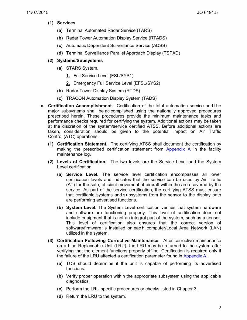
(1) Services (a) Terminal Automated Radar Service (TARS) (b) Radar Tower Automation Display Service (RTADS)
(c) Automatic Dependent Surveillance Service (ADSS)
(d) Terminal Surveillance Parallel Approach Display (TSPAD)
(2) Systems/Subsystems (a) STARS System.
1. Full Service Level (FSL/SYS1)
2. Emergency Full Service Level (EFSL/SYS2)
(b) Radar Tower Display System (RTDS)
(c) TRACON Automation Display System (TADS)
c. Certification Accomplishment. Certification of the total automation service and t he major subsystems shall be ac complished using the nationally approved procedures prescribed herein. These procedures provide the minimum maintenance tasks and performance checks required for certifying the system. Additional actions may be taken at the discretion of the system/service certified ATSS. Before additional actions are taken, consideration should be given to the potential impact on Air Traffic Control (ATC) operations. (1) Certification Statement. The certifying ATSS shall document the certification by
making the prescribed certification statement from Appendix A in the facility maintenance log.
(2) Levels of Certification. The two levels are the Service Level and the System Level certification. (a) Service Level. The service level certification encompasses all lower
certification levels and indicates that the service can be used by Air Traffic (AT) for the safe, efficient movement of aircraft within the area covered by the service. As part of the service certification, the certifying ATSS must ensure that certifiable systems and subsystems from the sensor to the display path are performing advertised functions.
(b) System Level. The System Level certification verifies that system hardware and software are functioning properly. This level of certification does not include equipment that is not an integral part of the system, such as a sensor. This level of certification also ensures that the correct version of software/firmware is installed on eac h computer/Local Area Network (LAN) utilized in the system.
(3) Certification Following Corrective Maintenance. After corrective maintenance on a Line Replaceable Unit (LRU), the LRU may be returned to the system after verifying that the element functions properly offline. Certification is required only if the failure of the LRU affected a certification parameter found in Appendix A. (a) TOS should determine if the unit is capable of performing its advertised
functions. (b) Verify proper operation within the appropriate subsystem using the applicable
diagnostics.
(c) Perform the LRU specific procedures or checks listed in Chapter 3.
(d) Return the LRU to the system.

11/07/2015 JO 6191.5
3
(e) Monitor and ensure that the LRU is operating properly in the system. (f) Log the returned element in the facility maintenance log.
(4) Certification Responsibility. Certification responsibility is assigned to the appropriate TOS who hold qualifications as defined in the latest edition of Order 6000.15, General Maintenance Handbook For National Airspace System (NAS) Facilities.
1-7. Aircraft Accident. When aircraft accidents or incidents occur, Air Traffic Organization Technical Operations personnel are responsible, when requested by the Technical Operations Aircraft Accident Representative (TOAAR) through the appropriate control center, to evaluate and document the technical performance of the facilities which may have been involved (for some facilities, it may also be necessary to remove them from service, and to conduct flight inspections). Maintenance personnel must document these activities in the maintenance log. These records are official documents, and may be used by an aircraft accident investigation board in the determination of facility operational status at the time of the accident. See the latest edition of Order 8020.16, Air Traffic Organization Aircraft Accident and Incident Notification, Investigation, and Reporting, for detailed guidance on requirements and activities following an aircraft accident/incident.
1-8. Maintenance and Modification Procedure. a. Order 6000.15, General Maintenance Handbook for NAS Facilities, this MTHB, the
applicable equipment Technical Instruction Books (TIB), and other applicable handbooks are consulted and used together by the maintenance technician in all duties and activities for the maintenance of STARS. These documents are considered collectively as the single official source of maintenance policy and direction authorized by Technical Operations Services. References located in the appropriate paragraphs of this handbook entitled Chapter 3, Standards and Tolerances, Chapter 4, Maintenance Requirements, and Chapter 5, Maintenance Procedures, indicate to the user whether this handbook and/or the equipment TIB must be consulted for a par ticular standard, key inspection element or performance parameter, performance check, maintenance task, or maintenance procedure.
b. The latest edition of Order 6032.1, National Airspace System Modification Program, contains comprehensive direction concerning the development, authorization, implementation, and recording of modifications to facilities, systems, and equipment in commissioned status. It supersedes all instructions published in earlier editions of MTHBs and related directives.
c. Refer to Order 6000.15, General Maintenance Handbook for NAS Facilities for shutdown, coordination and scheduling policy.
1-9. Risks. a. Operational. There are no operational risks associated with this MTHB. b. Safety. In compliance with the latest editions of Order 1100.161, Air Traffic Safety
Oversight, and JO 1000.37, ATO Safety Management System, all NAS changes require an SRM assessment for all MTHBs prior to delivery. The SRM information for this MTHB is available in the attached SRMD. For further guidance in developing SRM documentation, refer to the latest version of the Safety Management System (SMS) Manual.
c. Security. There are no security risks associated with this MTHB.
11/07/2015 JO 6191.5
4
1-10. Implementation Date. This MTHB must be implemented by 12/15/2015. The implementation date is when all facilities nationwide must comply with these changes. The changes may be implemented any time after the effective date, but must be i mplemented by the date located on the front of this document. If implementation date occurs during a completed task interval window then you may follow the new guidance for the certification or maintenance task(s) at the next regularly scheduled interval.
1-11. Safety. TOS shall observe all pertinent safety precautions when performing maintenance on the equipment covered in this manual. Refer to the latest edition of Order 6000.15, General Maintenance Handbook for NAS Facilities, for guidance. In addition, TOS shall comply with all federal and FAA safety regulatory requirements including, but not limited to 29 CFR 1910, OSHA General Industry Standards; 29 CFR 1926, OSHA Safety and Health Regulations for Construction; FAA Order 3900.19B, FAA Occupational Safety and Health Program; FAA-STD-G-2100g, FAA Specifications for Electronic Equipment, General Requirements; and DOT/FAA/CT-03/05 HF-STD-01, Human Factors Design Standard.
1-12. Coordination. Coordination requests shall be made in accordance with the latest edition of Order 6000.15. Those procedures require:
a. Requests for authority to remove equipment from service should be directed to the appropriate TOS Control Center and i nclude the desired time of shutdown, probable duration, and reason.
b. The TOS Control Center contacts other appropriate entities, obtains approval or justification for refusal, and advises the requesting organization or the TOS of the results.
c. The TOS should confirm the approval for the interruption with AT or TOS control center personnel immediately, prior to the shutdown, to ensure the approval status has not changed.
1-13. Flight Inspection. Normal instruction and g uidance concerning flight inspection of the basic radar system and associated equipment are contained in the latest edition of Order 8200.1, United States Standard Flight Inspection Manual. For additional information concerning flight inspections, see Chapter 6 of this order.
1-14. Technical Inspection. Facility inspections, objectively conducted, are one of the most effective tools for assuring the reliability of the National Airspace System (NAS). See the latest edition of Order 6000.15, General Maintenance Handbook for NAS Facilities, and the latest edition of Order 6040.6, Airway Facilities NAS Technical Evaluation Program, for the details on i ntervals and r esponsibilities for formal inspections.
1-15. Periodic Maintenance. a. Tasks. Chapter 4 o f this handbook establishes the tasks and schedules that are
required for the periodic maintenance of STARS. These tasks, as scheduled, are the minimum required for each of the systems to meet minimum performance standards.
b. TOS. Related information useful to TOS may be f ound in the FAA orders and handbooks, maintenance manuals, and di agnostic operating procedures listed in Appendix C of this handbook.
11/07/2015 JO 6191.5
5
c. Configurations. (1) FSL (SYS1) (2) EFSL (SYS2)
1-16. Test Equipment and Tools For Periodic Maintenance. Special tools are required for performing STARS routine maintenance. Tools that are delivered to the site with STARS equipment are listed in Technical Instruction (TI) 6191.500, STARS Interactive Electronic Technical Manual (IETM) for the SOS.
1-17. Modification Policy. a. No modification should be made to the standard equipment, facilities, software, or
procedures without proper authorization. It is recognized that there will be occasions when certain temporary repairs will be necessary when approved parts are not readily available or a design deficiency is discovered. Under such circumstances, a complete report should be submitted to the appropriate supervisor. The report should explain the nature of the problem, describe the changes made, and provide an es timate of when the equipment will be restored to its original condition. The affected equipment should be restored to its original condition as soon as possible.
b. Prior Washington headquarters approval is required before region-wide or system-wide modifications are undertaken. Regional offices may grant approval for a t emporary modification for testing purposes or for determining the feasibility of a proposed improvement. Refer to the latest edition of National Airspace System Configuration Management, and O rder 6032.1, National Airspace System (NAS) Modification Program, for further information.
c. Proposed modifications to improve system performance, increase reliability, minimize safety hazards, or increase maintenance efficiency may be s uggested by any field personnel. Such proposed modifications must be described in detail and s ubmitted through the proper channels per NAS Change Proposal (NCP), FAA form 1800-2.
1-18. Maintenance and Diagnostic Manuals. A list of maintenance and diagnostic manuals are referenced in Appendix C of this handbook.
1-19. FAA Forms. Appendix C of this handbook lists the applicable FAA forms required by this handbook.
1-20. FAA Orders and Handbooks. Appendix C of this handbook lists the latest edition of orders and handbooks referenced within this handbook. A listing of documents useful to NAS system personnel can be found in the catalog of documentation maintained by the National Airspace System Documentation Facility, found on a Federal Aviation Administration (FAA) Intranet site located at https://ksn2.faa.gov and a DoD accessible website at https://www.adx.faa.gov.
1-21. System Security. ATSS at facilities are expected to maintain user Identification (ID) and password protection for all workstations. The dissemination of the root or super-user password should be s trictly controlled and should be changed per the JO 6191.2 STARS System Administration Security Handbook schedule. Personnel should use root or super-user only when absolutely required to perform some action such as a Remove and Replace (R&R) system password restoration. The root or super-user is not meant for use in everyday operations. Extreme caution should be used when logged in as root or super-user, because certain commands may take the system down.

11/07/2015 JO 6191.5
6
All personnel who are responsible to operate the system will be assigned a separate user ID and password. Separate user IDs and passwords for each operator allow the use of audit trails to determine who performed what action on the system. Personnel who leave or no longer require access to the system will have their user IDs and passwords deleted.
1-22. – 1-99. Reserved.

11/07/2015 JO 6191.5
7
Chapter 2. Technical Characteristics
2-1. Purpose. STARS is an ai r traffic control automation system that replaces the Automated Radar Terminal System (ARTS) for FAA TRACON facilities, Tower facilities and equivalent DoD air traffic control facilities. The purpose is to provide air traffic controllers with an a irspace situational display that supports maintaining separation, navigation, and flight safety capabilities.
2-2. Description. STARS G4 is a modern, distributed, air traffic control automation system. It is comprised of two redundant levels, Full Service Level (FSL) and Emergency Full Service Level (EFSL). Despite the emergency moniker, EFSL is capable of providing the same complete air traffic control service provided by FSL. Each level has dual processor redundancy with seamless switching that uses hot-standby processor and network equipment. The STARS system receives and processes target reports, weather, and other non-target messages from terminal radar, en-route radar, multi-lateration, and Global Positioning System (GPS)-oriented sensors. Additionally, it automatically tracks primary and secondary surveillance targets and provides aircraft position information to the Enhanced Traffic Management System (ETMS). It detects unsafe proximities between tracked aircraft pairs and provides warning if tracked aircraft are detected at a dangerously low altitude. Additional features are Converging Runway Display Aid (CRDA), Controller Automation Spacing Aids (CASA), Final Monitor Aid (FMA), auto-switching to standby processors, and auto-recovery of critical resources.
2-3. Theory. STARS G4 is an open architecture, distributed software-based air traffic control automation system for Federal Aviation Administration (FAA) Terminal Radar Approach Control (TRACON) facilities, Tower facilities and equivalent Department of Defense (DoD) air traffic control facilities. It is scalable and is redundant with two operational levels, FSL and EFSL. Despite the Emergency label, EFSL is capable of full operational functionality. Within each service level there are redundant hot-standby processors for the background equipment, as well as redundant hot-standby network equipment. Display processors are redundant per their numbers, i.e., they are redundant as there are extra displays but they are not hot-standby. Switching between online and standby processors is automatic and seamless and occurs whenever the processor status message is not detected or when interface monitored communication thresholds are exceeded. In the event that a s ervice level fails, STARS G4 can notify controllers to switch to a r edundant service level. This change requires a manual switchover of surveillance and flight data and external interfaces.
a. STARS Site Types. (1) STARS consist of three basic site types:
(a) STARS Central Support Complex (SCSC)
(b) Operational Support Facility (OSF)
(c) STARS Operational Site (SOS)
(2) In addition to these basic sites, Local Towers (LT) and Remote Towers (RT) provide ATC functionality at other airport sites.
b. Site Purpose. (1) SCSC Purpose. The SCSC facility provides for centralized control of STARS field
support and s oftware development. Field support performs Program Technical Report (PTR) analysis and testing, hardware testing/analysis, and c onfiguration management. The software development improves, modifies, and tests software to
11/07/2015 JO 6191.5
8
establish software baselines, resolve existing software problems, add new functionality (incremental upgrades) to the software baseline, and to perform system level adaptation. The SCSC is located at the William J. Hughes Technical Center (WJHTC).
(2) OSF Purpose. Each OSF serves as a support facility for software maintenance to include both site adaptation data and s ite support for associated SOSs. The purpose of software maintenance is to receive operational site software releases from the SCSC, integrate site adaptation to complete the operational program, and test the entire operational program prior to implementation at an SOS.
(3) SOS Purpose. Each SOS accepts and pr ocesses surveillance and flight data information providing ATC and system information to air traffic controllers and external systems. Typically the SOS includes a local tower for local airport traffic control, and m ay support one o r more RTs. For more information, see the maintenance and diagnostic information in the STARS IETM TI 6191.500.
(4) LT Purpose. LTs are collocated at STARS SOS facilities to provide STARS display capability to radar tower display systems. Functionally, the LTs are part of the SOS and, as such, support their primary mission.
(5) RT Purpose. RTs extend the SOS facilities role by supporting satellite airports that are usually several miles away and are physically separate. Functionally, the RTs are part of the SOS and as such, support their primary mission. In addition, some RTs may have Direct Sensor Feed (DSF) used for standalone operations when the associated SOS communication links are not available.
2-4. FSL/SYS1 System Functional Description. a. FSL provides tracking for terminal and tower control areas. Automatic transfer of flight
data via Inter-Facility between FSL and A ir Route Traffic Control Centers (ARTCC) and/or TRACON facilities are also provided. FSL provides the following capabilities: (1) Search-only (2) Beacon-only (3) Radar-reinforced beacon target tracking (4) Beacon-radar correlation and tracking (5) Site registration, automatic or manual (6) Collimation corrections (7) Conflict Alert (CA)/Mode-C Intruder (MCI) processing (8) Continuous Data Recording (CDR) (9) Automatic failure recovery and reconfiguration (10) Real-Time Quality Control (RTQC) (11) Minimum Safe Altitude Warning (MSAW) (12) Multi-sensor tracking (13) Sensor Mosaic display (14) Inter-Facility and intra-facility hand-offs (15) Remote displays (16) Traffic count
11/07/2015 JO 6191.5
9
(17) Up to 32 digital maps referenced on the Display Control Bar (DCB). Up to 400 system-wide (memory permitting)
(18) Six levels of weather intensity display (19) Select up t o 16 sensors, (including but not limited to Airport Surveillance Radar
(ASR)-11, ASR-9, digitized ASR-8, Air Route Surveillance Radar (ARSR)3, ARSR4, CARSR)
(20) Workstation replay events
(21) Final Monitor Aid (FMA) capability
(22) Automatic Dependent Surveillance–Broadcast (ADS-B) target processing
(23) Fused Track Display
(24) Multi-Lateration (PRMA) input, ASTERIX Cat 10 & 48
(25) ASR-11 ASTERIX surveillance input, ASTERIX CAT 08, 34 & 48
(26) Alpha-numeric synchronization to EFSL
b. ADS-B and ASR-11 ASTERIX Target Processing. STARS supports two new surveillance Ethernet inputs into the Applications Interface Gateway (AIG), ADS-B and ASR-11 ASTERIX. ADS-B target processing is the critical service data transmitted to STARS through the AIGs. It includes surveillance data (Cat 033) and status data (Cat 023) in network ASTERIX format. U pon receipt of a LAN packet containing ASTERIX data, the Communication Gateway Workstation (CGW) (AIG) will validate it and convert it to an internal message format that will be processed by the RDP. Incoming data is uniquely identified by a combination of:
(1) Multicast IP address, and multicast LAN port number
(2) SAC and SIC codes (separate pairs for each Service Volume)
(3) ASTERIX Category (033/023)
Both CGWs (AIGs) receive the ASTERIX data (two streams each) and use it to determine the status of the two ADS-B interfaces. O nly the on-line CGW (AIG) forwards the surveillance data to the RDP. In essence the status is based on regular and timely receipt of data from the physical LAN interface. On the MCP, the physical interface to ADS will be shown as one of the AIG External Interfaces (typically AIG3, followed by an adaptable name) which has a main and an alternate. Internally to the AIG, each physical interface maps to a l ogical feed for the ADS-B service (sensor). O n the MCP, the statuses of the logical feeds are shown as components of the ADS-B service (sensor). ASR-11 ASTERIX also is received through the AIGs. ASR-11 STARS ASTERIX utilizes ASTERIX Category 08, 034 and 048 messages.
c. Fused Track Display. In Fused Track display mode the track positions that are displayed are smoothed. The display is updated at a regular periodic interval. At each update, the track position is extrapolated from last track update to current time. Last track update may be from any sensor, but updates from high-accuracy fast-update sensors will dominate. Tracks in close proximity will be updated at approximately the same time. Extrapolation will use x/y velocities and turn rate computed by the tracker. If track starts to coast (CST), extrapolation can continue based on last non-coasted data.
11/07/2015 JO 6191.5
10
d. FSL/SYS1 is comprised of NUNIOs, CGW, Radar Data Processor (RDP), GPS, Continuous Data Recorder (CDR), AIG, Terminal Control Workstation (TCW), Tower Display Workstation (TDW), Monitor Control Workstation (MCW), Control and Monitor Display (CMD), and a dual redundant LAN. Functions are described as follows. (1) NUNIO CHASSIS. Each NUNIO chassis enclosure has six NUNIO modules, each
of which can support four serial data inputs. Each module converts radar serial data to networked packet data. It is then sent out to CGWs via the LAN. The NUNIO also provides an interface between Inter-Facility and the CGW.
(2) CGW. The CGW is capable of accepting digitized radar data from up to 16 terminal and/or long-range radar sensors. The radar data is distributed to the RDPs over the FSL LANs. Dual CGWs provide backup protection in the event that the online CGW fails. The CGW also provides Inter-Facility data transfer between STARS at the TRACON and ARTCC.
(3) RDP. The RDP accepts raw radar data from the CGW and processes it into synthetic display images that are distributed to the TCW and TDW displays. The RDP performs all tracking, registration corrections, collimation corrections, CA, MSAW, radar performance monitor, auto hand-offs, auto-associations, auto-acquires, and auto-drops. Dual RDPs provide backup protection in the event that the online RDP fails.
(4) GPS. The GPS provides Network Time Protocol (NTP) for the system time that is used in FSL/SYS1.
(5) CDR. The CDR is used for ATC data recording. CDR consists of two Data Recording Facilities (DRF). The ATC data includes displayed targets, weather, maps, lists, filter limits, display control settings, system messages, change to flight plan data, and user actions. CDR also allows playback of recorded radar data and printout of operator actions. Dual CDR provides backup protection in the event the online CDR fails.
(6) AIG. The AIG is the router that provides an interface between STARS and other NAS systems.
(7) AIG Switch. This switch provides additional interface ports for connection between the AIG router and external subsystems.
(8) TCW. The TCW is the display located in the TRACON that the controllers use to provide service to aircraft in the terminal environment. The primary function of the TCW is to display radar data that has been collected by radar sensors and tracked by the RDP. The TCW functionality consists of the following: hand-offs, initiate tracking, terminate tracking, flight plan entry, flight plan edit, digital map display (up to 32), altitude filter limits, auto offset, select configuration, and quick look. The tracked radar data is combined with flight plan data allowing the TCW to present track characteristics with Full Data Blocks (FDB), Partial Data Blocks (PDB), and Limited Data Blocks (LDB).
(9) TDW. The TDW runs on the same architecture and has the same radar display characteristic as the TCW, but displays radar data on a high brightness color monitor. The TDWs are located in the local and remote tower cabs.
(10) MCW. The MCW functions as the central point to monitor and control the system through the FSL LANs. All system status, health, and er ror messages are displayed at the MCW. STARS G4 can support five MCW instances, two dedicated on the two MCWs with display, and three logical. The three logical functions of the MCW can be obtained at any TCW and TDW that are not assigned airspace, or any GPW, by requesting a Monitor and Control Position (MCP) and taking system
11/07/2015 JO 6191.5
11
control via an aut horized log-in. The levels of authorization in conjunction with a unique password limit access to MCW functions. The different levels of authorization are log out, monitor, and control. (a) Log out level indicates that the MCW is logged out. There is no operation or
status available.
(b) Monitor level has viewing only privileges.
(c) Control level has access to functions that affect and operate on STARS equipment and l inks to external systems and t o functions that affect ATC related operations and features. This level has unrestricted access.
(11) CMD. STARS G4 may have CMDs. CMDs are headless MCWs. STARS G4 may have two MCWs with displays or one MCS with display and one CMD.
(12) Dual Redundant LANs. The LANs used throughout the various STARS configurations all employ the Ethernet/Fast Ethernet family of LAN technology. The 10-Megabits per second (Mbps) Ethernet and 100-Mbps Fast Ethernet both comply with the Institute of Electrical & Electronic Engineers (IEEE) 802.3 standard. They share the same frame format and protocol and differ only at the physical layer. The LAN functions as a communication pathway between all processors in the system.
e. Digital Altimeter Setting Indicator (DASI). The DASI system provides the Automatic Barometric Pressure Entry (ABPE) capability to STARS. The DASI system measures atmospheric pressure and converts it into sea level pressure based on the U.S. Standard Atmosphere Table. The resulting pressure value is transmitted by controllers to pilots who use it to set the aircraft altimeter. The DASI system will be used as an automatic source of this barometric data by the STARS ABPE application. A DASI system normally supplies barometric pressure in inches of mercury and error status in ASCII text messages.
2-5. EFSL/SYS2 System Functional Description. EFSL functionality is exactly the same as FSL/SYS1 functionality with the exception that there is no alpha-numeric synchronization from EFSL/SYS2 to FSL/SYS1 display.
2-6. Inter-Facility Data (IDAT). IDAT is available only to the active operational system, (FSL/SYS1 or EFSL/SYS2).
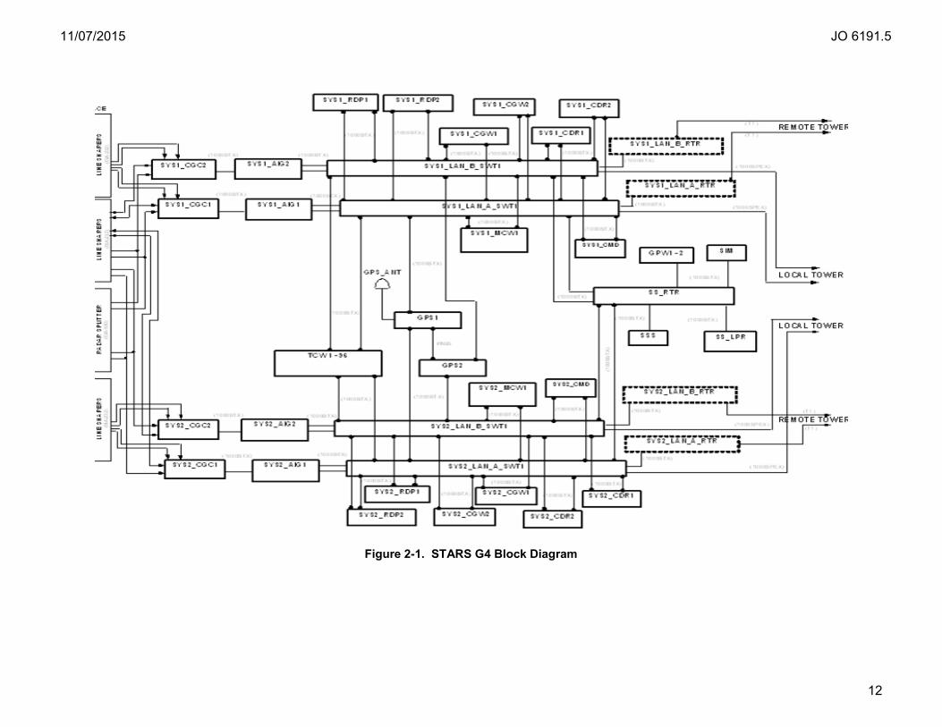
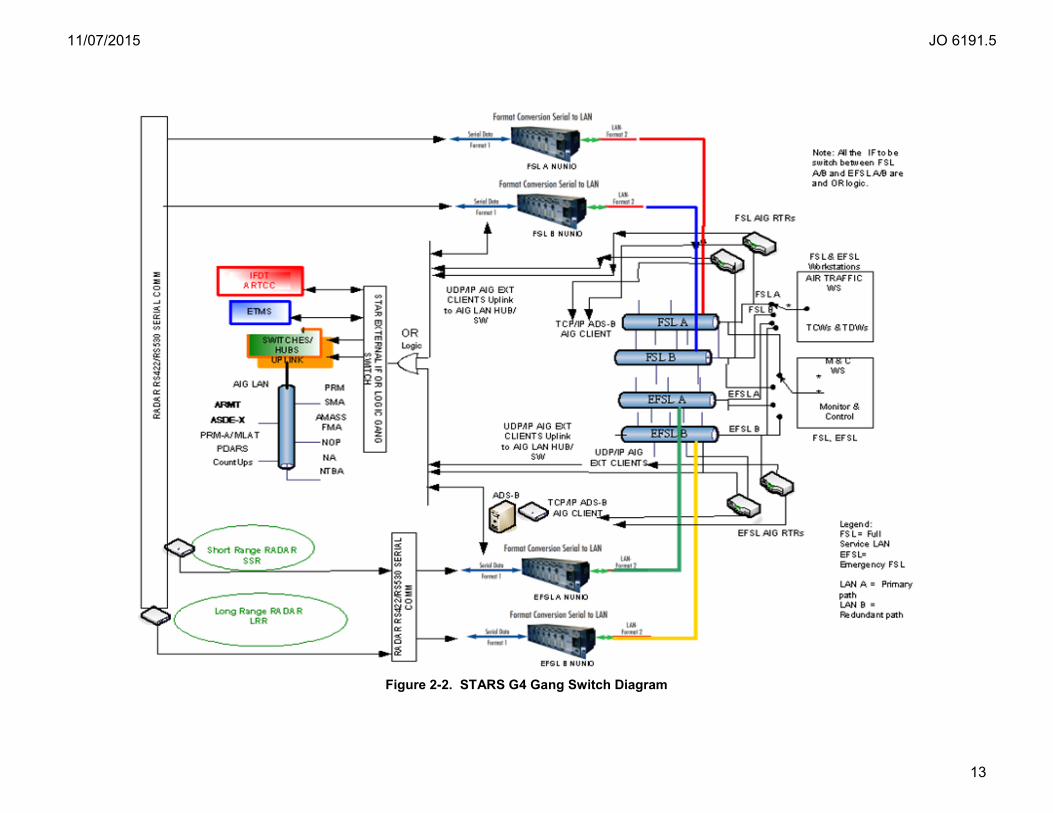
2-7. STARS Block Diagram. Respectively, Figure 2-1, STARS G4 Block Diagram; and Figure 2-2, STARS G4 Gang Switch Diagram; show typical configuration of SOS, and G4 system level switching configuration.
11/07/2015 JO 6191.5
12
Figure 2-1. STARS G4 Block Diagram
11/07/2015 JO 6191.5
13
Figure 2-2. STARS G4 Gang Switch Diagram
11/07/2015 JO 6191.5
14
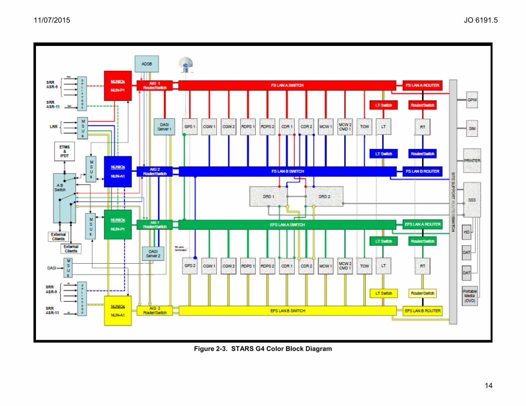
Figure 2-3. STARS G4 Color Block Diagram

11/07/2015 JO 6191.5
15
2-8. – 2-99. Reserved.
11/07/2015 JO 6191.5
16
Chapter 3. Standards and Tolerances
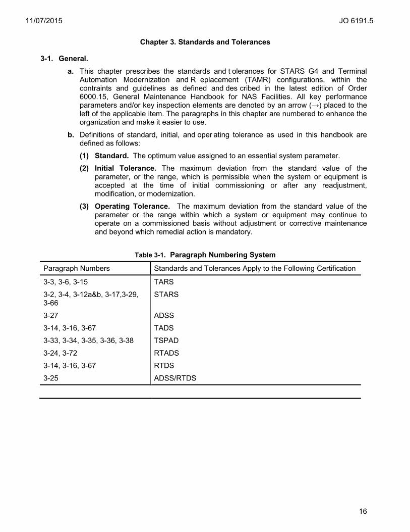
3-1. General. a. This chapter prescribes the standards and t olerances for STARS G4 and Terminal
Automation Modernization and R eplacement (TAMR) configurations, within the contraints and guidelines as defined and des cribed in the latest edition of Order 6000.15, General Maintenance Handbook for NAS Facilities. All key performance parameters and/or key inspection elements are denoted by an arrow (→) placed to the left of the applicable item. The paragraphs in this chapter are numbered to enhance the organization and make it easier to use.
b. Definitions of standard, initial, and oper ating tolerance as used in this handbook are defined as follows: (1) Standard. The optimum value assigned to an essential system parameter. (2) Initial Tolerance. The maximum deviation from the standard value of the
parameter, or the range, which is permissible when the system or equipment is accepted at the time of initial commissioning or after any readjustment, modification, or modernization.
(3) Operating Tolerance. The maximum deviation from the standard value of the parameter or the range within which a system or equipment may continue to operate on a commissioned basis without adjustment or corrective maintenance and beyond which remedial action is mandatory.
Table 3-1. Paragraph Numbering System
Paragraph Numbers Standards and Tolerances Apply to the Following Certification
3-3, 3-6, 3-15 TARS
3-2, 3-4, 3-12a&b, 3-17,3-29, 3-66
STARS
3-27 ADSS
3-14, 3-16, 3-67 TADS
3-33, 3-34, 3-35, 3-36, 3-38 TSPAD
3-24, 3-72 RTADS
3-14, 3-16, 3-67 RTDS
3-25 ADSS/RTDS
11/07/2015 JO 6191.5
17
Parameter Reference Paragraph
Standard Tolerance/Limit Initial Operating
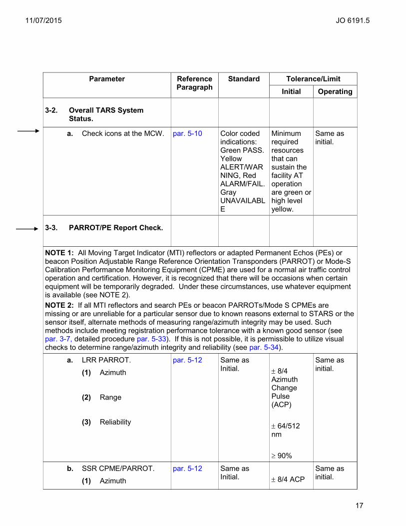
3-2. Overall TARS System Status.
a. Check icons at the MCW.
par. 5-10 Color coded indications: Green PASS. Yellow ALERT/WARNING, Red ALARM/FAIL. Gray UNAVAILABLE
Minimum required resources that can sustain the facility AT operation are green or high level yellow.
Same as initial.
3-3. PARROT/PE Report Check.
NOTE 1: All Moving Target Indicator (MTI) reflectors or adapted Permanent Echos (PEs) or beacon Position Adjustable Range Reference Orientation Transponders (PARROT) or Mode-S Calibration Performance Monitoring Equipment (CPME) are used for a normal air traffic control operation and certification. However, it is recognized that there will be occasions when certain equipment will be temporarily degraded. Under these circumstances, use whatever equipment is available (see NOTE 2). NOTE 2: If all MTI reflectors and search PEs or beacon PARROTs/Mode S CPMEs are missing or are unreliable for a particular sensor due to known reasons external to STARS or the sensor itself, alternate methods of measuring range/azimuth integrity may be used. Such methods include meeting registration performance tolerance with a known good sensor (see par. 3-7, detailed procedure par. 5-33). If this is not possible, it is permissible to utilize visual checks to determine range/azimuth integrity and reliability (see par. 5-34).
a. LRR PARROT.
(1) Azimuth
(2) Range
(3) Reliability
par. 5-12 Same as Initial.
± 8/4 Azimuth Change Pulse (ACP) ± 64/512 nm ≥ 90%
Same as initial.
b. SSR CPME/PARROT.
(1) Azimuth
par. 5-12 Same as Initial.
± 8/4 ACP
Same as initial.
11/07/2015 JO 6191.5
18
Parameter Reference Paragraph
Standard Tolerance/Limit Initial Operating
(2) Range
(3) Reliability
± 32/512 nm ≥ 90%
c. Search MTI Reflector.
(1) Azimuth
(2) Range
(3) Reliability
par. 5-12 Same as initial.
± 16/4 ACP ± 64/512 nm ≥ 80%
Same as initial.
d. Search PE.
(1) Azimuth
(2) Range
(3) Reliability
par. 5-12 Same as initial.
± 24/4 ACP ± 64/512 nm ≥ 80%
Same as initial.
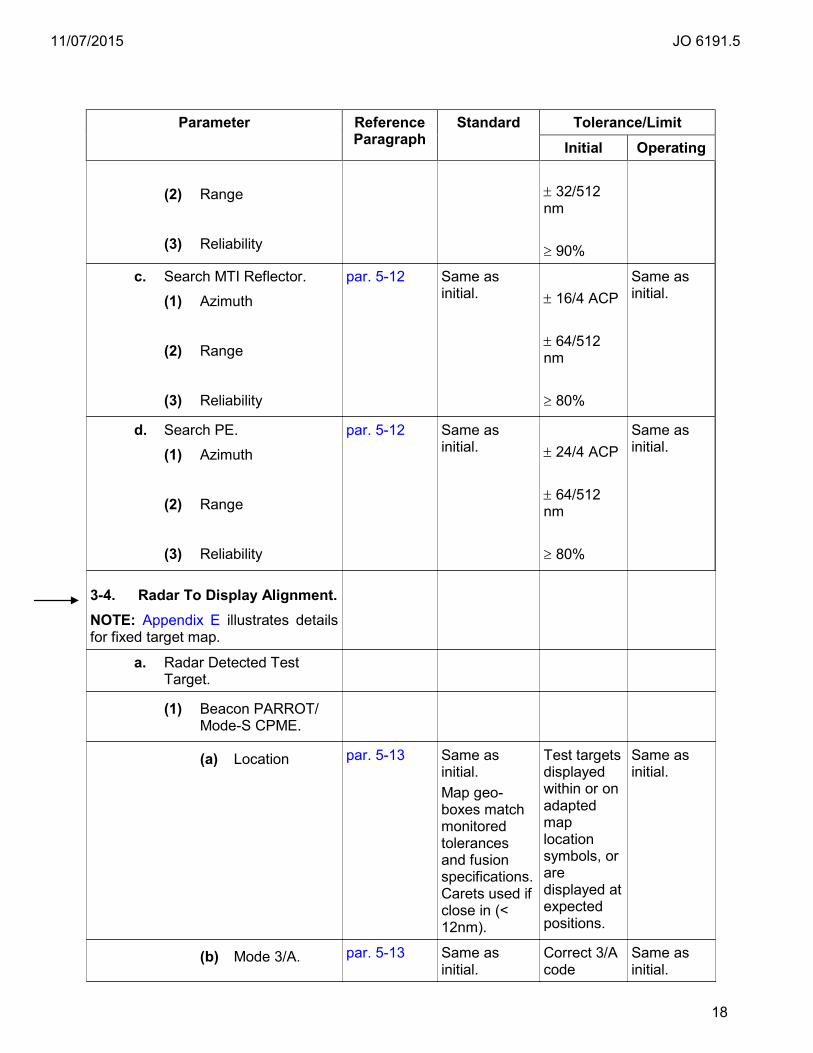
3-4. Radar To Display Alignment. NOTE: Appendix E illustrates details for fixed target map.
a. Radar Detected Test Target.
(1) Beacon PARROT/ Mode-S CPME.
(a) Location par. 5-13 Same as initial. Map geo-boxes match monitored tolerances and fusion specifications. Carets used if close in (< 12nm).
Test targets displayed within or on adapted map location symbols, or are displayed at expected positions.
Same as initial.
(b) Mode 3/A. par. 5-13 Same as initial.
Correct 3/A code
Same as initial.
11/07/2015 JO 6191.5
19
Parameter Reference Paragraph
Standard Tolerance/Limit Initial Operating
displayed.
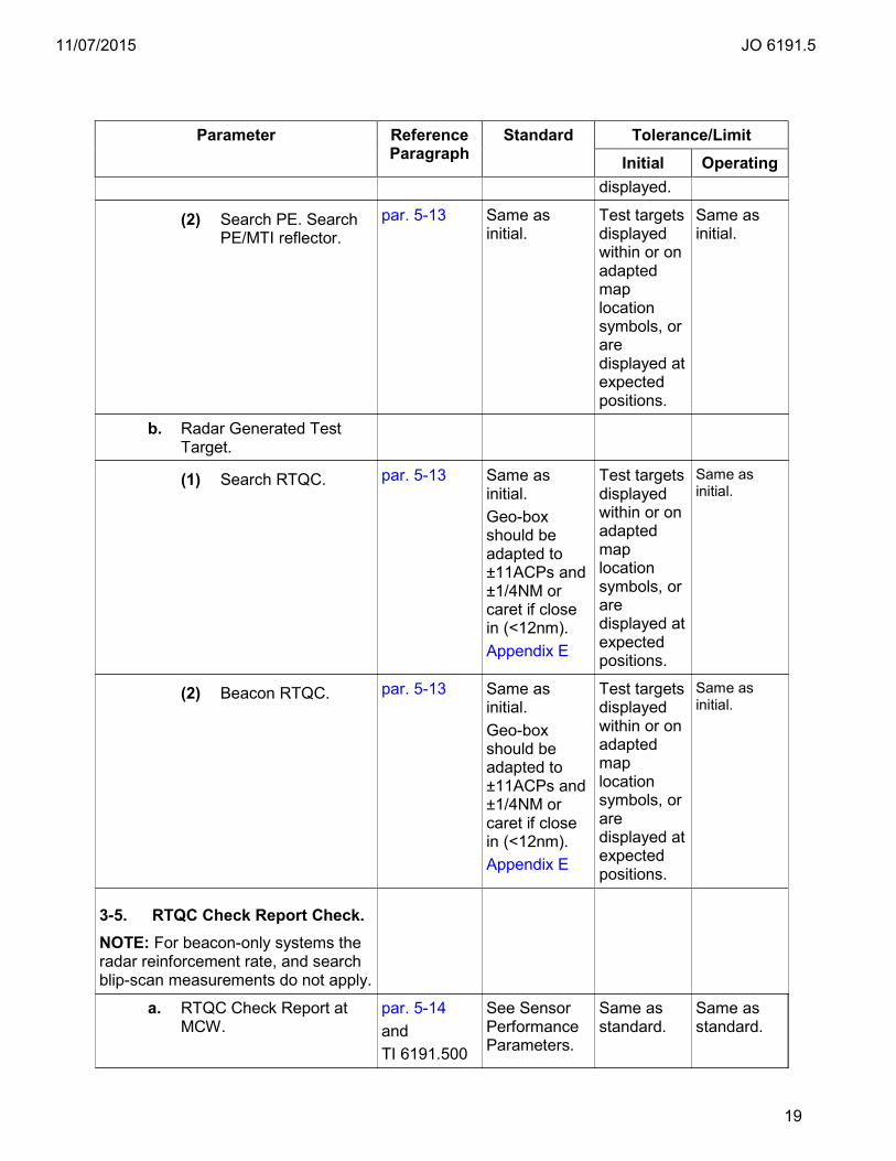
(2) Search PE. Search PE/MTI reflector.
par. 5-13 Same as initial.
Test targets displayed within or on adapted map location symbols, or are displayed at expected positions.
Same as initial.
b. Radar Generated Test Target.
(1) Search RTQC. par. 5-13 Same as initial. Geo-box should be adapted to ±11ACPs and ±1/4NM or caret if close in (<12nm). Appendix E
Test targets displayed within or on adapted map location symbols, or are displayed at expected positions.
Same as initial.
(2) Beacon RTQC. par. 5-13 Same as initial. Geo-box should be adapted to ±11ACPs and ±1/4NM or caret if close in (<12nm). Appendix E
Test targets displayed within or on adapted map location symbols, or are displayed at expected positions.
Same as initial.
3-5. RTQC Check Report Check. NOTE: For beacon-only systems the radar reinforcement rate, and search blip-scan measurements do not apply.
a. RTQC Check Report at MCW.
par. 5-14 and TI 6191.500
See Sensor Performance Parameters.
Same as standard.
Same as standard.

11/07/2015 JO 6191.5
20
Parameter Reference Paragraph
Standard Tolerance/Limit Initial Operating
par. 5-41
Sensor Performance Parameters
(1) ASR-9/11
(a) Radar Reinforcement Rate (≥)
Note 2, 5 80% Same as standard or baseline value.
Within 10% of initial.
(b) Mode 3/A Validity (≥)
Note 1 98% Same as standard or baseline value.
Within 10% of initial.
(c) Mode C Validity (≥)
Note 1 97% Same as standard or baseline value.
Within 10% of initial.
(d) Search RTQC Reliability (≥)
Note 1, 3 98% Same as standard or baseline value.
Within 10% of initial.
(e) Beacon RTQC Reliability (≥)
Note 1, 3 98% Same as standard or baseline value.
Within 10% of initial.
(f) Zero Code (<) Note 2 1% Same as standard or baseline value.
Same as standard or baseline value.
(g) Search Blip/Scan (≥)
Note 2 88% Same as standard or baseline value.
Within 10% of initial.
(h) Beacon Blip/Scan (≥)
Note 2 90% Same as standard or baseline value.
Within 10% of initial.
(i) Beacon Azimuth Split (<)
Note 2 1% Same as standard or baseline value.
Same as standard or baseline value.
(j) Range Split (<) Note 2 1% Same as standard or baseline
Same as standard or baseline
11/07/2015 JO 6191.5
21
Parameter Reference Paragraph
Standard Tolerance/Limit Initial Operating
value. value.
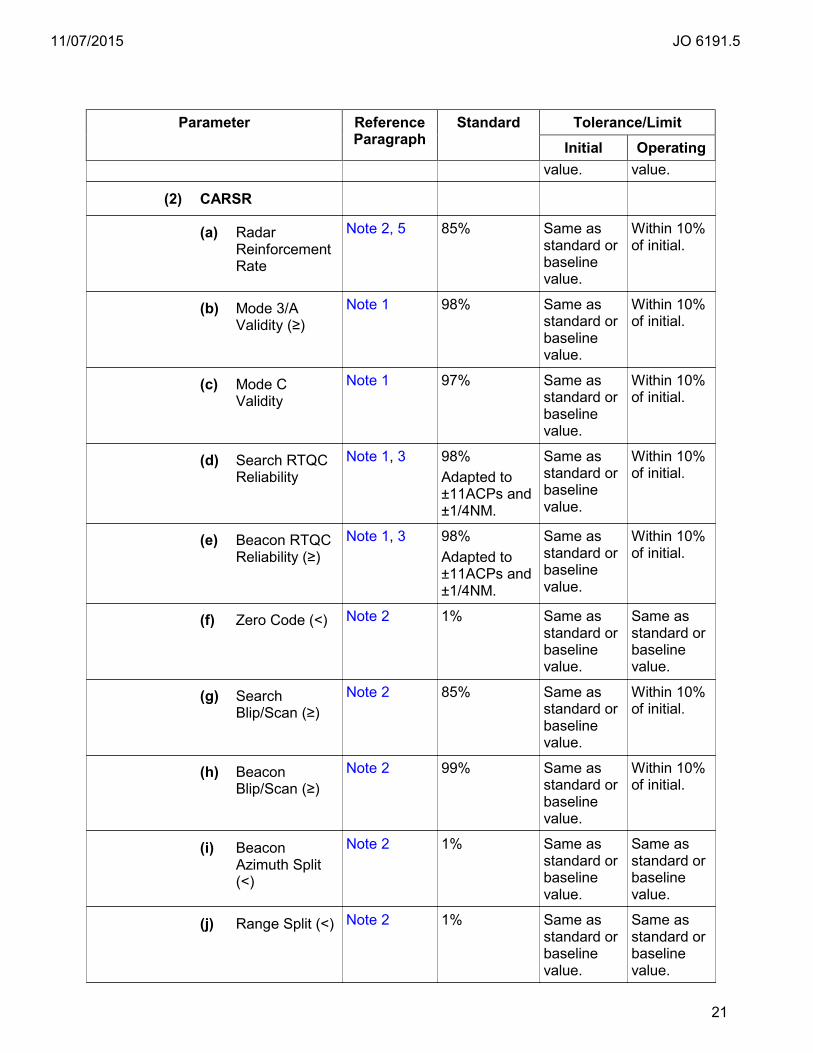
(2) CARSR
(a) Radar Reinforcement Rate
Note 2, 5 85% Same as standard or baseline value.
Within 10% of initial.
(b) Mode 3/A Validity (≥)
Note 1 98% Same as standard or baseline value.
Within 10% of initial.
(c) Mode C Validity
Note 1 97% Same as standard or baseline value.
Within 10% of initial.
(d) Search RTQC Reliability
Note 1, 3 98% Adapted to ±11ACPs and ±1/4NM.
Same as standard or baseline value.
Within 10% of initial.
(e) Beacon RTQC Reliability (≥)
Note 1, 3 98% Adapted to ±11ACPs and ±1/4NM.
Same as standard or baseline value.
Within 10% of initial.
(f) Zero Code (<) Note 2 1% Same as standard or baseline value.
Same as standard or baseline value.
(g) Search Blip/Scan (≥)
Note 2 85% Same as standard or baseline value.
Within 10% of initial.
(h) Beacon Blip/Scan (≥)
Note 2 99% Same as standard or baseline value.
Within 10% of initial.
(i) Beacon Azimuth Split (<)
Note 2 1% Same as standard or baseline value.
Same as standard or baseline value.
(j) Range Split (<) Note 2 1% Same as standard or baseline value.
Same as standard or baseline value.

11/07/2015 JO 6191.5
22
Parameter Reference Paragraph
Standard Tolerance/Limit Initial Operating
(3) ARSR-4
(a) Radar Reinforcement Rate (≥)
Note 2, 5 80% Same as standard or baseline value.
Within 10% of initial.
(b) Mode 3/A Validity (≥)
Note 1 98% Same as standard or baseline value.
Within 10% of initial.
(c) Mode C Validity (≥)
Note 1 97% Same as standard or baseline value.
Within 10% of initial.
(d) Search RTQC Reliability (≥)
Note 1, 3 98% Adapted to ±11ACPs and ±1/4NM.
Same as standard or baseline value.
Within 10% of initial.
(e) Beacon RTQC Reliability (≥)
Note 1, 3 98% Adapted to ±11ACPs and ±1/4NM.
Same as standard or baseline value.
Within 10% of initial.
(f) Zero Code (<) Note 2 1% Same as standard or baseline value.
Same as standard or baseline value.
(g) Search Blip/Scan (≥)
Note 2 92% Same as standard or baseline value.
Within 10% of initial.
(h) Beacon Blip/Scan (≥)
Note 2 96% Same as standard or baseline value.
Within 10% of initial.
(i) Beacon Azimuth Split (<)
Note 2 1% Same as standard or baseline value.
Same as standard or baseline value.
(j) Range Split (<) Note 2 1% Same as standard or baseline value.
Same as standard or baseline value.

11/07/2015 JO 6191.5
23
Parameter Reference Paragraph
Standard Tolerance/Limit Initial Operating
(4) ASR-8
(a) Radar Reinforcement Rate (≥)
Note 2, 5 80% Same as standard or baseline value.
Within 10% of initial.
(b) Mode 3/A Validity (≥)
Note 1 95% Same as standard or baseline value.
Within 10% of initial.
(c) Mode C Validity (≥)
Note 1 95% Same as standard or baseline value.
Within 10% of initial.
(d) Search RTQC Reliability (≥)
Note 1, 3 98% Adapted to ±11ACPs and ±1/4NM.
Same as standard or baseline value.
Within 10% of initial.
(e) Beacon RTQC Reliability (≥)
Note 1, 3 98% Adapted to ±11ACPs and ±1/4NM.
Same as standard or baseline value.
Within 10% of initial.
(f) Zero Code (<) Note 2 1% Same as standard or baseline value.
Same as standard or baseline value.
(g) Search Blip/Scan (≥)
Note 2 80% Same as standard or baseline value.
Within 10% of initial.
(h) Beacon Blip/Scan (≥)
Note 2 90% Same as standard or baseline value.
Within 10% of initial.
(i) Beacon Azimuth Split (<)
Note 2 1% Same as standard or baseline value.
Same as standard or baseline value.
(j) Range Split (<) Note 2 1% Same as standard or baseline value.
Same as standard or baseline value.
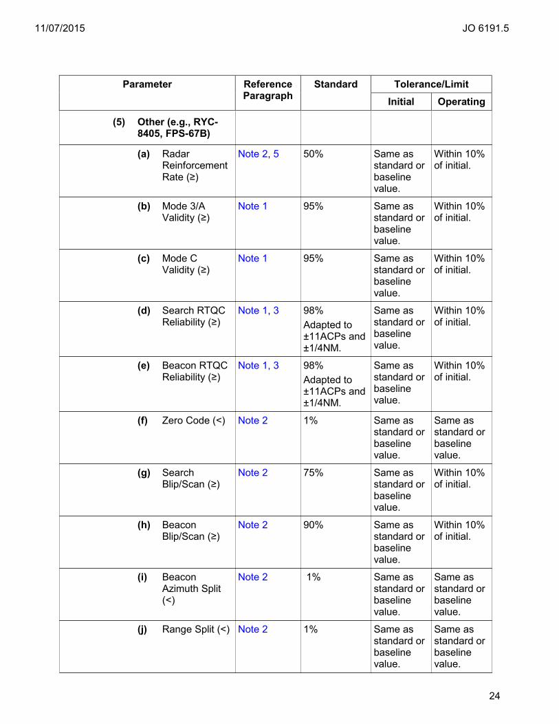
11/07/2015 JO 6191.5
24
Parameter Reference Paragraph
Standard Tolerance/Limit Initial Operating
(5) Other (e.g., RYC-8405, FPS-67B)
(a) Radar Reinforcement Rate (≥)
Note 2, 5 50% Same as standard or baseline value.
Within 10% of initial.
(b) Mode 3/A Validity (≥)
Note 1 95% Same as standard or baseline value.
Within 10% of initial.
(c) Mode C Validity (≥)
Note 1 95% Same as standard or baseline value.
Within 10% of initial.
(d) Search RTQC Reliability (≥)
Note 1, 3 98% Adapted to ±11ACPs and ±1/4NM.
Same as standard or baseline value.
Within 10% of initial.
(e) Beacon RTQC Reliability (≥)
Note 1, 3 98% Adapted to ±11ACPs and ±1/4NM.
Same as standard or baseline value.
Within 10% of initial.
(f) Zero Code (<) Note 2 1% Same as standard or baseline value.
Same as standard or baseline value.
(g) Search Blip/Scan (≥)
Note 2 75% Same as standard or baseline value.
Within 10% of initial.
(h) Beacon Blip/Scan (≥)
Note 2 90% Same as standard or baseline value.
Within 10% of initial.
(i) Beacon Azimuth Split (<)
Note 2 1% Same as standard or baseline value.
Same as standard or baseline value.
(j) Range Split (<) Note 2 1% Same as standard or baseline value.
Same as standard or baseline value.
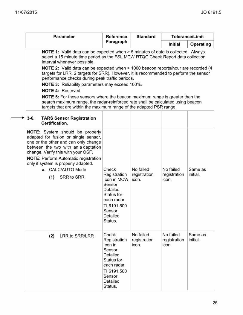
11/07/2015 JO 6191.5
25
Parameter Reference Paragraph
Standard Tolerance/Limit Initial Operating
NOTE 1: Valid data can be expected when > 5 minutes of data is collected. Always select a 15 minute time period as the FSL MCW RTQC Check Report data collection interval whenever possible. NOTE 2: Valid data can be expected when > 1000 beacon reports/hour are recorded (4 targets for LRR, 2 targets for SRR). However, it is recommended to perform the sensor performance checks during peak traffic periods. NOTE 3: Reliability parameters may exceed 100%. NOTE 4: Reserved. NOTE 5: For those sensors where the beacon maximum range is greater than the search maximum range, the radar-reinforced rate shall be calculated using beacon targets that are within the maximum range of the adapted PSR range.
3-6. TARS Sensor Registration Certification.
NOTE: System should be properly adapted for fusion or single sensor, one or the other and can only change between the two with an a daptation change. Verify this with your OSF. NOTE: Perform Automatic registration only if system is properly adapted.
a. CALC/AUTO Mode
(1) SRR to SRR
Check Registration Icon in MCW Sensor Detailed Status for each radar. TI 6191.500 Sensor Detailed Status.
No failed registration icon.
No failed registration icon.
Same as initial.
(2) LRR to SRR/LRR Check Registration Icon in Sensor Detailed Status for each radar. TI 6191.500 Sensor Detailed Status.
No failed registration icon.
No failed registration icon.
Same as initial.
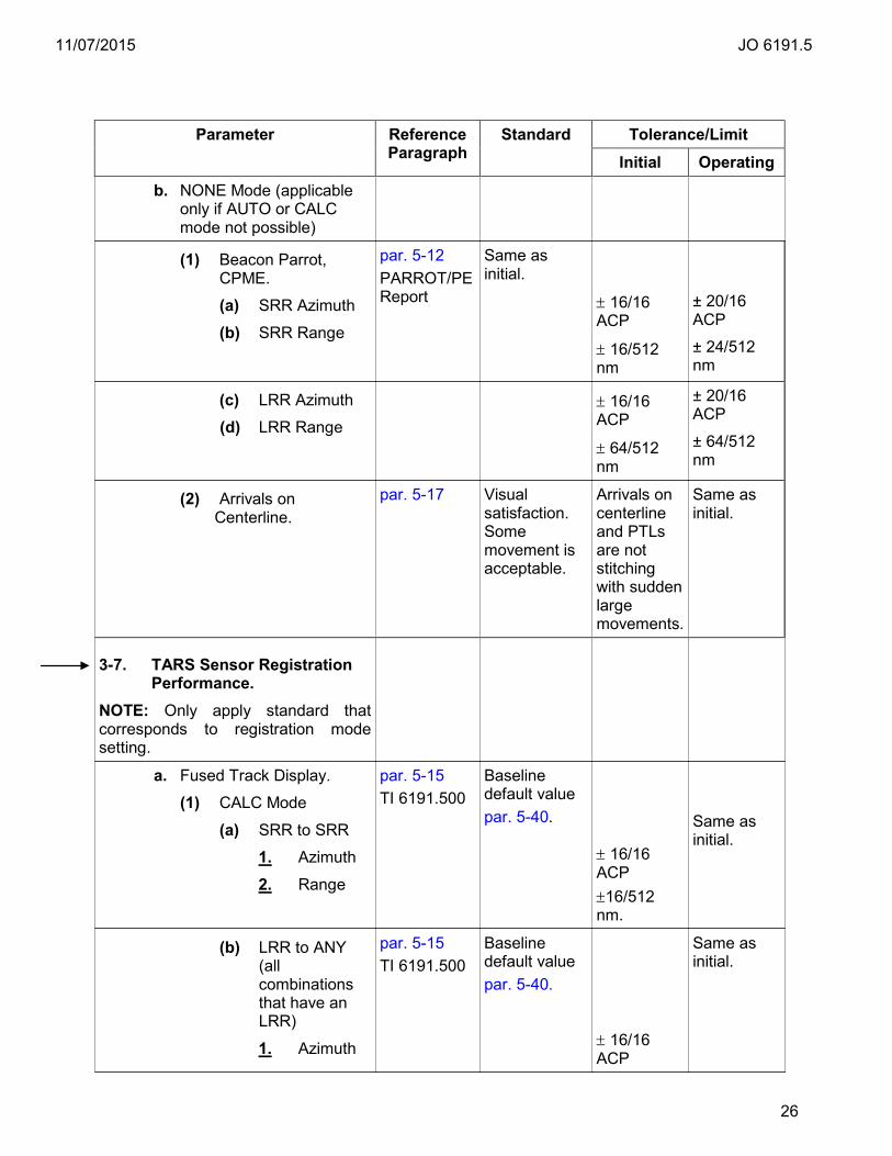
11/07/2015 JO 6191.5
26
Parameter Reference Paragraph
Standard Tolerance/Limit Initial Operating
b. NONE Mode (applicable only if AUTO or CALC mode not possible)
(1) Beacon Parrot, CPME.
(a) SRR Azimuth
(b) SRR Range
par. 5-12 PARROT/PE Report
Same as initial.
± 16/16 ACP
± 16/512 nm
± 20/16 ACP
± 24/512 nm
(c) LRR Azimuth
(d) LRR Range
± 16/16 ACP
± 64/512 nm
± 20/16 ACP
± 64/512 nm
(2) Arrivals on Centerline.
par. 5-17 Visual satisfaction. Some movement is acceptable.
Arrivals on centerline and PTLs are not stitching with sudden large movements.
Same as initial.
3-7. TARS Sensor Registration Performance.
NOTE: Only apply standard that corresponds to registration mode setting.
a. Fused Track Display.
(1) CALC Mode
(a) SRR to SRR
1. Azimuth
2. Range
par. 5-15 TI 6191.500
Baseline default value par. 5-40.
± 16/16 ACP ±16/512 nm.
Same as initial.
(b) LRR to ANY (all combinations that have an LRR)
1. Azimuth
par. 5-15 TI 6191.500
Baseline default value par. 5-40.
± 16/16 ACP
Same as initial.
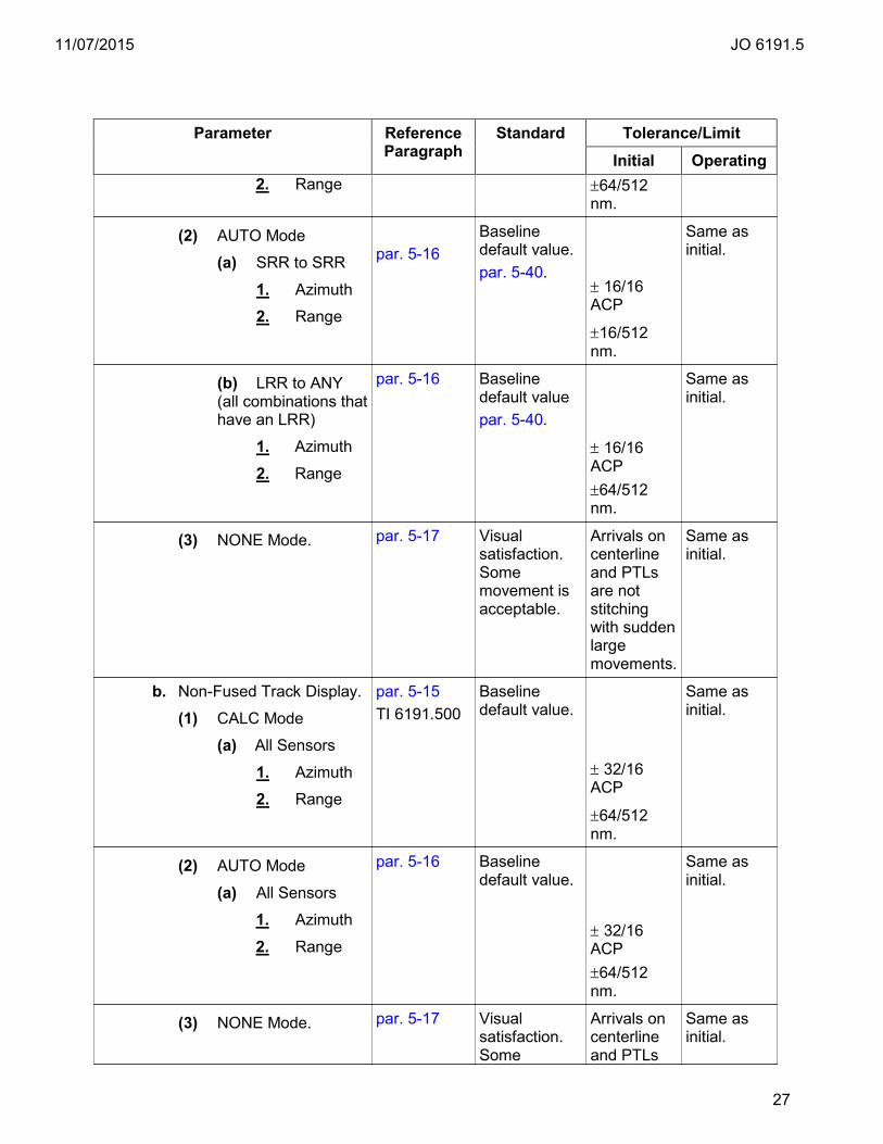
11/07/2015 JO 6191.5
27
Parameter Reference Paragraph
Standard Tolerance/Limit Initial Operating
2. Range ±64/512 nm.
(2) AUTO Mode
(a) SRR to SRR
1. Azimuth
2. Range
par. 5-16
Baseline default value. par. 5-40.
± 16/16 ACP
±16/512 nm.
Same as initial.
(b) LRR to ANY (all combinations that have an LRR)
1. Azimuth
2. Range
par. 5-16 Baseline default value par. 5-40.
± 16/16 ACP ±64/512 nm.
Same as initial.
(3) NONE Mode.
par. 5-17 Visual satisfaction. Some movement is acceptable.
Arrivals on centerline and PTLs are not stitching with sudden large movements.
Same as initial.
b. Non-Fused Track Display.
(1) CALC Mode
(a) All Sensors
1. Azimuth
2. Range
par. 5-15 TI 6191.500
Baseline default value.
± 32/16 ACP
±64/512 nm.
Same as initial.
(2) AUTO Mode
(a) All Sensors
1. Azimuth
2. Range
par. 5-16
Baseline default value.
± 32/16 ACP ±64/512 nm.
Same as initial.
(3) NONE Mode. par. 5-17 Visual satisfaction. Some
Arrivals on centerline and PTLs
Same as initial.
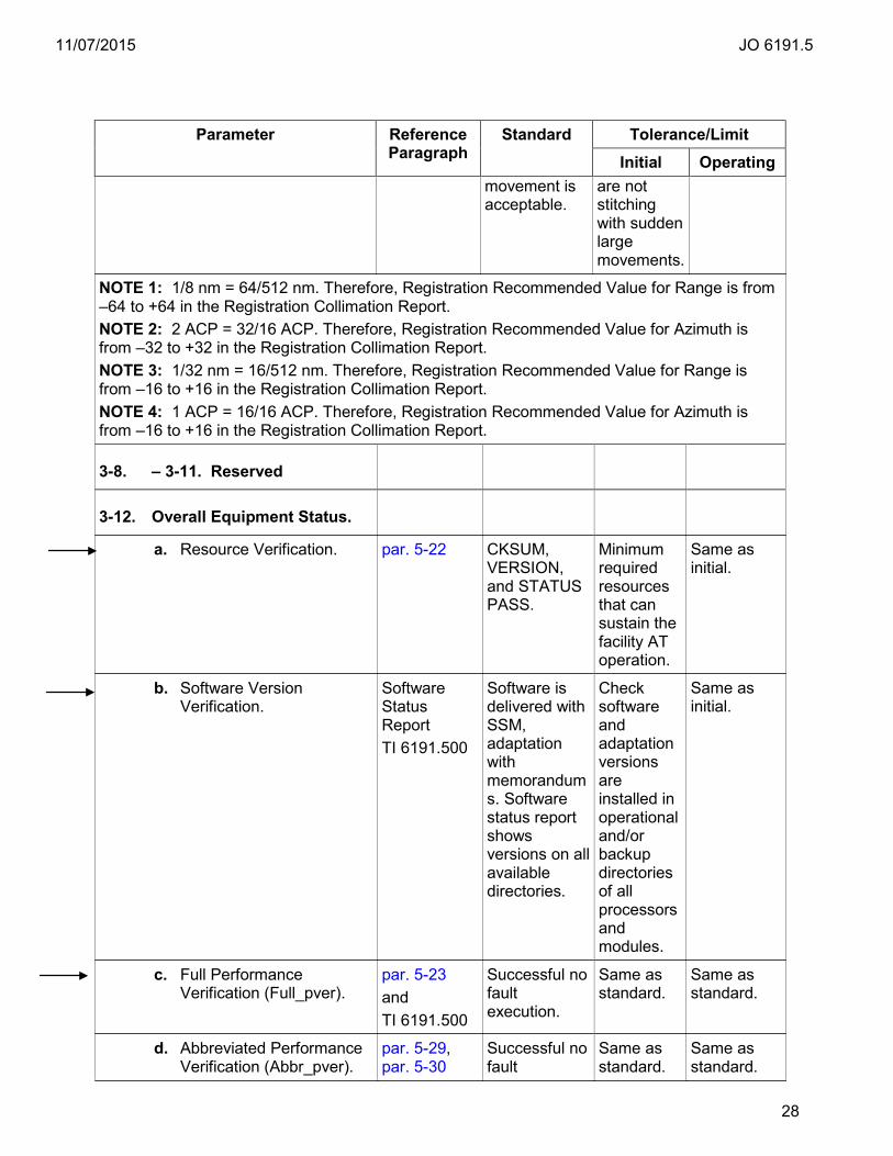
11/07/2015 JO 6191.5
28
Parameter Reference Paragraph
Standard Tolerance/Limit Initial Operating
movement is acceptable.
are not stitching with sudden large movements.
NOTE 1: 1/8 nm = 64/512 nm. Therefore, Registration Recommended Value for Range is from –64 to +64 in the Registration Collimation Report. NOTE 2: 2 ACP = 32/16 ACP. Therefore, Registration Recommended Value for Azimuth is from –32 to +32 in the Registration Collimation Report. NOTE 3: 1/32 nm = 16/512 nm. Therefore, Registration Recommended Value for Range is from –16 to +16 in the Registration Collimation Report. NOTE 4: 1 ACP = 16/16 ACP. Therefore, Registration Recommended Value for Azimuth is from –16 to +16 in the Registration Collimation Report.
3-8. – 3-11. Reserved
3-12. Overall Equipment Status.
a. Resource Verification. par. 5-22 CKSUM, VERSION, and STATUS PASS.
Minimum required resources that can sustain the facility AT operation.
Same as initial.
b. Software Version Verification.
Software Status Report TI 6191.500
Software is delivered with SSM, adaptation with memorandums. Software status report shows versions on all available directories.
Check software and adaptation versions are installed in operational and/or backup directories of all processors and modules.
Same as initial.
c. Full Performance Verification (Full_pver).
par. 5-23 and TI 6191.500
Successful no fault execution.
Same as standard.
Same as standard.
d. Abbreviated Performance Verification (Abbr_pver).
par. 5-29, par. 5-30
Successful no fault
Same as standard.
Same as standard.

11/07/2015 JO 6191.5
29
Parameter Reference Paragraph
Standard Tolerance/Limit Initial Operating
Targets of opportunity.
execution all pass no rejections or lack of user complaint (qualified observer).
3-13. Single Service Resource Redundancy.
a. Configure service level to utilize the standby resources.
par. 5-24 Successful no fault execution.
Same as standard.
Same as standard.
3-14. FSL/EFSL Availability.
a. If FSL and EFSL are utilized by AT personnel for operational use or in standby operational use.
TI 6191.500 par. 5-25
Enabled and indicating OK/OK.
Same as standard.
Same as standard.
b. If EFSL is released to TOS or DoD Radar Maintenance for maintenance, positions in test partition, or in cases of FSL failure.
TI 6191.500 par. 5-25
Disabled and indicating OK/NA from FS or NA/OK from EFS.
Same as standard.
Same as standard.
3-15. Flight Data Processing Certification.
a. Inter-Facility Data Transfer (IFDT) Input/Output Check.
par. 5-28 IFDT connection is established.
Same as standard.
Same as standard.
3-16. System Status Alert Color Check.
par. 5-27 Inverted red delta is displayed.
Same as standard.
Same as standard.
3-17. Summarization Report Check.
par. 5-18
a. Track Storage Capacity. Average of 1 minute intervals over a one hour period.
≥ 0% Average.
Same as initial.
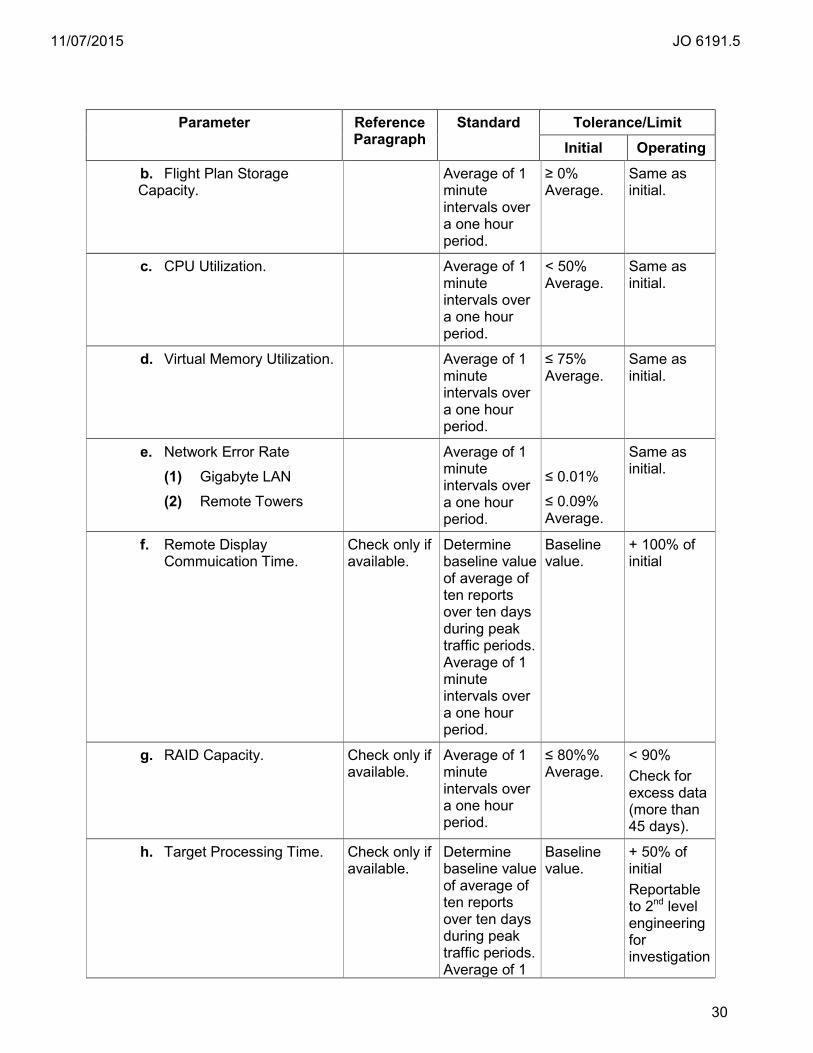
11/07/2015 JO 6191.5
30
Parameter Reference Paragraph
Standard Tolerance/Limit Initial Operating
b. Flight Plan Storage Capacity.
Average of 1 minute intervals over a one hour period.
≥ 0% Average.
Same as initial.
c. CPU Utilization. Average of 1 minute intervals over a one hour period.
< 50% Average.
Same as initial.
d. Virtual Memory Utilization. Average of 1 minute intervals over a one hour period.
≤ 75% Average.
Same as initial.
e. Network Error Rate
(1) Gigabyte LAN
(2) Remote Towers
Average of 1 minute intervals over a one hour period.
≤ 0.01%
≤ 0.09% Average.
Same as initial.
f. Remote Display Commuication Time.
Check only if available.
Determine baseline value of average of ten reports over ten days during peak traffic periods. Average of 1 minute intervals over a one hour period.
Baseline value.
+ 100% of initial
g. RAID Capacity. Check only if available.
Average of 1 minute intervals over a one hour period.
≤ 80%% Average.
< 90% Check for excess data (more than 45 days).
h. Target Processing Time. Check only if available.
Determine baseline value of average of ten reports over ten days during peak traffic periods. Average of 1
Baseline value.
+ 50% of initial Reportable to 2nd level engineering for investigation
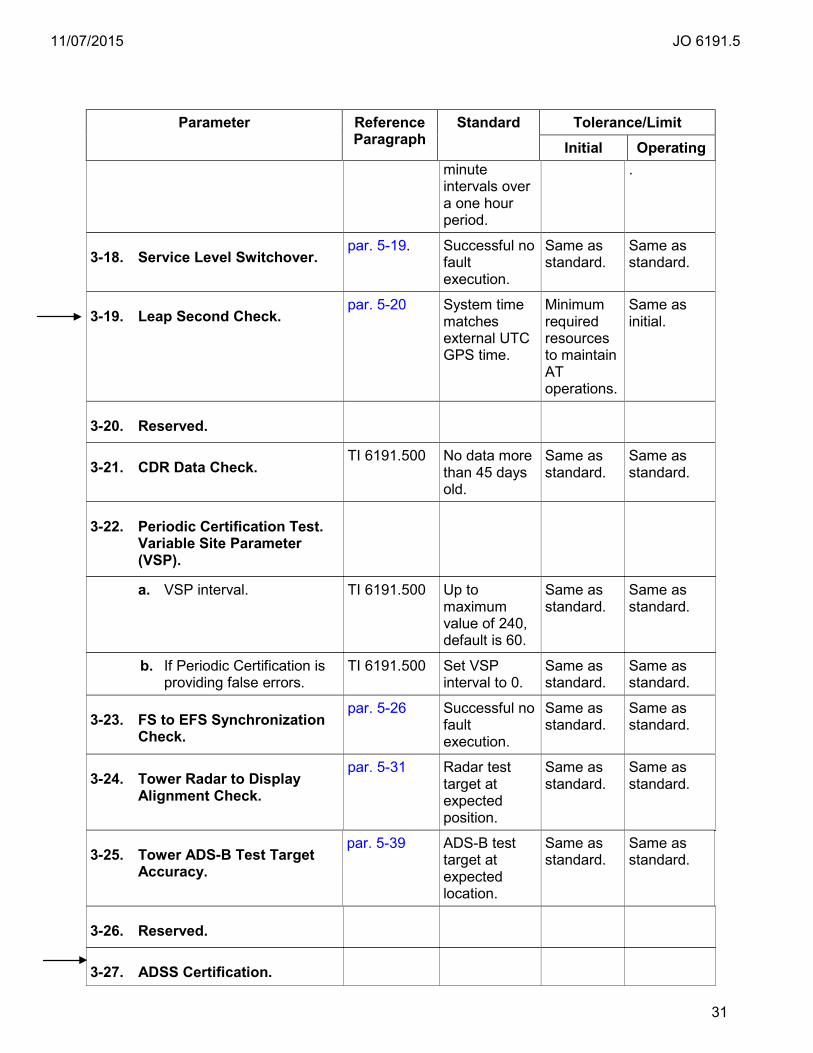
11/07/2015 JO 6191.5
31
Parameter Reference Paragraph
Standard Tolerance/Limit Initial Operating
minute intervals over a one hour period.
.
3-18. Service Level Switchover. par. 5-19. Successful no
fault execution.
Same as standard.
Same as standard.
3-19. Leap Second Check. par. 5-20 System time
matches external UTC GPS time.
Minimum required resources to maintain AT operations.
Same as initial.
3-20. Reserved.
3-21. CDR Data Check. TI 6191.500 No data more
than 45 days old.
Same as standard.
Same as standard.
3-22. Periodic Certification Test. Variable Site Parameter (VSP).
a. VSP interval. TI 6191.500 Up to maximum value of 240, default is 60.
Same as standard.
Same as standard.
b. If Periodic Certification is providing false errors.
TI 6191.500 Set VSP interval to 0.
Same as standard.
Same as standard.
3-23. FS to EFS Synchronization Check.
par. 5-26 Successful no fault execution.
Same as standard.
Same as standard.
3-24. Tower Radar to Display Alignment Check.
par. 5-31 Radar test target at expected position.
Same as standard.
Same as standard.
3-25. Tower ADS-B Test Target Accuracy.
par. 5-39 ADS-B test target at expected location.
Same as standard.
Same as standard.
3-26. Reserved.
3-27. ADSS Certification.
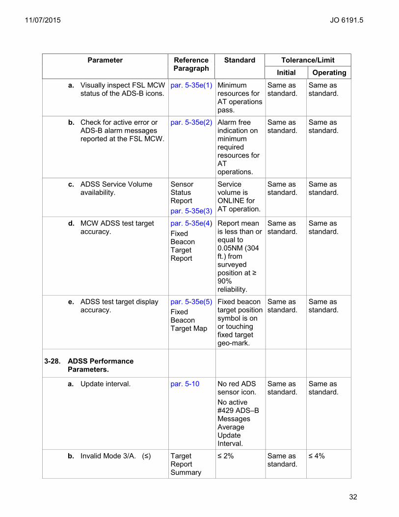
11/07/2015 JO 6191.5
32
Parameter Reference Paragraph
Standard Tolerance/Limit Initial Operating
a. Visually inspect FSL MCW status of the ADS-B icons.
par. 5-35e(1) Minimum resources for AT operations pass.
Same as standard.
Same as standard.
b. Check for active error or ADS-B alarm messages reported at the FSL MCW.
par. 5-35e(2) Alarm free indication on minimum required resources for AT operations.
Same as standard.
Same as standard.
c. ADSS Service Volume availability.
Sensor Status Report par. 5-35e(3)
Service volume is ONLINE for AT operation.
Same as standard.
Same as standard.
d. MCW ADSS test target accuracy.
par. 5-35e(4) Fixed Beacon Target Report
Report mean is less than or equal to 0.05NM (304 ft.) from surveyed position at ≥ 90% reliability.
Same as standard.
Same as standard.
e. ADSS test target display accuracy.
par. 5-35e(5) Fixed Beacon Target Map
Fixed beacon target position symbol is on or touching fixed target geo-mark.
Same as standard.
Same as standard.
3-28. ADSS Performance Parameters.
a. Update interval. par. 5-10 No red ADS sensor icon. No active #429 ADS–B Messages Average Update Interval.
Same as standard.
Same as standard.
b. Invalid Mode 3/A. (≤) Target Report Summary
≤ 2% Same as standard.
≤ 4%

11/07/2015 JO 6191.5
33
Parameter Reference Paragraph
Standard Tolerance/Limit Initial Operating
par. 5-36
c. Invalid Atltitude. (≤) Target Report Summary par. 5-36
≤ 3% Same as standard.
≤ 5%.
d. Discarded Target Reports. Target Report Summary par. 5-36
≤ 10% or of baseline value when available.
Same as standard.
≤ 20%.
e. TOAp Age Greater Than Adapted.
Target Report Summary par. 5-36
≤ 5% of ADS-B Geodetic Reports or baseline value when available.
Same as standard.
≤ 10%.
f. TOAp Age Less Than Adapted.
Target Report Summary par. 5-36
≤ 5% of ADS-B Geodetic Reports or baseline value when available.
Same as standard.
≤ 10%.
g. TOMR Age Greater Than Adapted.
Target Report Summary par. 5-36
≤ 5% of ADS-B Geodetic Reports or baseline value when available.
Same as standard.
≤ 10%.
h. TOMR Age Less Than Adapted.
Target Report Summary par. 5-36
≤ 5% of ADS-B Geodetic Reports or baseline value when available.
Same as standard.
≤ 10%.
3-29. ADSS Performance Verification.
par. 5-38 Successful no fault execution.
Same as standard.
Same as standard.
3-30. – 3-31. Reserved.
3-32. TSPAD MCW Icon Check.
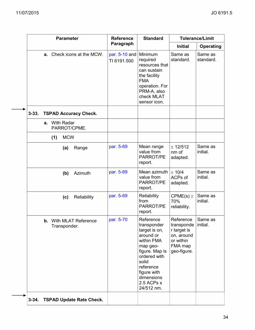
11/07/2015 JO 6191.5
34
Parameter Reference Paragraph
Standard Tolerance/Limit Initial Operating
a. Check icons at the MCW. par. 5-10 and TI 6191.500
Minimum required resources that can sustain the facility FMA operation. For PRM-A, also check MLAT sensor icon.
Same as standard.
Same as standard.
3-33. TSPAD Accuracy Check.
a. With Radar PARROT/CPME.
(1) MCW
(a) Range par. 5-69 Mean range value from PARROT/PE report.
± 12/512 nm of adapted.
Same as initial.
(b) Azimuth par. 5-69 Mean azimuth value from PARROT/PE report.
± 10/4 ACPs of adapted.
Same as initial.
(c) Reliability par. 5-69 Reliability from PARROT/PE report.
CPME(s) ≥ 70% reliability.
Same as initial.
b. With MLAT Reference Transponder.
par. 5-70 Reference transponder target is on, around or within FMA map geo-figure. Map is ordered with solid reference figure with dimensions 2.5 ACPs x 24/512 nm.
Reference transponder target is on, around or within FMA map geo-figure.
Same as initial.
3-34. TSPAD Update Rate Check.

11/07/2015 JO 6191.5
35
Parameter Reference Paragraph
Standard Tolerance/Limit Initial Operating
a. Radar. par. 5-73 Measure time of 10 target updates.
The target update rate shall be equal to or less than 4.8 seconds in track mode.
Same as initial.
b. MLAT. par. 5-78 MLAT RefTran updates should be equal to or exceed listed values.
# of MLAT RefTran msgs from Target Summary Report is within tolerance in Table 5-5.
Same as initial.
3-35. TSPAD Sensor Availability.
a. (Mode S/Monopulse radar) Operational Status.
par. 5-65
The Mode S operating in mono-pulse mode is required for full FMA service certification. The Mode S operating in interim beacon interrogator (IBI) mode is required for partial FMA service certification.
Same as standard.
Same as standard.
b. MLAT Availabile for sites that have PRM-A.
par. 5-75 Same as initial.
MLAT available.
Same as initial.
3-36. TSPAD Display Entry and Display Processing.
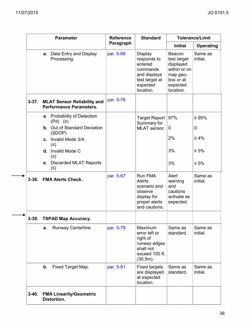
11/07/2015 JO 6191.5
36
Parameter Reference Paragraph
Standard Tolerance/Limit Initial Operating
a. Data Entry and Display Processing.
par. 5-68 Display responds to entered commands and displays test target at expected location.
Beacon test target displayed within or on map geo-box or at expected location.
Same as initial.
3-37. MLAT Sensor Reliability and Performance Parameters.
par. 5-76
a. Probability of Detection (Pd) (≥)
b. Out of Standard Deviation (SDOP)
c. Invalid Mode 3/A (≤)
d. Invalid Mode C (≤)
e. Discarded MLAT Reports (≤)
Target Report Summary for MLAT sensor.
97%
0
2%
3%
3%
≥ 95%
0
≤ 4%
≤ 5%
≤ 5%
3-38. FMA Alerts Check. par. 5-67 Run FMA
Alerts scenario and observe display for proper alerts and cautions.
Alert warning and cautions activate as expected.
Same as initial.
3-39. TSPAD Map Accuracy.
a. Runway Centerline. par. 5-79 Maximum error left or right of runway edges shall not exceed 100 ft. (30.5m).
Same as standard.
Same as initial.
b. Fixed Target Map. par. 5-81 Fixed targets are displayed at expected location.
Same as standard.
Same as initial.
3-40. FMA Linearity/Geometric Distortion.
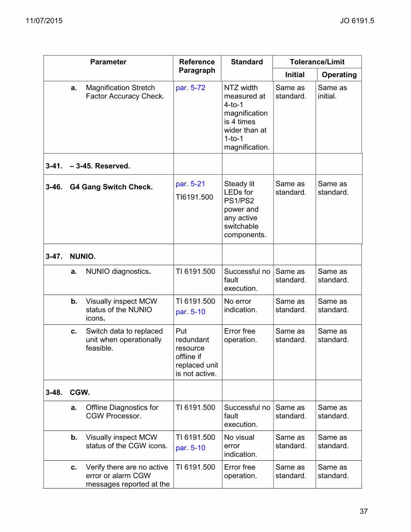
11/07/2015 JO 6191.5
37
Parameter Reference Paragraph
Standard Tolerance/Limit Initial Operating
a. Magnification Stretch Factor Accuracy Check.
par. 5-72 NTZ width measured at 4-to-1 magnification is 4 times wider than at 1-to-1 magnification.
Same as standard.
Same as initial.
3-41. – 3-45. Reserved.
3-46. G4 Gang Switch Check. par. 5-21
TI6191.500
Steady lit LEDs for PS1/PS2 power and any active switchable components.
Same as standard.
Same as standard.
3-47. NUNIO.
a. NUNIO diagnostics. TI 6191.500 Successful no fault execution.
Same as standard.
Same as standard.
b. Visually inspect MCW status of the NUNIO icons.
TI 6191.500 par. 5-10
No error indication.
Same as standard.
Same as standard.
c. Switch data to replaced unit when operationally feasible.
Put redundant resource offline if replaced unit is not active.
Error free operation.
Same as standard.
Same as standard.
3-48. CGW.
a. Offline Diagnostics for CGW Processor.
TI 6191.500 Successful no fault execution.
Same as standard.
Same as standard.
b. Visually inspect MCW status of the CGW icons.
TI 6191.500 par. 5-10
No visual error indication.
Same as standard.
Same as standard.
c. Verify there are no active error or alarm CGW messages reported at the
TI 6191.500 Error free operation.
Same as standard.
Same as standard.

11/07/2015 JO 6191.5
38
Parameter Reference Paragraph
Standard Tolerance/Limit Initial Operating
MCW.
d. Network Information System Plus (NIS+) check.
par. 5-32 Successful no fault execution.
Same as standard.
Same as standard.
3-49. RDP.
a. Visually inspect MCW status of the RDP icons.
TI 6191.500 par. 5-10
No visual error indication.
Same as standard.
Same as standard.
b. Offline Diagnostics for RDP Processor.
TI 6191.500 Successful no fault execution.
Same as standard.
Same as standard.
c. Verify there are no active error or alarm RDP messages reported at the MCW.
TI 6191.500 Error free operation.
Same as standard.
Same as standard.
d. Network Information System Plus (NIS+) check.
par. 5-32 Successful no fault execution.
Same as standard.
Same as standard.
3-50. TCW.
a. Offline Diagnostics for TCW Processor.
TI 6191.500 Successful no fault execution.
Same as standard.
Same as standard.
b. Verify there are no active error or alarm TCW messages reported at the MCW or failed Icon.
TI 6191.500 par. 5-10
Error free operation.
Same as standard.
Same as standard.
c. Network Information System Plus (NIS+) check.
par. 5-32 Successful no fault execution.
Same as standard.
Same as standard.
d. Verify individual speakers.
par. 3-67 Audible Alarm Test and adjust speaker volume from the DCB.
Successful no fault execution.
Same as standard.
Same as standard.
e. Check Display SSA. OK/OK availability. No WKST FAIL,
Visual verification.
Same as standard.
Same as standard.

11/07/2015 JO 6191.5
39
Parameter Reference Paragraph
Standard Tolerance/Limit Initial Operating
OVERLOAD or red banner.
f. System status alert color check.
par. 5-27 Alert color observed.
Same as standard.
Same as standard.
g. Display updates as expected.
Clock and targets (if available) update. Rotate through single-sensor, fused or multi-mode if latter two are applicable.)
Successful no fault execution or lack of user complaint.
Same as standard.
Same as standard.
h. Abbreviated Performance Verification Check (1 of 3 options).
Successful no fault execution or lack of user complaint.
Same as standard.
Same as standard.
(1) From MCW. par. 5-29 par. 3-12d Same as standard.
Same as standard.
(2) From Position. par. 5-30 par. 3-12d Same as standard.
Same as standard.
(3) Targets of Opportunity.
Aural and visual observation of air traffic safety alerts if available.
Visual and aural satisfaction or lack of user complaint (qualified observer).
Same as standard.
Same as standard.
3-51. TDW.
a. Coordinate with a qualified user to visually inspect MCW status of the TDW icons.
TI 6191.500 par. 5-10
No visual error indication.
Same as standard.
Same as standard.
b. Coordinate with a qualified user to execute a offline Diagnostics for Processor.
TI 6191.500 Successful no fault execution.
Same as standard.
Same as standard.
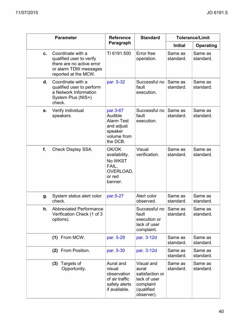
11/07/2015 JO 6191.5
40
Parameter Reference Paragraph
Standard Tolerance/Limit Initial Operating
c. Coordinate with a qualified user to verify there are no active error or alarm TDW messages reported at the MCW.
TI 6191.500 Error free operation.
Same as standard.
Same as standard.
d. Coordinate with a qualified user to perform a Network Information System Plus (NIS+) check.
par. 5-32 Successful no fault execution.
Same as standard.
Same as standard.
e. Verify individual speakers.
par.3-67 Audible Alarm Test and adjust speaker volume from the DCB.
Successful no fault execution.
Same as standard.
Same as standard.
f. Check Display SSA. OK/OK availability. No WKST FAIL, OVERLOAD, or red banner.
Visual verification.
Same as standard.
Same as standard.
g. System status alert color check.
par.5-27 Alert color observed.
Same as standard.
Same as standard.
h. Abbreviated Performance Verification Check (1 of 3 options).
Successful no fault execution or lack of user complaint.
Same as standard.
Same as standard.
(1) From MCW. par. 5-29 par. 3-12d Same as standard.
Same as standard.
(2) From Position. par. 5-30 par. 3-12d Same as standard.
Same as standard.
(3) Targets of Opportunity.
Aural and visual observation of air traffic safety alerts if available.
Visual and aural satisfaction or lack of user complaint (qualified observer).
Same as standard.
Same as standard.
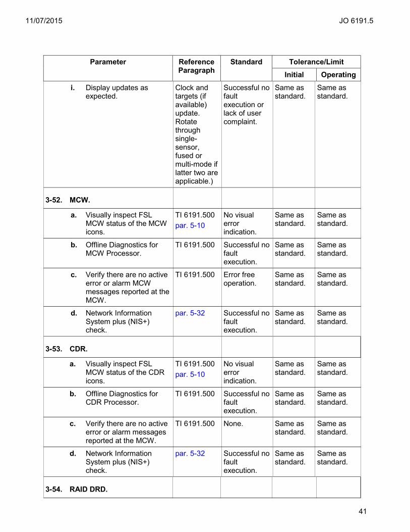
11/07/2015 JO 6191.5
41
Parameter Reference Paragraph
Standard Tolerance/Limit Initial Operating
i. Display updates as expected.
Clock and targets (if available) update. Rotate through single-sensor, fused or multi-mode if latter two are applicable.)
Successful no fault execution or lack of user complaint.
Same as standard.
Same as standard.
3-52. MCW.
a. Visually inspect FSL MCW status of the MCW icons.
TI 6191.500 par. 5-10
No visual error indication.
Same as standard.
Same as standard.
b. Offline Diagnostics for MCW Processor.
TI 6191.500 Successful no fault execution.
Same as standard.
Same as standard.
c. Verify there are no active error or alarm MCW messages reported at the MCW.
TI 6191.500 Error free operation.
Same as standard.
Same as standard.
d. Network Information System plus (NIS+) check.
par. 5-32 Successful no fault execution.
Same as standard.
Same as standard.
3-53. CDR.
a. Visually inspect FSL MCW status of the CDR icons.
TI 6191.500 par. 5-10
No visual error indication.
Same as standard.
Same as standard.
b. Offline Diagnostics for CDR Processor.
TI 6191.500 Successful no fault execution.
Same as standard.
Same as standard.
c. Verify there are no active error or alarm messages reported at the MCW.
TI 6191.500 None. Same as standard.
Same as standard.
d. Network Information System plus (NIS+) check.
par. 5-32 Successful no fault execution.
Same as standard.
Same as standard.
3-54. RAID DRD.
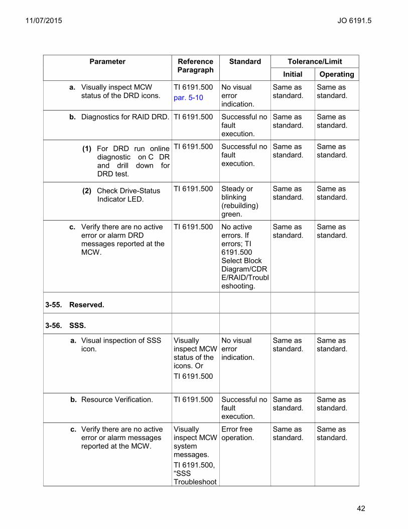
11/07/2015 JO 6191.5
42
Parameter Reference Paragraph
Standard Tolerance/Limit Initial Operating
a. Visually inspect MCW status of the DRD icons.
TI 6191.500 par. 5-10
No visual error indication.
Same as standard.
Same as standard.
b. Diagnostics for RAID DRD. TI 6191.500
Successful no fault execution.
Same as standard.
Same as standard.
(1) For DRD run online diagnostic on C DR and drill down for DRD test.
TI 6191.500 Successful no fault execution.
Same as standard.
Same as standard.
(2) Check Drive-Status Indicator LED.
TI 6191.500 Steady or blinking (rebuilding) green.
Same as standard.
Same as standard.
c. Verify there are no active error or alarm DRD messages reported at the MCW.
TI 6191.500 No active errors. If errors; TI 6191.500 Select Block Diagram/CDRE/RAID/Troubleshooting.
Same as standard.
Same as standard.
3-55. Reserved.
3-56. SSS.
a. Visual inspection of SSS icon.
Visually inspect MCW status of the icons. Or TI 6191.500
No visual error indication.
Same as standard.
Same as standard.
b. Resource Verification. TI 6191.500 Successful no fault execution.
Same as standard.
Same as standard.
c. Verify there are no active error or alarm messages reported at the MCW.
Visually inspect MCW system messages. TI 6191.500, “SSS Troubleshoot
Error free operation.
Same as standard.
Same as standard.
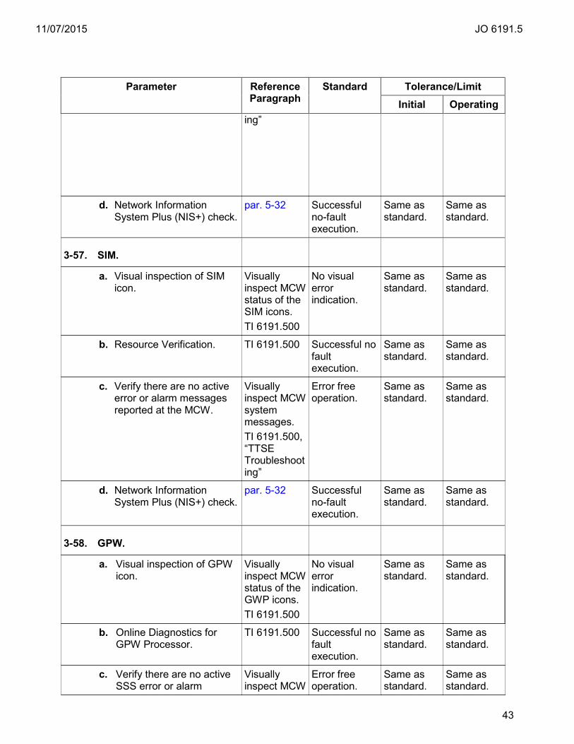
11/07/2015 JO 6191.5
43
Parameter Reference Paragraph
Standard Tolerance/Limit Initial Operating
ing”
d. Network Information System Plus (NIS+) check.
par. 5-32 Successful no-fault execution.
Same as standard.
Same as standard.
3-57. SIM.
a. Visual inspection of SIM icon.
Visually inspect MCW status of the SIM icons. TI 6191.500
No visual error indication.
Same as standard.
Same as standard.
b. Resource Verification. TI 6191.500 Successful no fault execution.
Same as standard.
Same as standard.
c. Verify there are no active error or alarm messages reported at the MCW.
Visually inspect MCW system messages. TI 6191.500, “TTSE Troubleshooting”
Error free operation.
Same as standard.
Same as standard.
d. Network Information System Plus (NIS+) check.
par. 5-32 Successful no-fault execution.
Same as standard.
Same as standard.
3-58. GPW.
a. Visual inspection of GPW icon.
Visually inspect MCW status of the GWP icons. TI 6191.500
No visual error indication.
Same as standard.
Same as standard.
b. Online Diagnostics for GPW Processor.
TI 6191.500 Successful no fault execution.
Same as standard.
Same as standard.
c. Verify there are no active SSS error or alarm
Visually inspect MCW
Error free operation.
Same as standard.
Same as standard.
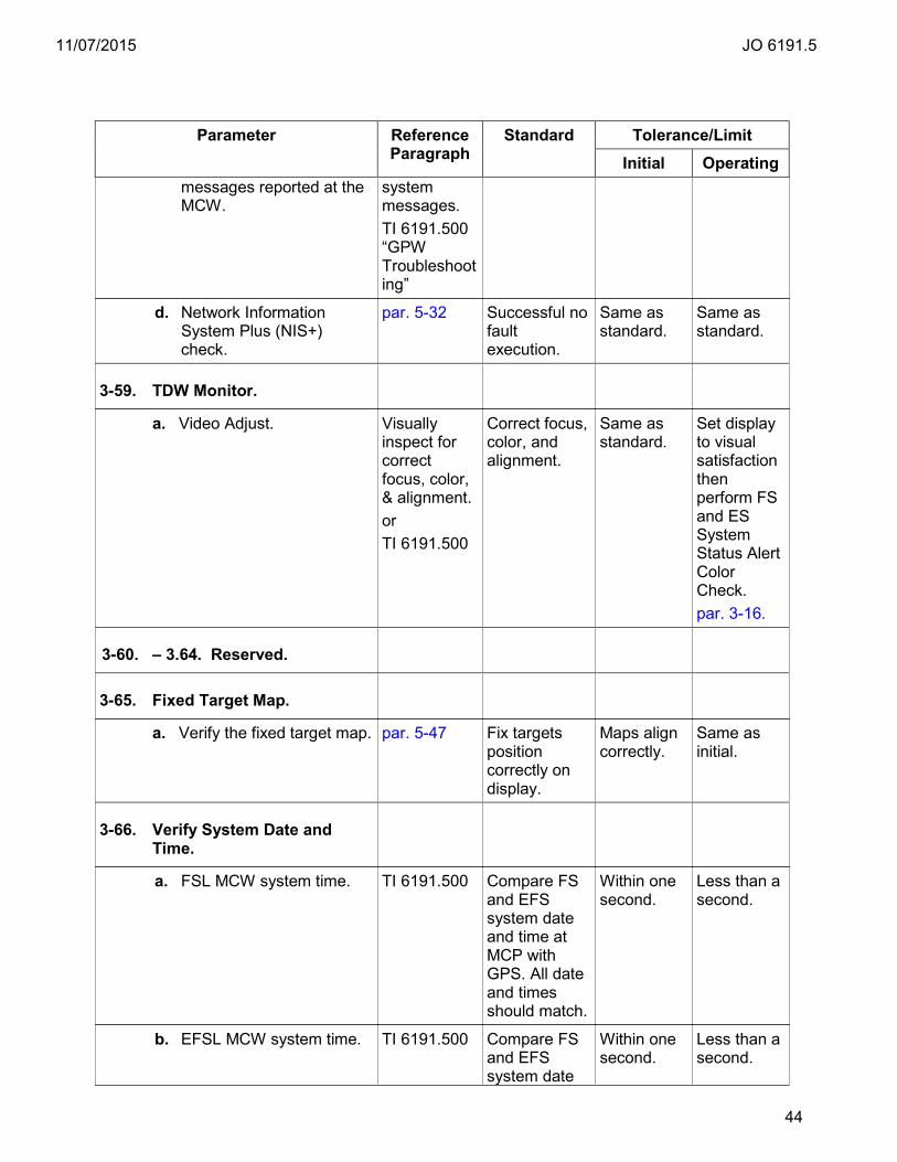
11/07/2015 JO 6191.5
44
Parameter Reference Paragraph
Standard Tolerance/Limit Initial Operating
messages reported at the MCW.
system messages. TI 6191.500 “GPW Troubleshooting”
d. Network Information System Plus (NIS+) check.
par. 5-32 Successful no fault execution.
Same as standard.
Same as standard.
3-59. TDW Monitor.
a. Video Adjust. Visually inspect for correct focus, color, & alignment. or TI 6191.500
Correct focus, color, and alignment.
Same as standard.
Set display to visual satisfaction then perform FS and ES System Status Alert Color Check. par. 3-16.
3-60. – 3.64. Reserved.
3-65. Fixed Target Map.
a. Verify the fixed target map. par. 5-47 Fix targets position correctly on display.
Maps align correctly.
Same as initial.
3-66. Verify System Date and Time.
a. FSL MCW system time. TI 6191.500 Compare FS and EFS system date and time at MCP with GPS. All date and times should match.
Within one second.
Less than a second.
b. EFSL MCW system time. TI 6191.500 Compare FS and EFS system date
Within one second.
Less than a second.
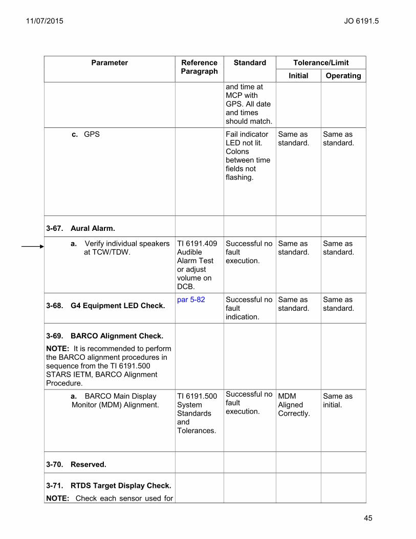
11/07/2015 JO 6191.5
45
Parameter Reference Paragraph
Standard Tolerance/Limit Initial Operating
and time at MCP with GPS. All date and times should match.
c. GPS Fail indicator LED not lit. Colons between time fields not flashing.
Same as standard.
Same as standard.
3-67. Aural Alarm.
a. Verify individual speakers at TCW/TDW.
TI 6191.409 Audible Alarm Test or adjust volume on DCB.
Successful no fault execution.
Same as standard.
Same as standard.
3-68. G4 Equipment LED Check. par 5-82 Successful no
fault indication.
Same as standard.
Same as standard.
3-69. BARCO Alignment Check. NOTE: It is recommended to perform the BARCO alignment procedures in sequence from the TI 6191.500 STARS IETM, BARCO Alignment Procedure.
a. BARCO Main Display Monitor (MDM) Alignment.
TI 6191.500 System Standards and Tolerances.
Successful no fault execution.
MDM Aligned Correctly.
Same as initial.
3-70. Reserved.
3-71. RTDS Target Display Check. NOTE: Check each sensor used for
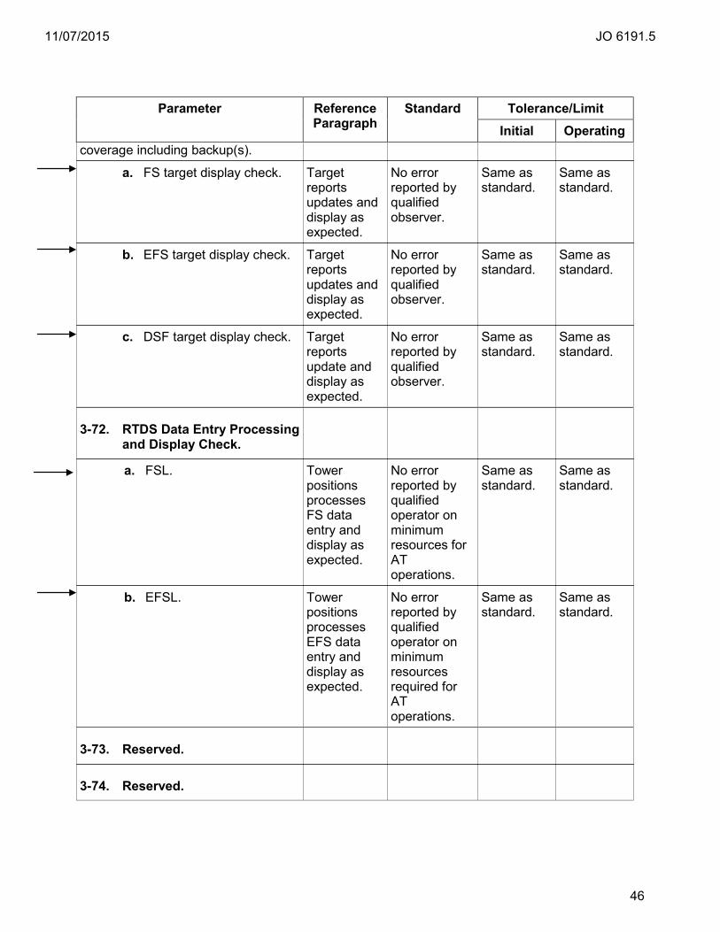
11/07/2015 JO 6191.5
46
Parameter Reference Paragraph
Standard Tolerance/Limit Initial Operating
coverage including backup(s).
a. FS target display check.
Target reports updates and display as expected.
No error reported by qualified observer.
Same as standard.
Same as standard.
b. EFS target display check.
Target reports updates and display as expected.
No error reported by qualified observer.
Same as standard.
Same as standard.
c. DSF target display check. Target reports update and display as expected.
No error reported by qualified observer.
Same as standard.
Same as standard.
3-72. RTDS Data Entry Processing and Display Check.
a. FSL.
Tower positions processes FS data entry and display as expected.
No error reported by qualified operator on minimum resources for AT operations.
Same as standard.
Same as standard.
b. EFSL. Tower positions processes EFS data entry and display as expected.
No error reported by qualified operator on minimum resources required for AT operations.
Same as standard.
Same as standard.
3-73. Reserved.
3-74. Reserved.

11/07/2015 JO 6191.5
47
Chapter 4. Periodic Maintenance
4-1. General. a. This chapter establishes all maintenance activities that are required for STARS
equipment on a periodic, recurring basis, and the schedules for their accomplishment. The chapter is divided into two sections. The first section identifies the performance checks (i.e., tests, measurements, and observations) of normal operating controls and functions for STARS, which are necessary to determine whether operation is within established tolerances/limits. The second section identifies other tasks which are necessary to prevent deterioration and/or ensure reliable operation of STARS.
b. Order 6000.15 requires that certain routine and general maintenance tasks be completed on all NAS hardware. Refer to Order 6000.15 for a list of routine maintenance requirements and other maintenance requirements.
c. All test equipment must be maintained in proper operating condition. Refer to paragraph 1-16 of this handbook for references to test equipment. Refer to the latest edition of Order 6200.4, Test Equipment Management Handbook for further information on test equipment.
d. Refer to Order 6000.15 for the periodic maintenance intervals and their tolerances.
e. Refer to Order 6191.2, STARS Security Handbook, for STARS security periodic intervals and tolerances.
Section 1. FSL/SYS1 Performance Checks
Performance Checks Reference Paragraph Standards &
Tolerances Maintenance Procedures
4-2. Daily.
a. At the FSL MCW, check icons for proper indications.
par. 3-2a par. 5-10
b. PARROT/PE Report Check. Print or save report. par. 3-3 par. 5-12
c. Radar to Display Alignment Check. par. 3-4 par. 5-13
d. RTQC Check Report. Print or save report. par. 3-5 par. 5-14
e. Registration Certification. NOTE: Only perform one task that corresponds to registration operating mode setting.
par. 3-6a par. 3-6b
Calc/Auto Mode Check registration icon. None Mode, par. 5-17
f. Registration Performance. Print or save report. Registration/Collimation report once during peak traffic period. For NONE mode ensure a
par. 3-7 Calc, par. 5-15 Auto, par. 5-16

11/07/2015 JO 6191.5
48
Section 1. FSL/SYS1 Performance Checks
Performance Checks Reference Paragraph Standards &
Tolerances Maintenance Procedures
PARROT/PE report is available. NOTE: Only perform one task that corresponds to registration operating mode setting.
g. Check Inter-Facility data transmission. par. 3-15 par. 5-28
h. Verify system date and time. par. 3-66 Compare FS and EFS system date and time at MCP with GPS1 and GPS2. All date and times should match. No flashing colon or fail indicator on GPS faceplate.
i. Check for requisite As Required tasks. FSL Other
par. 4-11 par. 4-65
j. Delete any CDR data more than 45 days old.
(1) For sites with a Options/FS Delete Expired Data selection.
par. 3-21 Verify displayed data then press this selection.
k. G4 STARS (except S4 software baseline sites) ensure EFSL/SYS2 IFDT is offline or display synchronization will not work properly. Put IFDT online from the SYS2 MCW if EFSL/SYS2 is operational.
ESFL/SYS2 IFDT icon is GREY/OFFLINE on standby service level MCW.
Select Interface control/IFDT on SYS2 MCW, select IF site and take both feeds offline.
l. G4 Equipment LED Check par. 3-68 par. 5-82
4-3. Weekly.
a. Complete Resource Verification Test. Print or save report.
par. 3-12a par. 5-22
b. At the FSL MCW, check the Periodic Certification Test Variable Site Parameter (VSP) interval.
par. 3-22 TI 6191.500
c. RAID/DRD Redunancy and Integrity. par. 3-54 TI 6191.500
4-4. Biweekly.
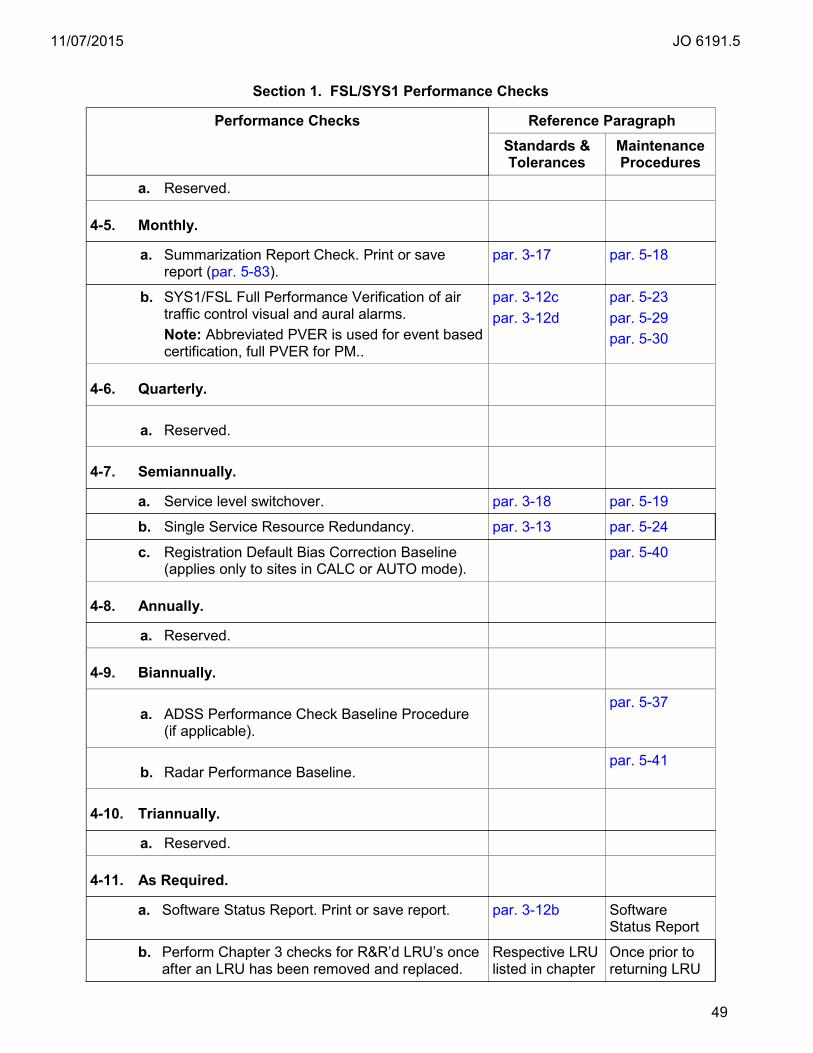
11/07/2015 JO 6191.5
49
Section 1. FSL/SYS1 Performance Checks
Performance Checks Reference Paragraph Standards &
Tolerances Maintenance Procedures
a. Reserved.
4-5. Monthly.
a. Summarization Report Check. Print or save report (par. 5-83).
par. 3-17 par. 5-18
b. SYS1/FSL Full Performance Verification of air traffic control visual and aural alarms. Note: Abbreviated PVER is used for event based certification, full PVER for PM..
par. 3-12c par. 3-12d
par. 5-23 par. 5-29 par. 5-30
4-6. Quarterly.
a. Reserved.
4-7. Semiannually.
a. Service level switchover. par. 3-18 par. 5-19
b. Single Service Resource Redundancy. par. 3-13 par. 5-24
c. Registration Default Bias Correction Baseline (applies only to sites in CALC or AUTO mode).
par. 5-40
4-8. Annually.
a. Reserved.
4-9. Biannually.
a. ADSS Performance Check Baseline Procedure (if applicable).
par. 5-37
b. Radar Performance Baseline. par. 5-41
4-10. Triannually.
a. Reserved.
4-11. As Required.
a. Software Status Report. Print or save report. par. 3-12b Software Status Report
b. Perform Chapter 3 checks for R&R’d LRU’s once after an LRU has been removed and replaced.
Respective LRU listed in chapter
Once prior to returning LRU

11/07/2015 JO 6191.5
50
Section 1. FSL/SYS1 Performance Checks
Performance Checks Reference Paragraph Standards &
Tolerances Maintenance Procedures
3. to service.
c. Service level switchover. par. 3-18 par. 5-19
4-12. – 4-15. Reserved.
a. Reserved.
Section 2. EFSL/SYS2 Performance Checks
Performance Checks Reference Paragraph Standards &
Tolerances Maintenance Procedures
4-16. Daily.
a. At the EFSL MCW, check icons for proper indications.
par. 3-2a par. 5-10
b. PARROT/PE Report Check. Print or save report. par. 3-3 par. 5-12
c. Radar to Display Alignment Check. par. 3-4 par. 5-13
d. RTQC Check Report. Print or save report. par. 3-5 par. 5-14
e. Registration Certification.
NOTE: Only perform one task that corresponds to registration operating mode setting.
par. 3-6a par. 3-6b
Calc/Auto Mode Check registration icon. None Mode, par. 5-17
f. Registration Performance. Print or save Registration/Collimation report once during peak traffic period. For NONE mode ensure a PARROT/PE report is printed or saved.
NOTE: Only perform one task that corresponds to registration mode setting.
par. 3-7 Calc, par. 5-15 Auto, par. 5-16
g. Check Inter-Facility data transmission. par. 3-15 par. 5-28. Only if EFS/SYS2 is active operational system.
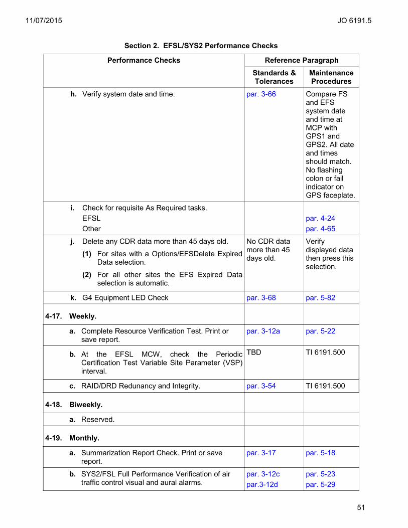
11/07/2015 JO 6191.5
51
Section 2. EFSL/SYS2 Performance Checks
Performance Checks Reference Paragraph Standards &
Tolerances Maintenance Procedures
h. Verify system date and time. par. 3-66 Compare FS and EFS system date and time at MCP with GPS1 and GPS2. All date and times should match. No flashing colon or fail indicator on GPS faceplate.
i. Check for requisite As Required tasks. EFSL Other
par. 4-24 par. 4-65
j. Delete any CDR data more than 45 days old.
(1) For sites with a Options/EFSDelete Expired Data selection.
(2) For all other sites the EFS Expired Data selection is automatic.
No CDR data more than 45 days old.
Verify displayed data then press this selection.
k. G4 Equipment LED Check par. 3-68 par. 5-82
4-17. Weekly.
a. Complete Resource Verification Test. Print or save report.
par. 3-12a par. 5-22
b. At the EFSL MCW, check the Periodic Certification Test Variable Site Parameter (VSP) interval.
TBD TI 6191.500
c. RAID/DRD Redunancy and Integrity. par. 3-54 TI 6191.500
4-18. Biweekly.
a. Reserved.
4-19. Monthly.
a. Summarization Report Check. Print or save report.
par. 3-17 par. 5-18
b. SYS2/FSL Full Performance Verification of air traffic control visual and aural alarms.
par. 3-12c par.3-12d
par. 5-23 par. 5-29

11/07/2015 JO 6191.5
52
Section 2. EFSL/SYS2 Performance Checks
Performance Checks Reference Paragraph Standards &
Tolerances Maintenance Procedures
Note: Abbreviated PVER is used for event based certification, full PVER for PM.
par. 5-30
4-20. Quarterly.
a. Reserved.
4-21. Semiannually.
a. Service Level Switchover. par. 3-18 par. 5-19
b. Single Service Resource Redundancy. par. 3-13 par. 5-24
4-22. Annually.
a. Reserved.
4-23. Triannually.
a. Reserved.
4-24. As Required.
a. Software Status Report. Print or save report. par. 3-12b Software Status Report.
b. Perform chapter 3 checks for R&R’d LRU’s once after an LRU has been removed and replaced.
Respective LRU listed in chapter 3.
Once prior to returning LRU to service.
Section 3. TADS Performance Checks
Performance Checks Reference Paragraph Standards &
Tolerances Maintenance Procedures
4-25. Daily.
a. FSL/EFSL System status alert color check. par.3-16 par. 5-27
b. Check FSL/EFSL Availablity. par. 3-14 par, 5-25
c. Verify individual speakers on each of the TCWs. par. 3-67 TI 6191.409 Audible Alarm Test.
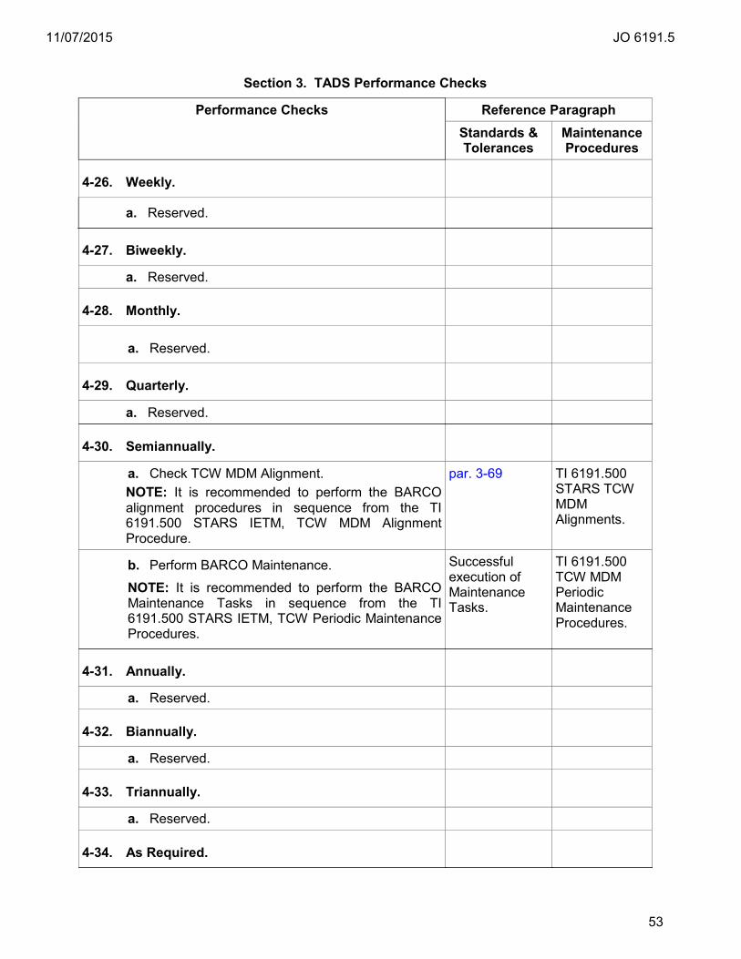
11/07/2015 JO 6191.5
53
Section 3. TADS Performance Checks
Performance Checks Reference Paragraph Standards &
Tolerances Maintenance Procedures
4-26. Weekly.
a. Reserved.
4-27. Biweekly.
a. Reserved.
4-28. Monthly.
a. Reserved.
4-29. Quarterly.
a. Reserved.
4-30. Semiannually.
a. Check TCW MDM Alignment. NOTE: It is recommended to perform the BARCO alignment procedures in sequence from the TI 6191.500 STARS IETM, TCW MDM Alignment Procedure.
par. 3-69 TI 6191.500 STARS TCW MDM Alignments.
b. Perform BARCO Maintenance. NOTE: It is recommended to perform the BARCO Maintenance Tasks in sequence from the TI 6191.500 STARS IETM, TCW Periodic Maintenance Procedures.
Successful execution of Maintenance Tasks.
TI 6191.500 TCW MDM Periodic Maintenance Procedures.
4-31. Annually.
a. Reserved.
4-32. Biannually.
a. Reserved.
4-33. Triannually.
a. Reserved.
4-34. As Required.
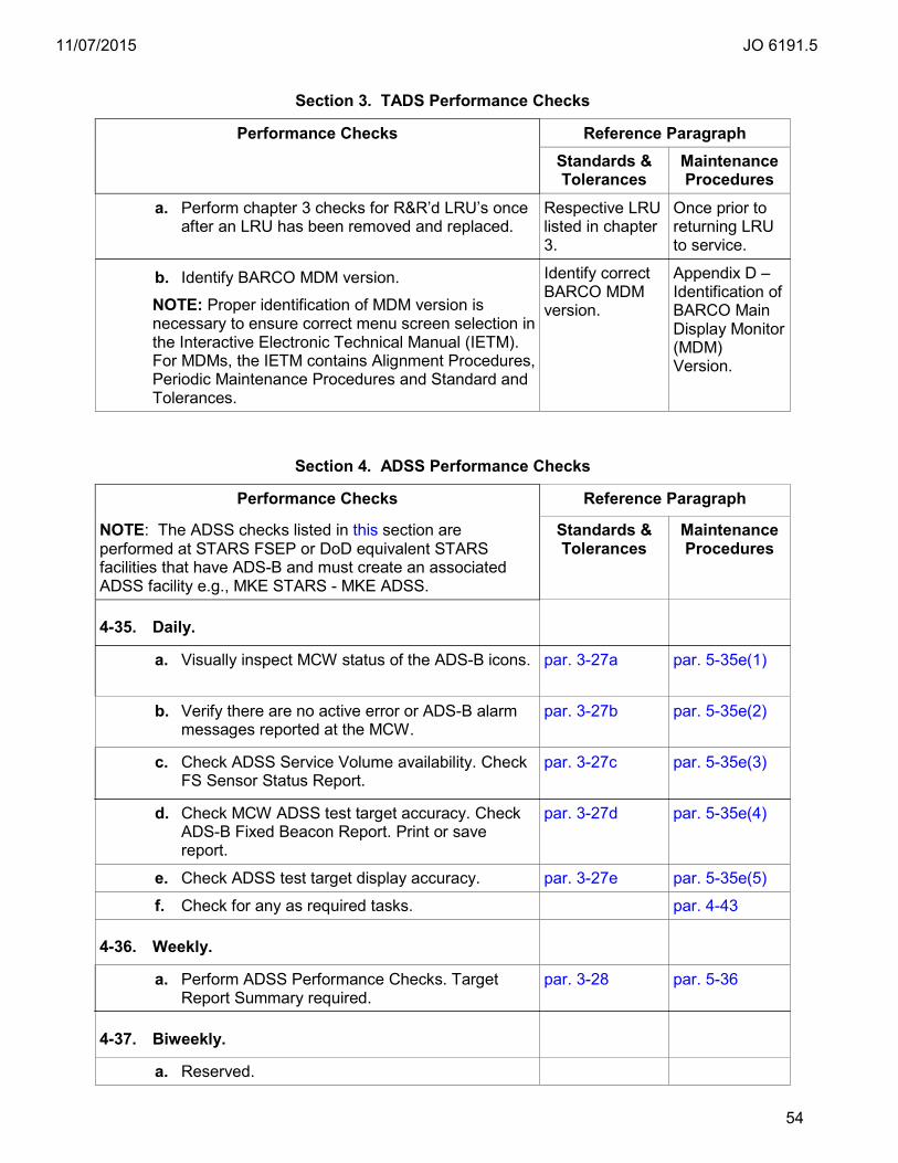
11/07/2015 JO 6191.5
54
Section 3. TADS Performance Checks
Performance Checks Reference Paragraph Standards &
Tolerances Maintenance Procedures
a. Perform chapter 3 checks for R&R’d LRU’s once after an LRU has been removed and replaced.
Respective LRU listed in chapter 3.
Once prior to returning LRU to service.
b. Identify BARCO MDM version.
NOTE: Proper identification of MDM version is necessary to ensure correct menu screen selection in the Interactive Electronic Technical Manual (IETM). For MDMs, the IETM contains Alignment Procedures, Periodic Maintenance Procedures and Standard and Tolerances.
Identify correct BARCO MDM version.
Appendix D – Identification of BARCO Main Display Monitor (MDM) Version.
Section 4. ADSS Performance Checks
Performance Checks Reference Paragraph
NOTE: The ADSS checks listed in this section are performed at STARS FSEP or DoD equivalent STARS facilities that have ADS-B and must create an associated ADSS facility e.g., MKE STARS - MKE ADSS.
Standards & Tolerances
Maintenance Procedures
4-35. Daily.
a. Visually inspect MCW status of the ADS-B icons. par. 3-27a par. 5-35e(1)
b. Verify there are no active error or ADS-B alarm messages reported at the MCW.
par. 3-27b par. 5-35e(2)
c. Check ADSS Service Volume availability. Check FS Sensor Status Report.
par. 3-27c par. 5-35e(3)
d. Check MCW ADSS test target accuracy. Check ADS-B Fixed Beacon Report. Print or save report.
par. 3-27d par. 5-35e(4)
e. Check ADSS test target display accuracy. par. 3-27e par. 5-35e(5)
f. Check for any as required tasks. par. 4-43
4-36. Weekly.
a. Perform ADSS Performance Checks. Target Report Summary required.
par. 3-28 par. 5-36
4-37. Biweekly.
a. Reserved.

11/07/2015 JO 6191.5
55
Section 4. ADSS Performance Checks
Performance Checks Reference Paragraph
NOTE: The ADSS checks listed in this section are performed at STARS FSEP or DoD equivalent STARS facilities that have ADS-B and must create an associated ADSS facility e.g., MKE STARS - MKE ADSS.
Standards & Tolerances
Maintenance Procedures
4-38. Monthly.
a. Reserved.
4-39. Quarterly.
a. Reserved.
4-40. Semiannually.
a. Reserved.
4-41. Annually.
a. Reserved.
4-42. Biannually.
a. Reserved.
4-43. Triannually.
a. Reserved.
4-44. As Required.
a. Reserved.
Section 5. RTDS Performance Checks
Performance Checks Reference Paragraph Standards &
Tolerances Maintenance Procedures
4-45. Daily.
a. Reserved.
4-46. Weekly.
a. FS/EFS System status alert color check. par.3-16 Verified by
par. 5-27

11/07/2015 JO 6191.5
56
Section 5. RTDS Performance Checks
Performance Checks Reference Paragraph Standards &
Tolerances Maintenance Procedures
qualified observer.
b. Check FSL/EFSL Availablity. par. 3-14 Verified by qualified observer.
par, 5-25
c. Verify individual speakers on each of the TDWs. par. 3-67 Verified by qualified observer.
TI 6191.409 Audible Alarm Test or adjust Volume at DCB.
d. RTDS Target display. par. 3-71 No error reported by qualified observer.
Target reports updates and display as expected.
e. RTDS data entry processing and display check. par. 3-72 No error reported by qualified observer.
Tower positions processes data entry and display as expected.
f. Tower Radar to Display Alignment Check. FSL par. 3-24 EFSL par. 3-24
par. 5-31 Par. 5-31
g. Tower Check ADSS test target display accuracy.
FSL par. 3-25 EFSL par. 3-25
par. 5-39 par. 5-39
h. Check TDW visually. Visual satisfaction.
Select TDW alignment map.
4-47. Monthly.
a. Reserved.
b. Reserved.
4-48. Quarterly.
a. Tower Display Monitor (TDM) High Efficiency Particulate Air (HEPA) Filter Inspection and Cleaning (if applicable).
N/A par. 5-54 TI 6191.500
b. Clean TDW unit dust. Dirt and dust free.
Clean unit.
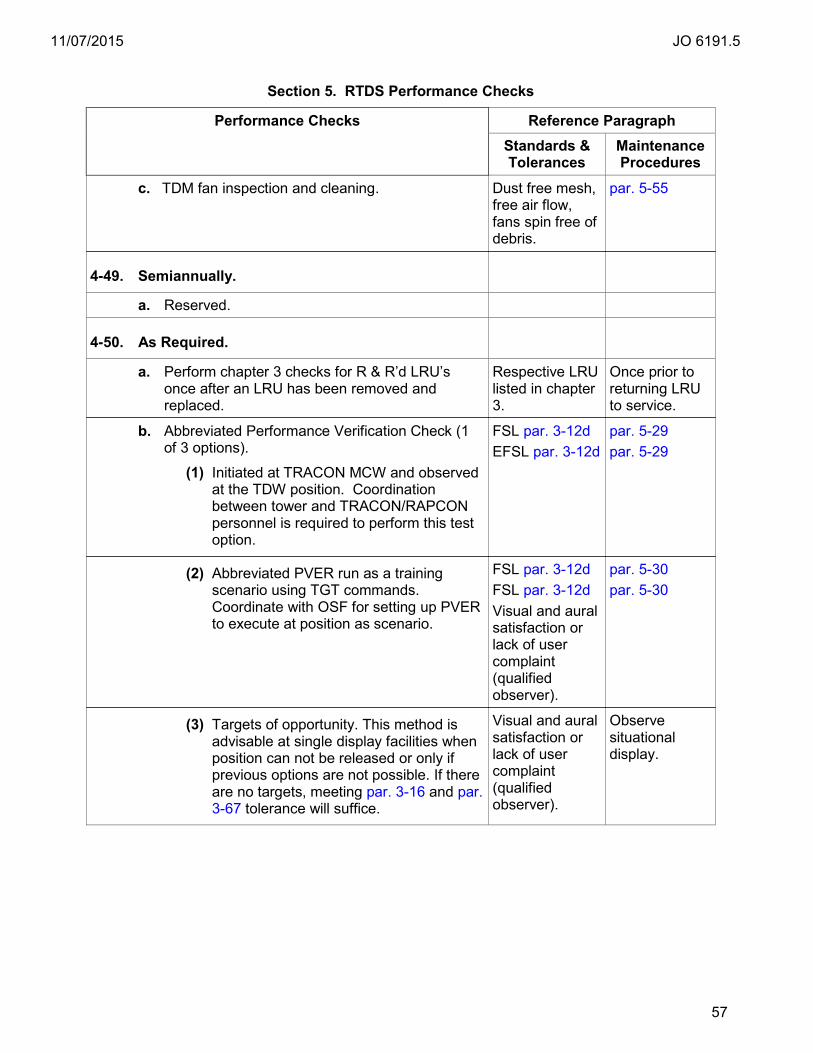
11/07/2015 JO 6191.5
57
Section 5. RTDS Performance Checks
Performance Checks Reference Paragraph Standards &
Tolerances Maintenance Procedures
c. TDM fan inspection and cleaning. Dust free mesh, free air flow, fans spin free of debris.
par. 5-55
4-49. Semiannually.
a. Reserved.
4-50. As Required.
a. Perform chapter 3 checks for R & R’d LRU’s once after an LRU has been removed and replaced.
Respective LRU listed in chapter 3.
Once prior to returning LRU to service.
b. Abbreviated Performance Verification Check (1 of 3 options).
(1) Initiated at TRACON MCW and observed at the TDW position. Coordination between tower and TRACON/RAPCON personnel is required to perform this test option.
FSL par. 3-12d EFSL par. 3-12d
par. 5-29 par. 5-29
(2) Abbreviated PVER run as a training scenario using TGT commands. Coordinate with OSF for setting up PVER to execute at position as scenario.
FSL par. 3-12d FSL par. 3-12d Visual and aural satisfaction or lack of user complaint (qualified observer).
par. 5-30 par. 5-30
(3) Targets of opportunity. This method is advisable at single display facilities when position can not be released or only if previous options are not possible. If there are no targets, meeting par. 3-16 and par. 3-67 tolerance will suffice.
Visual and aural satisfaction or lack of user complaint (qualified observer).
Observe situational display.
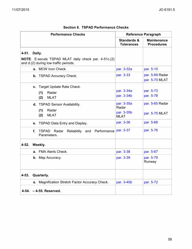
11/07/2015 JO 6191.5
58
Section 6. TSPAD Performance Checks
Performance Checks Reference Paragraph Standards &
Tolerances Maintenance Procedures
4-51. Daily. NOTE: E xecute TSPAD MLAT daily check par. 4-51c.(2) and d.(2) during low traffic periods.
a. MCW Icon Check. par. 3-32a par. 5-10
b. TSPAD Accuracy Check. par. 3-33 par. 5-69 Radar par. 5-70 MLAT
c. Target Update Rate Check.
(1) Radar (2) MLAT
par. 3-34a par. 3-34b
par. 5-73 par. 5-78
d. TSPAD Sensor Availability.
(1) Radar (2) MLAT
par. 3-35a Radar par. 3-35b MLAT
par. 5-65 Radar par. 5-75 MLAT
e. TSPAD Data Entry and Display. par. 3-36 par. 5-68
f. TSPAD Radar Reliability and Performance Parameters.
par. 3-37 par. 5-76
4-52. Weekly.
a. FMA Alerts Check. par. 3-38 par. 5-67
b. Map Accuracy. par. 3-39 par. 5-79 Runway
4-53. Quarterly.
a. Magnification Stretch Factor Accuracy Check. par. 3-40b par. 5-72
4-54. – 4-55. Reserved.

11/07/2015 JO 6191.5
59
Section 7. Other Maintenance Tasks
Performance Checks Reference Paragraph Standards &
Tolerances Maintenance Procedures
4-56. Daily.
a. Clean the Digital Linear Tape (DLT)/ Digital Audio Tape (DAT) drives if the “Use Cleaning Tape” Light Emitting Diode (LED) is illuminated.
LED Extinguished.
TI 6191.500
b. G4 Gang Switch Check. par. 3-46 par. 5-21
4-57. Weekly.
a. Reserved.
4-58. Biweekly.
a. Reserved.
4-59. Monthly.
a. Reserved.
4-60. Bimonthly.
a. Reserved.
4-61. Quarterly.
a. TDM Articulating Arm Check. No observable cracks, excessive wear of signs of fatigue. No signs of leaks. Brake cable and cables free of fraying and obvious damage.
par 5-53
b. Clean all TCW trackballs and keyboards. Manufacturer specifications.
TI 6191.500
c. Check surface of TCW montitor and clean as required.
Visible dirt and smudge free surface.
TI 6191.500 BARCO MDP “Cleaning Glass Display”.
d. Clean TCW and display unit dust. Dirt and dust free.
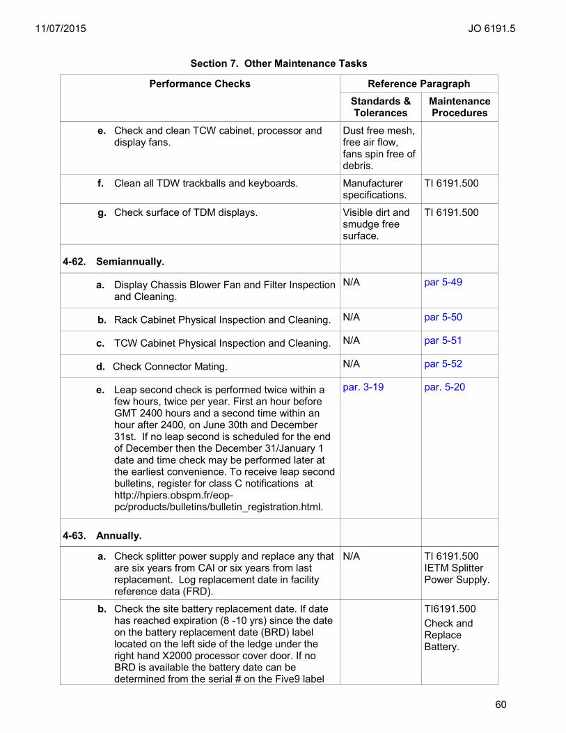
11/07/2015 JO 6191.5
60
Section 7. Other Maintenance Tasks
Performance Checks Reference Paragraph Standards &
Tolerances Maintenance Procedures
e. Check and clean TCW cabinet, processor and display fans.
Dust free mesh, free air flow, fans spin free of debris.
f. Clean all TDW trackballs and keyboards. Manufacturer specifications.
TI 6191.500
g. Check surface of TDM displays. Visible dirt and smudge free surface.
TI 6191.500
4-62. Semiannually.
a. Display Chassis Blower Fan and Filter Inspection and Cleaning.
N/A par 5-49
b. Rack Cabinet Physical Inspection and Cleaning. N/A par 5-50
c. TCW Cabinet Physical Inspection and Cleaning. N/A par 5-51
d. Check Connector Mating. N/A par 5-52
e. Leap second check is performed twice within a few hours, twice per year. First an hour before GMT 2400 hours and a second time within an hour after 2400, on June 30th and December 31st. If no leap second is scheduled for the end of December then the December 31/January 1 date and time check may be performed later at the earliest convenience. To receive leap second bulletins, register for class C notifications at http://hpiers.obspm.fr/eop-pc/products/bulletins/bulletin_registration.html.
par. 3-19 par. 5-20
4-63. Annually.
a. Check splitter power supply and replace any that are six years from CAI or six years from last replacement. Log replacement date in facility reference data (FRD).
N/A TI 6191.500 IETM Splitter Power Supply.
b. Check the site battery replacement date. If date has reached expiration (8 -10 yrs) since the date on the battery replacement date (BRD) label located on the left side of the ledge under the right hand X2000 processor cover door. If no BRD is available the battery date can be determined from the serial # on the Five9 label
TI6191.500 Check and Replace Battery.
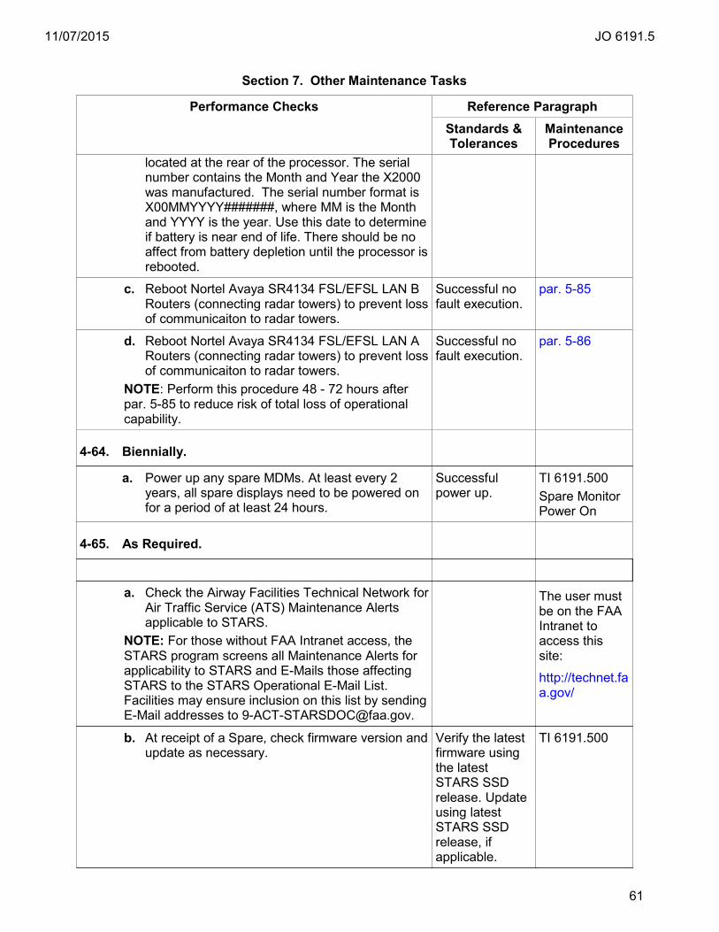
11/07/2015 JO 6191.5
61
Section 7. Other Maintenance Tasks
Performance Checks Reference Paragraph Standards &
Tolerances Maintenance Procedures
located at the rear of the processor. The serial number contains the Month and Year the X2000 was manufactured. The serial number format is X00MMYYYY#######, where MM is the Month and YYYY is the year. Use this date to determine if battery is near end of life. There should be no affect from battery depletion until the processor is rebooted.
c. Reboot Nortel Avaya SR4134 FSL/EFSL LAN B Routers (connecting radar towers) to prevent loss of communicaiton to radar towers.
Successful no fault execution.
par. 5-85
d. Reboot Nortel Avaya SR4134 FSL/EFSL LAN A Routers (connecting radar towers) to prevent loss of communicaiton to radar towers.
NOTE: Perform this procedure 48 - 72 hours after par. 5-85 to reduce risk of total loss of operational capability.
Successful no fault execution.
par. 5-86
4-64. Biennially.
a. Power up any spare MDMs. At least every 2 years, all spare displays need to be powered on for a period of at least 24 hours.
Successful power up.
TI 6191.500 Spare Monitor Power On
4-65. As Required.
a. Check the Airway Facilities Technical Network for Air Traffic Service (ATS) Maintenance Alerts applicable to STARS.
NOTE: For those without FAA Intranet access, the STARS program screens all Maintenance Alerts for applicability to STARS and E-Mails those affecting STARS to the STARS Operational E-Mail List. Facilities may ensure inclusion on this list by sending E-Mail addresses to [email protected].
The user must be on the FAA Intranet to access this site:
http://technet.faa.gov/
b. At receipt of a Spare, check firmware version and update as necessary.
Verify the latest firmware using the latest STARS SSD release. Update using latest STARS SSD release, if applicable.
TI 6191.500
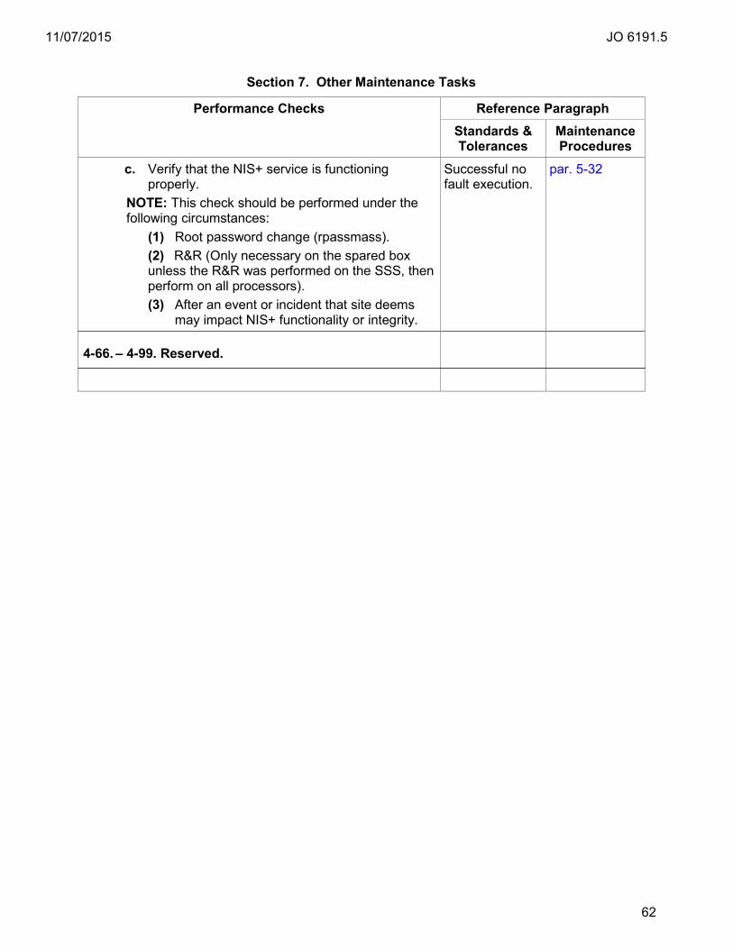
11/07/2015 JO 6191.5
62
Section 7. Other Maintenance Tasks
Performance Checks Reference Paragraph Standards &
Tolerances Maintenance Procedures
c. Verify that the NIS+ service is functioning properly.
NOTE: This check should be performed under the following circumstances:
(1) Root password change (rpassmass). (2) R&R (Only necessary on the spared box unless the R&R was performed on the SSS, then perform on all processors). (3) After an event or incident that site deems
may impact NIS+ functionality or integrity.
Successful no fault execution.
par. 5-32
4-66. – 4-99. Reserved.
11/07/2015 JO 6191.5
63
Chapter 5. Maintenance Procedures
5-1. General. This chapter establishes the procedures for accomplishing the various essential maintenance activities that are required for G4 configurations on ei ther a per iodic or incidental basis. The chapter is divided into three sections. The first section describes the procedures to be us ed in making the performance checks listed in chapter 4, section 1. The second section describes the procedures for doing the tasks listed in chapter 4, section 2. The third section describes the procedures for doing special tasks, usually nonscheduled and not listed in chapter 4.
5-2. Technical Performance Record Entries. Order 6000.15, General Maintenance Handbook for NAS Facilities contains guidance and detailed instructions for field utilization and tracking of Technical Performance Record (TPR) data. The Engineering organization has determined that there is no requirement to document or track performance parameters on a TPR for this STARS system.
5-3. – 5-9. Reserved.

11/07/2015 JO 6191.5
64
SECTION 1. PERFORMANCE CHECK PROCEDURES
5-10. MCW System Icon Check. a. Objective. Verify that the minimum required resources that can sustain ATC operations
are present and working properly. If ADS-B is utilized, verify that the minimum required resources to support ADS-B with fusion display are present and working properly. If FMA is utilized, verify that the minimum required resources to support FMA are present and working properly.
b. Discussion. STARS icons are color coded to indicate status of monitored equipment, interfaces or software conditions. Many of the STARS MCW icons are hierarchal. If the top level icon is GREEN/PASS then the detailed status below is GREEN/PASS also. A top level YELLOW/WARNING icon is caused by a lower level detail red, yellow or gray condition. Iconic state changes are typically accompanied with system messages that report additional information. If icons indicate RED/FAIL or YELLOW/WARNING then for trouble-shooting purposes check the system messages for additional information. There are eight types of system messages; ALARM, ALERT, NORMAL, State, Info, Command, Error, and SEC. ALARM, ALERT and Error types are error messages and are most notable for system verification. SEC are security messages. System error messages come in four states: START, FAIL, COUNT, and CLEAR. START messages are displayed the first time an error or report occurs and contain value filled parameter information about the error event. C OUNT messages fill the parameter fields with asteriks and are meant to indicate that the error condition continues and reported at the rate of xx / 600 where xx is a number of instances and 600 is in seconds. CLEAR messages indicate the error condition has recovered. FAIL messages indicate that a monitored component in STARS has exceeded a t hreshold (x number of allowable reports per y period) and therefore is considered in a fault state. Each system message has a num ber. System error START message are particularly useful for trouble-shooting and monitoring and can be looked up in TI 6191.404 STARS System Message Dictionary (SSMD). The SSMD provides much more detailed information concerning system messages in general, as well as, specific information about each message type. Failure messages are also accompanied by an aural alarm from the MCW only.
c. Test Equipment Required. Not applicable. d. Conditions. These checks must be made while operational programs are being
executed. This includes ADS-B and FMA, if these are utilized. FMA can be used with radar input or MLAT. In the event of ADS-B, FMA/MLAT or FMA/radar usage, respective icons and messages should be checked for these capabilities.
e. Detailed Procedure. Check iconic indications on the FSL and/or EFSL MCW: (1) Check that the minimum required resources (MCW, NUNIO, CGW, RDP, and LAN
equipment) are available.
(2) Check MCW, for all available TCW displays, for status and for any active FAIL icons.
(3) Check MCW, for all available TDW displays, for status and for any active FAIL icons.
(4) If ADS-B is utilized check that that the minimum resources to support ADS-B are available.
(a) Check ADS-B sensor icon.
(b) Check AIG ROUTERS icon for state information.
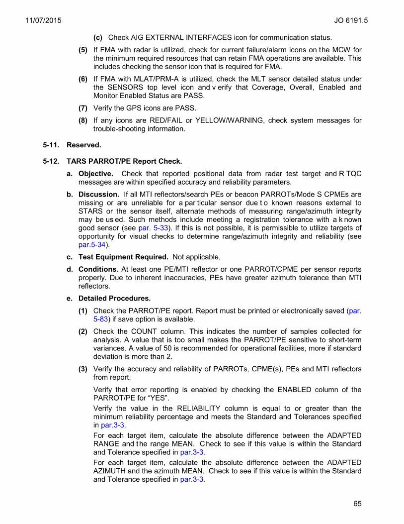
11/07/2015 JO 6191.5
65
(c) Check AIG EXTERNAL INTERFACES icon for communication status.
(5) If FMA with radar is utilized, check for current failure/alarm icons on the MCW for the minimum required resources that can retain FMA operations are available. This includes checking the sensor icon that is required for FMA.
(6) If FMA with MLAT/PRM-A is utilized, check the MLT sensor detailed status under the SENSORS top level icon and v erify that Coverage, Overall, Enabled and Monitor Enabled Status are PASS.
(7) Verify the GPS icons are PASS.
(8) If any icons are RED/FAIL or YELLOW/WARNING, check system messages for trouble-shooting information.
5-11. Reserved.
5-12. TARS PARROT/PE Report Check. a. Objective. Check that reported positional data from radar test target and R TQC
messages are within specified accuracy and reliability parameters. b. Discussion. If all MTI reflectors/search PEs or beacon PARROTs/Mode S CPMEs are
missing or are unreliable for a par ticular sensor due t o known reasons external to STARS or the sensor itself, alternate methods of measuring range/azimuth integrity may be us ed. Such methods include meeting a registration tolerance with a k nown good sensor (see par. 5-33). If this is not possible, it is permissible to utilize targets of opportunity for visual checks to determine range/azimuth integrity and reliability (see par.5-34).
c. Test Equipment Required. Not applicable. d. Conditions. At least one PE/MTI reflector or one PARROT/CPME per sensor reports
properly. Due to inherent inaccuracies, PEs have greater azimuth tolerance than MTI reflectors.
e. Detailed Procedures. (1) Check the PARROT/PE report. Report must be printed or electronically saved (par.
5-83) if save option is available.
(2) Check the COUNT column. This indicates the number of samples collected for analysis. A value that is too small makes the PARROT/PE sensitive to short-term variances. A value of 50 is recommended for operational facilities, more if standard deviation is more than 2.
(3) Verify the accuracy and reliability of PARROTs, CPME(s), PEs and MTI reflectors from report. Verify that error reporting is enabled by checking the ENABLED column of the PARROT/PE for “YES”. Verify the value in the RELIABILITY column is equal to or greater than the minimum reliability percentage and meets the Standard and Tolerances specified in par.3-3. For each target item, calculate the absolute difference between the ADAPTED RANGE and the range MEAN. Check to see if this value is within the Standard and Tolerance specified in par.3-3. For each target item, calculate the absolute difference between the ADAPTED AZIMUTH and the azimuth MEAN. Check to see if this value is within the Standard and Tolerance specified in par.3-3.

11/07/2015 JO 6191.5
66
(4) If one P ARROT or PE is within accuracy tolerance (no failed indications) and another is failed, most likely the radar should not be failed. It is permissible to disable the monitoring of the failed PARROT/CPME from the MCW to disable failure indications on the displays. Truly misaligned radars should exhibit alignment or registration issues, in addition to, possible out of tolerance PARROT/PE(s). It is recommended to consult with air traffic and pe rform Par. 5-33 and 5-34 before taking or sustaining a r adar offline. If necessary, disable the monitoring of any failed PARROT/PE if the radar passes the latter checks and contact Hardware Field Support.
5-13. Radar to Display Alignment. a. Objective. Check the position of available radar test targets on fixed target maps to
verify correct alignment on displays. b. Discussion. This check verifies that radar reports are displayed at correct positions in
support of ATC operations. This check is required at one di splay, at minimum. Since STARS software and adaptation are checksummed digital copies, performing this check on one display verifies it for the system. The certifying official may corroborate with ATC to verify that radar reports are displayed at expected locations, particularly arrivals on runway centerlines. This check should be m ade on di fferent positions than last executed if possible.
NOTE: The discussion and condition per par. 5-12 are applicable for this check. In addition alternative methods (see par. 5-34) including runway centerline checks are permissible in the event that there are corrections required or missing items on the fixed target map (FTM).
c. Test Equipment Required. A fixed target map(s) with radar test target geo-boxes, carets or symbols appropriate for all applicable sensors. Familiarity with test target positions and which radars they are associated with is useful. A copy of a PARROT/PE report may be useful.
d. Conditions. These checks must be made while the operational program is being executed. RADAR targets may not display an extent symbol due to an adaptable firmness parameter. MTI/PE and SRTQC do not meet firmness adaptation, they will display as search plots i.e., blue squares.
e. Detailed Procedures. (1) Verify proper data entry and di splay functions of PE/MTI, PARROT/CPME, and
RTQC test targets at selected TCW(s). NOTE: At STARS facilities (TRACON, RAPCON etc.), all radar test targets are checked. At RTDS facilities (towers), at minimum, only one radar test target is checked.
(a) Select fusion display mode. If fusion mode is not available this check is performed in multi-mode for all targets; or in single-sensor checking each sensor. (Reference step (2) & (3).)
(b) Select the geographic map(s) that contain fixed target geo-boxes, geo-dots or marks for fixed test targets for all sensors in the site sensor configuration that are currently available. Verify that the correct map(s) is displayed. See Appendix E for radar fixed target map details.
(c) Enable RTQC display from the DCB.
(d) Select the BRITE button on the DCB and select and set the following:
1. MPA to 100
2. MPB to 100

11/07/2015 JO 6191.5
67
3. POS to 100
4. BCN to 0 (Turns BCN off)
5. PRI to 0 (Turns PRI off) or set to 50 or greater to view plots (see step h, j or k).
6. Select DONE
(e) Select the CHAR button on the DCB and select and set the following:
1. POS to 1
2. Select DONE
(f) Enter <MULTI FUNC> <space> <B> <ENTER> to display beacon codes.
(g) It is recommended that settings are saved in a pr eference set for each test target position. Reference TI 6191.409 for preference set instructions.
(h) If necessary, zoom out and toggle the RTQC button to assist in finding any test target. Adjust display as necessary for optimum viewing. If SRTQC and MTI/PEs do not meet adapted firmness then it may be necessary to adjust PRI to some visible value and toggle the RTQC button to view them as plots.
(i) Verify that radar PARROT/CPMEs position symbols are displayed on or within the appropriate geo-boxes or adapted map location symbols or are displayed at expected positions. Verify correct Mode 3/A and Mode C.
(j) Verify that radar beacon and search RTQCs position or plot symbols are displayed on or within the appropriate geo-boxes or adapted map location symbols or are displayed at expected positions. Verify correct Mode 3/A and Mode C for beacon RTQCs.
(k) Verify that radar PE/MTI position or plot symbols are displayed on or within the appropriate geo-boxes or adapted map location symbols or are displayed at expected positions.
(2) Optionally this procedure can be per formed in single-sensor display for each available sensor. In this case the test target will display as a position symbol if tracked and PRI is 0. It may display as an extent or plot if PRI is non-zero and if the target meets or does not meet the adapted firmness criteria, respectively.
(3) If multi-mode is accessible and/or part of the operational mission; these checks can be performed in multi-mode by switching the display to multi-radar mode by selecting the SITE button on the DCB and selecting MULT.
(4) After checking all desired and available sensors and display modes, return display to normal operations.
5-14. Radar RTQC Report Check. a. Objective. Verify that radar data input into STARS meets radar performance
parameters listed in par. 3-5. b. Discussion. The performance parameters should be reasonable for a properly aligned
radar and digitizer system. However, situations unique to each site (e.g., obstructions, large bodies of water, antenna tilt, anomalous propagation) may prevent some radar sites from meeting the established criteria. For this reason each site should establish a baseline for each sensor utilized by the SOS. The baseline values should be utilized to determine if sensor is performing normally. See par. 5-41 for the radar performance baseline procedure.
11/07/2015 JO 6191.5
68
(1) When a pa rameter does not meet the criteria established in Section 3, the FSL subsystem may still be c ertified provided the sensor is performing to recorded mean values. However, the reason for not meeting performance parameters should be identified and documented. Every effort should be made to bring the radar and digitizer up to specifications.
(2) Some of the threshold parameters (i.e., SEARCH RTQC, BEACON RTQC RELIABILITYs) are adaptable. It is possible, for example, that results greater than 100 percent are obtainable. The site should confer with the OSFs and second level support to verify what the normal limits are for each adaptable parameter for each sensor and ensure that these are set accordingly. Every effort should be made to make the radar or digitizer meet specifications. In the event that this is not possible for site specific reasons, the site should determine and document the specific reasons.
c. Test Equipment Required. Not applicable. d. Conditions. This procedure should be performed on operational sensors only. e. Detailed Procedures.
(1) Check RTQC Check Report by selecting Reports/RTQC Check Report. Report must be printed or electronically saved (par. 5-83) if save option is available.
(2) Enter the maximum value possible; 15 minutes. (3) Verify performance parameters listed in standards and tolerances par. 3-5.
5-15. TARS Registration Performance (CALC MODE). a. Objective. Ensure that registration bias for adapted radar pairs is within the operating
tolerance and is as close as possible to the standard tolerances specified.
NOTE: This procedure is for radars in CALC registration operating mode. Registration mode is checked at the MCW by selecting <System Parameters><Radar>< Registration operating mode> for each radar. NOTE: In situations when registration certification is needed at a t ime that it is not recommended to execute, e.g., during a ni ght time site adaption change, perform the procedure described in par. 5-17 until the designated method can be r un at peak traffic times.
b. Discussion. During initial setup (pre-IOC), it may be necessary to apply corrections that exceed threshold values cited later in this paragraph as part of a baseline process. See par. 5-40 for the registration baseline procedure. It is best to report initial setup registration issues to the Hardware Field Support team, assigned OSF, and/or Technical Operations Field Service Area Offices. If there is uncertainty to whom to report, contact the PMO Helpdesk 1(800)377-0308 and ask for Hardware Field Support.
Registration bias that exceeds the operational tolerances may contribute to track anomalies such as track splits, track suppression, velocity fluctuations and duplicate beacons. In addition, the STARS tracker performs optimally when registration bias is as close as possible to standard values. Therefore, it is critical to maintain registration bias as close to standard as possible.
Prior to registration analysis, it is necessary to have all sensors that contribute to the STARS multi-tracker adapted correctly to site survey information, or to the best available local and/or regional information. Precision is key. The critical components are positional (i.e., latitude/longitude, range/azimuth, altitude, etc.) of sensors, PARROTS/CPMES, and RTQCs. North correction angles (magnetic declination) and radar tile sets are also critical. The values in STARS adaptation should be consistent

11/07/2015 JO 6191.5
69
with adaptation used by regional and co-regional (if applicable) facilities constituent to the STARS multi-radar complex.
In CALC mode, corrections must be appl ied by selecting the APPLY button on the registration report. When a registration correction is applied, it adds (or subtracts) two values, one range and one azimuth, to the positional data reported from a sensor. The corrected positions are not used for MCW test target monitoring, but they will change target positions on the display. In addition, coordinate with AT to check that approaches are aligning on runway centerlines at primary and/or secondary airports. Also check for duplicate targets. If the displayed target positions are not positioned satisfactorily, different values may need to be entered. Contact the Helpdesk for clarification of this point.
NOTE: The registration report should be analyzed and applied during high traffic periods. It is also important to allow the system to stabilize values after a restart. Errors may be observed until stabilization has occurred. This could be delayed if this is done during low traffic periods which is typical for planned restarts. Having good default startup values could mitigate this. In CALC mode, errors without good default values may be observed until corrections are applied. Please consult with your OSF for additional information or contact Hardware Field Support.
c. Test Equipment Required. Surveyed data, FRD, radar data worksheets, regional adaptation, and/or STARS radar adaptation.
d. Conditions. Registration is possible on sensor pairings only. Sensor pairings used for sensor registration are defined in adaptation using the DMS. Only adapted sensor pairings qualify for analysis using the registration report at the MCW position. To effectively implement the functions provided by the Registration Collimation Report, sensors must be within the certification window per the procedures specified in Appendix A of this handbook. Perform this task during site busy period.
e. Detailed Procedure. (1) If necessary, contact the OSF to check if default startup values are adapted.
(2) Check for registration system icons and messages.
(3) Open and check Registration Report. Report must be printed or electronically saved (par. 5-83) if save option is available.
(4) If the report has DIFF columns for range and azimuth (shown in Figure 5-1 below under range and azimuth columns; to right of RECOMM), compare the DIFF values for each radar row to the appropriate table entry by skipping to step (8). Otherwise go to next step.
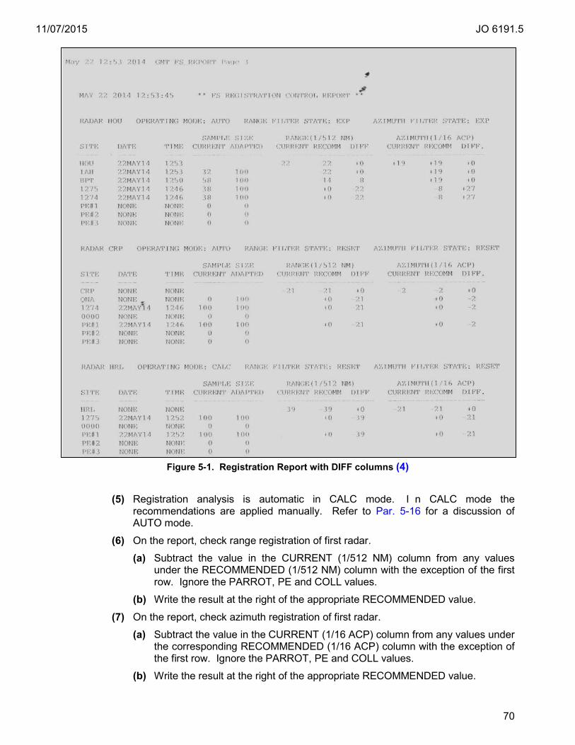
11/07/2015 JO 6191.5
70
Figure 5-1. Registration Report with DIFF columns (4)
(5) Registration analysis is automatic in CALC mode. I n CALC mode the recommendations are applied manually. Refer to Par. 5-16 for a discussion of AUTO mode.
(6) On the report, check range registration of first radar.
(a) Subtract the value in the CURRENT (1/512 NM) column from any values under the RECOMMENDED (1/512 NM) column with the exception of the first row. Ignore the PARROT, PE and COLL values.
(b) Write the result at the right of the appropriate RECOMMENDED value.
(7) On the report, check azimuth registration of first radar.
(a) Subtract the value in the CURRENT (1/16 ACP) column from any values under the corresponding RECOMMENDED (1/16 ACP) column with the exception of the first row. Ignore the PARROT, PE and COLL values.
(b) Write the result at the right of the appropriate RECOMMENDED value.
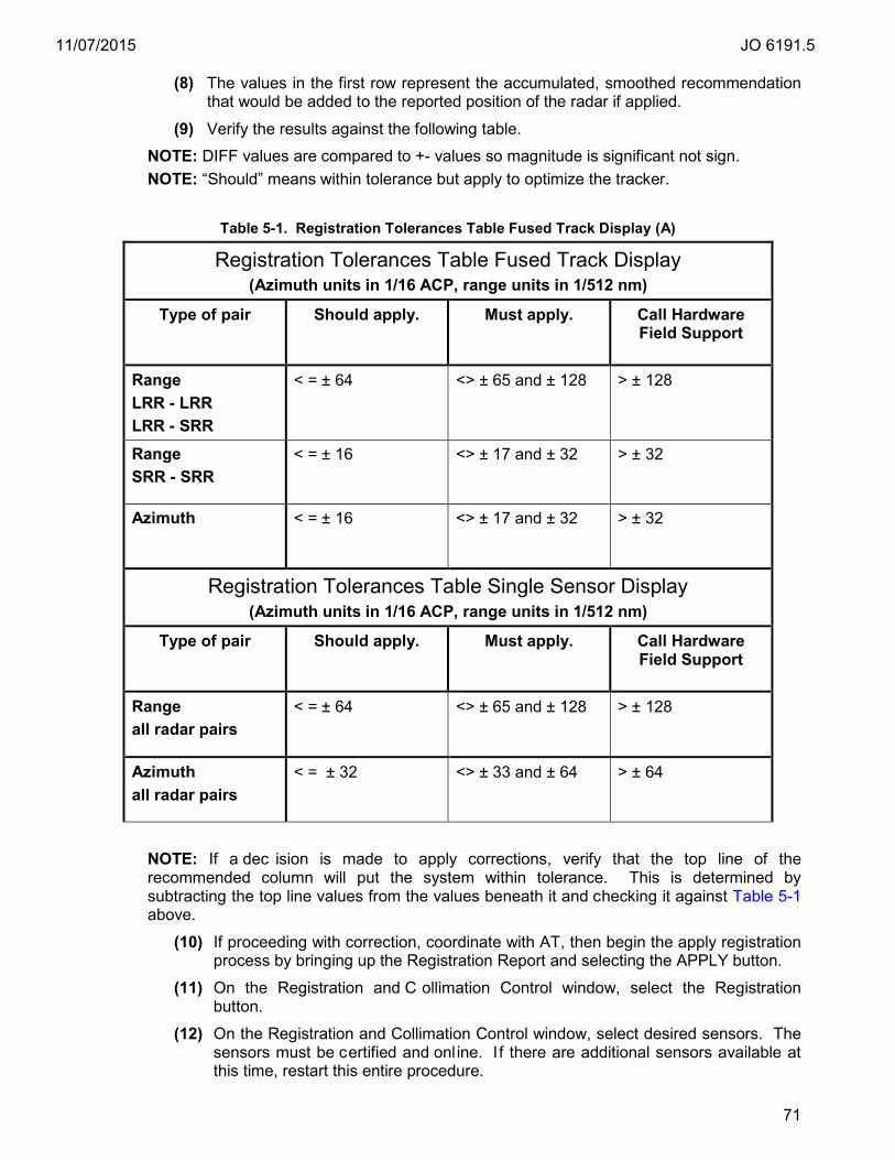
11/07/2015 JO 6191.5
71
(8) The values in the first row represent the accumulated, smoothed recommendation that would be added to the reported position of the radar if applied.
(9) Verify the results against the following table.
NOTE: DIFF values are compared to +- values so magnitude is significant not sign. NOTE: “Should” means within tolerance but apply to optimize the tracker.
Table 5-1. Registration Tolerances Table Fused Track Display (A)
Registration Tolerances Table Fused Track Display (Azimuth units in 1/16 ACP, range units in 1/512 nm)
Type of pair Should apply. Must apply. Call Hardware Field Support
Range LRR - LRR LRR - SRR
< = ± 64 <> ± 65 and ± 128 > ± 128
Range SRR - SRR
< = ± 16 <> ± 17 and ± 32 > ± 32
Azimuth < = ± 16 <> ± 17 and ± 32 > ± 32
Registration Tolerances Table Single Sensor Display (Azimuth units in 1/16 ACP, range units in 1/512 nm)
Type of pair
Should apply. Must apply. Call Hardware Field Support
Range all radar pairs
< = ± 64 <> ± 65 and ± 128 > ± 128
Azimuth all radar pairs
< = ± 32 <> ± 33 and ± 64 > ± 64
NOTE: If a dec ision is made to apply corrections, verify that the top line of the recommended column will put the system within tolerance. This is determined by subtracting the top line values from the values beneath it and checking it against Table 5-1 above.
(10) If proceeding with correction, coordinate with AT, then begin the apply registration process by bringing up the Registration Report and selecting the APPLY button.
(11) On the Registration and C ollimation Control window, select the Registration button.
(12) On the Registration and Collimation Control window, select desired sensors. The sensors must be certified and onl ine. I f there are additional sensors available at this time, restart this entire procedure.
11/07/2015 JO 6191.5
72
NOTE: The next action will apply the top-line recommended correction from the RECOMMENDED column for both range and az imuth for any sensor selected on the Control window. They are applied to uncorrected data and are not added to previous corrections.
(13) On the Warning Window, at the “PROCEED WITH VSP CHANGE?”, select YES. On the Registration and Collimation Control window, select CANCEL.
(14) Select the REFRESH button to update the report and verify the corrections are applied by examining the CURRENT column.
(15) If the system passes listed checks, repeat steps (1) to (14) of this procedure to verify acceptable registration using the Registration and Collimation report.
NOTE: Registration corrections can be undone by changing registration correction VSPs at the MCW.
5-16. TARS Registration Performance (AUTO MODE). a. Objective. Ensure that registration bias for adapted radar pairs is within the operating
tolerance and is as close as possible to the standard tolerances specified.
NOTE: This procedure is for radars in AUTO registration operating mode. Registration mode is checked at the MCW by selecting <System Parameters><Radar>< Registration operating mode> for each radar. NOTE: In situations when registration certification is needed at a t ime that it is not recommended to execute, e.g., during a ni ght time site adaption change, perform the procedure described in par. 5-17 until the designated method can be r un at peak traffic times.
b. Discussion. During initial setup (pre-IOC), it may be necessary to apply corrections that exceed threshold values cited later in this paragraph as part of a baseline process. See par. 5-40 for the registration baseline procedure. It is best to report initial setup registration issues to the Hardware Field Support team, assigned OSF, and/or Technical Operations Field Service Area Offices. If there is uncertainty to whom to report, contact the PMO Helpdesk 1(800)377-0308 and ask for Hardware Field Support.
Registration bias that exceeds the operational tolerances may contribute to track anomalies such as track splits, track suppression, velocity fluctuations and duplicate beacons. In addition, the STARS tracker performs optimally when registration bias is as close as possible to standard values. Therefore, it is critical to maintain registration bias as close to standard as possible.
Prior to registration analysis, it is necessary to have all sensors that contribute to the STARS multi-tracker adapted correctly to precision survey information. If that is not possible the best available data can be used but it must be logged in the FRD as “no precision survey available”. Precision is key. The critical components are positional (i.e., latitude/longitude, range/azimuth, altitude, etc.) of sensors, PARROTS/CPMES, and RTQCs. North correction angles (magnetic declination) and r adar tile sets are also critical. The values in STARS adaptation should be consistent with adaptation used by regional and c o-regional (if applicable) facilities constituent to the STARS multi-radar complex. The registration report should be run during high traffic periods.
In AUTO mode, corrections are automatically applied once the registration calculation is complete. When a registration correction is applied, it adds (or subtracts) two values, one range and one az imuth, to the positional data reported from a sensor. The corrected positions are not used for MCW test target monitoring, but they will change target positions on the display. In addition, coordinate with AT to check that approaches are aligning on runway centerlines at primary and/or secondary airports. Also check for
11/07/2015 JO 6191.5
73
duplicate targets. If the displayed target positions are not positioned satisfactorily, different values may need to be entered. Contact the Helpdesk for clarification of this point.
Automatic registration utilizes the same algorithms as non-automatic registration but the results are applied automatically without manual intervention whenever the analysis is complete. Automatic registration, when activated either from an MCW VSP (AUTO) or adaptation, will continually analyze and apply registration bias corrections whenever the adapted sample size is reached before the adapted time period completes. Automatic registration has provisions for adapting thresholds and tolerances to prevent applying bias corrections that are deemed to be ex cessive or not reasonable for a pr operly functioning system. If single pass corrections exceed the adapted threshold, STARS will issue system messages azimuth and/or range correction error messages. If the bias correction is applied to the smoothing filter and the tolerance is exceeded, the calculation is not applied, an alarm is indicated at the MCW and the SSA, and system messages #321(range) or #322(azimuth) are displayed. The alarm will clear once the smoothed correction returns to tolerance. R egistration corrections are applied to PARROTs, PEs, and GBTs but not to RTQCs or sector marks. If at any time the sensor is excluded from registration calculations by the MCW VSP, configured off-line, or disabled from tracking at the AT supervisor keyboard, the recommended and appl ied bias corrections revert back to adapted defaults and alarms or alerts clear. Any manual entries cause the system to revert to CALC or manual mode.
NOTE: With automatic registration, the OSFs should provide values for sample size and time to reduce or eliminate low traffic period corrections. The registration report should be analyzed and applied during high traffic periods. It is also important to allow the system to stabilize values after a restart. Errors may be observed until stabilization has occurred. This could be del ayed if this is done du ring low traffic periods, which is typical for planned restarts. Having good default startup values could mitigate this. AUTO mode is not recommended without good default values. Please consult with your OSF for additional information or contact Hardware Field Support.
c. Test Equipment Required. Surveyed data, FRD, radar data worksheets, regional adaptation, and/or STARS sensor adaptation.
d. Conditions. Registration is possible on sensor pairings only. Sensor pairings used for sensor registration are defined in adaptation using the DMS. Only adapted sensor pairings qualify for analysis using the registration report at the MCW position. To effectively implement the functions provided by the Registration Collimation Report, sensors must be within the certification window per the procedures specified in Appendix A of this handbook. Perform this task during site busy period.
e. Detailed Procedure. (1) If necessary, contact the OSF to verify that automatic registration is properly adapted for operational use.
(2) Check for registration system icons and/or messages.
(3) Verify at the registration mode by selecting <System Parameters><Radar>< Registration operating mode>.
(4) Registration analysis is automatic in AUTO and CALC mode. In CALC mode the recommendations are applied manually. Refer to Par. 5-15 for a discussion of CALC mode.
(5) Successful analysis can be determined by noting the DATE and TIME columns and comparing values with the report time and times from other pairs. The times should be within minutes of each other. When registration analysis completes for any pair,
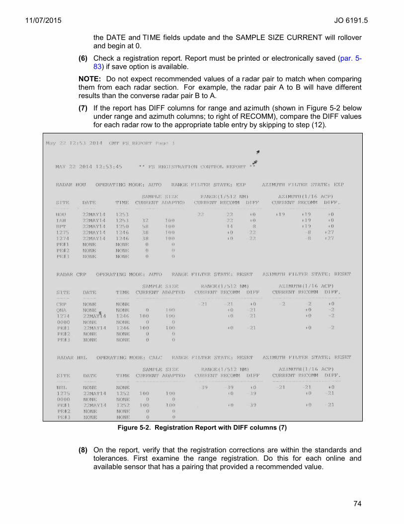
11/07/2015 JO 6191.5
74
the DATE and TIME fields update and the SAMPLE SIZE CURRENT will rollover and begin at 0.
(6) Check a registration report. Report must be printed or electronically saved (par. 5-83) if save option is available.
NOTE: Do not expect recommended values of a radar pair to match when comparing them from each radar section. For example, the radar pair A to B will have different results than the converse radar pair B to A.
(7) If the report has DIFF columns for range and azimuth (shown in Figure 5-2 below under range and azimuth columns; to right of RECOMM), compare the DIFF values for each radar row to the appropriate table entry by skipping to step (12).
Figure 5-2. Registration Report with DIFF columns (7)
(8) On the report, verify that the registration corrections are within the standards and tolerances. First examine the range registration. Do this for each online and available sensor that has a pairing that provided a recommended value.

11/07/2015 JO 6191.5
75
(a) Subtract any values that may be i n the CURRENT (1/512 NM) column from any values under the corresponding RECOMMENDED (1/512 NM) column with the exception of the first row. Ignore the PARROT, PE and COLL values. Remember that subtraction of a ne gative number becomes addition of a positive number.
(b) Write the result at the right of the appropriate RECOMMENDED value.
(9) Perform the azimuth registration analysis. Again, do this for each online and available sensor that has a pairing that provided a recommended value.
(a) Subtract any values that may be i n the CURRENT (1/16 ACP) column from any values under the corresponding RECOMMENDED (1/16 ACP) column with the exception of the first row. Ignore the PARROT, PE and COLL values. Remember that subtraction of negative number becomes addition of a positive number.
(b) Write the result at the right of the appropriate RECOMMENDED value.
(10) The values in the first row represent the accumulated, smoothed recommendation that will be added to the reported position of the radar when applied.
(11) Check the deltas against the standards and tolerances for non-fused or fused track whichever is appropriate.
(12) Verify the results against the following table.
NOTE: DIFF values are compared to +- values so magnitude is significant not sign. NOTE: “Should” means within tolerance but apply to optimize the tracker. In AUTO mode all bias corrections are applied as soon as the analysis is complete.
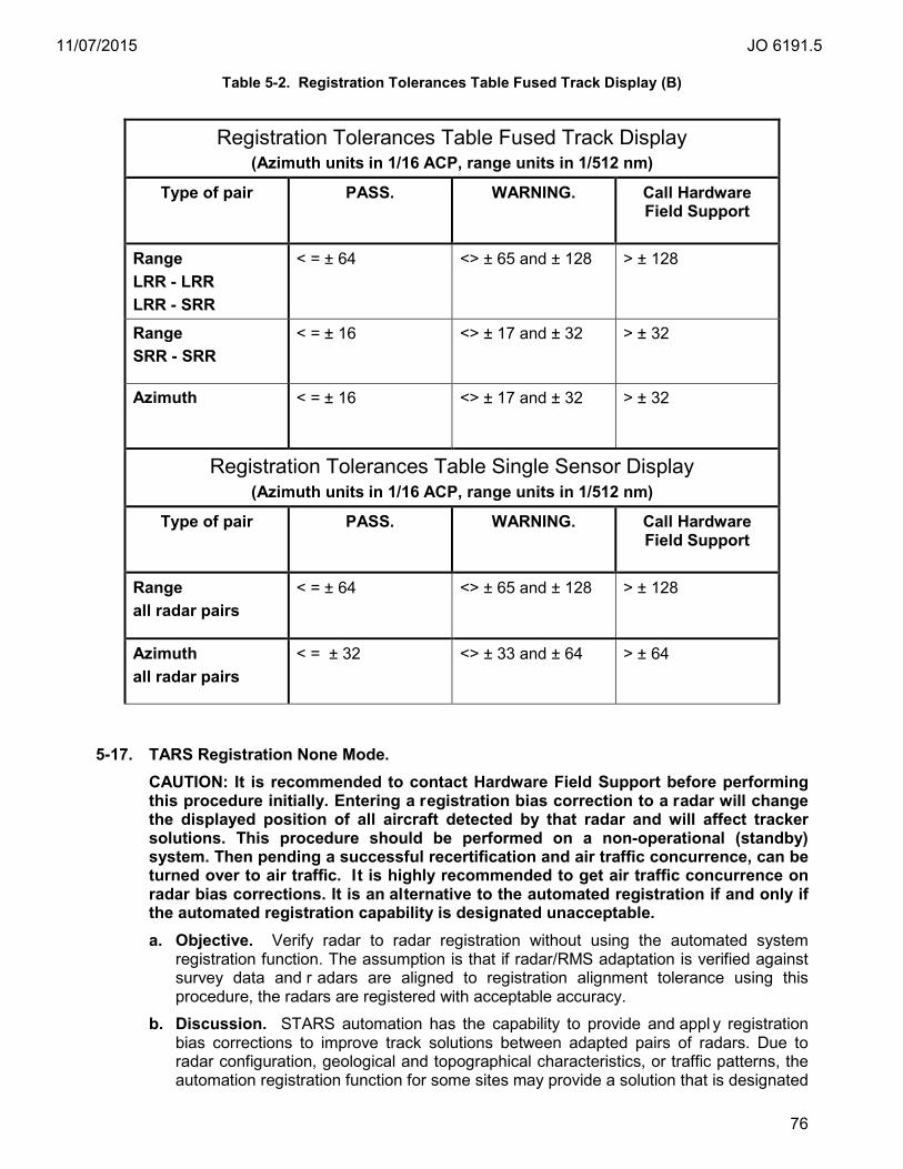
11/07/2015 JO 6191.5
76
Table 5-2. Registration Tolerances Table Fused Track Display (B)
Registration Tolerances Table Fused Track Display (Azimuth units in 1/16 ACP, range units in 1/512 nm)
Type of pair PASS. WARNING. Call Hardware Field Support
Range LRR - LRR LRR - SRR
< = ± 64 <> ± 65 and ± 128 > ± 128
Range SRR - SRR
< = ± 16 <> ± 17 and ± 32 > ± 32
Azimuth < = ± 16 <> ± 17 and ± 32 > ± 32
Registration Tolerances Table Single Sensor Display (Azimuth units in 1/16 ACP, range units in 1/512 nm)
Type of pair
PASS. WARNING. Call Hardware Field Support
Range all radar pairs
< = ± 64 <> ± 65 and ± 128 > ± 128
Azimuth all radar pairs
< = ± 32 <> ± 33 and ± 64 > ± 64
5-17. TARS Registration None Mode. CAUTION: It is recommended to contact Hardware Field Support before performing this procedure initially. Entering a registration bias correction to a radar will change the displayed position of all aircraft detected by that radar and will affect tracker solutions. This procedure should be performed on a non-operational (standby) system. Then pending a successful recertification and air traffic concurrence, can be turned over to air traffic. It is highly recommended to get air traffic concurrence on radar bias corrections. It is an alternative to the automated registration if and only if the automated registration capability is designated unacceptable. a. Objective. Verify radar to radar registration without using the automated system
registration function. The assumption is that if radar/RMS adaptation is verified against survey data and r adars are aligned to registration alignment tolerance using this procedure, the radars are registered with acceptable accuracy.
b. Discussion. STARS automation has the capability to provide and appl y registration bias corrections to improve track solutions between adapted pairs of radars. Due to radar configuration, geological and topographical characteristics, or traffic patterns, the automation registration function for some sites may provide a solution that is designated
11/07/2015 JO 6191.5
77
as unacceptable. This is evident when the generation and application of the registration bias correction has noticeable, adverse side-effects that include several of the following conditions: bias corrections on t he registration report that vary widely and are out of tolerance, arrivals consistently moving off centerlines, test targets skewed from the center position favoring one side, arrivals not appearing to land on depicted runways, increased and c onsistent Increase Separation Required (ISR) indications in fused mode, variable and er ratic Predicted Time Line (PTL) movement, and a pos sible increase in the number of safety alerts. In extreme cases, (none to date) widespread duplicate beacon or split targets occur. This check can be pe rformed at any position following the 6000.15 guidance for performing daily maintenance tasks. In addition, it is considered a certification parameter. Only one position is required. The radar(s) must be in a non-failed state. The certifying official will coordinate with ATC to verify that targets of opportunity are displayed at expected locations, particularly arrivals on runway centerlines. It is recommended, but not required, to have assistance with one person at a TCW and one at an MCW, when and only when, corrections are applied.
c. Test Equipment Required. Adaptation that uses registration tolerance for CPME/PARROT monitoring from the MCW using the PARROT/PE report is required. A fixed target map(s) using registration tolerance to define radar test target geo-boxes as shown below in Figure 5-3, for all sensor CPME/PARROTs.
d. Conditions. These checks must be made while the operational program is being executed.
e. Detailed Procedures. Check the position of radar test targets on Alt-Reg fixed target maps that have two certification geo-boxes, one for single sensor and one for fusion, built with minimal positional tolerance to verify correct alignment of radars on display. These two geo-boxes are built one within another similar to the following illustration:
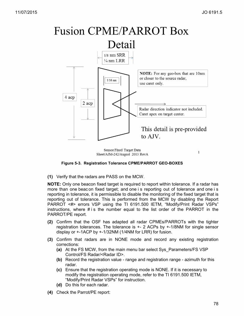
11/07/2015 JO 6191.5
78
Figure 5-3. Registration Tolerance CPME/PARROT GEO-BOXES
(1) Verify that the radars are PASS on the MCW.
NOTE: Only one beacon fixed target is required to report within tolerance. If a radar has more than one beac on fixed target; and one i s reporting out of tolerance and one i s reporting in tolerance, it is permissible to disable the monitoring of the fixed target that is reporting out of tolerance. This is performed from the MCW by disabling the Report PARROT <#> errors VSP using the TI 6191.500 IETM, “Modify/Print Radar VSPs” instructions, where # i s the number equal to the list order of the PARROT in the PARROT/PE report.
(2) Confirm that the OSF has adapted all radar CPMEs/PARROTs with the tighter registration tolerances. The tolerance is +- 2 ACPs by +-1/8NM for single sensor display or +-1ACP by +-1/32NM (1/4NM for LRR) for fusion.
(3) Confirm that radars are in NONE mode and record any existing registration corrections: (a) At the FS MCW, from the main menu bar select Sys_Parameters/FS VSP
Control/FS Radar/<Radar ID>. (b) Record the registration value - range and registration range - azimuth for this
radar. (c) Ensure that the registration operating mode is NONE. If it is necessary to
modify the registration operating mode, refer to the TI 6191.500 IETM, “Modify/Print Radar VSPs” for instruction.
(d) Do this for each radar.
(4) Check the Parrot/PE report:
11/07/2015 JO 6191.5
79
(a) Using the MCW, Select Reports->PARROTs/PE.
(b) Verify that the reliability value for the PARROTs is at least 90.
(c) Select the PRINT or SAVE button.
(5) Verify that the radars are PASS on the MCW. This check may still be accomplished for any PASS radars and perhaps non-PASS per specialists’ discretion.
(6) Using the ABC/QWERTY keyboard, login to a TCW position.
(7) Select the registration alternate map:
(a) Using trackball, select MAPS from the DCB.
(b) Using trackball, select CLR ALL from the DCB.
(c) Using trackball, select DONE from the DCB.
(d) Using the ABC/QWERTY keyboard, select MAPS.
(e) Type the map number assigned to the Alt-Reg map and press <ENTER>.
NOTE: These next steps are not required but will aid in locating the registration boxes.
(f) Using the ABC/QWERTY keyboard, select MAPS.
(g) Type the map number for the fixed target map and press <ENTER>.
(8) Set brightness values:
(a) Using trackball, select BRITE from the DCB.
(b) Using trackball, select MPA from the DCB and set to the max value (100).
(c) Using trackball, select MPB from the DCB and set to the max value (100).
(d) Using trackball, select BCN from the DCB and set to the min value (OFF).
(e) Using trackball, select PRI from the DCB and set to the min value (OFF).
(f) Using trackball, select POS from the DCB and set to the max value (100).
(g) Using trackball, select DONE from the DCB.
(9) Set character size:
(a) Using trackball, select CHAR SIZE from the DCB.
(b) Using trackball, select POS from the DCB and set to the minimum value (1).
(c) Using trackball, select DONE from the DCB.
(10) Set radar site mode targets:
(a) Determine which mode to use for checking targets. For single sensor operations use MULTI. For fused display mode (if available) use FUSED.
(b) Verify current setting of SITE <mode> on the DCB.
(c) If setting already reads SITE MULTI or FUSED then skip to next numbered step.
(d) Using trackball, select SITE <mode> from the DCB.
(e) Using trackball, select MULTI or FUSED from the DCB.
(f) Using trackball, select DONE from the DCB.
11/07/2015 JO 6191.5
80
NOTE: The next step will toggle the fixed target display on and off. You can use this step to help locate the targets. In addition, for sites that are checking fused mode, you can use it to turn targets on and o ff to get a better view of the small fused registration box.
(11) Set RTQC Mode:
(a) Using trackball, select SHIFT from the DCB.
(b) Using trackball, select RTQC from the DCB.
(c) Verify that TT is displayed in the status area, if not select RTQC again.
(d) Using trackball, select DONE from the DCB.
NOTE: The next two steps will verify if the fixed beacon targets are displayed in or on the registration boxes. It is required that at least one fixed beacon target meets the standard. If there is more than one f ixed target and one is in and one is out, this is an indication that the issue is with the test target and not the radar. It is important that all beacon fixed targets and associated radar are well surveyed and positioned before utilizing this procedure or that there is knowledge that there is at least one beacon fixed target for that radar that is reliably surveyed. (12) Verify location of fixed targets. Do the following steps for each fixed target:
(a) Using trackball, select RANGE from the DCB.
(b) Set range large enough to see all fixed targets.
(c) Using trackball, select DONE from the DCB.
(d) Locate a fixed target.
(e) Using trackball, select PLACE CNTR from the DCB.
(f) Using trackball, move fixed target so that it appears near the center of the screen.
(g) Press left button on trackball to set position.
(h) Using trackball, select RANGE from the DCB.
(i) Set range to minimum value.
(j) Using trackball, select DONE from DCB.
(k) If fixed target has moved off center then relocate by adjusting the display using the trackball and DCB PLACE CNTR feature.
(l) For single sensor operations, verify that the beacon fixed target is in, on or touching the outer registration box. Toggle the RTQC button if needed to determine the positioning of the target in reference to the geo-boxes.
(m) For fusion sensor operations, verify that the beacon fixed target is in, on or touching the inner registration box. Toggle the RTQC button if needed to determine the positioning of the target in reference to the geo-boxes.
(13) If discrepancies are found and as sistance is needed, contact STARS Second Level Engineering for registration support. If no discrepancies are found and the fixed targets meet standards, then the procedure is complete. The remainder of this procedure has instructions to optimize the radar alignment and registration.
(14) If it is necessary to optimize the alignment of beacon test target(s) to meet registration standards, first determine which radar requires adjustment.
(a) Bring the display to focus on the box with the out of bound fixed target.

11/07/2015 JO 6191.5
81
(b) Using the trackball, select SITE and then the first radar to the left displayed in the DCB.
(c) The beacon fixed target will only appear for the radar that is assigned to that particular registration box. If the out of bound beacon fixed target is not displayed, select the next radar in the DCB list and continue until the out of bound beacon fixed target appears. Note the radar selected.
(15) Initially, coordinate with AT for notification for all registration corrections. Subsequently, when the facility becomes more confident with these changes, coordinate when applying changes greater than 16/16 ACPS and/or 16/512nm. It is recommended to perform this at low traffic periods but when there are some arrivals to confirm centerline alignment. It is recommended, but optional, to have the assistance of an observer positioned at the display for visual confirmation of any changes.
(16) Determine if the optimization required or desired is in range, azimuth or both and which direction, + or -. If possible, using the known dimensions of the inner and outer box, make an estimate of how much change is required and which direction (+ or -) to center the target in the outer box for single sensor mode or inner box for fusion. Registration parameters can change by 1/512 nm for range, and 1/16 ACP units for azimuth.
NOTE: For assistance with determining if range and/or bias corrections are plus or minus; please call Hardware Field Support for assistance.
(17) At the MCW, follow the TI 6191.500 IETM, “Modify/Print Radar VSPs” instructions, for changing the registration value - range or registration value - azimuth values for the radar determined in step (14). Modify the value by the estimated amount by entering the value in the modify Radar Parameters window. It is recommended to make single unit incremental changes until more experience is obtained.
NOTE: Select CANCEL between each successfully entered correction.
(18) Using targets of opportunity especially arrivals on runway centerlines if available, in the single sensor view of the radar just adjusted, verify with air traffic that targets are performing as expected in proper locations. It may be nec essary to repeat step (17) until AT is satisfied provided test targets meet fixed target map criteria.
(19) If the decision is made to fall back to previous values:
(a) At the FS MCW, select Sys_Parameters/FS VSP Control/Radar ID and select the radar that is being set to previous values.
(b) If not already set to recorded value, highlight the registration value – range line.
(c) Select modify and enter the previously recorded range value.
(d) Select OK.
(e) Select YES in the VSP modification warning window.
(f) Select CANCEL in the FS Radar VSP window.
(g) Perform the same steps as above to change the registration value – azimuth.
(h) If assistance is required, contact Terminal Second Level Engineering, Hardware Field Support.
11/07/2015 JO 6191.5
82
5-18. Summarization Report Check. a. Objective. Verify that STARS CPU processing, memory, network utilization, and radar
tower turnaround rates are reasonable and/or within specified tolerances. b. Discussion. The summarization report presents statistical data for target reports per
target type and f or CPU, memory and net work utilization for each processor in the STARS configuration. When the summarization report is selected, the Summarization Report Selection window is displayed. All fields are modifiable within memory constraints for date and time in relation to the amount of data stored locally. The default duration and interval are one minute and one hour, respectively, and are not configurable. Min, Max, and A vg. values are determined from the interval over the duration period. This report is useful for preventive maintenance and trouble-shooting.
c. Test Equipment Required. Not applicable. d. Conditions. Not applicable.
e. Detailed Procedures. (1) From the MCW of the desired system level, select Reports/ Summarization Report.
(2) If a s pecific time period is desired, enter desired time within the last month or proceed to next step. The default is the last one hour.
(3) Select OK and wait for report to generate.
(4) Check report against Standard and Tolerances in par. 3-17.
5-19. Service Level Switchover. NOTE: Planned switchovers should be coordinated in advance with AT, NOMs (if applicable), and OCC to ensure that all constituent facilities and affected personnel are notified. Inter-facility (IFDT), ADS-B, MLAT, radar ASTERIX (DoD only at the time of this writing) and interfaced third party applications will be temporarily interrupted. Performing the following procedures can impact air traffic operations. If this is a planned activity, it is recommended to perform this check at low traffic periods. Important information to consider is the length of time to remain on the redundant system. Enough time should be considered so that all AIG interfaces and applications can be verified; nominally 30 minutes. It is recommended to develop local procedures for verifying the performance of interfaced third party applications after a switchover. Also consider enough time to execute the bi-annual par. 5-24 Single Service Redundancy procedure. If this is an unplanned event, notification must take place per SOP for unplanned events.
a. Objective. Verify that the currently active service level is functional with indications that input and output data is provided to and from external interfaces.
b. Discussion. STARS service level redundancy uses a m anual device to switch data from one service level to the other. This switch can be made from FS to EFS and/or from EFS to FS.
c. Test Equipment Required. Not applicable. d. Conditions. Determine the operational service level and coordinate with Air Traffic to
determine which service level is desired after the completion of this check. There may be reasons to leave the operational level in EFS or FS.
e. Detailed Procedures. NOTE: Selecting the “FSL (or EFSL) Unavailable” option from the FS (or EFS) Service Level Status window will broadcast a system-wide “Service Level Unavailable” banner on each TCW and TDW display. This feature can be used to notify users of the service level switchover. The level provided depends on t he MCW (FSL/EFSL) used. The service

11/07/2015 JO 6191.5
83
unavailable option can be reached by selecting, Options/Set Mode on the MCW main menu bar.
(1) Verify that the standby service level (SYS1 or SYS2) IFDT, ETMS, and AIG External Interfaces are online.
(2) Check the status of the AIG Routers, AIG External Interfaces, ETMS and I FDT icons at the MCW of the active service level.
(3) Open an I FDT Messages window by selecting, Options/FS IDT Messages from the SYS1 MCW.
(4) Open an IFDT Messages window by selecting, Options/EFS IDT Messages from the SYS2 MCW.
(5) Verify that at minimum outbound IFDT TR (test request) messages are answered by inbound IFDT DT (Data Test) messages on the active service level MCW.
(6) Note that there is no two way IFDT messaging taking place on the standby service level MCW.
(7) Verify that the key lock on the G4 PSSP A/B Gang Switch is in the ON position.
(8) At the front of the G4 PSSP A/B Gang Switch, verify all expected LEDs on t he operational side are lit and steady (IFDT, ETMS, AIG1, AIG2).
(9) On the controller card, verify that the PS1 and PS2 LEDs are both lit.
(10) At the G4 gang switch, toggle the A/B Gang pin to switch the external connections.
(11) At the front of the G4 PSSP A/B Gang Switch, verify all expected LEDs on t he newly active operational side are lit and steady (IFDT, ETMS, AIG1, AIG2).
(12) On the controller card, verify that the PS1 and PS2 LEDs are both lit and steady.
NOTE: It may be necessary to bring IFDT online from the newly active MCW.
(13) Verify that outbound IFDT TR (test request) messages are answered by inbound IFDT DT (Data Test) messages on the newly active service level MCW.
(14) Monitor the AIG Routers and AIG External Interfaces icons at the MCW of the newly active service level. Verify that the external interfaces ETMS and IFDT become PASS/GREEN within a minute or two.
(15) Check the AIG Routers icon at the MCW of the newly standby service level. Verify that the minimum required routers interfaces for supporting external AIG applications are DEGRADED/YELLOW. Verify that the external AIG applications, the external interfaces IFDT, and ETMS are FAIL/RED.
(16) To return to original configuration, from the G4 gang-switch toggle the A/B pin to enable the standby external connections.
(17) Check the AIG Routers and A IG External Interfaces icons at the MCW of the original active service level. Check the external interfaces ETMS and IFDT. Verify that the applicable interfaces are PASS/GREEN.
(18) Notify the OCC that the check is complete and external interfaces are restored.
(19) Notify Air Traffic that service is returned and strongly recommend a RESTORE BASE from Center.
(20) Cancel the IFDT Messages window on the SYS1 and SYS2 windows.
(21) If the switchover is from ESFL to FSL, it is recommended to perform a system restart on the EFSL service level only.
11/07/2015 JO 6191.5
84
(22) Ensure that the IFDT is taken offline from the MCW on the non-operational service level.
5-20. Leap Second Check. a. Objective. Verify the STARS system time is not compromised by leap second
adjustments by comparing it to another time source that uses Coordinated Universal Time (UTC).
b. Discussion. Time may drift or differ from UTC due to defective equipment, improper settings, or using less accurate devices, but a t ypical time deficiency could be introduced by occasional GPS leap second adjustments. STARS system inputs and internal processing, particularly ADS-B, PRM-A and ASR-11 ASTERIX functions, require precision timing to avoid automated functions from discarding valid data inputs that fall outside of adapted bounds due t o time deficiencies. Therefore, STARS specialists must periodically verify UTC time with other UTC GPS time sources. Although not the only cause for time deficiencies, GPS leap second adjustments may occur up to two times a year, at the end of June and/or December. Leap seconds are added to keep the difference between UTC and astronomical time (UT1) to less than 0.9 seconds. The International Earth Rotation and Reference Systems Service (IERS) measures the Earth’s rotation and publishes differences between UTC and UT1.
c. Test Equipment Required. Access to an independently verified GPS time source. The following are suggestions: Dynamically updated UTC time is provided at http://www.time.gov/; then select the UTC time zone. The National Institute of Standards and Technology maintains a time line toll number, (303) 499-7111 that announces the UTC time each minute and has a tick sound to mark each second. Sites may also check against another verified facility GPS time source, or call an outside facility with a verified GPS time source as a reference.
d. Conditions. If there is a c urrent deficiency, some if not all of the following error notification messages may be obs erved in the MCW message log: #206 T ime Adjustment Too Large, #207 T ime Difference Out of Range, #327 TRS Time Flywheeling or other time deficiency errors. Refer to TI6191.404, SSMD for additional STARS system message information about time and G PS deficiencies. It is possible that no time error messages are observed if UNIX and GPS UTC time are all incorrect but agree with each other. There could also be ADS-B, PRM-A and/or ASR11 ASTERIX data rejects due to time errors as well. Therefore, it is important for STARS specialists to perform this check periodically.
e. Detailed Procedure. (1) Check for leap second bulletins. To receive leap second bulletins, register for class
C notifications at:
http://hpiers.obspm.fr/eop-pc/products/bulletins/bulletin_registration.html. (2) At the MCW verify that the GPS icon is PASS/GREEN or that in the GPS Detailed
Status the Interface State is ONLINE and either the Main or Alternate GPS Heartbeat and GPS Status is PASS/GREEN.
(3) Check the time field on the MCW and verify the correct system day, month and year.
NOTE: If the system year is incorrect, do not restart the service level until the system year date is correct.
(4) Check the MCW for any current time, rejection of ADS-B or ASR-11 ASTERIX error indications.
11/07/2015 JO 6191.5
85
(5) At GPS1, verify that the colon indicators in the front panel LED lights are on and steady and the Fail indicator is not lit.
(6) At GPS2, verify that the colon indicators in the front panel LED lights are on and steady and the Fail indicator is not lit.
(7) Verify the GPS time with another GPS source. It may be necessary to have assistance to perform this check. The times should be w ithin one second. Reference the Test Equipment Required, Section c of this paragraph, for resources to use to verify GPS time is correct.
(8) Verify if the system time is consistent with the GPS UTC time by comparing the GPS clock with the clock time displayed on the MCW. It may be necessary to have assistance to perform this check. The times should be within one second.
(9) If any time discrepancies are found, notify STARS Second Level Engineering support.
5-21. G4 Gang Switch Check. a. Objective. Verify that the gang switch LEDs have proper indication.
b. Discussion. The STARS G4 PSSP A/B Gang Switch (G4 Pro Switching System Plus) switches IFDT, ETMS, and ex ternal client AIG data between FSL/SYS1(A) to EFSL/SYS2(B). It is a critical redundancy component in the event of a catastrophic service level failure that would require a full transition to the standby service level. The G4 PSSP gang switch is capable of passing through data even if the unit has lost power. However, there is no indication at the MCW that the unit has failed. Therefore visually checking the LED array is required.
c. Test Equipment Required. Not applicable.
d. Conditions. Not applicable.
e. Detailed Procedures. (1) Verify that the key lock on the G4 PSSP A/B Gang Switch is in the ON position.
(2) At the front of the G4 PSSP A/B Gang Switch, verify all expected LEDs on the operational side are lit and steady (IFDT, ETMS, AIG1, AIG2).
(3) Verify that the PS1 and PS2 LEDs are lit and steady.
5-22. Resource Verification. a. Objective. Verify that the minimum required resources that can sustain ATC
operations are present and working properly. b. Discussion. The resource verification tests available resources (CGWs, RDPSs,
MCWs, CDRs, TCWs, TDWs, SSS, SIM, GPWs) with a bat tery of hardware, communication, and software check sum and version online tests. Results are displayed on the report and are iconic; drill down for additional information.
c. Test Equipment Required. Not applicable. d. Conditions. The certifying official must ensure that the correct versions of software
and adaptation are installed and running on each processor utilized in the system. FSL and EFSL have three software and t hree adaptation directories. One of the checks Resource Verification performs is that the software and adaptation on each processor match within each directory, version, and checksum. Verify that the minimum required resources that can sustain the facility AT operation pass.
11/07/2015 JO 6191.5
86
e. Detailed Procedures. Perform the Resource Verification test from the FSL or EFSL MCW by selecting Diagnostics/Resource Verification.
5-23. STARS Procedure for Full Performance Verification. a. Objective. Verify the ability of FS STARS to process and di splay aural and v isual
alarms in support of terminal air traffic control operations, and v erify RTQC recieve status.
b. Discussion. The alarms include special condition codes and safety alert alarms i.e., MSAW and CA. Radar RTQC radar monitor is also part of the PVER. The full performance verification scenario is initiated at the MCW and observed at a display position. The RTQC radar monitor portion is performed internally in the RDP and is verified only from the MCW. The required number of displays to be c hecked will be determined locally. However, as a m inimum, one TCW shall be c hecked. This check should be made on a different position than last executed if possible.
NOTE: During image upgrade activities, or any similar activities, the performance verification is used to verify certain system components that may be altered by the activity. ATCoach, display aural and v isual processing, are primary examples of components that could be changed by new images. NOTE: Expected results for full PVER is that all ASSERTIONS are processed with STATUS PASS. If FAILS are noted or all ASSERTIONS not completed, rerun PVER. If errors persist, contact your OSF.
(1) Full PVER: There are three basic processing functions that are tested by the Full PVER. They are special condition codes, safety alert, and RTQC threshold monitoring. The special condition codes and the safety alerts implement aural and visual alarms that are observed at a display position within the first four minutes of the PVER. The RTQC monitoring tests have no display. O nce the PVER is requested, the following items provide guidelines on t he execution and results analysis of the Full FS PVER;
(a) A successful execution of the PVER is indicated on the PVER test report by an end of test notification specifying the duration of the test, as well as, confirmation that the proper indications are displayed. The specialist should inspect the “Test Case Summary” at the bottom of the Performance Verification Test Report to ensure all expected test cases were processed. A discrepancy between these numbers may indicate a problem with the PVER scenario, the execution of the scenario, or the system data processing and display. I f this occurs print the report, and retry the scenario. If the discrepancy reoccurs, print the second report and contact the assigned OSF.
(b) If the failures indicate an RTQC receive status failure (Beacon/Search RTQC, PARROT or PE), verify that RTQC monitoring threshold is performing within standards.
(c) If the failures pertain to special condition codes or safety alert processing it is acceptable to rerun the PVER scenario and make visual confirmation that the situation displayed is performing as expected. It is permissible to corroborate with AT to determine if system is performing as expected using targets of opportunity.
(d) If the discrepancy reoccurs, print the second report and contact the assigned OSF.
(e) The following definitions are useful to determine pass/fail criteria of the system performance verification:
11/07/2015 JO 6191.5
87
1. ASSERTIONS – Boolean test cases scripted into the scenario that report as PASS or FAIL and both the expected and actual results of the test case.
2. ACTUAL – The column that reports the result condition of an assertion.
3. STATUS – This column only lists the Boolean result of an assertion. The values are only PASS or FAIL.
4. EXPECTED – Number of assertions scripted into the PVER scenario and also the column that specifies the pass condition of an assertion.
5. PROCESSED – Actual number of assertions processed in the PVER scenario
6. REJECTED – This indicates assertions that are rejected due to logic errors, undefined fixes, aircraft type, timing, etc. Rejections are typically errors with the PVER scenario.
7. MISSING – The difference between the expected assertions and the actual number of processed assertion statements.
8. EXTRA – Any additional assertion statements processed but are not listed in the scenario.
9. NOTP – Not present, is used to test or report the absence of special condition codes.
10. MISS – Similar to NOTP but used with RTQC assertions.
11. EXEC – Excessive is used to test or report excessive RTQC.
12. CURR – Current is used with CA and MSAW assertions and defines the aircraft situation as being in present violation of separation rules or low altitude parameters, respectively, as opposed to PRED.
13. PRED – Prediction indicates future CA or MSAW violations unless course, speed, or altitude is changed to mitigate safety transgressions.
(2) Targets of opportunity may be us ed to verify processing and di splay of special condition codes and safety alert alarms. It is permissible to corroborate with AT to perform this check. Lack of user complaints is an acceptable method of coordination provided that AT is advised to report any issues with visual and aural alarms.
(3) The MCW has been modified to provide a drop-down list of performance scenarios. They are selectable and can be adapted for specific purposes. Contact your OSF for more information on default scenarios and/or requests for additional specific scenarios. Keep in mind that not all developed scenarios may provide assertions for MCW reporting. For ADSS certain scenarios are provided that are adapted with assertions that provide an M CW summary reports and use ASTERIX formatted input. The SENSOR_fs_pv_scen is used to check the ADS sensor status reporting, SPC_ADS_pv_scen is used to check special conditions codes provided from the ADS, GRNDSTA_pv_scen is used for checking ground station status.
NOTE: PVER scenarios may be modified to reflect local site conditions or preferences. The detailed procedures specified in this section may not apply. If this is the case, sites must develop local procedures for executing PVER scenarios.
c. Test Equipment Required. ATCoach PVER scenario provided by first-level support. The TTSE must be online and available and ATCoach must be in ready state on the TTSE.
11/07/2015 JO 6191.5
88
d. Conditions. The display selected for PVER may not have airspace and only one PVER may execute at a time. The PVER check includes visual and aural confirmation that the alarms perform as expected. For single display radar towers only, if release of the display impacts AT, then results noted from the report and/or lack of error reports from qualified operators are acceptable. Checks for remote or distant positions may require assistance. If assistance is not available, or if the site is unable to release positions, then targets of opportunity with lack of user complaints is an ac ceptable method of performing this check.
e. Detailed Procedures. (1) PVER is performed on display positions that do not have airspace. Checking if a
display has airspace or no airspace can be done in the following ways: (a) At the MCW, drill down into the display detailed status window and verify that
the “Equipment State” is in STANDBY. (b) Use the “View Consolidation” report on the MCW. I f all the keyboard
identifiers assigned to a T CW/TDW are blank under the TCP column, the position has no airspace.
(c) Observe the System Status Area (SSA) on t he TCW/TDW. I f consolidation information in field S is blank, the position has no airspace. “1R CON: 1R” is an example of consolidation information in field S.
(2) If the chosen position has airspace, the airspace is reassigned using the following commands at a TCW/TDW. (a) Login any display position if not already logged-in.
(b) Enter the command, <F7 C (receiving keyboard) (sending keyboard) +><Enter>, where the sending keyboard position is the one s elected for PVER.
(3) From the MCW, execute the Performance Verification on the TCW/TDW by selecting the FS PVER from the drop down list.
(4) The display position will blank momentarily as it transitions into the PVER mode. (5) As the scenario runs, ensure that the following codes and/or special condition
acronyms are properly identified and displayed.
NOTE: In fused mode only the 2 letter condition is displayed.
(a) HJ (High-jack) 7500
(b) RF (Radio Failure) 7600
(c) EM (Emergency) 7700
(d) LA/MSAW (Low Altitude)
(e) CA (Conflict Alert)
(6) If using the abbreviated method for this check, the specialist may cancel the scenario now by selecting <CANCEL> on the PVER window, then selecting <CLOSE> when that option changes from a grayed-out state.
(7) Report must be printed or electronically saved (par.5-83) if save option is available, (full PVER or shortened version of PVER available if the OSF has adapted this as an option available at the MCW ) and retain for your records per 6000.15 direction. A successful test is accomplished by observing the indications listed in step 5 and/or observing on the report that all test cases executed (no REJECTIONS), and
11/07/2015 JO 6191.5
89
all PASSed. The exception to this direction is if the abbreviated PVER is run or if targets of opportunity are used to conduct this check.
(8) After the test is completed, verify that all beacon and search RTQC test cases have a “PASS” status, all PARROT and PE test cases have a “PASS” status, all Special Code (SPC) test cases have a “PASS” status, and Test Report Summary indicates all test cases “PASS.”
(9) If the site is ADS-B capable, see par.5-38 for detailed procedures for running the ADSS performance verifications. O therwise at the satisfactory completion of the PVER, return the display to normal operational capability.
NOTE: It may be necessary to ensure that ADS sensor and RTQC are selected.
(10) At the completion of the previous scenario, select the SENSOR_fs_pv_scen from the PVER dropdown list. At the completion of the scenario, verify that all test cases completed and are pass.
(11) At the completion of the previous scenario, select the GRNDSTA_fs_pv_scen from the PVER dropdown list. At the completion of the scenario, verify that all test cases completed and are pass.
(12) At the completion of the previous scenario, select the SPC_fs_pv_scen from the PVER dropdown list. Verify the display of special condition codes and/or special condition acronyms on the selected display. A t the completion of the scenario, verify that all test cases completed and are pass.
(13) Return the display to normal operational capability.
5-24. Single Service Resource Redundancy. a. Objective. Verify that standby resources and isolated data paths are available and
capable of resuming operations seamlessly. This procedure is designed to isolate and test individual data paths within a single service level i.e., FSL or EFSL, as well as verify that standby processors are hot-standby. This check is limited to AIG, LAN, NUNIO, CGW, and RDP equipment in a single service level.
b. Discussion. Within each service level there is redundancy on a resource level. Data path equipment (AIG, LAN, NUNIO, CGW, and RDP) are duplicated and behave as hot-standbys. The active and standby equipment for the AIG, LAN, NUNIO, CGW, and RDP resources must be onl ine and available. See Table 5-3 at the end of the procedure to reference the equipment states as the procedure progresses. Schedule and coordinate with AT if necessary, to perform this check on both FSL/SYS1 and EFSL/SYS2.
c. Test Equipment Required. Not applicable. d. Conditions.
(1) Prior to performing this procedure, the ATSS must verify the status of the standby resources. Verify that the minimum required modules in both primary and alternate NUNIOs that can sustain the facility AT operation are available. If this is not known, confer with AT to determine the minimum sensor requirements to sustain operations. Verify that AIG, LAN, NUNIO, CGW, and RDP are online and ar e displaying proper indications at the MCW.
(2) This check is performed on both service levels but it may be scheduled at different times. It is necessary to notify AT (for example if FSL/SYS1 service level is tested, coordination with AT to move to EFSL is necessary). It is recommended to perform this procedure at low traffic periods.
e. Detailed Procedure. Perform the procedure at the non-operational MCW.
11/07/2015 JO 6191.5
90
NOTE: When returning NUNIOs back to an online state; any and all ASR-11 sensors must have their alternate feeds returned to ONLINE manually. This is done by selecting the Sys Control > FS/EFS Interface Control > FS/EFS Sensor then select the ASR11 sensor from the FS/EFS Interface Selection list. From the FS/EFS Sensor Interface Control select and ensure both Main and Alternate Feed buttons are Online.
(1) Path #1 (a) Take LAN B offline at the MCW from Sys Control/LAN Control/LAN Offline on
the main menu bar.
(b) Reconfigure all alternate NUNIO (NUN-A) modules offline at the MCW from the Sys Control/Interface Control/NUNIO Offline.
(c) Reconfigure offline the alternate AIG External Interfaces from the MCW by selecting Sys Control/Interface Control/All AIG Out External Interfaces/ALTERNATE Feed Offline.
NOTE: If available the ADS sensor (or any applicable Ethernet surveillance input) is listed in the All External Interfaces list but does not change status with this command. ADS and other AIG surveillance data is taken offline or online individually using the AIG External Interfaces command.
(d) Reconfigure the alternate ADS offline from the MCW by selecting Sys Control/Interface Control/AIG External Interfaces/select the ADS sensor AIG/ALTERNATE Feed OFFLINE.
(e) Reconfigure CGW2 and RDP2 offline at the MCW from Sys Control/Resource Control/Reconfigure Offline.
(f) Ensure that all remaining resources are online and check a display to verify there is no interruption to AT service.
(2) Path #2 (a) Return LAN B back online from the MCW using Sys Control/FS LAN
Control/LAN Online. Wait until the LAN icon returns green. (b) Take LAN A offline at the MCW from Sys Control/LAN Control/LAN Offline on
the main menu bar. (c) Ensure that all remaining resources are online and check a display to verify
there is no interruption to AT service.
(3) Path #3 (a) Reconfigure online the alternate AIG External Interfaces from the MCW by
selecting Sys Control/Interface Control/All AIG External Interfaces/ALTERNATE Feed ONLINE.
(b) Reconfigure the alternate ADS online from the MCW by selecting Sys Control/Interface Control/AIG External Interfaces/select the ADS sensor AIG/ALTERNATE Feed ONLINE.
(c) Reconfigure all alternate NUNIO (NUN-A) modules online at the MCW from the Sys Control/Interface Control/NUNIO Online.
(d) Reconfigure all primary NUNIO (NUN-P) modules offline at the MCW from the Sys Control/Interface Control/NUNIO Offline.
(e) Reconfigure offline the primary AIG External Interfaces from the MCW by selecting Sys Control/Interface Control/All AIG Out External Interfaces/MAIN Feed OFFLINE.
11/07/2015 JO 6191.5
91
(f) Reconfigure the primary ADS offline from the MCW by selecting Sys Control/Interface Control/AIG External Interfaces/select the ADS sensor AIG/MAIN Feed OFFLINE.
(g) Ensure that all remaining resources are online and check a display to verify there is no interruption to AT service.
(4) Path #4 (a) Reconfigure CGW2 online at the MCW from Sys Control/Resource
Control/Reconfigure Online.
(b) Reconfigure CGW1 offline at the MCW from Sys Control/Resource Control/Reconfigure Offline.
(c) Ensure that all remaining resources are online and check a display to verify there is no interruption to AT service.
(5) Path #5 (a) Reconfigure RDP2 online at the MCW from Sys Control/Resource
Control/Reconfigure Online. (b) Reconfigure RDP1 offline at the MCW from Sys Control/Resource
Control/Reconfigure Offline. (c) Ensure that all remaining resources are online and check a display to verify
there is no interruption to AT service. (6) Path #6
(a) Return LAN A back online and wait until the LAN Reconfiguration Confirm popup is observed from the MCW using Sys Control/FS LAN Control/LAN Online.
(b) Take LAN B offline at the MCW from Sys Control/LAN Control/LAN Offline on the main menu bar.
(c) Ensure that all remaining resources are online and check a display to verify there is no interruption to AT service.
(7) Path #7 (a) Reconfigure online the main AIG External Interfaces from the MCW by
selecting Sys Control/Interface Control/All AIG External Interfaces/MAIN Feed ONLINE.
(b) Reconfigure the main ADS online from the MCW by selecting Sys Control/Interface Control/AIG External Interfaces/select the ADS sensor AIG/MAIN Feed ONLINE.
(c) Reconfigure all primary NUNIO (NUN-P) modules online at the MCW from the Sys Control/Interface Control/NUNIO Online.
(d) Reconfigure all alternate NUNIO (NUN-A) modules offline at the MCW from the Sys Control/Interface Control/NUNIO Offline.
(e) Reconfigure offline the alternate AIG External Interfaces from the MCW by selecting Sys Control/Interface Control/All AIG External Interfaces/ALTERNATE Feed OFFLINE.
(f) Reconfigure the alternate ADS offline from the MCW by selecting Sys Control/Interface Control/AIG External Interfaces/select the ADS sensor AIG/ALTERNATE Feed OFFLINE.
11/07/2015 JO 6191.5
92
(g) Ensure that all remaining resources are online and check a display to verify there is no interruption to AT service.
(8) Path #8 (a) Reconfigure CGW1 online at the MCW from Sys Control/Resource
Control/Reconfigure Online.
(b) Reconfigure CGW2 offline at the MCW from Sys Control/Resource Control/Reconfigure Offline.
(c) Ensure that all remaining resources are online and check a display to verify there is no interruption to AT service.
(9) Path #9 (a) Reconfigure RDP1 online at the MCW from Sys Control/Resource
Control/Reconfigure Online.
(b) Reconfigure RDP2 offline at the MCW from Sys Control/Resource Control/Reconfigure Offline.
(c) Ensure that all remaining resources are online and check a di splay to verify there is no interruption to AT service.
(10) Path #10 End of Check. (a) Return LAN B back online and wait until the LAN Reconfiguration Confirm
popup is observed from the MCW using Sys Control/FS LAN Control/LAN Online.
(b) Reconfigure online the alternate AIG External Interfaces from the MCW by selecting Sys Control/Interface Control/All AIG External Interfaces/ALTERNATE Feed ONLINE.
Reconfigure the alternate ADS online from the MCW by selecting Sys Control/Interface Control/AIG External Interfaces/select the ADS sensor AIG/ALTERNATE Feed ONLINE.
(c) Reconfigure all alternate NUNIO (NUN-A) modules online at the MCW from the Sys Control/Interface Control/NUNIO Online.
(d) Reconfigure CGW2 and RDP2 online at the MCW from Sys Control/Resource Control/Reconfigure Online.
(e) Ensure that all remaining resources are online and check a display to verify there is no interruption to AT service.
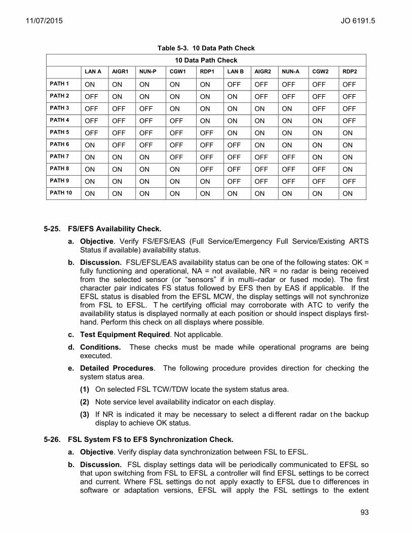
11/07/2015 JO 6191.5
93
Table 5-3. 10 Data Path Check
10 Data Path Check
LAN A AIGR1 NUN-P CGW1 RDP1 LAN B AIGR2 NUN-A CGW2 RDP2
PATH 1 ON ON ON ON ON OFF OFF OFF OFF OFF PATH 2 OFF ON ON ON ON ON OFF OFF OFF OFF PATH 3 OFF OFF OFF ON ON ON ON ON OFF OFF PATH 4 OFF OFF OFF OFF ON ON ON ON ON OFF PATH 5 OFF OFF OFF OFF OFF ON ON ON ON ON PATH 6 ON OFF OFF OFF OFF OFF ON ON ON ON PATH 7 ON ON ON OFF OFF OFF OFF OFF ON ON PATH 8 ON ON ON ON OFF OFF OFF OFF OFF ON PATH 9 ON ON ON ON ON OFF OFF OFF OFF OFF PATH 10 ON ON ON ON ON ON ON ON ON ON
5-25. FS/EFS Availability Check. a. Objective. Verify FS/EFS/EAS (Full Service/Emergency Full Service/Existing ARTS
Status if available) availability status.
b. Discussion. FSL/EFSL/EAS availability status can be one of the following states: OK = fully functioning and operational, NA = not available, NR = no radar is being received from the selected sensor (or “sensors” if in multi–radar or fused mode). The first character pair indicates FS status followed by EFS then by EAS if applicable. If the EFSL status is disabled from the EFSL MCW, the display settings will not synchronize from FSL to EFSL. T he certifying official may corroborate with ATC to verify the availability status is displayed normally at each position or should inspect displays first-hand. Perform this check on all displays where possible.
c. Test Equipment Required. Not applicable.
d. Conditions. These checks must be made while operational programs are being executed.
e. Detailed Procedures. The following procedure provides direction for checking the system status area.
(1) On selected FSL TCW/TDW locate the system status area.
(2) Note service level availability indicator on each display.
(3) If NR is indicated it may be necessary to select a di fferent radar on t he backup display to achieve OK status.
5-26. FSL System FS to EFS Synchronization Check. a. Objective. Verify display data synchronization between FSL to EFSL.
b. Discussion. FSL display settings data will be periodically communicated to EFSL so that upon switching from FSL to EFSL a controller will find EFSL settings to be correct and current. Where FSL settings do not apply exactly to EFSL due t o differences in software or adaptation versions, EFSL will apply the FSL settings to the extent
11/07/2015 JO 6191.5
94
reasonable. The number of displays to check should be determined locally but at minimum perform this check on one display. Try to use a di fferent display when this check is performed, including standby positions. It is permissible to collaborate with air traffic to perform or verify this check.
c. Test Equipment Required. Not applicable.
d. Conditions. The display has been i n FSL for at least 90 s econds in addition to the following conditions: the display is not frozen, both systems are in the same partition, and neither is configured for playback. Both systems are in normal mode and Service Level Availability is “available”.
e. Detailed Procedures.
(1) In some cases the EFSL IFDT must be offline for synchronization to work. (See Par. 4-2j).
(2) On selected FSL TCW/TDW locate the system status area.
(3) Note availability indicator for display as OK/OK.
(4) At a TCW, ensure the display has been in FSL for at least 90 seconds. Select the <FS> button on the Display Control Panel (DCP) if necessary.
(5) Note just a few of the following FSL synchronization items:
(a) Range
(b) Center/Off-Center selection and locations
(c) Range Ring selection and location
(d) Weather level selections
(e) Brightness levels including enable/disable
(f) Site selection including Fused display mode
(g) Map selections
(h) Character size selection for lists, data blocks, position symbols, and tools
(i) DCB enable/disable and screen edge selection
(j) History trail count and update rate selection
(k) Leader length selection
(l) Cursor speed value and home/no-home selection
(m) Altitude filter limits
(n) Beacon select code banks
(o) Display selections for Uncorrelated and Mapped Uncorrelated radar data
(p) TCP adapted regional altimeter settings
(q) System Status Area location
(r) Preview Area locations
(s) Flight list locations
(t) Preview Area message time out enable/inhibit setting
(u) Audio volume level setting (excluding voice level)
(v) PTL length and setting

11/07/2015 JO 6191.5
95
(w) Auto Label Positioning enable/disable
(x) Test Target enable/disable
(y) ADS indicators enable/disable for the TCP
(z) Data block leader line default positions
(aa) Parallel Approach Monitoring (PAM) enable/disable
(bb) Dwell enable/disable
(cc) Individual TCP Quicklook selections
(dd) User sign-on at each keyboard
(6) Wait at least 10 seconds then switch display to EFS by selecting the ES button on the DCB.
(7) Compare noted items to EFS display data and verify items synchronized.
(8) Switch back to FS.
(9) If necessary, perform a restore to default display settings from the keyboard by selecting <F7> K <ENTER>.
5-27. System Status Alert Color Check. a. Objective. Verify that the red color is properly displayed in the system status alert icon
on display positions.
b. Discussion. The Red Check symbol (solid inverted red delta centered in a g reen outlined box) is always displayed to verify color red is OK. Following the check symbol is either an em pty field which means there are no unavailable or failing radars, or it shows one or more three character radar names (in red) of unavailable or failing radars.
The certifying official may corroborate with ATC to verify the red check symbol at each position. In addition, the official should inspect displays first-hand. Perform this check on all displays where possible.
c. Test Equipment Required. Not applicable.
d. Conditions. These checks must be made while operational programs are being executed.
e. Detailed Procedures. The following procedure provides direction for checking the system status area.
(1) On selected TCW/TDW locate the system status area. Use the “Move SSA” command, “F7 S <slew-enter>” to move SSA to a visible location if necessary.
(2) Verify that in the upper left hand corner of the system status area there is a red-check symbol centered in a green outline box.
5-28. IFDT Processing Input/Output Check. a. Objective. Verify ability of STARS to communicate with other facilities in support of
Terminal Air Traffic operations utilizing IFDT. b. Discussion. IFDT provides data to one service level. For sites upgraded from CARTS
to G4 STARS, the IFDT must be taken offline on the standby system (SYS1 or SYS2) at the MCW or display synchronization does not function properly. For IFDT error messages, reference IFDT error messages and alarms in TI 6191.404, STARS System Message Dictionary from IETM TI 6191.500.
c. Test Equipment Required. Not applicable.
11/07/2015 JO 6191.5
96
d. Conditions. These checks are made on the operational system level, SYS1 or SYS2. e. Detailed Procedures.
(1) Perform this check on the active, operational system.
(2) At the MCW, verify that the NUNIOS icon is GREEN/PASS. If the icon is not GREEN/PASS, drill down into the NUNIO icon by selecting the following icon buttons; NUNIO/NUN-P1/Module 6 and NUNIO/NUN-A1/Module 6. Verify that the Heartbeat, Module State, Module Status, and Zxx, where xx is the last 2 letters of center ID, are GREEN. Heartbeat and Module State should read PRESENT and ONLINE respectively.
(3) At the MCW, verify that the IFDT icon is GREEN/PASS.
(4) Optionally, display the IFDT messages window by selecting, Options/IFDT Messages.
(5) Verify that at minimum there are OUT TR | TEST (Test Request) and reciprocating IN DT | TEST (Data Test) messages during low communication periods or busier IFDT data e.g., FP, DA, DM etc. transmissions.
5-29. Procedure for Abbreviated Performance Verification Check Initiated from the MCW. a. Objective. Verify the ability of STARS to process and display aural and visual alarms
in support of terminal air traffic control operations using an abb reviated performance verification initiated from the MCW.
b. Discussion. The abbreviated PVER includes checks to verify special condition codes and safety alert processing. At minimum, perform this check on one display but a different one than last time, if possible, including standby and/or lesser used positions.
c. Test Equipment Required. ATCoach PVER scenario is in adaptation provided by first-level support. The scenario should be named @@@_ABBR_SCEN, where @@@ is a 3 alphanumeric facility identifier. Please contact your OSF to create an abbreviated PVER with that name for the scenario and the drop down selection. The TTSE must be online and available and ATCoach must be in ready state on the TTSE.
d. Conditions. The display selected for PVER can not have airspace. e. Detailed Procedures. NOTE: Remote positions require assistance. If assistance is not available, then reference par. 3-12d and par.5-30 abbreviated PVER from position, or par. 3-51 targets of opportunity with lack of user complaints.
(1) Abbreviated PVER is performed on display positions that do not have airspace. Checking if a display has airspace or no airspace can be done in the following ways: (a) At the MCW, drill down into the display detailed status window and verify that
the “Equipment State” is in STANDBY. (b) Use the “View Consolidation” report on the MCW. I f all the keyboard
identifiers assigned to a T CW/TDW are blank under the TCP column, the position has no airspace.
(c) Observe the System Status Area (SSA) on the TCW/TDW position. If consolidation information in field S is blank, the position has no airspace. “1R CON: 1R” is an example of consolidation information in field S.
(2) If the chosen position has airspace, the airspace is reassigned using the following commands at a TCW/TDW.
11/07/2015 JO 6191.5
97
(a) Login any display position if not already logged-in.
(b) Enter the command, <F7 C (receiving keyboard) (sending keyboard) +><Enter>, where the sending keyboard position is the one s elected for PVER.
(3) From the MCW, execute the Performance Verification on the TCW/TDW by selecting the FS PVER from the drop down list.
(4) The display position will blank momentarily as it transitions into the PVER mode. (5) As the scenario runs and the display is available, t he following codes and/or
special condition acronyms will be displayed. (a) HJ (High-jack) 7500
(b) RF (Radio Failure) 7600
(c) EM (Emergency) 7700
(d) LA/MSAW (Low Altitude)
(e) CA (Conflict Alert)
NOTE: Mode 3/A codes are not identical in Fused display mode.
(6) Allow the scenario to finish normally and v erify the report has no failures or rejections.
(7) If the site is ADS-B capable, Par. 5-38 has information for running the ADSS performance verification.
(8) Return the display to normal operational capability. Restore airspace if necessary.
5-30. Procedure for Abbreviated Performance Verification Check Using Target Generator. NOTE: Know the name and location on the simulator of the proper site file and abbreviated PVER scenario to execute. Contact the OSF if assistance is needed. Before inputing a training number coordinate with air traffic training for a nu mber that is not used or is available to use for PVER purposes.
a. Objective. Verify the ability of FS STARS to process and di splay aural and v isual alarms in support of terminal air traffic control operations using an abbr eviated performance verification executed using target generator <TG> commands at position.
b. Discussion. The abbreviated PVER includes checks to verify special condition codes and safety alert processing. The PVER scenario must be in a directory on the simulation processor that is selectable from a di splay position in training mode. This option permits specialists to execute the PVER at position. A PVER scenario called from a display position using target generator commands must be observed. At minimum, perform this check on one display but a different one than last time, if possible, including standby and/or less used positions.
c. Test Equipment Required. ATCoach PVER scenario is in adaptation provided by first-level support. The scenario should be named @@@_ABBR_SCEN, where @@@ is a 3 alphanumeric facility identifier. Please contact your OSF to create an abbreviated PVER with that name for the scenario. The TTSE must be onl ine and available and ATCoach must be in a ready state on the TTSE.
d. Conditions. The display selected for PVER can not have airspace. e. Detailed Procedures.
(1) Ensure that the OSF has provided a PVER scenario on t he TTSE (SIM box, or simulator) as part of the adaptation load.
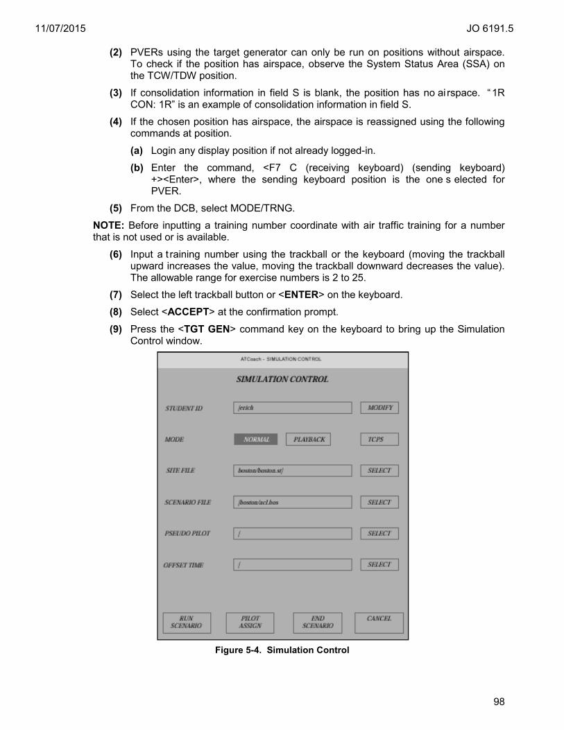
11/07/2015 JO 6191.5
98
(2) PVERs using the target generator can only be run on positions without airspace. To check if the position has airspace, observe the System Status Area (SSA) on the TCW/TDW position.
(3) If consolidation information in field S is blank, the position has no ai rspace. “1R CON: 1R” is an example of consolidation information in field S.
(4) If the chosen position has airspace, the airspace is reassigned using the following commands at position. (a) Login any display position if not already logged-in.
(b) Enter the command, <F7 C (receiving keyboard) (sending keyboard) +><Enter>, where the sending keyboard position is the one s elected for PVER.
(5) From the DCB, select MODE/TRNG.
NOTE: Before inputting a training number coordinate with air traffic training for a number that is not used or is available.
(6) Input a t raining number using the trackball or the keyboard (moving the trackball upward increases the value, moving the trackball downward decreases the value). The allowable range for exercise numbers is 2 to 25.
(7) Select the left trackball button or <ENTER> on the keyboard.
(8) Select <ACCEPT> at the confirmation prompt.
(9) Press the <TGT GEN> command key on the keyboard to bring up the Simulation Control window.
Figure 5-4. Simulation Control
11/07/2015 JO 6191.5
99
(10) Select a site file by clicking the <SELECT> texticon to the right of the SITE FILE selection box and br owse for the site file if necessary. Double click for the selection to occur. The site file should match the current environment adaptation e.g., xxx_ENV001_ad.st, where xxx is the 3 alphanumeric site ID. It is recommended to follow a nomenclature that clearly labels the abbreviated scenario e.g., abbrv_perf_scen.xxx, where xxx is the 3 letter site ID. The site file should be located in the /opt/UFAtpro/site directory.
(11) Select the scenario by clicking the <SELECT> texticon to the right of the SCENARIO selection box and browse for the site file. The scenario should be located in the /opt/UFAtpro/scenario directory as @@@_TWR_SCEN, where @@@ is a 3 alphanumeric identifier. Select by double-clicking.
(12) Select the <RUN SCEANRIO> texticon to start scenario.
(13) As the scenario runs, ensure that the following codes and/or special condition acronyms are properly identified and displayed. (a) HJ (High-jack) 7500
(b) RF (Radio Failure) 7600
(c) EM (Emergency) 7700
(d) LA/MSAW (Low Altitude)
(e) CA (Conflict Alert)
NOTE: Mode 3/A codes are not identical in Fused display mode.
(14) When scenario is complete, enter <TGT GEN> key to bring up the SIMULATION CONTROL window.
(15) Select the <END SCENARIO> texticon to end the scenario.
(16) Select the <CLEAR> key to remove window from display.
(17) Return the display to normal operational capability. Restore airspace if necessary.
5-31. Tower Radar to Display Check. a. Objective. Check that a radar test target is displayed at an expected position on tower
displays.
b. Discussion. This check verifies that a radar test target is displayed at an expected position on t he TDW. This check is required on one display, for one t est target, at minimum. The certifying official may corroborate with a qualified observer to verify this check. This check should be made on different positions than last executed if possible. If no radar test targets are available for display it is permissible to perform visual checks using RTQC or targets of opportunity (see par. 5-34).
c. Test Equipment Required. Not applicable.
d. Conditions. These checks must be made while the operational program is being executed.
e. Detailed Procedures. (1) Verify that a radar test target is received at TDW in single sensor display mode.
NOTE: At STARS facilities (TRACON, RAPCON etc.), all radar test targets are checked. At RTDS facilities (towers), at minimum, only one radar test target is checked.

11/07/2015 JO 6191.5
100
(2) Select single sensor display mode of preferred or primary sensor. The preferred or primary sensor is the one that provides the best coverage at the tower location or the one most commonly used.
(3) Select a desired map. Optionally the radar fixed target map may be selected.
(4) Toggle the RTQC button on the DCB. If necessary, select the SHIFT button to find the RTQC button.
(5) While toggling the RTQC button, any available test targets and RTQC will blink on and off. Verify that at least one radar test target is blinking in sync with the button toggle. Adjust brightness accordingly.
(6) Verify that the test target(s) is at the expected location.
(7) If applicable and available, return display to fused mode display.
5-32. FSL/EFSL and Support Network Information System Plus (NIS+) Check. a. Objective. Verify that the NIS+ service is functioning properly. b. Discussion. NIS+ defines a security model to control access to information managed
by the service. The service defines access rights that are selectively granted to individual clients or groups of clients. STARS utilizes NIS+ to control access to resources by system accounts (including root), system administration accounts, and user accounts. Failure or degradation of NIS+ will compromise the ability to manage user accounts, gain access to system resources and possibly degrade system services. Any NIS+ failures or anomalies observed on STARS should be doc umented and reported to the ISSO.
c. Test Equipment Required. Not applicable. d. Conditions. This check should be c onducted as required under the following
circumstances: (1) Root password change (rpassmass). (2) R&R (Only necessary on the spared box unless the R&R was performed on t he
SSS, then perform on all redundant processors, and on a l ocally determined number of TCWs/TDWs).
(3) After an event or incident that site deems may impact NIS+ functionality or integrity. e. Detailed Procedures. Executing the NIS+ check verifies that the local processor is
properly connected to the NIS server system. The results from the check of each resource should be the same when compared with results from resources on the same service level.
NOTE: The following examples are provided for clarification. S pecific details may not match exactly. Contact the helpdesk for additional explanation or concerns.
(1) If you have not already done so, use your user account to login into the SSS. (2) Login to a processor to perform the NIS+ check. (3) Enter “ls –al /etc/.rootkey”. The correct response lists information for the rootkey
file: “–rw------- 1root other 50 Mar 7 21:37 etc/.rootkey”
(4) Enter “rsh sss ls /etc/secure_host”. The correct response is “/etc/secure_host”. (5) Enter “/usr/lib/nis/nisping org_dir”. The correct response is similar to the
response shown:
11/07/2015 JO 6191.5
101
“Pinging replicas serving "directory <domain name, e.g., as4.gov>. : Master server is as4s040.as4.gov. Last update occurred at Thu Jul 29 22:24:56 2002 Replica server is as4s041.as4.gov. Last update seen was Thu Jul 29 22:24:56 2002 Replica server is as4f080.as4.gov. Last update seen was Thu Jul 29 22:24:56 2002 Replica server is as4e080.as4.gov. Last update seen was Thu Jul 29 22:24:56 2002 Replica server is as4f081.as4.gov. Last update seen was Thu Jul 29 22:24:56 2002” Replica server is as4e081.as4.gov. Last update seen was Thu Jul 29 22:24:56 2002”
NOTE: The “nisping” response shown above is typical for a ni sping issued from the support LAN. Nisping from FSL processors, the “e080/1” boxes will echo as “Unavailable”. Nisping from EFSL processors, the “f080/1” boxes will echo “Unavailable”.
(6) Enter “/usr/lib/nis/nisping groups_dir”.
“Pinging replicas serving directory <domain name, e.g., as4.gov>. : Master server is as4s040.as4.gov. Last update occurred at Thu May 7 22:24:56 2002 Replica server is as4s041.as4.gov. Last update seen was Thu May 7 22:24:56 2002 Replica server is as4f080.as4.gov. Last update seen was Thu May 7 22:24:56 2002 Replica server is as4e080.as4.gov. Last update seen was Thu May 7 22:24:56 2002 Replica server is as4f081.as4.gov. Last update seen was Thu May 7 22:24:56 2002” Replica server is as4e081.as4.gov. Last update seen was Thu May 7 22:24:56 2002”
(7) Repeat for each processor in the STARS system as required.
5-33. Alternate Range/Azimuth Integrity Certification Method Using Registration Analysis. a. Objective. Certify radar service in the event all PE/MTI or PARROT/CPME are
missing, unreliable, or unavailable for a particular sensor.
b. Discussion. Certification of range/azimuth integrity may be ac complished using the registration report function. This may be an alternative certification procedure if a sensor does not have real-time test targets (PARROT/CPME, PE/MTI) reporting or is not available at the MCW. In order to implement this procedure, the sensor must be reporting RTQC reliably.
c. Test Equipment Required. Not applicable.
d. Conditions. Registration is only possible on r adar pairings. Radar pairings used for radar registration are defined in adaptation using the DMS. Only adapted radar pairings qualify for analysis using the registration report at the MCW position.
11/07/2015 JO 6191.5
102
e. Detailed Procedure. (1) Do not perform this operation during low traffic periods.
(2) Determine which radar(s) are paired to the radar that does not have active test targets to check for alignment.
(3) Verify that the radar(s) paired with the radar in question are within certification parameters.
(4) Verify that the radar(s) and the radar of interest are in AUTO or CALC mode. Select Sys_Parameters/Radar/Radar_ID from drop down list/Registration Operating Mode.
(5) Display a R egistration and Collimation report and verify the data is relevant by checking the system date and time. Date and time should be within one hour. This is only an approximation. Contact Hardware Field Support for assistance if needed.
(6) Verify that the radar pair that includes the radar in question is within registration performance standards by performing par. 5-15 (CALC) or par. 5-16 (AUTO).
(7) If values are outside the operating tolerances, then certification of this radar service is not possible using this method. In this case, the certifying official should make an entry in the log and every effort should be made to report this condition to the responsible organization and to correct it. Optionally the procedure in par. 5-34 may be per formed. Otherwise a certification entry with an e xception statement must be made.
5-34. Alternative Radar Accuracy Integrity Method Using Visual Checks. a. Objective. Certify radar service in the event PE/MTI or PARROT/CPME devices are
missing, unreliable, or unavailable for a par ticular sensor. This may apply to any site that can not use the alternative method specified in par. 5-33.
b. Discussion. Certification of range/azimuth integrity may be accomplished using visual display checks with targets of opportunity reporting positions to ground-based controllers to verify displayed locations. This may be an al ternative certification procedure if a sensor does not have specific real-time quality control test targets (PARROT/CPME and/or PE/MTI) reporting or is not available at the MCW. Separation rules apply for sensor selected.
c. Test Equipment Required. Not applicable.
d. Conditions. In order to implement this procedure, the sensor must be reporting RTQC reliably and pas s the RTQC Check Report specified in par. 5-14. These alternate procedures may be used in the event that preferred procedures are not possible due to an explainable circumstance where the certifying official is assured that the sensor is operating in a reasonable fashion. This procedure applies to FSL and EFSL.
e. Detailed Procedure (1) Select a sensor for display.
(2) Verify RTQC are reporting.
(3) Select a map(s) that provide runway centerline for approaches.
(4) Adjust display so that approaches on runway centerline are observed.
(5) Coordinate with AT and verify that targets of opportunity are located as expected and the updates are reasonable for a pr operly functioning system. It is recommended to use aircraft on final preferably using Instrument Landing System (ILS) if available.
11/07/2015 JO 6191.5
103
5-35. ADSS Certification Checks. a. Objective. Certify the capability to provide ADS-B service for use in air traffic
operations.
b. Discussion. The certification of ADS-B service at STARS facilities with System Monitor and Control (SMC) consists of checking the MCW and displays for any icons, alarm messages, or errors that would indicate that the minimum required resources are not available for air traffic to conduct normal operations. The certification of ADS-B services at tower facilities is visual only, performed on displays with knowledge that RTADS/RTDS is certified. It is permissible to collaborate with a q ualified observer to conduct visual checks.
NOTE: STARS ADSS error indications should be reported to the OCC. The OCC will open a trouble-ticket and i nterface with the non-governmental entity that provides the ADSS service. The OCC will provide feedback and act as the intermediary between site and service provider. The ADSS service provider retains control of ADS-B surveillance input and infrastructure. Included in their capability is the ability to take ground-stations offline at the source and optimize overlapping coverage areas. Therefore, it is critical to report ADSS errors to the OCC.
c. Test Equipment Required. Not applicable.
d. Conditions. Parts of this check are conducted with ADS mode selected in order to quickly identify ADS-B targets. Fusion is checked after the ADS site mode is complete.
e. Detailed Procedure. (1) Inspect the status of ADSS icons and indications at the FS MCW.
(a) Check AIG ROUTERS and v erify minimum resources for ADS-B service is available.
(b) Check AIG EXTERNAL INTERFACES and v erify that minimum communication for ADS-B service is available.
(c) Check SENSORS for any ADS failed or degraded indications. Overall Status should be PASS. Ground Station Summary Status has icons for adapted ground stations. These are detailed status buttons that provide Ground Station Link State, Fixed Beacon Rate, Fixed Beacon Position and Fixed Beacon Address.
(2) Only if ADS icons are RED/FAIL or YELLOW/WARNING, check for active ADS-B Update Interval, Latency, Service Volume Unavailable, ADS-B Fixed Target ALARMs messages. C heck for active ADS-B messages such as, #428, #429, #430, #431, #432, #433, and #434 m essages. T hese messages may cause an Overall Status icon failure. ADSS messages are in the #400 series but are subject to change.
NOTE: Although not likely, message numbers could be subject to change. Please refer to STARS System Message Dictionary to verify correct message designations through an up-to-date TI.6191.500 IETM.
(3) Check a FS SENSOR STATUS REPORT for ADS and verify the following:
(a) The date and time the report is requested and printed is on the first line of the report. The report time must be within one minute of the TIME OF RECEIPT OF STATUS MESSAGE time.
(b) SERVICE VOLUME name is correct.
(c) Data Source Identifier is correct.

11/07/2015 JO 6191.5
104
(d) Version number is correct.
(e) SERVICE STATUS for ADS-B UAT and 1090ES are ONLINE.
(4) Verify ADSS test target accuracy from the MCW.
(a) Check an FS ADS-B FIXED BEACON REPORT. Report must be printed or electronically saved (par. 5-83) if save option is available. The following is an explanation of some of the report fields.
1. SENSOR ADS column – This is a list of the contributing ground stations. Each ground station transmits a single UAT and up to eight 1090ES test targets. A typical terminal station will have four 1090ES. Surface ground station may only have one 1090ES test target. U AT and 1090E S test target transmit at different frequencies as well as different intervals. The 1090ES and U AT are broken out in the list as a double entry i.e., each ground station will list twice, once for UAT and once for 1090ES.
2. COUNT – Number of reports expected in one report period if reliability is 100%. This number is adaptable per fixed beacon target update interval. If the report monitor period (also adaptable) or the update interval is changed, the COUNT must be adapted to the new rates. A HI and LO count are monitored by the automation system.
3. TARGET – ICAO target address of Fixed Beacon device. All ADS-B test targets have the same ICAO address.
4. ADAPTED LAT and ADAPTED LONG – These values are the surveyed locations of the test target GPS receiver expressed in degrees/minutes/seconds.
5. MEAN – Calculated mean of measured position differences to surveyed location of GPS receiver device given in feet. The position given in the Fixed Beacon message is compared to the adapted X, Y position to calculate the position difference. S omewhat steady differences may indicate a problem with the site survey or adaptation values. Unexpectedly high mean may indicate a problem with positional calculations. Creeping mean may indicate degradation of service.
6. STD DEV – Calculated measure of the target position variance presented in feet. S tandard deviation indicates the fluctuation of the position reported. Unexpectedly high deviation may indicate a problem with the receiver device or positional calculations. Creeping deviation may indicate degradation of service.
7. RELIABILITY - Percentage of expected number of Fixed Beacons received during “COUNT” period.
(b) Check the MEAN and RELIABILITY and verify the test targets are meeting the standards and tolerances specified in par. 3-27d.
(5) Perform an ADSS test target display accuracy check.
NOTE: At minimum this check is required to be performed at one display. (a) From a di splay, select SITE/ADS display mode. If ADS display mode is not
available, select SITE/FUSED.
NOTE: At STARS facilities (TRACON, RAPCON, etc.) check all ADS fixed beacon targets. At RTDS facilities (towers), at minimum, check only one available ADS-B fixed beacon target.

11/07/2015 JO 6191.5
105
(b) Select RTQC from the DCB, if necessary, to enable the display of ADS-B fixed targets. See Appendix F, ADS-B Fixed Beacon Target map detail.
NOTE: Setting the BRITE/PRI to 100 and/or toggling the RTQC button on the DCB will assist in finding ADS-B fixed beacon targets. Setting PRI to 0 provides a more precise location of the position indicator. (c) Select a f ixed target map that has geo-dots that mark the location of ADSS
fixed beacon targets. A list of the ADSS fixed beacon targets with their locations can be found on the FS ADS-B FIXED BEACON REPORT.
(d) Verify that each ADSS fixed target is on, around or touching the ADSS fixed target geo-shape.
(e) Select FUSED display mode from the DCB SITE.
(f) Verify that each ADSS fixed target is on, around or touching the ADSS fixed target geo-shape in fused display.
5-36. ADSS Performance Checks. a. Objective. Verify performance parameters of the ADS-B service.
b. Discussion. The performance parameters in par. 3-28 should be reasonable for a properly operating ADS-B system but in some cases the site is required to establish a baseline value as a standard. Baseline values should be updated every six months and performed during peak ADS-B traffic periods. S ee par. 5-37 for baseline procedure. The verification of ADS-B performance parameters consists of checking the MCW and TCW for parameters and v alues that would indicate that the minimum required resources are performing at expected levels.
c. Test Equipment Required. The FS TARGET REPORT SUMMARY and baseline values.
d. Conditions. This check is conducted in FSL only, with ADS mode selected, and only if ADSS is provided. Checks are conducted during times when ADS-B equipped aircraft are in local airspace. Peak ADS-B traffic times are recommended.
e. Detailed Procedure. (1) Check a FS TARGET REPORT in order to reference the ADS section for the
following checks. Report must be printed or electronically saved (par. 5-83) if save option is available.
(2) Invalid Mode 3/A. Verify from the FS TARGET REPORT ADS section that Invalid Mode 3/A meets the standards and tolerances in Par. 3-28b ADS-B Performance Parameters.
(3) Invalid Altitude. V erify from the FS TARGET REPORT ADS section that Invalid Altitude meets the standards and tolerances in the par. 3-28c ADS-B Performance Parameters.
(4) Discarded Target Reports. V erify from the FS TARGET REPORT ADS section that the Discarded Target Reports percentage meets the standards and tolerances in the par. 3-28d ADS-B Performance Parameters.
(5) TOAp Age Greater Than Adapted. V erify from the FS TARGET REPORT ADS section that the TOAp Age Greater Than Adapted meets the standards and tolerances in the par. 3-28e ADS-B Performance Parameters.
(6) TOAp Age Less Than Adapted. Verify from the FS TARGET REPORT ADS section that the TOAp Age Less Than Adapted meets the standards and tolerances in the par. 3-28f ADS-B Performance Parameters.

11/07/2015 JO 6191.5
106
(7) TOMR Age Greater Than Adapted. Verify from the FS TARGET REPORT ADS section that the TOMR Age Greater Than Adapted meets the standards and tolerances in the par. 3-28g ADS-B Performance Parameters.
(8) TOMR Age Less Than Adapted. V erify from the FS TARGET REPORT ADS section that the TOMR Less Than Adapted meets the standards and tolerances in the par. 3-28h ADS-B Performance Parameters.
5-37. ADSS Performance Check Baseline Procedure. a. Objective. Determine performance parameter value baseline for the ADS-B service.
b. Discussion. The performance parameters in par. 3-28 should be reasonable for a properly operating ADS-B system but in some cases the site is required to establish a baseline value as a standard. Baseline values should be updated every six months and performed during peak ADS-B traffic periods.
c. Test Equipment Required. The FS TARGET REPORT SUMMARY.
d. Conditions. The baseline procedure must be performed when ADS-B equipped targets are in local airspace. Peak ADS-B traffic times are recommended. Perform this procedure only if ADSS is provided.
e. Detailed Procedure. (1) Utilize the FS TARGET REPORT SUMMARY at the FSL MCW over a period of
seven to ten days to provide data for an ADSS performance baseline. Th e collection days do not need to be consecutive, but they should be done within a two or three week period. Do not collect data immediately following an installation, a system shutdown or some other event that causes a break in the system data collection cycle. Allow enough time for the system to collect a sufficient amount of data to provide a v alid report. After the data has been c ollected, complete the detailed line item instructions that follow this sub-paragraph. Record the average value and f ile the average and the collected reports in the FRD. The baseline should be updated every six months. It is not necessary to complete this procedure before declaring IOC and/or ORD on a STARS installation.
(2) Discarded Target Reports. Average the published percentage values over the number of reports available .
(3) TOAp Age Greater Than Adapted, TOAp Age Less Than Adapted, TOMR Age Greater Than Adapted, and TOMR Age Less Than Adapted.
(a) Calculate the percentage of TOAp Age Greater Than Adapted per ADS-B GEODETIC REPORTS, i.e., (TOAp Age Greater Than Adapted ÷ ADS-B GEODETIC REPORTS) x 100 f or each individual report. D o this for each report and then add the percent values and average them over the number of reports collected.
(b) Repeat step 3(a) for remaining Age categories and record the four values.
5-38. ADSS Performance Verification Procedure. a. Objective. Verify the ability of FS STARS to process certain conditions in support of
ADSS. The conditions include checking the missing and excessive conditions of ADS-B fixed beacon targets, ADS Overall status and special conditions codes.
b. Discussion. ADS performance verification is divided into three groups, special condition codes, ground station status, and overall sensor status. These conditions may be checked with three different scenarios selected from a dropdown list at the MCW, combined into one, or combined into the full PVER. The naming convention should lend itself to identify each scenario. Only the special condition code PVER has

11/07/2015 JO 6191.5
107
items for observation at the display position. It is not necessary to observe the display as the scenario runs unless the PVER is executed at position using TG commands. Otherwise check the report for all passes without any rejections. As a minimum, one display shall be checked. This check should be made on a different position than last executed. It remains necessary to select a standby display for any PVER scenario to run.
c. Test Equipment Required. Adapted PVER scenarios. It is permissible to combine ADSS PVERs into Full PVER.
d. Conditions. Ensure that ADS mode is selected and RTQC enabled if not done so by the scenario.
e. Detailed Procedure. (1) ADSS PVERs are performed on di splay positions that do not have airspace.
Checking if a display has airspace or no airspace can be done in the following ways: (a) At the MCW, drill down into the display detailed status window and verify that
the “Equipment State” is in STANDBY. (b) Use the “FS View Consolidation” report on t he MCW. I f all the keyboard
identifiers assigned to a T CW/TDW are blank under the TCP column, the position has no airspace.
(c) Observe the System Status Area (SSA) on t he TCW/TDW. I f consolidation information on line S is blank, the position has no airspace. “1R CON: 1R” is an example of consolidation information on line S in the SSA.
(2) If the chosen position has airspace, the airspace is reassigned using the following commands at a TCW/TDW. (a) Login any display position if not already logged-in.
(b) Enter the command, <F7 C (receiving keyboard) (sending keyboard) +><Enter>, where the sending keyboard position is the one s elected for PVER.
(3) From the MCW, execute the desired ADS PVER on the TCW/TDW by selecting the PVER from the drop down list and the desired standby display position.
(4) If there is an observer at the position, the display position will blank momentarily as it transitions into the PVER mode.
(5) If the special condition code scenario (SPC ADS_pv_scen) is selected, ensure that the following codes and/or special condition acronyms are properly identified and displayed in the limited data blocks and SSA unless the scenario is initiated at the MCW. In this case, check the report for all passes without rejections.
NOTE: In fused mode only the two letter condition indicators are displayed.
(a) Red EM (Emergency) 7700
(b) Red RF (Radio Failure) 7600
(c) Red HJ (High-jack) 7500
NOTE: Mode 3/A codes are not identical in Fused display mode.
(6) After the test is completed, verify that all Special Code (SPC) test cases have a “PASS” status, and the Test Report Summary indicates all test cases “PASS.”
11/07/2015 JO 6191.5
108
NOTE: PVER scenarios may be c ombined or modified to local site conditions or preferences. The procedures specified in this section may not apply. If this is the case sites must develop local procedures for executing PVER scenarios.
(7) At the satisfactory completion of the PVERs, return the display to normal operational capability.
5-39. Tower ADS-B Test Target Display Check. a. Objective. Check that an ADS-B fixed beacon target is displayed at an e xpected
position on tower displays.
b. Discussion. This check verifies that an ADS-B fixed beacon target is displayed at an expected position on the TDW. This check is required on one display, for one ADS-B fixed beacon target, at minimum. The certifying official may corroborate with a qualified observer to verify this check. This check should be made on different positions than last executed if possible.
c. Test Equipment Required. Not applicable.
d. Conditions. These checks must be made while the operational program is being executed.
e. Detailed Procedures. (1) Verify that an A DS-B fixed beacon target is received at TDW in fused display
mode.
NOTE: At STARS facilities (TRACON, RAPCON etc.), all ADS-B fixed beacon targets are checked. At RTDS facilities (towers), at minimum, only one ADS-B fixed beacon target is checked.
(2) Select fused display mode.
(3) Select a desired map. Optionally, the ADS-B fixed beacon target map may be selected.
(4) Toggle the RTQC button on the DCB. If necessary, select the SHIFT button to find the RTQC button.
(5) While toggling the RTQC button, any available ADS-B fixed beacon targets, radar test targets and RTQC will blink on and of f. Verify that at least one ADS-B fixed beacon target is blinking in sync with the button toggle.
(6) Verify that the ADS-B fixed beacon test target is at the expected location.
5-40. Registration Default Bias Correction Baseline. a. Objective. Determine default registration bias correction values that are adapted into
the DMS.
b. Discussion. The default registration parameters are adapted into the DMS and are used when performing system/subsystem startup or taking radars offline. Baseline values should be updat ed every six months and reports printed or saved (par. 5-83) during peak traffic periods when all desired radars are available and in a pass state. It is recommended that the site collect ten registration reports, scan them and email them to a member of the STARS TSPRG group (provided the group still exists). Contact Hardware Field Support for contact information if necessary.
c. Test Equipment Required. Ten registration reports taken over at least ten days.
d. Conditions. The registration default bias correction baseline procedure must be performed with printed or saved (par. 5-83) reports during peak traffic periods when all radars are online and available.

11/07/2015 JO 6191.5
109
e. Detailed Procedure. (1) Contact STARS Second Level Engineering registration support if necessary.
(2) Collect ten registration reports over a minimum period of ten days.
Figure 5-5. Registration Reports
(3) Ensure that reports are completed and ar e printed or saved during peak traffic periods with all radars available and online. Refer to the example section provided. Above is an example of a section from two completed registration reports. The system was set for CALC mode which means the analysis takes place automatically but correction is applied manually. This shows registration values for radar PTK. PTK is paired with two other radars, shown in the second and t hird rows, as QDT and DTW respectively. The first row is labeled PTK which contains summary registration information about PTK. The information in the other rows is not part of this discussion. Note that there are correct dates in the DATE column and times in the TIME column that are not vastly different. Dates should be same day and times within one minute to sixty minutes depending on the volume of traffic during peak times.
(4) When ten reports are collected scan the reports along with two PARROT/PE reports from two different days. Email the reports to a member of the STARS Fusion Pre-Operational (FPO) team.
(5) STARS FPO default values must be recorded.
5-41. Radar Performance Baseline. a. Objective. Determine radar performance baseline values used for performance
evaluation and trend analysis. b. Discussion. The performance parameters in par. 3-5 should be reasonable for a
properly aligned radar and digitizer system. However, situations unique to each site (e.g., obstructions, large bodies of water, antenna tilt, anomalous propagation) may prevent some radar sites from meeting the established criteria. For this reason each site
11/07/2015 JO 6191.5
110
should establish a baseline for each sensor utilized by the SOS. The baseline values should be utilized to determine if sensor is performing normally. (1) When a parameter does not meet the criteria established in par. 3-5, the radar
service may still be certified provided the sensor is performing within tolerance of recorded mean values. However, the reason for not meeting performance parameters in par. 3-5 should be identified and documented. Every effort should be made to bring the radar and digitizer up to specifications.
(2) Some of the threshold parameters (i.e., SEARCH RTQC, BEACON RTQC RELIABILITYs) are adaptable. It is possible, for example, that results greater than 100 percent are obtainable. The site should confer with the OSFs to verify what the normal limits are for each adaptable parameter for each sensor and ensure that these are set accordingly. Every effort should be made to make the radar or digitizer meet specifications. In the event that this is not possible for site specific reasons, the site should determine and document the specific reasons.
c. Test Equipment Required. Not applicable. d. Conditions. This procedure should be performed on certified sensors. e. Detailed Procedures. The detailed procedures are in two parts: The first part provides
procedures for establishing a bas eline; the second part for requesting a r eport and comparing values to the established baseline.
(1) Utilize the FS RTQC report at the FSL MCW over a period of seven days to provide data for a performance baseline for each sensor. The collection days do not need to be consecutive, but they should be done within a two or three week period. A 15-minute Data Collection Interval is recommended for each collection. Do not collect data immediately following an installation, a system shutdown or some other event that causes a break in the system data collection cycle. Allow enough time for the system to collect a sufficient amount of data to provide a valid report. After seven days of data has been collected, average the results by totaling each column and dividing the sum by the total number of samples collected (normally seven). Record the average value and f ile the average and the collected reports in the FRD. The baseline should be updated every six months. It is not necessary to complete this procedure before declaring IOC and/or ORD on a STARS or sensor installation.
(2) Baseline values are typically evaluated to within 10% although not in all cases. Refer to par. 3-5 for specific tolerances. It is recognized that baseline values may change or degrade over time. The intent of this procedure is not to redefine tolerance to PASS in all cases but to establish guidelines that reflect local conditions and also to collect data for trend analysis. Overall degradation could nominally be s et to 15% overall except in cases where technical documentation provides other values. In these cases the documented values must be recorded and used.
5-42. – 5-46. Reserved.

11/07/2015 JO 6191.5
111
Section 2. Other Maintenance Tasks Procedures
5-47. Fixed Target Map. a. Objective. Verify that surveillance reference points used to determine accuracy and
reliability on f ixed target maps, including ADS-B, PRM-A and FMA functions, if applicable, are oriented and located correctly.
b. Discussion. The fixed target map, like all STARS maps, is built in true. The magnetic component is introduced to the display by a “final display rotation” that is equivalent to the magnetic variation of the central tile set in adaptation. The fixed target map is a set of overlaying polygons that represent the location of the PEs, MTI reflectors, beacon PARROTs, CPMEs, ADS-B ground stations, Reference Transponders and RTQCs of a particular surveillance system. The location of the fix target map symbols may come from site information that should be based on precision survey data. If this is not the case, and/or if after analysis there is a reasonable measurement for the location, the measurement may be used, but the measurement source must be logged in the FRDF until a precision survey can be ac complished. The areas of the fixed target map polygons should be scaled as specified in Appendix E.
c. Test Equipment Required. Not applicable.
d. Conditions. Not applicable.
e. Detailed Procedures. (1) At a display select FUSED from the DCB SITE menu or select the desired sensor
and set the sensor reference at the center of the display.
(2) Clear all maps from the display.
(3) Select the Fixed Target map(s) associated to the site’s surveillance configuration.
(4) Verify that RTQC is selected on the DCB.
(5) Verify that all operational PEs, MTI reflectors, beacon PARROTs, CPMEs, ADS-B ground stations, Reference Transponders, and RTQC returns are aligned and correctly positioned within, touching or near map geo-marks.
5-48. Reserved.
5-49. Blower Fan and Filter Inspection and Cleaning. a. Objective. This procedure determines that the blower fans and any filters in the
equipment cabinets are clean and functioning properly.
b. Discussion. The equipment cabinet blower fans are visually inspected to determine if they are moving air as intended. The air filters are inspected to determine if they require cleaning or replacement.
c. Test Equipment Required. Not applicable.
d. Conditions. Not applicable.
e. Detailed Procedure. (1) Identify the location of the blower, fans, and filters for each subsystem under
inspection.
(2) Access the required equipment cabinet or drawer of the subsystem under inspection.
(3) Locate the blower fans for the equipment under inspection.

11/07/2015 JO 6191.5
112
(4) Visually determine if the blower fan is functioning.
(5) Locate and inspect any air filters.
(6) If the filter is dirty, clean the filter if possible; replace the filter if necessary.
(7) Return the system to operational status.
5-50. Rack Cabinet Physical Inspection and Cleaning. a. Objective. This procedure determines that assemblies and sub-assemblies in the rack
cabinets are free from foreign matter.
b. Discussion. Foreign matter such as dust, dirt, grease, or water may cause improper operation or damage to electronic components. For racks with non-perforated front doors, airflow is obtained through forced airflow from beneath the floor and/or from the blower fan assemblies. For racks with perforated front doors and/or rear doors, airflow is obtained by individual assembly fans drawing air in through the front door and exhausting air through rear door. More attention for dust accumulation is needed f or racks with perforated front doors. Attention should be paid to the AS1 and AS2 racks because they have additional door fans added to assist cooling of equipment mounted behind them.
c. Test Equipment Required. Not applicable.
d. Conditions. Not applicable.
e. Detailed Procedure. For racks with non-perforated front doors: (1) Inspect cabinet for accumulation of dirt, dust, grease, water, or any foreign matter.
(2) Remove all dust with a soft brush. Brush as far away from processors as possible, and then vacuum clean.
(3) Remove dirt and grime with a damp cloth.
(4) Clean all exterior surfaces with a mild detergent.
(5) Remove excess water with a dry cloth or sponge.
For racks with perforated front and/or rear doors:
(1) Inspect cabinet for accumulation of dirt, dust, or any foreign matter.
(2) Remove dust using a vacuum cleaner.
(3) Remove dirt and grime with a damp cloth.
(4) Clean all exterior surfaces with a mild detergent.
5-51. TCW Cabinet Physical Inspection and Cleaning. a. Objective. This procedure determines that assemblies and sub-assemblies in the TCW
display cabinets are free from foreign matter.
b. Discussion. Foreign matter such as dirt, grease, or water may cause improper operation or damage to electronic components.
c. Test Equipment Required. No applicable.
d. Conditions. Not applicable.
e. Detailed Procedure. (1) Inspect unit for accumulation of dirt, dust, grease, water, or any foreign matter.
11/07/2015 JO 6191.5
113
(2) Remove all dust with a soft brush. Brush as far away from processors as possible, and then vacuum clean.
(3) Remove dirt and grime with a damp cloth.
(4) Clean all exterior surfaces with a mild detergent.
(5) Remove excess water with a dry cloth or sponge.
5-52. Check Connector Mating. a. Objective. This procedure determines that connectors for assemblies an sub-
assemblies in the STARS system are properly installed.
b. Discussion. Loose or damaged connectors may cause improper operation or damage to electronic equipment.
c. Test Equipment Required. Not applicable.
d. Conditions. Not applicable.
e. Detailed Procedure. (1) Inspect unit for loose or damaged connectors.
(2) Gently push down on all connectors, making sure they seat properly.
(3) Tighten any loose connectors.
(4) Replace damaged cables.
5-53. TDW Articulating Arm Check. a. Objective. This procedure determines that the TDW articulating arm assembly and
components are properly installed and in satisfactory condition.
b. Discussion. Leaky gas spring pistons may not function properly and may cause additional damage to tower equipment. Frayed or worn brake cables may not function properly. Loose or damaged connectors may cause improper operation or damage to electronic equipment.
c. Test Equipment Required. Not applicable.
d. Conditions. No applicable.
e. Detailed Procedure. (1) Check articulating arm joints and components for cracks, fatigue, or wear. Note
any deficiencies.
(2) Test range of movement and adjustment of articulating arm. Note any deficiencies.
(3) Check gas spring piston and the area underneath the arm mounted TDW for signs of leaks. Test operation of piston. Replace leaky piston.
(4) Check brake cable for frayed or damaged wire or fittings. Test operation of articulating arm brake. Replace damaged cable.
5-54. TDM HEPA Filter Inspection and Cleaning. a. Objective. This procedure determines that the TDM HEPA filter is clean and free of
foreign matter.
b. Discussion. A dirty HEPA filter may not function properly and c ause the TDM to operate at higher temperatures.
c. Test Equipment Required. Not applicable.
11/07/2015 JO 6191.5
114
d. Conditions. Not applicable.
e. Detailed Procedure. (1) Remove the HEPA filter from the TDM.
(2) Inspect the filter against a bright source of light.
(3) Hold the filter firmly and vacuum both sides. Optionally a can of compressed air or an air compressor can be used if available. Hold the filter over a trash can, move outside or to an ar ea used for cleaning components. Blow any loose dust away from the filter and into the trash can or away from work areas. Clean both sides.
(4) Re-inspect the filter against a bright source of light.
(5) Replace filters that do not clean.
5-55. TDM Fan Inspection and Cleaning. a. Objective. This procedure determines that the TDM rear fans and area behind fans are
free of foreign matter and are clean.
b. Discussion. Proper cleaning of the TDM fans and area behind the fans is necessary to prevent TDM from overheat conditions. Dirt or grime build up on f an assembly or perforated hole behind intake fan could cause the TDM to operate at higher temperatures and cause harm to the monitor.
c. Test Equipment Required. Not applicable.
d. Conditions. Not applicable.
e. Detailed Procedure. NOTE: It is imperative that all connectors and plugs are marked for proper replacement/connection of all cabling. Commercial off-the-shelf (COTS) equipment is not marked with system-unique identifiers for the proper replacement of cabling and or position of parts. Never disconnect any cabling or parts from COTS equipment without first ensuring that all cables, connectors, and parts are properly marked for replacement.
(1) Remove each fan assembly.
(2) Inspect and clean fan blades using compressed air, vacuum, brush, and or damp cloth.
(3) Inspect and clean perforated area behind the intake fan using a vacuum or damp cloth.
(4) Inspect and clean access areas behind top exhaust fans using a vacuum.
5-56. – 5.64. Reserved.
5-65. TSPAD Mono-pulse Beacon (e.g., MODE S) Operational Status. a. Objective. Ensure that the automation system status for contributing FMA sensor
indicates the monopulse beacon system.
b. Discussion. These checks must be made while operational programs are being executed. If the beacon interrogator system is not operating in mono-pulse mode, then FMA service is degraded from full certification to partial certification. Under partial certification, the FMA will not be certified for parallel approach on al l runways, but will be certified for use with runway separation governed by Order 7110.65, Air Traffic Control Rules and/or Local Procedures.
c. Test Equipment Required. Not applicable.

11/07/2015 JO 6191.5
115
d. Conditions. (1) FMA full certification is possible only in mono-pulse mode.
(2) The mono-pulse beacon interrogator system must be certified.
e. Detailed Procedures for FSL. (1) At the MCW select <Reports><FS Radar Status Report> and v erify the FMA
qualified sensor(s) is in mono-pulse mode, e.g. Mode S.
(2) Verify that the STARS System Status Area (SSA) at the FMA TCW indicates the mono-pulse beacon system (e.g., for mode S systems “Mode S” appears in the SSA).
5-66. Reserved.
5-67. FMA Alerts Check. a. Objective. To ensure FMA alert processing is operating properly.
b. Discussion. The NTZ alert warning is checked by visual and aural demonstration of a STARS ATCoach scenario, which has targets that violate NTZ parameters. The required number of displays to be checked will be determined locally. However, as a minimum, one pos ition must be c hecked. This check should be m ade on a di fferent position than last executed.
c. Test Equipment Required. Not applicable.
d. Conditions. The FMA host system is operational. O ptionally, this check may be incorporated as part of the PVER by the OSF. P lease coordinate with the OSF for details. If the FMA alert scenario is incorporated into the PVER, follow instructions for executing an abbr eviated PVER and be al ert for the FMA check portion described below in step e. (17). After the FMA alert conditions are observed, the PVER may be canceled.
e. Detailed Procedures. (1) This procedure assumes that the position chosen is not signed-on, is not in FMA
mode, FMA sensor is not selected, and position has airspace.
(2) At the MCW, ensure that the SIM Icon is Green.
(3) Verify and record the current environment and adaptation directory. From the main menu bar, select <System Control, FS Switch Software/Adaptation>.
(4) When the FS Switch Software/Adaptation window appears, record the current environment and directory, which is highlighted (e.g., ENV001.ad).
(5) Login to TCW. <sign on>, enter name, <enter>, enter password (if required), <enter>.
(6) Switch the TCW to FMA mode.
(7) If position has airspace, consolidate airspace to another display position by entering <F7><C><receiving position><sending position><+><enter>. Refer to the consolidation procedure in TI 6191.409 for additional assistance.
(8) Sign-on if necessary.
(9) On DCB select <Mode>. Select <TRNG#> Select slew <Enter>. Select <Accept>. (where ‘#’ is a site specific training exercise number reserved for this check. It is coordinated with air traffic training to prevent scenario conflicts.)
11/07/2015 JO 6191.5
116
(10) When the display returns in Training Mode, select keyboard key <TgtGen> button. Select keyboard key <Enter>. The ATCoach Simulation Control Window will appear.
(11) On the Site File line, use the track ball to press the [Select] button.
(12) When the Site File window appears, choose the current <Site File ENV> (Select current environment recorded in step (4), e.g., xxx_ENV001_ad.st (where xxx is the three letter site identifier)) and select <OK>.
(13) On the Scenario File line, use the trackball to press the [Select] button.
(14) When the Scenario File window appears, choose scenario XXX_FMA_ALERTS (where XXX is the three character site identifier) and select <OK>.
(15) Leave the Pseudo Pilot and Offset Time lines blank.
(16) On the ATCoach Simulation Control Window, use the trackball to select the <Run Scenario> button to start the scenario.
NOTE: If the <Run Scenario> button is not available (grayed out), select the <End Scenario> button first, then the <Run Scenario> button.
(17) As the scenario runs, ensure that the following warnings are properly displayed with appropriate voice alert.
(a) NTZ CAUTION (Non-blinking, yellow “NTZ” is displayed in the DB as A/C prediction vector touches the NTZ. Voice announces “CAUTION”. Violated NTZ turns yellow.)
(b) NTZ WARNING (Blinking, red “NTZ” is displayed in the DB as A/C enters the NTZ. Voice announces “WARNING”. Violated NTZ turns red.)
(c) WRONG RWY alarm (Blinking, red “RWY” is displayed in the DB. Voice announces “WRONG RUNWAY”.)
(d) COAST alert (May see “NOM” time-shares in DB. Blinking red “CST” is displayed in DB. DB and position symbol freeze in position. Voice announces “COAST”.)
(18) After all the alerts listed above have been identified, end the scenario by selecting keyboard key <TgtGen> button. Select keyboard key <Enter>.
(19) The ATCoach Simulation Control Window will appear.
(20) Use the trackball to select the <End Scenario> button.
(21) Select <Cancel> to close ATCoach Simulation Control Window.
(22) Sign-on if necessary.
(23) Switch from Training mode to FS mode and return display to ATC service.
(24) Return to normal operation.
5-68. TSPAD Display Entry and Display Processing. a. Objective. Verify the ability of constituent facilities to provide target reports at correct
positions in support of ATC operations and display responds to entry commands.
b. Discussion. The required number of displays to be checked will be determined locally. As a minimum, one position must be checked. This check should be made on a different position than last executed.
c. Test Equipment Required. Not applicable.
11/07/2015 JO 6191.5
117
d. Conditions. These checks must be made while the FSL operational program is being executed.
e. Detailed Procedures for FSL.
(1) Verify proper data entry and display functions of mono-pulse beacon interrogator system test target(s) at required position.
(a) Select single sensor mode.
(b) Select FMA mode.
(2) Select the FMA geographic map that contains beacon system fixed target geo-box(es) for the selected sensor. Verify that the correct map is displayed.
(3) Re-center display on beacon test target.
(4) Set FMA display to maximum magnify and minimum range. Re-center display on beacon test target as necessary.
(5) Verify that the beacon system test target(s) is displayed within or touching the appropriate map symbol.
(6) Repeat this procedure for each available test target.
(7) After checking all appropriate sensors, return to normal operations.
5-69. TSPAD Accuracy Check with Radar. a. Objective. Ensure that radar statuses and displays within FMA accuracy parameters.
b. Discussion. Coordination with the OSF for correct adaptation values may be necessary.
c. Test Equipment Required. Radar FMA fixed target maps are high definition, precision maps specified for 8x magnification and CPME/PARROT fixed target geo-marks made 24/512 nm by 5 ACP dimensions that can fit inside larger non-FMA geo-boxes.
d. Conditions. At least one beacon interrogator test target (CPME/PARROT) per sensor is reporting properly.
e. Detailed Procedures. (1) Verify proper indications at the FSL MCW. Check for failure/alarm system
messages related to Secondary Surveillance Radar (SSR) Test Targets (RTQC) at the FSL MCW.
(2) Verify the accuracy and reliability of mono-pulse beacon interrogator test target(s) by requesting a PARROT/PE report at the MCW.
(3) Verify that error reporting is enabled for each qualified test target for each sensor by checking the ENABLED column of the PARROT/PE Report for “YES”.
(4) Ensure that the value in the COUNT column is equal to adapted value for all qualified beacon test target(s). A ‘0’ in this column indicates that data is not reporting within the adapted capture box boundaries.
(5) For each qualified target item, determine the difference between the ADAPTED RANGE and t he range MEAN. This value should be pl us or minus within the Standard and Tolerance specified in par. 3-33a.
(6) For each qualified target item, determine the difference between the ADAPTED AZIMUTH and the azimuth MEAN. This value should be within the Standard and Tolerance specified in par. 3-33a.

11/07/2015 JO 6191.5
118
(7) Check that the value under the RELIABILITY for each qualified test target is within the Standard and Tolerances specified in par. 3-33a.
(8) Verify proper alignment on display using beacon test target(s) map position.
(a) Select single sensor mode.
(b) Select FMA mode.
(9) Select the FMA geographic map that contains beacon fixed target geo-box(es) for the selected sensor. Verify that the correct map is displayed.
(10) Re-center display on beacon test target.
(11) Set FMA display to maximum magnify and minimum range. Re-center display on beacon test target as necessary.
(12) Verify that the beacon system test target(s) is displayed within or touching the appropriate map symbol.
(13) Repeat this procedure for each available test target.
(14) After checking all appropriate sensors, return to normal operations.
5-70. TSPAD Accuracy Check with MLAT. a. Object. Ensure that the MLAT displays within FMA accuracy parameters.
b. Discussion. These checks must be made while operational programs are being executed. E ach reference transponder has a redundant antenna. Pairings are sequential, i.e., 1 and 2 are paired, 3 and 4 are paired etc. Only one antenna is required for a RefTran position to obtain operational status. The accuracy is verified by visually checking the display to determine if the reference transponder (RefTran) symbol is on, around or within the FMA reference target geo-figure. It is recommended to save preferred display settings into preference set files to facilitate this check.
c. Test Equipment. Fixed target map or map that displays FMA RefTran geo-figures.
d. Conditions. The FMA system is in an operational configuration.
e. Detailed Procedure. (1) Select site MLT.
(2) Select FMA Mode on the TCW to be tested.
(3) Select the map with fixed targets for display.
(4) Select the RTQC button from the DCB.
(5) Increase MPA (RefTran map geo-figures) and position symbol brightness.
(6) Decrease Active Monitoring Zone (AMZ), NTZ, RWY, and REF brightness.
(7) Locate the FMA RefTran geo-figures.
(8) As a s uggestion, set MAG to four and range to the minimum value where all RefTrans are visible on display however it is permissible to use PLACE CENTER, RANGE, and/or MAG display options on the DCB or DCP, to adjust display for optimum observation.
(9) Visually verify that the RefTran position symbols are on, around or within the FMA map geo-figures.
(10) Verify that arrivals are correctly aligned on appr oach centerlines and r unways. Increasing magnification assists in close inspection of targets of opportunity. Because magnification is proportionally greater east to west than north to south,

11/07/2015 JO 6191.5
119
targets moving east to west appear to cover more distance. This only applies to settings greater than one. It is recommended to corroborate with AT for this step.
5-71. Reserved.
5-72. Magnification Stretch Factor Accuracy Check. a. Objective. This procedure verifies the maximum 4-to-1 aspect ratio using the stretch
factor command on displays with FMA adapted and selected.
b. Discussion. The 4:1 (MAG 4) aspect ratio of the display is checked against the 1:1 (MAG 1) aspect ratio to determine if the stretch factor is within tolerance.
c. Test Equipment Required. Soft ruler or measure pencil marks on a piece of paper. Do not mark display.
d. Conditions. The FMA system is in an operational configuration.
e. Detailed Procedures. (1) Select FMA Mode on TCW to be tested.
(2) Select MAG from the DCB and set the magnification of the display to a 1:1 (MAG 1) ratio.
(3) Select PLACE CENTER from the DCB and center the AMZ display on the middle of the display.
(4) Select RANGE from the DCB and set the range of the display to minimum.
(5) Using the range bearing line, measure the width of the NTZ.
(6) Select MAG on the DCB and set the magnification of the display to a 4:1 (MAG 4) ratio.
NOTE: The stretch factor command will cause the map information to stretch perpendicularly to the selected NTZ.
(7) Re-center the display if necessary. Using the range/bearing line, measure the width of the NTZ displayed on the screen.
(8) The NTZ width measured at 4:1 (MAG 4) magnification should be four times wider than the NTZ width measured at 1:1 (MAG 1) magnification.
5-73. Target Update Rate for Radar. a. Objective. This procedure determines that the target update rate is within the
tolerances specified in par. 3-34a.
b. Discussion. The target update rate is determined by dividing by 10, the elapsed time required for a displayed target to visually update 10 times.
c. Test Equipment Required. Clock or watch.
d. Conditions. The FMA system is in operational configuration.
e. Detailed Procedure. (1) Observe a target on the FMA display.
(2) Note a start time, then visually observe the target update (move) 10 times.
(3) Note the stop time, and determine the elapsed time.
(4) The update rate is determined by dividing the elapsed time by 10 (the number of target updates).

11/07/2015 JO 6191.5
120
(5) Verify that the update rate is within the tolerances specified in par. 3-34a.
5-74. Reserved.
5-75. MLAT Availability. a. Objective. Ensure that the automation system status for the MLAT surveillance
indicates it is available.
b. Discussion. These checks must be made while operational programs are being executed. E ach reference transponder has a redundant antenna. Pairings are sequential, i.e., 1 and 2 are paired, 3 and 4 are paired etc. Only one antenna is required for a RefTran position to obtain operational status.
c. Test Equipment Required. Not applicable.
d. Conditions. Not applicable e. Detailed Procedures for FSL. NOTE: The indication of “PRESENT” means the Reference Transponders are reporting and does not reflect accuracy or detection capability. NOTE: The AMZ FAILURE banner and the MLT sensor failure indications in the SSA are only applicable to FMA adapted sensors, positions, and coverage zones.
(1) At the MCW select <Reports><Sensor Status Report> and s elect MLT sensor. Verify that System Status is OPERATIONAL.
(2) Note status of Reference Transponders as PRESENT. Note status of operational coverage zones as GO.
(3) Note absence of red AMZ FAILURE banners on TCWs selected for FMA positions.
(4) Note absence of red MLT sensor failure alert in SSA area on TCWs selected for FMA positions.
5-76. MLAT Sensor Reliability and Performance Parameters. NOTE: Execute this check during low traffic periods.
a. Objective. Check sensor performance values.
b. Discussion. TSPAD sensor reliability and performance parameters are not direct certification checks. However, they may be used in conjunction with other checks or on their own to assist a specialist in making a certification statement. Their specified value is to measure TSPAD service to trigger more in-depth analysis. Probability of detection (Pd) uses RefTran reports to measure service performance capability. I t is recommended to perform this sub-check during non-peak traffic times. The other sub-checks should be made during peak traffic times. An MLAT discarded report may have an error message displayed on the MCW. A more than normal increase in this value may indicate a system problem and should be investigated. When a parameter does not meet the criteria established in par. 3-37, the FSL subsystem may still be certified provided the sensor is performing to recorded baseline values (see e.). However, the reason for not meeting performance parameters should be identified and documented. Every effort should be made to bring the sensor and digitizer up to specifications.
c. Test Equipment Required. Not applicable.
d. Conditions. These checks must be made while the FSL operational program is being executed.
e. Detailed Procedures for FSL.

11/07/2015 JO 6191.5
121
(1) If values indicate failure thresholds, contact the MLAT source facility to verify how many RefTrans are online and contributing.
(2) A baseline value for the performance parameters should be updat ed every six months. If this step is within the six month cycle, skip to step 3. Utilize the Target Summary Report at the FSL MCW over a period of seven days to provide data for a performance baseline for the sensor. The collection days do not need to be consecutive, but they should be done within a reasonable amount of time. Do not collect data immediately following an installation, a system shutdown or some other event that causes a break in the system data collection cycle. Allow enough time for the system to collect a sufficient amount of data to provide a valid report. After seven days of data has been collected, average the results by totaling each column and dividing the sum by the total number of samples collected (normally seven). Record the average value and file the average and the collected reports in the FRD. It is not necessary to complete this procedure before declaring IOC and/or ORD on a STARS or sensor installation.
(3) At the FSL MCW, refer to the Target Report Summary for MLT sensor.
(4) For probability of detection (Pd) of RefTrans, use the number of PRESENT RefTrans from the Sensor Status Report for MLT sensor, the report period (SECONDS:) from the Target Report Summary for MLT sensor, and the number of MLAT REFTRANS REPORTS also from the Target Report Summary. Apply these to the lookup table (see Table 5-4) which should comply with the tolerance specified in par.3-37. The table assumes a one second update rate.
Table 5-4. MLAT REFTRANS Lookup Table
# RF PRESENT 95% (300 sec.)
97% (300 sec.)
12 3420 3492
11 3135 3201
10 2850 2910
9 2565 2619
8 2280 2328
7 1995 2037
6 1710 1746
If values are within 10% low, perform this check at a low traffic period.
(5) Verify that the Out of Standard Deviation tolerance (SDOP) is within tolerances specified in par. 3-37.
(6) Verify that the values for Invalid Mode 3/A and I nvalid Mode C are within the tolerances specified in par. 3-37.
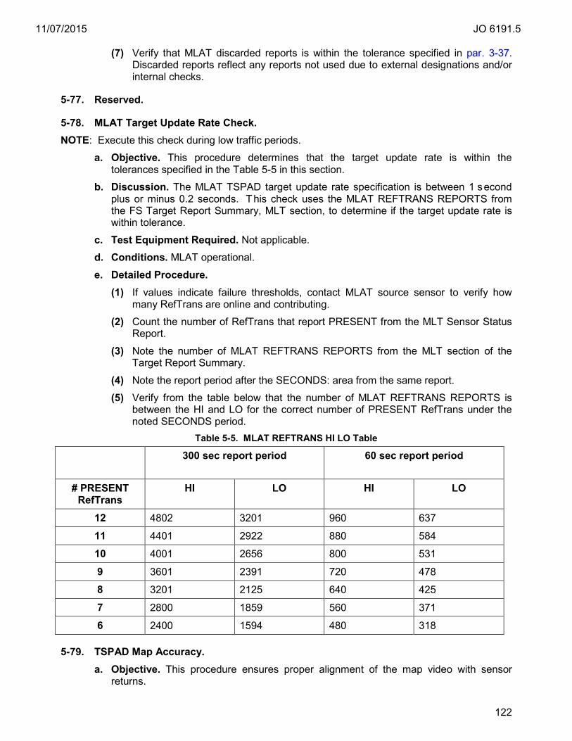
11/07/2015 JO 6191.5
122
(7) Verify that MLAT discarded reports is within the tolerance specified in par. 3-37. Discarded reports reflect any reports not used due to external designations and/or internal checks.
5-77. Reserved.
5-78. MLAT Target Update Rate Check. NOTE: Execute this check during low traffic periods.
a. Objective. This procedure determines that the target update rate is within the tolerances specified in the Table 5-5 in this section.
b. Discussion. The MLAT TSPAD target update rate specification is between 1 second plus or minus 0.2 seconds. This check uses the MLAT REFTRANS REPORTS from the FS Target Report Summary, MLT section, to determine if the target update rate is within tolerance.
c. Test Equipment Required. Not applicable. d. Conditions. MLAT operational. e. Detailed Procedure.
(1) If values indicate failure thresholds, contact MLAT source sensor to verify how many RefTrans are online and contributing.
(2) Count the number of RefTrans that report PRESENT from the MLT Sensor Status Report.
(3) Note the number of MLAT REFTRANS REPORTS from the MLT section of the Target Report Summary.
(4) Note the report period after the SECONDS: area from the same report.
(5) Verify from the table below that the number of MLAT REFTRANS REPORTS is between the HI and LO for the correct number of PRESENT RefTrans under the noted SECONDS period.
Table 5-5. MLAT REFTRANS HI LO Table
300 sec report period
60 sec report period
# PRESENT RefTrans
HI LO HI LO
12 4802 3201 960 637 11 4401 2922 880 584 10 4001 2656 800 531 9 3601 2391 720 478 8 3201 2125 640 425 7 2800 1859 560 371 6 2400 1594 480 318
5-79. TSPAD Map Accuracy. a. Objective. This procedure ensures proper alignment of the map video with sensor
returns.

11/07/2015 JO 6191.5
123
b. Discussion. This test shall verify correct map alignment with the sensor returns. The test may be c onducted with known fixes or targets of opportunity to verify runway centerline alignment and navigational aid alignment. There is a magnetic component to the FMA runways that should be eq ual to the magnetic declination of the primary sensor. Check with your OSF for details of the magnetic component of FMA runway configurations.
c. Test Equipment required. Not applicable.
d. Conditions. The FMA system is to be placed in an operational configuration.
e. Detailed Procedure. Use targets of opportunity or surveyed targets to verify map position. Check that arrivals are lining up on runway centerlines at primary airports. It is recommended to corroborate with AT for this check.
5-80. Reserved.
5-81. MLAT Fixed Target Map. a. Objective. Verify that Reference Transponders (RefTran) on the geographic map are
positioned correctly.
b. Discussion. The fixed target map is a set of MLAT RefTran and Reference Unit (RU) overlaying dots. These overlaying dots represent the location of transmittal and receiving equipment for the multi-lateration system. The RefTrans transmit a signal that is shown as a t arget on the display. Each site is responsible for having a N ational Automation Request (NAR) form submitted to the associated OSF so the OSF can update the site adaptation to reflect the location of the RefTrans and RUs. The NAR forms should provide the location of said test target locations. Requests to have the fixed target map generated should follow local policy.
c. Test Equipment Required. MLAT FMA fixed target maps are high definition, precision maps specified for 8x magnification and RefTran fixed target geo-marks made 24/512 nm by 2.5 ACP dimensions.
d. Conditions. Not applicable.
e. Detailed Procedures. (1) At a TCW, select FMA mode, select the multi-lateration sensor to check, and set
the display reference at the center of the display.
(2) Clear all maps from the TCW.
(3) Select the Fixed Target map that is associated to the sensor.
(4) Verify that all working RefTran symbols on the map are aligned and positioned with transmitted signals.
5-82. G4 Equipment LED Check. a. Objective. Perform an inspection on racked G4 equipment LEDs. b. Discussion. The STARS G4 equipment is comprised of various electronic components
that include LED indications for hardware, state and connection status. The MCW receives health messages from each hardware component. This check is verifies an LRU component status without communication or software dependencies.
c. Test Equipment Required. Not applicable. d. Conditions. These checks must be made while operational programs are being
executed. The checks are not comprehensive. They are limited to rack mounted

11/07/2015 JO 6191.5
124
equipment and to the “go” status of each inspected piece. GPS, A/B Gang Switch, are covered elsewhere in this handbook. TCW LED checks are excluded.
e. Detailed Procedure. Check LED indications on the following equipment list: (1) X2000 Processor ((FS/EFS) MCW, CGW, RDP, CDR).
(a) On the front of the processor, top middle above the hinged panel door key lock, there are six LEDs. The Power On should be illuminated blue; the HDD Activity may blink; the others should not be illuminated.
Figure 5-6. Front Panel X2000 Processor
(2) AT8000GS Gigabyte Switch (FS/EFS LAN Switch).
(a) The front of the switch, right side has four rows and three columns of Light Emitting Diodes (LED), the column labels on the top are PWR, SYS and MODE.
(b) The first two LEDs on the top row, under PWR and S YS should be steady green.
Figure 5-7. Right-Front AT8000GS Gigabyte Switch LEDs
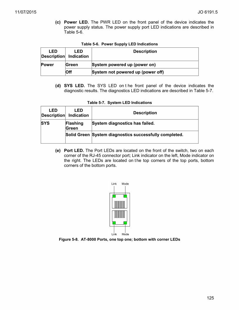
11/07/2015 JO 6191.5
125
(c) Power LED. The PWR LED on the front panel of the device indicates the power supply status. The power supply port LED indications are described in Table 5-6.
Table 5-6. Power Supply LED Indications
LED Description
LED Indication
Description
Power Green System powered up (power on) Off System not powered up (power off)
(d) SYS LED. The SYS LED on t he front panel of the device indicates the
diagnostic results. The diagnostics LED indications are described in Table 5-7.
Table 5-7. System LED Indications
(e) Port LED. The Port LEDs are located on the front of the switch, two on each corner of the RJ-45 connector port; Link indicator on the left, Mode indicator on the right. The LEDs are located on t he top corners of the top ports, bottom corners of the bottom ports.
Figure 5-8. AT-8000 Ports, one top one; bottom with corner LEDs
LED Description
LED Indication Description
SYS Flashing Green
System diagnostics has failed.
Solid Green System diagnostics successfully completed.
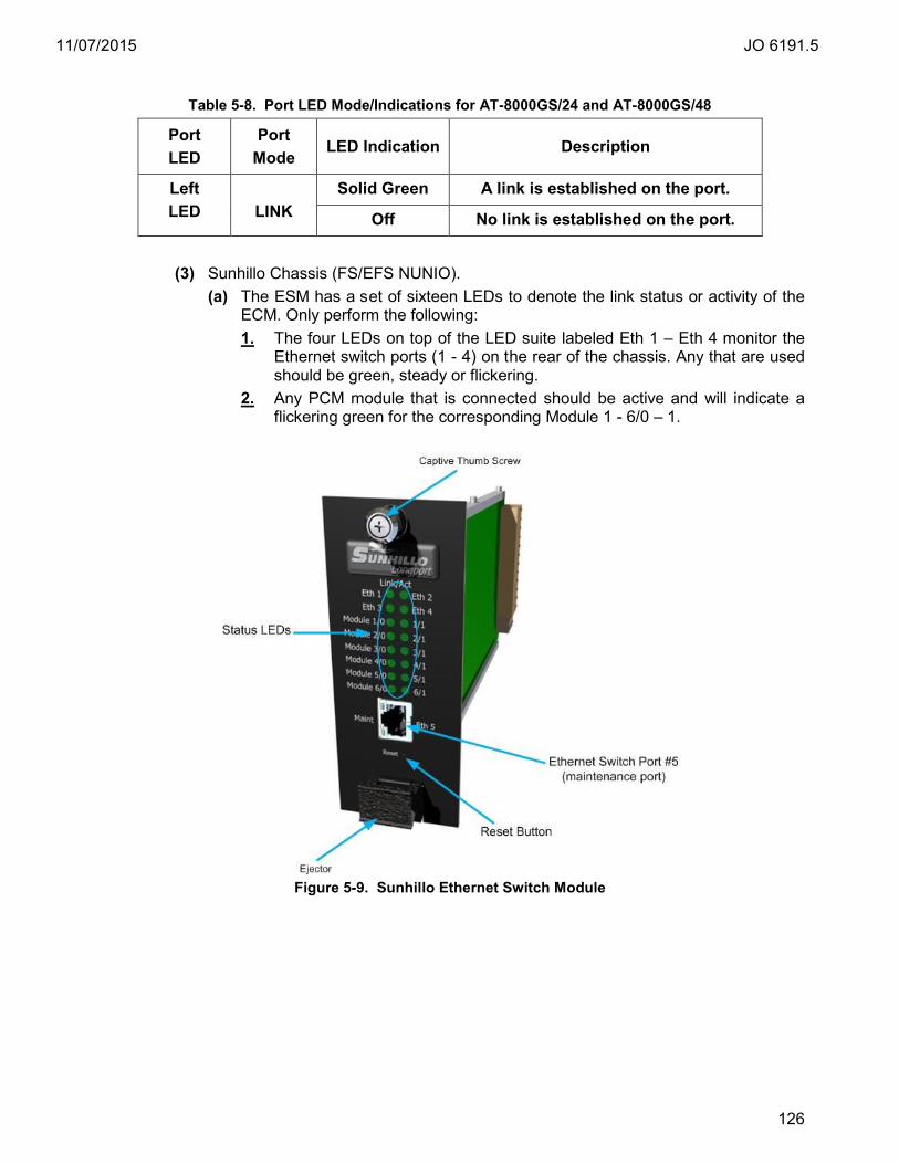
11/07/2015 JO 6191.5
126
Table 5-8. Port LED Mode/Indications for AT-8000GS/24 and AT-8000GS/48
Port LED
Port Mode
LED Indication Description
Left LED
LINK
Solid Green A link is established on the port.
Off No link is established on the port.
(3) Sunhillo Chassis (FS/EFS NUNIO). (a) The ESM has a set of sixteen LEDs to denote the link status or activity of the
ECM. Only perform the following: 1. The four LEDs on top of the LED suite labeled Eth 1 – Eth 4 monitor the
Ethernet switch ports (1 - 4) on the rear of the chassis. Any that are used should be green, steady or flickering.
2. Any PCM module that is connected should be active and will indicate a flickering green for the corresponding Module 1 - 6/0 – 1.
Figure 5-9. Sunhillo Ethernet Switch Module
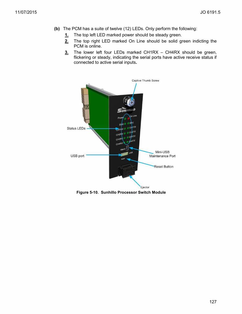
11/07/2015 JO 6191.5
127
(b) The PCM has a suite of twelve (12) LEDs. Only perform the following:
1. The top left LED marked power should be steady green. 2. The top right LED marked On Line should be solid green indicting the
PCM is online. 3. The lower left four LEDs marked CH1RX – CH4RX should be green,
flickering or steady, indicating the serial ports have active receive status if connected to active serial inputs.
Figure 5-10. Sunhillo Processor Switch Module
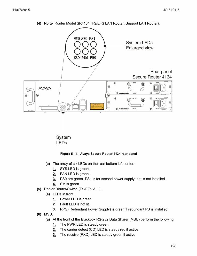
11/07/2015 JO 6191.5
128
(4) Nortel Router Model SR4134 (FS/EFS LAN Router, Support LAN Router).
Figure 5-11. Avaya Secure Router 4134 rear panel
(a) The array of six LEDs on the rear bottom left center. 1. SYS LED is green. 2. FAN LED is green. 3. PS0 are green. PS1 is for second power supply that is not installed. 4. SM is green.
(5) Rapier Router/Switch (FS/EFS AIG). (a) LEDs in front.
1. Power LED is green. 2. Fault LED is not lit. 3. RPS (Redundant Power Supply) is green if redundant PS is installed.
(6) MSU. (a) At the front of the Blackbox RS-232 Data Sharer (MSU) perform the following:
1. The PWR LED is steady green. 2. The carrier detect (CD) LED is steady red if active. 3. The receive (RXD) LED is steady green if active

11/07/2015 JO 6191.5
129
(7) Splitter.
(a) At the back of the Logical RS530 line splitters perform the following: 1. The DC LED should be steady green. 2. The C (clock), R (ready) and D (data) LEDs should be green; steady or
flickering. 3. There is an i ssue identified with the Logical line splitter power supply
where an internal capacitor degrades and the DC LED flickers so quickly that it cannot be detected by the human eye. Please reference par. 4-63 for periodic replacement guidance.
Figure 5-12. Logical RS530 Line Splitter Unit
(8) X2000 Processor (SSS, SIM, GPW) see (step 1).
5-83. No Print Report SAVE Procedure.
a. Objective. Provide a procedure for transferring saved electronic copies of reports from the system for longer term archive.
b. Discussion. Any numeric value that is used for a technical reference record data or technical performance records should be archived. STARS has reports with numeric values that are used as commissioning values, certification, performance checks and trend analysis. More recent STARS software versions (STARS S6.00R2 and later builds for STARS-TAMR sites or after STARS-TAMR software has merged with traditional STARS software) have the capability to save electronic copies of reports so it is not necessary to continue to print and k eep paper copies. The reports are stored on t he STARS system for a period of 31 days before deletion to prevent capacity issues. All stored electronic copies of reports must be accessible for specified time period in Order 6000.15 Therefore, the reports must periodically be t ransferred to a more permanent archive. More permanent archive resource, location and maintenance procedures (e.g., cleanup) are locally determined.
c. Test Equipment Required. Not applicable.
d. Conditions. Any STARS software version that has a SAVE button option on any MCW report has the option to store electronic copies of reports. The SAVE option is only available when DRDs are adapted. There are three directories that store reports located in /DRD#/SYS#/RCV/REPORTS/, where the first # is the DRD designation, the second # is the system level. The di rectories are MANUAL (all reports that are requested for display), PERIODIC (some reports can be adapted for automatic storage), and SAVED (reports stored when the SAVE option is selected). Only select SAVE for reports that are intended for archive per handbook(s) direction.
11/07/2015 JO 6191.5
130
e. Detailed Procedures. (1) The presence of a SAVE button option is an indication that the chosen report can
be saved electronically instead of printing. The specialist always has the option to print and save the report for convenience or necessity.
(2) At the MCW, if you have selected the desired report, check for a SAVE button at the bottom of the report as one of the selectable button options.
(3) When you have completed the procedure required using the displayed report or no longer need t o display the report, select the SAVE option. Note the pathname displayed on the bottom of the report. This is the location where the report data is stored. As examples:
/DRD1/SYS1/RCV/REPORTS/SAVED/<filename_report.rpt /DRD2/SYS1/RCV/REPORTS/SAVED/<filename_report.rpt /DRD1/SYS2/RCV/REPORTS/SAVED/<filename_report.rpt /DRD2/SYS2/RCV/REPORTS/SAVED/<filename_report.rpt
(4) The saved reports can be accessed from the SSS by logging in and navigating to the SAVED directories noted in the examples above.
(5) Saved reports are stored on the DRD for a period of 31 days.
5-84. Periodic Transfer of Saved Reports to Maintenance Laptop Procedure. a. Objective. Provide a procedure for archiving electronic copies of reports.
b. Discussion. STARS has reports that provide numeric values that are used as commissioning values, certification, performance checks and trend analysis. All stored electronic copies of reports must be archived for the specified time period in Order 6000.15. The reports are stored on the STARS system for a per iod of 31 days before deletion to prevent capacity issues. Therefore it is necessary to develop local procedures for longer term archive and subsequent cleanup of required reports.
c. Test Equipment Required. Not applicable.
d. Conditions. There are three directories to store reports located in /DRD#/SYS#/RCV/REPORTS/, where the first # is the DRD designation, the second # is the system level. The directories are MANUAL (all reports that are requested for display), PERIODIC (some reports can be adapt ed to be s tored automatically), and SAVED (reports stored when the SAVE option is selected). Only select SAVE for reports that are intended for archive per handbook direction.
e. Detailed Procedures. (1) If necessary to setup maintenance laptop, perform the TI6191.500 IETM “Configure
Maintenance Laptop for Connection to Site Support Hub/Router” procedure. It can be found with the IETM search string “Transferring Extracted CDR” then navigate forward to the Transfer Process Procedures page.
(2) Connect maintenance laptop to SSS as follows:
(a) Enable a port on support LAN router/switch (per TI 6191.500 for procedure if necessary).
(b) Using a straight-through CAT-5 (RJ45) cable, connect one end o f cable to Network Interface Card (NIC) port at back panel of maintenance laptop and other end of cable to an enabled port on STARS Site Support router.

11/07/2015 JO 6191.5
131
(c) Power up the maintenance laptop.
(d) Log in to the maintenance laptop.
(3) Log in to the SSS as a STARS user.
(4) Open an xterm window.
(5) In the xterm window, type cd /DRD#/SYS#/RCV/REPORTS/SAVED/ where first # is the DRD designation and second # is the SYS designation.
(6) Type ls –la and press <Enter> to display a list of all saved reports.
NOTE: In the step that follows, XXX.YYY.ZZZ.249 is a generic representation of the support LAN subnet IP address. T he maintenance laptop will take the 249 for the last octet (i.e., XXX.YYY.ZZZ.249 where XYZ are the subnet octets). Obtain the actual support LAN subnet IP address from the /etc/hosts file on the Site Support Server (SSS). The support LAN subnet IP address is listed under the information # STARS TAS Networks Configuration. I nstructions for printing /etc/hosts file are provided in Print Hosts File.
(7) Type ftp XXX.YYY.ZZZ.249.
(8) At Name (XXX.YYY.ZZZ.249:STARS username) prompt, type anonymous and press <Enter>. The following message is displayed: ... Anonymous access allowed, send identity (e-mail name) as password.
(9) At password prompt, press <Enter>. The following message is displayed: .... Anonymous user logged in
(10) At ftp> type bin and press <Enter>. The following message is displayed: Type Set to I.
(11) At ftp> type put [filename] and press <Enter> in which filename can use wildcard characters e.g., put *21MAY*.rpt for all saved reports for one day. Put *MAY*.rpt will get entire month if desired.
(12) At ftp> type bye and press <Enter>. SSS ftp session is terminated.
(13) This procedure places the transferred files into the data directory on t he laptop previously setup for ftp transfer. From this directory the reports may be burnt to a CD or moved to a thumb drive for transfer to the locally determined archive location.
5-85. Periodic Reboot of Avaya FSL/EFSL LAN B Routers. a. Objective. Provide a procedure for rebooting the FSL/EFSL LAN B routers connected
to radar towers to prevent an LRU failure caused by a firmware design oversight.
b. Discussion. Due to a des ign oversight, when the 32 bi t timer (in units of 10msec) wraps back to zero there is a l oss of communication. The timer wrap around to zero occurs in 497.1 days. The workaround is to reboot the routers on an annual basis.
c. Test Equipment Required Not applicable. d. Conditions. The procedure is for the FSL/EFSL LAN A routers. 48 to 72 hours later the
site should perform procedure par. 5-86 for rebooting the LAN B routers. This is done to keep the A and B router timers offset. This way, in the event of a missed task, it reduces the occurrence of a total operational failure.
e. Detailed Procedures. (1) Both LANS on a service level must status PASS.
(2) At rear of the FSL LAN B router, set the power switch to off (0).
(3) At rear of the FSL LAN B router, set the power switch to on (1).
11/07/2015 JO 6191.5
132
(4) Repeat this procedure for EFSL LAN B router.
(5) Check MCW or Green/PASS icons.
5-86. Periodic Reboot of Avaya FSL/EFSL LAN A Routers. a. Objective. Provide a procedure for rebooting the FSL/EFSL LAN A routers connected
to radar towers to prevent an LRU failure caused by a firmware design oversight.
b. Discussion. Due to a des ign oversight, when the 32 bi t timer (in units of 10msec) wraps back to zero there is a l oss of communication. The timer wrap around to zero occurs in 497.1 days. The workaround is to reboot the routers on an annual basis.
c. Test Equipment Required. Not applicable.
d. Conditions. Perform this procedure 48 to 72 hours after performing par. 5-85.
e. Detailed Procedures. (1) Both LANS on each service level (FSL/SYS1 and EFSL/SYS2) must status PASS.
(2) At rear of the FSL LAN A router, set the power switch to off (0).
(3) At rear of the FSL LAN A router, set the power switch to on (1).
(4) Repeat this procedure for EFSL LAN A router.
(5) Check MCW or Green/PASS icons.
5-87. – 5-99. Reserved.
11/07/2015 JO 6191.5
133
Chapter 6. Flight Inspection
6-1. General. a. Flight inspections are made to verify the overall performance of radar, navigation aids,
and air/ground communications systems. Direction for flight inspections are contained in the latest edition of Order 8200.1, United States Standard Flight Inspection Manual.
b. Direction for flight inspections following an aircraft accident are contained in the latest edition of Order 8020.16, Air Traffic Organization Aircraft Accident and Incident Notification, Investigation, and Reporting.
6-2. – 6-99. Reserved.

11/07/2015 JO 6191.5
134
Appendix A. Certification Requirements
1. General. This appendix contains certification requirements for surveillance services provided in the terminal ATC environment, and certification requirements for constituent systems used to provide these services. Refer to Order 6000.15 for general guidance on the certification of services and systems.
2. Services. A service is defined as a system or group of systems providing some functional benefit to a user. The terminal surveillance service provides a m eans for ATC personnel to determine aircraft position and course during aircraft operations. These services are certified as Terminal Automated Radar Service, (TARS), and Radar Tower Automation Display Service (RTADS) in accordance with tables included in this appendix.
a. TARS is a mutually dependent surveillance and automation display service, relying on a combination of ATC and ai rborne systems. TARS relies on surveillance data from short-range sensors, long-range sensors, or combinations of sensors to provide ATC personnel with a means to determine aircraft position and course. TARS enhances surveillance capabilities by displaying real-time aircraft transponder data, e.g., pressure altitude, indicated airspeed, squawk codes, and by linking real-time flight data with flight plan data, and aut omating the handling of surveillance tracking to appropriate ATC sectors.
b. RTADS provides terminal surveillance radar data processing from the automation system to display targets and alphanumeric data on the display(s) at a remote tower.
c. ADSS provides a surveillance service that enables equipped aircraft, or surface vehicles, to periodically broadcast their identification, position, altitude, velocity, and other information. ADS-B utilizes equipment on the aircraft for providing positional information to air traffic specialists. ADS-B is automatic because no external stimulus is required for the aircraft to periodically broadcast its messages; it is dependent because it relies on on-board navigation equipment to provide the aircraft state vector.
3. Systems. Centralized, distributed, or backup surveillance processing systems, TCW or TDW are used to provide these services. The system is certified STARS in accordance with this appendix.
a. Certification of systems and subsystems is now event based. Event based certification removes the periodic requirement for certification, and requires certification whenever maintenance or administrative activities affecting system or subsystem operations occur. Refer to Order 6000.15, General Maintenance Handbook for NAS Facilities, for specific guidance on event based certification.
b. For facilities that have remote towers with direct radar feeds, it is necessary to have the assistance of personnel at the remote tower to conduct certification activities. It is necessary to have proper coordination between the certifying official at the TRACON or RAPCON and the remote tower. In these cases local and/or regional procedures should be developed, if necessary, in order to facilitate activities between distant facilities and convey certification information.
11/07/2015 JO 6191.5
135
Appendix A. Certification Requirements
4. Exceptions. Order 6000.15 permits certification with exceptions where a s ystem provides somewhat less than its full functional benefit but is still useable, e.g., one level (EFSL) is taken out of service, yet another level (FSL) is contributing to the terminal surveillance service. Outstanding exceptions may be certified in accordance with the tables included in this appendix. Additional guidance is given for the specific purpose of removing the exceptions.
5. Transition Phase. As surveillance processing systems are replaced, it is necessary to run dual processing operations. To accommodate different configurations that are subject to change, the reference paragraphs in this appendix are provided in separate columns for each of the applicable configurations. All procedures for each configuration currently in operation shall be accomplished.
6. Future Systems. For future planning purposes, systems that provide the above services or are used for testing or prototyping shall be c ertified in accordance with Order 6000.15, General Maintenance Handbook for NAS Facilities.
7. Certification Techniques. General certification techniques are defined in Order 6000.15, par. 505. User report of satisfactory operation is included as one o f the techniques and may be us ed to support certification judgments at remote facilities.

11/07/2015 JO 6191.5
136
Appendix A. Certification Requirements: Part 1. Overall Service Table A-1. Terminal Automated Radar Service (TARS)
Advertised Service
Certification Parameter Reference Paragraph
TARS Knowledge that the constituent surveillance systems are certified or suitable for NAS.
FAA sites should log onto the Remote Monitoring and Logging System (RMLS) or use any means available to determine if constituent Surveillance Radar System, Surveillance Interrogator System, and Surveillance Flight Planning System is certified. Sites can reference FAAO 6000.6 for an explanation of DoD certification guidelines and responsibilities.
STARS and Terminal Automated Display System (TADS) are certified.
Appendix A, Table A-2, A-4.
TARS Automation Capability. Normal indications of alphanumeric data on display. Data updates and displays as expected.
Visual observation and user collaboration. At minimum one display, verify single sensor display, fusion display and/or multi-mode display, whichever are applicable.
Surveillance Data Accuracy and Integrity. PARROT/PE Report Check.
par. 3-3; par. 5-12
TARS Sensor Registration. (Fused and Non-Fused modes have different tolerances. Site only required to perform registration that matches their registration operating mode) Calc Mode Auto Mode None Mode
par. 3-6; Check registration icons. par. 3-6: Check registration icons. par. 3-6; 5-17
Inter-Facility Data Transfer (IFDT) on active system. par. 3-15; par. 5-28
Normal Certification Interval: Daily. Allowable Exception Examples: Associated surveillance source ID, IFDT. Person Responsible for Certification: ATSS with certification authority. Certification Entries in the TARS Maintenance Log:
Without Exception: TARS certified.
With Exception Example: TARS certified except [location identifier] [associated surveillance system]. TARS certified except IFDT.
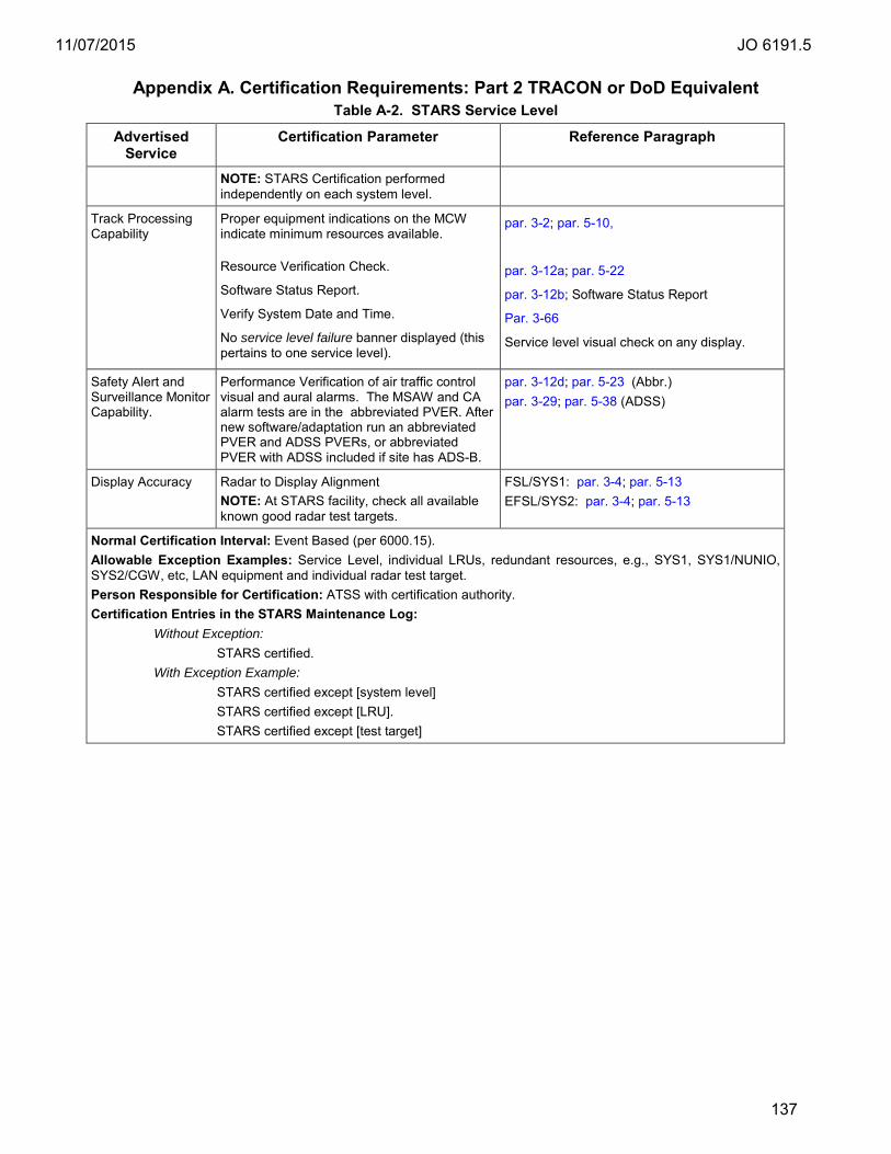
11/07/2015 JO 6191.5
137
Appendix A. Certification Requirements: Part 2 TRACON or DoD Equivalent Table A-2. STARS Service Level
Advertised Service
Certification Parameter Reference Paragraph
NOTE: STARS Certification performed independently on each system level.
Track Processing Capability
Proper equipment indications on the MCW indicate minimum resources available.
Resource Verification Check.
Software Status Report.
Verify System Date and Time.
No service level failure banner displayed (this pertains to one service level).
par. 3-2; par. 5-10,
par. 3-12a; par. 5-22
par. 3-12b; Software Status Report
Par. 3-66
Service level visual check on any display.
Safety Alert and Surveillance Monitor Capability.
Performance Verification of air traffic control visual and aural alarms. The MSAW and CA alarm tests are in the abbreviated PVER. After new software/adaptation run an abbreviated PVER and ADSS PVERs, or abbreviated PVER with ADSS included if site has ADS-B.
par. 3-12d; par. 5-23 (Abbr.) par. 3-29; par. 5-38 (ADSS)
Display Accuracy Radar to Display Alignment NOTE: At STARS facility, check all available known good radar test targets.
FSL/SYS1: par. 3-4; par. 5-13 EFSL/SYS2: par. 3-4; par. 5-13
Normal Certification Interval: Event Based (per 6000.15). Allowable Exception Examples: Service Level, individual LRUs, redundant resources, e.g., SYS1, SYS1/NUNIO, SYS2/CGW, etc, LAN equipment and individual radar test target. Person Responsible for Certification: ATSS with certification authority. Certification Entries in the STARS Maintenance Log:
Without Exception: STARS certified.
With Exception Example: STARS certified except [system level] STARS certified except [LRU]. STARS certified except [test target]

11/07/2015 JO 6191.5
138
Appendix A. Certification Requirements: Part 2 TRACON or DOD Equivalent Table A-3. Automatic Dependent Surveillance Service (ADSS)
Advertised Service Certification Parameter Reference Paragraph Safety Processing Capability Target Presentation Capability
Knowledge that the constituent STARS and TADS system, and TARS service, are certified.
Appendix A, Table A-2, A-4 and A-1
Surveillance Volume Availability. Indications that minimum required ADSS service volume is available.
par. 3-27a. – c.; par. 5-35e(1) – (3)
ADSS Reported Test Target Accuracy. par. 3-27d.; par. 5-35e(4)
ADSS Test Target Display Accuracy. par. 3-27e.; par.5-35e(5)
Normal Certification Interval: Daily. Allowable Exception Examples: designated display(s), ground station Person Responsible for Certification: ATSS with certification authority. Certification Entries in the ADSS Maintenance Log:
Without Exception: ADSS certified.
With Exception Example: ADSS certified except [ground station]. ADSS certified except target presentation capability.

11/07/2015 JO 6191.5
139
Appendix A. Certification Requirements: Part 2 TRACON or DOD Equivalent Table A-4. TRACON Automation Display System (TADS)
Advertised Service Certification Parameter (only those applicable)
Reference Paragraph
Display Capability Service Level Availability Aural Alarm Capability
Knowledge that the constituent STARS is certified. No workstation failure or failure indications displayed in SSA or lack of user complaint. Display focus, color and alignment.
Appendix A, Table A-2. FSL/SYS1: Check SSA. EFSL/SY2: Check SSA. Visual satisfaction and/or lack of user complaint.
FSL system status alert color check. EFSL system status alert color check.
FSL/SYS1: par. 3-16; par. 5-27 EFSL/SYS2: : par. 3-16; par. 5-27
FS/EFS Availability Status Check. FSL/SYS1: par. 3-14; par. 5-25 EFSL/SYS2: par. 3-14; par. 5-25
Aural alarm check. FSL/SYS1: par. 3-67: TI6191.409 Audible Alarm Test or adjust Volume on DCB. EFSL/SYS2: par. 3-67: TI6191.409 Audible Alarm Test or adjust Volume on DCB.
NOTE: TADS does not apply to RPO positions. TMU positions are certified for data entry and traffic management functions; not for vector or separation.
Normal Certification Interval: Event based. Allowable Exception Examples: Designated display(s). Person Responsible for Certification: ATSS with certification authority. Certification Entries in the TADS Maintenance Log:
Without Exception: TADS certified. TADS [designated display] certified. TADS [designated display] [service level] certified.
With Exception Example: TADS certified except [designated display]. TADS certified except [designated display] [service level].
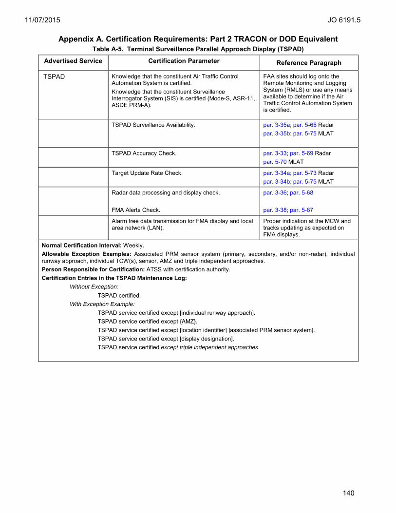
11/07/2015 JO 6191.5
140
Appendix A. Certification Requirements: Part 2 TRACON or DOD Equivalent Table A-5. Terminal Surveillance Parallel Approach Display (TSPAD)
Advertised Service Certification Parameter Reference Paragraph
TSPAD Knowledge that the constituent Air Traffic Control Automation System is certified. Knowledge that the constituent Surveillance Interrogator System (SIS) is certified (Mode-S, ASR-11, ASDE PRM-A).
FAA sites should log onto the Remote Monitoring and Logging System (RMLS) or use any means available to determine if the Air Traffic Control Automation System is certified.
TSPAD Surveillance Availability.
par. 3-35a; par. 5-65 Radar par. 3-35b: par. 5-75 MLAT
TSPAD Accuracy Check. par. 3-33; par. 5-69 Radar par. 5-70 MLAT
Target Update Rate Check. par. 3-34a; par. 5-73 Radar par. 3-34b; par. 5-75 MLAT
Radar data processing and display check. FMA Alerts Check.
par. 3-36; par. 5-68 par. 3-38; par. 5-67
Alarm free data transmission for FMA display and local area network (LAN).
Proper indication at the MCW and tracks updating as expected on FMA displays.
Normal Certification Interval: Weekly. Allowable Exception Examples: Associated PRM sensor system (primary, secondary, and/or non-radar), individual runway approach, individual TCW(s), sensor, AMZ and triple independent approaches. Person Responsible for Certification: ATSS with certification authority. Certification Entries in the TSPAD Maintenance Log:
Without Exception: TSPAD certified.
With Exception Example: TSPAD service certified except [individual runway approach]. TSPAD service certified except {AMZ}. TSPAD service certified except [location identifier] ]associated PRM sensor system]. TSPAD service certified except [display designation]. TSPAD service certified except triple independent approaches.

11/07/2015 JO 6191.5
141
Appendix A. Certification Requirements: Part 3 Radar Tower Table A-6. Radar Tower Automation Display Service (RTADS)
Advertised Service
Certification Parameter Reference Paragraph
RTADS Knowledge that the constituent RTDS system, TARS and ADSS (if applicable) services are certified.
Sensor Availability. Any applicable sensor, including the ADSS sensor, not indicated as failed in SSA.
Data Entry and Display capability. Proper data entry processing and display functions at display positions. NOTE: Check fusion, current primary single sensor and/or multi-mode; any that are applicable.
FSL/SYS1: par. 3-72a; EFSL/SYS2: par. 3-72b
Tower Radar to Display Alignment. NOTE: At RTDS facility, check one available test target.
FSL/SYS1: par. 3-24; par. 5-31 EFSL/SYS2: par. 3-24; par. 5-31
ADSS Test Target Display Accuracy. NOTE: Check only one ADS-B fixed beacon target.
FSL/SYS1: par. 3-25.; par. 5-39 FSL/SYS2: par. 3-25.; par. 5-39
Normal Certification Interval: Weekly. Allowable Exception Examples: Associated surveillance system ID. Person Responsible for Certification: ATSS with certification authority. Certification Entries in the RTADS Maintenance Log:
Without Exception: RTADS certified.
With Exception Example: RTADS certified except [location identifier] surveillance system.

11/07/2015 JO 6191.5
142
Appendix A. Certification Requirements: Part 3 Radar Tower Table A-7. Radar Tower Display System (RTDS)
Advertised Service
Certification Parameter
Reference Paragraph
Radar Tower Display Capability.
No workstation failure or failure indications displayed in SSA.
FSL/SYS1: Check SSA. EFSL/SY2: Check SSA.
Monitor Capability Alert Color Display Capability
Display focus, color and alignment. FSL system status alert color check. EFSL system status alert color check.
Visual satisfaction and/or lack of user complaint. FSL: par. 3-16; par. 5-27 EFSL: par. 3-16; par. 5-27
Service Level Availability
FS/EFS Availability Status Check. FSL/SYS1: par. 3-14; par. 5-25 EFSL/SYS2: par. 3-14; par. 5-25
Aural Alarm Capability
Aural alarm check.
FSL: par. 3-67: TI6191.409 Audible Alarm Test. EFSL: par. 3-67: TI6191.409 Audible Alarm Test.
NOTE: RTDS does not apply to SDM(s).
Normal Certification Interval: Event Based (per Order 6000.15). Allowable Exception Examples: Individual TDW(s). Person Responsible for Certification: ATSS at the ATCT with certification authority. Certification Entries in the RTDS Maintenance Log:
Without Exception: RTDS certified.
With Exception Example: RTDS certified except [designated display]. RTDS certified except [system level].
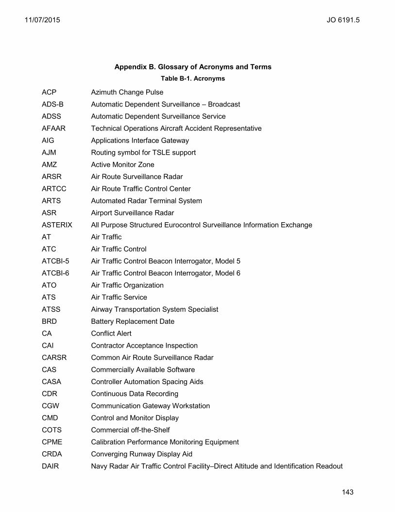
11/07/2015 JO 6191.5
143
Table B- 1. Acronyms
Appendix B. Glossary of Acronyms and Terms Table B-1. Acronyms
ACP Azimuth Change Pulse
ADS-B Automatic Dependent Surveillance – Broadcast
ADSS Automatic Dependent Surveillance Service
AFAAR Technical Operations Aircraft Accident Representative
AIG Applications Interface Gateway
AJM Routing symbol for TSLE support
AMZ Active Monitor Zone
ARSR Air Route Surveillance Radar
ARTCC Air Route Traffic Control Center
ARTS Automated Radar Terminal System
ASR Airport Surveillance Radar
ASTERIX All Purpose Structured Eurocontrol Surveillance Information Exchange
AT Air Traffic
ATC Air Traffic Control
ATCBI-5 Air Traffic Control Beacon Interrogator, Model 5
ATCBI-6 Air Traffic Control Beacon Interrogator, Model 6
ATO Air Traffic Organization
ATS Air Traffic Service
ATSS Airway Transportation System Specialist
BRD Battery Replacement Date
CA Conflict Alert
CAI Contractor Acceptance Inspection
CARSR Common Air Route Surveillance Radar
CAS Commercially Available Software
CASA Controller Automation Spacing Aids
CDR Continuous Data Recording
CGW Communication Gateway Workstation
CMD Control and Monitor Display
COTS Commercial off-the-Shelf
CPME Calibration Performance Monitoring Equipment
CRDA Converging Runway Display Aid
DAIR Navy Radar Air Traffic Control Facility–Direct Altitude and Identification Readout

11/07/2015 JO 6191.5
144
Appendix B. Glossary of Acronyms and Terms Table B-1. Acronyms
DASI Digital Altimeter Setting Indicator
DAT Digital Audio Tape
DBRITE Digital Bright Radar Indicator Tower Equipment
DCB Display Control Bar
DCP Display Control Panel
DLT Digital Linear Tape
DoD Department of Defense
DRF Direct Radar Feed, also Data Recording Facility
DSF Direct Sensor Feed
EDC Early Display Configuration
EARTS En route Automated Radar Terminal System
EAS Existing ARTS System
ES Emergency Service
EFSL Emergency Service Level
ETMS Enhanced Traffic Management System
FAA Federal Aviation Administration
FCON Full Consolidation
FDB Full Data Block
FMA Final Monitor Aid
FRD Facility Reference Data
FS–1 Full STARS phase 1
FS–2 Full STARS phase 2
FSL Full Service Level
G4 Generation 4
GPS Global Positioning System
GPW General Purpose Workstation HEPA High Efficiency Particulate Air
ID IDAT
Identification Inter-Facility Data
IEEE Institute of Electrical & Electronic Engineers
IFDT Inter-Facility Data Transfer
IOC Initial Operational Capability
IP Internet Protocol
IETM Interactive Electronic Technical Manual
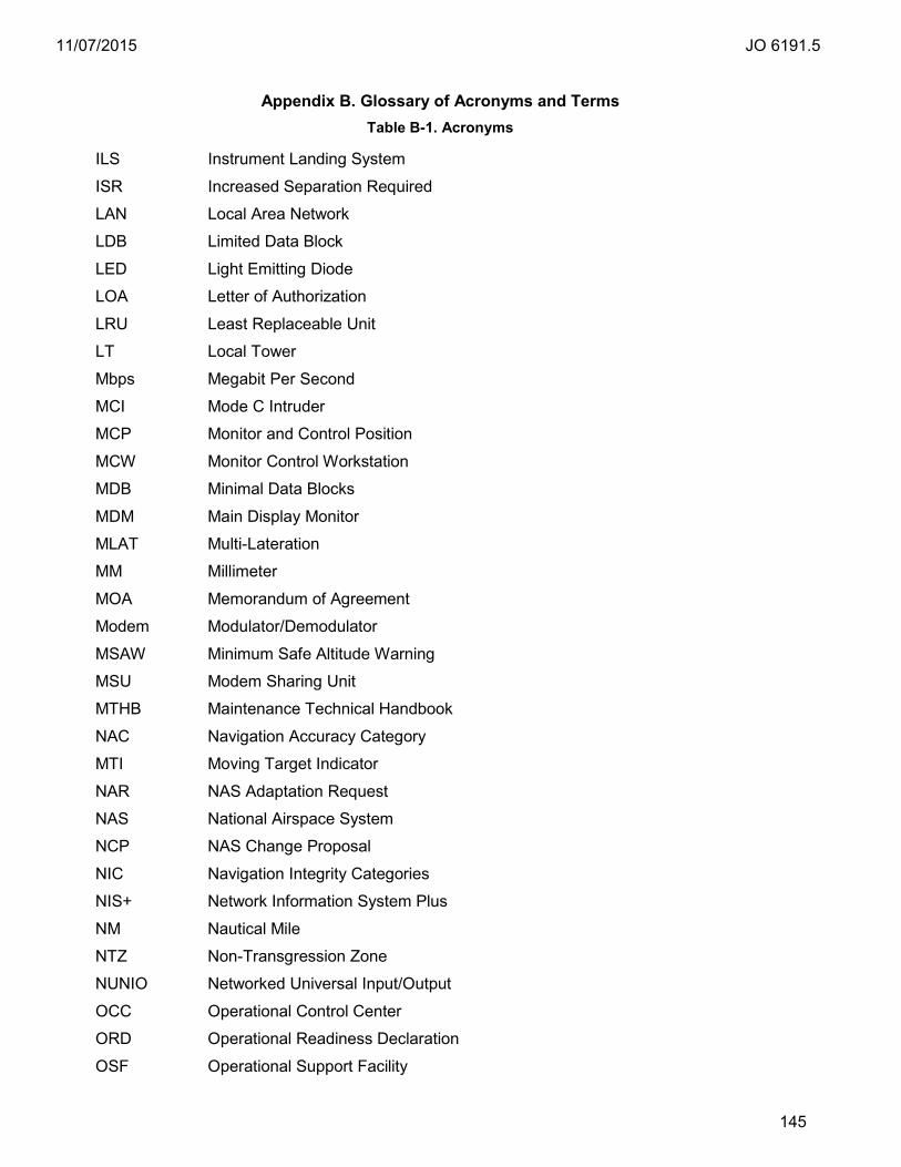
11/07/2015 JO 6191.5
145
Appendix B. Glossary of Acronyms and Terms Table B-1. Acronyms
ILS Instrument Landing System
ISR Increased Separation Required
LAN Local Area Network
LDB Limited Data Block
LED Light Emitting Diode
LOA Letter of Authorization
LRU Least Replaceable Unit
LT Local Tower
Mbps Megabit Per Second
MCI Mode C Intruder
MCP Monitor and Control Position
MCW Monitor Control Workstation
MDB Minimal Data Blocks
MDM Main Display Monitor
MLAT Multi-Lateration
MM Millimeter
MOA Memorandum of Agreement
Modem Modulator/Demodulator
MSAW Minimum Safe Altitude Warning
MSU Modem Sharing Unit
MTHB Maintenance Technical Handbook
NAC Navigation Accuracy Category
MTI Moving Target Indicator
NAR NAS Adaptation Request
NAS National Airspace System
NCP NAS Change Proposal
NIC Navigation Integrity Categories
NIS+ Network Information System Plus
NM Nautical Mile
NTZ Non-Transgression Zone
NUNIO Networked Universal Input/Output
OCC Operational Control Center
ORD Operational Readiness Declaration
OSF Operational Support Facility

11/07/2015 JO 6191.5
146
Appendix B. Glossary of Acronyms and Terms Table B-1. Acronyms
PAM Parallel Approach Monitor
PARROT Position Adjustable Range Reference Orientation Transponder
PC Personal Computer
PE Permanent Echo
PIDP Programmable Indicator Display Processor
PPS Present Position Symbol
PRM Precision Runway Monitor
PRM-A Precision Runway Monitor – Alternate
PSR Primary Surveillance Radar
PTL Predicted Time Line
PTR Program Technical Report
PVER Performance Verification
R&R Remove and Replace
RAID Redundant Array Of Independent Disks
RAPCON Radar Approach Control
RATCF Radar Air Traffic Control Facility
RDP Radar Data Processor
RT Radar Tower
RTADS Radar Tower Automation Display Service
RTDS Radar Tower Display System
RTQC RealTime Quality Control
SCAP System Certification and Accreditation Package
SDM Supplemental Display Monitor
SIL Surveillance Integrity Level
SCSC STARS Central Support Complex
SIMSYS Simulator Processor
SMO System Management Office
SMS Safety Management System
SOS STARS Operational Site
SPC Special Code
SR Search Radar
SRM Safety Risk Management
SRMD Safety Risk Management Document
SSA System Status Area
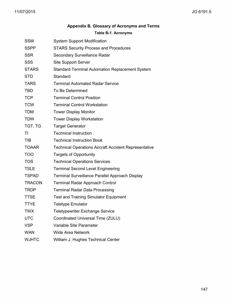
11/07/2015 JO 6191.5
147
Appendix B. Glossary of Acronyms and Terms Table B-1. Acronyms
SSM System Support Modification
SSPP STARS Security Process and Procedures
SSR Secondary Surveillance Radar
SSS Site Support Server
STARS Standard Terminal Automation Replacement System
STD Standard
TARS Terminal Automated Radar Service
TBD To Be Determined
TCP Terminal Control Position
TCW Terminal Control Workstation
TDM Tower Display Monitor
TDW Tower Display Workstation
TGT, TG Target Generator
TI Technical Instruction
TIB Technical Instruction Book
TOAAR Technical Operations Aircraft Accident Representative
TOO Targets of Opportunity
TOS Technical Operations Services
TSLE Terminal Second Level Engineering
TSPAD Terminal Surveillance Parallel Approach Display
TRACON Terminal Radar Approach Control
TRDP Terminal Radar Data Processing
TTSE Test and Training Simulator Equipment
TTYE Teletype Emulator
TWX Teletypewriter Exchange Service
UTC Coordinated Universal Time (ZULU)
VSP Variable Site Parameter
WAN Wide Area Network
WJHTC William J. Hughes Technical Center
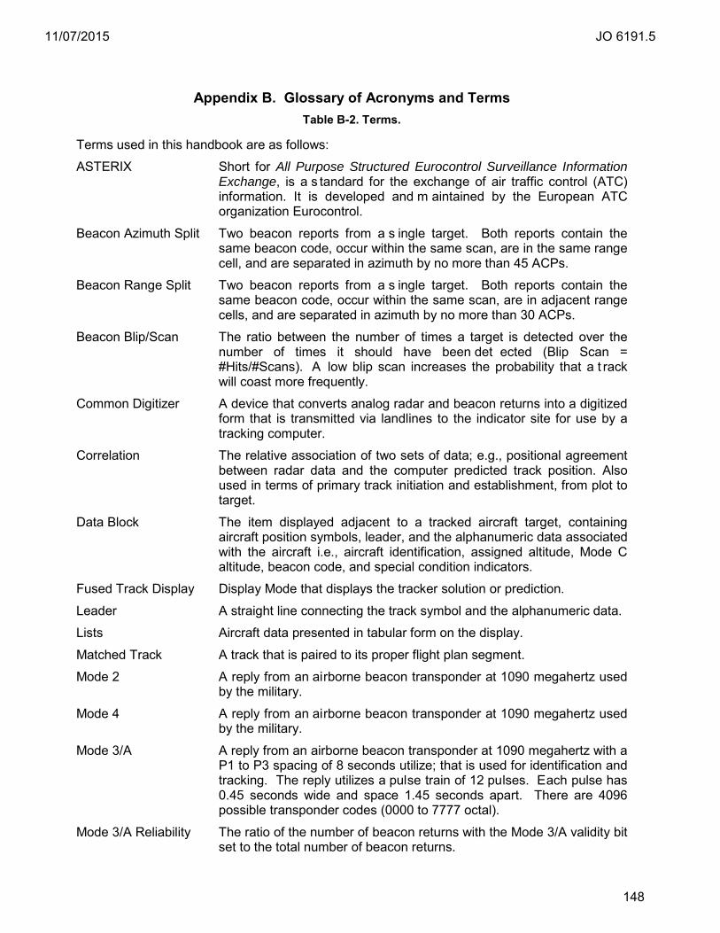
11/07/2015 JO 6191.5
148
Table B- 2. Terms
Appendix B. Glossary of Acronyms and Terms Table B-2. Terms.
Terms used in this handbook are as follows:
ASTERIX Short for All Purpose Structured Eurocontrol Surveillance Information Exchange, is a s tandard for the exchange of air traffic control (ATC) information. It is developed and m aintained by the European ATC organization Eurocontrol.
Beacon Azimuth Split Two beacon reports from a s ingle target. Both reports contain the same beacon code, occur within the same scan, are in the same range cell, and are separated in azimuth by no more than 45 ACPs.
Beacon Range Split Two beacon reports from a s ingle target. Both reports contain the same beacon code, occur within the same scan, are in adjacent range cells, and are separated in azimuth by no more than 30 ACPs.
Beacon Blip/Scan The ratio between the number of times a target is detected over the number of times it should have been det ected (Blip Scan = #Hits/#Scans). A low blip scan increases the probability that a t rack will coast more frequently.
Common Digitizer A device that converts analog radar and beacon returns into a digitized form that is transmitted via landlines to the indicator site for use by a tracking computer.
Correlation The relative association of two sets of data; e.g., positional agreement between radar data and the computer predicted track position. Also used in terms of primary track initiation and establishment, from plot to target.
Data Block The item displayed adjacent to a tracked aircraft target, containing aircraft position symbols, leader, and the alphanumeric data associated with the aircraft i.e., aircraft identification, assigned altitude, Mode C altitude, beacon code, and special condition indicators.
Fused Track Display Display Mode that displays the tracker solution or prediction.
Leader A straight line connecting the track symbol and the alphanumeric data.
Lists Aircraft data presented in tabular form on the display.
Matched Track A track that is paired to its proper flight plan segment.
Mode 2 A reply from an airborne beacon transponder at 1090 megahertz used by the military.
Mode 4 A reply from an airborne beacon transponder at 1090 megahertz used by the military.
Mode 3/A A reply from an airborne beacon transponder at 1090 megahertz with a P1 to P3 spacing of 8 seconds utilize; that is used for identification and tracking. The reply utilizes a pulse train of 12 pulses. Each pulse has 0.45 seconds wide and space 1.45 seconds apart. There are 4096 possible transponder codes (0000 to 7777 octal).
Mode 3/A Reliability The ratio of the number of beacon returns with the Mode 3/A validity bit set to the total number of beacon returns.

11/07/2015 JO 6191.5
149
Appendix B. Glossary of Acronyms and Terms Table B-2. Terms.
Mode 3/A Validity The mode 3/A validity bit is set by the digitizer when two successive replies in a r esponse from the same aircraft are identical. If two successive code matches are not found before target trail edge then the validation bit is set to zero.
Mode C A reply from an airborne beacon transponder at 1090 megahertz with a P1 to P3 spacing of 21 microseconds utilize to automatically report uncorrected pressure altitude to the nearest 100 feet.
Mode C Reliability The ratio of the number of beacon returns with the Mode C validity bit set to the total number of beacon returns.
Mode C Validity The mode C validity bit is set by the digitizer when two successive replies in a r esponse from the same aircraft are identical. If two successive code matches are not found before target trail edge then the validation bit is set to zero.
National Airspace System
The common system of facilities, equipment, regulations, procedures, and personnel required for the safe and efficient movement of civil and military aircraft through the airspace of the United States.
Navigation Accuracy Categories Position
The Navigation Accuracy Category for Position (NACP) is reported so that surveillance applications may determine whether the reported position has an ac ceptable level of accuracy for the intended use. It is a 95% accuracy bound on position.
Navigation Integrity Categories
The Navigation Integrity Category (NIC) is reported so that surveillance applications may determine whether the reported position has an acceptable level of integrity for the intended use. The value of the NIC parameter specifies an integrity containment radius, RC.
Preferred Coverage The radar-designated preferential coverage over a particular geographical area where coverage is available from two or more radars.
Radar Reinforced Rate
A ratio of the number of times a beacon target was detected in the same range cell as a search target with overlapping azimuths over the total number beacon targets (total = reinforced + beacon only) (RR Rate = #RR/(#RR + #BO)).
Search Range Split A search report detected in an adj acent range cell as a r einforced beacon target that has an azimuth separation of no m ore than one digitizer sliding window size. A search split also occurs when a beacon only target is detected and two search reports are detected in adjacent range cells and t he azimuth separation is no m ore than one digitizer sliding window size.
Surveillance Integrity Level
The value of the SIL parameter specifies the probability of the true position lying outside the NIC-specified containment radius, RC, without alerting, including the effects of the airborne equipment condition, which airborne equipment is in use, and w hich external signals are used. SIL is a s tatic (unchanging) value that depends on the position sensor being used on the aircraft.
Sort Box An area around a r adar return used to eliminate from correlation

11/07/2015 JO 6191.5
150
Appendix B. Glossary of Acronyms and Terms Table B-2. Terms.
consideration all tracks whose positions are outside the sort box limits.
Supplemental Coverage
Radar having overlapping coverage over a particular area, but not classified as preferred coverage.
Target History A display of stored past and present positions of an aircraft target.
Tracking Positional agreement of a r adar target and the computer predicted position. Computation of the difference between the predicted position and the actual position of the target.
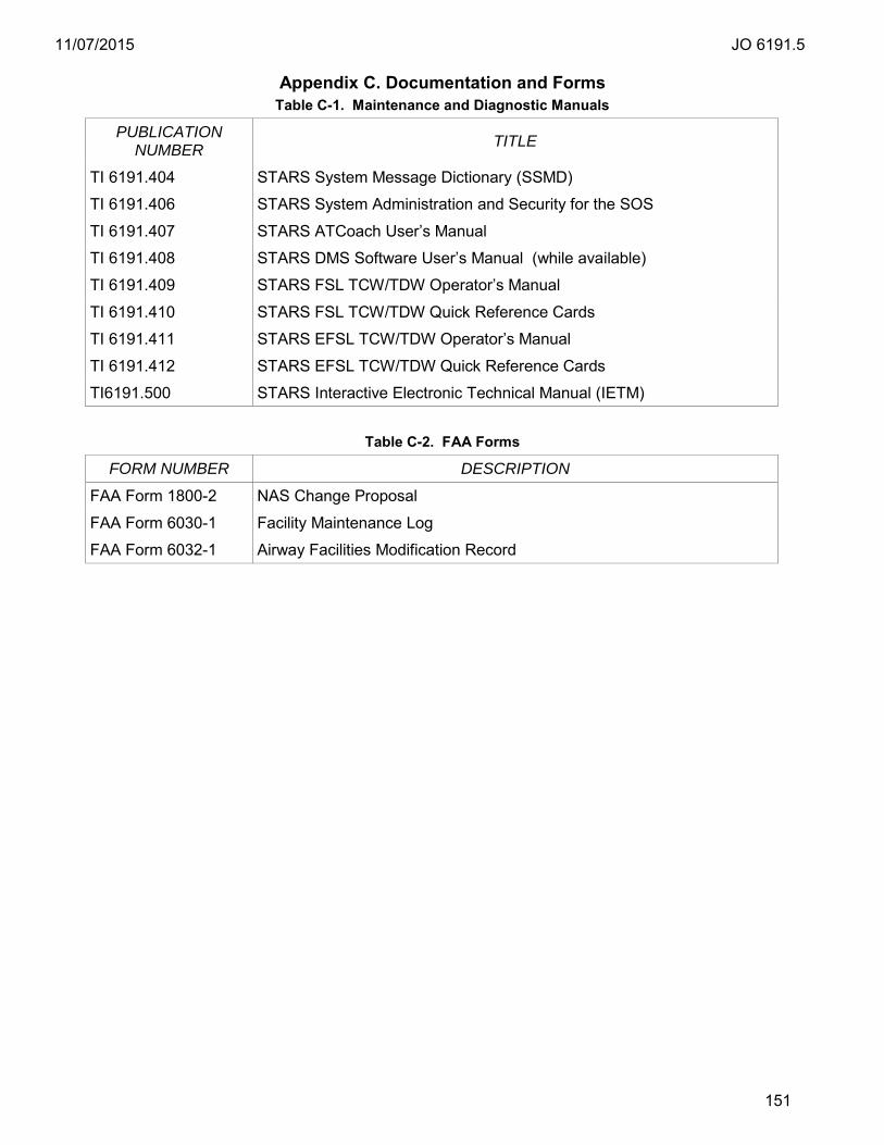
11/07/2015 JO 6191.5
151
Appendix C. Documentation and Forms Table C-1. Maintenance and Diagnostic Manuals
PUBLICATION NUMBER TITLE
TI 6191.404 STARS System Message Dictionary (SSMD)
TI 6191.406 STARS System Administration and Security for the SOS
TI 6191.407 STARS ATCoach User’s Manual
TI 6191.408 STARS DMS Software User’s Manual (while available)
TI 6191.409 STARS FSL TCW/TDW Operator’s Manual
TI 6191.410 STARS FSL TCW/TDW Quick Reference Cards
TI 6191.411 STARS EFSL TCW/TDW Operator’s Manual
TI 6191.412 STARS EFSL TCW/TDW Quick Reference Cards
TI6191.500 STARS Interactive Electronic Technical Manual (IETM)
Table C-2. FAA Forms
FORM NUMBER DESCRIPTION
FAA Form 1800-2 NAS Change Proposal
FAA Form 6030-1 Facility Maintenance Log
FAA Form 6032-1 Airway Facilities Modification Record
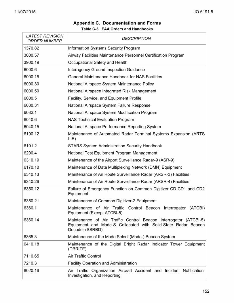
11/07/2015 JO 6191.5
152
Appendix C. Documentation and Forms Table C-3. FAA Orders and Handbooks
LATEST REVISION ORDER NUMBER DESCRIPTION
1370.82 Information Systems Security Program
3000.57 Airway Facilities Maintenance Personnel Certification Program
3900.19 Occupational Safety and Health
6000.6 Interagency Ground Inspection Guidance
6000.15 General Maintenance Handbook for NAS Facilities
6000.30 National Airspace System Maintenance Policy
6000.50 National Airspace Integrated Risk Management
6000.5 Facility, Service, and Equipment Profile
6030.31 National Airspace System Failure Response
6032.1 National Airspace System Modification Program
6040.6 NAS Technical Evaluation Program
6040.15 National Airspace Performance Reporting System
6190.12 Maintenance of Automated Radar Terminal Systems Expansion (ARTS IIIE)
6191.2 STARS System Administration Security Handbook
6200.4 National Test Equipment Program Management
6310.19 Maintenance of the Airport Surveillance Radar-9 (ASR-9)
6170.10 Maintenance of Data Multiplexing Network (DMN) Equipment
6340.13 Maintenance of Air Route Surveillance Radar (ARSR-3) Facilities
6340.26 Maintenance of Air Route Surveillance Radar (ARSR-4) Facilities
6350.12 Failure of Emergency Function on Common Digitizer CD-CD1 and CD2 Equipment
6350.21 Maintenance of Common Digitizer-2 Equipment
6360.1 Maintenance of Air Traffic Control Beacon Interrogator (ATCBI) Equipment (Except ATCBI-5)
6360.14 Maintenance of Air Traffic Control Beacon Interrogator (ATCBI-5) Equipment and Mode-S Collocated with Solid-State Radar Beacon Decoder (SSRBD)
6365.3 Maintenance of the Mode Select (Mode-) Beacon System
6410.18 Maintenance of the Digital Bright Radar Indicator Tower Equipment (DBRITE)
7110.65 Air Traffic Control
7210.3 Facility Operation and Administration
8020.16 Air Traffic Organization Aircraft Accident and Incident Notification, Investigation, and Reporting

11/07/2015 JO 6191.5
153
LATEST REVISION ORDER NUMBER DESCRIPTION
8200.1 United States Standard Flight Inspection Manual
8200.39 Flight Inspections of Precision Runway Monitors / Final Monitor Aid
8260.19 Flight Procedures and Air Space
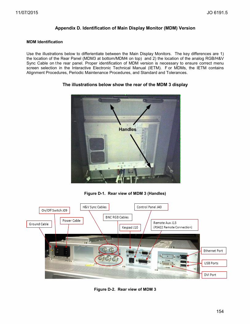
11/07/2015 JO 6191.5
154
Appendix D. Identification of Main Display Monitor (MDM) Version MDM Identification Use the illustrations below to differientiate between the Main Display Monitors. The key differences are 1) the location of the Rear Panel (MDM3 at bottom/MDM4 on top) and 2) the location of the analog RGB/H&V Sync Cable on t he rear panel. Proper identification of MDM version is necessary to ensure correct menu screen selection in the Interactive Electronic Technical Manual (IETM). F or MDMs, the IETM contains Alignment Procedures, Periodic Maintenance Procedures, and Standard and Tolerances.
The illustrations below show the rear of the MDM 3 display
Figure D-1. Rear view of MDM 3 (Handles)
Figure D-2. Rear view of MDM 3

11/07/2015 JO 6191.5
155
Appendix D. Identification of Main Display Monitor (MDM) Version
The illustrations below show the rear of the MDM 4 display
Figure D-3. Rear view of MDM 4
Figure D-4. Rear view of MDM 4 (Magnified)
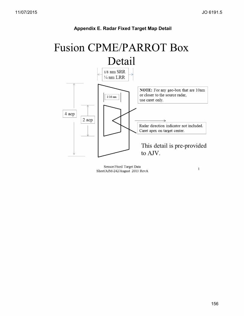
11/07/2015 JO 6191.5
156
Appendix E. Radar Fixed Target Map Detail
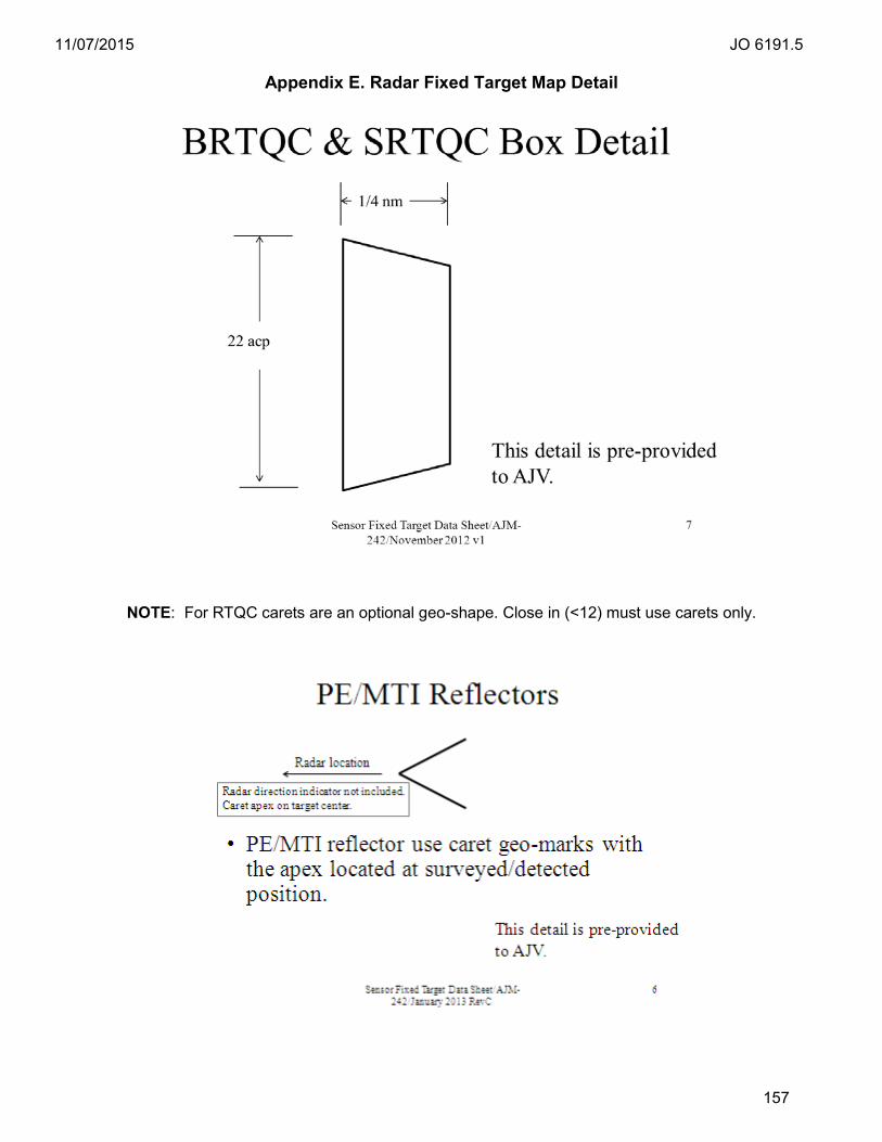
11/07/2015 JO 6191.5
157
Appendix E. Radar Fixed Target Map Detail
NOTE: For RTQC carets are an optional geo-shape. Close in (<12) must use carets only.

11/07/2015 JO 6191.5
158
Appendix F. ADS-B Fixed Beacon Target Map Detail
ADS-B Maps
Each dot is labeled with the appropriate radio station LID and adapted name. A caret with tip point on the dot assists in locating fixed target map marks. The dot is located at the RS lat/long.
SV028-03 VINLD
Solid dot scales to 608 feet in diameter.