Embed Size (px)
Citation preview
U.S. EPR FINAL SAFETY ANALYSIS REPORT
10.2 Turbine-Generator
This section describes the turbine-generator (TG) for the U.S. EPR.
The TG converts the thermal energy supplied by the main steam supply system (MSSS) into electrical energy.
The TG package interfaces with the MSSS at the high pressure (HP) turbine stop valves. It interfaces with the condensate and feedwater system at the low pressure (LP) turbine exhausts to the condenser, at the turbine extraction connections to the feedwater heaters, and at the moisture separator reheater (MSR) condensate and drain tank outlet connections to feedwater heaters and drain coolers. The generator terminals and enclosure connect to the isolated phase buses and ducts. The TG control system interfaces with the plant distributed control system (DCS).
10.2.1 Design Bases
The TG performs no safety-related functions and therefore has no nuclear safety-related design bases.
The TG principal design features include:
● The TG is designed for base load operation. The design of the TG has provisions for load follow operation for future consideration.
● The TG is capable of a load step (increase or decrease) of 10 percent of rated load below a 50 percent power level or a ramp rate (increase or decrease) of 5 percent per minute of actual load when the power level is in the range of 50 to 100 percent, without necessitating a turbine trip.
● The TG is designed to trip automatically under abnormal conditions.
● The TG load change characteristics are compatible with the instrumentation and control system which coordinates TG and reactor operation.
Tier 2 Revision 5 Page 10.2-1
● The TG is designed to accept a sudden loss of full load without exceeding design overspeed.
● The TG is designed to permit periodic testing of steam valves important to overspeed protection, electrical overspeed trip circuits and several other trip circuits under load.
● The failure of any single component does not cause rotor speed to exceed the design speed.
● The reheat stop and intercept valves are capable of closure concurrent with the HP turbine stop valves, or of sequential closure within an appropriate time limit, to make sure that turbine overspeed is controlled within acceptable limits.
U.S. EPR FINAL SAFETY ANALYSIS REPORT
● The valve arrangements and valve closure times are such that a failure of any single valve to close does not result in excessive turbine overspeed in the event of a TG trip signal.
● The TG is designed to provide proper drainage of related piping and components to prevent water induction into the turbine.
● The extraction steam check valves are provided at extraction connections and are capable of closing within an appropriate time limit to prevent reverse flow and maintain stable turbine speeds in the event of a TG trip signal.
● There is access to the TG equipment, including components and instrumentation associated with the overspeed protection system, during all operating conditions. Radiation shielding is not necessary in the TG area and is not provided.
● The TG provides extraction steam for seven stages of regenerative feedwater heating.
● The MSRs, MSR drain tanks, heat exchangers (except for generator hydrogen coolers), and vessels in TG auxiliary systems are designed to the requirements of ASME Boiler and Pressure Vessel (BPV) Code, Section VIII (Reference 1) (refer to Section 3.2). Turbine casings, internal components in the turbine, HP stop valves, HP control valves, reheat stop valves, intercept valves, generator casing, generator hydrogen coolers, and internal parts of the generator are designed to TG supplier standards.
10.2.2 General Description
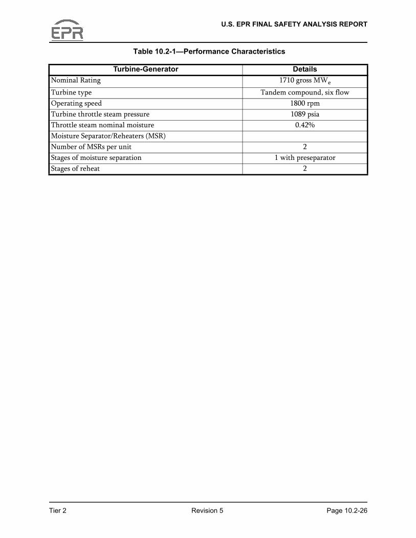
The TG package is shown in Figure 10.2-1—Turbine Generator System. Performance characteristics are provided in Table 10.2-1—Performance Characteristics.
The design and valves wide open (VWO) heat balances are presented in Section 10.1 (see Figures 10.1-1 and 10.1-2).
The TG package consists of an 1800 rpm, single-flow high pressure (HP) and a single-flow intermediate pressure (IP) turbine in a common casing; and three double-flow
Tier 2 Revision 5 Page 10.2-2
low pressure (LP) elements in tandem. The generator has a hydrogen-cooled rotor and de-ionized water-cooled stator. The generator is directly coupled to the turbine shaft. It is equipped with a collector for the static excitation system directly coupled to the generator shaft. Moisture separation and reheating of the steam is provided between the HP turbine and IP turbine by two combined MSR assemblies. The MSRs have two stages of reheating.
10.2.2.1 Component Description
Table 3.2.2-1 provides the seismic design and other design classification of components in the TG package.
U.S. EPR FINAL SAFETY ANALYSIS REPORT
10.2.2.1.1 TG Package Equipment
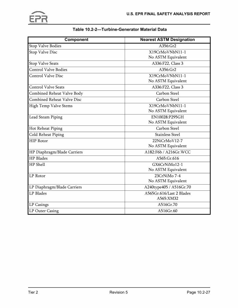
The TG package equipment includes the HP turbine stop and control valves, reheat stop and intercept valves, MSRs, MSR drain tanks, steam lead piping, cold reheat piping, hot reheat piping, TG control system, static excitation system and accessory equipment listed in Section 10.2.2.1.2. Table 10.2-2—Turbine-Generator Material Data, provides a list of material specifications for turbine-generator components.
HP/IP Turbine
This design features a combined HP/IP cylinder module, which contains the HP and IP steam paths in opposite flows, in a single-shell casing. The HP and IP steam inlets are located at the center of the module and the exhausts are at its two extremities.
HP Section
The HP section of the HP/IP module receives steam through four steam leads, one from each main steam control valve outlet. Normal operation utilizes full arc admission. The steam is expanded axially across the stationary and rotating blades. Extraction steam from the HP turbine at two locations supplies the sixth and seventh stages of feedwater heating and the heating steam to the first stage reheaters. HP turbine exhaust steam is collected in four cold reheat pipes. Most of the exhaust steam is routed to the MSR inlet, but part of it is diverted and supplies the fifth stage of feedwater heating.
IP Section
After removal of the water content and reheating in the MSRs, the steam is directed through four steam inlet pipes to the IP part of the HP/IP module, where it expands in stages of stationary and rotating blades. Extraction steam from the IP section of the HP/IP module supplies the third and fourth stages of feedwater heating.
LP Turbines
Tier 2 Revision 5 Page 10.2-3
Each of the three LP turbines receives steam from the IP outlet, through two steam pipe headers, one on each side of the turbines, fitted with expansion bellows. The LP turbines are identical, double-flow turbines. The LP turbines are each composed of an inner structure and an outer casing. The inner structure supports the LP blade carriers and the LP bearings. The outer casing collects the steam exhausted from the last LP stages. The outer casing is installed independently of the inner casing and is welded to the condenser which is directly anchored to the foundation slab. The outer casing moves freely with condenser thermal movements. A flexible sealing ring provided at each extremity maintains vacuum tightness between outer casing and the inner LP structure. The inner LP casing is provided with a piping header that allows water to be injected into the exhaust structures and prevents an excessive temperature rise during
U.S. EPR FINAL SAFETY ANALYSIS REPORT
no-load or low-load operation. Extraction steam from the LP turbines supplies the first and second stages of feedwater heating.
HP Main Stop and Control Valves
Four HP main stop and control valves admit steam to the HP turbine. The primary function of the main stop valves is to quickly shut off the steam flow to the turbine under emergency conditions. The primary function of the control valves is to control steam flow to the turbine in response to the turbine control system. Each control valve is operated by a single-acting, spring-closed servomotor opened by a high pressure fire-resistant fluid supplied through a servo valve. The stop and control valves close in approximately 0.30 seconds. The closing times for the main steam stop and control valves are based on preventing turbine overspeed following loss of full load. Each HP stop valve contains a permanent steam strainer to prevent foreign matter from entering the control valves and turbine.
Reheat Stop and Intercept Valves
The reheat stop and intercept valves are arranged between the MSRs and IP turbine inlet. The IP steam inlet is controlled by four sets of two series-mounted individual valves. One valve fulfills a turbine protection function (stop valve) and the other, a control and protection function (intercept valve). The valves are butterfly-type valves. The disc of each valve can rotate 90 degrees, from closed to open position, by means of a servomotor. The stop and intercept valves close in approximately 0.30 seconds. The closing times for the reheat stop and intercept valves are based on preventing turbine overspeed following loss of full load.
Control Fluid System
The control fluid system provides high pressure hydraulic fluid to open the main steam stop and control valves, and the reheat stop and control valves. The system includes two 100 percent capacity pumps, two 100 percent capacity filters, associated valves and instrumentation, hydraulic fluid regeneration system, and cooling system.
Tier 2 Revision 5 Page 10.2-4
The piping, valves, and equipment in the control fluid system are fabricated from stainless steel, including the fluid reservoir. Flow from the discharge of the control fluid pump flows through a 25 micron filter before being routed to the valve actuators. The piping connection at each valve actuator is with a flexible hose to protect the control fluid piping from vibration. The system also includes:
● Closed loop cooling system that routes fluid from the reservoir through two 100 percent coolers and back to the tank to maintain the fluid temperature at a uniform value. The cooling system has a dedicated pump and heat exchanger bypass.
● Closed loop regeneration system that pumps fluid from the reservoir through a chemical filter followed by a particulate filter to maintain the manufacturer’s
U.S. EPR FINAL SAFETY ANALYSIS REPORT
recommended characteristics of the control fluid, before being routed back to the reservoir. The regeneration system has a dedicated pump.
● Control fluid reservoir includes an inlet breather desiccant filter to minimize the amount of moisture entering the reservoir.
● Control fluid reservoir includes an electrical heater that can be used to heat the control fluid during startup and prolonged shutdown.
Control fluid from the valve actuators is collected in two stainless steel drain headers, one on each side of the turbine. These drain headers combine into one common drain header, which is sloped back to the control fluid reservoir. The drain headers are sized to handle the maximum control fluid flow requirements maintaining the required valve stroke times. See Figure 10.2-4 for a representative schematic diagram of the control fluid drain lines.
Problems identified in NUREG-1275 have been addressed by the design of the control fluid system, materials of construction and system/component testing requirements specified in Section 10.2.2.12.
Extraction Non-Return Valves
Non-return valves are used in selected turbine steam extraction lines to minimize the potential for turbine overspeed and prevent water induction into the turbine. The number of valves, type of valve, and maximum steam volume allowable between the valve and turbine extraction nozzle will be in accordance with the turbine manufacturer’s requirements and the requirements of ANSI/ASME TDP-1-1998 (Reference 12).
Turbine extraction steam lines that include non-return valves will also include a motor-operated isolation valve.
Two types of non-return valves are provided:
● Air-assisted swing check valve with piston actuator, air-to-open, spring-to-close
Tier 2 Revision 5 Page 10.2-5
type are used on the high pressure extraction lines to feedwater heaters 6 and 7, and on the intermediate extraction lines to feedwater heaters 3 and 4 to prevent turbine overspeed.
● Swing check valve without actuator type is used on the extraction line to the deaerating feedwater heater to prevent water induction into the turbine. This extraction line does not require an air-assisted valve since the reheat stop and control valves are installed in the steam line downstream of the MSR. The reheat valves prevent an uncontrolled overspeed from occurring in case of steam backflow to the turbine.
U.S. EPR FINAL SAFETY ANALYSIS REPORT
Non-return valves are not required for the extraction steam lines to feedwater heaters 1 and 2 because of the low pressure in these heaters.
The air-assisted check valves are held open with instrument air and the valve can operate as a non-actuated swing check valve. The actuator will return to the closed position when a trip signal is received by the solenoid valve used to supply air to the actuator. The solenoid valve shifts to the exhaust position causing a loss of inlet pressure on the quick exhaust valve. Loss of inlet pressure causes the quick exhaust valve to rapidly vent the actuator piston chamber allowing the actuator spring to rotate the valve shaft and push the valve disc into the flow stream. Closure time of the non-return valve is within one second after the solenoid valve receives a trip signal. A test switch on the solenoid valve allows both the check valve and the solenoid valve to be periodically exercised. Loss of air supply or power to the extraction non-return valve actuator will cause the actuator to move to the close position under spring force. Figure 10.2-5—Non-Return Valve Air Schematic is a representative schematic diagram of the air line to the non-return valve actuator.
The compressed air system is described in Section 9.3.1.
Generator
The generator is a four-pole machine directly driven by the turbine and supplies the step-up transformer with high voltage electrical output. The field winding is directly cooled by hydrogen gas. The stator winding is directly cooled by an internal circulation of de-ionized water (stator cooling water). The generator static excitation system is controlled by an automatic voltage regulator. The generator rotor is made from a solid alloy steel forging with high tensile strength. The slots for the field coils are milled in the central body of the rotor.
The frame, which constitutes the outer envelope, is made of an assembly of heavy welded steel plates, forming a cylindrical shell. The machine is gas tight and the hydrogen coolers are located in the frame itself. Hydrogen detectors are located around the generator hydrogen system to provide warning of a hydrogen leak. The
Tier 2 Revision 5 Page 10.2-6
generator hydrogen system is designed in accordance with NFPA 55 (Reference 2).
The generator auxiliaries include cooling system, gas supply and shaft sealing circuits.
Moisture Separator Reheaters
Two cylindrical-shell, combined MSRs are installed in the steam path between the HP and IP turbines. The MSRs dry and reheat the HP turbine steam exhaust. Cold reheat steam is piped into the bottom of the MSR. Moisture is removed in chevron type moisture separators, drained to the moisture separator drain tanks and then drained and pumped to the deaerator/feedwater storage tank. The dry steam passes across two stages of reheaters, which are supplied with turbine extraction steam (first reheating
U.S. EPR FINAL SAFETY ANALYSIS REPORT
stage) and main steam (second reheating stage). The steam is then routed to the hot reheat stop valves/intercept valves, which are located upstream of the IP turbine inlet nozzles. The first stage reheaters drain via drain tanks to the HP heaters, and the second stage reheaters drain via drain tanks to the high pressure drain coolers. Safety valves are provided on the MSR for overpressure protection.
10.2.2.1.2 TG Accessories
The TG accessories include:
● Bearing lubrication oil system.
● Electro-hydraulic control system.
● Control valves for second stage reheater steam supply.
● Extraction check valves.
● Turbine drain system.
● Turning gear.
● Turbine gland sealing system.
● LP outer casing spray system.
● Hydrogen and carbon dioxide systems.
● Generator seal oil system.
● Stator cooling water system.
● TG supervisory instrument (TSI) system.
10.2.2.2 TG Foundation
The TG foundation structure is a spring-mounted support system that provides a low-
Tier 2 Revision 5 Page 10.2-7
tuned, turbine-pedestal foundation. The springs dynamically isolate the TG deck from the remainder of the structure in the range of operating frequencies, thus allowing for an integrated structure below the turbine deck. The structure of the LP module is designed so that the outer casing is independent from the inner casing (i.e., the LP outer casing is directly and rigidly attached to the condenser and a flexible seal ring maintains a vacuum tight connection between the outer casing and the LP inner casing). The LP inner casing and bearings are directly supported on the turbine pedestal.
The foundation design consists of a reinforced concrete deck mounted on springs and supported on columns and structural system that take the load from the table top to
U.S. EPR FINAL SAFETY ANALYSIS REPORT
the Turbine Building foundation. The lateral bracing under the TG deck also serves to brace the building frame. This "integrated" design reduces the bracing and number of columns required in the building. Additionally, the spring-mounted design allows for dynamic uncoupling of the TG foundation from the substructure. The spring-mounted support system is much less site-dependent than other turbine pedestal designs because the soil structure is decoupled from turbine dynamic effects. The TG foundation consists of a concrete table top, while the substructure consists of supporting beams and columns. The structure below the springs is designed independent of vibration considerations.
10.2.2.3 Cycle Description
The main steam flows from the MSSS through the four combined main steam stop and control valves into the HP turbine. After expanding in the HP blading, the steam passes through the steam exhaust branches into the cold reheat piping system. Steam passes to each of the two MSRs in two cold reheat lines per MSR.
The first stage reheat steam is supplied from the first extraction from the HP turbine. The second stage reheat steam is supplied from the MSSS, including control valves to control and shut off the steam flow. Condensed steam from the second stage reheater is drained to a drain tank and then flows to the shell side of a drain cooler, which is the last stage of feedwater heating. Condensed steam from the first stage reheater is drained to a drain tank and then flows to the shell side of the No. 6 feedwater heaters. The moisture removed from the MSRs is drained to a drain tank, and then to the de-aerator.
Two extraction lines are connected to the HP turbine. The steam goes to the HP feedwater heaters No. 7 and No. 6, respectively. The steam passes from the two MSRs into the hot reheat piping system and then through four LP stop-intercept butterfly valve assemblies to the IP turbine.
The IP turbine has two extraction stages to LP feedwater heaters No. 4 and No. 3, respectively. Steam exhausts from the IP turbine outlets to the three LP turbines
Tier 2 Revision 5 Page 10.2-8
through two steam pipes.
Each LP turbine has three extraction stages to LP feedwater heaters No. 2 and No. 1.
The turbine casings, turbine valves and turbine piping are provided with drain valves or traps for removing condensate during startup and transient operation.
The turbine shaft seals and the main steam valve glands are fitted with connections to the gland steam system.
U.S. EPR FINAL SAFETY ANALYSIS REPORT
10.2.2.4 Excitation System
The excitation system is static with a solid-state voltage regulator. Excitation power is obtained from dry type, indoor excitation transformers, which are directly connected to the main generator IPB. The brushgear includes the enclosure with coolers, filters, moisture control, brush holders and brushes; and the slip rings mounted on a generator shaft extension. The exciter rectifiers are arranged in a full-wave bridge configuration and protected by a series-connected fuse. The turbine building closed cooling water system (TBCCWS) provides cooling water to the brushgear air-to-water heat exchangers. The TBCCWS is addressed in Section 9.2.10.
10.2.2.5 TG Control System
The TG control system is a fault-tolerant control system with the following features:
● Triple processors and two-out-of-three trip logic.
● Automatic synchronizing capabilities.
● Automatic TG startup and shutdown control system functions as well as separate automatic startup and shutdown functions for each individual auxiliary system. These automatic functions are separate and independent of each other.
● Automatic and manual controls in the control room to preheat the turbines, start and load the unit from no load to full load, adjust load during continuous operation, perform all normal (periodic) test functions, and unload the unit for shutdown. Automatic controls are based, in part, on thermal ramp rate, acceleration through critical speeds, rotor stress and heat soak (temperature gradient minimization) of cylinders, shells and rotors.
● Redundant communication paths between processors within the turbine control system.
● Digital speed governor.
● On-line redundancy in a hot standby arrangement for turbine governor
Tier 2 Revision 5 Page 10.2-9
processors.
● Redundant power supplies for processors, chassis, input/output (I/O) modules, and field devices with alarm notification of any malfunction.
● Two redundant communication paths for each turbine-generator package from the TG control system main control cabinet to the operator workstation.
● Two redundant communication paths within the TG control system connecting to the plant DCS.
● Provisions for manually initiated individual valve or valve pair on-line testing of the main steam stop, control, reheat stop and intercept valves.
U.S. EPR FINAL SAFETY ANALYSIS REPORT
The following conditions initiate a turbine trip:
● Low bearing oil pressure.
● Low control oil (hydraulic fluid) pressure.
● High condenser back pressure.
● Turbine overspeed.
● Thrust bearing excessive wear.
● Remote trip (reactor trip).
● Excessive ‘Time of Operation above No Flow Load’ (initiated by generator reverse power relay after time delay specified by turbine designer).
● Loss of speed signals.
● Journal bearing high vibration.
● LP turbines outer casing high temperature.
● Hardwired manual trip button located in the main control room.
● Hardwired manual trip button located close to the turbine front end bearing.
There is one set of three control speed sensors and one spare speed sensor. The three control speed sensors are totally independent of the overspeed protection systems. The analog signals from these sensors are sent to the two redundant speed governors, located in the TGC cabinet, and processed to give main steam and reheat control valve position commands. The two speed governors provide on-line redundancy in a hot standby arrangement.
The redundancy of the speed governors allows for safe valve control. If one speed governor fails, the second speed governor still measures speed and controls the valve
Tier 2 Revision 5 Page 10.2-10
position. If both speed governors fail, the triple redundant protection system will order a turbine trip, providing for an overall speed control system that is fail-safe.
Valve opening actuation is provided by the control oil (electro-hydraulic) system that is independent of the bearing lubrication system. Valve closing actuation is provided by springs and steam forces upon reduction or relief of hydraulic fluid pressure. The system is designed so that loss of fluid pressure for any reason leads to valve closing and subsequent turbine trip.
Steam valves are provided in series pairs. The stop valves are tripped by the trip system (overspeed and other trips); the control valves are modulated by the governing system and are also actuated closed by the trip system.
U.S. EPR FINAL SAFETY ANALYSIS REPORT
The loss of one or two of the governor speed signals will cause an alarm; loss of all three governor speed signals will cause the turbine to trip.
The loss of one of the overspeed protection system speed signals will cause an alarm; loss of two overspeed protection system speed signals will cause the turbine to trip.
Loss of one of the turbine protection trip channels will cause an alarm; loss of two out of three trip channels will cause the turbine to trip.
10.2.2.6 Speed Control
Speed control is used during startup and has a minimum adjustable setpoint range of zero to 100 percent of rated speed. It has the following features:
● The speed governor for normal speed-load control fully closes the control and intercept valves at 103 percent of rated turbine speed.
● The maximum rotational speed attainable upon loss of a single normal governing device does not exceed 103 percent of rated turbine speed.
10.2.2.7 Load Control
Load control is used during normal operation and has a setpoint range of zero to 100 percent of maximum capability. Load control controls megawatts (MW) based on the plant MW setpoint signal provided by the plant DCS. It has the following features:
● Automatic controls to avoid unnecessary turbine trip and to permit subsequent operation at house load (i.e., load required to run station auxiliaries) in the event of a load rejection from 100 percent load.
● Automatic controls to rematch the TG loads following a momentary (7 Hz or less) mismatch between generator load and generator power, without loss of synchronization during load mismatch transients, up to full power.
10.2.2.8 Valve Control
Tier 2 Revision 5 Page 10.2-11
The flow of main steam entering the HP turbine is controlled by four stop valves and four governing control valves. Each stop valve is controlled by an electro-hydraulic actuator, so that the valve is either fully open or fully closed. The function of the stop valves is to shut off the steam flow to the turbine when required. Actuation of the electrical overspeed trip system devices closes the stop valves.
The turbine control valves are positioned by electro-hydraulic servo actuators in response to signals from their respective flow control unit. The flow control unit signal positions the control valves for wide-range speed control through the normal turbine operating range and for load control after the TG unit is synchronized.
U.S. EPR FINAL SAFETY ANALYSIS REPORT
The reheat stop and intercept valves, located in the hot reheat lines at the inlet of the IP turbines, control steam flow to the IP turbines. During normal operation of the turbine, the reheat stop and intercept valves are fully open. The intercept valve flow control unit positions the valve during startup and normal operation and closes the valve rapidly on loss of turbine load. The reheat stop valves close completely on turbine overspeed and turbine trip.
10.2.2.9 Overspeed Protection
Overspeed protection for the turbine is provided by:
● Electro-hydraulic governor system.
● Primary electrical overspeed trip system.
● Backup electrical overspeed trip system.
● Manual trip button located in the main control room and manual trip button local to the turbine.
A protective trip system is provided to quickly close the main steam stop and control valves, the reheat stop and intercept valves, and the extraction steam non-return valves in the event of an unsafe condition or to provide overspeed protection. The system is designed to minimize false and spurious trips during normal operation and allow testing of the trip system during operation. A power load imbalance function is provided, which compares turbine and generator load and initiates an appropriate momentary control valve closure when the turbine load exceeds the generator load by a specified amount.
Following a loss-of-load event, the governor system is designed to limit the turbine speed to 108 percent of nominal speed. The maximum expected overspeed following a full-load rejection at valves wide open, assuming a governor system failure and an overspeed protection system trip is approximately 117 percent.
Tier 2 Revision 5 Page 10.2-12
The steam turbine has two redundant and diverse electrical overspeed systems that meet the single failure criterion. The two overspeed protection systems are redundant from the speed probes to the turbine trip relays. Both overspeed protection systems have three independent speed probes and signal conversion modules acting on one of three electronic tripping channels. Each independent electrical overspeed trip system is designed and manufactured by a different vendor. Each vendor directly manufactures their system components (e.g., motherboards, sensors) and develops diverse software to transform the analog speed sensor signal into a digital signal. Software between the two overspeed protection systems will be different in parameters, dynamics, or logic. There are no components, process inputs, or process outputs shared between the two systems. Each system will be installed in a separate cabinet with separate power sources. Figure 10.2-2—Overspeed Protection System
U.S. EPR FINAL SAFETY ANALYSIS REPORT
Schematic shows the separate source of power supply to each system and how the sensors are treated by independent motherboards.
The two overspeed protection systems each have three separate electronic boards for signal conversion and activation of an overspeed trip. Digital trip output signals from the motherboards of each overspeed protection system will interrupt the power of separate relays as shown in Figure 10.2-2. The trip signals from the two overspeed protection systems are isolated from and independent of each other.
The electrical overspeed protection system has a minimum Safety Integrity Level rating of 3, in accordance with IEC 61508-1, “Functional Safety of Electrical/Electronic/Programmable Electronic Safety-Related Systems” (Reference 13).
The electrical overspeed trip system provides acceptable diversity with respect to SRP Section 10.2 acceptance criteria. The mechanical and electrical systems generate a turbine trip by dumping hydraulic fluid from the valve actuators to the hydraulic fluid tank.
Common cause failures of the overspeed protection systems are prevented through use of redundant and diverse hardware and software.
Disadvantages of the mechanical overspeed trip system include the following:
● Limited accuracy and reliability.
● No on-line diagnostics or surveillance available.
● Difficult to set, maintain and calibrate.
● Requires high risk test procedures.
Advantages of the electrical overspeed trip system include the following:
● Improved accuracy, safety and reliability.
Tier 2 Revision 5 Page 10.2-13
● Automated calibration, diagnostics and alarms.
● Eliminates the need for high risk tests.
The mechanical system cannot be set to a precise trip set point at a given speed. Over time of operation the trip set point can drift, changing the point where the system trips the turbine. The only way the system can be tested to confirm the trip set point, or to verify that the system is operational, is to overspeed the turbine to the trip speed. This test unnecessarily stresses the turbine rotor.
The electrical overspeed system can be tested during operation without actually overspeeding the turbine. The trip point can be set within one percent of the desired
U.S. EPR FINAL SAFETY ANALYSIS REPORT
trip speed. The system provides feedback on failure of system components and provides a speed signal back to the turbine control system to monitor speed sensor accuracy. The electrical overspeed system also allows redundancy in the components and two out of three trip logic, which will minimize the number of false trips of the turbine.
The electrical system provides a safer, more reliable, overspeed protection system than the mechanical system. It can be tested during operation, provides continuous status feedback and alarms of component failures or signal discrepancies, and can be tested without stressing the turbine in an overspeed event.
The trip block provides an interface between the electrical and hydraulic systems and consists of three trip solenoid valves. The three independent electronic channels energize three fail safe solenoid valves (trip by loss of power). Each solenoid valve acts on two hydraulic relays of the trip block in order to perform the hydraulic two-out-of-three trip voting. The turbine will be tripped when at least two solenoid valves are de-energized. An interruption and discharge of the fluid supply by the trip block will cause the high pressure and intermediate pressure valves to close by spring action. Figure 10.2-3—Turbine Trip Block Schematic provides a schematic of the trip block. There are three separate flow channels between the solenoid valves and plate valves, and a common inlet and outlet header. There are two separate fluid drain lines back to the hydraulic tank, one from the solenoid valves and one from the plate valves. Failure of the hydraulic piping between the trip block and the valve actuator, or between the hydraulic fluid tank and the valve actuator will cause a loss of fluid pressure, which closes the valves. Thus, the trip block is designed fail safe, due to the fact that any failure (e.g., loss of power, loss of safety fluid pressure, fluid leak) will cause a steam turbine trip.
When the trip block dumps the hydraulic fluid to the control fluid tank, low pressure occurs in the control fluid supply line to the main steam and reheat valves. Low pressure in the fluid supply line causes the exhaust valve on each actuator to trip and exhaust the fluid from the operating piston chamber of the actuator to the opposing
Tier 2 Revision 5 Page 10.2-14
chamber and the fluid drain line to the control fluid tank. Pressure in the operating piston chamber rapidly goes to atmospheric and the valves close by spring action.
The speed sensors are located near the turbine front bearing so they are protected from the effects of missiles and pipe breaks.
The primary electrical overspeed trip system fully closes the valves at about 110 percent of rated speed. An independent and redundant backup electrical overspeed trip circuit is provided to fully close these valves at about 111 percent of rated speed. The TG rotor is designed to withstand 120 percent of rated speed.
U.S. EPR FINAL SAFETY ANALYSIS REPORT
Each of the digital output signals indicating overspeed trip activation is also sent to the triple redundant turbine protection system for indication of overspeed activation on the human machine interface. Signals from the overspeed protection systems are hardwired to the relays in each of the protection channels, which are hardwired to the solenoid valves of the trip block. These signals are not processed in the turbine protection system.
When the turbine is tripped, the turbine system extraction non-return valves receive a closing signal. The turbine tripped signal is caused by low control fluid pressure from two out of three analog measurements.
The actuation of the turbine protection system does not rely on components in the electro-hydraulic control system. Conversely, turbine trip initiation devices are not used for normal control of the unit.
Provisions for online testing of the electrical overspeed trip system, including individual trip devices, are provided.
The three overspeed protection channels are tested individually on a daily basis. The two remaining channels are operational for turbine overspeed protection during the daily test. A trip signal from one of the operational protection channels during a channel test will cause the turbine to trip.
During the test of a protection channel the following occurs:
● The channel overspeed card artificially increases the channel turbine speed.
● An alarm is displayed that states the channel is tripped.
● The solenoid valve is de-energized, which opens the plate valves.
If the solenoid valve or plate valves do not function correctly, an alarm is generated. The procedure is then repeated for the remaining two channels.
Tier 2 Revision 5 Page 10.2-15
After receipt of a trip signal, the hydraulic controllers for the main stop, control, reheat stop and intercept valves close off these valves quickly to preclude an unsafe turbine overspeed. The response of the controllers considers the residual steam in the piping between the valves and the turbine.
After receipt of a trip signal from the turbine protection system, the air supply solenoid valve of each extraction non-return valve will move to the exhaust position to rapidly close the check valves to preclude an unsafe turbine overspeed because of steam backflow into the turbine. The response time and location of the valves considers the residual steam in the extraction piping between the valve and the turbine. The air supply solenoid valve will send the valve actuator to the closed position upon loss of power.
U.S. EPR FINAL SAFETY ANALYSIS REPORT
In the case of a turbine trip, the failure of one extraction non-return valve to close will not cause a turbine overspeed. The air-assisted extraction non-return valves are credited to prevent the turbine from exceeding the design overspeed limit of 120 percent of rated speed.
A COL applicant that references the U.S. EPR design certification will provide a reliability evaluation of the overspeed protection system, which includes the inspection, testing, and maintenance requirements needed to demonstrate reliable performance of the system.
10.2.2.10 Turbine Supervisory Instrumentation
The TSI provides:
● Acquisition of data for the turbine control system and supervision in the main control room (MCR).
● Treatment of signals.
● Monitoring and diagnostics.
● Provides power to the vibration, expansion and displacement sensors.
The TSI interfaces with the plant DCS to furnish information on operating parameters in the MCR. The TSI is dedicated to processing the monitoring of sensors. Establishing alarm and trip thresholds, associated with these measurements, will be performed by the turbine protection system.
Each measurement important to the protection and proper operation of the turbine generator is monitored by the TSI and displayed as an alarm when the first threshold is passed over (such as high or low level). If the second threshold is passed over (such as high-high or low-low level), it leads to a turbine trip through the triple redundant steam turbine protection (STP) system. Any measurement single failure (one out of three measurement disturbance or drifting) is communicated to the operator through
Tier 2 Revision 5 Page 10.2-16
an alarm sheet). If two out of three measurements fail, it leads to a turbine trip through the STP system. The operator is informed of any anomaly and has access to the corresponding alarm sheet in order to identify the failure location.
10.2.2.11 Other Protective Systems
Additional protective features of the turbine and steam system are:
● MSR safety relief valves.
● Rupture diaphragms on the LP turbine outer casings.
● Turbine water induction protection systems on the extraction steam lines.
U.S. EPR FINAL SAFETY ANALYSIS REPORT
10.2.2.12 Turbine Inservice Inspection and Testing
Major TG system components are readily accessible for inspection and are available for testing during normal plant operation.
The turbine inservice inspection and test program is used for the governor and overspeed protection system to provide reasonable assurance that flaws or component failures are detected in the overspeed sensing and tripping subsystems, main steam control and stop valves, reheat steam intercept and stop valves or extraction steam non-return valves; or any other condition that could lead to an overspeed condition above that specified by the design overspeed. The inservice inspection program for operability of the governor and overspeed protection system includes, at a minimum, the following provisions:
● For turbine governor and overspeed protection systems, at intervals of approximately three and one-third years, during refueling or maintenance shutdowns coinciding with the inservice inspection schedule required by the ASME BPV Code, Section XI, (Reference 3) for reactor components, at least one main steam stop valve, one main steam control valve, one reheat stop valve, one reheat intercept valve and one of each type of steam extraction valve are dismantled for examination. Visual and surface examinations of valve seats, disks and stems are conducted. Valve bushings are inspected and cleaned and bore diameters are checked for proper clearance. If any valve is shown to have flaws or excessive corrosion or improper clearances, the valve is repaired or replaced and other valves of that type are also dismantled and inspected.
● The main steam stop and control valves, reheat stop and intercept valves, and steam extraction non-return valves are exercised weekly at a minimum of 97% load and observations of the valve motions are made.
● The components of the electro-hydraulic governor system are automatically tested when the turbine is in operation on a daily basis.
● The components of each channel of the primary and backup overspeed protection systems, including the trip block valves, are automatically tested on a daily basis when the turbine is in operation.
Tier 2 Revision 5 Page 10.2-17
● Rate of seat leakage of the main steam stop valves is tested at each refueling.
● The valve closure time and stem thrust of the main steam stop and control valves, and the reheat stop and intercept valves, is tested at each refueling, including a functional test of the hydraulic protection circuit.
● Condition of the valve seats of the extraction non-return valves will be inspected in accordance with the valve manufacturer’s recommendations.
● The control room manual trip and local manual trip are tested prior to startup after each outage or if maintenance has been performed on either system.

U.S. EPR FINAL SAFETY ANALYSIS REPORT
A COL applicant that references the U.S. EPR design certification will provide the site-specific inservice inspection program, inspection intervals, and exercise intervals consistent with the turbine manufacturer’s recommendations for the main steam stop and control valves, the reheat stop and intercept valves, and the extraction non-return valves.
10.2.3 Turbine Rotor Integrity
Turbine rotor integrity is provided by the integrated combination of material selection, rotor design, fracture toughness requirements, inspections and tests. The combination results in a very low probability of rotor failure.
10.2.3.1 Materials Selection
Turbine rotors are made from vacuum melted or vacuum degassed Ni-Cr-Mo alloy steel by processes that minimize flaw occurrence and provide adequate fracture toughness. Tramp elements are controlled to the lowest practical concentrations consistent with good scrap selection and melting practice, and consistent with obtaining adequate initial and long-life fracture toughness for the environment in which the parts operate. The sulfur and phosphorous concentrations are specified below 0.020 percent (chemical product analysis), which is in accordance with specifications ASTM A470 (Reference 11) and ASTM A471 (Reference 4).
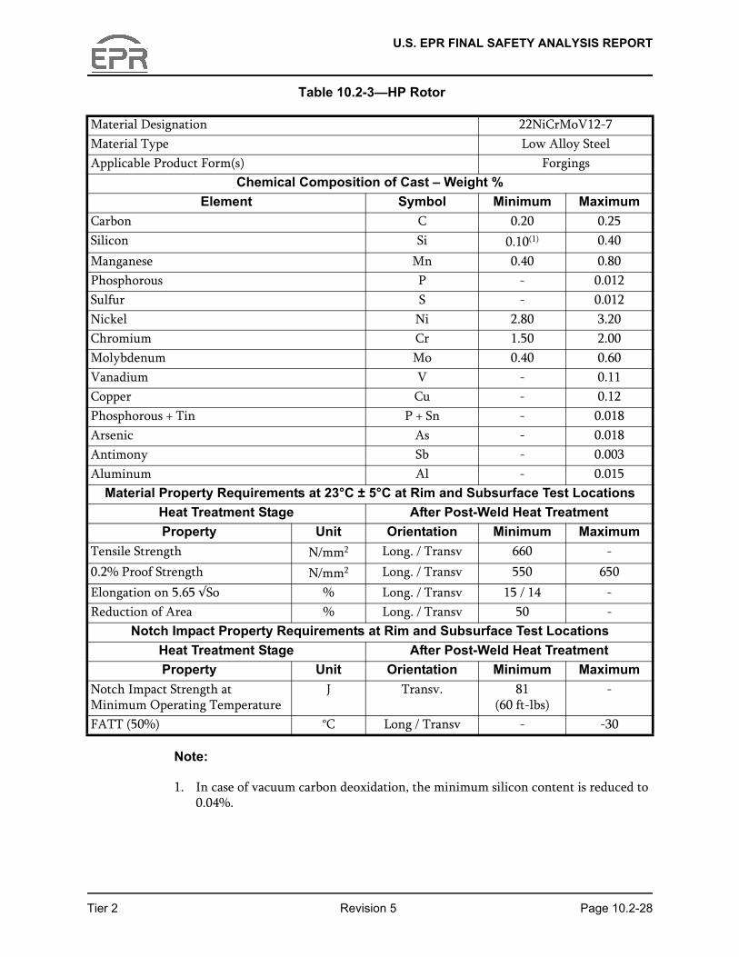
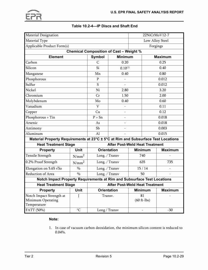
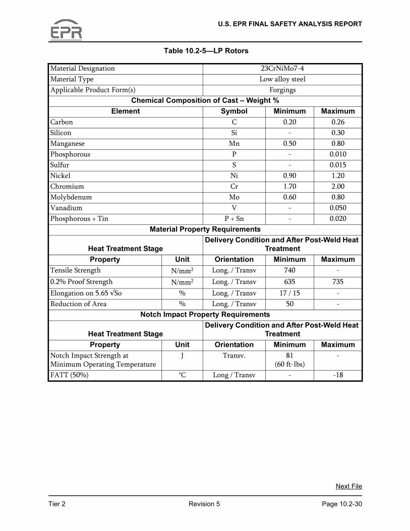
The chemical compositions and mechanical properties used for the turbine rotors are given in Table 10.2-3—HP Rotor, Table 10.2-4—IP Discs and Shaft End, and Table 10.2-5—LP Rotors.
A cast chemical analysis is performed on each rotor forging element. It shall conform to the requirements of the material specification.
Tensile test pieces and procedures are in accordance with the requirements of ASTM A370.
The turbine materials have the lowest fracture appearance transition temperatures
Tier 2 Revision 5 Page 10.2-18
(FATT) and highest Charpy V-notch (Cv) energies obtainable, on a consistent basis, from water quenched Ni-Cr-Mo material at the sizes and strength levels used. The processing is controlled to maintain the following:
● 50 percent FATT less than 0°F for the LP turbine rotors.
● Charpy V-notch energy at the minimum operating temperature of each LP rotor in the tangential direction greater than or equal to 60 ft-lbs.
The form, dimensions and procedure used for Charpy V-notch impact tests are in accordance with the requirements of ASTM A370. The average value for the Charpy V-notch impact strength obtained on the three test pieces shall not be lower than
U.S. EPR FINAL SAFETY ANALYSIS REPORT
specified for the material. Not more than one individual value shall be below the specified value and no individual value shall be lower than 70 percent of the specified value.
Curves of Charpy V-notch absorbed energy and percentage crystallinity versus test temperature are plotted for FATT determination. The method of measurement of crystallinity conforms to the requirements of ASTM A370. The FATT is determined as the temperature corresponding to 50 percent crystallinity using a minimum of ten test pieces.
Table 10.2-2—Turbine-Generator Material Data, provides a list of material specifications for turbine-generator components. Actual material properties of turbine rotors are obtained through precise destructive tests of actual samples from each turbine rotor. A COL applicant that references the U.S. EPR design certification will provide applicable material properties of the site-specific turbine rotor, including the method of calculating the fracture toughness properties.
10.2.3.2 Fracture Toughness
As noted in Section 10.2.3.1, a suitable material toughness is obtained through the use of selected materials to produce a balance of adequate material strength and toughness and maintain a reasonable level of safety, while simultaneously providing high reliability, availability and efficiency during operation.
Stress calculations are performed taking into account centrifugal loads and thermal gradients, wherever applicable, on all major components (e.g., rotors, casings, blades). Fracture mechanics calculations are performed on the rotors taking into account the maximum acceptable size defect for U.S. standards. Calculations verify that the initial defect, after increasing due to fatigue during the equipment lifetime, does not propagate and remains non critical by a large margin as regards to brittle fracture.
The ratio of the fracture toughness, Klc (as calculated from the material tests performed on the rotor) to the maximum tangential stress at speeds from normal to 120 percent of
Tier 2 Revision 5 Page 10.2-19
the rated speed, is at least 2 √in, at minimum operating temperature. Adequate fracture toughness to prevent brittle fracture during startup is verified by calculating startup curves specifying appropriate startup temperature and sufficient warm-up time.
The acceptance criteria for UT inspections are:
● 3 mm maximum for discs (depending on the areas).
● 5 mm maximum for shaft ends (depending on the areas).
U.S. EPR FINAL SAFETY ANALYSIS REPORT
Fracture toughness properties are calculated from material tests and can be obtained by any of the following methods:
● Testing of the actual material of the turbine rotor to establish the Klc value at normal operating temperature.
● Testing of the actual material of the turbine rotor with an instrumented Charpy machine and a fatigue precracked specimen to establish the Klc (dynamic) value at normal operating temperature. If this method is used, Klc (dynamic) is used in lieu of Klc (static) in meeting the toughness criteria.
● Estimating of Klc values at various temperatures from conventional Charpy and tensile data on the rotor material using methods are presented in J. A. Begley and W. A. Logsdon, Scientific Paper 71-1E7-MSLRF-P1 (Reference 5). This method of obtaining Klc is used only on materials which exhibit a well-defined Charpy energy and fracture appearance transition curve and are strain-rate insensitive.
● Estimating “lower bound” values of Klc at various temperatures using the equivalent energy concept developed by F. J. Witt and T. R. Mager, ORNL-TM-3894 (Reference 6).
A COL applicant that references the U.S. EPR design certification will provide applicable site-specific turbine disk rotor specimen test data, load-displacement data from the compact tension specimens and fracture toughness properties.
10.2.3.3 High Temperature Properties
There is no influence on stress rupture properties because the maximum operating temperature, the basis for determining the design temperature of rotors, is below the re-crystallization and creep temperatures.
10.2.3.4 Turbine Rotor Design
The high pressure (HP) part of the high/intermediate pressure (HIP) rotor assembly is one forged section. The intermediate pressure (IP) part of the HIP rotor assembly consists of three forged sections. The HIP rotor assembly is a welded rotor consisting
Tier 2 Revision 5 Page 10.2-20
of four forgings. The rotors of the LP turbines are a welded rotor design.
The turbine assembly is designed to withstand normal operating conditions, anticipated transients, and accidents resulting in a turbine trip without loss of structural integrity. The design of the turbine assembly meets the following criteria:
● The design overspeed of the turbine is 120 percent of rated speed, which is higher than the highest anticipated speed resulting from a loss of load. The primary overspeed trip system fully closes the valves at about 110 percent of rated speed. An independent and redundant backup electrical overspeed trip circuit is provided to fully close these valves at about 111 percent of rated speed.
U.S. EPR FINAL SAFETY ANALYSIS REPORT
● The combined stresses in the low-pressure turbine rotor at design overspeed due to centrifugal forces and thermal gradients do not exceed 75 percent of the minimum specified yield strength of the material, or 75 percent of the measured yield strength in the weak direction of the materials if tensile tests are performed on the actual rotor material.
● The turbine shaft bearings are able to withstand any combination of the normal operating loads, anticipated transients and accidents resulting in a turbine trip.
● The natural critical frequencies of the turbine shaft assemblies between zero speed and 20 percent overspeed are controlled by design and during operation stages to minimize adverse effects to the unit during operation.
● The turbine rotor design facilitates inservice inspection of high stress regions.
● Stress corrosion cracking is considered as a degradation mechanism for crack growth.
10.2.3.5 Turbine Rotor Preservice Inspections and Testing
The following preservice inspections are performed during manufacture:
● Forged or welded rotors are rough machined prior to heat treatment.
● Each finished forged or welded rotor is subjected to 100 percent volumetric (ultrasonic), surface and visual examinations using procedures and acceptance criteria equivalent to those specified for Class 1 components in the ASME BPV Code, Section III (Reference 7) and Section V (Reference 8). Before welding or brazing, all surfaces prepared for welding or brazing are surface examined. After welding or brazing, all surfaces exposed to steam are surface examined, giving particular attention to stress risers and welds. Welds are ultrasonically examined (100 percent volumetric examination), equivalent to examinations in Reference 8. Each weld in the turbine rotor assembly is subjected to 100 percent examination in the radial, longitudinal, and tangential directions. Acceptance criteria shall be the most stringent between manufacturer’s standards and ASME Code Section III, subsection NB-5300 (Reference 10).
Tier 2 Revision 5 Page 10.2-21
● Visual inspection of the pin holes used to assemble the blades to the rotor disc includes an examination performed with the naked eye, and where necessary, using a magnifying glass. Zones, which can not be directly observed, are examined using indirect methods such as mirrors, endoscopes, replicas or any suitable means or apparatus. Examination conditions are in conformance with the EN 13018 standard (Reference 14).
● Each turbine rotor assembly is spin tested at 120 percent of normal operating speed.
U.S. EPR FINAL SAFETY ANALYSIS REPORT
10.2.3.6 Turbine Rotor Inservice Inspection Program Plan
A turbine rotor inservice inspection program detects rotor or disk flaws that can lead to brittle failure at or below design speed in the steam turbine rotor assembly. The turbine rotor inservice inspection program uses visual, surface and volumetric examinations to inspect components in the steam turbine rotor assembly. The inspections are performed during refueling outages on an interval consistent with the inservice inspection schedules in Reference 3 and the inspection intervals from the turbine manufacturer’s turbine missile analysis provided by the COL applicant as described in Section 3.5.1.3. A COL applicant that references the U.S. EPR design certification will provide the site-specific turbine rotor inservice inspection program and inspection interval consistent with the manufacturer’s turbine missile analysis.
The turbine rotor design allows the weld region to be accessible for ultrasonic inspection.
Inservice inspection activities associated with the steam turbine rotor assembly include:
HP/IP Cylinder–Rotors (Including Couplings)
● Visual inspections (surface condition, traces of friction, shaft journals bearings, coupling flange and thrust bearing collar) equivalent to examination defined in Reference 3.
● Magnetic particle examination of the fillet radii between discs and shaft.
● Magnetic particle examination of the external faces of the discs in the area of blade attachments.
● Check of balancing weights.
● Visual examination of the coupling bolt holes.
● Penetrant examination of welded plugs.
Tier 2 Revision 5 Page 10.2-22
LP Cylinders–Rotors (Including Couplings)
● Visual inspections (traces of erosion, disc fillets, journals, gland seals and coupling flanges) equivalent to examination defined in Reference 3.
● Magnetic particle examination of the fillet radii between the discs and shaft.
● Visual examination of the coupling bolt holes.
● Inspection of balancing weights.
U.S. EPR FINAL SAFETY ANALYSIS REPORT
● Visual inspection and magnetic particle examination of the external faces of the discs in the area of blade attachments. If surface indications are detected, ultrasonic inspections will be performed.
● Dismantle last stage blades of the LP rotor. Magnetic particle examination of rotor fir-tree roots.
● Penetrant examination of welded plugs.
A COL applicant that references the U.S. EPR design certification will include ultrasonic examination of the turbine rotor welds or provide an analysis which demonstrates that defects in the root of the rotor welds will not grow to critical size for the life of the rotor.
10.2.4 Safety Evaluation
The TG is not safety-related and does not perform any safety-related functions.
The TG design satisfies general design criteria (GDC 4) relating to the protection of structures, systems and components (SSC) important to safety from turbine missiles. A failure in the TG package does not affect any structures, systems and components (SSC) important to safety and does not preclude safe shutdown of the reactor.
● The orientation of the U.S. EPR TG is considered to be unfavorably oriented as defined by RG 1.115 because not all essential SSC are located outside the low-trajectory hazard zone. Turbine missiles are addressed in Section 3.5.1.3.
● The TG design includes a redundant overspeed protection system, which terminates an overspeed event prior to reaching design overspeed.
● The TG package and associated piping, valves and controls are located completely within the Turbine Building. There are no safety-related systems or components located in the Turbine Building.
● Turbine speed is continuously monitored. Alarms are issued if specified limits are exceeded.
Tier 2 Revision 5 Page 10.2-23
● The turbine and its auxiliaries are manufactured, erected, tested and operated in accordance with manufacturers standard practices and applicable U.S. codes to engender high reliability of systems and the mechanical integrity of the TG package.
Normally there is no radioactivity in this system. Radioactivity is only present as a result of primary to secondary leakage in the steam generators. If steam generator tube leakage occurs, the small amount of radioactivity which may be present in the secondary system is monitored and detected by the steam generator blowdown system (refer to Section 10.4.8) and in the exhaust air system from the main condenser evacuation system (refer to Section 10.4.2). Information concerning the radiological
U.S. EPR FINAL SAFETY ANALYSIS REPORT
aspects of primary-to-secondary leakage is presented in Chapter 11 and Chapter 12.
10.2.5 References
1. ASME Boiler and Pressure Vessel Code, Section VIII, Division 1: “Rules for Construction of Pressure Vessels,” The American Society of Mechanical Engineers, 2004.
2. NFPA-55-05, “Standard for the Storage, Use, and Handling of Compressed Gases and Cryogenic Fluids in Portable and Stationary Containers, Cylinders, and Tanks,” National Fire Protection Association, 2005.
3. ASME Boiler and Pressure Vessel Code, Section XI, “Rules for Inservice Inspection of Nuclear Power Plant Components,” The American Society of Mechanical Engineers, 2004.
4. ASTM A471-06, “Standard Specification for Vacuum-Treated Alloy Steel Forgings for Turbine Rotor Disks and Wheels,” American Society for Testing and Materials, 2006.
5. J. A. Begley and W. A. Logsdon, “Correlation of Fracture Toughness and Charpy Properties for Rotor Steels,” Scientific Paper 71-1E7-MSLRF-P1, Westinghouse Research Laboratories, 1971.
6. F. J. Witt and T. R. Mager, “Procedure for Determining Bounding Values on Fracture Toughness KIc at any Temperature,” ORNL-TM-3894, Oak Ridge National Laboratory, 1972.
7. ASME Boiler and Pressure Vessel Code, Section III: “Rules for Construction of Nuclear Facility Components,” The American Society of Mechanical Engineers, 2004.
8. ASME Boiler and Pressure Vessel Code, Section V: “Nondestructive Examination,” The American Society of Mechanical Engineers, 2004.
9. ASTM A370-05, “Standard Test Methods and Definition for Mechanical Testing of Steel Products,” American Society for Testing and Materials, 2005.
Tier 2 Revision 5 Page 10.2-24
10. ASME Boiler and Pressure Vessel Code, Section III: “Rules for Construction of Nuclear Facility Components,” Subsection NB-5300 Acceptance Standards, The American Society of Mechanical Engineers, 2004.
11. ASTM A470-05, “Standard Specification for Vacuum-Treated Carbon and Alloy Steel Forgings for Turbine Rotors and Shafts,” American Society for Testing and Materials, 2005.
12. ANSI/ASME TDP-1-1998, “Recommended Practices for the Prevention of Water Damage to Steam Turbines Used for Electric Power Generation,” American National Standards Institute/ The American Society of Mechanical Engineers, 1998.
U.S. EPR FINAL SAFETY ANALYSIS REPORT
13. IEC 61508-1, “Functional Safety of Electrical/Electronic/Programmable Electronic Safety-Related Systems” International Electrotechnical Commission, 2010.
14. DIN EN 13018, “Non-Destructive Testing - Visual Testing - General Principles,” 2001.
15. EPRI Technical Report 1013461, “Turbine Overspeed Trip Modernization Requirements and Implementation Guidance,” November 2006.
16. NUREG-1275, Volume 11, “Operating Experience Feedback Report - Turbine-Generator Overspeed Protection Systems,” 1995.
Tier 2 Revision 5 Page 10.2-25
U.S. EPR FINAL SAFETY ANALYSIS REPORT
Table 10.2-1—Performance Characteristics
Turbine-Generator DetailsNominal Rating 1710 gross MWe
Turbine type Tandem compound, six flowOperating speed 1800 rpmTurbine throttle steam pressure 1089 psiaThrottle steam nominal moisture 0.42%Moisture Separator/Reheaters (MSR)Number of MSRs per unit 2Stages of moisture separation 1 with preseparatorStages of reheat 2
Tier 2 Revision 5 Page 10.2-26
U.S. EPR FINAL SAFETY ANALYSIS REPORT
Table 10.2-2—Turbine-Generator Material Data
Component Nearest ASTM DesignationStop Valve Bodies A356:Gr2Stop Valve Disc X19CrMoVNbN11-1
No ASTM EquivalentStop Valve Seats A336:F22, Class 3Control Valve Bodies A356:Gr2Control Valve Disc X19CrMoVNbN11-1
No ASTM EquivalentControl Valve Seats A336:F22, Class 3Combined Reheat Valve Body Carbon SteelCombined Reheat Valve Disc Carbon SteelHigh Temp Valve Stems X19CrMoVNbN11-1
No ASTM EquivalentLead Steam Piping EN10028:P295GH
No ASTM EquivalentHot Reheat Piping Carbon SteelCold Reheat Piping Stainless SteelHIP Rotor 22NiCrMoV12-7
No ASTM EquivalentHP Diaphragm/Blade Carriers A182:F6b / A216Gr.WCCHP Blades A565:Gr.616HP Shell GX6CrNiMo12-1
No ASTM EquivalentLP Rotor 23CrNiMo 7-4
No ASTM EquivalentLP Diaphragm/Blade Carriers A240type405 / A516Gr.70LP Blades A565Gr.616/Last 2 Blades
A565:XM32LP Casings A516Gr.70LP Outer Casing A516Gr.60
Tier 2 Revision 5 Page 10.2-27
U.S. EPR FINAL SAFETY ANALYSIS REPORT
Table 10.2-3—HP Rotor
Material Designation 22NiCrMoV12-7Material Type Low Alloy SteelApplicable Product Form(s) Forgings
Chemical Composition of Cast – Weight %Element Symbol Minimum Maximum
Carbon C 0.20 0.25Silicon Si 0.10(1) 0.40Manganese Mn 0.40 0.80Phosphorous P - 0.012Sulfur S - 0.012Nickel Ni 2.80 3.20Chromium Cr 1.50 2.00Molybdenum Mo 0.40 0.60Vanadium V - 0.11Copper Cu - 0.12Phosphorous + Tin P + Sn - 0.018Arsenic As - 0.018Antimony Sb - 0.003Aluminum Al - 0.015
Material Property Requirements at 23°C ± 5°C at Rim and Subsurface Test LocationsHeat Treatment Stage After Post-Weld Heat TreatmentProperty Unit Orientation Minimum Maximum
Tensile Strength N/mm2 Long. / Transv 660 -0.2% Proof Strength N/mm2 Long. / Transv 550 650Elongation on 5.65 √So % Long. / Transv 15 / 14 -Reduction of Area % Long. / Transv 50 -
Notch Impact Property Requirements at Rim and Subsurface Test LocationsHeat Treatment Stage After Post-Weld Heat Treatment
Tier 2 Revision 5 Page 10.2-28
Note:
1. In case of vacuum carbon deoxidation, the minimum silicon content is reduced to 0.04%.
Property Unit Orientation Minimum MaximumNotch Impact Strength at Minimum Operating Temperature
J Transv. 81(60 ft-lbs)
-
FATT (50%) °C Long / Transv - -30
U.S. EPR FINAL SAFETY ANALYSIS REPORT
Table 10.2-4—IP Discs and Shaft End
Material Designation 22NiCrMoV12-7Material Type Low Alloy SteelApplicable Product Form(s) Forgings
Chemical Composition of Cast – Weight %Element Symbol Minimum Maximum
Carbon C 0.20 0.25Silicon Si 0.10(1) 0.40Manganese Mn 0.40 0.80Phosphorous P - 0.012Sulfur S - 0.012Nickel Ni 2.80 3.20Chromium Cr 1.50 2.00Molybdenum Mo 0.40 0.60Vanadium V - 0.11Copper Cu - 0.12Phosphorous + Tin P + Sn - 0.018Arsenic As - 0.018Antimony Sb - 0.003Aluminum Al - 0.015
Material Property Requirements at 23°C ± 5°C at Rim and Subsurface Test LocationsHeat Treatment Stage After Post-Weld Heat Treatment
Property Unit Orientation Minimum MaximumTensile Strength N/mm2 Long. / Transv 740 -
0.2% Proof Strength N/mm2 Long. / Transv 635 735
Elongation on 5.65 √So % Long. / Transv 15 / 14 -Reduction of Area % Long. / Transv 50 -
Notch Impact Property Requirements at Rim and Subsurface Test LocationsHeat Treatment Stage After Post-Weld Heat Treatment
Tier 2 Revision 5 Page 10.2-29
Note:
1. In case of vacuum carbon deoxidation, the minimum silicon content is reduced to 0.04%.
Property Unit Orientation Minimum MaximumNotch Impact Strength at Minimum Operating Temperature
J Transv. 81(60 ft-lbs)
-
FATT (50%) °C Long / Transv - -30
U.S. EPR FINAL SAFETY ANALYSIS REPORT
Table 10.2-5—LP Rotors
Material Designation 23CrNiMo7-4Material Type Low alloy steelApplicable Product Form(s) Forgings
Chemical Composition of Cast – Weight %Element Symbol Minimum Maximum
Carbon C 0.20 0.26Silicon Si - 0.30Manganese Mn 0.50 0.80Phosphorous P - 0.010Sulfur S - 0.015Nickel Ni 0.90 1.20Chromium Cr 1.70 2.00Molybdenum Mo 0.60 0.80Vanadium V - 0.050Phosphorous + Tin P + Sn - 0.020
Material Property Requirements
Heat Treatment StageDelivery Condition and After Post-Weld Heat
TreatmentProperty Unit Orientation Minimum Maximum
Tensile Strength N/mm2 Long. / Transv 740 -0.2% Proof Strength N/mm2 Long. / Transv 635 735Elongation on 5.65 √So % Long. / Transv 17 / 15 -Reduction of Area % Long. / Transv 50 -
Notch Impact Property Requirements
Heat Treatment StageDelivery Condition and After Post-Weld Heat
TreatmentProperty Unit Orientation Minimum Maximum
Notch Impact Strength at Minimum Operating Temperature
J Transv. 81(60 ft-lbs)
-
Tier 2 Revision 5 Page 10.2-30
FATT (50%) °C Long / Transv - -18
Next File