Embed Size (px)
Citation preview

U.S. Fish and Wildlife Service Region 5

USFWS R5 Fish Passage Engineering Design Criteria February 2017
USFWS R5 Fish Passage Engineering Design Criteria February 2017
United States Fish and Wildlife Service
Region 5
FISH PASSAGE ENGINEERING
DESIGN CRITERIA
February 2017
This manual replaces all previous editions of
the Fish Passage Engineering Design Criteria
issued by the U.S. Fish and Wildlife Service Region 5
Suggested citation:
USFWS (U.S. Fish and Wildlife Service). 2017. Fish Passage Engineering Design Criteria.
USFWS, Northeast Region R5, Hadley, Massachusetts.

USFWS R5 Fish Passage Engineering Design Criteria February 2017
USFWS R5 Fish Passage Engineering Design Criteria February 2017
i
Contents
List of Figures .............................................................................................................................. viii
List of Tables ................................................................................................................................. ix
List of Equations ............................................................................................................................. x
List of Appendices ......................................................................................................................... xi
1 Scope of this Document ....................................................................................................... 1-1
1.1 Role of the USFWS Region 5 Fish Passage Engineering ............................................. 1-1
1.2 Purpose of This Document ............................................................................................ 1-1
1.3 Limitation of Criteria and Consultation ........................................................................ 1-1
1.4 Acknowledgements ....................................................................................................... 1-2
2 Fishway Implementation and Performance ......................................................................... 2-1
2.1 Definition of a Fishway ................................................................................................. 2-1
2.2 Zone of Passage ............................................................................................................. 2-1
2.3 Safe, Timely, and Effective ........................................................................................... 2-1
2.4 Performance Standards .................................................................................................. 2-2
2.5 Project Phases ................................................................................................................ 2-3
2.6 Trial Operation, Evaluation, and Commissioning of a New Fishway .......................... 2-4
2.7 Fishway Operations and Maintenance Plan .................................................................. 2-5
2.8 Fishway Inspections ...................................................................................................... 2-5
2.9 Data Collection and Reporting ...................................................................................... 2-6
3 Populations ........................................................................................................................... 3-1
3.1 Estimating Design Populations ..................................................................................... 3-1
4 Design Flows ....................................................................................................................... 4-1
4.1 Streamflow Data ............................................................................................................ 4-1
4.1.1 Period of Record .................................................................................................... 4-2
4.1.2 Streamflow Data Sources ....................................................................................... 4-3
4.2 Flow Duration Analysis ................................................................................................ 4-4
4.3 Operating Range ............................................................................................................ 4-4
4.3.1 Low Design Flow ................................................................................................... 4-4
4.3.2 High Design Flow .................................................................................................. 4-5
4.3.3 Constraints on Design Flows ................................................................................. 4-5

USFWS R5 Fish Passage Engineering Design Criteria February 2017
ii
4.3.4 Alternate Methods .................................................................................................. 4-5
4.4 Flood Flow Considerations ........................................................................................... 4-6
5 Hydraulic Design Considerations ........................................................................................ 5-1
5.1 Depth ............................................................................................................................. 5-1
5.2 Width ............................................................................................................................. 5-1
5.3 Velocity ......................................................................................................................... 5-2
5.3.1 Swimming Performance Model ............................................................................. 5-2
5.3.2 Fatigue.................................................................................................................... 5-4
5.4 Turbulence, Air Entrainment, and the Energy Dissipation Factor ................................ 5-4
5.5 Streaming and Plunging Flow ....................................................................................... 5-5
5.6 Other Considerations ..................................................................................................... 5-7
6 General Upstream Fish Passage ........................................................................................... 6-1
6.1 Site Considerations ........................................................................................................ 6-1
6.2 Zone of Passage for Upstream Migration ..................................................................... 6-1
6.3 Fishway Attraction ........................................................................................................ 6-2
6.3.1 Competing Flows ................................................................................................... 6-2
6.3.2 Attraction Flow ...................................................................................................... 6-2
6.4 Entrance ......................................................................................................................... 6-3
6.4.1 Location ................................................................................................................. 6-4
6.4.2 Orientation ............................................................................................................. 6-5
6.4.3 Entrance Width ...................................................................................................... 6-5
6.4.4 Entrance Depth....................................................................................................... 6-5
6.4.5 Entrance Jet Velocity ............................................................................................. 6-6
6.4.6 Entrance Channels ................................................................................................. 6-7
6.4.7 Collection Galleries ............................................................................................... 6-7
6.4.8 General Considerations .......................................................................................... 6-8
6.5 Exit ................................................................................................................................ 6-8
6.5.1 Location ................................................................................................................. 6-9
6.5.2 Orientation ............................................................................................................. 6-9
6.5.3 Depth of Flow ...................................................................................................... 6-10
6.5.4 Velocity at Exit .................................................................................................... 6-10
USFWS R5 Fish Passage Engineering Design Criteria February 2017
iii
6.5.5 Trash (Grizzly) Racks .......................................................................................... 6-10
6.5.6 Exit Gates ............................................................................................................. 6-11
6.6 Fishway Capacity ........................................................................................................ 6-11
6.6.1 Population and Loading ....................................................................................... 6-11
6.6.2 Fish Lifts and Pool-Type Fishways Capacity Parameters ................................... 6-12
6.6.3 Capacity of Fish Lifts and Pool-Type Fishways .................................................. 6-14
6.6.4 Capacity of Baffled Chute Fishways ................................................................... 6-15
6.7 Energy Dissipation in Upstream Fishways ................................................................. 6-15
6.7.1 Sizing Step Pools ................................................................................................. 6-15
6.7.2 Sizing Denil Resting Pools .................................................................................. 6-17
6.7.3 Species Specific Criteria ...................................................................................... 6-20
6.8 Supplemental Attraction Water ................................................................................... 6-20
6.8.1 Free Surface (Gravity) AWS ............................................................................... 6-21
6.8.2 Pressurized AWS ................................................................................................. 6-21
6.8.3 Pump AWS .......................................................................................................... 6-21
6.8.4 Intakes .................................................................................................................. 6-21
6.8.5 Diffusers ............................................................................................................... 6-22
6.8.6 Turning Vanes ...................................................................................................... 6-23
6.8.7 Sizing Dissipation Pools ...................................................................................... 6-23
6.8.8 Air Entrainment ................................................................................................... 6-24
7 Technical Upstream Fishways ............................................................................................. 7-1
7.1 Pool-and-Weir Fishways ............................................................................................... 7-2
7.1.1 Slope ...................................................................................................................... 7-2
7.1.2 Pool Geometry ....................................................................................................... 7-2
7.1.3 Weirs ...................................................................................................................... 7-2
7.1.4 Hydraulic Drop ...................................................................................................... 7-3
7.1.5 Orifices ................................................................................................................... 7-3
7.1.6 Turning Pools ......................................................................................................... 7-3
7.2 Ice Harbor Fishways...................................................................................................... 7-4
7.2.1 Slope ...................................................................................................................... 7-5
7.2.2 Pool & Central Baffle Geometry ........................................................................... 7-6

USFWS R5 Fish Passage Engineering Design Criteria February 2017
iv
7.2.3 Weirs ...................................................................................................................... 7-6
7.2.4 Orifices ................................................................................................................... 7-6
7.2.5 Turning Pools ......................................................................................................... 7-6
7.3 Alternating Ice Harbors ................................................................................................. 7-6
7.3.1 Slope ...................................................................................................................... 7-7
7.3.2 Pool & Central Baffle Geometry ........................................................................... 7-7
7.3.3 Weir and Weir Arrangement .................................................................................. 7-7
7.3.4 Orifice and Orifice Arrangement ........................................................................... 7-7
7.3.5 Turning Pools ......................................................................................................... 7-7
7.4 Half Ice Harbor Fishways ............................................................................................. 7-7
7.4.1 Slope ...................................................................................................................... 7-8
7.4.2 Pool & Central Baffle Geometry ........................................................................... 7-8
7.4.3 Weir and Weir Arrangement .................................................................................. 7-8
7.4.4 Orifice and Orifice Arrangement ........................................................................... 7-8
7.4.5 Turning Pools ......................................................................................................... 7-8
7.5 Vertical Slot Fishways .................................................................................................. 7-8
7.5.1 Slope ...................................................................................................................... 7-9
7.5.2 Pool Geometry ..................................................................................................... 7-10
7.5.3 Slot Width Requirements ..................................................................................... 7-10
7.5.4 Baffle Plates ......................................................................................................... 7-10
7.5.5 Turning Pools ....................................................................................................... 7-10
7.6 Standard Denil Fishways ............................................................................................. 7-11
7.6.1 Entrance ............................................................................................................... 7-12
7.6.2 Slope .................................................................................................................... 7-12
7.6.3 Channel Width ..................................................................................................... 7-12
7.6.4 Baffle Geometry and Spacing .............................................................................. 7-12
7.6.5 Baffle Material ..................................................................................................... 7-13
7.6.6 Turning and Resting Pools ................................................................................... 7-13
7.6.7 Operating Range .................................................................................................. 7-14
7.6.8 Other Considerations ........................................................................................... 7-15
7.7 Steeppass Fishways ..................................................................................................... 7-15

USFWS R5 Fish Passage Engineering Design Criteria February 2017
v
7.7.1 Slope .................................................................................................................... 7-16
7.7.2 Model A Steeppass .............................................................................................. 7-16
7.7.3 Model A40 Steeppass .......................................................................................... 7-16
7.7.4 Turning and Resting Pools ................................................................................... 7-16
7.7.5 Other Considerations ........................................................................................... 7-17
7.8 Fish Lifts ..................................................................................................................... 7-17
7.8.1 Hopper.................................................................................................................. 7-19
7.8.2 Holding Pool ........................................................................................................ 7-20
7.8.3 Crowder................................................................................................................ 7-20
7.8.4 Exit Flume ............................................................................................................ 7-21
7.8.5 Cycle Time ........................................................................................................... 7-22
7.8.6 Hopper to Flume Transfer .................................................................................... 7-22
7.8.7 Lift Velocity ......................................................................................................... 7-23
7.8.8 Other Considerations ........................................................................................... 7-24
7.9 Fish Locks ................................................................................................................... 7-24
8 Counting and Trapping ........................................................................................................ 8-1
8.1 Counting Facilities ........................................................................................................ 8-1
8.1.1 Location ................................................................................................................. 8-1
8.1.2 Windows ................................................................................................................ 8-2
8.1.3 Counting Panel ....................................................................................................... 8-2
8.1.4 Static Crowder ....................................................................................................... 8-2
8.1.5 Gates ...................................................................................................................... 8-3
8.1.6 Video ...................................................................................................................... 8-3
8.2 Biotelemetry Installations ............................................................................................. 8-3
8.3 Trapping Facilities......................................................................................................... 8-4
8.3.1 Location ................................................................................................................. 8-4
8.3.2 Windows ................................................................................................................ 8-4
8.3.3 Static Crowder ....................................................................................................... 8-4
8.3.4 Gates ...................................................................................................................... 8-4
8.3.5 Bypass and Trap Design ........................................................................................ 8-5
8.3.6 False Weirs............................................................................................................. 8-5

USFWS R5 Fish Passage Engineering Design Criteria February 2017
vi
9 Downstream Passage ........................................................................................................... 9-1
9.1 Site Considerations ........................................................................................................ 9-1
9.2 Zone of Passage for Downstream Migration................................................................. 9-1
9.3 Attraction, False Attraction and Bypasses .................................................................... 9-2
9.3.1 Attraction Flow Requirement ................................................................................ 9-2
9.3.2 Flow Recapture Systems ........................................................................................ 9-2
9.4 Conveyance to Receiving Waters ................................................................................. 9-3
9.4.1 Conveyance by Flume............................................................................................ 9-3
9.4.2 Conveyance by Conduit ......................................................................................... 9-3
9.4.3 General Considerations .......................................................................................... 9-4
9.5 Receiving Waters .......................................................................................................... 9-4
9.5.1 Location ................................................................................................................. 9-4
9.5.2 Plunge Pool Requirements ..................................................................................... 9-5
9.6 Guidance Technologies ................................................................................................. 9-6
9.6.1 Angled Bar Screen ................................................................................................. 9-6
9.6.2 Louvers .................................................................................................................. 9-7
9.6.3 Floating Guidance Systems and Booms ................................................................ 9-8
9.6.4 Behavioral Barriers ................................................................................................ 9-9
9.7 Surface Bypasses ........................................................................................................... 9-9
9.7.1 Location and Orientation ..................................................................................... 9-10
9.7.2 Bypass Geometry ................................................................................................. 9-10
9.7.3 Hydraulic Considerations..................................................................................... 9-11
9.7.4 Trash Racks .......................................................................................................... 9-11
9.8 Low Level Bypasses.................................................................................................... 9-12
9.8.1 Location and Orientation ..................................................................................... 9-12
9.8.2 Bypass Geometry ................................................................................................. 9-12
9.8.3 Hydraulic Considerations..................................................................................... 9-12
9.8.4 Trash Racks .......................................................................................................... 9-12
10 Nature-Like Fishways ........................................................................................................ 10-1
10.1 Layout and Function ................................................................................................ 10-1
10.2 Hydraulic Design ..................................................................................................... 10-2

USFWS R5 Fish Passage Engineering Design Criteria February 2017
vii
10.3 Roughened Channel NLF ........................................................................................ 10-2
10.4 Step-Pool NLF ......................................................................................................... 10-2
10.4.1 Slope .................................................................................................................... 10-3
10.4.2 Pool width ............................................................................................................ 10-3
10.4.3 Weir Geometry..................................................................................................... 10-3
11 Dam Removal and Channel Design ................................................................................... 11-1
11.1 Channel Adjustments ............................................................................................... 11-1
12 Road-Stream Crossings ...................................................................................................... 12-1
12.1 Design Methods ....................................................................................................... 12-2
13 American Eel Passage ........................................................................................................ 13-1
13.1 Upstream Eel Passes ................................................................................................ 13-1
13.1.1 Location ............................................................................................................... 13-1
13.1.2 Volitional Ramps ................................................................................................. 13-2
13.1.3 Traps/Buckets ...................................................................................................... 13-3
13.1.4 Eel Lifts ................................................................................................................ 13-3
13.1.5 Eel Movement through Ladders........................................................................... 13-3
13.2 Downstream Eel Passage ......................................................................................... 13-4
13.2.1 Physical Barriers and Guidance ........................................................................... 13-4
13.2.2 Surface Bypass ..................................................................................................... 13-4
13.2.3 Low-Level Bypass ............................................................................................... 13-4
13.2.4 Behavioral Barriers and Guidance ....................................................................... 13-5
13.2.5 Operational Measures .......................................................................................... 13-5
14 Hydroelectric Facilities ...................................................................................................... 14-1
14.1 Flow Management ................................................................................................... 14-1
14.1.1 Spill ...................................................................................................................... 14-1
14.1.2 Turbine Efficiency ............................................................................................... 14-1
14.1.3 Bypassed Reach ................................................................................................... 14-1
15 Experimental Technologies ............................................................................................... 15-1
16 References .......................................................................................................................... 16-1
USFWS R5 Fish Passage Engineering Design Criteria February 2017
viii
List of Figures
Figure 1: Plunging versus streaming flow conditions.................................................................. 5-7
Figure 2: An example of competing flow fields at a hydroelectric facility. ................................ 6-2
Figure 3: Cross-sectional view of the lower section of a fish lift. ............................................... 6-4
Figure 4: A typical entrance gate at a large technical fishway. ................................................... 6-8
Figure 5: Example of a fish lift exit. ............................................................................................ 6-9
Figure 6: Sizing step pools in a ladder type fishway based on the EDF. ................................... 6-16
Figure 7: A cross-sectional view of a Denil fishway resting pool and baffle. ........................... 6-19
Figure 8: Technical upstream fishway types ............................................................................... 7-1
Figure 9: Ice Harbor fishway standard dimensions. .................................................................... 7-5
Figure 10: Geometric ratios for the vertical slot fishway designs #1 and #2. ............................. 7-9
Figure 11: A Standard Denil fishway illustration. ..................................................................... 7-11
Figure 12: A Standard Denil baffle geometry............................................................................ 7-13
Figure 13: Steeppass fishway baffle geometry. ......................................................................... 7-15
Figure 14: Multiple cross-sectional views of a fish lift. ............................................................ 7-18
Figure 15: Illustration of fish lift components. .......................................................................... 7-20
Figure 16: An illustration of fish lift transfer of fish components. ............................................ 7-23
Figure 17: Illustration of fish lift counting facilities. ................................................................... 8-1
Figure 18: Fall height and plunge pool requirements .................................................................. 9-5
Figure 19: Spacing and velocity components at angled bar screen. ............................................ 9-7
Figure 20: Comparison of uniform acceleration and sharp-crested weirs. ................................ 9-11

USFWS R5 Fish Passage Engineering Design Criteria February 2017
ix
List of Tables
Table 1. Typical fishway project phases and related Engineering activities .............................. 2-4
Table 2: Typical fishway entrance widths and minimum depths. ............................................... 5-2
Table 3 Design adult weight for selected species, wf. ................................................................ 6-13
Table 4. Rates of ascent for pool-type fishways ........................................................................ 6-14
Table 5. Fishway capacity for baffled chute fishways ............................................................... 6-15
Table 6: Standard Denil Fishway regression coefficients. ......................................................... 6-20
Table 7: Species specific EDF criteria ....................................................................................... 6-20

USFWS R5 Fish Passage Engineering Design Criteria February 2017
x
List of Equations
(1) Streamflow at ungauged site ......................................................................................4-3
(2) Weibull plotting position formula ..............................................................................4-4
(3) Low design flow ........................................................................................................4-5
(4) High design flow ........................................................................................................4-5
(5) Swim speed relationships ...........................................................................................5-3
(6) Fishway potential energy loss ....................................................................................5-5
(7) Dimensionless transitional flow .................................................................................5-6
(8) Gross velocity though trash rack................................................................................6-10
(9) Peak day .....................................................................................................................6-12
(10) Peak hour ...................................................................................................................6-12
(11) Peak minute ................................................................................................................6-12
(12) Required volume for pools
(pool-type fishway, fish lift holding pools, fish lift hoppers) ....................................6-14
(13) Energy dissipation factor (EDF) ................................................................................6-16
(14) Required volume for pools (fishway step pools) .......................................................6-16
(15) Standard Denil energy dissipation factor (EDF) .......................................................6-17
(16) Standard Denil area of flow .......................................................................................6-17
(17) Standard Denil head above the baffle notch ..............................................................6-17
(18) Standard Denil resting pools energy dissipation factor (EDF) .................................6-18
(19) Standard Denil resting pool volume ..........................................................................6-18
(20) Standard Denil energy dissipation rate per unit area .................................................6-19
(21) Dissipation pool volume ............................................................................................6-23
USFWS R5 Fish Passage Engineering Design Criteria February 2017
xi
List of Appendices
Appendix A
Reference Plates
Reference Plate 4-1 “Fishway Operating Range”
Reference Plate 5-1 “Swim Speed Categories”
Reference Plate 5-2 “Power Dissipation Rates”
Reference Plate 6-1 “Fishway Types”
Reference Plate 6-2 “Denil Resting Pools”
Reference Plate 7-1 “Ice Harbor Fishway”
Reference Plate 7-2 “Vertical Slot Fishway”
Reference Plate 7-3 “Standard Denil Geometry”
Reference Plate 7-4 “Standard Denil Operating Range”
Reference Plate 7-5 “Model A Steeppass”
Reference Plate 7-6 “Fish Lift Velocities”
Reference Plate 7-7 “Fish Lift Sequence”
Reference Plate 9-1 “Angled Bar Screens”
Reference Plate 9-2 “Bypass and Plunge Pool”
Reference Plate 10-1 “Rock Weir Hydraulics”
Reference Plate 11-1 “Initiation of Motion”
Appendix B
Fishway Inspection Guidelines
Appendix C
Federal Interagency Nature-like Fishway Passage Design Guidelines for
Atlantic Coast Diadromous Fishes
Appendix D
Glossary of Terms
List of Unit Abbreviations
List of Acronyms

USFWS R5 Fish Passage Engineering Design Criteria February 2017
1-1
1 Scope of this Document
1.1 Role of the USFWS Region 5 Fish Passage Engineering
The U.S. Fish and Wildlife Service (Service) Region 5 (R5) Fish Passage Engineering
(Engineering) team provides technical and engineering assistance to the Fish and Aquatic
Conservation program, Service biologists, and other federal, state, tribal, and non-governmental
partners working to improve passage for migratory fish and other aquatic organisms. For
hydroelectric projects under the jurisdiction of the Federal Energy Regulatory Commission
(FERC), Engineering coordinates and consults with R5 Ecological Services’ Conservation
Planning Assistance program.
1.2 Purpose of This Document
Anthropogenic activities in rivers may introduce undue hazards to many aquatic organisms and
contribute to overall habitat fragmentation. Fragmentation may negatively alter the structure and
diversity of both diadromous and resident fish populations. These adverse impacts can be
mitigated through dam removal, and a variety of technical and nature-like fish passage and
protection technologies. Fish passage and protection (hereafter simply “fish passage”) requires
the integration of numerous scientific and engineering disciplines including fish behavior,
ichthyomechanics, hydraulics, hydrology, geomorphology, and hydropower. This document is
intended to: 1) establish Engineering’s “baseline” design criteria for technical and nature-like
fishways; 2) serve as a resource for training in these disciplines; and 3) support the
implementation of the Service’s statutory authorities related to the conservation and protection of
aquatic resources (e.g., Section 18 of the Federal Power Act, Endangered Species Act, Fish and
Wildlife Coordination Act, and the Anadromous Fish Conservation Act).
1.3 Limitation of Criteria and Consultation
The efficacy of any fish passage structure, device, facility, operation, or measure is highly
dependent on local hydrology, target species and life stage, dam orientation, turbine operation,
and myriad other site-specific considerations. The information provided herein should be
regarded as generic guidance for the design, operation, and maintenance of fishways throughout
the northeastern U.S. The criteria described in this document are not universally applicable and

USFWS R5 Fish Passage Engineering Design Criteria February 2017
1-2
should not replace site‐specific recommendations, limitations, or protocols. This document
provides generic guidance only and is not intended as an alternative to active consultation with
Engineering. Application of these criteria in the absence of consultation does not imply approval
by Engineering.
1.4 Acknowledgements
This document was written and developed by the U.S. Fish and Wildlife Service Region 5 Fish
Passage Engineering team. The editor and corresponding author of this manual is Brett Towler,
Ph.D., P.E., P.H. Co-authors were Kevin Mulligan, Ph.D., Curt Orvis, P.E. (retired), and Bryan
Sojkowski, P.E. Valuable contributions were provided by other Engineering staff including
Jesus Morales, P.E., Jessica Pica, P.E., Ben Rizzo (retired), and Richard Quinn
(retired).
Engineering would like to thank the following subject-matter experts for their critical reading of,
and substantive input into, this document. The 2017 edition of Fish Passage Engineering Design
Criteria was reviewed by Steven Shepard, Ken Sprankle, Lauren Bennett, and Cathy Bozek.
Previous editions was reviewed by Michael Bailey, Ph.D., Antonio Bentivoglio, Scott Craig,
Sheila Eyler, Ph.D., Melissa Grader, Richard McCorkle, Stephen Patch, Steven Shepard, Ken
Sprankle, John Sweka, Ph.D., and John Warner.

USFWS R5 Fish Passage Engineering Design Criteria February 2017
2-1
2 Fishway Implementation and Performance
2.1 Definition of a Fishway
A fishway is the combination of elements (structures, facilities, devices, project operations, and
measures) necessary to ensure the safe, timely, and effective movement of fish past a barrier.
Examples include, but are not limited to, volitional fish ladders, fish lifts, bypasses, guidance
devices, zones of passage, operational flows, and unit shutdowns.
The terms "fishway," "fish pass," or "fish passageway" (and similarly "eelway," "eel pass," or
"eel passageway") are interchangeable. However, Engineering recommends use of the terms
"fishway" or "eelway" as they are consistent with 16 U.S.C. § 811 (1994), which reads:
“That the items which may constitute a ‘fishway’ under section 18 for the safe and timely
upstream and downstream passage of fish shall be limited to physical structures,
facilities, or devices necessary to maintain all life stages of such fish, and project
operations and measures related to such structures, facilities, or devices which are
necessary to ensure the effectiveness of such structures, facilities, or devices for such
fish.’’
The term "fish passage" (or "eel passage") refers to the act, process, or science of moving fish (or
eels) over a stream barrier (e.g., dam).
2.2 Zone of Passage
The zone of passage (ZOP) refers to the contiguous area of sufficient lateral, longitudinal, and
vertical extent in which adequate hydraulic and environmental conditions are maintained to
provide a route of passage through a stream reach influenced by a dam (or stream barrier).
2.3 Safe, Timely, and Effective
The elements of a fishway are designed and implemented to provide safe, timely, and effective
fish passage. These three key species-specific passage characteristics are defined below:
Safe Passage: The movement of fish through the ZOP that does not result in
unacceptable stress, incremental injury, or death of the fish (e.g., by turbine entrainment,
USFWS R5 Fish Passage Engineering Design Criteria February 2017
2-2
impingement, and increased predation). If movement past a barrier results in delayed
mortality or a physical condition that impairs subsequent migratory behavior, growth, or
reproduction, it should not be considered safe passage.
Timely Passage: The movement of fish through the ZOP that proceeds without
materially significant delay or impact to essential behavior patterns or life history
requirements.
Effective Passage: The successful movement of target species through the ZOP resulting
from a favorable alignment of structural design, project operations, and environmental
conditions during one or more key periods. Effectiveness includes both qualitative and
quantitative components; efficiency, and the hyponyms passage efficiency and attraction
efficiency, are typically reserved for quantitative evaluations.
o Efficiency: A quantitative measure of the proportion of the population
motivated to pass a barrier (i.e., motivated population) that successfully
moves through the entire ZOP; typically expressed as the product of
attraction and passage efficiencies.
o Attraction Efficiency: A measure of the proportion of the (motivated)
population that is successfully attracted to the fishway; typically measured
as a percentage of the motivated population that enters the fishway.
o Passage Efficiency: A measure of the proportion of fish entering the
fishway that also successfully pass through the fishway; successful
passage through the fishway is typically measured at the fishway exit; also
referred to as “internal fishway efficiency.”
2.4 Performance Standards
A performance standard establishes a measurable level of success needed to ensure safe, timely,
and effective passage for fish migrating through (or within) the ZOP. These three characteristics
may be evaluated quantitatively through a site-specific framework agreed upon by the Service
and the licensee, although the specific standard may take many forms. For example, a
performance standard established for upstream-migrating adult American shad may include a
passage efficiency of 85%, an attraction efficiency of 90%, and a maximum migration delay of 4
days.

USFWS R5 Fish Passage Engineering Design Criteria February 2017
2-3
Other, more stringent performance standards that emphasize short and long-term survivability
may apply. For example, the following performance standards have been established by NOAA
(2012) for the passage of Atlantic salmon in the Gulf of Maine; the Distinct Population Segment
of Atlantic salmon are protected under the Endangered Species Act and these standards have
been codified in project-specific species protection plans and biological opinions:
Example Atlantic Salmon Downstream Passage Performance Standard: The downstream
migrant successfully locates and uses the downstream fish passage system within 24
hours of encountering the project dam or fishway. In addition, the downstream migrant
does not exhibit any trauma, loss of equilibrium, or descaling greater than 20% of the
body surface (Black Bear Hydro Partners, 2012).
Example Atlantic Salmon Upstream Passage Performance Standard: The upstream
migrant enters the project tailrace (defined as 200 meters downstream of the lowermost
water discharge structure), locates the fishway entrance, and passes within 48 hours. In
addition, the upstream migrant does not exhibit any trauma, loss of equilibrium, or
descaling greater than 20% of the body surface (Black Bear Hydro Partners, 2012).
Generally, the performance standard is informed by state and federal agency biologists with
expertise in the life history requirements of the region’s fish populations. Factors to consider
include the impact of all barriers within the watershed and the minimum number of fish required
to sustain a population’s long-term health and achieve identified management plan objectives
and goals. In cases where a single waterway is impacted by multiple barriers, a “cumulative
efficiency” performance standard may apply (i.e., the proportion of the stock that has
successfully passed through the composite zone of passage spanning multiple barriers).
2.5 Project Phases
In general, the life of a fishway can be partitioned into distinct stages or phases. The phases in
this sequence are listed, along with Engineering’s typical support activities, in Table 1. While
this sequence is followed in most fish passage projects, certain activities in Table 1 may only be
appropriate for work performed in a regulatory environment.

USFWS R5 Fish Passage Engineering Design Criteria February 2017
2-4
Table 1. Typical fishway project phases and related Engineering activities
Phase Engineering Activities
Fisheries Management stream barrier assessment; fishway facility/device needs; FERC re-
licensing support; study plan development and review
Planning
fishway capacity and sizing; hydrologic/hydraulic analyses;
determination of fishway design flows and operating range; alternatives
analyses; conceptual designs; cost estimates; establishment of
appropriate fish passage criteria
Design preliminary (i.e., 30%) design review and input; final (i.e., 90%) design
review and input; liaison with owner/consultant on design issues
Construction
construction review and inspection; photo documentation and survey;
quality control (QC); post-construction engineering evaluation;
commissioning; review/author fishway operation and maintenance
(O&M) plan
Operation
Development of a data collection protocol; annual fishway inspection;
support FERC compliance activities; troubleshoot known fishway
performance issues; evaluation of fishway compliance with criteria;
revision of O&M plan; general engineering and technical support
2.6 Trial Operation, Evaluation, and Commissioning of a New Fishway
A newly constructed (or significantly modified) fishway should undergo a period of testing and
trial operation to verify proper functioning of the facilities. This trial operation, or “shakedown
period,” focuses on final adaptations to the facility that optimize hydraulic conditions for fish
passage. The shakedown period typically lasts one year and warrants regular consultation with
the dam owner(s) by Engineering. In a regulatory environment, completion of the trial operation
period often ends in a formal commissioning of the fishway, whereupon the Service certifies that
the facilities were built as prescribed (or intended).
Biological evaluation of the fishway typically follows the shakedown period. Evaluation may
take many forms including video observation, sample collection, hydro-acoustics, telemetry, or
passive integrated transponder (PIT) studies. The evaluation periods typically last 1 to 3 years.
Information gleaned from these studies may be used to verify the efficacy of the new fish
passage facilities or, if applicable, determine whether or not a formal performance standard has
been met. Failure to meet performance expectation(s) may necessitate structural or operational
changes, followed by additional evaluation.
USFWS R5 Fish Passage Engineering Design Criteria February 2017
2-5
2.7 Fishway Operations and Maintenance Plan
An operations and maintenance (O&M) plan is a best-management practice that formally
establishes the protocols and procedures necessary to keep a fishway in proper working order.
An O&M plan may contain:
Schedules for routine maintenance, pre-season testing, and the procedures for routine
fishway operations, including seasonal and daily periods of operation;
Standard operating procedures for counting fish;
Plans for post-season maintenance, protection, and, where applicable, winterizing the
fishways;
Details on how the fishway, spillway, powerhouse and other project components shall be
operated, inspected, and maintained during the migration season to provide for adequate
fish passage conditions, including, as appropriate:
o pre-season preparation and testing;
o sequence of turbine start-up and operation under various flow regimes to enhance
fishway operation and effectiveness;
o surface and underwater debris management at the fishway entrance, guidance
channels, the fishway exit, attraction water intakes, and other water supply points;
o water surface elevations at the fishway entrance and exit, and attraction water
flow rate/range.
Engineering recommends that dam owners develop an O&M plan at least three months prior to
the commissioning of the fishway and submit it to the Service and other stakeholders for review.
The owner should update the O&M plan annually to reflect any changes in fishway operation
and maintenance planned for the year. For any FERC jurisdictional fishway, any modifications
to the O&M plan by the licensee should require approval by the Service and, if necessary, FERC
prior to implementation.
2.8 Fishway Inspections
For a FERC jurisdictional fishway, annual inspections by Engineering are recommended. While
daily operation, inspection, and routine maintenance of a FERC project’s fishway are the
responsibility of the owner and licensee, annual inspections by Service staff allow for

USFWS R5 Fish Passage Engineering Design Criteria February 2017
2-6
documentation of changing site conditions, updated assessment of component design life, and
verification of operational settings. Fishway inspections are a critical element of long-term
successful passage at any site. In the absence of pre-existing, site-specific, robust inspection
protocols, Engineering recommends the implementation of procedures described in Appendix B,
“Fishway Inspection Guidelines” by Towler et al. (2013).
2.9 Data Collection and Reporting
As a complement to the annual inspection, Engineering recommends collection of hydraulic
conditions in the fishway (e.g., river flows, unit operations, head differential at the fishway
entrance, velocities, water temperature, dissolved oxygen levels, tailwater (TW) and headwater
(HW) elevations) during the migration season throughout the entirety of the project life. Data
collection should be collected at short time intervals (e.g., hourly) via automated systems such as
programmable logic controllers. Daily data should be collected manually at projects where
automated data collection is not feasible. The hydraulic data collection can help to identify
conditions that are: 1) not conducive to passage that may result from improper operations,
changing site conditions, malfunctioning of a fishway component, and/or some other unforeseen
circumstance; and 2) advantageous to passage that may be useful in updating fishway criteria and
informing future designs.
USFWS R5 Fish Passage Engineering Design Criteria February 2017
3-1
3 Populations
By necessity, the flow through a fishway is only a fraction of the total river flow. Consequently,
the design engineer of a fishway must estimate the maximum number of fish that can safely,
timely, and effectively pass through the fishway (the biological capacity) versus the total passage
goal (the design population) in a given time duration. Each component of the fishway should be
designed such that the biological capacity is equal to or greater than the design population within
a specified time interval. Typically, the design population is developed by the state, Service or
other federal agency biologists, or other local experts.
3.1 Estimating Design Populations
The design population is often estimated as the product of the amount of estimated upstream
habitat area (e.g., 10,000 acres) the regional carrying capacity of fish per unit habitat area (e.g.,
100 American shad per acre). In other instances, the design population can be an estimate of the
number of fish required to support a restoration target or a fisheries management goal. Four
examples from the Northeast U.S.A. are provided below:
Connecticut Department of Energy & Environmental Protection (CT DEEP): The CT
DEEP uses the common species specific carrying capacity of the habitat to determine the
design population for a fishway. The approach is based on the quantity of available
upstream habitat and the amount of fish per acre which that habitat type can typically
support to determine the design population for a fishway. For American shad, their
estimates use a minimum of 50 fish per acre of riverine habitat and are based on the St.
Pierre (1979) study. For Blueback Herring in large rivers, their estimate is 90 fish per
acre and is based on data prior to 1986 at the Holyoke Dam in Massachusetts. For
alewives in coastal streams, the estimate is 900 to 1,000 fish per acre of lake habitat,
although data collected from 2012-2013 showed values as high as 5,036 and low as 324
alewives per acre. More recently, the Connecticut River Atlantic Salmon Commission
(CRASC) has proposed adult target levels of 82 fish per acre in the main stem. This
standard, developed by cooperating agencies, has been incorporated into an updated draft
of the CRASC Shad Management Plan.

USFWS R5 Fish Passage Engineering Design Criteria February 2017
3-2
U.S. Fish and Wildlife Service, Maine Department of Inland Fisheries and Wildlife (ME
IFW), Maine Atlantic Sea Run Salmon Commission, Maine Department of Marine
Resources (ME DMR): These agencies jointly authored a management plan for the Saco
River in Maine (McLaughlin et al., 1987). The plan, which estimates production and
escapement based on habitat and fishway efficiencies, assumes a shad production of 2.3
adults per 100 square yards of riverine habitat.
Maryland Department of Natural Resources (MDNR): The MDNR also applied the work
of St. Pierre (1979) in the development of a restoration target for the Susquehanna River.
The target, or design population in this context, was determined using the area-density
estimate of 48 American shad per acre in the free-flowing reaches of the river upstream
of York Haven, Pennsylvania.
New Hampshire Fish and Game Department (NH Fish and Game): The NH Fish and
Game developed a sustainability plan in 2011 which established a restoration target of
350 river herring per acre of available spawning habitat in the state’s smaller coastal river
basins. This target was based on a percentage of the mean annual return of river herring
in the prior 20 years.

USFWS R5 Fish Passage Engineering Design Criteria February 2017
4-1
4 Design Flows
Upstream fish passage design flows define the range of flow over which timely, safe, and
effective passage can be achieved. As such, these design flows correlate to specific river flow
conditions and do not generally represent the discharge through the fish passage devices
themselves. Timely passage relates to seasonal hydrology; the spawning migrations of many
East Coast diadromous fishes are typically linked to elevated flow events and water temperature
(the latter, in turn, often being influenced by the former). Safe passage may become an issue
under extreme flow conditions when low flows may strand migrants in disconnected pools or
when high flows may force fish over emergency spillways under supercritical conditions
impacting on chute blocks or natural ledge outcroppings. Effective passage can be compromised
by high flows in numerous ways including the development of adverse hydraulic conditions in
the fishway, the presence of competing flows over adjacent spillways, and generally impassible
conditions which encourage fish to temporarily suspend their migration until river conditions
improve. The relationship between hydrology, design flows, project discharge, and operating
range is illustrated in Appendix A, Reference Plate 4-1 “Fishway Operating Range.”
4.1 Streamflow Data
Fish passage design flows for new or retrofitted projects are based on estimates of predicted (i.e.,
future) daily average streamflow conditions. Though influenced by upstream man-made barriers
and driven by well-known seasonal trends, future daily streamflow cannot generally be predicted
with certainty. Consequently, Engineering often applies the concept of stationarity by relying on
trends demonstrated in historical hydrologic records to estimate future streamflow. In this
context, a time series of historical streamflow data is assumed to have the same temporal
distribution as future streamflow.
Contrary to the concept of stationarity, the frequency of storm events (i.e., high flow events)
have been increasing within the Northeast (Collins, 2009). Engineering acknowledges that the
use of calibrated hydrology and climate models may be the best approach to estimate future
streamflow. However, these models are often nonexistent at a site, require extensive effort to
create, and may still possess a high degree of uncertainty. Thus, in most cases site stationarity

USFWS R5 Fish Passage Engineering Design Criteria February 2017
4-2
remains the basis for the development of design flows and flood flows as described in the
following subsections.
4.1.1 Period of Record
The period of record (POR) is defined as the continuous record of historical streamflow data that
is of sufficient length to adequately characterize daily and seasonal variations in flow.
Where possible, the POR should include 30 years of data to demonstrate hydrologic
stationarity for all flood flow events up to and including the 100-year flood. The U.S.
Water Resources Council (1981) recommends the use of the log-Pearson Type III method
for a flood flow frequency analysis.
Based on climatic trends in the Northeast established by Collins (2009), Engineering
recommends using post-1970 data only. Where older data is needed to establish design
flows, watershed specific pre- and post-1970 data trends should be investigated before
proceeding.
Under certain circumstances, it is advisable to use a shorter POR (of no less than 10
years) even when 30 years of data are available. For example, a truncated POR should be
used when recent construction or changes in operations upstream have significantly
altered the temporal distributions of streamflow.
Calculation of the design flows requires a refinement to the POR based on the migration season
of one or more target species, referred to as the migratory POR (MPOR). The MPOR is the
truncated streamflow data set comprised of only the dates within the migration season of one or
more target species. Although the spawning migrations of East Coast anadromous species
typically correlate to elevated flow events and water temperature, the migration season tends to
vary regionally throughout each species’ geographical range, between adjacent watersheds, and
even across years. This variation is locally influenced by environmental factors such as (Turek
et al., 2016):
Precipitation and other weather events and patterns;
Freshwater, estuarine or oceanic conditions;
River flows including the effects of storage impoundment releases or water withdrawals;
USFWS R5 Fish Passage Engineering Design Criteria February 2017
4-3
In-stream turbidity, dissolved oxygen levels and water temperatures, and in particular
short-term fluctuations in air and water temperatures;
Time of day and in particular, ambient light conditions;
The specific passage site location within a watershed.
In consideration, Engineering employs conservative estimates for a target species migration
season. Typically, the migration season for a particular species in a particular location is
provided to Engineering by Service or state biologists or other local experts. Generally, the
fishway should be operational during the defined migration period.
4.1.2 Streamflow Data Sources
Historical streamflow data are used to establish fish passage design flows. As such, the data
influence many of the design parameters (e.g., pool depth and length) that are linked to hydraulic
conditions (e.g., water depth and velocity) fish will encounter within the ZOP. This hydrologic
information can come from a variety of sources; however, any streamflow data used in the
design of a FERC jurisdictional fishway should be reviewed and approved by Engineering.
In general, Engineering recommends the use of U.S. Geological Survey (USGS) streamflow
gage data where possible. The USGS National Streamflow Information Program maintains the
largest network of stream gages in the U.S. and provides access to a comprehensive online
database of historical streamflow (http://water.usgs.gov/nsip/). While many USGS stream gages
are located at existing dams (and fishway sites), most are not. Therefore a method of estimating
flow at ungaged sites is required. The most common method to estimate streamflow at an
ungaged site is linear proration by drainage area of a nearby gaged site in the watershed. The
ungaged target site streamflow, Qu, is calculated by:
𝑄𝑢 = 𝑄𝑔 (𝐴𝑢
𝐴𝑔) Eq. (1)
where Qg is the streamflow at the gaged reference site, Ag is the watershed area at the gaged site,
and Au is the watershed area at the ungaged target site. The reference gage should be of similar
watershed size, land use, geology, and exposed to the same precipitation events as the target site.
If no adequate reference gages exist, other methods of estimating streamflow at an ungaged site
may be available. These include, but are not limited to, regional regression equations and
USFWS R5 Fish Passage Engineering Design Criteria February 2017
4-4
rainfall-runoff modeling (e.g., HEC-HMS), and more complex stochastic methods of generating
synthetic hydrology. Engineering strongly recommends any method for developing streamflows
at ungaged sites be both locally calibrated and of sufficient accuracy to capture the daily
variation in flow.
4.2 Flow Duration Analysis
A flow duration analysis is a method commonly used by both states and federal agencies to
estimate hydrologic extremes and fish passage design flows. A flow-duration curve (FDC) is a
cumulative frequency curve that shows the percent of time a specified variable (e.g., daily
average streamflow, 7-day average flow) was equaled or exceeded during a given period.
To develop a FDC, the independent variables (or observations) are arranged in descending order.
The largest observation is ranked m = 1 and the smallest observation is ranked m = N, where N
is the number of observations. These ranked observations are plotted on the y-axis against the
plotting position, Pm, on the x-axis. Pm is considered an estimate of the exceedance probability
of the associated ordered observation and is calculated by the Weibull plotting position formula:
𝑃𝑚 =𝑚
𝑁+1 Eq. (2)
4.3 Operating Range
The operating range over which safe, timely and effective passage can be achieved is bounded by
the low and high design flows. In establishing these two design flows for specific fishways, site
hydrologic data and the timing of local migrations are paramount. Engineering presumes that for
flow rates outside of the operating range (e.g., during storm events), fish may either: 1) pass the
barrier without the use of the fishway; or 2) not be actively migrating.
4.3.1 Low Design Flow
The low design flow (QL) defines the nominal lower limit of river flow that can achieve safe,
timely, and effective fish passage. Engineering defines the design low flow as the mean daily
average river flow that is equaled or exceeded 95% of the time during the MPOR for target
species normally present in the river basin and at the fish passage site. The low design flow is
interpolated from a FDC (defined in Section 4.2) where Pm equals 0.95. In other terms, the low
design flow, QL can be defined as:

USFWS R5 Fish Passage Engineering Design Criteria February 2017
4-5
𝑄𝐿 = 𝑄95 Eq. (3)
Competing demands for water under low design flows are particularly important. River flows
should be apportioned to the fishway before generation, process water, irrigation or other
consumptive use. On sites where the minimum environmental bypass flows are required, this
requirement should be met, where possible, by the fishway discharge (i.e., attraction flow).
4.3.2 High Design Flow
The high design flow (QH) defines the nominal upper limit of river flow that can achieve safe,
timely, and effective fish passage. Engineering defines the design high flow as the mean daily
average river flow that is equaled or exceeded 5% of the time during the MPOR for target
species normally present in the river basin and at the fish passage site. The high design flow is
interpolated from a FDC where Pm equals 0.05. In other terms, the high design flow, QH can be
defined as:
𝑄𝐻 = 𝑄5 Eq. (4)
4.3.3 Constraints on Design Flows
Design flows (i.e., operating ranges) are based upon myriad site conditions and hydrologic
analyses. Post-construction operating ranges are sometimes modified (through effectiveness
studies and adaptive management) to ensure compliance with performance standards or fishery
management goals. However, once prescriptions for specific projects are made and incorporated
into license articles, they may not be changed without adequate justification and a written waiver
from the Service. If a fishway operator perceives a need to revise the operational period and
design flow range, documentation should be provided for Engineering and Service biologists to
review.
4.3.4 Alternate Methods
Alternate methods, some of which are listed below, may be used to determine fishway design
flows but should be reviewed by Engineering.
4.3.4.1 Three Day Delay Discharge Frequency Analysis
An alternate method to compute a fishway high design flow is through a three day delay flow
duration analysis, proposed by Katopodis (1992). In this method, a flow duration analysis is
USFWS R5 Fish Passage Engineering Design Criteria February 2017
4-6
performed using Q3d (the largest daily average streamflow value that is equaled or exceeded
three times in three consecutive days over the fish migration period during a particular year) as
the independent variable. The high design flow is set equal to the Q3d value which corresponds
to an exceedance probability of 0.1 (or a 10-year return period). This return period is chosen
assuming that a delay period of greater than three days is acceptable if occurring at a frequency
of once every ten years (or more).
4.3.4.2 USGS Regression Analysis
The USGS has developed regional regression equations to estimate flow duration events based
on watershed area, annual precipitation, and regional variables (Natural Resource Conservation
Service (NRCS), 2007). The USGS StreamStats tool (http://water.usgs.gov/osw/streamstats/)
offers a simple way to access some of these regression equations.
4.3.4.3 Mean Flow Indices
The mean flow indices method computes the high design flow based on a multiple (e.g., three to
four) of annual or monthly average streamflow. In the case of using monthly average
streamflow, the month in which the peak of the migration season occurs is normally selected. In
most situations, the Service recommends against using this technique because it provides no
estimate of frequency or duration of passable conditions.
4.3.4.4 Regional flow-duration curves for ungaged sites
Methods to create regional flow-duration curves for ungaged sites have been developed in New
Hampshire (Dingman, 1978) and Massachusetts (Fennessey and Vogel, 1990).
4.4 Flood Flow Considerations
The following list describes how flood flow events should be considered within the design of a
fishway:
Overtopping of the fishway should not occur for flood flow events with a recurrence
interval of 50 years or less.
Flood flow events with a recurrence interval greater than 50 years may require a
shutdown of the fishway. Following such flood events, the fishway should be inoperable
USFWS R5 Fish Passage Engineering Design Criteria February 2017
4-7
or operating outside of the design criteria for a maximum of one week during the
migration season.
The fishway must be designed with enough structural integrity to withstand an
appropriately infrequent hydrologic loading or design storm.
The U.S. Water Resources Council (1981) recommended that the log-Pearson Type III be used
as the standard method for flood flow frequency analysis.

USFWS R5 Fish Passage Engineering Design Criteria February 2017
5-1
5 Hydraulic Design Considerations
Many anadromous species make tremendous journeys over the course of their lives. The
freshwater portion of the “sea to source” path is an arduous one characterized by an energetically
demanding migration upstream to reach spawning habitat, relying on stored energy reserves
(Glebe and Leggett, 1981; Leonard and McCormick, 1999). . For iteroparous fishes, their post-
spawning return journey to the ocean is equally challenging and often initiated under the stress of
greatly reduced energy reserves in less favorable environmental conditions (e.g., elevated water
temperatures). These challenges are compounded by the presence of hydropower projects which
create impoundments, bypass natural river reaches via canals, and channel significant portions of
the river flow through hydroelectric turbines including into pumped storage reservoirs.
Technical fishways provide a corridor for migrants to pass stream barriers, but in doing so can
create complex hydraulic conditions such as turbulence and plunging flow. The following
subsections provide an overview of the key hydraulic concepts associated with a fishway and
how fish biology informs hydraulic design. Each of these concepts must be evaluated over the
full operating range of the fishway.
5.1 Depth
Providing sufficient depth allows fish to swim normally (i.e., fully submerged, including dorsal
fin) and may alleviate any adverse behavioral reaction to shallow water. In general, Engineering
recommends that the depth of flow be greater than or equal to two times the largest fish’s body
depth. Greater depth criteria may apply to various fishway components to meet the needs of
certain species or to address site-specific concerns.
5.2 Width
In a natural environment, fish are accustomed to moving in an open river. Fishways, by
necessity, concentrate flow and narrow openings accelerate velocity. These conditions may
inhibit swimming ability, injure fish or elicit an avoidance response. These factors must be taken
into consideration within the fishway design process. Table 2 below displays typical ranges of
fishway entrance widths and minimum entrance depths for several technical fishway types. Note
that specific site conditions may warrant values outside of these ranges.

USFWS R5 Fish Passage Engineering Design Criteria February 2017
5-2
Table 2: Typical fishway entrance widths and minimum depths.
Fishway Type Entrance
Widths (ft)
Minimum Entrance
Depth (ft)
Standard Denil 2 - 4 2
Model A/A40 Steeppass 1.17 1.08
Ice Harbor 4 - 10 4
Vertical Slot 4 - 10 4
Fish Lift 4 - 10 4
5.3 Velocity
By design, fishways create spatially and temporally variable water velocities (e.g., low speed in a
quiescent pool and high speed over a weir crest). The desired range is dependent upon: 1) the
swim speed abilities; and 2) the endurance of the target fish species (the duration in which the
swim speed can be sustained), ∆t (Larinier et al., 2002).
5.3.1 Swimming Performance Model
Species and site specific data and models are preferred in estimating the swimming abilities of
fish. In the absence of such information, a three-tiered model, described below, is a suitable
method for describing the swimming abilities (swim speed and endurance) of fish. However, the
existing literature contains inconsistent usage of terms to describe each of the three swimming
modes (Beamish, 1978; Bell, 1991; Katopodis, 1992). For the purposes of this manual, the
swimming modes will be referred to as cruising, prolonged, and burst (Bell, 1991). Further
details are below and can also be found on Appendix A, Reference Plate 5-1 “Swim Speed
Categories.”
Cruising speed, Vc
o The swim speed a fish can maintain for hours without causing any major
physiological changes.
o An aerobic muscle activity (“red” muscle tissue).
o Influenced by temperature and oxygen; Bell (1991) suggests swim speeds reduced
by 50% at extreme temperatures.

USFWS R5 Fish Passage Engineering Design Criteria February 2017
5-3
o For fishway design, VC should be used for transport flumes, holding pools, etc.
Prolonged speed, VP
o The swim speed a fish can maintain for minutes; tires the fish.
o An aerobic and anaerobic (“white” muscle tissue) muscle activity, in variable
proportions.
o Bain and Stevenson (1999) suggests speed can be maintained for 5-8 minutes;
Beamish (1978) suggests 20 seconds to 200 minutes.
o 4 BL/s ≤ VP ≤ 7 BL/s (BL/s body lengths per second).
o For fishway design, VP can be used in conjunction with the duration of the swim
speed, ∆t, to estimate travel distance, D, before fatigue.
Burst speed, VB
o The swim speed a fish can maintain for seconds.
o Species specific, with correlation among similar species (e.g., salmonids)
o Primarily an anaerobic muscle activity.
o Bell (1991) suggests speed can be maintained for 5-10 seconds; Bain and
Stevenson (1999) 2-3 seconds; Beamish (1978) < 20 seconds.
o Decreases at extreme water temperature (high or low)
o Increases with length of fish; Speed used for predator avoidance or feeding; in
fishways, use to ascend weir crests.
o For fishway design, velocities should be kept below VB for the weakest target
species at all times.
Eq. (5) below relates each of the swim speeds:
𝑉𝐶 ≈ 1
3𝑉𝑃 ≈
1
6𝑉𝐵 Eq. (5)
The following are examples of how the swimming performance is considered in the design of a
fishway:
200 foot (ft) long roughened rock ramp nature like fishway might be designed to allow
prolonged speed for an alewife, 3 feet per second (fps);
A pool-and-weir ladder for alewife might be designed for the combination of burst speed
(over weirs) followed by prolonged speed (in pools), 6 fps vs 1 fps.
USFWS R5 Fish Passage Engineering Design Criteria February 2017
5-4
5.3.2 Fatigue
A fishway must be designed such that no velocity barriers impede safe, timely, and effective
passage. Water velocity becomes a barrier when: 1) the water velocity is greater than the burst
speed of the fish; or 2) the fish fatigues prior to passing an area of high velocity. Engineering
recommends the use of one or more of the following methods to estimate the level of fatigue a
fish will incur during an attempt to pass the barrier:
Fatigue – Distance Model; A concept based in the knowledge of the swimming performance
model. For an example in its simplest form, the distance a fish can swim at a prolonged
speed prior to fatigue, D, can be calculated by the following set of equations:
o Vg = Vw – VP, where Vg is the speed of the fish relative to the ground and Vw is the
water velocity;
o D = Vg∆t, given ∆t for VP is 5 minutes ≤ ∆t ≤ 8 minutes.
A more sophisticated Fatigue – Distance approach was proposed by Castro-Santos (2004).
Work – Energy Model; Utilizes fluid mechanics to estimate the virtual mass force, non-
Archimedean buoyant force, and profile drag on fish in order to estimate the net propulsive
power and net energy required by a fish to pass a fishway (Behlke, 1991).
Survival Analysis Model; The survivorship function describes the proportion of fish
successfully passing a velocity barrier of distance, D. The equation is a function of six
species-specific variables including: shape and scale parameters, temperature, fork length,
velocity coefficients, and a regression intercept (Haro et al., 2004).
5.4 Turbulence, Air Entrainment, and the Energy Dissipation Factor
Turbulence has been shown to influence both swimming behavior and performance of fish
(Lupandin, 2005; Enders et al., 2003; Pavlov et al., 2000). A phenomenon common to the natural
river environment, turbulence is often exacerbated by the dissipation of energy that is
characteristic of dams and other anthropogenic in-stream structures. In many cases, the
dissipation is the result of a rapid conversion of potential energy to kinetic energy (e.g., high
velocity flow over a spillway impounding a quiescent reservoir). Fishways overcome these
barriers by providing continuous hydraulic pathways over or around dams. Kinetic energy in
these pathways must be dissipated to ensure flow velocities do not exceed the swimming ability
of fish. Dissipation can be effected through increased roughness (form or surface) or through the
USFWS R5 Fish Passage Engineering Design Criteria February 2017
5-5
momentum exchange that occurs when high speed jets discharge into larger quiescent pools.
However, excessive power dissipation or energy dissipation rates can also lead to unwanted
turbulence and air entrainment. Thus, the challenge is to design a fishway that simultaneously
reduces flow velocities to speeds below maximum fish swimming speeds while maintaining
acceptably low levels of turbulence (Towler et al., 2015). Engineering’s preferred metric of
turbulence in the design of fishways is the energy dissipation factor (EDF).
The EDF is a measure of the volumetric power (or rate of energy) dissipation in a pool,
chute or stream reach.
The EDF is particularly useful because it correlates well to meso-scale turbulence (e.g.,
eddies the size of fish) and aeration.
Eq. (6) expresses the potential energy loss (or dissipation) rate per unit length of fishway
(Towler et al., 2015) and is the basis for the EDF:
𝑙𝑜𝑠𝑠1−2 = 𝛾𝑤𝑄𝑑ℎ
𝑑ℓ Eq. (6)
where dh/dℓ is the effective hydraulic gradient, 𝛾𝑤 is the unit weight of water in pound per cubic
feet (lbf/ft3), Q is the flow rate in cubic feet per second (cfs), and loss1-2 is the energy loss rate
per unit length of fishway from cross section 1 (upstream) to cross section 2 (downstream).
Specific forms of the EDF equation and criteria values are discussed in Section 6.7. Criteria and
threshold EDF values are presented on Appendix A, Reference Plate 5-2 “Power Dissipation
Rates.”
5.5 Streaming and Plunging Flow
In pool-type fish ladders, the hydraulic jet formed over the upstream control (e.g., weir, low flow
notch) typically either plunges downwards into the pool (referred to as “plunging flow”) or skims
across the pool surface toward the downstream control (referred to as “streaming flow”). At
lower flow rates, plunging flow conditions develop producing two counter-rotating hydraulics or
rollers. These rollers are efficient at dissipating energy due to the rapid momentum transfer
between the submerged jet and the surrounding water. At higher flow rates, streaming flow
conditions develop creating a lesser forward hydraulic and a pronounced jet which skims across
USFWS R5 Fish Passage Engineering Design Criteria February 2017
5-6
the pool surfaces and weir crests. These regimes have been shown to correlate with a
dimensionless transitional flow term, Qt:
𝑄𝑡 =𝑄𝑤
𝐵𝑆𝐿3
2⁄√𝑔
Eq. (7)
where Qw is the flow over the weir in cfs, B is the width of the weir in ft, L is the length of the
pool in ft, S is the arithmetic slope of the fishway, and g is the acceleration due to gravity.
The transition from plunging flow to streaming flow has been shown to occur in the range of
0.22 ≤ Qt ≤ 0.31 (Rajaratnam et al., 1988). As implied by the range, the transition from plunging
to streaming flow is difficult to predict precisely. From a design standpoint, this transitional
regime should be avoided because of its inherent instability (i.e., the flow regime may change
between streaming and plunging when within this range). Furthermore, significant anadromous
target species for the East Coast (e.g., American shad and alewife) have difficulty leaping over or
ascending plunging flow nappes. For these reasons, Engineering recommends that pool-type fish
ladders meet or exceed a transition discharge parameter of Qt = 0.31 to ensure operation in the
streaming flow regime. Figure 1 further illustrates plunging and streaming flow conditions in a
pool-type fish ladder.

USFWS R5 Fish Passage Engineering Design Criteria February 2017
5-7
Figure 1: Plunging versus streaming flow conditions.
Plunging versus streaming flow conditions illustrated within an Ice Harbor fishway.
5.6 Other Considerations
Fish size, physiological/spawning state, and environmental conditions (particularly water
temperature) are additional factors influencing fish movement, behavior (e.g., propensity to pass
in schools or groups), passage efficiency, and ultimately passage restoration effectiveness
described in Appendix C, “Federal Interagency Nature-like Fishway Passage Design Guidelines
for Atlantic Coast Diadromous Fishes” (Turek et al., 2016).
USFWS R5 Fish Passage Engineering Design Criteria February 2017
6-1
6 General Upstream Fish Passage
As described in Section 2.1, the term “fishway” has a comprehensive definition that
encompasses many different technologies. Appendix A, Reference Plate 6-1 “Fishway Types,”
relates common fishway types and their broader categories. This section provides information
related to many different upstream fishways.
6.1 Site Considerations
A myriad of site-specific factors must be considered prior to the design of a fishway. These
include, but are not limited to, the following:
Topography and bathymetry data;
Details of existing barrier (plan view map, elevations, etc.);
Project operational information (powerhouse capacity, period of operation, etc.);
Project forebay and tailwater rating curves;
River morphology trends;
Soil conditions;
Accessibility;
Target and non-target species at the site that require passage;
Predatory species at the site.
6.2 Zone of Passage for Upstream Migration
The ZOP (defined in Section 2.2), as it pertains to upstream migration, encompasses a far-field
attraction zone, a near-field attraction zone, the fish passage facility, and the impoundment
upstream of the barrier.
Numerous other conceptual models have been developed to describe the regions influenced by a
hydroelectric project beyond the fishway entrance and exit. For example, Castro-Santos and
Perry (2012) and Castro-Santos (2012) partition this area into three regions: an approach zone,
an entry zone, and a passage zone; the former two regions describing areas downstream of the
fish passage facility entrance, the latter zone referring to movement within the fish pass (e.g.,
ladder, lift).

USFWS R5 Fish Passage Engineering Design Criteria February 2017
6-2
6.3 Fishway Attraction
6.3.1 Competing Flows
At typical hydroelectric facilities, river flows are passed over, through, and around various
machines and water-control structures. The resulting flows are often complex and spatially
separated. The flow fields created by these project elements (i.e., turbines, spillways, flood
gates, and trash/log sluices), may attract (or dissuade) fish and thus, compete with the directional
cues created by fishways. Figure 2 displays an example of the competing flows created by
various project elements at a hydroelectric facility.
Figure 2: An example of competing flow fields at a hydroelectric facility.
In this illustration, the turbine discharge acts as the primary competing flow field to the attraction flow from the
fishway entrances. The flood gates, when opened, act as another competing flow field.
6.3.2 Attraction Flow
Successful fishways must create hydraulic signals strong enough to attract fish to one or multiple
entrances in the presence of competing flows (i.e., false attraction). Under most operating
conditions, fishways do not directly discharge sufficient attraction flow. Therefore, to create
adequate attraction flow, fishways must be supplemented by auxiliary water. The terms fishway

USFWS R5 Fish Passage Engineering Design Criteria February 2017
6-3
“attraction water” or “attraction flow” refer to the combination of discharges from an operating
fishway and associated auxiliary water systems (AWS).
In a survey of the literature, the following two approaches for determining adequate attraction
flow were identified:
Statistical Hydrology: This approach sets the attraction flow equal to a percentage of a
hydrologic statistical measure (e.g., 5% of the mean annual river flow).
Percentage of Competing Flows: This approach expresses attraction flow as a percentage
of the sum of other competing flows. Recognizing that powerhouse discharge is typically
the most dominant and predictable competing flow (especially at run-of-river projects),
this method is often simplified to express attraction flow as a percentage of powerhouse
hydraulic capacity.
In general, the higher the percentage of total river flow used for attraction into the fishway, the
more effective the facilities will be in providing upstream passage (National Marine Fisheries
Service (NMFS), 2011). For non-hydropower sites, NMFS’ Northwest Region recommends an
attraction flow between 5% and 10% of the high design flow (see Section 4.3.2) for streams with
mean annual flows greater than 1,000 cfs; for smaller streams, a larger percentage is
recommended. For hydropower sites, Engineering expresses the attraction flow requirement as a
fraction of the competing flows (e.g., turbine discharge). Specifically, Engineering recommends
that fishways be designed for a minimum attraction flow per fishway equal to 5% of the total
station hydraulic capacity or a flow rate of 50 cfs, whichever is greater. In addition,
Engineering’s preference is that the entirety of the attraction flow be discharged through, or at,
the fishway entrance(s). While adjacent turbine units can often be sequenced to attract fish to the
fishway entrance, the discharge from the turbine is not generally used to meet, in whole or in
part, the Service’s attraction flow requirement.
6.4 Entrance
The fishway entrance for upstream passage is the structure through which: 1) fish access the
facility; and 2) attraction flow is discharged into the tailrace and/or surrounding river channel. A
properly designed and operated entrance is critical to passage success. The entrance is typically
constructed as a flap gate or slot with fully submerged weir boards and may also be comprised of

USFWS R5 Fish Passage Engineering Design Criteria February 2017
6-4
an entrance channel and a collection gallery. Figure 3 illustrates an example of an entrance gate
and channel in the lower section of a fish lift.
Figure 3: Cross-sectional view of the lower section of a fish lift.
A cross-sectional view of the lower section of a fish lift, including the entrance gate, entrance channel, AWS
chamber, and hopper
6.4.1 Location
Fishway entrances must be located where upstream migrating fish will be lured in a timely
manner to the entrance through the discharge of attraction flow. Target species migration
patterns downstream of the barrier can help to inform the ideal entrance location. Generally, the
entrance should be located near either the most upstream point immediately downstream of the
barrier or the dominant attraction flow (e.g., powerhouse discharge). The comparatively slow
velocity and low turbulence zones found adjacent to the powerhouse and spillway can create
favorable entranceway conditions. In some cases, excavation to create a deeper, slower, and less
turbulent region at the fishway entrance and/or additional entrances is required. In other cases,
locating the fishway entrance (or one of multiple entrances) downstream of, or laterally separated
from, a highly turbulent area or other source of false attraction may be necessary. The combined
discharge of the fishway and AWS should create an attraction jet that migrating fish will sense as
they approach the fishway entrance. In general, the design should minimize the impacts on the
direction, magnitude, and character of the attraction jet to ensure the resulting hydraulic signal
reaches as far downstream (from the entrance) as possible.
REAR AWS CHAMBER
REAR AWS DIFFUSER
HOLDINGPOOL
HOPPER LOWER AWSCHAMBER
TURNINGVANES
V-TRAPCROWDER
FLOORDIFFUSER
WALLDIFFUSER
ENTRANCECHANNEL
FISHWAY ENTRANCE& ENTRANCE GATE
BRAIL

USFWS R5 Fish Passage Engineering Design Criteria February 2017
6-5
6.4.2 Orientation
The attraction jet discharged from the fishway entrance is directly influenced by both the
orientation of the entrance structure and the competing flow fields (e.g., turbine discharge).
Generally, Engineering recommends that fishway entrances adjacent to appreciable competing
flows be oriented parallel to the direction of the surrounding flow field to project the jet
longitudinally and maximize the influence of the jet’s hydraulic cue downstream; entrances
without competing flows should be oriented perpendicular to the dam to project the jet laterally
in front of the barrier. However, fishway entrance orientation should be selected in consultation
with Engineering and after careful consideration. Hydraulic modeling may be required due to
complex site-specific factors.
6.4.3 Entrance Width
Fishway entrance width is influenced largely by: 1) the attraction discharge flow rate; and 2) the
behavioral tendencies (e.g., schooling or shoaling) of target species.
At hydroelectric projects, fishway entrances should be 4.0 feet wide or greater;
exceptions may include minor projects with small baffled chute fishways (i.e., 3-foot-
wide Denil ladders, or steeppasses).
Additional width (greater than 4 feet), may be required to ensure entrance jet velocity
criteria are maintained (see Section 6.4.5).
Where adjustable contractions at the entrance are necessary to accelerate flow, an
automated gate is preferred or a manual gate or stop logs.
Where permanent contractions at the entrance to accelerate flow are appropriate, the
contraction should be lateral not horizontal. To avoid adverse hydraulics, the entrance
width should be greater than or equal to 62.5% (5/8) of the entrance channel width.
Additionally, the lateral contraction should be beveled or rounded to promote favorable
hydraulics.
6.4.4 Entrance Depth
Operationally, the entrance should always maintain a minimum of 2 feet of depth above the
vertical constriction (does not apply to Steeppass Model A or A40); adjustable entrance gates
and weir boards should never constrict flow depth to less than 2 feet even under the low design

USFWS R5 Fish Passage Engineering Design Criteria February 2017
6-6
flow conditions. The entrance gates and weir boards should be fully submerged when the
fishway is operating.
6.4.5 Entrance Jet Velocity
The entrance jet refers to the influence of the velocity field created by the attraction flow
immediately downstream of the (upstream) fishway entrance. The influence of the jet persists
until the attraction flow becomes fully mixed with the tailwater and the jet velocity is
indistinguishable from the surrounding flow field. For a fishway to be effective, the velocity of
the jet and quantity of attraction flow must produce enough momentum to penetrate the receiving
waters to a point where fish are commonly present; this will create the opportunity for fish to
detect the hydraulic cue created by the jet. Concurrently, the jet velocity must not be so high that
it creates a velocity barrier to migrating fish.
The relationship between entrance gate settings and entrance velocity are based on specified
channel geometry, width of the entrance gate, inclined angle of the gate measured from the
horizontal axis (e.g., 90 degrees is a vertical lift gate), tailwater elevations, level of gate
submergence, and attraction flow. Gate positions must be adjusted in response to varying
tailwater elevations in order to maintain favorable fish passage conditions.
For East Coast projects, Engineering recommends that the entrance jet velocity (measured at the
entrance) be within a range of 4 to 6 fps at any site where American shad and/or river herring are
present. If only the stronger swimming Atlantic salmon is present, then an entrance jet velocity
of 4 to 8 fps is permissible. General recommendations from other sources are below:
Larinier et al. (2002) states that “for most species, a speed of the order of 1 m/s (3.28 fps)
would normally be the minimum…The optimal speed for salmonids and large migrants is
of the order of 2 m/s to 2.4 m/s (6.56 fps to 7.87 fps).”
Clay (1995) states that the entrance jet velocity for salmon should be a minimum of 4 fps.
The author also states that it “is doubtful if 8 fps may be safely exceeded even for the
strongest fish, and velocities approaching this value should be maintained for only a short
distance at the entrance of the fishway.”

USFWS R5 Fish Passage Engineering Design Criteria February 2017
6-7
6.4.6 Entrance Channels
The entrance channel is the section of the fishway that hydraulically connects the most
downstream baffle/weir of a ladder or the crowder of a fish lift to the entrance gate/weir boards.
Water enters the entrance channel through either the upstream ladder or the AWS diffusers and
discharges into the tailrace or surrounding flow field through the fishway entrance. The location
and size of AWS horizontal and vertical attraction flow diffusers will influence the entrance
channel geometry. In ladders, vertical (wall) diffusers and horizontal (floor) diffusers are
incorporated downstream of the last baffle or weir. In lifts, a portion of the AWS diffusers are
incorporated upstream of the hopper; the remaining portion are built into the entrance channel
downstream of the crowder.
Velocities within the entrance channel should be within the range of 1.5 to 4 fps and be as
close to a uniform velocity distribution as possible; however, the upper end of this range
(i.e., 4 fps) is intended to accommodate the accumulation of flow discharged by internal
wall and floor diffusers and should never occur within the holding pool.
The entrance channel should be void of high turbulent and aeration zones.
Generally, the entrance channel in large technical fishways should be designed for a
depth of 6 feet below normal tailwater; though in operation, actual depth may be adjusted
(via gate or weir boards) to meet the attraction flow and entrance velocity jet
requirements.
6.4.7 Collection Galleries
A collection gallery is a type of manifold fishway entrance constructed on the downstream face
of the powerhouse above the turbine outlets (i.e., draft tubes). The gallery provides multiple
entrances to a common conveyance channel connected to the fishway (Clay, 1995; FAO/DVWK,
2002). Velocity within the collection gallery should be maintained between 1.5 fps to 4.0 fps.

USFWS R5 Fish Passage Engineering Design Criteria February 2017
6-8
Figure 4: A typical entrance gate at a large technical fishway.
The hydraulic drop across the gate is a function of the inclined gate angle (here shown as vertical, e.g., 90 degrees),
attraction flow rate, entrance channel geometry, gate width, and tailwater elevations.
6.4.8 General Considerations
The hydraulic drop across the entrance (Figure 4) should not produce plunging flow.
A fishway entrance located on or adjacent to a spillway should be protected by a non-
overflow section; non-overflow sections can be created using flashboards.
The non-overflow structure will reduce spill into the fishway and hydraulically separate
the entrance jet from spill.
6.5 Exit
The fishway exit for upstream passage is the structure through which: 1) fish exit the facility; 2)
water enters the fishway; and in some cases, 3) water enters the AWS. The exit refers to both
the actual exit immediately downstream of the exit trash rack and the exit channel immediately
VERTICAL LIFT
“WEIR” GATE
GATE
STEMS
TAILWATER
ELEVATION
WATER SURFACE
ELEVATION IN
FISHWAY ENTRANCE
CHANNEL
ATTRACTION
FLOW JET
FISHWAY
ENTRANCE
CHANNEL FLOOR
GATE
FRAME

USFWS R5 Fish Passage Engineering Design Criteria February 2017
6-9
downstream of the actual exit and upstream of the ladder or lift. The fishway exit diminishes the
effect of headwater fluctuations and creates adequate hydraulic conditions as the flow enters the
downstream sections of the fishway (e.g., pool-and-weirs). Figure 5 displays an example of a
fishway exit at a lift, including the exit flume, crowder for a counting facility, and exit trash rack.
Figure 5: Example of a fish lift exit.
Example of a fish lift exit, including the exit trash rack and flume.
6.5.1 Location
The location of a fishway exit must consider: 1) the risk for the fish to be overwhelmed by the
surrounding flow field and either fall back downstream of the barrier or be entrained into the
turbines; and 2) the potential for debris accumulation.
Engineering recommends the fishway exit be placed along the bank of the river channel
in a region where water velocities are less than or equal to 4 fps.
6.5.2 Orientation
The fishway exit should be oriented such that the flow entering the exit is at an angle of 0
(parallel) to 45 degrees from the main river flow surrounding the exit.

USFWS R5 Fish Passage Engineering Design Criteria February 2017
6-10
6.5.3 Depth of Flow
The depth of flow within the exit flume should be a minimum of 4.0 feet for any lift or large
pool-type fishway. The depth of flow in any exit flume connected to a baffled chute ladder is
determined by the minimum operating depth of the baffled chute. No fishway should operate
with flow depth less than two fish body depths at all times and locations.
6.5.4 Velocity at Exit
Velocities within an exit section should be less than 1.5 fps so that fish can enter the forebay
without undue difficulty or exertion.
6.5.5 Trash (Grizzly) Racks
Coarse trash racks should be installed immediately upstream of the fishway exit to stop large
debris (e.g., trees) from entering the fishway. If large debris enters the fishway, it may partially
block passage, result in unintended velocity barriers, or cause injury to fish.
The bottom of the coarse trash rack should be set at the invert of the fishway exit.
The rack should extend above the elevation corresponding to the high design flow or, if
present, to the top of the working deck.
The rack should be installed at a maximum slope of 1:5 Horizontal/Vertical (H:V) to
enable cleaning.
To avoid an adverse behavioral reaction from the fish, the exit trash rack should have a
12-inch (in.) minimum clear space between the vertical bars. Common designs use 3/8
in. thick, 3-4 in. wide flat stock for vertical bars.
Horizontal structural support bars may impact fish movement and are not recommended.
Where necessary, horizontal bars must be kept as distant as possible above the free
surface. Increasing vertical bar thickness (or otherwise increasing section modulus) may
reduce the need for horizontal supports.
The gross velocity through a clean coarse trash rack, Eq. (8), should be less than 1.5 fps:
𝑉𝑔 =𝑄
𝐴𝑔 Eq. (8)
USFWS R5 Fish Passage Engineering Design Criteria February 2017
6-11
where Q is the flow through the exit in cfs, Ag is the trash rack gross area (the projected
vertical surface area of the unobstructed opening) in square feet (ft2), and Vg is the gross
velocity in fps.
On sites where debris loading is expected to be high, the fishway design should include
debris booms, curtain walls, and an automated mechanical debris removal system.
6.5.6 Exit Gates
An exit gate is the mechanism used for dewatering a fishway. Most importantly, the design of an
exit gate must ensure that it in no way affects fish passage. The gate must be fully open during
fish passage operations (unless for dewatering). Creating an orifice flow condition to capture
debris or reduce flow entering the exit channel is not acceptable. Gate stems, bolts, and other
protrusions should not be in the flow path.
6.6 Fishway Capacity
In general, fishway capacity is a measure of the quantity of fish that the facility can successfully
convey, upstream or downstream, in a given period. Timing and space constraints inherent in
upstream passage are generally not critical in downstream passage design. Therefore, the criteria
and methods presented in this section are limited to upstream technology.
6.6.1 Population and Loading
Migratory runs of anadromous fish on the East Coast tend to be of a highly compressed duration.
A properly designed fishway will limit the effect of crowding and minimize delay caused by the
barrier during these migratory runs. The quantity of fish that the fishway can safely, timely, and
effectively convey over a barrier in a given time period is referred to as the fishway (or
biological) capacity. Biological capacity of a fishway may be expressed as the number or
pounds of fish per unit of time. Typical time periods include annual, daily, and hourly.
The annual biological capacity, nT, is defined as the total annual count of fish designed to pass a
barrier through the fishway. In the design of a new fishway, this value is set equal to the annual
design population (refer to Section 3.0).
The peak day, nD, is defined as the largest number of fish designed to pass during a 24-hour
period. One approach to calculate the peak day is to use the following regression equation:
USFWS R5 Fish Passage Engineering Design Criteria February 2017
6-12
𝑛𝐷 = 𝑛𝑇[0.4193 − 0.026 ln 𝑛𝑇] Eq. (9)
where nT is the annual biological capacity of the fishway. Eq. (9) is based on a regression
analysis of fish counts of American shad passing the Bonneville and The Dalles dams on the
Columbia River during the periods 1938-1966 (Bonneville) and 1957-1966 (The Dalles) (Rizzo,
2008). Eq. (9) is valid over a range of 𝑛𝑇 from 2,800 to 1,250,000.
The peak hour, nH, is defined as the largest number of fish designed to pass in a 1-hour period
during the peak day. For existing, well-performing facilities, nH is estimated using historical
count data. For new facilities, Engineering’s approach is to develop fish count regression
analyses on similar facilities, in similar locations, that pass the same target species (or a
reasonable surrogate fish). In the absence of better data, the following relationship between peak
day and peak hour may be used for screening-level estimates:
𝑛𝐻 = 𝛽𝑛𝐷 Eq. (10)
Where β is a coefficient ranging from 0.10 to 0.20.
In addition, it is convenient to define the average number of fish passed per minute during the
peak hour:
𝑛𝑀 = 𝑛𝐻 (1 ℎ𝑟
60 𝑚) Eq. (11)
In a typical design process, these values are provided by, or developed in consultation with, the
fisheries agency or project biologist.
6.6.2 Fish Lifts and Pool-Type Fishways Capacity Parameters
In order to convert the peak hour rate, 𝑛𝐻 , into an expression of volume per unit time (required
for fishway capacity calculations of pool-type fishways and fish lifts), the following parameters
must first be estimated.
6.6.2.1 Design Adult Weight for Selected Species
For the purposes of the fishway capacity calculation, a design weight must be selected for the
target species at a specified life stage. Engineering recommends the use of the following design
weights, wf, for prevalent adult anadromous fish species on the East Coast.
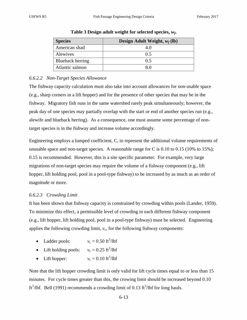
USFWS R5 Fish Passage Engineering Design Criteria February 2017
6-13
Table 3 Design adult weight for selected species, wf.
Species Design Adult Weight, wf (lb)
American shad 4.0
Alewives 0.5
Blueback herring 0.5
Atlantic salmon 8.0
6.6.2.2 Non-Target Species Allowance
The fishway capacity calculation must also take into account allowances for non-usable space
(e.g., sharp corners in a lift hopper) and for the presence of other species that may be in the
fishway. Migratory fish runs in the same watershed rarely peak simultaneously; however, the
peak day of one species may partially overlap with the start or end of another species run (e.g.,
alewife and blueback herring). As a consequence, one must assume some percentage of non-
target species is in the fishway and increase volume accordingly.
Engineering employs a lumped coefficient, C, to represent the additional volume requirements of
unusable space and non-target species. A reasonable range for C is 0.10 to 0.15 (10% to 15%);
0.15 is recommended. However, this is a site specific parameter. For example, very large
migrations of non-target species may require the volume of a fishway component (e.g., lift
hopper, lift holding pool, pool in a pool-type fishway) to be increased by as much as an order of
magnitude or more.
6.6.2.3 Crowding Limit
It has been shown that fishway capacity is constrained by crowding within pools (Lander, 1959).
To minimize this effect, a permissible level of crowding in each different fishway component
(e.g., lift hopper, lift holding pool, pool in a pool-type fishway) must be selected. Engineering
applies the following crowding limit, vc, for the following fishway components:
Ladder pools: vc = 0.50 ft3/lbf
Lift holding pools: vc = 0.25 ft3/lbf
Lift hopper: vc = 0.10 ft3/lbf
Note that the lift hopper crowding limit is only valid for lift cycle times equal to or less than 15
minutes. For cycle times greater than this, the crowing limit should be increased beyond 0.10
ft3/lbf. Bell (1991) recommends a crowding limit of 0.13 ft
3/lbf for long hauls.

USFWS R5 Fish Passage Engineering Design Criteria February 2017
6-14
6.6.2.4 Pass Rate
The pass rate, r, for the fishway must also be estimated to calculate the fishway capacity of a
pool-type fish ladder or fish lift. For pool-type fishways, the pass rate is the rate of ascent, a
measure of how quickly fish of different species can traverse the fishway and is expressed in
pools per minute (Table 4). This parameter reflects both behavioral characteristics and the
swimming speed of the fish. Conceptually, the inverse of r can be regarded as a residence time.
Table 4. Rates of ascent for pool-type fishways
Source Species Rate of ascent, r
(pools/min)
Bell (1991) general 0.250 – 0.400
Clay (1995) chinook salmon 0.200
Elling & Raymond
(1956) general 0.172 – 0.303
USFWS R5
Recommendation
Atlantic salmon 0.250
American shad 0.250
river herring 0.250
For fish lifts, the pass rate, r, is the design cycle time. The cycle time of a lift represents the time
required to perform the steps outlined in Section 7.8. For all but the tallest of lifts, one may
assume a cycle time of 15 minutes or less. Ultimately, the cycle time is a function of the
mechanical design of the various lift elements. Prolonged time in the hopper induces stress in
the fish and should be avoided.
6.6.3 Capacity of Fish Lifts and Pool-Type Fishways
To calculate the required volume for the pools, V, within a pool-type fishway, fish lift holding
pools, and fish lift hoppers, Eq. (12) is used:
𝑉 = 𝑛𝑀𝑤𝑓𝑣𝑐
𝑟[1 + 𝐶] Eq. (12)
For a pool-type fishway, this is required to be less than or equal to the volume of water held in
the pool under normal operating conditions. For a lift holding pool, this is required to be less
than or equal to the volume of water (used by fish) between the downstream edge of the hopper
brail (or leading edge of the hopper) and the closed mechanical crowder. For a lift hopper, this is
required to be less than or equal to the water-retaining volume of the bucket.

USFWS R5 Fish Passage Engineering Design Criteria February 2017
6-15
Other important considerations are below:
The volume of a pool in a pool-type fishway must also consider the effects of hydraulic
parameters such as the energy dissipation factor and streaming versus plunging flow;
Biological capacity of the fish lift holding pool must be equal to or exceed the capacity of
the hopper(s) for proper functioning.
6.6.4 Capacity of Baffled Chute Fishways
Based on research by Slatick (1975), Slatick and Basham (1985), Haro et al. (1999), and
monitoring studies, the USFWS has estimated capacities of Standard Denil ladder fishways
(described in Section 7.6) and Model A Steeppasses (described in Section 7.7). The values
reported in Table 5 assume that there is no overlap in the timing of the migration run for each of
the reported species. In the event of overlapping migrations, the capacity can be expressed in
terms of an equivalent biomass using the design weights presented in Table 3.
Table 5. Fishway capacity for baffled chute fishways
Fishway Type Species Annual Biological Capacity, nT
Standard 4 ft Wide
Denil Ladder
adult American shad 25,000
adult Atlantic salmon 12,000
adult river herring 200,000
Model A Steeppass adult river herring 50,000
adult Atlantic salmon 3,125
6.7 Energy Dissipation in Upstream Fishways
The energy dissipation factor (EDF), introduced in Section 5.4, is a measure of the volumetric
energy dissipation rate (or power dissipation) in a pool, chute or stream reach.
6.7.1 Sizing Step Pools
Eq. (6) in Section 5.4 expresses the potential energy loss (or dissipation) rate per unit length of
fishway. The well-known EDF equation for fishway step pools, illustrated in Figure 6, is derived
from Eq. (6) by: 1) dividing both sides by the mean cross-sectional area of the fishway pool; and
2) recognizing that the term dh/dℓ is equivalent to the (hydraulic) drop per pool over the length
of the pool.

USFWS R5 Fish Passage Engineering Design Criteria February 2017
6-16
𝐸𝐷𝐹 = 𝛾𝑄𝐷
∀𝑃 Eq. (13)
where D is the hydraulic drop per pool in ft, ∀P is the volume of the pool in cubic feet (ft3), 𝛾 is
the unit weight of water in lbf/ft3, and EDF is the energy dissipation factor in ft-lbf/s-ft
3.
Multiplying both sides of Eq. (13) by the pool volume and dividing both sides by the EDF results
in Eq. (14), used for the sizing of fishway step pools:
∀𝑃=𝛾𝑄𝐷
𝐸𝐷𝐹 Eq. (14)
In Eq. (14), the EDF is considered a species-specific criterion. Section 6.7.3 provides
Engineering’s recommended values for selected anadromous fish species.
It is important to note that a proper aspect ratio and depth must be selected in the design of the
step pool. Engineering should be consulted in the design process to ensure that the step pool acts
as both an energy dissipation zone and a resting zone. Further details on the EDF can be found
on Appendix A, Reference Plate 5-2, “Power Dissipation Rates.”
Figure 6: Sizing step pools in a ladder type fishway based on the EDF.
LOSS
POOL VOLUME

USFWS R5 Fish Passage Engineering Design Criteria February 2017
6-17
6.7.2 Sizing Denil Resting Pools
A transferable energy dissipation function, based on energy loss rate from a Standard Denil
resting pool, was developed by Towler et al. (2015):
𝐸𝐷𝐹 = [𝛼1𝑄1
2
2𝐴1−
𝛼2𝑄22
2𝐴2+ 𝑔(𝑧1 − 𝑧2)]
𝑄𝛾
𝐻𝑊𝐿𝑝 Eq. (15)
where H is the mean water surface elevation in the resting pool in ft, W is the width of the Denil
channel in ft, LP is the length of the resting pool in ft, α is the Coriolis coefficient (also referred
to as the kinetic energy correction coefficient), Q is the flow rate in cfs, A is the cross-sectional
area in ft2, g is the gravitational constant in ft/s
2, 𝛾 is the unit weight of water in lbf/ft
3, z is the
elevation of the inlet and outlet sections, and EDF is the energy dissipation factor in ft-lbf/s-ft3.
Shown in Figure 7, the upstream cross section 1 is located at the upstream interface between the
sloped, baffled section and the horizontal pool and the downstream cross section 2 is located at a
point close to the end of the resting pool where conditions are nearly uniform. At cross section
1, the area of flow is given by the following discontinuous function that accounts for the
transition between the v-notched and vertical sections of the baffle:
4sin2
4sin
4sin
2
4sin22
4sin
2
21
cHccH
c
b
cHbcHbc
A Eq. (16)
where b and c are the geometric scaling parameters for the Standard Denil baffle as shown in
Figure 7. For Standard Denil designs, resting pools are generally prismatic, horizontal
extensions of the sloped channel. Thus, the flow area at downstream cross section 2 in Figure 7
is simply the product of H and W. Translating the head above the baffle notch at cross section 1
to the common resting pool floor datum yields:
𝑧1 = 𝐻√2 cos (−𝜋+4 tan−1(𝑆0)
4) Eq. (17)

USFWS R5 Fish Passage Engineering Design Criteria February 2017
6-18
Towler et al. (2015) provides an in-depth analysis of the effect of α on the Eq. (15). When used
in open channel flow calculations, Coriolis values typically range from α = 1 (uniform velocity
distribution) to α = 2. Despite the large range, values above 1.15 rarely occur in regular channels
(Henderson, 1966). However, Denil baffles generate more intense turbulence and irregular
velocity distributions than ordinary open channel flows. To account for this uncertainty,
Engineering recommends the proposed range of acceptable deviations be incorporated into the
design equation. Substituting Eq. (17) into Eq. (15) and replacing α with a ± 5% error bound
results in the following expression for EDF in Standard Denil resting pools:
𝐸𝐷𝐹 = [𝑄
2(
1
𝐴1−
1
𝐻𝑊) + 𝑔𝐻 (√2 cos (
−𝜋+4 tan−1(𝑆0)
4) − 1)]
𝑄𝛾
𝐻𝑊𝐿𝑝 ± 5% Eq. (18)
Recognizing that HWLP is equal to the volume of the pool, ∀𝑃, and dividing each side of Eq.
(18) by the EDF and multiplying each side by ∀𝑃, the generalized equation to size Denil resting
pools is developed:
∀𝑃= [𝑄
2(
1
𝐴1−
1
𝐻𝑊) + 𝑔𝐻 (√2 cos (
−𝜋+4 tan−1(𝑆0)
4) − 1)]
𝑄𝛾
𝐸𝐷𝐹 ± 5% Eq. (19)
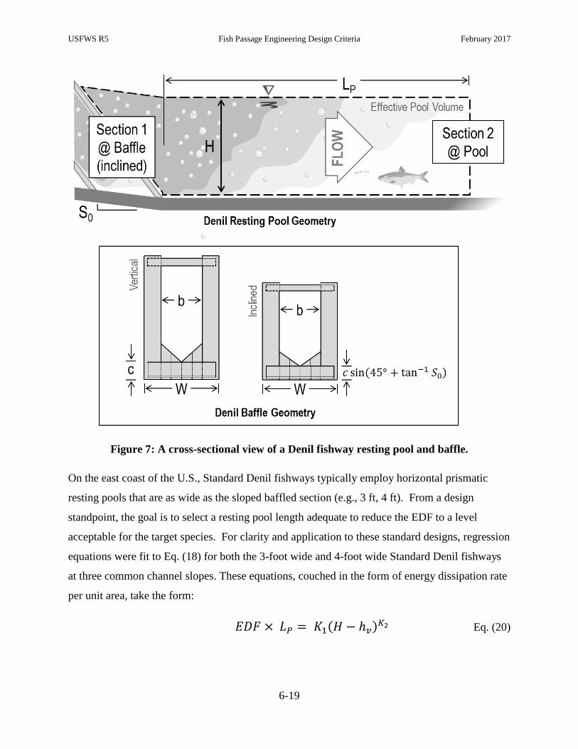
USFWS R5 Fish Passage Engineering Design Criteria February 2017
6-19
Figure 7: A cross-sectional view of a Denil fishway resting pool and baffle.
On the east coast of the U.S., Standard Denil fishways typically employ horizontal prismatic
resting pools that are as wide as the sloped baffled section (e.g., 3 ft, 4 ft). From a design
standpoint, the goal is to select a resting pool length adequate to reduce the EDF to a level
acceptable for the target species. For clarity and application to these standard designs, regression
equations were fit to Eq. (18) for both the 3-foot wide and 4-foot wide Standard Denil fishways
at three common channel slopes. These equations, couched in the form of energy dissipation rate
per unit area, take the form:
𝐸𝐷𝐹 × 𝐿𝑃 = 𝐾1(𝐻 − ℎ𝑣)𝐾2 Eq. (20)
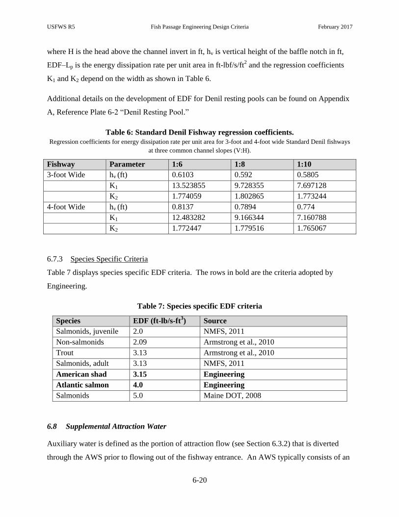
USFWS R5 Fish Passage Engineering Design Criteria February 2017
6-20
where H is the head above the channel invert in ft, hv is vertical height of the baffle notch in ft,
EDF–Lp is the energy dissipation rate per unit area in ft-lbf/s/ft2 and the regression coefficients
K1 and K2 depend on the width as shown in Table 6.
Additional details on the development of EDF for Denil resting pools can be found on Appendix
A, Reference Plate 6-2 “Denil Resting Pool.”
Table 6: Standard Denil Fishway regression coefficients.
Regression coefficients for energy dissipation rate per unit area for 3-foot and 4-foot wide Standard Denil fishways
at three common channel slopes (V:H).
Fishway Parameter 1:6 1:8 1:10
3-foot Wide hv (ft) 0.6103 0.592 0.5805
K1 13.523855 9.728355 7.697128
K2 1.774059 1.802865 1.773244
4-foot Wide hv (ft) 0.8137 0.7894 0.774
K1 12.483282 9.166344 7.160788
K2 1.772447 1.779516 1.765067
6.7.3 Species Specific Criteria
Table 7 displays species specific EDF criteria. The rows in bold are the criteria adopted by
Engineering.
Table 7: Species specific EDF criteria
Species EDF (ft-lb/s-ft3) Source
Salmonids, juvenile 2.0 NMFS, 2011
Non-salmonids 2.09 Armstrong et al., 2010
Trout 3.13 Armstrong et al., 2010
Salmonids, adult 3.13 NMFS, 2011
American shad 3.15 Engineering
Atlantic salmon 4.0 Engineering
Salmonids 5.0 Maine DOT, 2008
6.8 Supplemental Attraction Water
Auxiliary water is defined as the portion of attraction flow (see Section 6.3.2) that is diverted
through the AWS prior to flowing out of the fishway entrance. An AWS typically consists of an

USFWS R5 Fish Passage Engineering Design Criteria February 2017
6-21
intake screen, hydraulic control gate, and energy dissipating pools, baffles, and diffusers. Not
only may the AWS be used to provide additional attraction flow through the fishway entrance,
but it also may be used to add water depth at various locations through the fishway. Figure 3 in
Section 6.4 displays an example of a gravity-fed AWS supplying flow to a fish lift. Attraction
flow is routed through the exit flume via a conduit to the rear AWS chamber and lower AWS
chamber. The flow enters the hopper through a rear diffuser and flow enters the entrance
channel via wall and floor diffusers.
6.8.1 Free Surface (Gravity) AWS
A gravity-fed AWS is a conduit hydraulically connecting the headwater (or forebay) to the
fishway entrance by converting significant potential energy into kinetic energy.
6.8.2 Pressurized AWS
A pressurized AWS is the most common type on the East Coast. The auxiliary water is
transported from the forebay via a closed pipe. The type of valve used within the pipe must be
able to minimize debris entry and any entrained air. Three common valve types are the butterfly,
knife, and bladder valve. The bladder valve is the preferred option as it reduces both debris and
air entering into the system. A bladder valve is made of an inflatable material; when closed, the
bladder valve is filled with air and it effectively seals off the pipe from flow. The knife valve is
effective at reducing air entrainment but can have problems closing when debris is present,
unlike the bladder valve which has been shown to close even around debris. A butterfly valve
should not be used as it is subject to problems with both air entrainment and debris.
6.8.3 Pump AWS
A pump-fed AWS converts mechanical energy into kinetic energy by pumping water from the
tailrace to the fishway.
6.8.4 Intakes
Racks or screens at the flow entrance of an AWS are used to reduce the amount of debris and
prevent fish from entering the system. Engineering recommends:
Juvenile downstream migrants should not be entrained or impinged by the AWS intake
screen (for a gravity-fed system). Screening or other protection measures are assessed by
Engineering on a site-by-site basis.

USFWS R5 Fish Passage Engineering Design Criteria February 2017
6-22
A clear space between the vertical flat bars of 3/8 inch or less is required; this criterion is
based on the exclusion of adult river herring.
Flow velocities should be as close to uniform as possible as the water passes through the
rack or screen.
The gross maximum velocity through the fine trash rack should be less than 1.0 fps as
calculated by Eq. (8).
To facilitate cleaning, the trash rack should be installed at a horizontal to vertical slope of
1:5 or greater and the overall trash rack design should allow for personnel access and
maintain clearance for manual or automated raking.
Occlusion or blockage creates a hydrostatic and hydrodynamic load on a rack. This load
manifests itself, in part, as a head differential across the intake and fine trash rack. The
head differential across a rack should be minimal.
AWS trash racks should be of sufficient structural integrity to minimize deformation.
6.8.5 Diffusers
Both wall and floor diffusers are commonly included in an AWS design. The diffusers provide a
means to reduce excess energy and entrained air as the flow passes from the AWS conduit to
directly within the flow path of the fishway. Wall diffusers consist of vertically-oriented grating
of galvanized steel or aluminum, whereas floor diffusers consist of horizontally-oriented grating.
The following are general recommendations by Engineering pertaining to AWS diffusers:
Diffuser grating panels are typically constructed of 1”x3” or 1”x4” galvanized steel or
aluminum grating. To minimize movement of small fish (e.g., alewife) through a diffuser
panel, the grating should always be installed with the longer dimension (i.e., 3 in. or 4 in.)
aligned to the horizontal plane. However, tighter spacing may be required depending
upon the species present at the site.
The screen size of the AWS intake must be less than or equal to the screen size of the
diffuser screen to prevent fish from being trapped within the AWS.
Vertical (wall) diffusers are preferred over horizontal (floor) diffusers due to the
maintenance, de-watering, and performance issues associated with horizontal diffusers.

USFWS R5 Fish Passage Engineering Design Criteria February 2017
6-23
AWS vertical (wall) diffuser velocities should be less than or equal to 0.5 fps; this
criterion is based on Engineering’s observations that, above 0.5 fps, AWS discharge can
attract and delay fish at the wall diffuser.
Based on the poor performance of high-velocity floor diffusers installed throughout the
region in years past, Engineering has adopted the National Marine Fisheries Service,
Northwest Region horizontal (floor) diffuser velocity criterion of 0.5 fps (NMFS, 2011).
AWS diffusers installed upstream of a hopper in a fish lift may produce acceptable
velocities as high as 1.5 fps.
AWS diffuser velocity calculations should be based on Eq. (8).
The velocity distribution exiting the diffuser should be as close to uniform as possible.
Wall and floor diffusers should be submerged during normal operation of the fishway.
Orientation of the grating should maximize the open area of the diffuser.
All bar edges and surfaces exposed to fish should be rounded or smooth.
Diffuser panels are susceptible to leaves and woody debris. Access for debris removal
from each diffuser should be included within the design.
AWS pits below diffusers must be clear of debris.
6.8.6 Turning Vanes
Turning vanes, illustrated in Figure 3 of Section 6.4, are designed to turn the flow in such a way
that the flow field will quickly approximate a uniform velocity distribution in a desired direction.
These vanes are typically located below horizontal diffusers and direct the flow up through the
diffuser. Criteria regarding spacing and angle of the turning vanes remain under development.
6.8.7 Sizing Dissipation Pools
An energy dissipation pool is an important component of an AWS that is designed for the sole
purpose of dissipating energy from the attraction water (unlike fishway pools which also require
resting zones within the pools). The pool(s) must have sufficient volume to properly dissipate
the incoming kinetic energy. For gravity-fed pools, Engineering recommends a minimum water
volume established by the following formula (similar to Eq. (13)):
𝑉 = 𝛾𝑄𝐻
16.0𝑓𝑡∙𝑙𝑏𝑓
𝑠∙𝑓𝑡3⁄ Eq. (21)
USFWS R5 Fish Passage Engineering Design Criteria February 2017
6-24
where V is the dissipation pool volume in cubic feet, γ is the unit weight of water in pounds per
cubic feet, Q is the flow through the fish ladder in cfs, H is the differential energy head on the
pool in feet, and 16 ft-lbf/s-ft3 is the acceptable maximum EDF (notably greater than the
maximum EDF within fishway pools). Note: in AWS that convey water to the dissipation pool
via closed conduit, the differential energy is significantly reduced by frictional and minor losses
within the pipe; in such systems, H is rarely more than a few feet of head.
6.8.8 Air Entrainment
Generally, air entrainment should be as low as possible within an AWS to reduce the total
amount of entrained air passed on through the fishway. Engineering recommends the following
techniques to reduce aeration within the AWS system:
Proper sizing of the dissipation pools;
Submerging the intake; if this cannot be achieved, Engineering recommends the use of
anti-vortex plates;
Submerge the outlet.
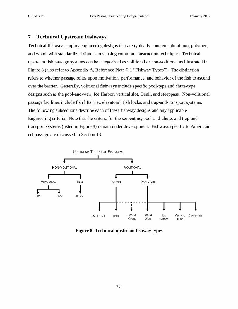
USFWS R5 Fish Passage Engineering Design Criteria February 2017
7-1
7 Technical Upstream Fishways
Technical fishways employ engineering designs that are typically concrete, aluminum, polymer,
and wood, with standardized dimensions, using common construction techniques. Technical
upstream fish passage systems can be categorized as volitional or non-volitional as illustrated in
Figure 8 (also refer to Appendix A, Reference Plate 6-1 “Fishway Types”). The distinction
refers to whether passage relies upon motivation, performance, and behavior of the fish to ascend
over the barrier. Generally, volitional fishways include specific pool-type and chute-type
designs such as the pool-and-weir, Ice Harbor, vertical slot, Denil, and steeppass. Non-volitional
passage facilities include fish lifts (i.e., elevators), fish locks, and trap-and-transport systems.
The following subsections describe each of these fishway designs and any applicable
Engineering criteria. Note that the criteria for the serpentine, pool-and-chute, and trap-and-
transport systems (listed in Figure 8) remain under development. Fishways specific to American
eel passage are discussed in Section 13.
Figure 8: Technical upstream fishway types
VOLITIONAL
CHUTES POOL-TYPETRAP
POOL &
WEIR
SERPENTINEICE
HARBOR
LIFT LOCK
DENILSTEEPPASS VERTICAL
SLOT
TRUCK
MECHANICAL
POOL &
CHUTE
UPSTREAM TECHNICAL FISHWAYS
NON-VOLITIONAL
USFWS R5 Fish Passage Engineering Design Criteria February 2017
7-2
7.1 Pool-and-Weir Fishways
Pool-and-weir fishways are characterized by a series of pools separated by overflow weirs that
break the total head into discrete, passable increments.
7.1.1 Slope
The slope of a pool-and-weir fishway is calculated by dividing the (exterior) length of the pool
by the hydraulic drop per pool.
The slope of a pool-and-weir fishway should be less than or equal to 10%.
Pool-and-weir fishways are designed for “uniform-in-the-mean” conditions (Towler et
al., 2015). That is, each successive pool maintains the same hydraulic characteristics at
the inlet and outlet. Therefore, the slope of the fishway is approximately equal to the
friction slope (slope of the energy grade line).
7.1.2 Pool Geometry
Resting pools create hydraulic conditions that promote fish recovery from energy demanding
high speed swimming before ascending the next step pool section.
Typically, a resting pool is rectangular in shape. The specific geometry is dependent
upon velocity, flow, depth, streaming/plunging conditions, and EDF criteria. In addition,
a biological capacity requirement must be met.
For large streams or rivers, biological capacity and EDF criteria often require pools 8‐feet
long or greater.
7.1.3 Weirs
The design of the weir must take into account both the flow depth and the velocity of the jet over
the weir crest in relation to the size of the target species and any ability to leap over obstructions.
To safely pass fish, weirs should be designed to provide a minimum of two body depths
of flow depth over the weir crest with a minimum submergence of the crest that promotes
streaming flow conditions.
The velocity of the jet over the weir crest must be low enough to permit passage of all
target fish species at the site. The velocity of the jet is proportional to the square root of
the hydraulic head on the crest. Thus, knowledge of the target fish species swimming

USFWS R5 Fish Passage Engineering Design Criteria February 2017
7-3
capabilities is required to determine the maximum flow depth over the weir in which
passage can occur.
The weir-to-weir alignment of the low flow notch must be designed to reduce momentum
loss in the jet through the interstitial pool.
7.1.4 Hydraulic Drop
The hydraulic drop from pool to pool is a function of several factors, including the water surface
elevation of the downstream pool, flow rate and velocity over the weir, and weir width. The
maximum hydraulic drop between pools should be approximately 1.0 foot; however, actual drop
is determined by ensuring the fishway meets all other hydraulic criteria including velocity and
streaming flow.
7.1.5 Orifices
Submerged orifices are often included as an alternate route of passage (for salmonids) and may
also promote streaming flow under threshold conditions.
Orifices can be aligned on one side or alternating side-to-side.
Often built with a deflecting baffle design immediately downstream to redirect the flow
towards the center of the pool.
The dimensions of orifices should be sized to maintain streaming flow and adequate fish
passage conditions (e.g., velocities, width).
The top and sides should be chamfered 0.75 inches on the upstream side and chamfered
1.5 inches on the downstream side of the orifice.
The orifices must be void of debris at all times during the migration season. Blockages
can create high velocities at the orifice and other complex hydraulic conditions which can
reduce the efficacy of the fishway.
7.1.6 Turning Pools
Turning pools are locations within the fishway where bends are required. These pools are often
curved in shape or rectangular with chamfered walls. This shape differs from linear resting pools
and, consequently, can create much more complex hydraulic conditions. Turning pools often
also act as a resting pool.

USFWS R5 Fish Passage Engineering Design Criteria February 2017
7-4
The design of the fishway should limit the number of turning pools to a feasible
minimum.
The hydraulic conditions within a turning pool must be designed to elicit a rheotactic
response from the upstream migrating fish.
The flow field should be nearly uniform throughout the turning pool.
Turning pools should be designed to minimize flow separation and turbulence. The walls
should be chamfered (ideally circular).
The upstream pool width should be maintained throughout the entirety of the bend.
Ideally, turning pools should have bends of 90 degrees or less. Greater than 90 degrees
increases risk for poor hydraulic conditions and can cause confusion to fish, especially
American shad, as they attempt to migrate upstream through the fishway.
For turning pools which require a bend greater than 90 degrees, a weir should be placed
at the midpoint of the pool creating a jet of water designed to motivate fish to continue
ascending the fishway.
7.2 Ice Harbor Fishways
An Ice Harbor fishway is a modified pool-and-weir ladder that has two weir crests separated by a
non-overflow central baffle and two submerged orifices centered below the crests.
The Appendix A, Reference Plate 7-1 “Ice Harbor Fishway” illustrates design schematic and
provides a list of standard dimensions. Figure 9 displays the Ice Harbor standard dimension
parameters, pertinent geometric ratios, and design criteria.

USFWS R5 Fish Passage Engineering Design Criteria February 2017
7-5
Figure 9: Ice Harbor fishway standard dimensions.
Ice Harbor fishway standard dimensions; where BW is the overflow weir crest width, BB is the non-overflow baffle
width, A0 is the area of the orifice opening, S0 is the floor slope, L is the pool length, W is the pool width, P is the
overflow weir crest height, tW is the overflow weir crest thickness, and ɛ is the distance from the center of the orifice
to the side wall.
7.2.1 Slope
The slope of a pool-type fishway is calculated by dividing the length of the pool by the hydraulic
drop per pool.
The slope of an Ice Harbor fishway should be less than or equal to 10%.
Ice Harbor fishways are designed for “uniform-in-the-mean” conditions (Towler et al.,
2015). That is, each successive pool maintains the same hydraulic characteristics at the
inlet and outlet. Therefore, the slope of the fishway is approximately equal to the friction
slope (slope of the energy grade line).

USFWS R5 Fish Passage Engineering Design Criteria February 2017
7-6
7.2.2 Pool & Central Baffle Geometry
The pool width, W, typically ranges from 10 to 25 feet. The pool length, L, must be
greater than or equal to 9 feet. However, the specific pool geometry is dependent upon
velocity, flow, depth, streaming/plunging conditions, and EDF criteria.
The difference in height between the top of the non-overflow central baffle and the weir
crest is typically 2 feet.
Typically, the width of the central baffle, BB, is 37.5% of the pool width, W.
The central baffle is equipped with flow stabilizers which take the form of stub walls
facing upstream at each end. Typically, the length of the two stub walls is 1.5 feet.
7.2.3 Weirs
An Ice Harbor fishway has two symmetrical weir crests, separated by a central baffle.
The width of each weir crest, BW, is typically 31.25% of the pool width, W. This results
in an effective weir width of 62.5% of W.
7.2.4 Orifices
Similar to weirs, the Ice Harbor fishway has two symmetrical orifices, rectangular in shape,
below the weir crests. The bottom of the orifice is the fishway floor. The two orifices provide
an alternate route for upstream movement through the structure, although most fish swim over
the weirs.
The size of the orifice opening typically varies from 12 in. x 12 in. for a 10 foot wide
pool to 18 in. x 18 in. for a 25 foot wide pool.
7.2.5 Turning Pools
Refer to Section 7.1.6, Turning Pools of Pool-and-Weir Fishways.
7.3 Alternating Ice Harbors
The Alternating Ice Harbor is a low flow variant of the Ice Harbor fishway. In each pool, one of
the weirs and one of the orifices is blocked, in alternating arrangement. This effectively reduces
the flow, increasing the relative volume available for energy dissipation.
USFWS R5 Fish Passage Engineering Design Criteria February 2017
7-7
Alternating Ice Harbors are not designed as such; they are post-construction modifications to
(poorly performing) Ice Harbor fishways.
7.3.1 Slope
The slope of a pool-type fishway is calculated by dividing the length of the pool by the hydraulic
drop per pool.
The slope of an Alternating Ice Harbor fishway should be less than or equal to 10%.
Alternating Ice Harbor fishways are designed for “uniform-in-the-mean” conditions
(Towler et al., 2015). That is, each successive pool maintains the same hydraulic
characteristics at the inlet and outlet. Therefore, the slope of the fishway will
approximate the friction slope (slope of the energy grade line).
7.3.2 Pool & Central Baffle Geometry
Criteria in development.
7.3.3 Weir and Weir Arrangement
Criteria in development.
7.3.4 Orifice and Orifice Arrangement
Criteria in development.
7.3.5 Turning Pools
Criteria in development.
7.4 Half Ice Harbor Fishways
The Half Ice Harbor is a low flow variant of the Ice Harbor fishway. The geometry of a Half Ice
Harbor is, as the name implies, equivalent to a lateral section of the full Ice Harbor cut along a
plane of symmetry defined by its central axis. Accordingly, the low flow fishway consists of one
weir crest, one orifice, and a non-overflow baffle between fishway pools.
Engineering’s experience is that it is challenging to maintain streaming flow conditions in a Half
Ice Harbor fishway. For this reason, Half Ice Harbor fishways are not recommended for
American shad.

USFWS R5 Fish Passage Engineering Design Criteria February 2017
7-8
7.4.1 Slope
The slope of a pool-type fishway is calculated by dividing the length of the pool by the hydraulic
drop per pool.
The slope of a Half Ice Harbor fishway should be less than or equal to 10%.
Half Ice Harbor fishways are designed for “uniform-in-the-mean” conditions (Towler et
al., 2015). That is, each successive pool maintains the same hydraulic characteristics at
the inlet and outlet. Therefore, the slope of the fishway will approximate the friction
slope (slope of the energy grade line). Engineering’s experience is that the typical
geometry of the Half Ice Harbor (e.g., 1 foot drop, 10% slope) does not adequately
dissipate energy. As a result, high approach velocities at the weir often inhibit the ascent
of American shad and river herring.
7.4.2 Pool & Central Baffle Geometry
Criteria in development.
7.4.3 Weir and Weir Arrangement
Criteria in development.
7.4.4 Orifice and Orifice Arrangement
To reduce the turbulence and air entrainment in Half Ice Harbors, Engineering recommends
blocking the orifice. American shad, river herring, and American eel do not generally pass
through submerged orifices. Closing the orifice significantly reduces fishway flow, and
consequently the EDF.
7.4.5 Turning Pools
Refer to Section 7.1.6.
7.5 Vertical Slot Fishways
A vertical slot fishway is a pool-type fish ladder characterized by a rectangular channel with a
sloping floor in which a series of regularly spaced baffles separate the pools. Water flows from
pool to pool via a vertical slot at each baffle. These designs are applicable to medium head dams
and, unlike pool-and-weir fishways, may accommodate large fluctuations in headwater and
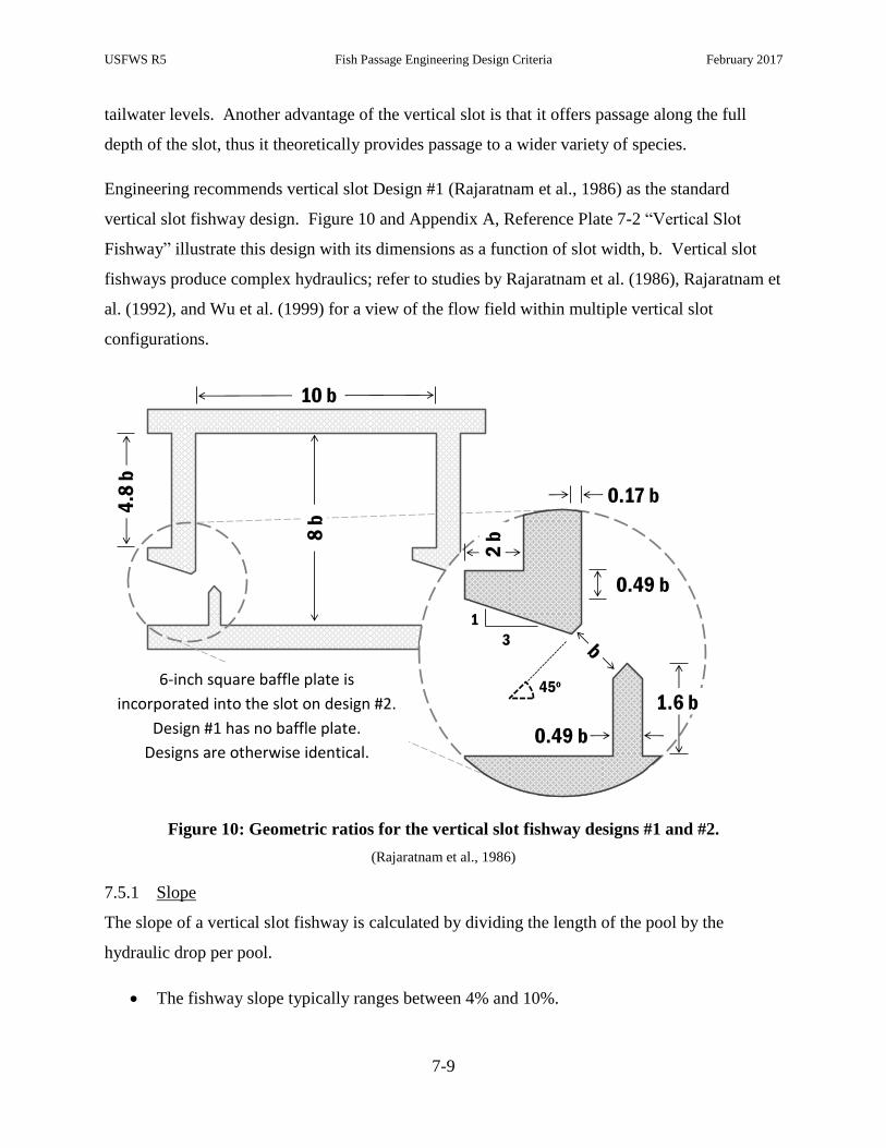
USFWS R5 Fish Passage Engineering Design Criteria February 2017
7-9
tailwater levels. Another advantage of the vertical slot is that it offers passage along the full
depth of the slot, thus it theoretically provides passage to a wider variety of species.
Engineering recommends vertical slot Design #1 (Rajaratnam et al., 1986) as the standard
vertical slot fishway design. Figure 10 and Appendix A, Reference Plate 7-2 “Vertical Slot
Fishway” illustrate this design with its dimensions as a function of slot width, b. Vertical slot
fishways produce complex hydraulics; refer to studies by Rajaratnam et al. (1986), Rajaratnam et
al. (1992), and Wu et al. (1999) for a view of the flow field within multiple vertical slot
configurations.
Figure 10: Geometric ratios for the vertical slot fishway designs #1 and #2.
(Rajaratnam et al., 1986)
7.5.1 Slope
The slope of a vertical slot fishway is calculated by dividing the length of the pool by the
hydraulic drop per pool.
The fishway slope typically ranges between 4% and 10%.
10 b
8 b
4.8
b
3
1
1.6 b
0.17 b
0.49 b
2 b
0.49 b
45o6-inch square baffle plate is
incorporated into the slot on design #2.
Design #1 has no baffle plate.
Designs are otherwise identical.
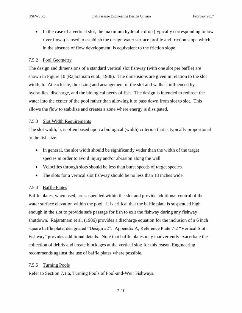
USFWS R5 Fish Passage Engineering Design Criteria February 2017
7-10
In the case of a vertical slot, the maximum hydraulic drop (typically corresponding to low
river flows) is used to establish the design water surface profile and friction slope which,
in the absence of flow development, is equivalent to the friction slope.
7.5.2 Pool Geometry
The design and dimensions of a standard vertical slot fishway (with one slot per baffle) are
shown in Figure 10 (Rajaratnam et al., 1986). The dimensions are given in relation to the slot
width, b. At each site, the sizing and arrangement of the slot and walls is influenced by
hydraulics, discharge, and the biological needs of fish. The design is intended to redirect the
water into the center of the pool rather than allowing it to pass down from slot to slot. This
allows the flow to stabilize and creates a zone where energy is dissipated.
7.5.3 Slot Width Requirements
The slot width, b, is often based upon a biological (width) criterion that is typically proportional
to the fish size.
In general, the slot width should be significantly wider than the width of the target
species in order to avoid injury and/or abrasion along the wall.
Velocities through slots should be less than burst speeds of target species.
The slots for a vertical slot fishway should be no less than 18 inches wide.
7.5.4 Baffle Plates
Baffle plates, when used, are suspended within the slot and provide additional control of the
water surface elevation within the pool. It is critical that the baffle plate is suspended high
enough in the slot to provide safe passage for fish to exit the fishway during any fishway
shutdown. Rajaratnam et al. (1986) provides a discharge equation for the inclusion of a 6 inch
square baffle plate, designated “Design #2”. Appendix A, Reference Plate 7-2 “Vertical Slot
Fishway” provides additional details. Note that baffle plates may inadvertently exacerbate the
collection of debris and create blockages at the vertical slot; for this reason Engineering
recommends against the use of baffle plates where possible.
7.5.5 Turning Pools
Refer to Section 7.1.6, Turning Pools of Pool-and-Weir Fishways.

USFWS R5 Fish Passage Engineering Design Criteria February 2017
7-11
7.6 Standard Denil Fishways
Denil designs are a family of baffled-chute ladders that utilize roughness elements (i.e., baffles)
to dissipate the kinetic energy of water moving through a flume to create a low velocity zone of
passage for migratory fish. The baffles turn a portion of the flow to oppose the main current in
the flume. This change in inertia results in a decrease in flume velocity but also generates
considerable turbulence that can reduce passage efficiency. Though limited in biological
capacity, Denil fishways have demonstrated an efficacy in the passage of salmonids, alosines,
and other species at relatively steep slopes.
A Standard Denil, displayed in Figure 11, is typically composed of a 2-4 feet wide prismatic
concrete, steel or wood channel. The Denil fishway can operate over a moderate range of
impoundment water level fluctuation. A minimum flow depth of 2 feet or two body depths
(whichever is greater) should be maintained throughout the entirety of the fishway. The
maximum operating water depth must remain 3.0 inches below any cross-support members (on
the upper portion of the baffles).
Figure 11: A Standard Denil fishway illustration.
ENTRANCE
TURNING POOL
BAFFLES
EXIT NON-OVERFLOW
SECTION
DAM
USFWS R5 Fish Passage Engineering Design Criteria February 2017
7-12
7.6.1 Entrance
At all times, the flow depth at the entrance (measured above the channel floor, gate lip, or
weir boards) must be at least 2 feet or two body depths (whichever is greater). In
practice, this typically requires a fishway be designed to maintain this depth during low
operating TW (i.e., tailwater elevation at the low design flow).
Fully submerged stop-logs at the most downstream point of the fishway (the actual
entrance) should be used to maintain depth in the entrance.
Entrances, particularly those without significant flow contributions from an AWS, should
be laterally contracted at the entrance to promote a strong entrance jet. The contracted
entrance should be 62.5% (5/8th) of the channel width.
7.6.2 Slope
Recommended slopes for a Denil vary by target species.
The slope of a Denil designed to pass only salmonids can be up to 16.7% (1:6).
The slope of a Denil designed to pass American shad should not be steeper than 12.5%
(1:8); a slope of 10% (1:10) is preferred.
Ignoring the effect of flow development in the upper reach of baffled chutes and
conceptualizing the energy-dissipating baffles in steeppasses and Standard Denil
fishways as roughness elements, one may treat flow in baffled chutes as essentially
uniform between any two sections. Therefore, the slope of the fishway will approximate
the friction slope (slope of the energy grade line).
7.6.3 Channel Width
Similar to the fishway slope, recommended widths for Denils vary by target species.
Standard Denil ladders designed to pass only salmonids are typically 3-feet wide.
Standard Denil ladders designed to pass American shad should have a width of 4 feet.
7.6.4 Baffle Geometry and Spacing
Figure 12 and Appendix A, Reference Plate 7-3 “Standard Denil Geometry” display the baffle
geometry and the horizontal (longitudinal) spacing of baffles in the channel.
Baffles are typically set at a 45 degree angle to the sloped floor.

USFWS R5 Fish Passage Engineering Design Criteria February 2017
7-13
The baffle height is typically 1 foot greater than the high design flow water surface
elevation.
Figure 12: A Standard Denil baffle geometry.
A Standard Denil baffle geometry, where W is the Denil channel width (typically the inside width of the concrete
channel) and S is the horizontal (longitudinal) spacing of baffles in channel.
7.6.5 Baffle Material
The baffles are typically built from dimensional lumber (e.g., 2 x 6, 2 x 8). The lumber is often
assembled with stainless carriage bolts. A top cross beam lends support and should remain
above the water surface through the operational range. Acceptable lumber material includes oak,
white pine, ash, cypress and marine-grade high-density polyethylene (HDPE).
7.6.6 Turning and Resting Pools
Unlike pool-type fishways, baffled-chute designs do not necessarily incorporate resting pools for
migrants ascending the ladder. Therefore, Denil fishways must be designed with resting pools at
appropriate intervals. Resting pools can be placed between two chute sections or incorporated as
turning pools at switchbacks or other directional changes.
USFWS R5 Fish Passage Engineering Design Criteria February 2017
7-14
A resting pool should be incorporated every 6 to 9 feet of vertical rise.
Resting pool volumes must adhere to volume requirements specified in Section 6.7.1.
Refer to Section 6.7.2 for the sizing of Standard Denil resting pools.
Refer to Section 7.1.6 for more recommendations regarding turning pools.
7.6.7 Operating Range
The operating range of a Denil is bracketed by the lowest and highest depths over which the
fishway may safely pass fish. These depths are measured from the bottom of the exit channel,
the effective hydraulic control of a Denil. Ideally, the lowest and highest depths correlate to
headpond elevations at the low design flow and high design flow, respectively. Practically, this
range is influenced, and often limited, by the width of the channel, the height of the baffle, and
size and swimming ability of the target species. If operating levels cannot be set to encompass
the entire design flow range, set the exit channel bottom to optimize passage at the site.
Appendix A, Reference Plate 7-4, “Standard Denil Operating Range” provides criteria for the
operating range of a Standard Denil fishway. The low operating (water) level was based on
providing two body depths of water in the rectangular section of the Denil baffle. A nominal
adult body depth of 4 inches was used for river herring; 6 inches for American shad; and 8 inches
for Atlantic Salmon. The horizontal projection of C, as shown of Figure 12, was used to identify
the starting elevation of the rectangular section of 5 to 8 foot long baffles. The high operating
level was based on the horizontal projection of the supporting cross member (located
approximately 6 inches below the projected top of all baffles).
It is important to note that the high operating water level may be further limited by the
swimming capability of the target species. For example, the high operating level in a 4-foot
wide, 8-foot long baffle set in a Denil fishway at a 1:8 slope is approximately 5.75 feet above the
exit channel bottom; however, the average velocity in the baffle may exceed the swimming
ability of river herring (e.g., 4 ft/s) when the water level reaches 4.7 feet above the exit channel
bottom. Limitations due to river herring (and weaker resident fish) swimming capabilities
typically occur when the depth of flow exceeds 4.5 feet in any 3 or 4-foot wide Denil built at a
1:8 or 1:10 slope. Other combinations of baffle width, channel slope and target species should
be considered in the design process, as appropriate.
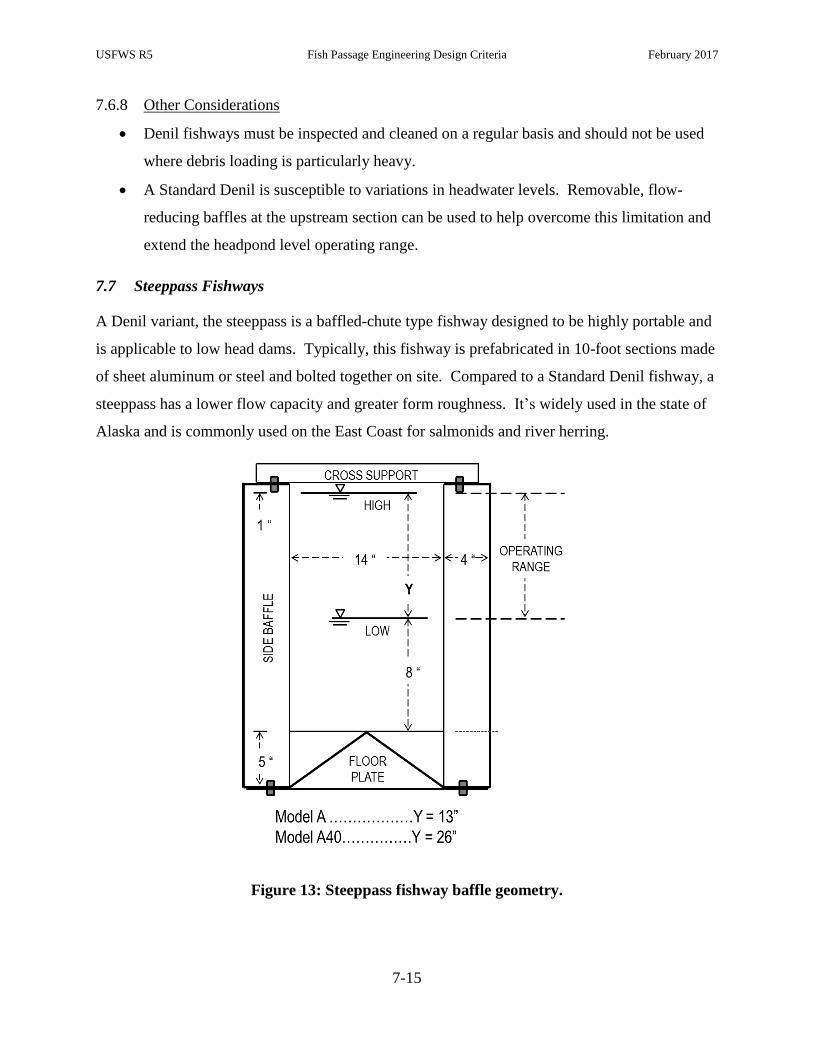
USFWS R5 Fish Passage Engineering Design Criteria February 2017
7-15
7.6.8 Other Considerations
Denil fishways must be inspected and cleaned on a regular basis and should not be used
where debris loading is particularly heavy.
A Standard Denil is susceptible to variations in headwater levels. Removable, flow-
reducing baffles at the upstream section can be used to help overcome this limitation and
extend the headpond level operating range.
7.7 Steeppass Fishways
A Denil variant, the steeppass is a baffled-chute type fishway designed to be highly portable and
is applicable to low head dams. Typically, this fishway is prefabricated in 10-foot sections made
of sheet aluminum or steel and bolted together on site. Compared to a Standard Denil fishway, a
steeppass has a lower flow capacity and greater form roughness. It’s widely used in the state of
Alaska and is commonly used on the East Coast for salmonids and river herring.
Figure 13: Steeppass fishway baffle geometry.

USFWS R5 Fish Passage Engineering Design Criteria February 2017
7-16
7.7.1 Slope
The standard slope of a steeppass fishway ranges between 10 and 33%; Engineering
recommends steeppasses be installed at a slope of 20% (1V:5H) or milder.
NMFS (2011) recommends the slope be less than or equal to 28%.
Larinier et al. (2002) recommends a slope of 23-33%.
NRCS (2007) recommends a slope of up to 35%.
Ignoring the effect of flow development in the upper reach of baffled chutes and conceptualizing
the energy-dissipating baffles in steeppasses and Denil fishways as roughness elements, one may
treat flow in baffled chutes as essentially uniform between any two sections. Therefore, the
slope of the fishway will be equal to the friction slope (slope of the energy grade line).
7.7.2 Model A Steeppass
A Model A Steeppass (refer to Figure 13 and Appendix A, Reference Plate 7-5 “Model A
Steeppass”) is a 21‐inch wide, 27‐inch tall, baffled aluminum (or steel) channel. The effective
zone of passage is the area between the side baffles, above the top of the floor “V” plate (8
inches below the minimum water level for the operating range), and 1 inch below the cross
struts. As depicted in Appendix A, Reference Plate 7-5 “Model A Steeppass,” a Model A
Steeppass can only accommodate a 10-inch fluctuation in headwater level.
7.7.3 Model A40 Steeppass
The Model A40 Steeppass is a 40‐inch tall, deepened version of the Model A Steeppass.
Consequently, the Model A40 Steeppass can accommodate a 23 inch fluctuation in headwater
level, 13 inches greater than the Model A Steeppass. The Model A40 ladder is also known as a
“deepened steeppass”.
7.7.4 Turning and Resting Pools
Similar to Denil ladders, a steeppass fishway does not necessarily incorporate resting pools. In
most cases, the length of the steeppass is short enough such that no resting pools are required. A
resting pool should be incorporated every 6 to 9 feet of vertical rise and be a minimum of 6 feet
long.

USFWS R5 Fish Passage Engineering Design Criteria February 2017
7-17
7.7.5 Other Considerations
A steeppass fishway is limited by its low flow capacity. As a result, steeppasses are only
applicable to small (coastal) watersheds; the Model A is limited to locations with a
drainage area of 20 square miles or less, whereas the Model A40 is limited to locations
with a drainage area of 30 square miles or less.
The direction of the V-plate within the baffle is critical to the functioning of a steeppass
fishway. The apex of the V must be pointed upstream.
In many cases an entrance structure (concrete, wood, aluminum) is used to maintain
adequate flow conditions within the steeppass and at the entrance.
A critical component of a properly operating steeppass is that the invert of the entrance
be submerged a minimum of 13 inches at low tailwater.
7.8 Fish Lifts
Fish lifts or elevators, illustrated in Figure 14 (alternative views are in Figures 2, 3, and 5), are
non‐volitional upstream fishways that are comprised of numerous mechanical, hydraulic, and
electrical components. Generally, fish lifts have a smaller footprint than large volitional passage
designs. The cycle of a fish lift consists of the following sequences:
1. Fishing: Fish, attracted to the fishway entrance, enter the fishway through the entrance
structure (e.g., gate). Fish swim upstream within the fishway to the holding pool through
a V-gate designed to retain the fish within the pool.
2. Crowding: The V-gate (or similar mechanism) is then used to mechanically crowd the
fish above the hopper.
3. Lifting: Fish are lifted within the hopper to the exit channel or impoundment.
4. Releasing: Fish are released from the hopper to the exit channel.
5. Returning: The hopper, empty of fish, is returned to the fishing position.
Further information on fish lifts is provided in the Appendix A, Reference Plate 7-6 “Fish Lift
Velocities” and Reference Plate 7-7 “Fish Lift Sequence.”
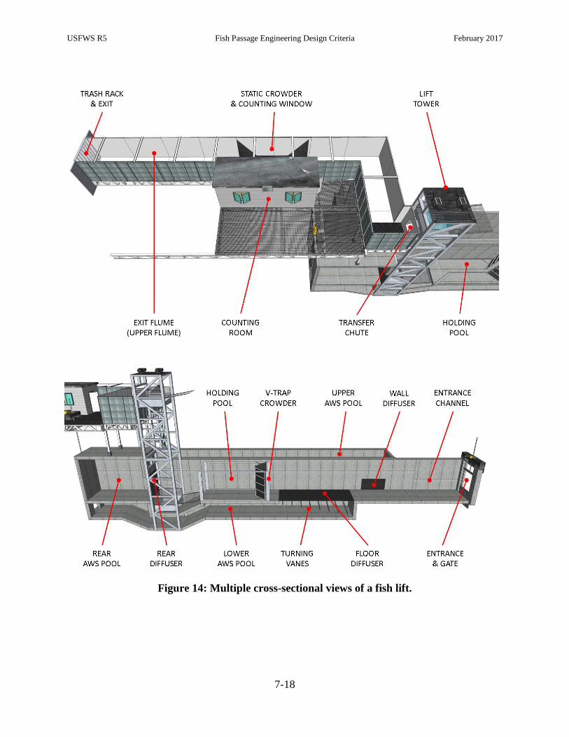
USFWS R5 Fish Passage Engineering Design Criteria February 2017
7-18
Figure 14: Multiple cross-sectional views of a fish lift.
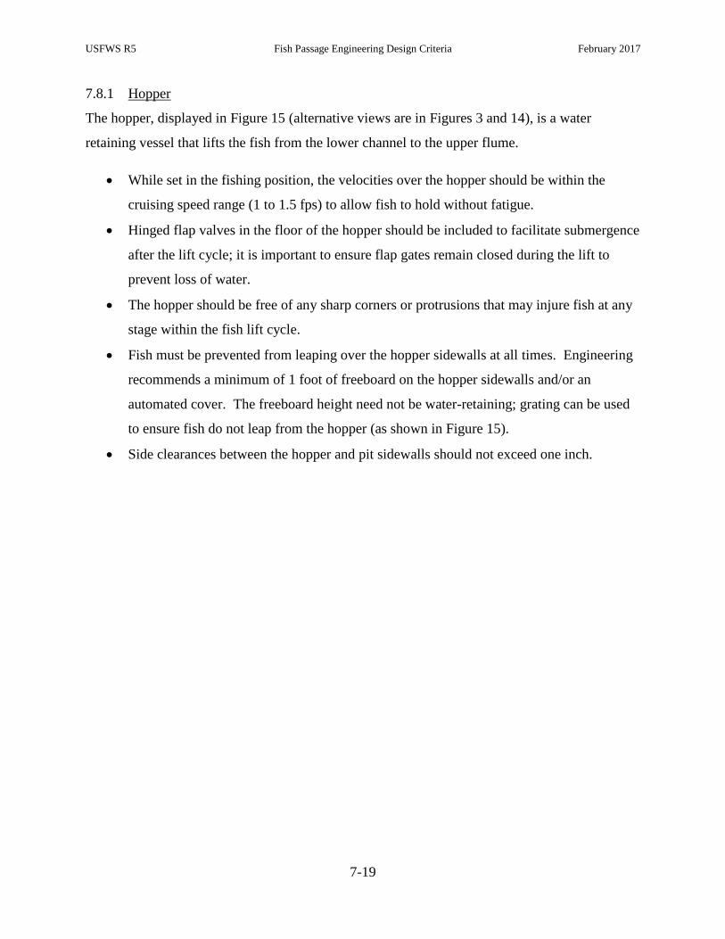
USFWS R5 Fish Passage Engineering Design Criteria February 2017
7-19
7.8.1 Hopper
The hopper, displayed in Figure 15 (alternative views are in Figures 3 and 14), is a water
retaining vessel that lifts the fish from the lower channel to the upper flume.
While set in the fishing position, the velocities over the hopper should be within the
cruising speed range (1 to 1.5 fps) to allow fish to hold without fatigue.
Hinged flap valves in the floor of the hopper should be included to facilitate submergence
after the lift cycle; it is important to ensure flap gates remain closed during the lift to
prevent loss of water.
The hopper should be free of any sharp corners or protrusions that may injure fish at any
stage within the fish lift cycle.
Fish must be prevented from leaping over the hopper sidewalls at all times. Engineering
recommends a minimum of 1 foot of freeboard on the hopper sidewalls and/or an
automated cover. The freeboard height need not be water-retaining; grating can be used
to ensure fish do not leap from the hopper (as shown in Figure 15).
Side clearances between the hopper and pit sidewalls should not exceed one inch.

USFWS R5 Fish Passage Engineering Design Criteria February 2017
7-20
Figure 15: Illustration of fish lift components.
Fish lift components including a fish lift hopper, mechanical crowder track, holding pool, and V-trap mechanical
crowder in the fishing position.
7.8.2 Holding Pool
A fish lift’s holding pool, illustrated in Figure 15 (alternative views are in Figures 3 and 14), is a
section in the lower channel that is downstream of the hopper and bound by the (open)
mechanical crowder. The purpose of the holding pool is to retain migrants prior to crowding
them into the hopper.
Section 6.6.3 provides guidance on the proper sizing of holding pools.
The velocities within the holding pool should be within the cruising speed range (1 to 1.5
fps for most East Coast anadromous species) to allow fish to hold without fatigue.
7.8.3 Crowder
A crowder is a mechanical device designed to move fish from the holding pool into the hopper
prior to the lifting sequence. The components of a crowder typically include: 1) a trolley
supported V-gate screen; 2) a hoist; and 3) the supporting crowder track on which the V-gate is
moved from the entrance of the holding pool to immediately downstream of the hopper and
brailling system. In the fishing position (i.e., collecting fish from the entrance), the V-gate is
USFWS R5 Fish Passage Engineering Design Criteria February 2017
7-21
parked at the entrance of the holding pool (as shown in Figure 15) and acts to discourage fish
within the holding pool from moving back out into the entrance channel. In this position, the V-
gate is open 6 to 24 inches, although specific settings should be adjusted in response to fish
behavior and implemented through adaptive management. Prior to lifting, the V-gate is closed
and moves linearly toward the holding pool, effectively crowding the fish into the space above
the submerged hopper.
Alternatively, the mechanical V-gate crowder can be replaced by an angled screen (or floor brail)
that extends from the downstream end of the hopper to a static V-gate. The hopper and angled
screen are then lifted simultaneously, forcing fish into the hopper.
The floor screen (brail) from the hopper to the V-gate is typically set at an angle of 10 to
20 degrees.
The dimensions of the screens used in the V-gate and floor brail must be sized to retain
fish in the holding pool and avoid injury.
In the case of a rectangular mesh screen, the openings should be sized at a ratio of 3:1
(H:V) to reduce the chance of fish injury.
The screens must be clear of debris at all times during operation, although the AWS trash
racks should prevent most debris from entering the fishway.
The V-gate should extend at least 12 inches above the high fish passage design flow
elevation.
A typical V-gate installation has a gap between the gate and the location in which it
hinges to the inside wall of the entrance flume. Rubber seals should be installed to
eliminate a potential avenue around the V-gate and reduce the risk of injury.
7.8.4 Exit Flume
The exit flume is the steel or concrete channel connecting the hopper discharge chute and the
fishway exit.
Flow velocities in the exit channel should be low enough to prevent fatigue, yet high
enough to motivate fish to move out of the channel and into the impoundment.
Engineering recommends velocities are maintained in the range of 1.0 to 1.5 fps in this
channel.

USFWS R5 Fish Passage Engineering Design Criteria February 2017
7-22
It is important to note that velocity in the exit channel is typically created by a screened
intake to a return pipe which conveys the water to the lower fishway and contributes to
the attraction flow. Engineering recommends that this return pipe be outfitted with a gate
or bladder valve; the valve can be used to adjust the exit flume velocity to optimize
movement of fish through the exit.
Where possible, the exit flume design should avoid sudden transitions in lighting or
hydraulics that could induce an adverse behavioral reaction in fish leaving the fishway.
7.8.5 Cycle Time
Lift cycle time is defined in Section 6.6.2.4. Refer to Appendix A, Reference Plate 7-7 “Fish
Lift Sequence” for a detailed view of the standard fish lift cycle sequence of events.
7.8.6 Hopper to Flume Transfer
The hopper discharge chute (i.e., the chute through which fish are emptied into the exit channel)
should be large enough to empty the hopper rapidly (about 15 to 20 seconds). The discharge
chute, shown in Figure 16, should also have rounded corners or a bell mouth to provide a gradual
hydraulic transition to promote fish movement from the hopper to the exit channel. The transfer
must provide safe passage into the receiving water of the exit flume. Engineering prefers that the
fish always remain in an adequate depth of water during the transfer. In the event that trapping is
required, the hopper may be configured with a secondary discharge to trapping and holding
facilities.
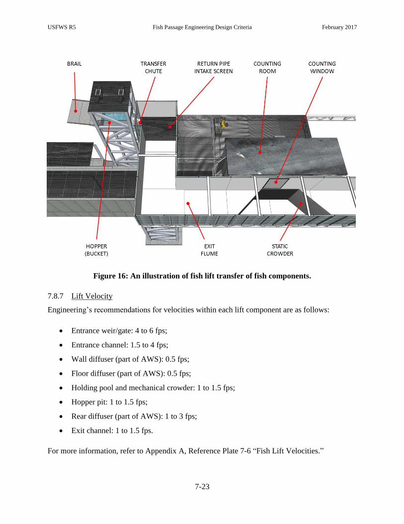
USFWS R5 Fish Passage Engineering Design Criteria February 2017
7-23
Figure 16: An illustration of fish lift transfer of fish components.
7.8.7 Lift Velocity
Engineering’s recommendations for velocities within each lift component are as follows:
Entrance weir/gate: 4 to 6 fps;
Entrance channel: 1.5 to 4 fps;
Wall diffuser (part of AWS): 0.5 fps;
Floor diffuser (part of AWS): 0.5 fps;
Holding pool and mechanical crowder: 1 to 1.5 fps;
Hopper pit: 1 to 1.5 fps;
Rear diffuser (part of AWS): 1 to 3 fps;
Exit channel: 1 to 1.5 fps.
For more information, refer to Appendix A, Reference Plate 7-6 “Fish Lift Velocities.”

USFWS R5 Fish Passage Engineering Design Criteria February 2017
7-24
7.8.8 Other Considerations
An entrance attraction jet (combined fishway and AWS discharge) is created by
acceleration due to entrance (lift) gate operations; the jet typically results in a 0.5 – 2.0
foot hydraulic drop into the TW. The drop must not impede fish passage and should
produce streaming flow. Actual site-specific settings should be based on total attraction
flow, tailwater fluctuations, fish behavior and attraction efficiency.
Flood walls and other lift components should be designed to protect against a 50-year
flood event.
Flow in the entrance channel, downstream of the diffusers, should be streamlined and
relatively free of eddies and aeration.
Diffuser velocities are maximum point velocities; localized upwelling and aeration from
the AWS should be minimal.
Water depth in the lower flume should be greater than 4 feet at all times.
Flow above hopper and in holding pool should be free of aeration (i.e., visible bubbles).
As much AWS flow as possible should be discharged behind the hopper through the rear
diffuser, without exceeding maximum water velocity at the hopper pit or the holding
pool.
AWS dissipaters should be designed to remove excess energy from flow.
7.9 Fish Locks
A fish lock is a non-volitional fishway consisting of a columnar structure that, when filled with
water, acts as a passage route for migrating fish. The design principle of the columnar structure
within a fish lock is similar to the hopper and lift tower within a fish lift. Controllable gates at
the headwater and tailwater openings are used to fill the structure with water. Locks are
characterized by particularly long cycle times. Fish locks are rare on the East Coast and are not
typically endorsed by Engineering.

USFWS R5 Fish Passage Engineering Design Criteria February 2017
8-1
8 Counting and Trapping
A minority of fishways are equipped with counting rooms and trapping facilities. While not
integral to the passage of fish, these elements may support critical monitoring and research
programs. It is critical that counting and trapping facilities are designed to minimize any
interference with fish passage operations.
8.1 Counting Facilities
A counting station, illustrated in Figure 16 and 17, is a section of a technical fishway constructed
with the purpose of tallying fish (by species and life stage) as they ascend or descend the
fishway. Typically, fish are counted as they pass a window located in the fishway exit channel.
The viewing room is equipped with a counting window and camera. In some instances, the
camera is replaced by a fish count technician and/or a fish count software.
Figure 17: Illustration of fish lift counting facilities.
8.1.1 Location
The viewing room should be built alongside a section of the fishway (most often the fishway exit
channel) where velocities are less than 1.5 fps.

USFWS R5 Fish Passage Engineering Design Criteria February 2017
8-2
8.1.2 Windows
The counting window must be clean at all hours of operation. The window should be
designed with adequate abrasion resistance to permit recurrent cleaning.
The counting window must be properly lit at all hours of operation. If artificial lighting
is included in the design, it must not affect passage.
The window must be vertically oriented to allow for lateral observation.
The observable area through the window should be a minimum of 5 feet wide and cover
the full depth of the water column for manually counted facilities. For facilities where
only video counts will occur, the window should be sized such that adequate field of view
for the camera is provided.
8.1.3 Counting Panel
A counting panel, or observation plate, should be placed within the fishway, oriented vertically
and extending from above the water surface to the fishway floor. The counting panel should be
parallel to the counting window. The panel should be designed to create a strong contrast
between the background and the fish when viewed through the window from the viewing room.
The distance from the window to the counting panel depends upon site-specific factors (e.g.,
turbidity); although the typical range is 12 to 30 inches. The clarity of the counting plate can be
enhanced through the use of reflective tape.
8.1.4 Static Crowder
Static crowders, or deflectors, should be installed to ensure fish pass within the observable space
through the window.
A vertically oriented static crowder that is angled from the fishway wall opposite the
counting window to the counting panel is designed to guide fish to in front of the
window.
A static crowder acting as a ramp from the fishway floor is designed to guide fish into the
observable space of the window.
Crowders must be frequently cleaned of debris. When there is too much debris buildup,
velocities are higher through the static crowder (possibly causing impingement) and
USFWS R5 Fish Passage Engineering Design Criteria February 2017
8-3
flows can be increased in front of the window (increasing velocities above the design
velocity). Cleaning the crowder should not necessitate shutting down the fishway.
Static crowder panels are typically constructed of 1”x3” or 1”x4” galvanized steel or
aluminum grating. To minimize movement of small fish (e.g., alewife) through a static
crowder panel, the grating should always be installed with the longer dimension (i.e., 3
in. or 4 in.) aligned to the horizontal plane.
8.1.5 Gates
A gate within a counting facility is typically used to temporarily halt the movement of fish
through the fishway as needed by a fish count technician. A gate should never remain closed for
long durations while fish are migrating. If installed, a gate should follow the same protocols as
trapping facilities gates (see Section 8.3.4).
8.1.6 Video
The use of a video camera and/or other recording technology enables continuous, long-term
recordings of fish.
Motion detection software is recommended to reduce review times of the video
recordings.
Any use of light should not alter fish behavior. For night time recordings, Engineering
recommends specialized low-light cameras or infrared illumination systems.
If water turbidity is high through the fishway, imaging technologies (e.g., hydroacoustic
monitoring, sonar imaging cameras) may be required.
Frequent checks must be made to ensure that the quality of recordings is high.
8.2 Biotelemetry Installations
Biotelemetry is defined as the remote monitoring of individual fish or other organisms through
space and time with electronic identification tags (e.g., radio tags, acoustic tags, passive
integrated transponder, or PIT tags).
Selection of the biotelemetry technology for a site must consider both hydraulic
conditions (e.g., water depth, conductivity) and other constraints such as detection range.

USFWS R5 Fish Passage Engineering Design Criteria February 2017
8-4
The electronic identification tags should be carefully selected such that they do not alter
behaviors or survival of the monitored fish.
The design of the biotelemetry study must ensure that the flow field within the fishway is
not altered. For instance, antennas should always be recessed 2-4 inches into the wall of
the fishway (new designs should include bond-outs for this purpose) or installed
someplace else outside of the flow path (e.g., above the upper cross member of a Denil).
Antennas should not be placed on or around steel structures due to the increased
likelihood of impaired signal detection (PIT tags) or unwanted signal transmission (radio
telemetry).
8.3 Trapping Facilities
A trapping facility is a section of a technical fishway constructed with the purpose of trapping
select fish as they ascend the fishway. Typically, a trapping facility is built to also operate as a
counting station (see Section 8.1).
8.3.1 Location
The trapping facility must be built alongside a section of the fishway where velocities are low
(less than 1.5 fps), often within the fishway exit channel. Trapping facilities at lifts should be
located at the primary hopper discharge. Secondary lifts to a trapping facility should be avoided.
8.3.2 Windows
Trapping facility windows require the same protocols as counting facilities (see Section 8.1.2).
8.3.3 Static Crowder
If installed, trapping facility static crowders require the same protocols as counting facilities (see
Section 8.1.4).
8.3.4 Gates
Design considerations for gates within the trapping facility (installed on both the trap and
bypass) largely pertain to safety concerns for the fish.
The opening/closing speed of the gate must be slow enough such that it does not injure
fish in its path.

USFWS R5 Fish Passage Engineering Design Criteria February 2017
8-5
The amount of pressure applied at the pinch point (i.e., the point of contact between the
gate and the opposing surface) should be low enough to minimize fish injury if a gate is
closed directly on a fish.
Neoprene padding (or equivalent) should be used on sharp edges, protuberances, and
pinch points that may injure fish.
The gate, when closed, should have no gap between it and the opposing surface.
When closed, the gate is designed to exclude fish, not water. The gate mesh should be
sized to reduce the chance of impingement and fish injury by maintaining velocities
through mesh of less than 1.5 fps. The rectangular mesh openings should be sized at a
ratio of 3:1 (H:V) to reduce the chance of fish injury.
8.3.5 Bypass and Trap Design
The bypass and trap are the two routes for a fish to move through a trapping facility.
Engineering recommends the following:
Installing a series of traps and bypasses to provide for redundant control/capture
Locating the trap within the main flow path of the fishway.
Installing the counting window within the wall of the trap.
Properly sizing the bypass to ensure velocities remain low enough to allow for fish to
pass within the constricted area if the bypass gates are open.
To the degree possible, “water-to-water” transfers are preferable; handling and netting
should be minimized.
8.3.6 False Weirs
False weirs are used, often at the exit of a steeppass fishway, to volitionally capture fish in a trap
or bypass.
Depth over the crest of the false weir should be maintained at least 6 inches.
Streaming (rather than plunging) conditions should be maintained over the weir to
minimize leaping/jumping behavior.
Where feasible, a gravity driven water supply should be used for false weirs; pumps may
create noise and vibration that could induce an adverse behavioral reaction in fish that
leads to injury or rejection.

USFWS R5 Fish Passage Engineering Design Criteria February 2017
8-6
Due to the confined space within a false weir, neoprene padding (or equivalent) should be
used on any metal edges in the flow path to prevent injury from leaping/jumping.

USFWS R5 Fish Passage Engineering Design Criteria February 2017
9-1
9 Downstream Passage
9.1 Site Considerations
At a typical hydropower facility there are three primary routes of downstream passage for a fish.
These three routes, ordered by typical proportion of average annual river flow, are: 1) through
the turbine intakes; 2) over a spillway; and 3) through a fish bypass system. In the absence of
better information (i.e., site-specific studies), Engineering does not recognize passage through
the turbine intakes as an acceptable downstream route for fish. Fish injuries and mortalities may
occur within this route as a result of rapid pressure changes, cavitation, turbine blade strikes,
grinding, shear, and excessive turbulence. Fish may pass safely over the spillway and through
gates, but generally only during high flow events and the degree to such passage is “safe” will
vary with several factors (e.g., height, velocity, landing area). Conversely, the fish bypass
system is designed to provide safe, timely, and effective passage to out-migrating fish throughout
the entire migration season.
Design of downstream fish passage facilities varies with site-specific characteristics and the
timing and movement of the migratory fish of interest. Typically, these systems consist of four
primary components (Towler ed., 2014):
Physical/behavioral guidance screen or rack;
One or more bypass openings (e.g., weir, chute, sluice, or orifice);
Conveyance structure (i.e., open channel or pressurized conduit);
Receiving pool (e.g., plunge pool).
9.2 Zone of Passage for Downstream Migration
The ZOP (defined in Section 2.2) for downstream migration encompasses a far-field attraction
zone, a near-field attraction zone (within the impoundment and/or power canal), the fish bypass
system, and the tailrace (or surrounding river channel) downstream of the barrier. Numerous
other conceptual models have been developed to describe the regions influenced by a
hydroelectric project. For example, Johnson and Dauble (2006) classified the flow upstream of a
typical hydroelectric facility as consisting of three separate zones; the approach, discovery, and
decision zone. The first zone an out-migrating fish will enter is the approach zone, located about

USFWS R5 Fish Passage Engineering Design Criteria February 2017
9-2
100-10,000 meters upstream of the dam. Next is the discovery zone, located about 10-100
meters from the dam, where the fish are expected to encounter the flow field of the fish bypass
system and turbine intakes. Last is the decision zone, located about 1-10 meters from the dam.
Key features here that impact fish behavior are velocity, acceleration, turbulence, sound, light,
structures, other fish (Larinier, 1998), and total hydraulic strain (Nestler et al., 2008).
9.3 Attraction, False Attraction and Bypasses
The fish bypass system is intended to function as a safe outlet for fish migrating downstream
beyond the barrier. For this to occur, the bypass must be designed to provide sufficient attraction
flow such that fish will sense the bypass route and pass through it in a timely manner to avoid
undue delay, fatigue, injury, and/or mortality.
9.3.1 Attraction Flow Requirement
The flow fields created by project elements (i.e., turbine intakes, spillways, gatehouses, flood
gates, and trash/log sluices) may attract (or dissuade) out-migrating fish and thus, compete with
the directional cues created by the fish bypass system. Successful fish bypass systems must
create hydraulic signals strong enough to attract fish to one or multiple entrances in the presence
of these competing flows (i.e., false attraction), in particular the turbine intakes. Therefore, the
downstream fish bypass flow requirement is based on a fraction of the maximum station
hydraulic capacity.
The downstream bypass should be designed to pass a minimum of 5% of station
hydraulic capacity or 25 cfs, whichever is larger. For example, a new powerhouse with a
hydraulic capacity of 7,800 cfs should be designed to provide a downstream bypass flow
of at least 312 cfs.
The bypass should be designed to pass this flow under all headpond levels and station
operating conditions that occur during the migration season.
9.3.2 Flow Recapture Systems
Generally, flow recapture systems introduce an increased hazard potential for fish and are not
recommended. A proposal for such a device or configuration should be reviewed by
Engineering.

USFWS R5 Fish Passage Engineering Design Criteria February 2017
9-3
9.4 Conveyance to Receiving Waters
A conveyance structure (i.e., open channel or pressurized conduit) creates a safe passage route
hydraulically connecting the bypass opening to the receiving pool (when directly discharging
from the bypass opening to the receiving pool is not possible).
9.4.1 Conveyance by Flume
Downstream migrating fish may be conveyed to the plunge pool through a flume.
Bypass channels should be non-pressurized (i.e., open channel flow).
The spatial velocity acceleration within the bypass channel should be within the range of
0 to 0.2 fps per foot of travel.
Bypass flumes should maintain a flow depth of 1 foot or two body depths of the largest
fish, whichever is greater.
Fish are often conveyed though bypass channels at relatively high speed. It is therefore
critically important that the wetted perimeter of a bypass channel be smooth and free of
protuberances (e.g., sharp corners, exposed bolts).
9.4.2 Conveyance by Conduit
Downstream migrating fish may be conveyed to the plunge pool via a conduit, particularly when
the bypass route must penetrate a power canal wall or other structure. Engineering recommends
the following:
For conduits discharging into tailraces, a horizontal outlet 6 to 10 feet above normal
tailwater is desirable; where the outlet is not horizontal, the plunge pool depth must
account for the vertical component of (outlet) velocity.
For outflows of less than 40 cfs, the conveyance pipe must be a minimum of 2 feet in
diameter. Conduit diameters of 3 feet or larger are advisable for flow rates greater than
40 cfs.
Bypass conduits should be designed to have free surface flow conditions within the pipe
(i.e., non-pressurized). The flow depth should be greater than or equal to 40% of the pipe
diameter at all points within the conduit. If required by site-specific conditions,
pressurized bypass conduits should be evaluated by Engineering prior to installation.
Sub-atmospheric pressures are not permitted within the conduit in this case.

USFWS R5 Fish Passage Engineering Design Criteria February 2017
9-4
Bypass conduits should be designed at the smallest feasible length. If the bypass conduit
is long (e.g., greater than 150 feet) it should include multiple access points to allow for
inspection and debris removal.
Fish should never free fall or be pumped within the conduit.
To reduce the potential for debris clogging and excessive turbulence, bends in the pipe
should be at a minimum of a 10 foot radius and the ratio of bend radius to pipe diameter
should be five or greater.
No hydraulic jump should exist at any location or during any time within the conduit.
The bypass conduit must be smooth and free of protuberances that may injure fish.
The conduit design should avoid the use of valves and/or gates. If required by site-
specific conditions, valves and/or gates should be evaluated by Engineering prior to
installation.
Bypass conduits should be designed to allow trapped air to escape.
9.4.3 General Considerations
The conveyance structure design must take measures to minimize any debris or sediment
build-up.
9.5 Receiving Waters
9.5.1 Location
The receiving water, often referred to as the “plunge pool,” is the body of water downstream of
the barrier where the conveyance outlet discharges both fish and water.
Bypass conduits/flumes must discharge into safe receiving waters that minimize exposure
to predation.
Transition from the conveyance outlet to the receiving water may temporarily stun fish
creating a higher risk of predation. To reduce this increased risk of predation,
Engineering recommends that bypass outfalls be located at the thalweg or where the
receiving waters are moving in excess of 4 fps.

USFWS R5 Fish Passage Engineering Design Criteria February 2017
9-5
9.5.2 Plunge Pool Requirements
Whether natural or engineered, the conveyance structure outfall must discharge into a pool of
adequate depth and volume to provide a safe transfer for fish from the bypass system to the
waters downstream of the barrier.
Plunge pools depth should be equal to 25% of the fall height or 4 feet, whichever is
greater. For sloped outlets, the equivalent fall height is measured from the height of 0
initial vertical velocity (Vy).
The impact velocity (Vi) must be less than or equal to 25 fps to avoid any injury to fish as
they hit the surface of the plunge pool.
These Engineering criteria are illustrated in Figure 18.
Figure 18: Fall height and plunge pool requirements

USFWS R5 Fish Passage Engineering Design Criteria February 2017
9-6
9.6 Guidance Technologies
Guidance technologies rely on the rheotactic response of fish, among other factors, to improve
downstream passage efficiency and reduce migration delay. Rheotaxis is defined as a fish’s
behavioral orientation to the water current (Montgomery et al., 1997). A fish’s movement with
(or against) the water current is referred to as a negative (or positive) rheotaxis, respectively. If
guidance is successful, the fish will avoid entrainment in a dangerous intake structure (i.e.,
turbine intakes) while passing from the headpond to the tailwater of a hydroelectric facility
through a safer passage route (i.e., the bypass). The following sub-sections provide
Engineering’s recommendations for each guidance device.
9.6.1 Angled Bar Screen
An angled bar screen (or bar rack) is constructed of a series of vertical slats, placed along a
diagonal line within a power canal terminating at the bypass (illustrated in Figure 19). The broad
faces of the slats are generally oriented at 45 degrees to the approach flow.
9.6.1.1 Velocity Considerations
In the case of a full-depth guidance structure (e.g., louvers and angled bar screen), a 2-
dimensional velocity vector is often used to inform the design. These two velocity components,
displayed in Figure 19, are referred to as the sweeping velocity (velocity component parallel to
the guidance structure pointing in the direction of the bypass) and the normal velocity (velocity
component perpendicular to the guidance structure pointing directly at the face of the structure).
Normal velocities should not exceed 2 fps measured at an upstream location where velocities are
not influenced by the local acceleration around the guidance structural members. This criterion
was established to minimize or eliminate fatigue in weaker species (e.g., riverine species,
American eel) and allow fish to escape entrainment/impingement without resorting to burst
swimming speed. Typically, the normal velocity is measured 1 foot upstream and at a right
angle to the guidance structure. The spacing and the normal velocity influence the head loss
through an angled bar screen. Appendix A, Reference Plate 9-1 “Angled Bar Screens” provides
a nomograph-based method for estimating these losses.

USFWS R5 Fish Passage Engineering Design Criteria February 2017
9-7
9.6.1.2 Angle
A guidance structure installed at 45 degrees or less to the upstream flow field will result in a
sweeping velocity greater than or equal to the normal velocity, thereby reducing the likelihood of
impingement and entrainment. For this reason, guidance technologies are typically set at a
maximum angle of 45 degrees to the flow field, thus creating a hydraulic cue designed to elicit a
negative rheotactic response from migrating fish (encouraging their movement downstream
towards the bypass). In the case of angled bar screen, Engineering recommends an angle to flow
between 30 and 45 degrees.
9.6.1.3 Bar Spacing
Engineering recommends a clear spacing between bars (illustrated in Figure 19) of 1 in. for adult
Atlantic salmon smolts. For American eels, 3/4 in. (20 mm) clear spacing is recommended based
on the findings of Travade et al. (2005).
Figure 19: Spacing and velocity components at angled bar screen.
9.6.2 Louvers
A louver system is constructed of a series of vertical slats placed along a diagonal line within a
power canal terminating at the bypass. As fish approach the louvers, the turbulence and flow
Velocity components at the screen:
Sweeping velocity, VS
Normal Velocity, VN
VS ≥ VN
Open Velocity, VO
Clear spacing between bars:
smolts: less than or equal to 1 inch
eels: less than or equal to ¾ inch

USFWS R5 Fish Passage Engineering Design Criteria February 2017
9-8
field that is created by the bars tend to elicit an avoidance response resulting in lateral movement
away from the louvers and guiding fish toward a bypass.
9.6.2.1 Angle
In the case of louvers, Engineering recommends an angle to flow between 10 and 20 degrees. A
study by Bates and Vinsonhaler (1957) recommends louvers to be set at an angle between 10 and
16 degrees.
9.6.2.2 Louver Geometry
The vertical slats of louvers are typically full-depth.
The broad face of the slat is at a right angle to the approach flow.
The slat width is 2.5 inches and thickness is 3/16 inches.
The spacing between slats should be 1 inch.
9.6.2.3 Velocity Considerations
Refer to Section 9.6.1.1.
9.6.3 Floating Guidance Systems and Booms
A floating guidance system for downstream fish passage is constructed as a series of partial-
depth panels or screens anchored across a river channel, reservoir, or power canal. These
structures are designed for pelagic fish which commonly approach the guidance system near the
upper levels of the water column. While full-depth guidance systems are strongly preferred,
partial-depth guidance systems may be acceptable at some sites (e.g., for protection of
salmonids, but not eels). Site-specific considerations will influence the selection and design of
guidance systems and booms. The use of such downstream passage systems should be done in
consultation with Engineering.
9.6.3.1 Velocity Considerations
In the case of a partial-depth floating guidance system, a strong downward vertical velocity
component may be present upstream of the wall (Mulligan et al., 2017). The vertical velocity
component may compete with, or even overwhelm, hydraulic cues created by the sweeping and
normal velocities (defined in Section 9.6.1.1). The downward velocity component upstream of
the guidance system is increased as the permeability of the wall is reduced. However, increasing

USFWS R5 Fish Passage Engineering Design Criteria February 2017
9-9
the permeability (through the use of perforated plates or screens as the guidance panels) can
exacerbate impingement potential.
9.6.3.2 Depth & Angle
A floating guidance system should be installed at a depth and angle such that sweeping-flow
dominant conditions (i.e., greater sweeping velocities than both downward vertical velocities and
normal velocities) prevail within the expected vertical distribution of fish approaching the
structure.
9.6.4 Behavioral Barriers
A behavioral barrier is any device, structure or operation that requires response, or reaction
(volitional taxis) on the part of the fish to avoid entrainment. The following subsections include
examples of behavioral barriers.
9.6.4.1 Acoustic
The use of acoustics to guide or create a barrier to fish is considered experimental. Any use of
such device should be done in consultation with Engineering. Criteria are in development.
9.6.4.2 Electric
The use of electricity to guide or create a barrier to fish is considered experimental. Any use of
such device should be done in consultation with Engineering. Criteria are in development.
9.6.4.3 Lights
The use of light to guide or create a barrier to fish is considered experimental. Any use of such
device should be done in consultation with Engineering. Criteria are in development.
9.7 Surface Bypasses
A surface level bypass targets surface-oriented out-migrating fish species, such as Atlantic
salmon, blueback herring, alewife, and American shad. However, potential diel movements in
deeper water areas around intakes and in the forebay areas should be considered and examined.
Appendix A, Reference Plate 9-2 “Bypass and Plunge Pool” provides numerous details on
downstream bypass systems.

USFWS R5 Fish Passage Engineering Design Criteria February 2017
9-10
9.7.1 Location and Orientation
Downstream bypass flow must be discernable in the presence of unit intakes (a competing flow).
Typically, the bypass is located in close proximity to the turbine intakes and oriented in line with
the flow field. Where possible, the bypass should be located such that the downstream migrants
will likely encounter the bypass before exposure to the intake racks.
9.7.2 Bypass Geometry
Surface bypasses operate as overflow weirs. Bypasses should be a minimum of 3-feet wide and
2-feet deep. Depth and width may be increased to meet other design criteria specified in this
document. Further, Engineering recommends uniform acceleration weirs over sharp-crested
weirs to minimize regions of high acceleration. As described by Haro et al. (1998), Kemp et al.
(2005), Johnson et al. (2000), and Taft (2000), several surface-oriented juvenile fish species
prefer to avoid regions of high acceleration. Therefore, the geometry of a surface level bypass
weir should create a uniform spatial flow velocity increase (1 m/s per m of linear distance),
similar to the NU-Alden weir as tested in Haro et al. (1998). Figure 20 displays the uniform
acceleration weir in comparison to a sharp-crested weir.

USFWS R5 Fish Passage Engineering Design Criteria February 2017
9-11
Figure 20: Comparison of uniform acceleration and sharp-crested weirs.
The left column displays the depth, velocity, and acceleration versus the distance from the brink of the weir for both
a sharp-crested weir (bottom) and uniform acceleration weir (top). The center column shows a sketch of the uniform
acceleration weir from the front (top), side cut-away (middle), and side (bottom). The right column displays a plan
(top) and elevation (bottom) view of the uniform acceleration weir with example dimensions in ft.
9.7.3 Hydraulic Considerations
The bypass must generate velocities higher than the ambient flow to attract and capture fish
without eliciting an avoidance response in fish.
9.7.4 Trash Racks
Coarse trash racks, if required, should not disrupt downstream passage of fish through the
bypass. If trash racks are not used, then conduits should be designed with large diameter,
straight runs and rounded corners in order to pass large trash.

USFWS R5 Fish Passage Engineering Design Criteria February 2017
9-12
9.8 Low Level Bypasses
A low level bypass targets benthic-oriented out-migrating fish species, such as American eel and
shortnose sturgeon.
9.8.1 Location and Orientation
Criteria in development.
9.8.2 Bypass Geometry
Criteria in development.
9.8.3 Hydraulic Considerations
Criteria in development.
9.8.4 Trash Racks
Criteria in development.
USFWS R5 Fish Passage Engineering Design Criteria February 2017
10-1
10 Nature-Like Fishways
Nature-like fishways (NLFs) are artificial instream structures that span stream barriers. NLFs are
constructed of boulders, cobble, and other natural materials to create diverse physical structures
and hydraulic conditions that dissipate energy and provide efficient passage to multiple species
including migratory and resident fish assemblages, refer to Appendix C, “Federal Interagency
Nature-like Fishway Passage Design Guidelines for Atlantic Coast Diadromous Fishes” (Turek
et al. 2016). They typically consist of a wide, low gradient channel (usually less than 1:20 slope)
with a concave stream channel cross section (Haro et al. 2008). NLFs represent a new fish
passage technology, on which, relatively little evaluation has been performed. While many of
the concepts are similar, Engineering does not categorically support application of technical
fishway criteria presented in Chapters 6, 7 and 9 to the design of NLFs.
10.1 Layout and Function
In terms of layout and function, nature-like fishways may be categorized as:
Rock ramp: sloped watercourse that links two pools of different elevation (e.g.,
headwater and tailwater of a dam) constructed in the existing channel and spanning the
entire river. The entire stream flows through a (full width) rock ramp, thus eliminating
competing flows and reducing concerns related to attraction. Where possible,
Engineering recommends rock ramps over partial rock ramps and bypasses.
Partial-width rock ramp: constructed in the existing channel and similar in composition to
a (full-width) rock ramp, a partial-width rock ramp does not span the entire river width.
As a result, the partial rock ramp is subject to false attraction from gates, spill, and other
adjacent watercourses. Detailed analyses that estimate flow distribution through all paths
(e.g., spill, gates, NLF) under varying hydrologic conditions (e.g., low design flow, high
design flow) should be performed to evaluate the magnitude, persistence and location of
competing and attraction flows.
Bypass: channels designed to convey water and pass fish around a dam or other barrier.
The primary distinction is that this fishway is constructed outside of the exiting river
channel. Assuming flow continues to pass over the adjacent stream barrier, bypasses are
prone to attraction problems. Detailed analyses that estimate flow distribution through all

USFWS R5 Fish Passage Engineering Design Criteria February 2017
10-2
paths (e.g., spill, gates, NLF) under varying hydrologic conditions (e.g., low design flow,
high design flow) should be performed to evaluate the magnitude, persistence and
location of competing and attraction flows.
10.2 Hydraulic Design
The hydraulic design of NLFs can be categorized as:
Roughened channel: hydraulically functions as gravity-driven, free-surface flow under
uniform or gradually varied conditions. Depending on the complexity of design,
roughened channel NLFs are designed using a 1-D hydraulic software (e.g., HEC-RAS)
or 2-D/3-D computational fluid dynamics software. Accurate estimates of channel
roughness (e.g., Manning’s n, Nikuradse's ks) are critical to this hydraulic design.
Step-pool: hydraulically functions as a series of pools and control structures (e.g., rock
weirs) under rapidly varied conditions. Accurate estimates of weir coefficients are
critical to this hydraulic design.
Hybrid: may function as a roughened channel or step-pool depending on depth, approach
velocity and flow conditions (e.g., pool and riffle structure). Hybrid NLFs are complex
and should be analyzed accordingly.
10.3 Roughened Channel NLF
In general, the slopes of roughened channels are milder than step-pool structures. Consequently,
this type has a larger construction footprint requiring more space. Under uniform and gradually
varied flows conditions, roughened channels with steep slopes produce higher velocities that
cannot be mitigated by larger roughness elements (e.g., boulders) without producing
unacceptable levels of turbulence and air entrainment. While final approval of any fishway
should be based on parameters that directly influence passage (e.g., velocity), Engineering
recommends that roughened channels are designed at slopes less than 3%.
10.4 Step-Pool NLF
Step-pool designs approximate pool-and-weir technical fishways. Notionally, fish move through
these structures by bursting over a weir then momentarily resting in the upstream pool.

USFWS R5 Fish Passage Engineering Design Criteria February 2017
10-3
10.4.1 Slope
Suitable fish passage conditions (e.g., flow velocity) can often be created in step-pools with
slopes of 5% or less. Species-specific recommendations on slope for step-pool NLFs are
provided by Turek et al. (2016), Appendix C. At grades steeper than 5%, NLFs are generally not
recommended.
10.4.2 Pool width
Full-width rock ramps (i.e., full-width pools) are preferred. For partial width rock ramps and
bypasses, species-specific recommendations for step pools are provided by Turek et al. (2016),
Appendix C.
10.4.3 Weir Geometry
Rock weir geometry is dictated by stability, hydraulic, and biological considerations. Rock weirs
used to partition pools are typically braced upon footer stones and sized to ensure stability under
flood flow conditions (e.g., 50-year flood event). Hydraulically, these rocks should be of
sufficient longitudinal thickness to function as broad-crested weirs. Refer to Appendix A,
Reference Plate 10-1 “Rock Weir Hydraulics” for additional details. Species-specific
recommendations for weir depths and widths are provided by Turek et al. (2016), Appendix C.

USFWS R5 Fish Passage Engineering Design Criteria February 2017
11-1
11 Dam Removal and Channel Design
A significant number of aging dams in the U.S. are beyond their designed life span and may no
longer provide any societal value. In such cases, dam removal is Engineering’s preferred method
of restoring fish passage to an impacted watershed.
11.1 Channel Adjustments
Dam removal often leads to temporary increases in sediment transport and, over time, channel
adjustments (widening, bed profile changes, alterations in grain size distribution). The Shields
Number provides a method of predicting the initial of motion of sediment. Appendix A,
Reference Plate 11-1 “Initiation of Motion” serves as a convenient screening tool for such
predictions. For detailed predictions that account for the influence of grain angularity,
embedment, and periphyton cover, more complex sediment-transport models are warranted.

USFWS R5 Fish Passage Engineering Design Criteria February 2017
12-1
12 Road-Stream Crossings
Road-stream crossings act as critical infrastructure for multiple purposes such as protection of
embankments, roadways, and property. Yet, if these crossings are not designed with aquatic
organism passage (AOP) in mind, they can cause a break in the continuity of vital ecosystems
that rely on the habitat within our streams and rivers. Fragmentation of this habitat can have
detrimental effects on the life cycles, population dynamics, and overall survival of numerous
species.
There is a multitude of ways in which road-stream crossings can hinder successful passage of
critical species; some of the most common are listed below:
1. High Velocity – road-stream crossings that constrict the natural width of the river induce
velocities that are higher than those witnessed within the natural reaches of the stream or
river. Most crossing structures do not maintain an appropriate roughness within the
structure to dissipate the energy of the constricted flow and therefore can produce
velocities that exceed the swimming capabilities of various species.
2. Perched Culvert – over time, higher than natural velocities (especially during flood
events) can promote scour downstream of the culvert. Depending on the composition of
the streambed, this degradation can become extensive and the crossing can become
perched (i.e., a drop in water surface elevation from the outlet of the crossing to the
stream).
3. Outlet Pool Too Shallow – in cases where culverts do become perched, it is important
that the outlet pool is deep enough for the species to generate the momentum necessary to
make the jump into the culvert. It is important to note, that once perched, the crossing
will hinder successful passage of any species that does not naturally leap, especially
juveniles.
4. Shallow Water Depth – if the crossing is set at an elevation that does not meet the natural
grade of the streambed, depths within the crossing can become too shallow for successful
fish passage.

USFWS R5 Fish Passage Engineering Design Criteria February 2017
12-2
5. Debris Accumulation – an undersized culvert that constricts the river flow becomes a
high risk location for debris accumulation. Debris accumulation can cause hydraulic
conditions, such as a drop in water surface elevation that may hinder fish passage.
12.1 Design Methods
There are three common design methods for providing AOP at road-stream crossings that seek to
overcome the aforementioned issues for successful fish passage:
Hydraulic Design: This approach is analogous to the development of technical fishways
and the criteria in Chapters 4 and 5 may inform design methods. Through careful
selection of culvert diameter, slope, material (and in-culvert baffles and weirs), the
designer seeks to create hydraulic conditions that meet fish passage criteria (e.g.,
velocity, depth, EDF) for one or more target species. The scale and prismatic geometry
of a culvert, make it challenging to achieve hydraulic conditions that pass all species
(especially weaker, resident fish). Hydraulic design is typically used to retro-fit existing
culverts where site conditions or economics prohibit other options.
“No Slope” Method: This technique, described by the Washington Department of Fish
and Wildlife (2003), involves counter-sinking a culvert such that the bed within is at least
as wide as the channel bank-full width. It represents a relatively low cost replacement for
impassable culverts, but its application is limited to mild slopes and, over time, may
suffer from head-cutting at the inlet.
Stream Simulation: These structures have a continuous bed that approximates the natural
streambed (or reference reach) up to bank full flows. In so doing, aquatic species
generally experience no greater difficulty moving through the structure than through the
adjacent stream channel.
Engineering’s preferred method for providing passage at road-stream crossings is stream
simulation. Forest Service Stream-Simulation Working Group (2008) developed the stream
simulation method for a national audience working on forested lands using unimpaired reference
reaches. In Region 5, many watersheds are heavily urbanized and restoration priorities focus on
coastal, diadromous species. In consideration of these regional challenges, Engineering offers
the following additional guidance:

USFWS R5 Fish Passage Engineering Design Criteria February 2017
12-3
Criteria in development.
USFWS R5 Fish Passage Engineering Design Criteria February 2017
13-1
13 American Eel Passage
Eel migratory biology is characterized by the following (Towler ed., 2014):
Demersal, moderate swimmers (strong sprint swimming); non-schooling but aggregating;
Panmictic, no river-specific populations (no homing to natal stream);
Small eels can climb wet surfaces and pass through some technical fishways;
Ascend structures during day or night, but primarily at night;
Upstream migration spring through fall; for several years after entering freshwater;
Specific upstream migration timing at latitudes from South America to Canada is related
to water temperature;
Juvenile eels may move repeatedly, irregularly or seasonally, between freshwater and
marine habitat;
Late summer, fall, and possibly spring movements of silver phase; primarily during rain
events/high flows.
13.1 Upstream Eel Passes
Eel passes (or eelways) are upstream passage structures that provide a path over the dam for
elvers and juvenile eels (Towler ed., 2014).
13.1.1 Location
Typically, Engineering consults with Service, state, and other federal agency biologists to
determine the best location of the eel pass. Suitable locations may be found at spillways, dam
abutments, or other locations where leakage and rock outcrops can concentrate eels attempting to
move upstream. Locations in deep water or at spillways may also pass upstream migrating eels.
If possible, installing temporary eel passes in a variety of locations along the barrier is
recommended in order to determine which of the locations attracts the most eels. Nighttime
surveys for migrating eels below dams can also be effective at identifying areas where eels are
congregating, thereby identifying potential eelway locations. Odors from conspecifics in a
fishway may attract eels and improve fishway efficacy.

USFWS R5 Fish Passage Engineering Design Criteria February 2017
13-2
13.1.2 Volitional Ramps
Generally, eel passes consist of a volitional ramp (lined with various wetted substrate) and an
attraction water delivery system. Eels utilize the wetted substrate to propel themselves up the
ramp. Engineering endorses the following design guidelines for volitional ramps (Towler ed.,
2014):
Construction: metal or plastic ramp channel (typically aluminum); wood or other
materials for temporary ramp passes;
Ramp geometry: 8 in. to 18 in. wide, 4 in. to 6 in. high;
Cover: full opaque cover for entire width/length of ramp, except open below high water
level at entrance (uncovered ramps may be susceptible to predation);
Flow depth in ramp channel dependent on design, typically 1/16 in. to 1/8 in. for flat
ramps;
Ramp design should accommodate fluctuation in headpond levels (e.g., pumped water
discharge above the maximum headpond elevation);
Length: dependent on slope; sloped runs of ramp should not exceed 10 foot total vertical
height; total length technically unlimited but preferably less than 100 feet;
Slope: ramp section slopes 45 degrees maximum;
Resting/turning pools: minimum of one horizontal resting pool per 10 feet vertical height;
pool width equal to ramp width; pool length at least pool width; water depth of at least 1
in.;
Climbing substrate: typically specialized formed plastic substrates (vertical cylinders,
mesh, inverted brushes); sizing of substrates is dependent on eel size distribution.
Various substrates have been recommended and tried with variable success. The science
on the eelway design continues to progress; therefore, Engineering recommends that the
selection of substrate on every eel ramp be made in close consultation with Service
biologists.
Ramp exits should be located away from turbine intakes, gates, and spillways that may
entrain eels;
Ramp capacity: maximum 5,000 eels/day per inch of ramp width (mean eel size 150
millimeter (mm) TL);
USFWS R5 Fish Passage Engineering Design Criteria February 2017
13-3
Attraction flows: required for larger rivers or high flow tailraces; minimum 50 gallons
per minute (gpm) for 8 in. wide ramp; additional 5 gpm for each addition inch of ramp
width; typically 80‐300 gpm;
Substrate should be clean of debris.
13.1.3 Traps/Buckets
Volitional ramps may terminate in a trap depending upon the height of the barrier and the need to
enumerate migrants for monitoring and evaluation. Generally, a barrier higher than 3-5 meters
will require a trap or lift. Engineering endorses the following design guidelines for traps (Towler
ed., 2014):
Trap box volume: minimum 2 ft3 (15 gallons); maximum capacity 350 eels/gallon (~1 eel
per 10 ml)
Trap box flow: minimum 1 gpm; 0.5 gpm per additional ft3 of box volume (minimum 2
ft3 volume); adequate flow to maintain sufficient oxygen for maximum capacity and
ambient water temperatures
Trap clearing frequency: daily if possible; no longer than every 2‐3 days. Mandatory
clearing when trap reaches > 50% capacity; eels should be released at night, if possible
Trap should be designed such that eels cannot escape (e.g., adequate wall height, interior
lip, dry walls to inhibit climbing)
13.1.4 Eel Lifts
Volitional ramps may terminate in a lift depending upon the height of the barrier. Generally, a
barrier higher than 5 meters will require a trap or lift that is specialized for eels. However, trap
systems remain more common than eel lifts for high head barriers.
13.1.5 Eel Movement through Ladders
Eels may move through fish ladders, though generally not in large numbers. Engineering does
not regard fish ladders as a primary method of passing eels.

USFWS R5 Fish Passage Engineering Design Criteria February 2017
13-4
13.2 Downstream Eel Passage
Duration and timing of migration may vary in different parts of a watershed. In addition, a
latitudinal trend persists in emigration dates of American eels (Haro, 2003). General downstream
migratory behaviors are listed below (Towler ed., 2014):
Movements primarily at night;
Occupy all depths during migration;
Selective tidal stream transport in tidal reaches;
Tend to follow dominant flows;
Reactive to some physical, visual, chemical, and sound stimuli;
Environmental conditions can initiate, suspend or terminate downstream migration.
13.2.1 Physical Barriers and Guidance
Angled bar screens may be used as a guidance device to a safe passage route (i.e., bypass) for
downstream migrating eels. The bar screen should be installed at no greater than 45 degrees to
the flow field and spacing should be a maximum of ¾ inches for adult American eels. The racks
must be designed and maintained so there are no voids between rack panels and adjacent forebay
structures. Structural members comprising the rack should not easily bend (as seen with some
plastic materials); bent or damaged bars can create wider gaps in the rack. Angled bar screens
must be frequently checked and cleaned of debris. Other physical barriers include screens and
louvers (with and without bottom overlays).
13.2.2 Surface Bypass
Criteria in development.
13.2.3 Low-Level Bypass
At depth, a downstream (low-level) bypass acts as a pressurized intake and water is subject to
rapid spatial accelerations around the inlet. To prevent injuries to adult silver eels entering the
bypass, the intake opening should be approximately one half the maximum body length of an
adult silver eel, 18 inches, or larger.

USFWS R5 Fish Passage Engineering Design Criteria February 2017
13-5
13.2.4 Behavioral Barriers and Guidance
Behavioral barriers such as light, sound, and bubble screens are considered experimental and
have not shown consistent performance in guiding American eels.
13.2.5 Operational Measures
Operational alternatives such as nightly project shutdowns can be effective at passing eels
provided an alternative egress (e.g., spillway, bypass) is available.

USFWS R5 Fish Passage Engineering Design Criteria February 2017
14-1
14 Hydroelectric Facilities
14.1 Flow Management
River flows should always be prioritized to meet fishway requirements before any other project
element (i.e., spill, generation, consumptive withdrawal).
14.1.1 Spill
Criteria in development.
14.1.2 Turbine Efficiency
Criteria in development.
14.1.3 Bypassed Reach
Criteria in development.

USFWS R5 Fish Passage Engineering Design Criteria February 2017
15-1
15 Experimental Technologies
Applied and theoretical research provides valuable insight into the refinement of existing
methods and the development of new fish passage technologies. Engineering encourages the
development of technologies that further minimize the ecological impact of anthropogenic in-
stream activities and structures. Until new technologies are proven in-situ to be safe, timely and
effective (see Section 2.3), Engineering refers to them as “experimental.”
The purpose of the experimental designation is to communicate to the proponent (e.g.,
researcher, developer, owner, licensee) that upon implementation, the Service may require a
higher level of evaluation than it would for a conventional fish passage device or method. To
avoid delays in implementation of fish passage at a project site, proponents of experimental
technologies are encouraged to consider, in advance, alternative (conventional) options. The
experimental designation is not intended to: 1) initiate any specific regulatory action; 2) label the
technology as categorically unacceptable under any policy or statute; nor 3) suggest the
technology is known to be deficient in any way.

USFWS R5 Fish Passage Engineering Design Criteria February 2017
16-1
16 References
Armstrong, G. S., Aprahamian, M. W., Fewings, G. A., Gough, P. J., Reader, N. A., Varallo, P.
V. 2010. Environment Agency Fish Pass Manual. Document – GEHO 0910 BTBP-E-E.
369 pp.
Bain, M. B. and Stevenson, N. J. 1999. Aquatic habitat assessment: common methods. American
Fisheries Society, Bethesda, Maryland.
Bates, D. W. and Vinsonhaler, R. 1957. Use of Louvers for Guiding Fish, Transactions of the
American Fisheries Society. 86(1). 38-57.
Beamish, F. W. H. 1978. Swimming Capacity. Fish Physiology, Vol. VII. Academy Press, Inc.
ISBN 0-12-350407-4.
Behlke, C. E. 1991. Power and energy implications of passage structures for fish. American
Fisheries Society Symposium. 10. 289-298.
Bell, M. C. 1991. Fisheries handbook of engineering requirements and biological criteria. U.S.
Army Corps of Engineers, North Pacific Division. Fish Passage Development and
Evaluation Program. Third Edition.
Black Bear Hydro Partners, 2012. Species Protection Plan. June 2012.
Castro-Santos, T. 2004. Quantifying the combined effects of attempt rate and swimming capacity
on passage through velocity barriers. Can. J. Fish. Aquat. Sci. 61. 1602–1615. doi:
10.1139/F04-094.
Castro-Santos, T. 2012. Adaptive fishway design: a framework and rationale for effective
evaluations. Bundesanstalt für Gewässerkunde, Veranstaltungen, 7/2012: 76-89.
Castro-Santos, T. and Perry, R. 2012. Time-to-event analysis as a framework for quantifying fish
passage performance. Pages 427-452 in N.S. Adams, J.W. Beeman, and J.H. Eiler,
editors. Telemetry techniques: a user guide for fisheries research. American Fisheries
Society, Bethesda, Maryland.
Clay, C. H. 1995. Design of fishways and other fish facilities. Second Edition. CRC Press, Inc.
ISBN 1-56670-111-2.
Collins, M. 2009. Evidence for changing flood risk in New England since the late 20th
century.
Journal of the American Water Resources Association. 45 (2). 279-290
Dingman, S. L. 1978. Synthesis of flow-duration curves for unregulated streams in New
Hampshire. Water Resources Bulletin. 14 (6). 1481-1502.
USFWS R5 Fish Passage Engineering Design Criteria February 2017
16-2
Enders, E.C., Boisclair, D., Roy, A.G., 2003. The effect of turbulence on the cost of swimming
for juvenile Atlantic salmon (Salmo salar). Can. J. Fish. Aquat. Sci. 60, 1149–1160.
Elling, C. H. and Raymond, H. L. 1956. Fishway capacity experiment. U. S. Dept. of the Interior,
Fish and Wildlife Service. Special Scientific Report--Fisheries No. 299.
FAO/DVWK. 2002. Fish passes – Design, dimensions and monitoring. Rome, FAO. 119 pp.
Fennessey, N. and Vogel, R. M. 1990. Regional flow-duration curves for ungauged sites in
Massachusetts. Journal of Water Resources Planning and Management. 116 (4). 530-549.
Forest Service Stream-Simulation Working Group. 2008. STREAM SIMULATION: An
Ecological Approach To Providing Passage for Aquatic Organisms at Road-Stream
Crossings, National Technology and Development Program, San Dimas, CA 91773.
Glebe, B. D. and Leggett, W. C. 1981. Latitudinal differences in energy allocation and use
during the freshwater migration of American shad (Alosa sapidissima) and their life
history consequences. Can. J. Fish. Aquatic Science 38: 806-820
Haro, A. 2003. Downstream migration of silver-phase anguillid eels. 215-222 pp. in: Aida, K.,
K. Tsukamoto, and K. Yamauchi, eds. Eel Biology. Springer, Tokyo.
Haro, A., Castro-Santos, T., Noreika, J. and Odeh, M. 2004. Swimming performance of upstream
migrant fishes in open-channel flow: a new approach to predicting passage through
velocity barriers. Can. J. Fish. Aquat. Sci. 61: 1590–1601. doi: 10.1139/F04-093.
Haro, A., Franklin F., Castro-Santos, T., Noreika, J. 2008 Design and Evaluation of Nature-Like
Fishways for Passage of Northeastern Diadromous Fishes. Final Report. S.O. Conte
Anadromous Fish Research Laboratory, Turners Falls, MA.
Haro, A., Odeh, M., Castro-Santos, T., Noreika, J. 1999. Effect of Slope and headpond on
passage of American shad and blueback herring through simple Denil and deepened
Alaska steeppass fishways. North American Journal of Fisheries Management. 19. 51-58
Haro, A., Odeh, M., Noreika, J., Castro-Santos, J. 1998. Effect of water acceleration on
downstream migratory behavior and passage of Atlantic salmon juvenile salmonids and
juvenile American shad at surface bypasses. Transactions of the American Fisheries
Society. 127. 118-127.
Henderson, F., 1966. Open Channel Flow. MacMillan.
Johnson, G. E., Adams, N. S., Johnson, R. L., Rondorf, D. W., Dauble, D. D., & Barila, T. Y.
(2000). Evaluation of the prototype surface bypass for salmonid juvenile salmonids in
spring 1996 and 1997 at Lower Granite Dam on the Snake River, Washington.
Transactions of the American Fisheries Society, 129, 381-397.

USFWS R5 Fish Passage Engineering Design Criteria February 2017
16-3
Johnson, G. E., & Dauble, D. D. (2006). Surface flow outlets to protect juvenile salmonids
passing through hydropower dams. Reviews in Fisheries Science, 14, 213-244.
Katopodis, C. 1992. Introduction to fishway design. 70 pp.
Kemp, P. S., Gessel, M. H., & Williams, J. G. (2005). Fine-scale behavior responses of pacific
salmonid smolts as they encounter divergence and acceleration of flow. Transactions of
the American Fisheries Society, 134(2), 390-398.
Lander, R. H. 1959. The problem of fishway capacity. U.S. Fish and Wildlife Service, Special
Scientific Report. Fisheries. No. 301. Washington, D.C.
Larinier, M. (1998). Upstream and downstream fish passage experience in France, In: Fish
Migration and Fish Bypasses. 127-145. (M. Jungwirth, S. Schmutz, & S. Weiss, Eds.)
Blackwell Science Ltd Publisher.
Larinier, M., Travade, F., Porcher, J. P. 2002. Fishways: biological basis, design criteria and
monitoring. Bull. Fr. Peche Piscic. 364 supplement. 206 pp.
Leonard J. B. K. and McCormick, S. D. 1999. The effect of migration distance and timing on
metabolic enzyme activity in an anadromous clupeid, the American shad (Alos
sapidissima). Fish Physiology and Biochemistry 20: 163-179
Lupandin, A.I. 2005. Effect of flow turbulence on swimming speed of fish. Biol. Bull. 32, 461–
466 No. 5.
Maine Department of Transportation. 2008. Waterway and wildlife crossing policy and design
guide. For Aquatic Organism, Wildlife Habitat, and Hydrologic Connectivity. 3rd Ed.
McLaughlin, E., Sillas, A., Knight, A., Pierce, U., Dube, N., Flagg, L. 1987. “Saco River
Strategic Plan for Fisheries Management”. U.S. Fish and Wildlife Service, Maine
Department of Inland Fisheries and Wildlife, Maine Atlantic Sea Run Commission,
Maine Department of Marine Resources. January 1987.
Montgomery, J. C., Baker, C. F., Carton, A. G. 1997. The lateral line can mediate rheotaxis in
fish. Nature. 389. 960-963. doi:10.1038/40135.
Mulligan, K., B. Towler, A. Haro, and D.P. Ahlfeld (2017), A computational fluid dynamics
modeling study of guide walls for downstream fish passage, Ecological Engineering, 99,
324-332, doi: 10.1016/j.ecoleng.2016.11.025
National Marine Fisheries Service. 2011. Anadromous salmonid passage facility design. NMFS,
Northwest Region, Portland, Oregon.

USFWS R5 Fish Passage Engineering Design Criteria February 2017
16-4
National Marine Fisheries Service. 2012. Biological Opinion for Endangered Species Act
Section 7 Formal Consultation for the Stillwater, Orono, Milford, West Enfield, and
Medway Hydroelectric Projects (FERC Project Nos. 2712, 2710, 2534, 2600 and 2666).
31 August 2012. 216 pages, plus Appendices.
National Resources Conservation Service. 2007. Technical Supplement 14N. Fish Passage and
Screening Design. Part 654 National Engineering Handbook.
Nestler, J. M., Goodwin, R. A., Smith, D. L., Anderson, J. J., & Li, S. (2008). Optimum fish
passage and guidance designs are based in the hydrogeomorphology of natural rivers.
River Research and Applications, 24, 148-168. doi:10.1002/rra.1056
Pavlov, D.S., Lupandin, A.I., Skorobogatov, M.A.,2000. The effects of flow turbulence on the
behavior and distribution of fish. J. Ichthyol. 40, S232–S261.
Rajaratnam, N., Van der Vinne, G., Katopodis, C. 1986. Hydraulics of vertical slot fishways.
Journal of Hydraulic Engineering, ASCE. 112. 909-927.
Rajaratnam, N., Katopodis, C., Mainali, A. 1988. Plunging and streaming flows in pool and weir
fishways. Journal of Hydraulic Engineering. 114(8). 939–944.
Rajaratnam, N., Katopodis, C., Solanki, S. 1992. New designs for vertical slot fishways. Can. J.
Civ. Engrg. Ottawa, Canada. 19(3). 402–414.
Rizzo, B. 2008 Fish passageways and diversion facilities training course, U.S. Fish and Wildlife
Service, Hadley, MA
Slatick, E. 1975. Laboratory evaluation of Denil type steeppass fishway with various entrance
and exit conditions for passage of adult salmonids and American shad. Mar. Fish. Rev.
37(9).17-26.
Slatick, E. and Basham L. R. 1985.The Effect of Denil Fishway Length on Passage of Some
Nonsalmonid Fishes. Marine Fisheries Review. 47 (1). 83-85.
St. Pierre, R. 1979. Historical review of the American shad and river herring fisheries of the
Susquehanna River. Reference document, Susquehanna River Anadromous Fish
Restoration Committee, Harrisburg, Pa. Revised 1981, 40 pp.
Taft, E. P. (2000). Fish protection technologies: a status report. Environmental Science Policy, 3,
5349-5359.
Towler, B., ed. (2014) Fish Passage Workshop: Training Manual. Fish Passage Technical
Report, TR‐2014‐1. UMass Amherst Libraries, University of Massachusetts. August, 8
2014.

USFWS R5 Fish Passage Engineering Design Criteria February 2017
16-5
Towler, B., Mulligan, K., Haro, A. 2015. Derivation and application of the energy dissipation
factor in the design of fishways. Ecological Engineering. 83. 208–217.
Towler, B., Orvis, C., Dow, D., Haro, A. 2013. Fishway Inspection Guidelines, Fish Passage
Technical Report, TR‐2013‐1 (June 2013), UMass Amherst Libraries, University of
Massachusetts.
Travade, F., Larinier, M., Gosset, C., Subra, S., Durif, C., Rives, J., Elie, P. 2005. Evaluation of
surface and bottom bypasses to protect eel migrating downstream at small hydroelectric
facilities in France. In Symp. On Hydropower, Flood control and Water Abstraction:
Implications for Fish and Fisheries, 14-21 June 2006, Mondsee, Austria. Rome, Italy,
FAO.
Turek, J., A. Haro, and B. Towler. 2016. Federal Interagency Nature-like Fishway Passage
Design Guidelines for Atlantic Coast Diadromous Fishes. Interagency Technical
Memorandum. 46 pp.
U.S. Water Resources Council (now called Interagency Advisory Committee on Water Data).
1981. Guidelines for Determining Flood Flow Frequency, Bulletin 17B, available from
Office of Water Data Coordination. U.S. Geological Survey. Reston, VA.
Washington Department of Fish and Wildlife (2003). Design of Road Culverts for Fish Passage.
Wu, S., Rajaratnam, N., Katopodis, C. 1999. Structure of flow in vertical slot fishway. Journal of
Hydraulic Engineering. 351-360

Appendix A
Reference Plates
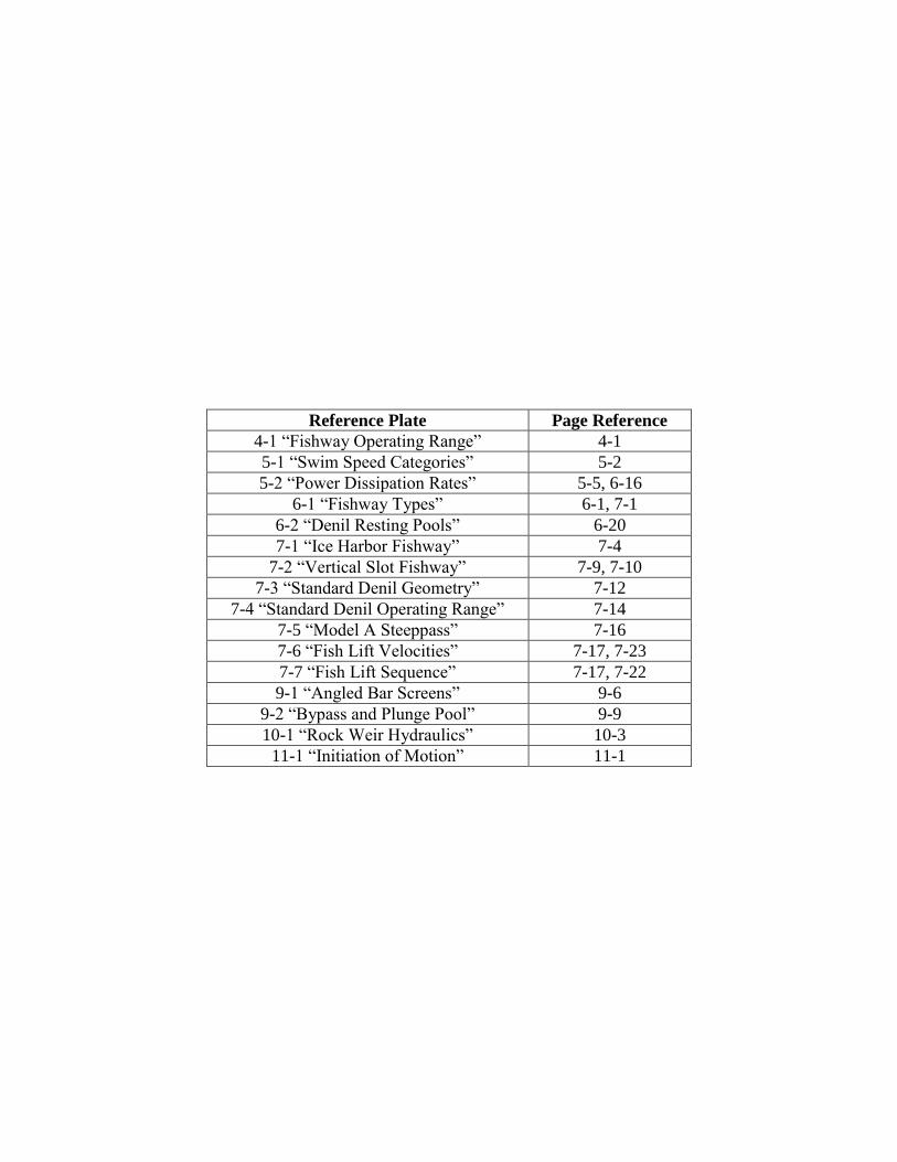
Reference Plate Page Reference
4-1 “Fishway Operating Range” 4-1
5-1 “Swim Speed Categories” 5-2
5-2 “Power Dissipation Rates” 5-5, 6-16
6-1 “Fishway Types” 6-1, 7-1
6-2 “Denil Resting Pools” 6-20
7-1 “Ice Harbor Fishway” 7-4
7-2 “Vertical Slot Fishway” 7-9, 7-10
7-3 “Standard Denil Geometry” 7-12
7-4 “Standard Denil Operating Range” 7-14
7-5 “Model A Steeppass” 7-16
7-6 “Fish Lift Velocities” 7-17, 7-23
7-7 “Fish Lift Sequence” 7-17, 7-22
9-1 “Angled Bar Screens” 9-6
9-2 “Bypass and Plunge Pool” 9-9
10-1 “Rock Weir Hydraulics” 10-3
11-1 “Initiation of Motion” 11-1

FLOW
FLOW
FLOW
J F M A M J J A S O N D WATER SURFACE ELEVATION5% 95%~30%
MAX
MIN
AT FLOWS LESS THAN STATIONCAPACITY, TURBINE DISCHARGE
DOMINATES RIVER DOWNSTREAM
NOMI
NAL F
ISH
PASS
AGE
SEAS
ONDAM
SPILLS,BYPASS FLOW
STATION CAPACITY
PASSAGE OCCURS UNDERADVERSE LEVELS OF
COMPETING FLOWS ANDFALSE ATTRACTION
PASSAGE OCCURS UNDERLOW TO MODERATECOMPETING FLOWS
HIGH DESIGN FLOW
LOW DESIGN FLOW
FISH
WAY
OPE
RATI
NG R
ANGE
1
LINEAR PRORATION OF DRAINAGE AREA WEIBULL EXCEEDANCE PROBABILITY HEAD-DISCHARGE RELATIONSHIP FISH PASSAGE OPERATING RANGE
Daily average river flows at ungagedproject sites can be linearly proratedfrom hydrologically similar gaged sites.
where:
Fish passage design flows, andassociated exceedance probabilities,are developed using daily average riverflows recorded during the fish passageseason over a sufficiently long periodof record (i.e., 10 to 30 years). High(5%) and low (95%) design flows can becompared to station capacity (~30%).
The spillway rating curve can berelated to fish passage design flows(and station capacity). For simple,uncontrolled spill, the weir equationrelates water surface elevation (orhead above crest) to discharge.
The operating range describes theriver flows and associated watersurface elevations under which thefish passage facility is safe, timely,and effective. Additionally, itillustrates when the fishway dischargecompetes with false attraction createdby the power station and spillway. Tomitigate adverse effects of competingflows, the Service recommends totalfishway discharge:
Qu is the ungaged flow (cfs)Qg is the gaged flow (cfs)Au is the site drainage (mi2)Ag is the gage drainage (mi2)
Note: the linear relationship is validonly when the drainage area of theungaged project site is of comparablesize to the drainage of the gage site.
where: P is the probability of rank mm is the rank of the flow eventn is the number of flow events
where: Qs is the total spillway flow (cfs)L is the length of spillway crest (ft)C is the weir coefficient ( - )H is the head above crest (ft)
Note: head is offset from the watersurface elevation by the crest elevation where: QT is the total fishway flow (cfs)
QP is the station capacity (cfs)
ABOVE OPERATING RANGE
BELOW OPERATING RANGE
3 5%
FISHWAY OPERATING RANGEUSFWS Northeast Region (R5), FACFish Passage Engineering, B. Towler, K. MulliganIssued 1/6/2017; replaces “Fishway Operating Range” 11/12/2015 REFERENCE PLATE 4-1
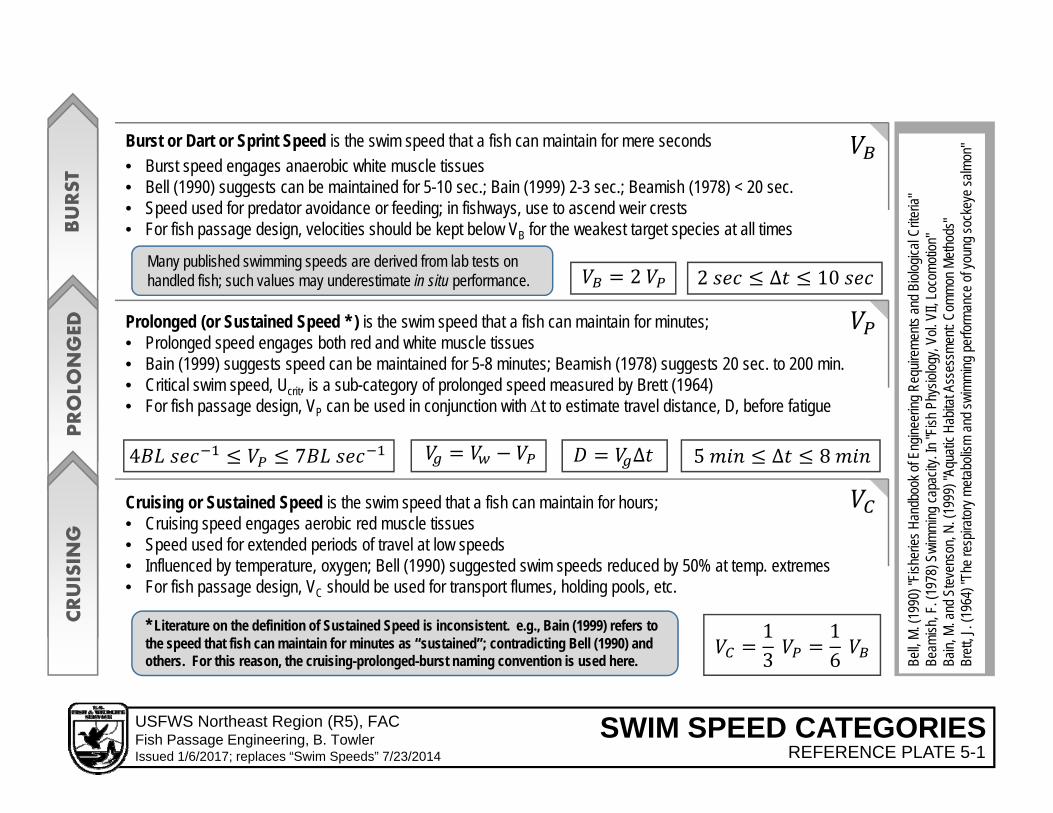
CRUISIN
GPROLO
NGED
BURST
Burst or Dart or Sprint Speed is the swim speed that a fish can maintain for mere seconds
Prolonged (or Sustained Speed * ) is the swim speed that a fish can maintain for minutes; • Prolonged speed engages both red and white muscle tissues• Bain (1999) suggests speed can be maintained for 5-8 minutes; Beamish (1978) suggests 20 sec. to 200 min.• Critical swim speed, Ucrit, is a sub-category of prolonged speed measured by Brett (1964)• For fish passage design, VP can be used in conjunction with t to estimate travel distance, D, before fatigue
Cruising or Sustained Speed is the swim speed that a fish can maintain for hours; • Cruising speed engages aerobic red muscle tissues• Speed used for extended periods of travel at low speeds• Influenced by temperature, oxygen; Bell (1990) suggested swim speeds reduced by 50% at temp. extremes• For fish passage design, VC should be used for transport flumes, holding pools, etc.
• Burst speed engages anaerobic white muscle tissues• Bell (1990) suggests can be maintained for 5-10 sec.; Bain (1999) 2-3 sec.; Beamish (1978) < 20 sec.• Speed used for predator avoidance or feeding; in fishways, use to ascend weir crests• For fish passage design, velocities should be kept below VB for the weakest target species at all times
2
4 7 ∆ 5 ∆ 8
2 ∆ 10
13
16
* Literature on the definition of Sustained Speed is inconsistent. e.g., Bain (1999) refers to the speed that fish can maintain for minutes as “sustained”; contradicting Bell (1990) and others. For this reason, the cruising-prolonged-burst naming convention is used here.
Many published swimming speeds are derived from lab tests on handled fish; such values may underestimate in situ performance.
Bell,
M. (1
990)
"Fish
eries
Han
dboo
k of E
ngine
ering
Req
uirem
ents
and B
iolog
ical C
riteria
"Be
amish
, F. (
1978
) Swi
mming
capa
city.
In "F
ish P
hysio
logy,
Vol. V
II, Lo
como
tion"
Bain,
M. a
nd S
teven
son,
N. (1
999)
"Aqu
atic H
abita
t Ass
essm
ent: C
ommo
n Meth
ods"
Br
ett, J
. (19
64) "
The r
espir
atory
metab
olism
and
swim
ming
per
forma
nce o
f you
ng so
ckey
e salm
on"
SWIM SPEED CATEGORIESUSFWS Northeast Region (R5), FACFish Passage Engineering, B. TowlerIssued 1/6/2017; replaces “Swim Speeds” 7/23/2014 REFERENCE PLATE 5-1
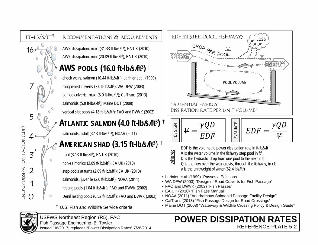
AWS POOLS (16.0 ft-lb/s/ft3) †
7
5
4
3
2
1
0
16
FT-LB/S/FT3
ENER
GY
DIS
SIPA
TIO
N F
ACT
OR
(ED
F)
“POTENTIAL ENERGYDISSIPATION RATE PER UNIT VOLUME”
EDF IN STEP-POOL FISHWAYS LOSS
POOL VOLUME
DESI
GN
EVAL
UATE
whe
re: EDF is the volumetric power dissipation rate in ft-lb/s/ft3
V is the water volume in the fishway step pool in ft3D is the hydraulic drop from one pool to the next in ftQ is the flow over the weir crests, through the fishway, in cfsγ is the unit weight of water (62.4 lbs/ft3)
ATLANTIC SALMON (4.0 ft-lb/s/ft3) †
AMERICAN SHAD (3.15 ft-lb/s/ft3) †
salmonids (5.0 ft-lb/s/ft3); Maine DOT (2008)
resting pools (1.04 ft-lb/s/ft3); FAO and DWVK (2002)
step-pools at turns (2.09 ft-lb/s/ft3); EA UK (2010)
non-salmonids (2.09 ft-lb/s/ft3); EA UK (2010)
trout (3.13 ft-lb/s/ft3); EA UK (2010)
salmonids, juvenile (2.0 ft-lb/s/ft3); NOAA (2011)
vertical slot pools (4.18 ft-lb/s/ft3); FAO and DWVK (2002)
Denil resting pools (0.52 ft-lb/s/ft3); FAO and DWVK (2002)
check weirs, salmon (10.44 ft-lb/s/ft3); Larinier et al. (1999)
baffled culverts, max. (5.0 ft-lb/s/ft3); CalTrans (2013)
salmonids, adult (3.13 ft-lb/s/ft3); NOAA (2011)
roughened culverts (7.0 ft-lb/s/ft3); WA DFW (2003)
AWS dissipation, min. (20.89 ft-lb/s/ft3); EA UK (2010)
AWS dissipation, max. (31.33 ft-lb/s/ft3); EA UK (2010)
RECOMMENDATIONS & REQUIREMENTS
• Larinier et al. (1999) “Passes a Poissons”• WA DFW (2003) “Design of Road Culverts for Fish Passage”• FAO and DWVK (2002) “Fish Passes”• EA UK (2010) “Fish Pass Manual”• NOAA (2011) “Anadromous Salmonid Passage Facility Design”• CalTrans (2013) “Fish Passage Design for Road Crossings”• Maine DOT (2008) “Waterway & Wildlife Crossing Policy & Design Guide”† U.S. Fish and Wildlife Service criteria
POWER DISSIPATION RATESUSFWS Northeast Region (R5), FACFish Passage Engineering, B. TowlerIssued 1/6/2017; replaces “Power Dissipation Rates” 7/26/2014 REFERENCE PLATE 5-2

VOLITIONAL
NON-VOLITIONALUPSTREAM DOWNSTREAM
CHUTES POOL-TYPE TRAP
POOL &WEIR
SERPENTINEICEHARBOR
LIFT LOCK
DENILSTEEPPASS
GUIDANCE
TECHNICAL NATURE-LIKE
BYPASS RAMPS
VERTICALSLOT
TRUCKPHYSICAL/EXCLUSION
BEHAVIORAL
TURBINES
STEP-POOL ROUGHENEDCHANNEL
BYPASS
TRAP
PARTIALRAMPS
MECHANICAL
POOL &CHUTE
TRANSPORT
TRUCKPLUNGE POOL
TAILWATER RIVERFOREBAYIMPOUNDMENTRIVER FISHWAY
NO
N-
VO
LITI
ON
AL
VO
LITI
ON
ALZone of Passage refers to the contiguous area of sufficient lateral, longitudinal, and vertical extent in which
adequate hydraulic and environmental conditions are maintained to provide a route of passage through a stream reach influenced by a dam (or stream barrier).
†
†
* The U.S. Fish and Wildlife Service does not generally accept turbine entrainment/passage as the primary downstream migration route.
*
3 ELE
MEN
TSOF
ATTR
ACTI
ON
LOCA
TION
–VEL
OCIT
Y -FL
OW
=ATTRACTIONFLOW
FISHWAYDISCHARGE + AWS
HYBRID
FISHWAY TYPESUSFWS Northeast Region (R5), FACFish Passage Engineering, B. TowlerIssued 1/6/2017; replaces “Fishway Types” 7/30/2014 REFERENCE PLATE 6-1

2 sin 42 2 sin 4
2 sin 4sin 4 2 sin 4
21 1
2cos4 tan4 1
FLOW
S0
H
LP
W
c
b
Width 1:8 slope 1:10 slope
3 (ft) hv 0.592 (ft) 0.5805 (ft)
K1 9.728355 7.697128
K2 1.802865 1.773244
4 (ft) hv 0.7894 (ft) 0.774 (ft)
K1 9.166344 7.160788
K2 1.779516 1.765067
Generalized Power Dissipation in Denil Resting Pools
Pool Sizing for Standard Denil Fishways
Denil Fishway Resting Pool Geometry
Denil Baffle
Effective Pool Volume
hv is the vertical (installed) height of the notch in the Denil baffle
Energy Dissipation Factor is the volumetric power dissipation in foot-pounds per second per cubic feet“Derivation and Application of the Energy Dissipation Factor in the Design of Fishways”B. Towler, K. Mulligan and A. Haro. Ecological Engineering 83 (2015) 208‐217
DENIL RESTING POOLSUSFWS Northeast Region (R5), FACFish Passage Engineering, B. TowlerIssued 1/6/2017; replaces “Denil Resting Pools” 10/27/2015 REFERENCE PLATE 6-2

Bw
W
L
BB
P
2’
tw
S0
A0
ICE HARBOR STANDARD DIMENSIONSW 10’ 11’ 12’ 13’ 14’ 16’ 18’ 20’ 25’
BW 3’ – 1” 3’ – 5” 3’ – 9” 4’ – 1” 4’ – 4” 5’ – 0” 5’ – 8” 6’ – 3” 7’ – 10”
BB 3’ – 10” 4’ – 2” 4’ – 6” 4’ – 10” 5’ – 4” 6’ – 0” 6’ – 8” 7’ – 6” 9’ – 4”
1’ – 10" 2’ – 0” 2’ – 3” 2’ – 5” 2’ – 7” 3’ – 0” 3’ – 0” 3’ – 0” 3’ – 0”
AO 12” x 12” 13” x 13” 14” x 14” 15” x 15” 16” x 16” 18” x 18” 18” x 18” 18” x 18” 18” x 18”
ICE HARBOR DESIGN RATIOS .
† U.S. Fish and Wildlife Service criteria
2
2 2
QW is the discharge over each weir crest in cfs
QO is the discharge though each orifice in cfs
Q is the total discharge through the fishway in cfs
23 2 0.86
†0.68
110
9
HW is the head on the weir crest in feet
HO is the head on the orifice in feet
†
ICE HARBOR FISHWAYUSFWS Northeast Region (R5), FACFish Passage Engineering, B. TowlerIssued 1/6/2017; replaces “Ice Harbor Fishway” 7/24/2014 REFERENCE PLATE 7-1

10 b
8 b
4.8
b2
um : max velocity (m/s)h: drop per pool (m)
Q: discharge through ladder (m3/s)y0 : depth in pool (m)
31
1.6 b
0.17 b
0.49 b
2 b
0.49 b
45o
Rajaratnam et al. (1986) Hydraulics of Vertical Slot Fishways, J. Hydr Engrg. 112(10)
*
*
b: slot width (m)S0: slope (m/m)
3.771.11DE
SIGN
1
witho
ut ba
ffle
plate
in slo
t
3.753.52DE
SIGN
2
with
6 inc
hba
ffle pl
ate
VERTICAL SLOT FISHWAYUSFWS Northeast Region (R5), FACFish Passage Engineering, B. TowlerIssued 1/6/2017; replaces “Vertical Slot Fishway” 10/27/2015 REFERENCE PLATE 7-2
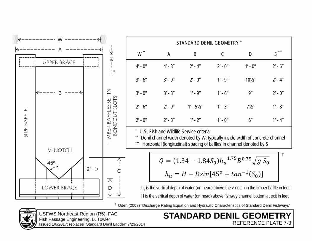
V-NOTCH
UPPER BRACE
B
A
D
C
LOWER BRACE
SID
E BA
FFLE
1”
2”
STANDARD DENIL GEOMETRY *
W ** A B C D S ***
4’ - 0” 4’ - 3” 2’ - 4” 2’ - 0” 1’ - 0” 2’ - 6”
3’ - 6” 3’ - 9” 2’ - 0” 1’ - 9” 10½” 2’ - 4”
3’ - 0” 3’ - 3” 1’ - 9” 1’ - 6” 9” 2’ - 0”
2’ - 6” 2’ - 9” 1’ - 5½” 1’ - 3” 7½” 1’ - 8”
2’ - 0” 2’ - 3” 1’ - 2” 1’ - 0” 6” 1’ - 4”
* U.S. Fish and Wildlife Service criteria** Denil channel width denoted by W; typically inside width of concrete channel *** Horizontal (longitudinal) spacing of baffles in channel denoted by S
W
45o 1.34 1.84 . .
† Odeh (2003) “Discharge Rating Equation and Hydraulic Characteristics of Standard Denil Fishways”
45
†
H is the vertical depth of water (or head) above fishway channel bottom at exit in feet
TIM
BER
BAFF
LES
SET
IN
BON
DO
UT
SLO
TS
hu is the vertical depth of water (or head) above the v-notch in the timber baffle in feet
STANDARD DENIL GEOMETRYUSFWS Northeast Region (R5), FACFish Passage Engineering, B. TowlerIssued 1/6/2017; replaces “Standard Denil Ladder” 7/23/2014 REFERENCE PLATE 7-3

STANDARD DENIL OPERATING RANGEUSFWS Northeast Region (R5), FACFish Passage Engineering, B. TowlerIssued 2/28/2017 REFERENCE PLATE 7-4
SPECIES OPERATINGRANGE
BAFFLE LENGTH (ft)5 6 7 8
River Herring(nominal 4” body depth)
High (ft) 3.25 4.25 4.75* 4.75*Low (ft) 1.75 1.75 1.75 1.75 (ft) 1.5 2.5 3 3
American Shad(nominal 6” body depth)
High (ft) 3.25 4.25 5 5.75Low (ft) 2.25 2.25 2.25 2.25
(ft) 1 2 2.75 3.5
Atlantic Salmon(nominal 8” body depth)
High (ft) 3.25 4.25 5 5.75Low (ft) 2.5 2.5 2.5 2.5 (ft) 0.75 1.75 2.5 3.25
High
Low
base
v-notch
2 body depths
BOTTOM OF EXIT CHANNEL
OPERATING RANGE
DATUM
OPERATING RANGES FOR 3 FT. AND 4 FT. DENIL FISHWAYS AT 1:8 OR 1:10 SLOPES
NOTES:The uppermost Denil baffle is installed at the break inslope between the exit channel and the sloped channel.Low and high operating levels are measured from thebottom of the exit channel.High operating level is set 6 inches below the top of thebaffle to avoid impact with the cross support.Ideally, the low and high operating levels correlate toheadpond elevations at the low design flow and highdesign flow, respectively.
* OPERATING LEVEL IS BASED ON A MAXIMUM
VELOCITY CRITERION FOR RIVER HERRING (4 FT/S)
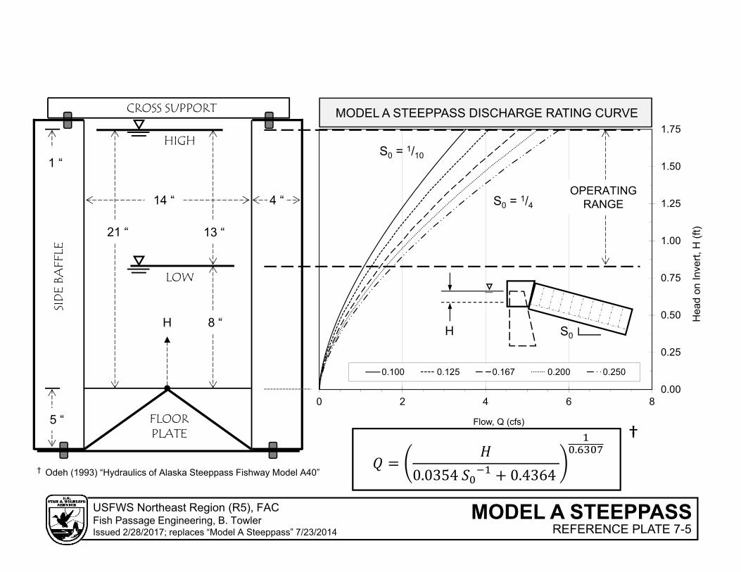
0.00
0.25
0.50
0.75
1.00
1.25
1.50
1.75
0 2 4 6 8
Hea
d on
Inve
rt, H
(ft)
Flow, Q (cfs)
0.100 0.125 0.167 0.200 0.250
CROSS SUPPORT
SID
E BA
FFLE
FLOORPLATE
8 “
OPERATINGRANGE
21 “ 13 “
S0 = 1/10
MODEL A STEEPPASS DISCHARGE RATING CURVE
0.0354 0.4364
.
HS0
† Odeh (1993) “Hydraulics of Alaska Steeppass Fishway Model A40”
†5 “
1 “
14 “ 4 “ S0 = 1/4
H
HIGH
LOW
MODEL A STEEPPASSUSFWS Northeast Region (R5), FACFish Passage Engineering, B. TowlerIssued 2/28/2017; replaces “Model A Steeppass” 7/23/2014 REFERENCE PLATE 7-5

VELOCITIES IN CRUISING SPEED RANGE TO ALLOW FISH TO HOLD WITHOUT FATIGUE
VELOCITIES IN PROLOGNED RANGE AS DIFFUSERS CONTRIBUTE TO FLOW
BURST TO PASS ENTRANCE
HOPPER& PIT
HOLDING POOL &MECHANICAL CROWDER
FLOORDIFFUSER
WALLDIFFUSER
ENTRANCECHANNEL
ENTRANCE& GATE
AUXILIARY WATER SYSTEM (AWS)
1 ‐1
.5 FT/S
1 ‐1
.5 FT/S
1 ‐3
FT/S
0.5 FT/S 0.5 FT/S
1.5 ‐4
FT/S
4‐6
FT/S
LIFT TOWER
BIOL
OGIC
AL LI
FT C
APAC
ITY
lift velocities, U.S. Fish and Wildlife Service criteria
crowding limit is valid for lift cycle times of 15 m or less†
AEB
H
REAR DIFFUSER
G
F
A. Attraction jet is created by acceleration due to entrance (lift) gate operations; jet typically results in 0.5 – 2 foot hydraulic drop into TW.
B. Flood walls and other lift components should be design to protect against a 50-year flood event.
C. Flow in the entrance channel, downstream of the diffusers, should be streamlined and free of eddies and aeration.
D. Diffuser velocities are maximum point velocities; upwelling and aeration from the AWS should be minimal.
E. Depth in lower flume should be greater than 4 ft. at all times.F. Flow above hopper and in holding pool should be free of aeration.G. As much AWS flow as possible should be discharge behind the hopper.H. AWS dissipators should be design to remove excess energy from flow.
D
C
601 1
nH is the lift biological capacity in fish per hourV is the volume of the component in ft3r is the cycle time in lifts per minutewf is the nominal weight of the target species in lbsCn is the non-target species allowancevc is the crowding limit: hopper = 0.10 ft3/lb
holding pool = 0.25 ft3/lb
†
FISH LIFT VELOCITIESUSFWS Northeast Region (R5), FACFish Passage Engineering, B. TowlerIssued 2/28/2017; replaces “Fish Lift” 7/27/2014 REFERENCE PLATE 7-6
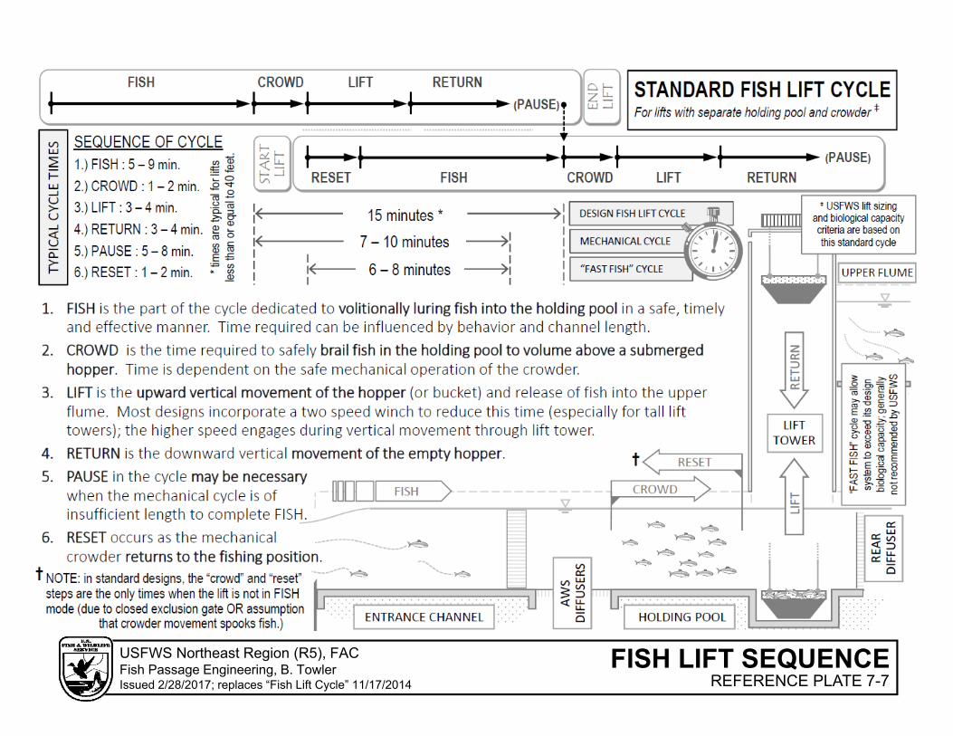
FISH LIFT SEQUENCEUSFWS Northeast Region (R5), FACFish Passage Engineering, B. TowlerIssued 2/28/2017; replaces “Fish Lift Cycle” 11/17/2014 REFERENCE PLATE 7-7
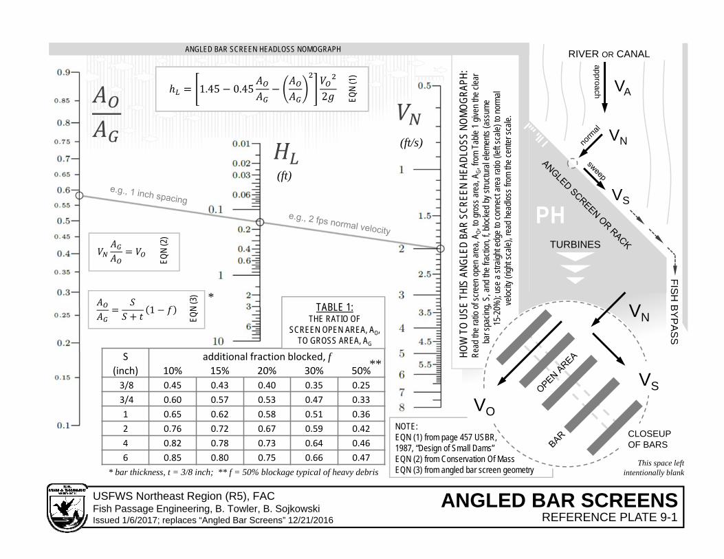
S additional fraction blocked, f(inch) 10% 15% 20% 30% 50%3/8 0.45 0.43 0.40 0.35 0.253/4 0.60 0.57 0.53 0.47 0.331 0.65 0.62 0.58 0.51 0.362 0.76 0.72 0.67 0.59 0.424 0.82 0.78 0.73 0.64 0.466 0.85 0.80 0.75 0.66 0.47
TURBINES
FISH
BY
PA
SS
VA
VS
RIVER OR CANAL
VNapproach
* bar thickness, t = 3/8 inch; ** f = 50% blockage typical of heavy debris
VN
VO
VS
CLOSEUPOF BARS
TABLE 1: THE RATIO OF
SCREEN OPEN AREA, AO, TO GROSS AREA, AG
1.45 0.45 2 EQN
(1)
1
EQN
(3)
EQN
(2)
NOTE: EQN (1) from page 457 USBR, 1987, “Design of Small Dams”EQN (2) from Conservation Of MassEQN (3) from angled bar screen geometry
PH
HOW
TO
USE
THIS
ANG
LED
BAR
SCRE
EN H
EADL
OSS
NOMO
GRAP
H:
Read
the r
atio o
f scre
en o
pen a
rea,
A O, to
gros
s are
a, A G
, from
Tab
le 1 g
iven t
he cl
ear
bar s
pacin
g, S,
and t
he fr
actio
n, f, b
locke
d by
stru
ctura
l elem
ents
(ass
ume
15-2
0%);
use a
stra
ight e
dge t
o con
nect
area
ratio
(left s
cale)
to no
rmal
veloc
ity (r
ight s
cale)
, rea
d hea
dloss
from
the ce
nter s
cale.
ANGLED BAR SCREEN HEADLOSS NOMOGRAPH
This space leftintentionally blank
(ft)
(ft/s)
*
**
ANGLED BAR SCREENSUSFWS Northeast Region (R5), FACFish Passage Engineering, B. Towler, B. SojkowskiIssued 1/6/2017; replaces “Angled Bar Screens” 12/21/2016 REFERENCE PLATE 9-1
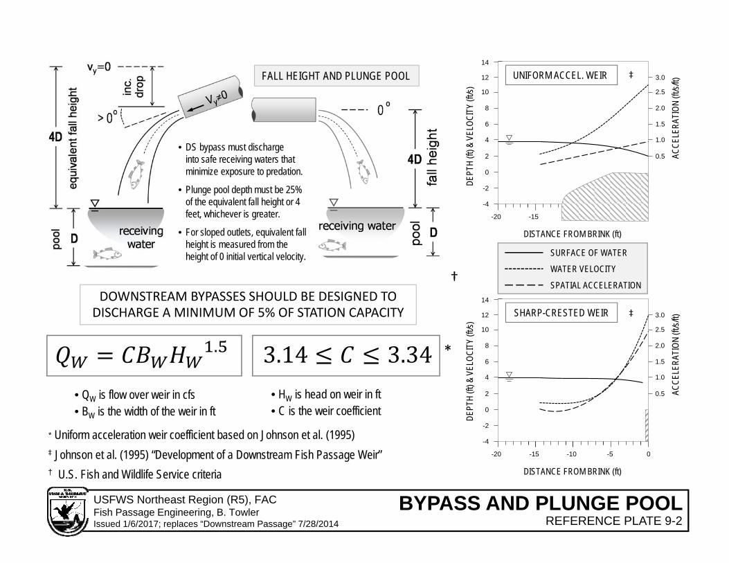
-4
-2
0
2
4
6
8
10
12
14
0.5
1.0
1.5
2.0
2.5
3.0
-20 -15 -10 -5 0
DISTANCE FROM BRINK (ft)
SHARP-CRESTED WEIR
DEPT
H (ft
) & V
ELOC
ITY
(ft/s)
ACCE
LERA
TION
(ft/s
/ft)
-4
-2
0
2
4
6
8
10
12
-20 -15
14
0.5
1.0
1.5
2.0
2.5
3.0
DISTANCE FROM BRINK (ft)
UNIFORM ACCEL. WEIR
DEPT
H (ft
) & V
ELOC
ITY
(ft/s)
ACCE
LERA
TION
(ft/s
/ft)
SURFACE OF WATER
WATER VELOCITY
SPATIAL ACCELERATION
FALL HEIGHT AND PLUNGE POOL
• DS bypass must dischargeinto safe receiving waters that minimize exposure to predation.
• Plunge pool depth must be 25% of the equivalent fall height or 4 feet, whichever is greater.
• For sloped outlets, equivalent fall height is measured from the height of 0 initial vertical velocity.
DOWNSTREAM BYPASSES SHOULD BE DESIGNED TO DISCHARGE A MINIMUM OF 5% OF STATION CAPACITY
.
• QW is flow over weir in cfs• BW is the width of the weir in ft
• HW is head on weir in ft• C is the weir coefficient
† U.S. Fish and Wildlife Service criteria
*
†
* Uniform acceleration weir coefficient based on Johnson et al. (1995)‡ Johnson et al. (1995) “Development of a Downstream Fish Passage Weir”
‡
‡
BYPASS AND PLUNGE POOLUSFWS Northeast Region (R5), FACFish Passage Engineering, B. TowlerIssued 1/6/2017; replaces “Downstream Passage” 7/28/2014 REFERENCE PLATE 9-2
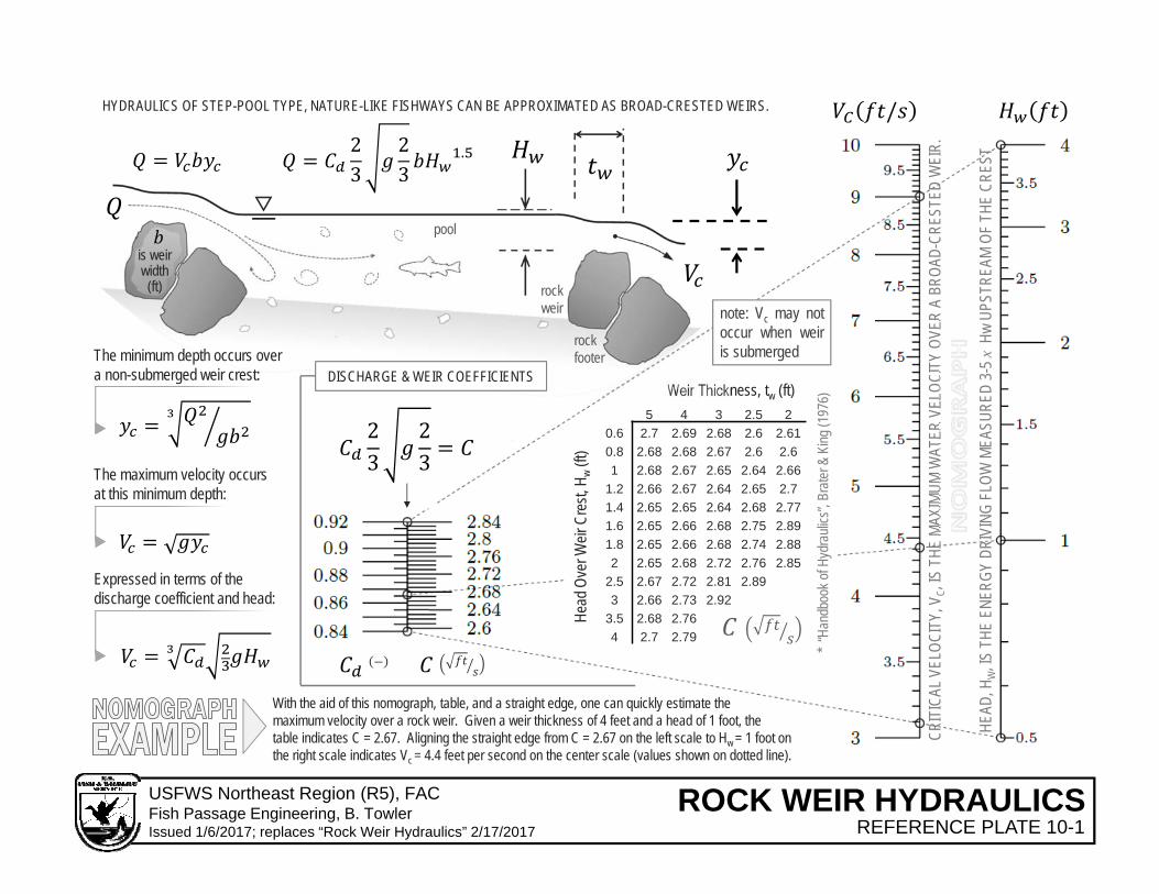
5 4 3 2.5 20.6 2.7 2.69 2.68 2.6 2.610.8 2.68 2.68 2.67 2.6 2.61 2.68 2.67 2.65 2.64 2.66
1.2 2.66 2.67 2.64 2.65 2.71.4 2.65 2.65 2.64 2.68 2.771.6 2.65 2.66 2.68 2.75 2.891.8 2.65 2.66 2.68 2.74 2.882 2.65 2.68 2.72 2.76 2.85
2.5 2.67 2.72 2.81 2.893 2.66 2.73 2.92
3.5 2.68 2.764 2.7 2.79
Head
Ove
r Weir
Cre
st, H
w(ft
)
Weir Thickness, tw (ft)
23
23
23
23
.
/
CRIT
ICAL
VEL
OCIT
Y, V
C, IS
THE
MAX
IMUM
WAT
ER V
ELOC
ITY
OVER
A B
ROAD
-CRE
STED
WEI
R.
HEAD
, HW
, IS T
HE E
NERG
Y DR
IVIN
G FL
OW M
EASU
RED
3-5 x
HwUP
STRE
AM O
F TH
E CR
EST
rockweir
pool
HYDRAULICS OF STEP-POOL TYPE, NATURE-LIKE FISHWAYS CAN BE APPROXIMATED AS BROAD-CRESTED WEIRS.
With the aid of this nomograph, table, and a straight edge, one can quickly estimate the maximum velocity over a rock weir. Given a weir thickness of 4 feet and a head of 1 foot, the table indicates C = 2.67. Aligning the straight edge from C = 2.67 on the left scale to Hw = 1 foot on the right scale indicates Vc = 4.4 feet per second on the center scale (values shown on dotted line).
The minimum depth occurs over a non-submerged weir crest:
The maximum velocity occurs at this minimum depth:
Expressed in terms of the discharge coefficient and head:
* “H
andb
ook o
f Hyd
rauli
cs”,
Brate
r& K
ing (1
976)
note: Vc may notoccur when weiris submerged
DISCHARGE & WEIR COEFFICIENTS
rockfooter
is weir width (ft)
ROCK WEIR HYDRAULICSUSFWS Northeast Region (R5), FACFish Passage Engineering, B. TowlerIssued 1/6/2017; replaces “Rock Weir Hydraulics” 2/17/2017 REFERENCE PLATE 10-1

∗ 0.0577
≅1.65
0.000.010.020.030.040.050.060.070.080.090.10
1.E+0 1.E+1 1.E+2 1.E+3 1.E+4 1.E+5 1.E+6
∗
Dimen
sionless S
hear Stress
Particle Reynolds Number
SIL
T
SAND GRAVEL BOUL
DERno motion
increasing likelihoodof particle suspension
1 ≅ 1.65
1.13 ∙ 10
forsilica
ft2/s
Shields (1936) “Appl. of Similarity Princ. & Turb. Res. to Bed Load Movement”
CLAY
SILT
SAND
GRAVEL
BOULDER
0.000154 in0.00391 mm
0.00246 in0.0625 mm
0.787 in2.0 mm
10.0 in256 mm
The Shields Diagram is a graphical representation of the ShieldsCriterion, a critical shear stress parameter used to calculate theinitiation of motion of sediment in fluid flow (Shields, 1936).Initiation of motion can be predicted through the relationshipbetween the Shields Criterion, or Shields Number, and the particleReynolds Number. Brownlie (1981) and Parker et al. (2003)provided analytical forms of this shear stress-grain size relationshipthat can be expressed in terms of the hydraulic geometry of rivers.
(grain size)
UDDEN-WENTWORTHGRAIN SIZE SCALE
∗ ≃ 0.03
EXAMPLE: A small stream, with a mean bank-full depth of 4 feet, falls 2 vertical feet for every 1000 horizontal feet. Water temperature is 65 degrees F. Determine if a median grain size of 1 inch meets the Shields Criterion for threshold of motion.
1.57 ⋅ 10 ; motion!
∗1.65
32.174 ft/s2
Parker et al, (2003) “Effect of Floodwater Extr. on Mountain Stream Morphology”
waterat 65F
MODIFIED SHIELDS-PARKER FUNCTION∗ 1
2 0.22 . 0.06 ⋅ 10 . .
INITIATION OF MOTIONUSFWS Northeast Region (R5), FACFish Passage Engineering, B. TowlerIssued 1/6/2017 REFERENCE PLATE 11-1

Appendix B
Fishway Inspection Guidelines

FISHWAY INSPECTION GUIDELINES TR‐2013‐01 June 5, 2013
Brett Towler 1, Curtis Orvis 1, Donald Dow 2, Alex Haro 3 1 U.S. Fish and Wildlife Service, Fisheries, Northeast Regional Office, Hadley, Massachusetts 2 NOAA National Marine Fisheries Service, Maine Field Station, Orono, Maine 3 U.S. Geological Survey, Conte Anadromous Fish Research Center, Turners Falls, Massachusetts
Fish Passage Technical Report Series, UMass Amherst
2
Authors: Brett Towler, Ph.D., P.E., P.H. Hydraulic Engineer Adjunct Assistant Professor Fish Passage Engineering Division Dept. of Civil and Environmental Engineering U.S. Fish and Wildlife Service University of Massachusetts Amherst 300 Westgate Center Drive 130 Natural Resources Road Hadley, MA 01035 Amherst, MA 01003 413‐253‐8727 [email protected] [email protected]
Curtis Orvis, P.E. Chief, Fish Passage Engineering Division U.S. Fish and Wildlife Service 300 Westgate Center Drive Hadley, MA 01035 413‐253‐ 8488 [email protected]
Donald A. Dow, III, P.E. Hydro/Fish Passage Engineer Integrated Statistics; contracted to: NOAA's National Marine Fisheries Service 17 Godfrey Drive Suite 1 Orono, ME 04473 207‐866‐8563 [email protected]
Alex Haro, Ph.D. Research Ecologist Adjunct Assistant Professor Conte Anadromous Fish Research Center Dept. of Environmental Conservation U. S. Geological Survey University of Massachusetts Amherst 1 Migratory Way 160 Holdsworth Way Turners Falls, MA 01376 Amherst, MA 01003 413‐863‐3806 [email protected]
Suggested citation: University of Massachusetts Amherst, Fish Passage Technical Report, TR‐2013‐1
(June 2013), UMass Amherst Libraries, University of Massachusetts.
Available at: http://scholarworks.umass.edu/fishpassage/

3
1.0 General This technical report provides guidance for engineers, biologists, operators, regulators and dam owners
involved in the inspection of fishways at dams. Volitional fish ladders, fish lifts, and other fish passage
and protection facilities are devices of varying complexity frequently integrated into sophisticated
reservoir management and hydropower installations. As with any device, maintenance of fish passage
facilities is necessary to ensure their proper operation. Improper operation of fishways may limit or
eliminate entire year classes of diadromous fish. Routine fishway inspections are a critical component of
an overall fish passage operation and maintenance plan.
2.0 Definition of a Fishway
Fishway (or fish pass) is a generic term for those structures and measures which provide for safe, timely,
and effective upstream and downstream fish passage. Fishways include physical structures, facilities, or
devices necessary to maintain all life stages of fish, and operations and measures related to such
structures, facilities, or devices which are necessary to ensure their effectiveness. Examples include, but
are not limited to, volitional fish ladders, fish lifts, bypasses, guidance devices, and operational
shutdowns.
3.0 Types of Fishways
Fish passes can be broadly categorized as either technical fishways or nature‐like fishways. Nature‐like
fishways include bypass channels, rock ramps and other passage structures that approximate (either
functionally or aesthetically) natural river reaches. Technical fishways employ engineering designs that
are typically concrete, aluminum, polymer, and wood, with standardized dimensions, using common
engineering construction techniques. The physical and hydraulic structure of nature‐like fishways is
markedly different from technical fishways, and the inspection of nature‐like fishways is beyond the
scope of this report. Technical fishways (hereafter, simply fishways) can be further categorized as
upstream or downstream passes. Figure 1 shows these categories and common types of fishways.
Baffled‐Chute Fishways: Baffled chutes are a subset of upstream volitional ladders designed to reduce
velocities in a sloping channel to levels against which fish can easily ascend. Baffled chutes common to
the Eastern United States include:
Steeppass Model A 21‐inch wide, 27‐inch tall, baffled aluminum channel
Steeppass Model A40 40‐inch tall, deepened version of the Model A steeppass
Standard Denil 2‐to‐4 foot‐wide (typically concrete) channel with wooden baffles
Pool‐Type Fishways: Pool‐type upstream fishways are designed to link headwater and tailwater through
a series of (typically concrete) pools through and over which water cascades slowly. Pool‐types include:
Pool‐and‐Weir pools often separated by rectangular weirs; may also include orifices
Ice Harbor variant of the pool‐and‐weir type; characterized by two weirs separated
by central C‐shaped vertical baffle

4
Half Ice Harbor modified Ice Harbor; characterized by one weir opposite an L‐shaped
vertical baffle
Vertical Slot flow through pools via deep, narrow, full‐depth slots rather than an
overflow weir
Serpentine similar to a vertical slot with a winding, tortuous horizontal flow path
Fish Lifts/Locks: Fish lifts or elevators are non‐volitional upstream fishways that attract fish into an
entrance channel and mechanically crowd them above a hopper before lifting them into an
impoundment (or alternatively, into an exit channel hydraulically linked to an impoundment). Fish lifts
differ from volitional ladders in that they usually possess numerous mechanical, hydraulic, and electrical
components. A fish lock is similar to a lift where the hopper and lift tower is replaced with a full‐height,
columnar structure (i.e., lock) that can be filled with water. Fish locks are rare on Atlantic coast and are
therefore not addressed directly in this document.
Figure 1. Common fishway types in the eastern U.S.
technical
fishways
nature‐like
fishways
stream
crossings
upstream downstream
non‐volitional volitional (ladders)
lift lock pool‐type hybrid
types
baffled‐chute
steeppass
Model A
steeppass
Model A40
Standard
Denil
Ice
Harbor
pool‐and‐weir serpentine vertical
slot
trap &
transport
operational and
non‐structural measures

5
Downstream Passage: Facilities designed to protect and pass out‐migrating fish are varied and diverse
ranging from simple overflow weirs to highly complex guidance screens with attraction water recycling
systems, bypasses, plunge pools, and fish sampling systems. Typically, these systems consist of four
primary components:
Physical/behavioral guidance screen or bar rack
Bypass opening (e.g., weir, chute, sluice, or orifice)
Conveyance structure (i.e., open channel or pressurized conduit)
Receiving pool
The bypass opening is intended to function as a safe outlet for fish migrating downstream past the dam.
Exclusion screens or behavioral guidance screens (or racks) are designed to create physical and/or
hydraulic cues that encourage fish to move towards and pass through the bypass opening. Receiving
waters or plunge pools are typically necessary to safely transition fish to waters below the dam.
Receiving waters generally refer to the existing tailrace or tailwater below the dam; plunge pools are
separately excavated pits, or built‐up basins, which provide adequate depth to prevent plunging fish
from impacting the channel bottom, concrete apron, or other submerged feature.
Eel Pass: Eel passes (or eelways) are upstream passage structures that provide a path over the dam for
catadromous elvers and juvenile eels. These structures typically consist of an attraction water delivery
system incorporated into ramp lined with various wetted media which eels use to propel themselves up
the ramp. They may provide a full volitional pathway for up‐migrating eels or terminate in a trap or lift.
The above list represents some of the more common fishways used to mitigate the impacts of stream
barriers on the east coast of the United States. However, the reader should be aware that there are
numerous other types, variations of these technologies, and auxiliary components not described herein.
4.0 An Approach to Fishway Inspection
The holistic definition of a fishway (as described in Section 2.0) should convey the importance of
assessing fishway conditions in a comprehensive manner that considers a) the path of fish past a barrier,
and b) the aggregate passage conditions and timing due to the interaction of numerous (non‐fishway)
structures and operations. Unfortunately, such myriad interactions cannot be enumerated or described
in a generalized way. Consider these examples:
the strength of the hydraulic cue created by a fishway entrance jet may be influenced by
tailwater elevation (which, in turn, may be affected by turbine discharge);
salmonids may ascend over weirs under plunging flow conditions, clupeids may not;
the efficacy of fishway attraction flow may be compromised by the sequence of turbine
operations resulting in delays in upstream migration;
sweeping velocities in front of a downstream bypass guidance screen may be influenced by
generation, trash loading, or spill; and

6
water surface elevations throughout a ladder may be influenced by flashboard failure at the
upstream spillway.
Therefore, the reader is strongly encouraged to keep the broadest definition of a fishway in mind when
performing inspections so as to avoid a myopic view of individual fishway components that may obscure
the integrated functionality critical to the proper operation of these facilities.
Certain anomalous conditions or occurrences are seen at more frequently fishways. Inspectors should
be keenly aware of, and document, these issues:
Damage to, or degradation of, structural components
Visual or auditory evidence of poorly functioning mechanical components
Leaf litter, large woody debris, or sediment in the fishway
Adverse water levels in and adjacent to the fishway
Eddies, jumps, aeration and other unusual hydraulic phenomena
Evidence of fish delay, entrainment, impingement, injury, or mortality
Original design deficiencies
5.0 Equipment
Inspectors should anticipate the equipment needed to properly perform the inspection. Furthermore,
ensuring the equipment is in proper working order is a prudent step in pre‐inspection planning. Battery
operated electronic equipment (e.g., total station, camera) should be charged. Digital instruments (e.g.,
acoustic Doppler velocity meter) may require calibration. In general, all equipment should be checked
prior to traveling to the site of the dam or barrier.
The following is a list of items which may prove useful during inspection:
Inspection checklist Suggested checklist attached to this document
Pencil and field book Checklist may be insufficient to document anomalous conditions
Voice recorder Digital recordings can augment notes
Digital camera Photographs and video of field conditions are essential to inspection
Staff gage Gage (e.g. survey rod) used to measure water surface elevations
Tape measure Allows measurement of relevant fishway geometry
Flashlight Covered channels and transitions may not be lit
Lumber crayon Inspector may wish to mark water levels during operational changes
Watertight boots Recommended for inspecting de‐watered fishways
Velocity meter Useful in assessing velocity barriers and impingement “hot spots”
Survey/hand level For precise measurement of HGL or elevation changes
Given the proximity to moving water, heavy equipment, and the steep terrain associated with dams,
fishways are potentially hazardous sites. Safety equipment is always recommended. Moreover,
fishways are often located at large hydroelectric facilities where rigorous safety programs have been
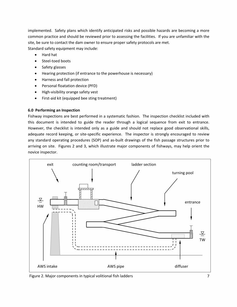
7
implemented. Safety plans which identify anticipated risks and possible hazards are becoming a more
common practice and should be reviewed prior to assessing the facilities. If you are unfamiliar with the
site, be sure to contact the dam owner to ensure proper safety protocols are met.
Standard safety equipment may include:
Hard hat
Steel‐toed boots
Safety glasses
Hearing protection (if entrance to the powerhouse is necessary)
Harness and fall protection
Personal floatation device (PFD)
High‐visibility orange safety vest
First‐aid kit (equipped bee sting treatment)
6.0 Performing an Inspection
Fishway inspections are best performed in a systematic fashion. The inspection checklist included with
this document is intended to guide the reader through a logical sequence from exit to entrance.
However, the checklist is intended only as a guide and should not replace good observational skills,
adequate record keeping, or site‐specific experience. The inspector is strongly encouraged to review
any standard operating procedures (SOP) and as‐built drawings of the fish passage structures prior to
arriving on site. Figures 2 and 3, which illustrate major components of fishways, may help orient the
novice inspector.
Figure 2. Major components in typical volitional fish ladders
ladder section
turning pool
entrance
diffuser
counting room/transport exit
AWS pipe
HW
TW
AWS intake

8
Information gathered on anomalous conditions (either on this checklist or in supplemental records)
should include these three important elements:
1. Location: Record the location where conditions are of interest. If the location is a standard
fishway component then identify it as such:
“fishway entrance gate”
“3rd turning pool upstream of the entrance”
“downstream bypass plunge pool”
If the location possesses no standard name, describe it in relation to a clearly identifiable, datum
or nearby feature:
“… 7 feet upstream of the antenna array bond‐out”
“… overflow pool at elevation 110.5 feet USGS”
“… on intake rack 30 feet out from right abutment”
2. Extent: Measure or estimate the dimension(s) of the problem or condition:
“2‐foot by 3‐foot section of the wedge‐wire screen”
“overtopping of 3‐feet of water”
“6 inches of sediment”
3. Detail: A brief description of the condition should be included:
“a swirling horizontal eddy forms in the turning pool during operation”
“an impassable hydraulic drop forms over the weir crest”
“fish trapped behind skimmer wall

9
7.0 Checklist
The FISHWAY INSPECTION CHECKLIST included in this technical report is formatted to guide the
inspector in a sequential manner moving down‐gradient from the fishway exit to the fishway entrance.
Numbered checklist items are written as questions requiring the user to verify the structural, hydraulic,
or operational functionality of fishway components. Comment space is provided at the end of each
major section. These major sections are:
Reason for Inspection: Fishways are often inspected during the peak of a migratory fish run to evaluate
the facility while operating at design capacity. However, they may be inspected at opening (i.e., start of
the season), shut‐down, or post‐flood to assess damage. Recording the reason for the inspection
provides important context for the subsequent notes.
Fishway Status: It is equally important to note whether or not the fishway is de‐watered and whether or
not it is operating at the time of the site visit. For pre‐ (or post‐) season inspections, the need to
examine specific components may dictate the status of the fishway. For instance, a watered, operating
fishway may allow for an assessment of the hydraulics, but will also obscure potential problems below
the waterline.
lift tower
hopper
entrance
diffuser
crowder holding pool
counting room/transport exit
AWS pipe
HW
TW
return pipe AWS intake
Figure 3. Major components in typical non‐volitional fish lifts

10
Hydrology & Ecology: Fishways vary according to site hydrology and the target species for which they
were designed. The inspector should note the target species and mark the approximate migration
periods on the upstream (U/S) and downstream (D/S) migration scales. Comments on fish health issues
(i.e. VHS, descaling, parasitism) and noting the presence of invasive species may prove useful to
resource agencies.
The river flow influences numerous operational aspects of fishway operation including the headpond
and tailwater elevation, adjustable gate settings, and entrance jet velocities. The USGS is the principal
agency tasked with maintaining stream gages in the U.S. If the dam owner/operator cannot provide the
current river flow, the USGS stream gage network should be used:
http://waterdata.usgs.gov/nwis
Additionally, the inspector may consider recording the water temperature at the fishway entrance
channel and in the headpond. The movement of many migratory species is linked to water
temperature. Surface water temperatures in the impoundment are typically higher than the river and
may be further influenced municipal treatment plants and industrial cooling water. A significant
difference in fishway temperature versus headpond temperature could indicate undue solar warming in
the AWS or fishway pools.
Hydropower Operations: It is well known that dams are barriers to the passage of riverine and migratory
aquatic species. Hydroelectric facilities present additional fishway operational challenges and represent
a significant hazard to down‐migrating fish. Inspectors should document powerhouse capacity, unit
type, methods of remote operation, and any operational links between the fishway and turbine
sequencing. For example, turbines adjacent to the fishway entrance may be prioritized to enhance
attraction flow. Similarly, Kaplan units (which may be less harmful to some species than comparable
Francis units) may be preferentially operated during the downstream migration period. Turbine
rotational speed often correlates to mortality, and could be documented if the information is available
on site. For estimates of approach velocity (in the forebay), inspectors may choose to estimate the
turbine intake dimensions. For inspections of dams without powerhouses, users may strike through this
section.
Upstream Fishway Exit: The exit typically refers to those components that connect the ladder or lift to
the headpond or river upstream of the barrier. It is important to note that the upstream fishway exit is
also the hydraulic intake to the fishway (and these seemingly contradictive definitions can cause
confusion). The inspector should look for conditions that may prevent or delay fish from quickly exiting
the fishway such as debris accumulation, partially opened gates, dark shadows, bright lights and noise‐
inducing structures. One should also document any evidence that fish are not quickly moving up into
the impoundment (and beyond the immediate hydraulic influence of adjacent flood gates, turbines, or
other water intakes). If possible, record the headpond water surface elevation.

11
Ladder: The chute, channel, or pools connecting the entrance to exit are commonly called the ladder.
Debris, sediment and failure of wooden water‐retaining structures (e.g., blocking boards, weir crests)
are the most common causes of operational failure in otherwise‐effective fishways. Though time‐
consuming, the entire ladder can be rigorously inspected for problems in a de‐watered state. In an
operating and watered state, blockages and board failures can be more quickly identified by the
anomalous water surface elevations and flow patterns these problems create. For inspections of lifts,
users may strike through this section.
Fishlift: The lift includes the lift tower, holding pool, hopper (i.e., bucket), crowder, brail, and any
associated electrical, hydraulic and mechanical components. It also includes any water conveyance
between the exit and the entrance (e.g., transfer from hopper to exit flume). Grating on the crowder
and exclusion gate behind the hopper are particularly susceptible to debris blockage. Debris can lead to
altered flow patterns and velocities, but sharp woody debris lodged in the grating may also injure fish. It
is recommended that the inspector observe a complete lift cycle while on site; if possible, the lift cycle
should be timed to ensure it is operating within design parameters. Unusual sounds, binding, and
vibration during operation are indicators of a problem. Where possible, the operators should
accompany the inspectors; operators can provide invaluable insight into the condition of the equipment.
For inspections of ladders, users may strike through this section.
Upstream Fishway Entrance: For both lifts and ladders, the entrance consists of a channel of varying
length leading fish into the ladder/lift from the tailwater below the dam. Larger hydropower facilities
may include collection galleries that consist of a flume with manifold gated entrances. Regulating the
attraction jet velocity is perhaps the most critical aspect influencing the effectiveness of the entrance.
In the presence of varying tailwater, velocities are controlled through installation of (overflow) weir
boards in a slot at the entrance. Alternatively, larger facilities may be equipped with an (overflow) lift
gate. Regardless, the gate or boards serve as submerged weirs that locally accelerate the flow to create
an attraction jet. The water surface elevations between the entrance channel and the tailwater
correlate to the strength of the attraction jet and should be diligently recorded by the inspector. If
possible, record the tailwater elevation.
Auxiliary Water System: The fishway must produce a sufficiently strong attraction jet at the entrance
often in the presence of other competing flows (e.g., spill, powerhouse discharge). Lifts generate no
flow by themselves, and ladders may not discharge enough flow to create an adequate attraction signal.
Auxiliary Water Systems (AWS) provide an additional source of water to augment the attraction flow.
AWS commonly consist of an intake at the headpond, anti‐vortex devices, a headgate, a conveyance
pipe, valves, a diffuser chamber, and diffuser outlets. Most of these components are underground or
underwater; however the inspector should examine the intake screen for blockages and, if possible,
verify the current AWS discharge (with the dam owner or operator).
Downstream Passage Facilities: Access to much of the downstream passage system (e.g., floating boom,
intake racks) may be problematic. At a minimum, fishway inspectors should examine the accessible

12
racks/screens, downstream bypass, bypass weir, any fish sampling systems, conveyance structures, and
plunge pool. For rack or screens that cannot be measured directly, inspectors may estimate depths and
widths (or inquire of the dam owner and/or operator). Unfavorable hydraulic conditions (e.g., lack of
guidance, excessive velocities, impinging jets), debris blockages, partially open gates which obstruct fish
movement, and incorrectly installed bypass weirs are among the more common deficiencies.
Counting & Trapping: A minority of fishways are equipped with counting rooms and trapping facilities.
While not integral to the passage of fish, these elements may support critical monitoring and research
programs. Where appropriate, trap gates and lift mechanisms should be operated and examined for
serviceability and fish safety. A courtesy engineering assessment of the counting room may be
welcomed by the operator and/or resource agency biologist.
Eel Pass: This section is intended to capture elements related to upstream eel passage. Downstream eel
passage (if it exists) can be addressed in the “Downstream Passage Facilities” section. Critical elements
of the eelway include ensuring the ramp is sufficiently wet and that the media is clean of debris. If the
ramp terminates in a trap, check to ensure the trap box receives adequate flow and that eels cannot
escape. If the trap box appears overcrowded, notify the project or agency biologist immediately.
Uncovered ramps may be susceptible to predation. Additionally, make observations on the attraction
water supply system (e.g., water source, approximate flow, flow conditions at the base of the ramp,
leakages)
Inspections are time‐consuming and demand one’s full attention. Advance preparation will enhance the
quality of the inspection. Therefore, it is recommended that the inspector fill out as much of the form
as possible prior to arriving on site. As discussed in Section 6.0, fishway SOPs and as‐built drawings are
valuable sources of information that should be reviewed in advance.
8.0 Disclaimer
These fishway inspection guidelines were developed by the authors with input from other subject‐
matter experts. They are intended for use by persons who have the appropriate degree of experience
and expertise. The recommendations contained in these guidelines are not universally applicable and
should not replace site‐specific recommendations, limitations, or protocols.
The authors have made considerable effort to ensure the information upon which these guidelines are
based is accurate. Users of these guidelines are strongly recommended to independently confirm the
information and recommendations contained within this document. The authors accept no
responsibility for any inaccuracies or information perceived as misleading. The findings and conclusions
in these guidelines are those of the authors and do not necessarily represent the views of the University
of Massachusetts Amherst, Integrated Statistics, the U.S. Fish and Wildlife Service, the National Oceanic
and Atmospheric Administration, or the United States Geological Survey.

13
9.0 Acknowledgements
Reviews, important information, and valuable insight were provided by Steve Gephard, Connecticut
DEEP Inland Fisheries Division; Gail Wipplehauser and Oliver Cox, Maine Department of Marine
Resources; Ed Meyer, National Oceanic and Atmospheric Administration; Steve Shepard, John Warner,
and Jesus Morales, U.S. Fish and Wildlife Service; and Ben Rizzo, U.S. Fish and Wildlife Service (retired).
The authors thank these individuals for their thoughtful contributions.

FISHWAY INSPECTION CHECKLIST
Dam/Project Name: __________________________________ Waterway: _________________________________
Owner (Organization): ________________________________ Date/Time: _________________________________
Inspector(s): ____________________________________________________________________________________
Owner’s Representative(s) On-site: __________________________________________________________________
Comments: _____________________________________________________________________________________
Reason for inspection: opening during season/run shutdown construction
other ______________________________________________________________
Fishway Status: de-watered/non-operational watered/operational
watered or underwater/non-operational damaged/operational
unknown damaged/non-operational
1. Target species for fishway: ________________________________________________________________
2. U/S migration period:
3. U/S fish passage design flow: HIGH (cfs)
LOW (cfs)
4. D/S migration period:
5. Drainage & current river flow (if known): (mi2) (cfs)
Comments on Hydrology & Ecology: _________________________________________________________
_______________________________________________________________________________________
6. Is the fishway and dam part of a hydroelectric project? YES NO
7. Is there a powerhouse at this location? YES NO
8. Powerhouse hydraulic capacity: (cfs)
9. Project generating capacity: (MW)
10. Number and type of hydroelectric turbines:
Francis: Kaplan: Bulb: Other:
11. Are units sequenced on/off to enhance fish passage? YES NO
If YES, describe operations: _________________________________________________________________
________________________________________________________________________________________
Comments on Hydropower Operations: _______________________________________________________
________________________________________________________________________________________
J F M A M J J A S O N D
J F M A M J J A S O N D
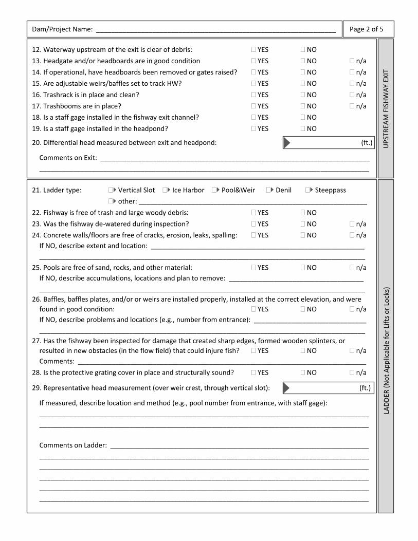
Dam/Project Name: ________________________________________________________________ Page 2 of 5
12. Waterway upstream of the exit is clear of debris: YES NO
13. Headgate and/or headboards are in good condition YES NO n/a
14. If operational, have headboards been removed or gates raised? YES NO n/a
15. Are adjustable weirs/baffles set to track HW? YES NO n/a
16. Trashrack is in place and clean? YES NO n/a
17. Trashbooms are in place? YES NO n/a
18. Is a staff gage installed in the fishway exit channel? YES NO
19. Is a staff gage installed in the headpond? YES NO
20. Differential head measured between exit and headpond: (ft.)
Comments on Exit: ________________________________________________________________________
________________________________________________________________________________________
21. Ladder type: Vertical Slot Ice Harbor Pool&Weir Denil Steeppass
other: _____________________________________________________________
22. Fishway is free of trash and large woody debris YES NO
23. Was the fishway de-watered during inspection? YES NO n/a
24. Concrete walls/floors are free of cracks, erosion, leaks, spalling: YES NO n/a
If NO, describe extent and location: _________________________________________________________
_______________________________________________________________________________________
25. Pools are free of sand, rocks, and other material: YES NO n/a
If NO, describe accumulations, locations and plan to remove: ____________________________________
_______________________________________________________________________________________
26. Baffles, baffles plates, and/or or weirs are installed properly, installed at the correct elevation, and were
found in good condition: YES NO n/a
If NO, describe problems and locations (e.g., number from entrance): ______________________________
_______________________________________________________________________________________
27. Has the fishway been inspected for damage that created sharp edges, formed wooden splinters, or
resulted in new obstacles (in the flow field) that could injure fish? YES NO n/a
Comments: _____________________________________________________________________________
28. Is the protective grating cover in place and structurally sound? YES NO n/a
29. Representative head measurement (over weir crest, through vertical slot): (ft.)
If measured, describe location and method (e.g., pool number from entrance, with staff gage):
________________________________________________________________________________________
________________________________________________________________________________________
Comments on Ladder: _____________________________________________________________________
________________________________________________________________________________________
________________________________________________________________________________________
________________________________________________________________________________________
________________________________________________________________________________________
________________________________________________________________________________________

Dam/Project Name: ________________________________________________________________ Page 3 of 5
30. Was the lift cycled (operated) during this inspection? YES NO
31. Holding pool is relatively free of debris: YES NO
32. Hopper raises smoothly without binding or vibrating: YES NO n/a
33. Mechanical crowder opens/closes/operates properly: YES NO n/a
34. Crowding proceeds in a manner consistent with design: YES NO
If NO, describe problems and locations: _______________________________________________________
________________________________________________________________________________________
35. Hopper properly aligns with chute during exit channel transfer: YES NO n/a
36. Is the exit channel (between lift and exit) free of debris? YES NO n/a
37. Other mechanical components appear in good working order: YES NO
If NO, describe problems and locations: _______________________________________________________
________________________________________________________________________________________
38. Lift appears free of sharp corners that could injure fish: YES NO
39. Lift cycles manually or automatically: Manual Automatically
40. Cycle time of lift (fishing to fishing): (min.)
41. Hopper volume (if known): (ft3)
Comments on Lift: ________________________________________________________________________
________________________________________________________________________________________
________________________________________________________________________________________
42. Is the approach to the entrance(s) free of debris and obstructions? YES NO
43. Are boards properly installed in the entrance? YES NO n/a
44. Are adjustable gates tracking TW? YES NO n/a
45. If operational, does the entrance jet appear appropriate? YES NO n/a
46. Is a staff gage installed in the fishway entrance channel? YES NO
47. Is a staff gage installed in the tailwater area? YES NO
48. Differential head measured between entrance and tailwater: (ft.)
Comments on Entrance: ___________________________________________________________________
________________________________________________________________________________________
________________________________________________________________________________________
49. If the fishway is operational, is the AWS operating? YES NO n/a
50. AWS flow is driven by: Gravity Pump Other
51. The AWS intake screen is undamaged and free of debris: YES NO n/a
52. AWS appears free of debris or other blockages: YES NO
53. AWS flow (in cfs or % of turbine discharge)
54. Has this flow been verified? YES NO n/a
If YES, by whom and/or how? ________________________________________________________________
Comments on AWS: _______________________________________________________________________
________________________________________________________________________________________
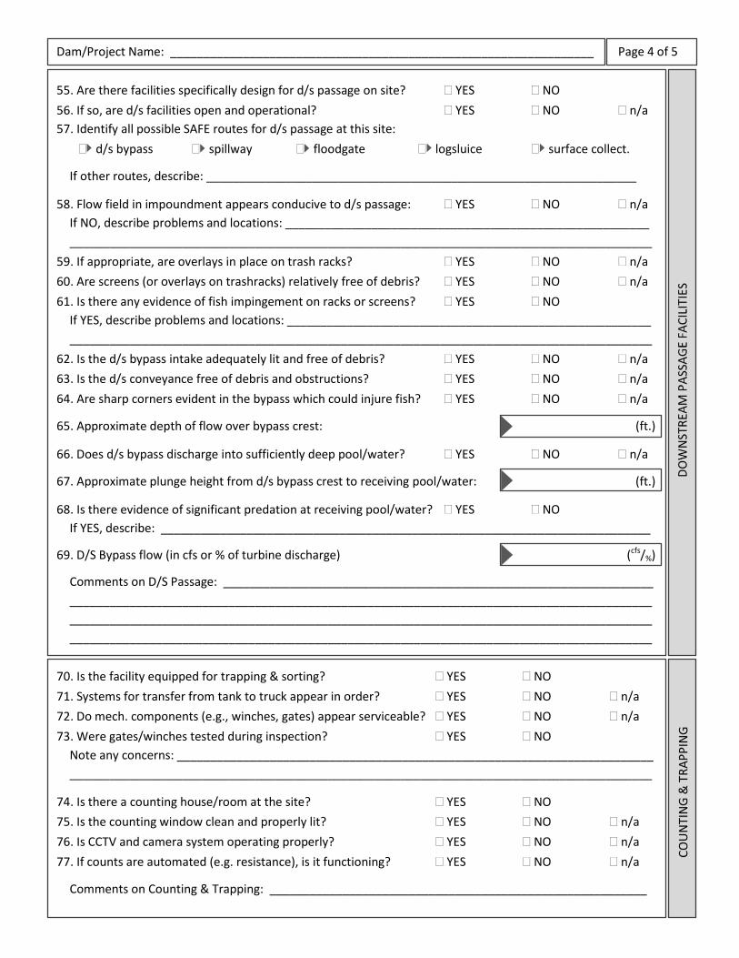
Dam/Project Name: ________________________________________________________________ Page 4 of 5
55. Are there facilities specifically design for d/s passage on site? YES NO
56. If so, are d/s facilities open and operational? YES NO n/a
57. Identify all possible SAFE routes for d/s passage at this site:
d/s bypass spillway floodgate logsluice surface collect.
If other routes, describe: _________________________________________________________________
58. Flow field in impoundment appears conducive to d/s passage: YES NO n/a
If NO, describe problems and locations: _______________________________________________________
________________________________________________________________________________________
59. If appropriate, are overlays in place on trash racks? YES NO n/a
60. Are screens (or overlays on trashracks) relatively free of debris? YES NO n/a
61. Is there any evidence of fish impingement on racks or screens? YES NO
If YES, describe problems and locations: _______________________________________________________
________________________________________________________________________________________
62. Is the d/s bypass intake adequately lit and free of debris? YES NO n/a
63. Is the d/s conveyance free of debris and obstructions? YES NO n/a
64. Are sharp corners evident in the bypass which could injure fish? YES NO n/a
65. Approximate depth of flow over bypass crest: (ft.)
66. Does d/s bypass discharge into sufficiently deep pool/water? YES NO n/a
67. Approximate plunge height from d/s bypass crest to receiving pool/water: (ft.)
68. Is there evidence of significant predation at receiving pool/water? YES NO
If YES, describe: __________________________________________________________________________
69. D/S Bypass flow (in cfs or % of turbine discharge) (cfs/%)
Comments on D/S Passage: _________________________________________________________________
________________________________________________________________________________________
________________________________________________________________________________________
________________________________________________________________________________________
70. Is the facility equipped for trapping & sorting? YES NO
71. Systems for transfer from tank to truck appear in order? YES NO n/a
72. Do mech. components (e.g., winches, gates) appear serviceable? YES NO n/a
73. Were gates/winches tested during inspection? YES NO
Note any concerns: ________________________________________________________________________
________________________________________________________________________________________
74. Is there a counting house/room at the site? YES NO
75. Is the counting window clean and properly lit? YES NO n/a
76. Is CCTV and camera system operating properly? YES NO n/a
77. If counts are automated (e.g. resistance), is it functioning? YES NO n/a
Comments on Counting & Trapping: _________________________________________________________

Dam/Project Name: ________________________________________________________________ Page 5 of 5
78. Is there an eel pass on site? YES NO n/a
79. If YES, what is the type of eel pass:
volitional ramp (TW to HW) permanent ramp & trap/lift temporary ramp & bucket
80. Describe the eel pass substrate media type:
stud (peg) bristle geotextile mat other: _______________________
81. Is the eel pass currently operating (i.e., wetted and installed)? YES NO n/a
Identify the water source (i.e., gravity, pump): __________________________________________________
82. Is the media clean of debris and watered throughout? YES NO n/a
Describe depth of flow and adequacy of attraction: _____________________________________________
Comments on Eel Pass: ____________________________________________________________________
________________________________________________________________________________________
OBSERVATIONS ON THE PRESENCE AND/OR MOVEMENT OF FISH DURING INSPECTION:
GENERAL COMMENTS:
RECOMMENDATIONS:
Version 6/3/2013. Fishway Inspection Guidelines, TR-2013-01. For updates or suggested revisions, contact [email protected]

Appendix C
Federal Interagency Nature-like Fishway
Passage Design Guidelines for Atlantic Coast Diadromous Fishes
Technical Memorandum
Federal Interagency Nature-like Fishway Passage Design Guidelines for
Atlantic Coast Diadromous Fishes
May 2016

i
Technical Memorandum Federal Interagency Nature-like Fishway Passage Design Guidelines
for Atlantic Coast Diadromous Fishes
May 2016
James Turek1, Alex Haro2, and Brett Towler3
1NOAA National Marine Fisheries Service, Narragansett, RI 2U.S. Geological Survey S.O. Conte Anadromous Fish Research Center, Turners Falls, MA and
3U.S. Fish and Wildlife Service, Hadley, MA
Abstract: The National Marine Fisheries Service (NMFS), the U.S. Geological Survey (USGS) and the U.S. Fish and Wildlife Service (USFWS) have collaborated to develop passage design guidance for use by engineers and other restoration practitioners considering and designing nature-like fishways (NLFs). The primary purpose of these guidelines is to provide a summary of existing fish swimming and leaping performance data and the best available scientific information on safe, timely and effective passage for 14 diadromous fish species using Atlantic Coast rivers and streams. These guidelines apply to passage sites where complete barrier removal is not possible. This technical memorandum presents seven key physical design parameters based on the biometrics and swimming mode and performance of each target fishes for application in the design of NLFs addressing passage of a species or an assemblage of these species. The passage parameters include six dimensional guidelines recommended for minimum weir opening width and depth, minimum pool length, width and depth, and maximum channel slope, along with a maximum flow velocity guideline for each species. While these guidelines are targeted for the design of step-pool NLFs, the information may also have application in the design of other NLF types being considered at passage restoration sites and grade control necessary for infrastructure protection upstream of some dam removals, and in considering passage performance at sites such as natural bedrock features. How to cite this document: Turek, J., A. Haro, and B. Towler. 2016. Federal Interagency Nature-like Fishway Passage Design Guidelines for Atlantic Coast Diadromous Fishes. Interagency Technical Memorandum. 46 pp. Disclaimer: The efficacy of any fish passage structure, device, facility, operation or measure is highly dependent on local hydrology, target species and life history stage, barrier orientation, and a myriad of other site-specific considerations. The information provided herein should be regarded as generic guidance for the design of NLFs for the Atlantic Coast of the U.S. The guidelines described are not universally applicable and should not replace site-specific recommendations, limitations, or protocols. This document provides generic guidance only and is not intended as an alternative to proactive consultation with any regulatory authorities. The use of these guidelines is not required by NMFS, USFWS or USGS, and their application does not necessarily imply approval by the agencies of any site-specific design.

ii
Table of Contents Introduction……………………………………………………………………………………………………………………………….1 Rationale for Passage Guidelines……………………………………………………………………………………………….2 Existing Fish Passage Design Criteria and Guidance……………………………………………………………………4 Federal Interagency Guidance with Science-Based Application………………………………………………….5 Target Species……………………………………………………………………………………………………………………………5 Run Timing and Passage Flows…………………………………………………………………………………………………..6 Body Morphology, Swimming and Leaping Capabilities and Behaviors………………………………………7 Federal Interagency Passage Design Guidance…………………………………………………………………………..9 General Design Rationale…………………………………………………………………………………………………………..9 Species-Specific Rationales………………………………………………………………………………………………………19 References……………………………………………………………………………………………………………………………….39
List of Figures Figure 1. Plan view, cross section, and profile illustrations of physical features and nominal measures relating to passage design guidelines for a typical boulder step-pool fishway……………9 Figure 2. Captioned photographs of constructed nature-like fishways (NLFs) for passage by Atlantic coast diadromous fishes……………………………………………………………………………………………..18
List of Tables Table 1. Atlantic coast diadromous fish species, common and scientific names………………………...6 Table 2. Summary of design guidelines for NLFs and related to swimming capabilities and safe, timely and efficient passage for Atlantic coast diadromous fish species…………………………………..17
1
Introduction Diadromous fishes spend portions of their lives in marine, estuarine and freshwater environments and migrate great distances throughout their life cycles. All diadromous fish species require unimpeded access between their rearing and spawning habitats. Diadromous fishes that use freshwater rivers and streams of the Atlantic Coast of the U.S. as spawning habitats include a diverse anadromous species assemblage, and the catadromous American eel (Anguilla rostrata) which spends much of its life in freshwater rearing habitat with adults out-migrating to spawn in the Sargasso Sea. These fishes deliver important ecosystem functions and services by serving as forage for higher trophic-level species in both marine and freshwater food webs (Collette and Klein-MacPhee 2002; Ames 2004; McDermott et al. 2015) and providing an alternative prey resource (i.e., prey buffer benefitting other species) to predators in estuaries and the ocean (Saunders et al. 2006). In rivers and streams, services provided by this diadromous fish assemblage include relaying energy and nutrients from the marine environment (Guyette et al. 2013),transferring energy within intra-species life stages in streams (Weaver 2016), providing benthic habitat nutrient conditioning and beneficial habitat modification (Brown 1995; Nislow and Kynard 2009; West et al. 2010), serving as hosts to disperse and sustain populations of freshwater mussel species (Freeman et al. 2003; Nedeau 2008), and enhancing stream macro-invertebrate habitat (Hogg et al. 2014). Diadromous fishes are also recognized in contributing significant societal values. Historically, Native Americans, European colonists, and post-settlement America relied heavily on these species as sources of food and for other uses (McPhee 2003). Many of these diadromous fish species are highly valued in supporting commercial and recreational fisheries, with some species prized as sportfish and/or food sources including culinary delicacies (Greenberg 2010). They also contribute to important passive recreational opportunities where people can observe spring fish runs, learn about their life histories, and appreciate these migratory fishes and their key roles in riverine, estuarine and marine ecosystems (Watts 2012). Many populations of Atlantic Coast diadromous fishes have been in serious decline for decades due to multiple factors including hydro-electric dams and other river barriers preventing access to spawning and rearing habitats, water and sediment quality degradation, overharvesting, parasitic infestations and other fish health effects, body injuries due to boat strikes and other human-induced impacts (Limburg and Waldman 2009; Hall et al. 2011; Waldman 2014). Shortnose sturgeon (Acipenser brevirostrum), Atlantic salmon (Salmo salar), and Atlantic sturgeon (Acipenser oxyrinchus oxyrinchus) (NMFS 1998, 2009, 2013a) have been designated as endangered under the Endangered Species Act (ESA) (Atlantic sturgeon are currently listed as threatened in the Gulf of Maine). American eel were recently considered for listing under the ESA (USFWS 2011, 2015) and are currently designated as a Species of Concern. Both alewife (Alosa pseudoharengus) and blueback herring (Alosa aestivalis) were designated as Species of Concern in 2006 (NMFS 2006), and NMFS was petitioned in 2011 to list both as ESA species. NMFS completed its review for the candidate ESA listing in 2013 and determined that listing either river herring species was not warranted as either threatened or endangered. NMFS continues to collect and assess monitoring data on the status of populations and abundance

2
trends of and threats to each river herring species (NMFS 2013b). Rainbow smelt (Osmerus mordax) were also previously designated by NMFS as a Species of Concern (NMFS 2007). To address these precipitously declining diadromous fish populations, pro-active restoration has been implemented by many agencies and non-governmental organizations to help restore diadromous fish runs by removing dams and other barriers, installing technical and nature-like fishways, or a combination of these passage restoration alternatives. Improving habitat access through dam removal and other measures may also contribute to diadromous species recolonizing historic freshwater habitats and increasing abundance and distribution of target species locally (Pess et al. 2014). Federal regulatory programs also seek to minimize upstream and downstream mortality of diadromous fishes passing hydro-electric dams or other river and stream barriers by requiring mitigative passage measures. The NMFS and USFWS have well-established programs to address diadromous restoration by providing funds for and/or technical assistance in the planning, design and implementation of fish passage restoration. Both NMFS and USFWS along with USGS seek to advance engineering design and technology in providing safe (from both physical injury and predator avoidance), timely, and effective upstream and downstream passage for all diadromous species targeted for restoration. At many passage barrier sites, complete removal of the obstruction presents the best alternative for restoring diadromous fish passage and watershed populations. For sites where barriers cannot be fully removed or modified, other passage alternatives can be considered. Nature-like fishways (NLFs) include a wide variety of designs such as step-pools, roughened ramps, rock-arch rapids, rocky riffles, and cross vanes which are typically constructed of boulders, cobble, and other natural materials to create diverse physical and hydraulic conditions providing efficient passage to multiple species including migratory and resident fish assemblages. NLFs also provide greater surface roughness and flow complexity than typical technical (or structural) fishways (e.g., Denil, steep-pass fishways), creating attractive flow cues to passing fish. Interstitial spaces and surface irregularities associated with NLFs also provide cover and spawning microhabitats, which may be particularly important in watersheds where these specific habitats are limited. The use of natural materials in NLFs such as fieldstone boulders and cobble is also beneficial in lessening the likelihood of fish injury from sharp-edge structures such as those typically associated with structural fishways. NLF designs such as partial or full-river width or bypass channels around barriers can result in effective passage if appropriately designed and constructed for passing fish over a wide range of flows throughout the anticipated seasonal run period for a target species or run periods for targeted fish species assemblage. Rationale for Passage Guidelines Fish passage guidelines contribute to best design practices, promote design consistency, and facilitate time and cost-efficiency and quality in engineering design of NLFs and related passage supporting ecological restoration of river systems. NMFS, USGS and USFWS initiated a collaborative effort in 2010 to compile and review existing information from published journals,
3
reports and other unpublished literature on body dimensions and the swimming and leaping capabilities of 14 Atlantic Coast diadromous fish species, and passage and hydraulic functioning of existing fishways. Published data on critical swim speed for each species were also secured, when available. NMFS subsequently organized and held a technical workshop including fish passage biologists and engineers from USGS, USFWS and state agencies experienced with diadromous fish passage in the Northeast region to discuss knowledge and experiences in species passage success and challenges. Subsequent federal agency meetings were held and follow-up consultations were made with professionals from state agencies, academia, and private industry to secure supplemental information on the biology of these target species and their experience with and data available for or analysis of fish swimming performance and/or passage evaluation of the Atlantic Coast diadromous fish species. Compiling and assessing species data and information from expert knowledge and field and flume laboratory experiences, NMFS, USGS and USFWS applied the collective dataset in developing science-based guidelines when fish swimming and leaping data were available, or best professional judgment when scientific data were limited or unavailable. Compiled information includes the ranges in body length and depth for each of the 14 target diadromous species, to derive body depth-to-total length ratios. These data were then applied in developing a set of six dimensional guidelines for designing passage openings and resting pools. To date, swim speed data from controlled respirometer experiments are available for 10 of the 14 species. Swim data from controlled open-channel swimming flume experiments were available for 8 of the 14 species (data for shortnose sturgeon and Atlantic salmon from USGS Conte Laboratory open flume are forthcoming). Swimming performance data from both respirometer and open-channel swimming flume research was then used to derive maximum through-weir velocity guidelines for each species. Where performance data for a species are minimal, more conservative estimates have been applied in developing the guidelines. The rationales for the guidelines presented in this document include published references or other source of information, as indicated; otherwise, guidelines presented herein are based on best professional judgment. These guidelines are primarily for purposes of informing the design of NLFs, and in particular, nature-like, step-pool fishways that include resting pools formed by boulder weirs with passage notches specifically designed for the intended target species. One or more of these passage guidelines may also have application to other types of NLFs. These guidelines may also be considered for application in evaluating potential passage alternatives at low-head dams and other barrier sites (e.g., flow diversion and gauging station weirs) and in designing grade control structures upstream of potential dam removals to improve fish passage and/or to protect upstream infrastructure (e.g., bridges and utilities buried in channel bed and bordering floodplain). At some dam removal sites, passage design features may be required upstream of barrier removals to take into account channel bed adjustments which may otherwise result in exposure of and damage to existing infrastructure and/or re-exposure of natural bedrock features. These guidelines may also have application for assessing the likelihood of safe, timely and effective passage at existing natural barriers considered in the context of passage restoration throughout a watershed. As additional studies on fish swimming performance and

4
fish passage effectiveness are completed, these guidelines may be subject to further updates and revisions. Existing Fish Passage Design Criteria and Guidance During development of these guidelines, a thorough review was conducted to evaluate other efforts in establishing criteria for fish passage design. To date, a science-based application of fish body morphology, swimming and leaping capabilities, and behavior for passage design has been limited, with most early studies and publications focused on salmonid passage through culverts in the U.S. Pacific Northwest. Bell (1991) presents a synopsis of biological requirements of a limited number of fish species which are then applied to developing biological design guidance including swimming speeds of both juvenile and adult life stages; the published swimming speeds are based primarily on limited and non-standardized experimental methods. Clay (1995) provides an overview of fishway types and examples of installed technical fishways on the Atlantic Coast of North America and elsewhere, with passage guidance that targets hydraulics over weirs, through slots or orifices, and in resting pools which are related to varying fish swims speeds. Beach (1984) and Pavlov (1989) note that body length and water temperature influence swim speeds which in turn help to define passage design guidance. The Food and Agriculture Organization (FAO 2002) released guidance on European upstream fish passage design, as a follow-up to a 1996 publication prepared by the German Association for Water Resources and Land Improvement (‘DVWK’). The FAO document addresses general fish body size and swim speed of a number of European species, along with designated river “fish zones” in which diadromous and resident fishes are found. The FAO guidance also addresses both nature-like and technical fishways, and general design and detailed guidelines for, and completed examples of (e.g., design dimensions, construction materials and fishway sizes) nature-like fishways. The FAO document is the first guidance for nature-like fishway design, taking into account the swimming and leaping capabilities of fishes. The Maine DOT (2008) presents both a fish passage policy and design guidelines for passage of diadromous and freshwater fishes through culverts including a minimum-depth guideline applied to low flows, and a maximum-flow velocity guideline based primarily on body-length derived from sustained swimming speeds of target species. The Maine DOT guidance does not address design guidance for fishways. Similar culvert design guidance was released by the Vermont DFW (2009) discussing Atlantic salmon and resident freshwater species biometric and swimming information for passage design including maximum jump height, and a minimum passage water depth of 1.5 times the maximum body depth of the target species. Other states (Washington, California) have released guidance materials for anadromous fish passage design of culverts (Bates et al. 2003, California Department of Fish and Game 2009). The guidelines for velocity and jump height thresholds in these design documents are typically intended to provide passage conditions for the weakest fishes and smallest individuals of each species, while the minimum passage depth guideline for a species is based on the largest-sized fish expected to pass.

5
There are several sources of passage design for the construction of nature-like fishways. NMFS’ Northwest Region provides guidance for passage specifically for Pacific salmonids (primarily genus Oncorhynchus) (NMFS 2008, updated 2011), with fish biological requirements and specific design guidelines (prescriptive unless site-specific, biological rationale is provided and accepted by NMFS) and general guidelines (specific values or range in values that may vary when site-specific conditions are taken into consideration) to address a variety of passage types including both technical fishways and nature-like ramps. Aadland (2010) addresses dam removal and nature-like structures for achieving fish passage targeting Mid-Western region warm and cool water fish assemblages, with nature-like fishways serving as features to emulate natural rapids and providing a range of passage conditions and in-fishway habitats benefitting diverse fish assemblages with varying species’ swimming capabilities. The document also presents a review of engineering design practices for rock ramp, rock arch rapids and bypass channels. The U.S. Department of Interior’s Bureau of Reclamation (Mooney et al. 2007) provides detailed guidelines for nature-like rock ramp design, although species-specific body metrics and swimming and leaping requirements are not addressed in detail. This existing published passage guidance literature contributes valuable input on how criteria and guidelines have been developed for a number of fish species and variety of fish assemblages and river systems. Conversely, none of the guidelines are targeted specifically for Atlantic Coast diadromous fishes which each have specific body morphology and swimming and leaping capabilities. NMFS, USGS and USFWS thus seek to provide a set of guidelines addressing this diadromous fish assemblage for use by passage restoration practitioners. Federal Interagency Guidance with Science-Based Application As noted above, the federal interagency team reviewed and evaluated relevant published journal articles, reports and gray literature, summarized and selected more recent data gained through controlled experiments (e.g., USGS Conte Anadromous Fish Laboratory and other open channel flumes), utilized past performance data from constructed NLFs (primarily in the Northeast), and advanced hydraulic formulae pertinent to nature-like fishway design (e.g., SMath model; See Towler et al. 2014) to develop these science-based guidelines. These guidelines are intended to benefit passage design professionals with information to provide safe, timely and effective passage for Atlantic Coast diadromous fish species targeted in using step-pool and other NLFs. Target Species Biological information has been compiled and evaluated for fourteen diadromous species in developing these passage design guidelines. The species addressed in this memorandum include species endemic to the Atlantic Coast. The species are listed according to an evolutionary taxonomic hierarchy (Table 1). While not currently addressed by this document, other anadromous (e.g., sticklebacks), amphidromous, and/or potamodromous fish species may be added in future interagency updates, as more research-based swimming and leaping performance data become available and are evaluated.
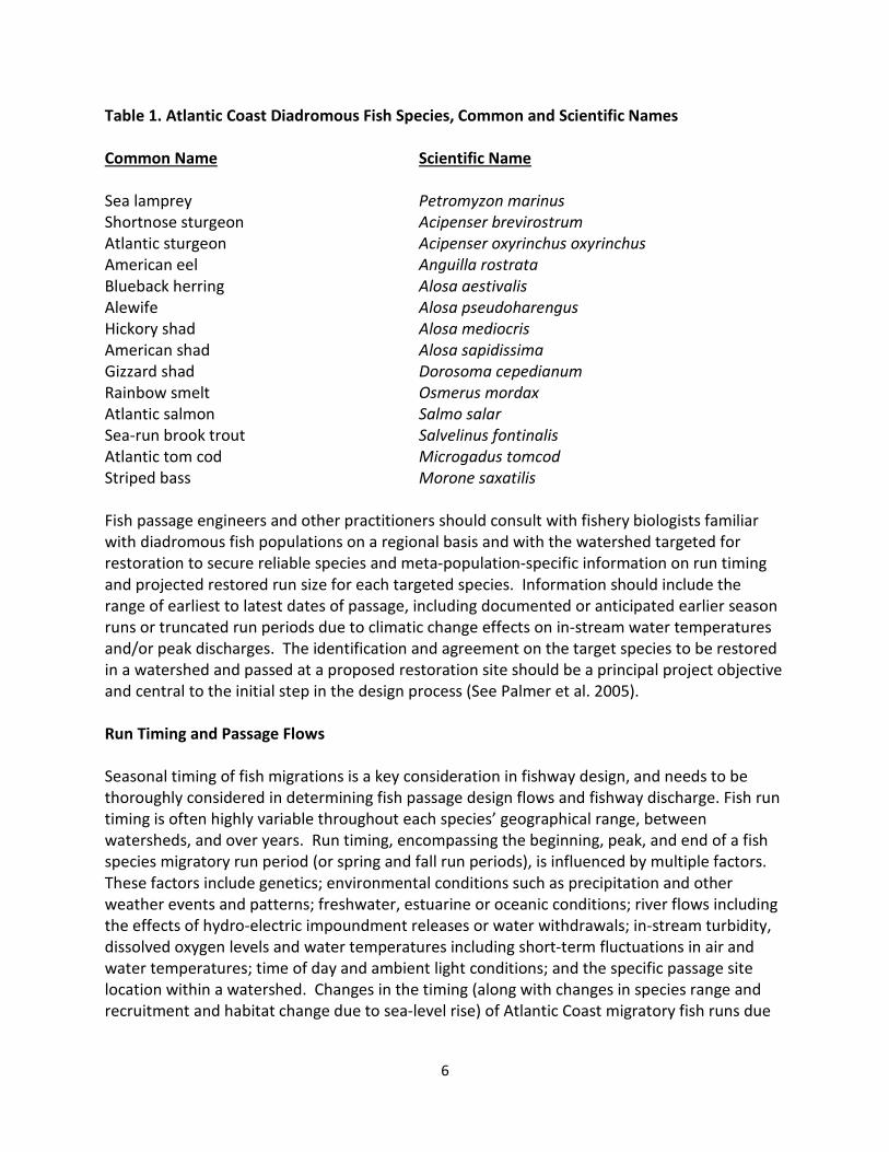
6
Table 1. Atlantic Coast Diadromous Fish Species, Common and Scientific Names Common Name Scientific Name Sea lamprey Petromyzon marinus Shortnose sturgeon Acipenser brevirostrum Atlantic sturgeon Acipenser oxyrinchus oxyrinchus American eel Anguilla rostrata Blueback herring Alosa aestivalis Alewife Alosa pseudoharengus Hickory shad Alosa mediocris American shad Alosa sapidissima Gizzard shad Dorosoma cepedianum Rainbow smelt Osmerus mordax Atlantic salmon Salmo salar Sea-run brook trout Salvelinus fontinalis Atlantic tom cod Microgadus tomcod Striped bass Morone saxatilis Fish passage engineers and other practitioners should consult with fishery biologists familiar with diadromous fish populations on a regional basis and with the watershed targeted for restoration to secure reliable species and meta-population-specific information on run timing and projected restored run size for each targeted species. Information should include the range of earliest to latest dates of passage, including documented or anticipated earlier season runs or truncated run periods due to climatic change effects on in-stream water temperatures and/or peak discharges. The identification and agreement on the target species to be restored in a watershed and passed at a proposed restoration site should be a principal project objective and central to the initial step in the design process (See Palmer et al. 2005). Run Timing and Passage Flows Seasonal timing of fish migrations is a key consideration in fishway design, and needs to be thoroughly considered in determining fish passage design flows and fishway discharge. Fish run timing is often highly variable throughout each species’ geographical range, between watersheds, and over years. Run timing, encompassing the beginning, peak, and end of a fish species migratory run period (or spring and fall run periods), is influenced by multiple factors. These factors include genetics; environmental conditions such as precipitation and other weather events and patterns; freshwater, estuarine or oceanic conditions; river flows including the effects of hydro-electric impoundment releases or water withdrawals; in-stream turbidity, dissolved oxygen levels and water temperatures including short-term fluctuations in air and water temperatures; time of day and ambient light conditions; and the specific passage site location within a watershed. Changes in the timing (along with changes in species range and recruitment and habitat change due to sea-level rise) of Atlantic Coast migratory fish runs due
7
to climate change have been identified in a number of locations (Huntington et al. 2003; Juanes et al. 2004; Fried and Schultz 2006; Ellis and Vokoun 2009; Wood and Austin 2009). For purposes of this document, the federal agencies recommend that a NLF be designed to function in providing passable conditions over a range of flows from the 95% to 5% flow exceedance during the targeted species migratory run period or the collective run periods for multiple target species. The range of river flows used to inform the design of a fishway can be graphically represented by a flow duration curve (FDC). The FDC should be based on the historic probability of flows at the site, or scaled to the project site from an appropriately similar reference site. Active, continuously operated USGS stream gages typically provide the most reliable and complete record of flows for rivers and streams in the U.S. To reasonably estimate future conditions, a sufficiently long period of record (POR) is required. In general, a POR of 10 to 30 years is recommended. Furthermore, the use of post-1970 flow data is preferred to account for documented increasing peak flows over time due to climatic change (See Collins 2009). Additional considerations that influence the length of the POR may include, but are not limited to, gauge data availability, alterations in upstream water management, and changing trends in watershed hydrology. Body Morphology, Swimming and Leaping Capabilities and Behaviors Diadromous fishes vary greatly in body shape and size and swimming and leaping capabilities. General body size in fish populations may be affected by genetics, environmental conditions and other factors. Historic fishery catch data indicate decreasing trends in average body size of anadromous fishes that have resulted from overharvesting and natural mortality factors (ASMFC 2012; Waldman 2014; Waldman et al. 2016). Fish body shape and anatomy are determinants of how a fish moves, functions, and adapts to its river environment. Fish body size also affects swimming performance, and swimming ability is largely a function of fish biomechanics and hydrodynamics of its environment (Castro-Santos and Haro 2010). Larger fish have proportionally more propulsive area and a larger muscle mass, and are thus able to move at greater absolute speeds (i.e., the absolute distance through water covered over time). For example, a 10-cm long striped bass swimming at 5 body lengths per second will move through the water at 50 cm per second, while a 50 cm striped bass swimming at 5 body lengths per second will move through the water at 250 cm per second. Larger fish may also have a greater likelihood of injury from coming in contact with boulders or other structures. Fish age, physiological state, and environmental conditions such as water temperature, are additional factors influencing fish movement, behavior (e.g., propensity to pass in schools or groups), passage efficiency, and ultimately passage effectiveness. In addition to swimming biomechanics, fish exhibit an equally important variety of behavioral responses to their physical and hydraulic environment such as motivation, attraction, avoidance, orientation, maneuvering, station-holding, depth selection, and schooling. In particular, schooling behavior occurs with some species and should be accommodated in fish passage design (e.g., passage opening dimensions and/or multiple openings within each boulder weir). Although basic behaviors of fish have been studied in both laboratory and field
8
environments, only a modest number of behavioral studies have directly addressed fish passage. Most behavioral observations in reference to passageways have been a secondary outcome of passage evaluation studies, where study objectives or experimental designs were not focused on the evaluation of the causes of the behavioral responses. Understanding the swimming capability of a target species is critical to designing fish passage sites. Swimming performance depends greatly on the relationship between swim speed and fatigue time. At slower speeds, fish can theoretically swim indefinitely using aerobic musculature. Once swim speed exceeds a certain threshold, fish begin to recruit different muscle fibers that function without using oxygen. This condition is noticeable by the onset of burst-and-coast swimming – a kinematic shift, whereby fish use both aerobic and anaerobic muscle fibers to power locomotion (Beamish 1978). Anaerobic muscle fibers can only perform for brief periods before running out of metabolic fuel; thus, high-speed swimming results in fatigue and is usually of very short duration. This physiological condition affects potential passage by a fish through high-velocity zones in rivers and fishways. In general, fish swim at speeds requiring anaerobic metabolism infrequently, given the energetic demands of this swimming mode. Three operationally-defined swimming modes exist in fish: sustained, prolonged, and sprint speeds. Sustained swimming occurs at low or sustained speeds that are maintained for greater than 200 minutes (Beamish 1978). Prolonged swimming occurs at speeds that fish can maintain for 20 seconds to 200 minutes, and sprint swimming can only be maintained for periods of less than 20 seconds. Determining these swim modes and the critical swim speed – the threshold at which a fish changes from sustained to prolonged swim speeds (Ucrit) is challenging. For many species, quantitative measures of these swimming modes are unknown, and only a few fish species have been comprehensively evaluated for all three modes. Laboratory respirometer experiments are used to determine the thresholds for a species’ swim speeds, but these tests tend to underestimate maximum swimming speed, and may therefore, be limited in accurately measuring burst-speed swimming. Determining burst swimming speeds is usually conducted in open channel flumes, but these experiments can also be biased by fish behavior, stress, or motivation (Webb 2006). Nonetheless, open channel flume studies usually provide better estimates of true swimming performance than results from studies of fish in respirometers, and are the preferred data source for determining fish swimming capabilities and for establishing passage guidelines presented in this document. Existing experimental swim data are also limited in terms of the size range of fish, species life history stage, and experimental water temperatures. Swimming capabilities of fish may also be significantly influenced by turbulence, air entrainment, or other hydraulic/physical factors that influence swimming efficiency and fish motivation. Leaping (or “jumping”) is another component of swimming performance that must be considered in designing and assessing fish passage sites. Leaping height is positively correlated with swimming speed and water depth of the pool from which fish leap. Larger or deeper pools allow higher swimming velocities (i.e., a “running start”) to be attained before leaping. Larger

9
fish tend to have greater absolute leaping heights, but also require corresponding increased depths from which to leap. Leaping behavior can be initiated by the fall or plunging flow into a pool creating strong submerged water jets which serve as a stimulus and orientation cue for the direction and speed of an ensuing leap. While salmonids are known to leap during their upstream passage, many non-salmonid fish species are poor leapers or do not leap at all, being physically restricted by body morphology or maximum swimming speed, or more commonly, being behaviorally reluctant to do so. Leaping increases the potential risk of injury or stranding. Typically, leaping or sprint swimming behavior are expressed only when other behaviors are ineffective in passing a velocity or structural barrier. The design of fishways should present conditions that minimize leaping behaviors. Federal Interagency Passage Design Guidelines The following are key passage design guidelines that have been identified by the federal interagency team for application to passage of Atlantic Coast diadromous species, and for some species, more discrete guidelines according to life stage/body size categories for the species. These guidelines may be updated by the agencies as additional flume experiments, respirometer and other laboratory studies, and/or field research are completed and results become available that address the physiological and/or behavioral requirements, swimming and leaping capabilities, and passage efficiency of these diadromous fishes and/or other migratory species. General Design Rationale This section describes body morphologic dimensions which are determinants of passage, followed by a set of seven design guidelines for each species based on these fish biometrics, plus a maximum velocity criterion based on each species swimming capability. Schematic illustrations are provided in Figure 1 to accompany and help explain the descriptions of these passage guidelines. Some variables labeled in the graphics are not passage guidelines, but relate to the guidelines. Following the set of passage guidelines descriptions, we present Table 2 which summarizes the passage guidelines for each of the 14 Atlantic Coast diadromous species, including two length categories for American eel and smaller-sized salmonids; and the basis for, and rationales used in developing this set of guidelines for each of the 14 target fish species. Figure 1. Plan view (A), cross section (B), and profile (C) illustrations of physical features and nominal measures relating to passage design guidelines for a typical boulder step-pool type fishway. Note: Schematic profile includes variables that relate to passage guidelines including: Q= flow, tw= thickness of boulder weir, D= hydraulic drop, Pw= height of rock weir crest, Hw= head over the rock weir, Hg= gross head between headpond and tailwater water surface elevations, and Lt= total length of fishway.

10
Fish Body Morphology (TLmin, TLmax, BD/TL Ratio): Maximum and minimum total lengths (TLmax
and TLmin, respectively) and body depth (BD) to total length ratio (BD/TL) for each species were determined to the nearest cm from values published in the literature for diadromous fishes in the Atlantic Coast region. For species with limited or no published data available, unpublished data from recent field investigations were used (Refer to sources cited in species rationales section). Pool Dimensions Dimensions of a pool are based on the need to create full- or partial-width channels and pools or bypass channels with pools of sufficient size to serve as resting areas for the target fish species and provide for their protection from predators during passage. Larger fish or species that school in large numbers (hundreds to thousands) require wider, deeper, and longer pools.

11
The anticipated total run size of the target species and co-occurring species assemblages also need to be thoroughly considered in dimensioning pools. As a guideline, pool dimensions should also be scaled relative to the size of the stream or river channel and existing pool conditions in nearby unaltered reach or reaches of the study river as a reference, and river flows for the specific design reach. This scaling guideline should be applied regardless of whether the design involves a full or partial width of the stream or river targeted for passage restoration, or is a nature-like bypass channel around a dam or other passage barrier that cannot be removed or modified. Each of the following dimensions should be considered in NLF design:
Minimum Pool Width (WP): For full river-width structures, minimum pool width will vary depending on the size of the river or stream channel. For bypass channels, pool width will depend on maximum design width of the bypass, taking into account the proportion of the river flows used to design safe, timely and effective passage through the bypass during the full range of fish run flows at the subject river reach. To maximize energy dissipation, pool volume, and available resting areas, pool widths should generally be made as wide as practicable. Minimum Pool Depth (dP): In general, pools should be sufficiently deep to serve as resting areas, allow for maneuverability, accommodate deep-bodied and schooling species, and offer protection from terrestrial predators. For small streams (e.g., site with watershed area <5 mi2), the stream/river channel scaling guideline may be difficult to achieve, and the project design team should assess normal pool depth range in nearby reference reach(es) during the fish passage season. For downstream passage, a minimum depth of pools is needed to provide safe passage of fish and prevent injury or stranding of fish passing over a weir or through a weir opening, especially during low-flow outmigration conditions. Height of the fall as well as body mass of each species needs to be taken into account to minimize the potential for injury to out-migrating fish. For all species, a formula for minimum pool depth was derived which includes a minimum depth of 1 ft, plus 3 body depths, plus one additional body depth as a bottom buffer (to accommodate bottom unconformities and roughness); thus, dp = 1 ft + 4 BD. Final values of the dp guideline have been rounded up from the calculated value to the nearest 0.25 ft. Minimum Pool Length (LP): Pool length dimensions follow design guidelines similar to the pool widths, but also depths (i.e., maximize energy dissipation, pool volume and available resting areas; accommodate fish body size(s), run size(s), and resting and schooling behaviors). More importantly, pool length also determines overall slope of the fishway for a given drop per pool, so slope must be taken into account when determining minimum pool length (as well as the number of pools for a given design and overall drop). Refer to the Maximum Fishway Channel Slope (S0) criterion which takes into account both pool length and drop-per-pool.
12
Minimum Weir Opening Width (WN): The weir opening width (i.e., weir notch lateral length) relative to fish passage is based on providing a primary passage opening wide enough to accommodate fish body size and swimming mode and schools of upstream migrating target species adults. For sea lamprey and American eel (anguilliform swimmers), WN equals 2 times the tailbeat amplitude (values from published literature) for the largest sized individual. For sturgeons, which possess a relatively wide body with broad pectoral fins, WN equals 2 times the body width of the largest-sized individual, including maximum pectoral fin spread during passage. For all other target species, WN equaled 2 times the maximum total body length. Final values of WN were rounded up from the calculated value to the nearest 0.25 ft. The opening width should also be designed for downstream migrating fish that may be oriented obliquely to the flow in a worst-case condition, to minimize potential body contact with (and subsequent injury) the weir-opening sidewall boulders. Wide weir openings also facilitate location of and attraction to the weir opening by fish in broader river reaches and passage sites by providing a flow jet that spans a larger proportion of the total pool width. Weirs will optimally have multiple passage openings, particularly on larger rivers, with varying invert elevations to function over a range of river flows during the passage season(s) and to benefit multiple species with varying swimming capabilities. Conversely, the passage opening width needs to take into account the pool depth and hydraulics to accommodate the target species. For small streams with limited flows, the passage opening may need to be limited in width to maintain a minimum depth for passage due to very low flows over weirs, and in particular through a notch especially with lowest flows (e.g., flows <5 cfs) during the fish run period. Weirs should be properly designed such that modeled flows through a passage reach should result in submerged weirs or other grade control structures with passage openings, even during the lowest fish run flows. Such a design will result in streaming flow into a pool with water surface elevation at or above the upstream weir opening invert elevation, and preferably backwatering to the weir crest elevation. Minimum Weir Opening Depth (dN): Weir opening depths (i.e., weir notch) need to at least accommodate the full depth (vertical depth of body when swimming horizontally) of the body of the largest-sized target species, including extended dorsal and ventral fins to minimize potential for injury. We conservatively established dN as 3 times the body depth of the largest-sized individual, rounded up to the nearest 0.25 ft. Minimum depths allow freedom of swimming movements and assurance that propulsion and maneuverability by the tail and fins will allow maximum generation of thrust and the ability of fish to maneuver. If limited river flows during the passage season(s) are not a concern, greater passage opening water depth is preferred at locations where schooling fish, like American shad, are passing simultaneously or passing fish are at high risk to predation. Sufficient water depths are also needed to create a low-velocity bottom zone to facilitate ascent by bottom-dwelling or smaller, weaker-swimming species. The calculated low stream-flow for the target species run period is most critical to designing the weir opening dimensions and to ensure the minimum water depth guideline is attained. Thus,

13
depths of weirs, openings and other passageway features should be designed to accommodate minimum fish-run period flows and low-flow depths. This passage design need is most critical on small streams and watersheds where normal stream flow is limited (e.g., <20 cfs) and flow through a weir opening would be very limited (e.g., <2 cfs). Maximum Weir Opening Water Velocity (Vmax): The ability of fish to traverse zones of higher water velocity, particularly through passage openings, is dependent on motivation, physiological capability (sprint swimming speed), and size range of the target species, and the overall distance that the fish must swim through a high-velocity passage zone. For most weir openings in typical fishway designs, the distances and durations that fish must swim to make upstream progress is relatively short (i.e., tens of feet), so fish may be able to swim over weirs or through these openings at prolonged or brief sprint speeds resulting in minimal fatigue. The probability of fish passing upstream through velocity barriers at prolonged or sprint speeds can be calculated for some species based on known high-speed swimming performance or empirical high-speed swimming model data, particularly the critical swim speed for a species (e.g., Weaver 1965, McAuley 1996, Haro et al. 2004). Sprint swimming data, if available, are usually the best data to use to infer maximum weir opening water velocity. However, sprint swimming research has not been conducted and/or sprint swimming curves have not been developed for most Atlantic Coast diadromous fish species, in which case, alternative methods for determining maximum weir opening velocity were used for developing this guideline. The following rationale was used to determine Vmax for each species:
1. When sprint swimming data are available, then Umax = the sprint swimming speed sustained for 60 sec, for fish of minimum size (TLmin).
2. When no sprint swimming data are available, but critical swimming speed (Ucrit) values have been determined (i.e., from respirometer studies), then Umax = 2 times Ucrit for fish of minimum size (TL min).
3. When no swimming data are available, Umax is calculated for a nominal value of 5 BL/sec for subcarangiform swimmers or 3 BL/sec for anguilliform swimmers, for fish of minimum size (TL min).
4. The initial value of Umax was adjusted (if necessary) by assessing calculated Umax values within the context of other direct fish swimming observations of each species and known velocity barriers (if available; i.e., observed ability to pass a velocity barrier with known water velocity, or best professional judgment, based on experience).
5. Vmax = Umax, rounded down to the nearest 0.25 ft/sec. The Vmax applied in each project should be the value associated with the weakest swimming target species. The Vmax values presented herein for each species are specifically provided for the targeted species expecting to pass over a weir, through a weir opening or other short-distance high velocity zone and into an effective resting area. A Vmax value should not be misapplied as the guideline for the overall design or diagnostic evaluation of an entire fishway or fish passage reach, where passage length and time of passage would exceed the capability of the target species in sprint swimming mode to pass the site without available resting pools or

14
sites. Such an example may include a rock ramp nature-like fishway constructed at too steep a slope for the target species, and which lacks resting pools, large boulders, or other features providing adequate resting areas. Maximum Fishway Channel Slope (S0): The channel slope, S0, influences energy loss and water velocity over weirs, through weir notches, in pools, and around other in-stream features. In turn, velocity and energy dissipation influence fish behavior and passage efficiency. The friction slope, Sf, is the rate at which this energy is lost along the channel. In prismatic-shaped channels, uniform flow (i.e., flow that is unchanging in the longitudinal direction) occurs when S0 = Sf. In step-pool fishway structures, the average friction slope is equal to the ratio of hydraulic drop-per-pool, D, to pool length plus weir thickness, Lp + tw (Figure 1). Thus, quasi-uniform or “uniform-in-the-mean” flow is achieved in step-pool fishways when S0 and the average Sf are equal over the length of the fishway. In most cases, step-pool fishways are designed for this quasi-uniform condition to limit longitudinal flow development (e.g., accelerating flow) and ensure predictable hydraulic conditions in each pool and over each weir. Quasi-uniform flow establishes a relationship between S0 and Sf in step-pool structures; however, an additional constraint on S0 is necessary to safeguard against unacceptably steep fishway designs. Both the pool length and drop-per-pool criteria are based on a species’ need for adequate resting space and swimming capability, respectively. Fishway channel slopes based solely on quasi-uniform flow and a friction slope established by the recommended maximum D and minimum Lp may still result in excessive energy dissipation, propagation of velocity from pool to pool, and/or other undesirable conditions. Therefore, a maximum fishway channel slope, S0, is also recommended. These channel slopes presented herein (Table 1) are conservative estimates based on natural river gradients and sites known to be passable or populated by the target species. The reader is cautioned that these slope relationships and associated pool and hydraulic drop criteria create an over-determined system (i.e., more equations than unknowns). To avoid conflicting slope constraints, the following procedure is recommended:
1. Based on a species’ Vmax (Refer to Table 2, below), calculate an appropriate D; 2. Based on D and Lp (Table 2), estimate the friction slope, Sf; 3. If Sf ≤ channel slope S0 (Table 2), then set S0 = Sf and proceed;
If Sf > S0, then lengthen Lp or add pools to the design to reduce D (while ensuring minimum depth of flow criterion is also met ) until Sf < S0, and proceed.
Consider the following example for the passage of alewife over a step-pool structure: For this target species, a Vmax of 6 ft/sec is recommended (Table 2). To provide structural stability, a 3-ft wide rock weir is selected. Using this Vmax and tw, a hydraulic analysis results in a maximum drop-per-pool of D= 1.25 ft. For alewife as the target species, a minimum pool length of Lp = 10 ft is recommended (Table 2). This results in a friction slope, Sf = 0.092 which exceeds the specified maximum pool slope of S0 = 0.05 or 1:20 (Table 2). Accordingly, the geometry needs

15
to be revised to ensure the maximum channel slope criterion is met. The Lp must be increased, D must be decreased, or both until Sf ≤ S0. In general, consistent pool geometry is preferred, but may not be feasible for some passage sites. When site constraints necessitate pools of varying geometry, the procedure above should be applied, iteratively, to each pool-and-weir combination to ensure S0, Sf, and the other passage criteria are met.
The above methodology integrates species-specific biological criteria from Table 2 and engineering hydraulics. However, it is important to note that fishway geometry is also influenced by other site conditions and target fish species behavioral factors. Additional considerations include substrate stability, channel morphology, immovable boulders/ledge and other natural features that may further constrain the slope of the fishway. Excessively long pool length, which may otherwise meet slope criteria, may decrease motivation of a target species to pass, thus, compromising passage efficiency. As fish passage planning progresses from conceptual to final design, it is critical to verify these parameters with each design modification to ensure that criteria are still met for the weakest target species and over the greatest possible range of hydrologic conditions at the project site. Other Design Considerations: For moderate and large-sized rivers, multiple weir openings should be provided for safe passage by multiple target species and schools of a species that behaviorally pass in groups (e.g., American shad). The design should consider the diversity of the fish community present in the stream or river. Large rivers with greater spatial habitat diversity typically support a greater number of both resident and anadromous species, with large numbers of fishes seasonally passing upriver often during coincidental, overlapping spawning run periods. A diverse fish assemblage and large numbers of fish passing necessitate multiple passage openings, and benefitting from varying invert elevations and locations along the weir to account for changes in river flow, especially in larger rivers with a diverse fish assemblage and/or widely varying fish run flow range. Weaker-swimming species will use passage openings closer to the river edge and inside river bends where lower flow velocities occur. Weak-swimming species (e.g., minnows, darters) and some species life-stages (e.g., American eel elvers and yellow-phase juveniles) seek out low-velocity, near-bottom conditions not only for passage sites but often as habitat (Aadland 1993). Regarding passage at weirs, fish will preferentially pass through weir openings, rather than over weir crests. Fish preferentially use streaming flow through openings, as opposed to plunging flows passing over weirs and into resting pools which are often impassible for species with limited leaping capabilities. Although an in-line configuration of weir openings is preferred, primary openings along multiple weirs can be off-set in alignment to prevent propagation of increasing flow velocities through successive weirs or other grade control structures. Channel size and flow (e.g., bypass channels) should be referenced to both river size and projected run size of the target fish species or fish community assemblage. For example, nature-like bypass fishways sited on large rivers would need to be appropriately sized for flow

16
and run-size capacity. Fishways which are expected to support large runs of target species should include longer and deeper pools to provide sufficient resting areas to accommodate large numbers of fish during peak passage periods. Figure 2 provides examples of photographed NLF sites in the Northeast region targeted for passage by Atlantic coast diadromous fish species.

17
Table 2. Summary of design guidelines for NLFs and related to swimming capabilities and safe, timely and efficient passage for Atlantic Coast diadromous fish species. Note: units are expressed in both metric (cm) and English units (feet or feet/sec). See text for informational sources.
Species Minimum
TL (cm) Maximum
TL (cm)
Body Depth/ TL Ratio
Maximum Body Depth
(cm)
Minimum Pool/Channel
Width (ft)
Minimum Pool/Channel
Depth (ft)
Minimum Pool/Channel
Length (ft)
Minimum Weir
Opening Width (ft)
Minimum Weir
Opening Depth (ft)
Maximum Weir Opening
Water Velocity (ft/sec)
Maximum Fishway Channel
Slope TLmin TLmax BD/TL BDmax Wp dP Lp WN dN Vmax S0
Sea Lamprey 60 86 0.072 6.2 10.0 2.00 20.0 0.75 0.75 6.00 1:30
Shortnose Sturgeon 52 143 0.148 21.2 30.0 4.00 30.0 2.75 2.25 5.00 1:50
Atlantic Sturgeon 88 300 0.150 45.0 50.0 7.00 75.0 5.50 4.50 8.50 1:50
American Eel < 15 cm TL 5 15 0.068 1.0 3.0 1.25 5.0 0.25 0.25 0.75 1:20
American Eel >15 cm TL 15 116 0.068 7.9 6.0 2.00 10.0 0.75 1.00 1.00 1:20
Blueback Herring 20 31 0.252 7.8 5.0 2.00 10.0 2.25 1.00 6.00 1:20
Alewife 22 38 0.233 8.9 5.0 2.25 10.0 2.50 1.00 6.00 1:20
Hickory Shad 28 60 0.221 13.3 20.0 2.75 40.0 4.00 1.50 4.50 1:30
American Shad 36 76 0.292 22.2 20.0 4.00 30.0 5.00 2.25 8.25 1:30
Gizzard Shad 25 50 0.323 16.2 20.0 3.25 40.0 3.50 1.75 4.00 1:30
Rainbow Smelt 12 28 0.129 3.6 5.0 1.50 10.0 1.00 0.50 3.25 1:30
Atlantic Salmon 70 95 0.215 20.4 20.0 3.75 40.0 6.25 2.25 13.75 1:20
Sea Run Brook Trout 10 45 0.255 11.5 5.0 2.50 10.0 1.50 1.25 3.25 1:20
Juvenile Salmonid < 20 cm TL 5 20 0.250 5.0 5.0 1.75 10.0 1.25 0.50 2.25 1:20
Atlantic Tomcod 15 30 0.202 6.1 5.0 2.00 10.0 2.00 0.75 0.75 1:30
Striped Bass 40 140 0.225 31.5 20.0 5.25 30.0 9.25 3.25 5.25 1:30

18
Figure 2. Captioned photographs of nature-like fishways (NLFs) in the Northeast targeting passage of Atlantic coast diadromous fishes (Photo sources: J. Turek, M. Bernier)
Saw Mill Park step-pool fishway, Fields Pond step-pool fishway, Acushnet River, Acushnet, MA Sedgeunkedunk Stream, Orrington, ME
Kenyon Mill step-pool fishway, Homestead dam removal and NLF cross-vanes, Pawcatuck River, Richmond, RI Ashuelot River, West Swanzey, NH
Water Street tidal rock ramp, Lower Shannock Falls NLF weirs, Town Brook, Plymouth, MA Pawcatuck River, Richmond, RI

19
Species-Specific Rationales The following passage guidelines rationales for each species are based upon best professional judgment, unless otherwise noted by referenced published literature or other source(s). We applied our experiences with laboratory flume experiments and field observations, and queried other state and federal agency experts in fishery biology and/or fishway engineering design. We note that there is a general paucity of experimental research available, and substantial additional species information is required to verify or refine these guidelines. Sea Lamprey TLmin = 60 cm (Collette and Klein-MacPhee 2002) TLmax = 86 cm (USFWS Connecticut River Coordinator’s Office, unpub. data) Body Depth/TL Ratio = 0.072 (A. Haro, USGS; unpub. data) Minimum Pool/Channel Width: 10.0 ft The guideline is based on creation of pools large enough to serve as resting areas and protection from terrestrial predators. Lamprey tends to rest in pool environments more so than other species, and often aggregate in large numbers while resting. Larger run sizes (hundreds to thousands) will require resting pools wider than this minimum dimension.
Minimum Pool/Channel Depth: 2.0 ft The guideline is based on creation of pools large enough to serve as resting areas and protection from terrestrial predators. Minimum pool depth was calculated using the formula 1 ft + 4BDmax: dp = 1 ft + (4*(86 cm * 0.072)* 0.0328) = 1.8 ft. This value was rounded up to dp = 2.0 ft. Lamprey tends to rest in pool environments more so than other species, and often aggregate in large numbers while resting. Larger run sizes (hundreds to thousands) will require pools deeper than this minimum dimension.
Minimum Pool/Channel Length: 20.0 ft The guideline is based on creation of pools large enough to accommodate lamprey body size, run size, and resting and schooling behavior, as well as meeting minimum weir velocity and maximum energy dissipation and slope guidelines. Lampreys tend to rest in pool environments more than other species, and often aggregate in numbers while resting. Larger run sizes (hundreds to thousands) will require pools longer than this minimum dimension.
Minimum Weir Opening Width: 0.75 ft The minimum opening width guideline is based on a dimension wide enough to accommodate the two times the tailbeat amplitude of the maximum total length (TL) of adult lamprey. Because adult sea lamprey die after spawning, there is no design consideration for downstream passage. Tailbeat amplitude for sea lamprey has been measured as 10% of total length (Bainbridge 1958). Therefore WN = 86 cm * 2 * 0.1 = 17.2 cm = 0.56 ft. This value was rounded up to WN = 0.75 ft.

20
Minimum Weir Opening Depth: 0.75 ft The guideline is based on provision of sufficient water depth over the weir to enable protection from terrestrial predators, lamprey maneuvering in low flows, and use of lower velocity zone in high flows; equivalent to 3 times BDmax =3 * 6.15 cm = 18.5 cm = 0.61 ft. This value was rounded up to dN = 0.75 ft. Maximum Weir Opening Water Velocity: 6.0 ft/sec The guideline takes into consideration laboratory sprint swimming studies in an open channel flume (McAuley 1996): approximately 1.0 m/sec swimming speed for a maximum of 60 sec duration for adult lamprey (TLmin = 60 cm; U=2 BL/sec). Therefore Umax = (2 * 60 cm) = 120 cm/sec = 3.94 ft/sec. However, adult sea lampreys are known to have the capability to free-swim ascend surface weirs in technical fishways at velocities of 8.0 ft/sec (Haro and Kynard 1997). Since laboratory studies and field observations suggest strong but varying swimming capabilities, Vmax was conservatively established at 6.0 ft/sec. Maximum Fishway/Channel Slope: 1:30 This nominal slope guideline approximates the maximum slope at natural river sites known to be passable by sea lamprey, or is a conservative estimate of maximum slope based on known sea lamprey swimming behavior and river hydro-geomorphologies in which sea lamprey occurs. Shortnose Sturgeon TLmin = 52 cm (Collette and Klein-MacPhee 2002) TLmax = 143 cm (Dadswell 1979) Body Depth/TL Ratio = 0.148 (M. Kieffer, USGS; unpub. data) Minimum Pool/Channel Width: 30.0 ft The guideline is based on pools large enough to serve as sturgeon resting areas and protection from terrestrial predators. Sturgeons typically require larger than average pools, especially if multiple sturgeon are migrating simultaneously through a passageway. While data are lacking for shortnose sturgeon, lake sturgeon are known to use and pass nature-like fishways in groups (L. Aadland, pers. commun.).
Minimum Pool/Channel Depth: 4.0 ft The guideline is based on creation of pools large enough to serve as resting areas and protection from terrestrial predators. Minimum pool depth was calculated using the formula 1 ft + 4BDmax: dp = 1 ft + (4*(143 cm * 0.148)* 0.0328) = 3.8 ft. This value was rounded up to dp = 4.0 ft. Sturgeons typically require larger than average-sized pools, especially if multiple sturgeon are migrating simultaneously through a passageway.
Minimum Pool/Channel Length: 30.0 ft The guideline is based on pools large enough to accommodate sturgeon body size, run size, and resting and schooling behavior, as well as meeting minimum weir velocity and maximum energy
21
dissipation and slope guidelines. Shortnose sturgeon may aggregate in large numbers while resting in pools. Larger run sizes (hundreds or greater) will require pools longer than this minimum dimension.
Minimum Weir Opening Width: 2.75 ft The minimum opening width guideline is based on a dimension wide enough to accommodate two times the total body width (including pectoral fin spread) of the maximum total length (TL) of adult shortnose sturgeon. Data are lacking for total body span (including pectoral fins) for shortnose sturgeon, but have been estimated as 27% of TL in lake sturgeon (L. Aadland, Minnesota Department of Natural Resources, pers. comm.). Therefore, WN = 143 cm * 2 * 0.27 = 77.2 cm = 2.53 ft. This value was rounded up to WN = 2.75 ft. Minimum Weir Opening Depth: 2.25 ft The guideline is based on provision of sufficient water depth over the weir to enable protection from terrestrial predators, sturgeon maneuvering in low flows, and use of lower velocity zone in high flows; equivalent to 3 times BDmax =3 *21.19 cm = 63.6 cm = 2.09 ft. This value was rounded up to dN = 2.25 ft. Maximum Weir Opening Water Velocity: 5.0 ft/sec No sprint swimming data are available for adult shortnose sturgeon; Ucrit for adult shortnose sturgeon is unknown. Based on maximum U=3 BL/sec for anguilliform swimmers and affording passage of smallest sized adults, Umax = 3 * 52 cm = 156 cm/sec = 5.12 ft/sec. This value was rounded down to Vmax = 5.0 ft/sec. Maximum Fishway/Channel Slope: 1:50 This nominal slope guideline approximates the maximum slope at natural river sites known to be passable by shortnose sturgeon, or is a conservative estimate of maximum slope based on known shortnose sturgeon swimming behavior and river hydro-geomorphologies in which this sturgeon species occurs. Atlantic Sturgeon TLmin = 88 cm (M. Kieffer, USGS, unpub.data) TLmax = 300 cm (M. Kieffer, USGS, unpub.data) Body Depth/TL Ratio = 0.150 (M. Kieffer, USGS, unpub.data) Minimum Pool/Channel Width: 50.0 ft The guideline is based on creation of pools large enough to serve as resting areas and protection from terrestrial predators. Sturgeons typically require larger than average pools, especially if multiple sturgeon are migrating simultaneously through a passageway.
Minimum Pool/Channel Depth: 7.0 ft The guideline is based on creation of pools large enough to serve as resting areas and protection from terrestrial predators. Minimum pool depth was calculated using the formula 1

22
ft + 4BDmax: dp = 1 ft + (4*(300 cm * 0.150)* 0.0328) = 6.9 ft. This value was rounded up to dp = 7.0 ft. Sturgeons typically require larger than average-sized pools, especially if multiple sturgeon are migrating simultaneously through a passageway.
Minimum Pool/Channel Length: 75.0 ft The guideline is based on creation of pools large enough to accommodate sturgeon body size, run size, and resting and schooling behavior, as well as meeting minimum weir velocity and maximum energy dissipation and slope guidelines. Atlantic sturgeon may aggregate in large numbers while resting in pools. Larger run sizes (hundreds or greater) will require pools longer than this minimum dimension.
Minimum Weir Opening Width: 5.50 ft The minimum opening width guideline is based on a dimension wide enough to accommodate two times the total body width (including pectoral fin spread) of the maximum total length (TL) of adult Atlantic sturgeon. Data are lacking for total body span (including pectoral fins) for Atlantic sturgeon, but have been estimated as 27% of TL in lake sturgeon (L. Aadland, Minnesota Department of Natural Resources, pers. comm.). Therefore, WN = 300 cm * 2 * 0.27 = 162 cm = 5.31 ft. This value was rounded up to WN = 5.50 ft.
Minimum Weir Opening Depth: 4.5 ft The guideline is based on provision of sufficient water depth over the weir to enable protection from terrestrial predators, sturgeon maneuvering in low flows, and use of lower velocity zone in high flows; equivalent to 3 times BDmax = 3 * 45.00 cm = 135.0 cm = 4.43 ft. This value was rounded up to dN = 4.5 ft. Maximum Weir Opening Water Velocity: 8.5 ft/sec No sprint swimming data are available for adult Atlantic sturgeon; Ucrit for adult Atlantic sturgeon is unknown. Based on U=3 BL/sec for anguilliform swimmers; Umax = (3 * 88 cm) = 264 cm/sec = 8.66 ft/sec. This value was rounded down to Vmax = 8.5 ft/sec. Maximum Fishway/Channel Slope: 1:50 This nominal slope guideline approximates the maximum slope at natural river sites known to be passable by Atlantic sturgeon, or is a conservative estimate of maximum slope based on known Atlantic sturgeon swimming behavior and river hydro-geomorphologies in which sturgeon occur. American Eel < 15 cm (<6 inch) TL TLmin = 5 cm (Haro and Krueger 1991) TLmax = 15 cm (upper limit of specified range) Body Depth/TL Ratio = 0.068 (A. Haro, USGS, unpub.data) Small (<15 cm TL) American eels (elvers and small juveniles) are usually upstream migrants, passing through low-velocity flows along river edges and through openings, voids, and crevices
23
in natural and man-made barriers and other riverside structures. Small eels can also climb wetted surfaces for significant distances, aided by water-surface tension. Small eels therefore may only require small openings or passageways, preferably along low-velocity river edges, where they commonly congregate. Design guidelines were developed for two eel size classes since eels continue upstream migration for multiple years and eels may not ascend to distant upstream sites during elver/small juvenile eel stage. These upstream sites are more likely to only pass larger, older eels; guidelines for elvers and small eels would therefore not apply. Size distribution of eels should be assessed at sites considered for nature-like fishway planning before guidelines for upstream eel passage are applied in design. Guidelines for this size range do not take into account downstream passage; see next Section (American Eel > 15 cm TL) for downstream passage guidelines relevant to adult (“silver” phase) or larger juvenile or downstream migrant (“yellow phase”) American eel. Minimum Pool/Channel Width: 3.0 ft The guideline is based on creation of pools large enough to serve as resting areas and protection from terrestrial predators. American eels tend to rest in pool environments more so than other species, and young eels often aggregate in large numbers while resting, particularly within the substrate. Larger run sizes (hundreds to thousands) will require pools wider than this minimum dimension.
Minimum Pool/Channel Depth: 1.25 ft The guideline is based on creation of pools large enough to serve as resting areas and protection from terrestrial predators. Minimum pool depth was calculated using the formula 1 ft + 4BDmax: dp = 1 ft + (4*(15 cm * 0.068)* 0.0328) = 1.1 ft. This value was rounded up to dp = 1.25 ft. American eel tend to rest in pool environments more so than other species, and young eels often aggregate in large numbers while resting, particularly within the substrate. Larger run sizes (hundreds to thousands) will require pools deeper than this minimum dimension.
Minimum Pool/Channel Length: 5.0 ft The guideline is based on creation of pools large enough to accommodate eel body size, run size, and resting and schooling behavior, as well as meeting minimum weir velocity and maximum energy dissipation and slope guidelines. American eel tend to rest in pool environments more so than other species, and young eels often aggregate in large numbers while resting in pools. Larger run sizes (thousands or greater) will require pools longer than this minimum dimension.
Minimum Weir Opening Width: 0.25 ft The minimum opening width guideline is based on a dimension wide enough to accommodate the two times the tailbeat amplitude of the maximum total length (TL) of small American eels. Tailbeat amplitude for American eels has been measured as 8% of total length (Gillis 1998). Therefore WN = 15 cm * 2 * 0.08 = 2.4 cm = 0.08 ft. This value was rounded up to WN = 0.25 ft. However, as adults, eels may migrate downstream through weir openings, so a larger weir opening width may be required.

24
Minimum Weir Opening Depth: 0.25 ft The guideline is based on provision of sufficient water depth over the weir to enable protection from terrestrial predators, maneuvering in low flows, and use of lower velocity zone in high flows; equivalent to 3 times BDmax =3 *1.02 cm = 3.1 cm = 0.10 ft). This value was rounded up to dN = 0.25 ft. However, as adults, eels may migrate downstream through weir openings, so a larger opening may be required (See American Eel > 15 cm TL; Minimum Weir Opening Depth).
Maximum Weir Opening Water Velocity: 0.75 ft/sec The guideline is based on laboratory sprint swimming studies (McCleave 1980): U=4.6 BL/sec swimming speed for maximum 60 sec duration for 5 cm TL elvers in an open channel test flume. Therefore, Umax = 4.6 * 5 cm = 23 cm/sec = 0.75 ft/sec. Vmax was established at 0.75 ft/sec.
Maximum Fishway/Channel Slope: 1:20 This nominal slope guideline approximates the maximum slope at natural river sites known to be passable by juvenile American eel, or is a conservative estimate of maximum slope based on known eel swimming behavior and river hydro-geomorphologies in which eel occur. American Eel > 15 cm (>6 inch) TL TLmin = 15 cm (lower limit of specified range) TLmax = 116 cm (Tremblay 2009) Body Depth/TL Ratio = 0.068 (A. Haro, USGS, unpub.data)
Minimum Pool/Channel Width: 6.0 ft The guideline is based on creation of pools large enough to serve as resting areas and protection from terrestrial predators. American eels tend to rest in pool environments more so than other species, and often aggregate in large numbers while resting, particularly within the substrate. Larger run sizes (hundreds to thousands) will require pools wider than this minimum dimension. Minimum Pool/Channel Depth: 2.0 ft The guideline is based on creation of pools large enough to serve as resting areas and protection from terrestrial predators. Minimum pool depth was calculated using the formula 1 ft + 4BDmax: dp = 1 ft + (4*(116 cm * 0.068)* 0.0328) = 2.0 ft. American eels tend to rest in pool environments more so than other species, and often aggregate in large numbers while resting, particularly within the substrate. Larger run sizes (hundreds to thousands) will require pools deeper than this minimum dimension.
Minimum Pool/Channel Length: 10.0 ft The guideline is based on creation of pools large enough to accommodate fish size, run size, and resting and schooling behavior, as well as meeting minimum weir velocity and maximum energy dissipation and slope guidelines. American eel tend to rest in pool environments more so than other species, and often aggregate in large numbers while resting in pools. Larger run sizes (thousands or greater) will require pools longer than this minimum dimension.

25
Minimum Weir Opening Width: 0.75 ft The minimum opening width guideline is based on a dimension wide enough to accommodate the two times the tailbeat amplitude of the maximum total length (TL) of larger American eels. Tailbeat amplitude for American eels has been measured as 8% of total length (Gillis 1998). Therefore, WN = 116 cm * 2 * 0.08 = 18.6 cm = 0.61 ft. This value was rounded up to WN = 0.75 ft. However, as adults, eels may migrate downstream through weir openings, so a larger weir opening width may be required. Minimum Weir Opening Depth: 1.0 ft The guideline is based on provision of sufficient water depth over the weir to enable protection from terrestrial predators, maneuvering in low flows, and use of lower velocity zone in high flows; equivalent to 3 times BDmax =3 * 7.9 cm = 23.4 cm = 0.76 ft. This value was rounded up to dN = 1.0ft.
Maximum Weir Opening Water Velocity: 1.0 ft/sec The guideline is based on mean Ucrit = 0.43 m/s for eels of mean length 44 cm eel; U= 0.97 BL/sec in respirometer experiments (Quintella et al. 2010). Therefore, Umax = 2 * 0.97 * 15 cm = 29.1 cm/sec = 0.95 ft/sec. This value was rounded up to Vmax = 1.0 ft/sec.
Maximum Fishway/Channel Slope: 1:20 This nominal slope guideline approximates the maximum slope at natural river sites known to be passable by American eel, although juvenile eels are capable of ascending substrates with steeper slopes having roughened surfaces and/or interstitial spaces within boulders, cobbles or other structures. Blueback Herring TLmin = 20 cm (Collette and Klein-MacPhee 2002) TLmax = 31 cm (S. Turner, NMFS, unpub. data) Body Depth/TL Ratio = 0.252 (A. Haro, USGS, unpub. data)
Minimum Pool/Channel Width: 5.0 ft The guideline is based on pools large enough to serve as resting areas and protection of adults from terrestrial predators. Blueback herring is a schooling species and often aggregates in large numbers while resting in pools. Larger run sizes (hundreds to thousands or more) will require pools wider than this minimum dimension.
Minimum Pool/Channel Depth: 2.0 ft The guideline is based on pools large enough to serve as resting areas and protection of adults from terrestrial predators. Minimum pool depth was calculated using the formula 1 ft + 4BDmax: dp = 1 ft + (4*(31 cm * 0.252)* 0.0328) = 2.0 ft. Blueback herring is a schooling species and often aggregates in large numbers while resting in pools. Larger run sizes (thousands or more) will require pools deeper than this minimum dimension. This depth guideline may not be
26
feasible on very small-sized, first- and second-order streams with small watersheds (e.g., <5 mi2), limited stream flows, and smaller run sizes (hundreds of fish or less). Minimum Pool/Channel Length: 10.0 ft The guideline is based on pools large enough to accommodate herring body size, run size, and resting and schooling behavior, as well as meeting minimum weir velocity and maximum energy dissipation and slope guidelines. Blueback herring is a schooling species and often aggregates in large numbers while resting in pools. Larger run sizes (thousands or greater) will require pools longer than this minimum dimension. Minimum Weir Opening Width: 2.25 ft The guideline is based on a weir dimension wide enough to accommodate downstream movement of adult blueback herring oriented in “worst case” perpendicular orientation to the flow, equivalent to 2 times TLmax or 2 * 31 cm = 62 cm = 2.03 ft. This value was rounded up to WN = 2.25 ft. In the case of larger populations (thousands or greater), entrance dimensions should be greater than 2.25 ft, or multiple openings of this minimal dimension should be constructed in weirs to accommodate multiple groups of fish simultaneously passing through the weir opening(s).
Minimum Weir Opening Depth: 1.0 ft The guideline is based on provision of sufficient water depth over the weir to enable protection from terrestrial predators, herring maneuvering in low flows, and use of lower velocity zone in high flows; equivalent to 3 times BDmax =3 * 7.81 cm = 23.4 cm = 0.77 ft. This value was rounded up to dN = 1.0 ft.
Maximum Weir Opening Water Velocity: 6.0 ft/sec The guideline is based on laboratory sprint swimming studies in an open channel flume (Haro et al. 2004, Castro-Santos 2005): U=6 BL/sec swimming speed for a maximum 60 sec. Therefore Umax = (6 * 20 cm) = 120 cm/sec = 3.94 ft/sec. However, adult blueback herring are known to ascend surface weirs, natural ledge drops, and technical fishways at velocities of 8.0 ft/sec or higher (Reback et al. 2004). To address the varying data currently available, Vmax was established at 6.0 ft/sec.
Maximum Fishway/Channel Slope: 1:20 This nominal slope guideline approximates the maximum slope at natural river sites known to be passable by blueback herring (Franklin et al. 2012), or is a conservative estimate of maximum slope based on known blueback herring swimming behavior and river hydro-geomorphologies in which blueback herring occur. Alewife TLmin = 22 cm (Collette and Klein-MacPhee 2002) TLmax = 38 cm (Collette and Klein-MacPhee 2002) Body Depth/TL Ratio = 0.233 (G. Wippelhauser, Maine Div. Marine Fisheries, unpub. data)

27
Minimum Pool/Channel Width: 5.0 ft The guideline is based on creation of pools large enough to serve as resting areas and protection from terrestrial predators. Alewife is a schooling species and often aggregates in large numbers while resting in pools. Larger run sizes (hundreds to thousands) will require pools wider than this minimum dimension.
Minimum Pool/Channel Depth: 2.25 ft The guideline is based on creation of pools large enough to serve as resting areas and protection from terrestrial predators. Minimum pool depth was calculated using the formula 1 ft + 4BDmax: dp = 1 ft + (4*(38 cm * 0.233)* 0.0328) = 2.2 ft. This value was rounded up to dp = 2.25 ft. Alewife is a schooling species and often aggregates in large numbers while resting in pools. Larger run sizes (hundreds to thousands) will require pools deeper than this minimum dimension. This depth guideline may not be feasible on very small-sized, first- and second-order streams with small watersheds (e.g., <5 mi2), limited stream flows, and smaller run sizes (hundreds of fish or less).
Minimum Pool/Channel Length: 10.0 ft The guideline is based on creation of pools large enough to accommodate alewife body size, run size, and resting and schooling behavior, as well as meeting maximum weir opening velocity and maximum energy dissipation and slope guidelines. Alewife is a schooling species and often aggregates in large numbers while resting in pools. Larger run sizes (thousands or greater) will require pools longer than this minimum dimension.
Minimum Weir Opening Width: 2.50 ft The guideline is based on a weir dimension wide enough to accommodate downstream movement of adult alewife oriented in a “worst case” perpendicular orientation to the flow, equivalent to 2 times TLmax or 2* 38 cm: = 76 cm = 2.49 ft. This value was rounded up to WN = 2.50 ft. In the case of larger stream populations (thousands or greater), entrance dimensions should be increased above 2.5 ft or multiple openings should be constructed in weirs to accommodate large numbers of fish simultaneously passing through the weir opening(s).
Minimum Weir Opening Depth: 1.0 ft The guideline is based on provision of sufficient water depth over the weir to enable protection from terrestrial predators, maneuvering in low flows, and use of lower velocity zone in high flows; equivalent to 3 times BDmax: 3 * 8.86 cm = 26.6 cm = 0.87 ft. This value was rounded up to dN = 1.0 ft.
Maximum Weir Opening Water Velocity: 6.0 ft/sec The guideline is based on laboratory sprint swimming studies in an open channel test flume (Haro et al. 2004, Castro-Santos 2005): U=5.5 BL/sec swimming speed for a maximum 60 sec. Therefore Umax = 5.5 * 22 cm = 121 cm/sec = 3.97 ft/sec. In contrast, field observations have revealed adult alewives may ascend surface weirs in technical fishways at velocities of 8.0 ft/sec or higher (Reback et al. 2004) . To address the varying test data available, Vmax was established at 6.0 ft/sec.
28
Maximum Fishway/Channel Slope: 1:20 This nominal slope guideline approximates the maximum slope at natural river sites known to be passable by alewife (Franklin et al. 2012), or is a conservative estimate of maximum slope based on known alewife swimming behavior and river hydro-geomorphologies in which alewives occur. Hickory Shad TLmin = 28 cm (Collette and Klein-MacPhee 2002) TLmax = 60 cm (Klauda et al. 1991) Body Depth/TL Ratio = 0.221 (FishBase; www.fishbase.org; BD = 22.1% of TL) Minimum Pool/Channel Width: 20.0 ft The guideline is based on creation of pools large enough to serve as resting areas and protection from terrestrial predators. Hickory shad is a schooling species and often aggregates in large numbers while resting in pools. Larger run sizes (hundreds to thousands) will require pools wider than this minimum dimension. Minimum Pool/Channel Depth: 2.75 ft The guideline is based on creation of pools large enough to serve as resting areas and protection from terrestrial predators. Minimum pool depth was calculated using the formula 1 ft + 4BDmax: dp = 1 ft + (4*(60 cm * 0.221)* 0.0328) = 2.7 ft. This value was rounded up to dp = 2.75 ft. Hickory shad is a schooling species and often aggregates in large numbers while resting in pools. Larger run sizes (hundreds to thousands) will require pools deeper than this minimum dimension. Minimum Pool/Channel Length: 40.0 ft The guideline is based on creation of pools large enough to accommodate shad body size, run size, and resting and schooling behavior, as well as meeting maximum weir opening velocity and maximum energy dissipation and slope guidelines. Hickory shad is a schooling species and often aggregates in large numbers while resting in pools. Larger run sizes (hundreds to thousands) will require pools longer than this minimum dimension.
Minimum Weir Opening Width: 4.0 ft The guideline is based on a weir dimension wide enough to accommodate downstream movement of adult hickory shad oriented in a “worst case” perpendicular orientation to the flow, equivalent to 2 times TLmax or 2*60 cm = 120 cm = 3.94 ft. This value was rounded up to WN = 4.00 ft. In the case of larger populations (thousands or greater), entrance dimensions should be greater than 4.00 ft, or multiple openings should be constructed in weirs to accommodate multiple shad simultaneously passing through weir opening(s).
Minimum Weir Opening Depth: 1.5 ft The guideline is based on provision of sufficient water depth over the weir to enable protection from terrestrial predators, maneuvering in low flows, and use of lower velocity zone in high
29
flows; equivalent to 3 times BDmax =3 * 13.3 cm = 39.8 cm = 1.31 ft. This value was rounded up to dN = 1.50 ft. Maximum Weir Opening Water Velocity: 4.5 ft/sec No sprint swimming data are available for hickory shad. Ucrit for hickory shad is unknown. Based on U=5 BL/sec for subcarangiform swimmers, Umax = 5 * 28 cm = 140 cm/sec = 4.59 ft/sec. This value was rounded down to Vmax = 4.50 ft/sec.
Maximum Fishway/Channel Slope: 1:30 This nominal slope guideline approximates the maximum slope at natural river sites known to be passable by hickory shad, or is a conservative estimate of maximum slope based on known hickory shad swimming behavior and river hydro-geomorphologies in which hickory shad occur. American Shad TLmin = 36 cm (MacKenzie 1985) TLmax = 76 cm (Klauda et al. 1991) Body Depth/TL Ratio = 0.292 (A. Haro, USGS, unpub. data (Connecticut River fish)) Minimum Pool/Channel Width: 20.0 ft The guideline is based on creation of pools large enough to serve as resting areas and protection from terrestrial predators. American shad is a schooling species and often aggregates in large numbers while resting in pools. Larger run sizes (hundreds to thousands) will require pools wider than this minimum dimension, typically on moderate to large-sized Atlantic Coast rivers (i.e., >200-1,000+ mi2 watersheds).
Minimum Pool/Channel Depth: 4.0 ft The guideline is based on creation of pools large enough to serve as resting areas and protection from terrestrial predators. Minimum pool depth was calculated using the formula 1 ft + 4BDmax: dp = 1 ft + (4*(76 cm * 0.292)* 0.0328) = 3.9 ft. This value was rounded up to dp = 4.0 ft. American shad is a schooling species and often aggregates in large numbers while resting in pools. Larger run sizes (hundreds to thousands) will require pools deeper than this minimum dimension, typically on moderate to larger-sized rivers (i.e., >200-1,000+ mi2 watersheds).
Minimum Pool/Channel Length: 30.0 ft The guideline is based on creation of pools large enough to accommodate shad body size, run size, and resting and schooling behavior, as well as meeting maximum weir opening velocity and maximum energy dissipation and slope guidelines. American shad is a schooling species and often aggregates in large numbers while resting in pools. Larger run sizes (thousands or greater) will require pools longer than this minimum dimension, typically on moderate to large-sized rivers (i.e., >200-1,000+ mi2 watersheds).

30
Minimum Weir Opening Width: 5.0 ft The guideline is based on a weir dimension wide enough to accommodate downstream movement of adult American shad oriented in a “worst case” perpendicular orientation to the flow, equivalent to 2 times TLmax or 2*76 cm: = 152 cm = 4.99 ft. This value was rounded up to WN = 5.00 ft. In the case of larger populations (thousands or greater), entrance dimensions should be greater than 5.00 ft or multiple openings should be constructed. Multiple fish simultaneously passing through weir openings are frequently observed in passage structures designed for large runs of America shad (Haro and Kynard 1997). Note, in the southern portion of its range, particularly from Florida north to North Carolina, mature American shad are somewhat smaller (lengths: 35-47 cm; 1.2-1.6 ft) and have a higher percentage of single-time spawners than adult shad comprising more northerly populations (Facey and Van Den Avyle 1986). South of Cape Hatteras, North Carolina, American shad die after spawning (termed, semelparous), with increasing repeat spawning (iteroparous) with increasing latitude north of Cape Hatteras (Leggett and Carscadden 1978).
Minimum Weir Opening Depth: 2.25 ft The guideline is based on provision of sufficient water depth over the weir to enable protection from terrestrial predators, maneuvering in low flows, and use of lower velocity zone in high flows; equivalent to 3 times BDmax: 3 * 22.2 cm= 66.6 cm = 2.18 ft. This value was rounded up to dN = 2.25 ft. As noted above, smaller-sized adults in the southern Atlantic Coast populations may support a lesser passage opening depth based on the body depth of adults in these populations.
Maximum Weir Opening Water Velocity: 8.25 ft/sec The guideline is based on laboratory sprint swimming studies in an open channel test flume (Haro et al. 2004; Castro-Santos 2005): U=7.0 BL/sec swimming speed for a maximum 60 sec. Therefore Umax = 7.0 * 36 cm = 252 cm/sec = 8.27 ft/sec. This value was rounded down to Vmax = 8.25 ft/sec.
Maximum Fishway/Channel Slope: 1:30 This nominal slope guideline approximates the maximum slope at natural river sites known to be passable by American shad, or is a conservative estimate of maximum slope based on known American shad swimming behavior and river hydro-geomorphologies in which shad occur. Gizzard Shad TLmin = 25 cm (Miller 1960) TLmax = 50 cm (Able and Fahay 2010) Body Depth/TL Ratio = 0.323 (FishBase; www.fishbase.org; BD = 32.3% of TL) Minimum Pool/Channel Width: 20.0 ft The guideline is based on creation of pools large enough to serve as resting areas and protection from terrestrial predators. Gizzard shad is a schooling species and often aggregates
31
in large numbers while resting in pools. Larger run sizes (hundreds to thousands) will require pools wider than this minimum dimension. Minimum Pool/Channel Depth: 3.25 ft The guideline is based on creation of pools large enough to serve as resting areas and protection from terrestrial predators. Minimum pool depth was calculated using the formula 1 ft + 4BDmax: dp = 1 ft + (4*(50 cm * 0.323)* 0.0328) = 3.1 ft. This value was rounded up to dp = 3.25 ft. Gizzard shad is a schooling species and often aggregates in large numbers while resting in pools. Larger run sizes (hundreds to thousands) will require pools deeper than this minimum dimension.
Minimum Pool/Channel Length: 40.0 ft The guideline is based on creation of pools large enough to accommodate shad body size, run size, and resting and schooling behavior, as well as meeting maximum weir opening velocity and maximum energy dissipation and slope guidelines. Gizzard shad is a schooling species and often aggregates in large numbers while resting in pools. Larger run sizes (thousands or greater) will require pools longer than this minimum dimension. Minimum Weir Opening Width: 3.5 ft The guideline is based on a weir dimension wide enough to accommodate downstream movement of adult gizzard shad in a “worst case” perpendicular orientation to the flow, equivalent to 2 times TLmax or 2*50 cm: = 100 cm = 3.28 ft. This value was rounded up to WN = 3.5 ft. In the case of larger populations (thousands or greater), entrance dimensions should be greater than 3.5 ft or multiple openings provided to accommodate multiple fish simultaneously passing through the weir opening(s).
Minimum Weir Opening Depth: 1.75 ft The guideline is based on provision of sufficient water depth over the weir to enable protection from terrestrial predators, maneuvering in low flows, and use of lower velocity zone in high flows; equivalent to 3 times BDmax: 3 * 16.2 = 48.5 cm = 1.59 ft, to provide additional depth for maneuvering, passage by shad schools, and use of lower velocity zone. This value was rounded up to dN = 1.75 ft. Maximum Weir Opening Water Velocity: 4.0 ft/sec No known sprint swimming data are available for gizzard shad; Ucrit for gizzard shad is unknown. The guideline is therefore based on U= 5 BL/sec for subcarangiform swimmers; Umax = 5 * 25 cm = 125 cm/sec = 4.10 ft/sec. This value was rounded down to Vmax = 4.0 ft/sec.
Maximum Fishway/Channel Slope: 1:30 This nominal slope guideline approximates the maximum slope at natural river sites known to be passable by gizzard shad, or is a conservative estimate of maximum slope based on known gizzard shad swimming behavior and river hydro-geomorphologies in which gizzard shad occur.
32
Rainbow Smelt TLmin = 12 cm (C. Enterline, Maine Department of Marine Resources, unpub. data) TLmax = 28 cm (C. Enterline, Maine Department of Marine Resources, unpub. data; Data from O’Malley (2016) for anadromous smelt from four Maine rivers (2010-2014) indicate maximum length of 24 cm, perhaps suggesting a temporal trend in decreasing mean length in Northeast smelt populations) Body Depth/TL Ratio = 0.129 (FishBase; www.fishbase.org; BD = 12.9% of TL) Minimum Pool/Channel Width: 5.0 ft The guideline is based on creation of pools large enough to serve as resting areas and protection from terrestrial predators. Rainbow smelt is a schooling species and often aggregates in large numbers while resting in pools. Larger run sizes (hundreds to thousands) will require pools wider than this minimum dimension.
Minimum Pool/Channel Depth: 1.5 ft The guideline is based on creation of pools large enough to serve as resting areas and protection from terrestrial predators. Minimum pool depth was calculated using the formula 1 ft + 4BDmax: dp = 1 ft + (4*(28 cm * 0.129)* 0.0328) = 1.5 ft. Rainbow smelt is a schooling species and often aggregates in large numbers while resting in pools. Larger run sizes (hundreds to thousands) will require pools deeper than this minimum dimension.
Minimum Pool/Channel Length: 10.0 ft The guideline is based on creation of pools large enough to accommodate fish size, run size, and resting and schooling behavior, as well as meeting minimum weir velocity and maximum energy dissipation and slope guidelines. Rainbow smelt is a schooling species and often aggregates in large numbers while resting in pools. Larger run sizes (hundreds to thousands) will require pools longer than this minimum dimension.
Minimum Weir Opening Width: 1.0 ft The guideline is based on a weir dimension wide enough to accommodate downstream movement of adult rainbow smelt in a “worst case” perpendicular orientation to the flow, equivalent to 2 times TLmax or 2*28 cm = 56 cm = 1.84 ft . This value was reduced to WN = 1.0 ft to offset potential flow limitations during low fish-run flow periods for passageways on small to very small (first or second-order) coastal streams where wider openings may result in shallow water depths not meeting the passage opening depth guideline (See minimum weir opening depth guideline, below) . In the case of larger populations (thousands or greater), entrance dimensions should be greater than1.0 ft to accommodate multiple fish simultaneously passing through the weir opening.
Minimum Weir Opening Depth: 0.50 ft The guideline is based on provision of sufficient water depth over the weir to enable protection from terrestrial predators, maneuvering in low flows, and use of lower velocity zone in high flows; equivalent to 3 times BDmax: 3 * 3.6 cm = 10.8 cm = 0.35 ft. This value was rounded up to dN = 0.50 ft.
33
Maximum Weir Opening Water Velocity: 3.25 ft/sec The guideline is based on mean Ucrit = 0.30 m/s for 7 cm, smaller-sized adult rainbow smelt in respirometer experiments (Griffiths 1979); Ucrit = 4.29 BL/sec. Therefore Umax = 2 * 4.29 * 12 cm = 103.0 cm/sec = 3.38 ft/sec. Velocity barriers have been observed for rainbow smelt at water velocities greater than 3.9 ft/sec (B. Chase, MADMF, pers. comm., 8/30/2011). Vmax was rounded down to 3.25 ft/sec.
Maximum Fishway/Channel Slope: 1:30 Rainbow smelt spawning runs are typically associated with low-gradient streams and rivers near the head-of-tide. Slope guidelines have not been previously established for rainbow smelt, so a conservative slope was selected. This nominal slope guideline approximates the maximum slope at natural river sites known to be passable by rainbow smelt, or is a conservative estimate of maximum slope based on known rainbow smelt swimming behavior and river hydro-geomorphologies in which smelt occur. Atlantic Salmon TLmin = 70 cm (T. Sheehan, NMFS, unpub. data) TLmax = 95 cm (T. Sheehan, NMFS, unpub. data) Body Depth/TL Ratio = 0.215 (T. Sheehan, NMFS, unpub. data; these data were applied to best represent current Northeastern U.S. populations) Minimum Pool/Channel Width: 20.0 ft The guideline is based on creation of pools large enough to serve as resting areas and protection from terrestrial predators.
Minimum Pool/Channel Depth: 3.75 ft The guideline is based on creating pools large enough to serve as resting areas and protection from terrestrial predators. Minimum pool depth was calculated using the formula 1 ft + 4BDmax: dp = 1 ft + (4*(95 cm * 0.215)* 0.0328) = 3.7 ft. This value was rounded up to dp = 3.75 ft. Minimum Pool/Channel Length: 40.0 ft The guideline is based on creation of pools large enough to accommodate salmon body size, run size, and resting and schooling behavior, as well as meeting maximum weir opening velocity and maximum energy dissipation and slope guidelines.
Minimum Weir Opening Width: 6.25 ft The guideline is based on a weir opening dimension wide enough to accommodate downstream movement of adult Atlantic salmon in a “worst case” perpendicular orientation to the flow, equivalent to 2 times TLmax or 2*95 cm = 190 cm = 6.23 ft. This value was rounded up to WN = 6.25 ft. This width dimension may be reduced to offset potential flow limitations not meeting the minimum weir opening water depth guideline (See water depth guideline, below) associated with low-flow (e.g., autumn post-spawn downstream passage) conditions during the passage season.

34
Minimum Weir Opening Depth: 2.25 ft The guideline is based on provision of sufficient water depth over the weir to enable protection from terrestrial predators, maneuvering in low flows, and use of lower velocity zone in high flows; equivalent to 3 times BDmax: 3 * 20.41 cm = 61.2 cm = 2.01 ft. This value was rounded up to dN = 2.25 ft.
Maximum Weir Opening Water Velocity: 13.75 ft/sec The guideline is based initially on mean Ucrit = 1.70 m/s for 57 cm adult Atlantic salmon in respirometer experiments (Booth et al. 1997). The 57 cm body length approximates the smallest-sized, sea-run adult salmon (grilse) and is not based on smaller-sized spawning adult landlocked salmon; Ucrit= 3.0 BL/sec. Therefore, Umax = 2 * 3.0 * 70 cm = 420 cm/sec = 13.78 ft/sec. This value was rounded down to Vmax = 13.75 ft/sec. Maximum Fishway/Channel Slope: 1:20 This nominal slope guideline approximates the maximum slope at natural river sites known to be passable by Atlantic salmon, or is a conservative estimate of maximum slope based on known Atlantic salmon swimming and leaping behavior and river hydro-geomorphologies in which Atlantic salmon occur. Sea-Run Brook Trout TLmin = 10 cm (M. Gallagher, Maine Department of Inland Fisheries, unpub. data) TLmax = 45 cm (M. Gallagher, Maine Department of Inland Fisheries, unpub. data) Body Depth/TL Ratio = 0.255 (M. Gallagher, Maine Dept. Inland Fisheries, unpub. data) Minimum Pool/Channel Width: 5.0 ft The guideline is based on creating pools large enough to serve as resting areas and protection from terrestrial predators. Streams and rivers with larger runs (hundreds or more) will require greater passage widths.
Minimum Pool/Channel Depth: 2.5 ft The guideline is based on creating pools large enough to serve as resting areas and protection from terrestrial predators, as well as accommodating trout leaping capabilities and needs for passing over weirs or through openings. Minimum pool depth was calculated using the formula 1 ft + 4BDmax: dp = 1 ft + (4*(45 cm * 0.255)* 0.0328) = 2.5 ft. Minimum Pool/Channel Length: 10.0 ft The guideline is based on creation of pools large enough to accommodate trout body size, run size, and resting and schooling behavior, as well as meeting maximum weir opening velocity and maximum energy dissipation and slope guidelines.
Minimum Weir Opening Width: 1.5 ft The guideline is based on a weir dimension wide enough to accommodate downstream movement of adult sea-run brook trout in a “worst case” perpendicular orientation to the flow,

35
equivalent to 2 times TLmax or 2*45 cm: = 90 cm = 2.95 ft. However, this dimension was reduced to WN = 1.5 ft. to offset potential flow limitations not meeting the minimum weir opening water depth guideline (See minimum weir opening water depth guideline, below) associated with low-flow (e.g., autumn post-spawn downstream passage) conditions during the passage season for passages on small or very small (first or second-order) coastal streams.
Minimum Weir Opening Depth: 1.25 ft The guideline is based on provision of sufficient water depth through the weir opening to enable protection from terrestrial predators, maneuvering in low flows, and use of lower velocity zone in high flows; equivalent to 3 times BDmax: 3 * 11.5 cm = 34.4 cm = 1.12 ft. This value was rounded up to dN = 1.25 ft. Maximum Weir Opening Water Velocity: 3.25 ft/sec The guideline is based initially on laboratory sprint swimming studies in an open channel flume (Castro-Santos et al. 2013): U=10.0 BL/sec swimming speed for a maximum 60 sec. Therefore, Umax = 10.0 * 10 cm = 100 cm/sec = 3.28 ft/sec. This value was rounded down to Vmax = 3.25 ft/sec.
Maximum Fishway/Channel Slope: 1:20 This nominal slope guideline approximates the maximum slope at natural river sites known to be passable by sea-run brook trout, or is a conservative estimate of maximum slope based on known brook trout swimming behavior and river hydro-geomorphologies in which brook trout occur. Smaller-sized Salmonids <20 cm (<8 inch) TL TLmin = 5 cm (lower limit of specified range) TLmax = 20 cm (upper limit of specified range) Body Depth/TL Ratio = 0.250 (generalized BD/TL ratio) We present guidelines for smaller-sized salmonids which may include both non-migratory phase Atlantic salmon parr (juveniles) using low-order, high-gradient streams with limited seasonal flows; and native sea-run brook trout which may mature as adults as small as 8.5-cm length, and are typically found in Northeast streams and rivers at smaller-size lengths.
Minimum Pool/Channel Width: 5.0 ft The guideline is based on creating pools large enough to serve as resting areas and protection from terrestrial predators. Minimum Pool/Channel Depth: 1.75 ft The guideline is based on creating pools large enough to serve as resting areas and protection from terrestrial predators, as well as accommodating leaping capabilities and needs of juvenile salmonids. Minimum pool depth was calculated using the formula 1 ft + 4BDmax: dp = 1 ft + (4*(20 cm * 0.250)* 0.0328) = 1.7 ft. This value was rounded up to dp = 1.75 ft.

36
Minimum Pool/Channel Length: 10.0 ft The guideline is based on creation of pools large enough to accommodate fish size, run size, and resting and schooling behavior, as well as meeting maximum weir opening velocity and maximum energy dissipation and slope guidelines.
Minimum Weir Opening Width: 1.25 ft The guideline is based on a weir dimension wide enough to accommodate downstream movement of upstream passage by a larger juvenile or young adult, and the downstream movement of juvenile salmonids and smolts in a “worst case” perpendicular orientation to the flow, equivalent to 2 times TLmax of 20 cm: = 40 cm = 1.31 ft. However this value was rounded down to WN = 1.25 ft to offset potential flow limitations not meeting the minimum weir opening water depth guideline (See minimum weir opening water depth guideline, below) associated with low fish-run flow conditions for passageways on small or very small (first or second-order) coastal streams and streams with substantially varying (“flashy”) seasonal flow conditions.
Minimum Weir Opening Depth: 0.50 ft The guideline is based on provision of sufficient water depth through the weir opening to enable protection from terrestrial predators, maneuvering in low flows, and use of lower velocity zone in high flows; equivalent to 3 times BDmax: 3 * 5.0 cm = 15.0 cm = 0.49 ft. This value was rounded up to dN = 0.50 ft.
Maximum Weir Opening Water Velocity: 2.25 ft/sec The guideline is based on mean Ucrit = 0.62 m/s for 8.5 cm brook trout in respirometer experiments (McDonald et al. 1998); U= 7.3 BL/sec. This guideline is based on the approximate smallest body length for adult brook trout. Therefore, Umax = 2 * 7.3 * 5.0 cm = 73.0 cm/sec = 2.40 ft/sec. This value was rounded down to Vmax = 2.25 ft/sec.
Maximum Fishway/Channel Slope: 1:20 This nominal slope guideline approximates the maximum slope at natural river sites known to be passable by juvenile salmonids, or is a conservative estimate of maximum slope based on known salmonid swimming and leaping behavior and river hydro-geomorphologies in which salmonids occur. Atlantic Tomcod TLmin = 15 cm (Collette and Klein-MacPhee 2002) TLmax = 30 cm (Collette and Klein-MacPhee 2002, Stevens et al., 2016) Body Depth/TL Ratio = 0.202 (FishBase; www.fishbase.org; BD = 20.2% of TL) Minimum Pool/Channel Width: 5.0 ft The guideline is based on creating pools large enough to serve as resting areas and protection from terrestrial predators.

37
Minimum Pool/Channel Depth: 2.0 ft The guideline is based on creating pools large enough to serve as resting areas and protection from terrestrial predators. Minimum pool depth was calculated using the formula 1 ft + 4BDmax: dp = 1 ft + (4*(30 cm * 0.202)* 0.0328) = 1.8 ft. This value was rounded up to dp = 2.0 ft.
Minimum Pool/Channel Length: 10.0 ft The guideline is based on creation of pools large enough to accommodate tomcod body size, run size, and resting and schooling behavior, as well as meeting maximum weir opening velocity and maximum energy dissipation and slope guidelines. Minimum Weir Opening Width: 2.0 ft The guideline is based on a weir dimension wide enough to accommodate upstream passage by multiple adult Atlantic tomcod migrating upstream in small tidal, coastal streams, including during ebbing-tide periods in tidal streams; as well as downstream movement of adult Atlantic tomcod in a “worst case” perpendicular orientation to the flow; equivalent to 2 times TLmax or 2*30 cm: = 60 cm = 1.97 ft. This value was rounded up to WN = 2.0 ft.
Minimum Weir Opening Depth: 0.75 ft The guideline is based on provision of sufficient water depth through the weir opening to enable protection from terrestrial predators, maneuvering in low flows, and use of lower velocity zone in high flows; equivalent to 3 times BDmax: 3 * 6.06 cm = 18.2 cm = 0.60 ft. This value was rounded up to dN = 0.75 ft.
Maximum Weir Opening Water Velocity: 0.75 ft/sec No sprint swimming data are available for Atlantic tomcod. Ucrit for Atlantic tomcod is unknown. Water velocities in excess of 30 cm/sec are known to be barriers for Atlantic tomcod (Bergeron et al. 1998); therefore, Umax = 30 cm/sec = 0.98 ft/sec. This value was rounded down to Vmax = 0.75 ft/sec. If a passage site is affected by tidal flooding, tom cod may alternatively passively move over project site weirs or through weir openings or other hydraulic features during diurnal flood tide events.
Maximum Fishway/Channel Slope: 1:30 This nominal slope guideline approximates the maximum slope at natural river sites known to be passable by tom cod, or is a conservative estimate of maximum slope based on known tom cod swimming behavior and river hydro-geomorphologies in which tom cod occur. Striped Bass TLmin = 15 cm (Fay et al. 1983) TLmax = 30 cm (Collette and Klein-MacPhee 2002) Body Depth/TL Ratio = 0.225 (FishBase; www.fishbase.org; BD = 22.5% of TL)

38
Minimum Pool/Channel Width: 20.0 ft The guideline is based on creating pools large enough to serve as resting areas and protection from terrestrial predators.
Minimum Pool/Channel Depth: 5.25 ft The guideline is based on creating pools large enough to serve as resting areas and protection from terrestrial predators. Minimum pool depth was calculated using the formula 1 ft + 4BDmax: dp = 1 ft + (4*(140 cm * 0.225)* 0.0328) = 5.1 ft. This value was rounded up to dp = 5.25 ft. Minimum Pool/Channel Length: 30.0 ft The guideline is based on creation of pools large enough to accommodate bass body size, run size, and resting and schooling behavior, as well as meeting maximum weir opening velocity and maximum energy dissipation and slope guidelines.
Minimum Weir Opening Width: 9.25 ft The guideline is based on a weir dimension wide enough to accommodate upstream migration by adult striped bass on migratory spawning runs (principally tidal rivers with varying tidal prism, or larger (fourth+-order) non-tidal rivers); and downstream movement of adult striped bass in a “worst case” perpendicular orientation to the flow; equivalent to at least 2 times TLmax or 2*140 cm: = 280 cm = 9.19 ft. This value was rounded up to WN = 9.25 ft.
Minimum Weir Opening Depth: 3.25 ft The guideline is based on provision of sufficient water depth over the weir to enable protection from terrestrial predators, maneuvering in low flows, and use of lower velocity zone in high flows; equivalent to 3 times BDmax: 3 * 31.5 cm= 94.5 cm = 3.10 ft. This value was rounded up to dN = 3.25 ft. Maximum Weir Opening Water Velocity: 5.25 ft/sec The guideline is based on laboratory sprint swimming studies in an open channel test flume (Haro et al. 2004; Castro-Santos 2005): U=4.0 BL/sec swimming speed for a maximum 60 sec. Therefore Umax = 4.0 * 40 cm = 160 cm/sec = 5.25 ft/sec. Vmax was therefore established as 5.25 ft/sec for smaller-sized striped bass. Maximum Fishway/Channel Slope: 1:30 This nominal slope guideline approximates the maximum slope at natural river sites known to be passable by striped bass, or is a conservative estimate of maximum slope based on known striped bass swimming behavior and river hydro-geomorphologies in which striped bass occur.

39
References
Aadland, L. 1993. Stream habitat types: Their fish assemblages and relationship to flow. North American Journal of Fisheries Management 13: 790-806. Aadland, L. 2010. Reconnecting Rivers: Natural Channel Design in Dam Removal and Fish Passage. Minnesota Department of Natural Resources. First Edition. 196 pp. Able, K. W., and M. P. Fahay. 2010. Ecology of estuarine fishes. Johns Hopkins University Press. Ames, E.P. 2004. Atlantic cod structure in the Gulf of Maine. Fisheries 29: 10-28. Atlantic States Marine Fisheries Commission (ASMFC). 2012. River herring benchmark stock assessment. Volume II. Stock Assessment Report No. 12-02 of the Atlantic States Marine Fisheries Commission. 707 pp. Bainbridge, R. 1958. The speed of swimming of fish as related to size and to the frequency and amplitude of the tail beat. J. Exp. Biol. 33: 109-133. Bates, K. M, R. J. Barnard, B. Heiner, J. P. Klavas, and P. D. Powers. 2003. Design of road culverts for fish passage. Washington Department of Fish and Wildlife, Olympia, WA. Beach, M.A. 1984. Fish Pass Design. Fisheries Research Technical Report No. 78. Guidelines for the Design and Approval of Fish Passes and Other Structures to Facilitate the Passage of Migratory Fish in Rivers. Lowestoft, United Kingdom. Ministry of Agriculture, Fisheries and Food. 44 pp.
Beamish, F. W. H. 1978. Swimming capacity. Pp. 101-187 In: Fish Physiology, Vol. III, Locomotion. W. S. Hoar and D. J. Randall, eds. Academic Press, London. Bell, M. 1991. Fisheries Handbook of Engineering Requirements and Biological Guidelines. U.S. Army Corps of Engineers, North Pacific Division, Fish Development and Evaluation Program, 1991. Portland, OR. 35 chapters. Bergeron, N. E., A. G. Roy, D. Chaumont, Y. Mailhot, and E. Guay 1998. Winter geomorphological processes in the Saint-Anne River (Quebec) and their impact on the migratory behaviour of Atlantic tomcod (Microgadus tomcod). Regulated Rivers Research and Management 14: 95-105. Booth, R. K., R. S. McKinley, F. Okland, and M. M. Sisak. 1997. In situ measurement of swimming performance of wild Atlantic salmon (Salmo salar) using radio transmitted electromyogram signals . Journal of Aquatic Living Resources 10:213-19.

40
Brown, J.H. 1995. Organisms as engineers: a useful framework for studying effects of ecosystems? Trends in Ecology and Evolution 10:51-52. California Department of Fish and Game. 2009. California Salmonid Stream Habitat Restoration Manual. Part XII. Fish Passage Design and Implementation. 189 pp. Castro-Santos, T. 2005. Optimal swim speeds for traversing velocity barriers: an analysis of volitional high-speed swimming behavior of migratory fishes. Journal of Experimental Biology 208, 421-432.
Castro-Santos, T. and A. Haro. 2010. Fish guidance and passage at barriers. Pp. 62-89 In: P. Domeneci and B. G. Kapoor, eds. Fish Locomotion: An Eco-Ethological Perspective. Science Publishers, Enfield, New Hampshire. 534 pp. Castro-Santos, T., J. Sanz-Ronda, and J. Ruiz-Legazpi. 2013. Breaking the speed limit – comparative sprinting performance of brook trout (Salvelinus fontinalis) and brown trout (Salmo trutta). Canadian Journal of Fisheries and Aquatic Sciences 70(2): 280-293. doi:10.1139/ cjfas-2012-0186. Clay, C.H. 1995. Design of Fishways and Other Fish facilities. 2nd Edition. CRC Press, Lewis Publishers, Boca Raton, FL. 248 pp. Collette, B.B. and G. Klein-MacPhee. 2002. Bigelow and Schroeder’s Fishes of the Gulf of Maine. 3rd Edition. Smithsonian Institution Press, Washington, D.C. and London. 748 pp. Collins, M.J. 2009. Evidence for changing flood risk in New England since the late 20th century. Journal of the American Water Resources Association 45: 279-290. Dadswell, M. J. 1979. Biology and population characteristics of the shortnose sturgeon, Acipenser brevirostrum LeSueur 1818 (Osteichthyes: Acipenseridae), in the Saint John River estuary, New Brunswick, Canada. Canadian Journal of Zoology 57: 2186-2210. Ellis, D. and J.C. Vokoun. 2009. Earlier spring warming of coastal streams and implications for alewife migration timing. North American Journal of Fisheries Management 29: 1584-1589. Facey, D.E. and M.J. Van Den Avyle. 1986. Species profiles: Life histories and environmental requirements of coastal fishes and invertebrates (South Atlantic): American shad. U.S. Fish and Wildlife Service Biological Report 82(11.45), TR EL-82-4. Coastal Ecology Group Waterways Experiment Station, U.S. Army Corps of Engineers and National Coastal Ecosystems Team, U.S. department of the Interior. 18 pp. FAO. 2002. Fish Passes – Design, Dimensions and Monitoring. Published by the Food and Agriculture Organization of the United Nations in arrangement with Deutscher Verband für Wasserwirtschaft und Kulturbau e.V. (DVWK), Rome, 2002. FAO ISBN: 92-5-104894-0. 119 pp.
41
Fay, C. W., R. J. Neves, and G. B. Pardue 1983. Species Profiles. Life Histories and Environmental Requirements of Coastal Fishes and Invertebrates (Mid-Atlantic). Striped bass. Dept. of Fisheries and Wildlife Sciences, Virginia Polytechnic Institute and State University, Blacksburg, VA. 44 pp. Franklin, A. E., A. Haro, T. Castro-Santos, and J. Noreika. 2012. Evaluation of nature-like and technical fishways for the passage of alewives (Alosa pseudoharengus) at two coastal streams in New England. Transactions of the American Fisheries Society 141(3): 624-637. Freeman, M.C., C.M. Pringle, E.A. Greathouse, and B.J. Freeman. 2003. Eco-system-level consequences of migratory faunal depletion caused by dams. American Fisheries Society Symposium 35: 255-266. Fried, H.A. and E.T. Schultz. 2006. Anadromous rainbow smelt and tom cod in Connecticut: Assessment of populations, conservation status, and needs for restoration plan. EEB Articles. Paper 18. http://digitalcommons.uconn.edu/eeb_articles/18. Gillis, G. B. 1998. Environmental effects on undulatory locomotion in the American eel Anguilla rostrata: kinematics in water and on land. Journal of Experimental Biology 201, 949–961 Greenburg, P. 2010. Four Fish: The Future of the Last Wild Food. Penguin Books, New York, NY. 304 pp. Griffiths, J. S. 1979. Effects of size and temperature on sustained swimming speeds of Great Lakes fishes. Ontario Hydro Research Division Report. 37 pp. Guyette, M.Q., C.S. Loftin, and J. Zydlewski. 2013. Carcass analog addition enhances juvenile Atlantic salmon (Salmo salar) growth and condition. Canadian Journal of Fish Aquatic Sciences 70: 860–870. doi:10.1139/cjfas-2012-0496. Hall, C.J., A. Jordaan, and M.G. Frisk. 2011. The historic influence of dams on diadromous fish habitat with a focus on river herring and hydrologic longitudinal connectivity. Landscape Ecology 26: 95-107. Haro, A. J., and W. H. Krueger. 1991. Pigmentation, otolith rings, and upstream migration of juvenile American eels (Anguilla rostrata) in a coastal Rhode Island stream. Canadian Journal of Zoology 69(3): 812-814. Haro, A. and B. Kynard. 1997. Video evaluation of passage efficiency of American shad and sea lamprey in a modified Ice Harbor fishway. North American Journal of Fisheries Management 17: 981-987.

42
Haro, A., T. Castro-Santos, J. Noreika, and M. Odeh. 2004. Swimming performance of upstream migrant fishes in open-channel flow: a new approach to predicting passage through velocity barriers. Canadian Journal Fisheries and Aquatic Sciences 61:1590–1601. Hogg, R. S., Coghlan, S. M., Zydlewski, J., and Simon, K. S. 2014. Anadromous sea lampreys (Petromyzon marinus) are ecosystem engineers in a spawning tributary. Freshwater Biology 59(6): 1294-1307.
Huntington, T.G., G.A. Hodgkins, and R.W. Dudley. 2003. Historical trend in river ice thickness and coherence in hydroclimatical trends in Maine. Climate Change 61: 217-236. Juanes, F., S. Gephard, and K.F. Beland. 2004. Long-term changes in migration timing of adult Atlantic salmon (Salmo salar) at the southern end of the species distribution. Canadian Journal of Fisheries and Aquatic Sciences 61: 2392-2400. Klauda, R. J., Fischer, S. A., Hall Jr, L. W., & Sullivan, J. A. 1991. American shad and hickory shad. Habitat requirements for Chesapeake Bay living resources, 9-1. Maryland Department of Natural Resources. 27 pp. Kynard, B., D. Pugh, and T. Parker. 2012. Passage and behavior of Connecticut River shortnose sturgeon in a prototype spiral fish ladder with a note on passage of other fish species. Chapter 11. Pp. 277-296. In: Kynard, B. P. Bronzi, and H. Rosenthal (eds.). Life History and Behaviour of Connecticut River Shortnose and Other Sturgeons. World Sturgeon Conservation Society Publication no 4. 320 pp. Leggett, W.C. and J.E. Carscadden. 1978. Latitudinal variation in reproductive characteristics of American shad Alosa sapidissima: evidence for population specific life history strategies in fish. Journal of Fisheries Research Board of Canada 35: 1469-1478. Limburg, K. and J. Waldman. 2009. Dramatic declines of in North Atlantic Diadromous Fishes. BioScience 59: 955-965. MacKenzie, C., L. S. Weiss-Glanz, and J. R. Moring. 1985. Species profiles: life histories and environmental requirements of coastal fishes and invertebrates (mid-Atlantic)-American shad.[Alosa sapidissima] (No. FWS/OBS-82-11.37; TR-EL-82-4-11.37). Maine Univ., Orono (USA). Maine Cooperative Fishery Research Unit. Maine Department of Transportation (Maine DOT). 2008. Waterway and Wildlife Crossing Policy and Design Guide. 3rd Edition. 122 pp. McAuley, T. C. 1996. Development of an instream velocity barrier to stop sea lamprey (Petromyzon marinus) migrations in Great Lakes streams. MSc. Thesis, University of Manitoba, Winnipeg. 153pp.
43
McCleave, J. D. 1980. Swimming performance of European eel [Anguilla anguilla (L.)] elvers. Journal of Fish Biology 16: 445-452. McDermott, S., N.C. Bransome, S.E. Sutton, B.E. Smith, J.S. Link, and T. J. Miller. 2015. Quantifying diadromous species in the diets of marine fishes in the Gulf of Maine. Journal of Fish Biology. Manuscript accepted. McDonald, D. G., McFarlane, W. J., and Milligan, C. L. 1998. Anaerobic capacity and swim performance of juvenile salmonids. Canadian Journal of Fisheries and Aquatic Sciences 55: 1198-1207. McPhee, J. 2003. The Founding Fish. Macmillan Publishers, New York, NY. 368 pp. Miller, R. R. 1960. Systematics and biology of the gizzard shad (Dorosoma cepedianum) and related fishes. Fisheries, 1(2), 3. Mooney, D.M., C.L. Holmquist-Johnson, and S. Broderick. 2007. Rock Ramp Design Guidelines. Reclamation – Managing Water in the West. U.S. Department of Interior, Bureau of Reclamation, Technical Service Center, Denver, CO. 102 pp. + appendices. NMFS. 1998. Final Recovery Plan for the Shortnose Sturgeon, Acipenser brevirostrum. December 1998. Prepared by the Shortnose Sturgeon Recovery Team for the National Marine Fisheries Service, Silver Spring, Maryland. 104 pages. NMFS. 2006. Endangered and Threatened Species; Revision of Species of Concern List, Candidate Species Definition, and Candidate Species List. 71 FR 61022-61025. October 17, 2006. See: https://federalregister.gov/a/E6-17249 NMFS. 2007. Rainbow smelt, Osmerus mordax. Species of Concern. Fact Sheet. See also: http://www.fisheries.noaa.gov/pr/species/fish/rainbow-smelt.html NMFS. 2009. Endangered and threatened species; designation of critical habitat for Atlantic Salmon (Salmo salar) Gulf of Maine distinct population segment. Federal Register 74, No. 117: 29300-29341. June 19, 2009. NMFS. 2011. Anadromous salmonid passage facility design. NMFS, Northwest Region (NWR), Portland, OR. NMFS. 2013a. Endangered and threatened species; protective regulations for the Gulf of Maine distinct population segment of Atlantic Sturgeon. Federal Register 78, No. 223: 69310-69315. November 19, 2013.

44
NMFS. 2013b. Endangered and threatened wildlife and plants; Endangered Species Act listing determination for alewife and blueback herring. Federal Register 78, No. 155: 48944-48994. August 12, 2013. Nedeau, E.J. 2008. Freshwater Mussels and the Connecticut River Watershed. In Cooperation with the Connecticut River Watershed Council, Greenfield. Massachusetts. 132 pp. Nislow, K.H. and B.E. Kynard. 2009. The role of anadromous sea lamprey in nutrient and material transport between marine and freshwater environments. American Fisheries Society Symposium 69: 485-494. O’Malley, A. Size, age, and longevity of seven populations of landlocked and anadromous rainbow smelt (Osmerus mordax). 2016 Atlantic Salmon Ecosystems Forum, January 6-7, 2016. University of Maine, Orono, Maine. Palmer,M. A., E. S. Bernhardt, J. D. Allen, P. S. Lake, G. Alexander, S. Brooks, J. Carr, S. Clayton, C. N. Dahm, J. Follstad Shah, D. L. Galat, S. Gloss, P. Goodwin, D. D. Hart, B. Hassett, R. Jenkinson, K. M. Kondolf, R. Lave, J. L. Meyer, T. K. O’Donnell, L. Pagano, and E. Sudduth. 2005. Standards for ecologically successful river restoration. Journal of Applied Ecology 42:208–217.
Pavlov, D.S. 1989. Structures Assisting the Migrations of Non-Salmonid Fish: USSR, FAO Fisheries Technical Paper No. 308. Food and Agriculture Organization of the United Nations. Rome, Italy. 97 pp. Pess, G., T.P. Quinn, S.R. Gephard, and R. Saunders. 2014. Re-colonization of Atlantic and Pacific rivers by anadromous fishes: linkages between life history and the benefits of barrier removal. Reviews in Fish Biology and Fisheries 24 (3): 881-900. DOI 10.1007/s11160-013-9339-1. Quintella, B. R., C. S. Mateus, J. L.Costa, I. Domingos and P. R. Almeida. 2010. Critical swimming speed of yellow- and silver-phase European eel (Anguilla anguilla, L.). Journal of Applied Ichthyology 26:432–435. Reback, K. E., P.D. Brady, K.D. McLaughlin, and C.G. Milliken. 2004. A survey of Anadromous Fish Passage in Coastal Massachusetts (Parts 1-4). Massachusetts Division of Marine Fisheries, Department of Fisheries and Game, Executive Office of Environmental Affairs, Commonwealth of Massachusetts Technical Report No. TR-15. Saunders R., M.A. Hachey, and C.W., Fay. 2006. Maine’s diadromous fish community: past, present, and implications for Atlantic salmon recovery. Fisheries 31:537–547. Stevens, J.R., J. Fisher, and R. Langton. 2016. Atlantic tomcod in the Penobscot Estuary. 2016 Atlantic Salmon Ecosystems Forum, January 6-7, 2016. University of Maine, Orono, Maine.

45
Towler, B., J. Turek and A. Haro. 2015. TR-2015-1. Preliminary hydraulic design of a step-pool type, nature-like fishway. University of Massachusetts, Amherst Fish passage Technical Report. 27 pp. Tremblay, V. 2009. Reproductive strategy of female American Eels among five subpopulations in the St. Lawrence River watershed, p. 85-102 In: Eels at the Edge: Science, Status, and Conservation Concerns. J. M. Casselman and D.K. Cairns (eds.). American Fisheries Society Symposium 58, Bethesda, Maryland. USFWS. 2011. Endangered and threatened wildlife and plants; 90-day finding on a petition to list the American eel as threatened. Federal Register 76, Number 189: 60431-60444. September 29, 2011 (Final Rule due September 30, 2015). Vermont Department of Fish and Wildlife (VT DFW). 2009. Guidelines for the Design of Stream/Road Crossings for Passage of Aquatic Organisms in Vermont. 10 chapters + appendices. Waldman, J. 2013. Running Silver. Restoring Atlantic Rivers and Their Great Fish Migrations. Lyon Press, Guilford, CT. 284 pp. Waldman, J., K.A. Wilson, M. Mather, and N. Snyder. 2016. A resilience approach can improve anadromous fish restoration. Fisheries 41:3: 116-126 DOI:10.1080/03632415.2015.1134501. Watts, D. 2012. Alewife: A Documentary History of the Alewife in Maine and Massachusetts. Poquanticut Press, Augusta, ME. 250 pp. Weaver, C.R. 1965. Observations on the swimming ability of adult American shad (Alosa sapidissima). Transactions of the American Fisheries Society 94:382-385.
Weaver, D. 2016. Sea lamprey carcasses influence food webs in an Atlantic coastal stream. 2016 Atlantic Salmon Ecosystems Forum, January 6-7, 2016. University of Maine, Orono, Maine.
Webb, P. 2006. Stability and maneuverability. Pp 281-332 In: R. E. Shadwick and G. V. Lauder, eds. Fish Physiology, Volume 23: Fish Biomechanics. Academic Press, New York. West, D.C., A.W. Walters, S. Gephard, and D.M. Post. 2010. Nutrient loading by anadromous alewife (Alosa pseudoharengus): contemporary patterns and predictions for restoration efforts. Canadian Journal of Fisheries and Aquatic Sciences 67: 1211-1220. Wood, R.J. and H.M. Austin. 2009. Synchronous multidecadal fish recruitment patterns in Chesapeake Bay, USA. Canadian Journal of Fisheries and Aquatic Sciences 66: 496-508.

46
Principal authors of this memorandum and their contact information: James Turek*
Restoration Ecologist Office of Habitat Conservation, Restoration Center National Marine Fisheries Service National Oceanic and Atmospheric Administration 28 Tarzwell Drive Narragansett, Rhode Island 02882 (401) 782-3338 [email protected] Alex Haro, Ph.D. Research Ecologist Conte Anadromous Fish Research Center U. S. Geological Survey 1 Migratory Way Turners Falls, MA 01376 (413) 863-3806 [email protected] Brett Towler, Ph.D., P.E., P.H. Hydraulic Engineer Fish Passage Engineering U.S. Fish and Wildlife Service 300 Westgate Center Drive Hadley, MA 01035 (413) 253-8727 [email protected] *Lead contact to whom comments on or queries relative to these passage guidelines should be submitted

Appendix D
Glossary of Terms
List of Unit Abbreviations
List of Acronyms

Glossary of Terms
Aeration Process by which air is mixed into water. Typically used in reservoirs, tailraces, and turbines to mitigate low dissolved oxygen conditions.
Anadromous A fish life history strategy whereby fish are born in fresh water,
spends most of life at sea, and returns to freshwater to spawn. Approach velocity The prevailing free stream velocity in a river or channel; typically
parallel to the longitudinal direction of the waterway. Aquatic organism passage The ability for fish and other aquatic fish and other aquatic
creatures to move up or downstream under road crossings. Attraction flow The flow that emanates from a fishway entrance with sufficient
velocity and in sufficient quantity and location to attract upstream migrants in the fishway. Attraction flow consists of gravity flow from the fish ladder, plus any auxiliary water system flow added at points within the lower fish ladder.
Auxiliary water Portion of attraction flow that is diverted through the auxiliary
water system (AWS) prior to flowing out of the fishway entrance. Auxiliary water system A hydraulic system that augments fish ladder flow at various
points in the upstream passage facility. Typically, large amounts of auxiliary water flow are added in the fishway entrance pool in order to increase the attraction of the fishway entrance.
Behavioral barrier Any device, structure, or operation that requires response, or
reaction (volitional taxis) on the part of the fish to avoid entrainment. Examples include acoustic, electric, and light.
Behavioral devices Requires a decision, response, or reaction (volitional taxis) on the
part of the fish to avoid entrainment. Benthic-oriented Fish that live and feed on or near the bottom of oceans or lakes (the
benthic zone). Lower than demersal zone. Biological capacity Maximum number of fish that can safely, timely, and effectively
pass through the fishway. Biomass The total mass of organisms in a given area or volume.

Biotelemetry Remote monitoring of individual fish or other organisms through space and time with electronic identification tags.
Brail A device that moves upward (vertically) through the water column,
crowding fish into an area for collection. Burst speed Swim speed a fish can maintain for seconds, primarily an
anaerobic muscle activity. Bypassed reach The portion of the river between the point of flow diversion and
the point of flow return to the river. Catadromous A fish life history strategy whereby a fish spawn at sea and move
to and spend most of their lives in fresh water. Channel roughness Measure of the amount of frictional resistance water experiences
when passing over land and channel features. Crowder A combination of static and/or movable picketed and/or solid leads
installed in a fishway for the purpose of moving fish into a specific area for sampling, counting, broodstock collection, or other purposes.
Cruising speed The swim speed a fish can maintain for hours without causing any
major physiological changes, an aerobic muscle activity (“red” muscle tissue).
Degradation Erosion of sediment in a river channel. Demersal fish Fish that live and feed on or near the bottom of seas or lakes (the
demersal zone). Denil fishway Family of baffled-chute ladders that utilize roughness elements
(i.e., baffles) to dissipate the kinetic energy of water moving through a flume to create a low velocity zone of passage for migratory fish.
Design flow, high Nominal upper limit of river flow that can achieve safe, timely,
and effective fish passage. Design flow, low Nominal lower limit of river flow that can achieve safe, timely,
and effective fish passage. Diadromous A fish life history strategy whereby fish spend parts of their life
cycle in fresh water and other parts in salt water.

Diffuser Typically, a set of horizontal or vertical bars designed to introduce flow into a fishway in a nearly uniform fashion. Other means are also available that may accomplish this objective.
Discharge The volume of water per unit time flowing through a structure, a
turbine, or a channel cross-section. Downstream bypass The component of a downstream passage facility that transport fish
from the diverted water back into the body of water from which they originated, usually consisting of a bypass entrance, a bypass conveyance, and a bypass outfall.
Downstream passage The act of moving from upstream of a dam or other hydropower
facility to downstream of a dam or other hydropower facility. This can be accomplished through unmitigated passage through turbines or spill gates, or mitigated passage through locks, elevators, sluiceways or channels that bypass turbines or other structures.
Eelway A fishway specifically designed for eel. Elvers A young eel, especially when undergoing mass migration upriver
from the sea. EDF The energy dissipation factor (EDF) is the measurement of energy
in a bypass downwell to assist in providing enough water volume in the downwell to dissipate the energy entering the downwell and to limit turbulence and circulation patterns that may trap debris and/or fish.
Energy grade line A line that represents the elevation of energy head (in feet or
meters) of water flowing in a pipe, conduit, or channel. The line is drawn above the hydraulic grade line (gradient) a distance equal to the velocity head of the water flowing at each section or point along the pipe or channel.
Entrainment The unintended diversion of fish into an unsafe passage route. Exclusion barriers Upstream passage facilities that prevent upstream migrants from
entering areas with no upstream egress, or areas that may lead to fish injury.
FERC The Federal Energy Regulatory Commission (FERC) is an
independent agency that regulates the interstate transmission of natural gas, oil, and electricity.
Fish ladder The structural component of an upstream passage facility that dissipates the potential energy into discrete pools, or uniformly dissipates energy with a single baffled chute place between an entrance pool and an exit pool or with a series of baffled chutes and resting pools.
Fish lift A mechanical component of an upstream passage system that
provides fish passage by lifting fish in a water-filled hopper or other lifting device into a conveyance structure that delivers upstream migrants past the impediment.
Fish lock A mechanical and hydraulic component of an upstream passage
system that provides fish passage by attracting or crowding fish into the lock chamber, activating a closure device to prevent fish from escaping, introducing flow into the enclosed lock, and raising the water surface to forebay level, and then opening a gate to allow the fish to exit.
Fish passage system The range of dates when a species migrates to the site of an
existing or proposed fishway, based on either available data collected for a site, or consistent with the opinion of an assigned NMFS/USFWS biologist when no data is available.
Fishway Combination of elements (structures, facilities, devices, project
operations, and measures) necessary to ensure the safe, timely, and effective movement of fish past a barrier.
Fishway capacity A measure of the quantity of fish that the facility can successfully
convey, upstream or downstream, in a given period. Fishway entrance The component of an upstream passage facility that discharges
attraction flow into the tailrace, where upstream migrating fish enter (and flow exits) the fishway.
Fishway exit The component of an upstream passage facility where flow from
the forebay enters the fishway, and where fish exit into the forebay upstream of the passage impediment.
Flashboards Temporary structures installed at the top of dams, gates, or
spillways for the purpose of temporarily raising the pool elevation, and hence, the gross head of a hydroelectric generating plant, thus increasing power output. Normally, flashboards are removed either at the end of the water storage season, or during periods of high stream flow.

FDC The flow-duration curve (FDC) is the plot of the relationship between the magnitude of the daily flow and the percentage of the time period for which that flow is likely to be equaled or exceeded. Other time units can be used as well, depending on the intended application of the data.
Forebay The impoundment immediately above a dam or hydroelectric plant
intake structure. The term is applicable to all types of hydroelectric developments (i.e., storage, run-of-river, and pumped storage).
Fork length A measurement used frequently for fish length when the tail has a
fork shape. Projected straight distance between the tip of the snout and the fork of the tail.
Francis turbine A reaction turbine typically installed at medium head projects
characterized fixed blades on a runner (wheel) and paired with an external generator.
Freeboard The height of a structure that extends above the maximum water
surface elevation. Head loss The loss of energy through a hydraulic structure, device or from
one known point to another. Headwater Waters located immediately upstream from a hydraulic structure,
such as a dam (excluding minimum release such as for fish water), bridge or culvert.
Holding pools Section in the lower channel that is downstream of the hopper and
bound by the (open) mechanical crowder in a fish lift. The purpose of the holding pool is to retain migrants prior to crowding them into the hopper.
Hopper (bucket) Water retaining vessel used to lift fish (in water) from a collection
or holding area, for release at a higher elevation. Hydraulic jump A hydraulic jump happens when a higher velocity supercritical
flow upstream is met by a subcritical downstream flow with a decreased velocity and sufficient depth.
Impingement A fish’s injurious contact with a screen or bar rack. Impoundment A lake formed or enlarged through use of a dam or lock built to
store water.

Kaplan turbine A propeller turbine in which the angle of the blades to the flow can be adjusted.
Life history The series of changes over the life of an organism including such
events as birth, death and reproduction. Also known as life cycle. Louver A louver system is constructed of a series of vertical slats placed
along a diagonal line within a power canal terminating at the bypass.
Migration Seasonal or annual movement of organisms from one area to
another. Migratory run Seasonal migration undertaken by fish, usually as part of their life
history; for example, spawning run of salmon, upstream migration of shad.
Mortality Measures the rate of death of fish. Mortality occurs at all life stage
of the population and tends to decrease with age. Nature-like fishway (NLF) Fishway constructed of boulders, cobble, and other natural
materials to create diverse physical and hydraulic conditions providing efficient passage to multiple species including migratory and resident fish assemblages (Turek et al. 2016)..
Non-volitional passage Fish passage facilities that include fish lifts (i.e., elevators), fish
locks, and trap-and-transport systems. Normal velocity Velocity component perpendicular to the guidance structure
pointing directly at the face of the structure. Orifice An opening through which something may pass. Pass rate The rate of ascent, a measure of how quickly fish of different
species can traverse the fishway. This parameter reflects both behavioral characteristics and the swimming speed of the fish.
Passive screens Juvenile fish screens without an automated cleaning system. Peak day Largest number of fish designed to pass during a 24-hour period. Peak hour Largest number of fish designed to pass in a 1-hour period during
the peak day. Peak minute Average number of fish passed per minute during the peak hour.
Pelagic fish Fish that live in the pelagic zone of ocean or lake waters – being neither close to the bottom nor near the shore.
Periphyton cover Complex mixture of algae, cyanobacteria, heterotrophic microbes,
and detritus that is attached to submerged surfaces in most aquatic ecosystems.
Picket leads or pickets A set of vertically inclined flat bars or circular slender columns
(pickets), design to exclude fish from a specific point of passage (also, see fish weir).
PIT –tag detector A device that passively scans a fish for the presence of a passive
integrated transponder (PIT) tag that is implanted in a fish and read when activated by an electro-magnetic field generated by the detector.
Plunge pool Body of water downstream of the barrier where the conveyance
outlet discharges both fish and water. Plunging flow Flow over a weir that falls into the receiving pool with a water
surface elevation below the weir crest elevation. Pool-type fishway A volitional type of fishway that include pool-and-weir, Ice
Harbor, and vertical slot. Potamodromous A fish life history strategy whereby fish are migrate entirely within
freshwater. Powerhouse A structure at a hydroelectric plant site that contains the turbine
and generator. (FERC 2016) . Predation The act of killing and eating other animals. Radio telemetry The use of radio waves for transmitting information from a distant
instrument to a device that indicates or records the measurements. Reservoir A storage space for water that may be created in multiple ways,
such as (1) damming a valley to create an impoundment, (2) siphoning water into bank-side areas lined with impermeable material, or (3) constructing above ground water towers or below ground cisterns known as service reservoirs.
Residence time The average length of time during which a substance, a portion of
material, or an object is in a given location or condition. Also can be regarded as the inverse of pass rate.

Rheotaxis A form of taxis seen in many aquatic organisms, e.g., fish, whereby they will (generally) turn to face into an oncoming current. In a flowing stream, this behavior leads them to hold position in a stream rather than being swept downstream by the current.
Rheotropism Movement stimulated by a current of water. Riffle An area of a stream or river flowing over cobbles, boulders and
gravel where characterized as being relatively shallow and having relatively rapid current velocities generally located downstream of a run. Because riffles have high turbulence, they are areas that provide a good deal of oxygen to the stream or river.
Rock ramp A sloped watercourse that links two pools of different elevation
(e.g., headwater and tailwater of a dam) constructed in the existing channel and spanning the entire river. The entire stream flows through a (full width) rock ramp, thus eliminating competing flows and reducing concerns related to attraction.
Run An area of a stream or river characterized as having relatively
rapid current velocities generally located downstream of a pool. Runs generally have relatively greater depths than riffles, but relatively shallower depths than pools.
Scour The removal of sediment particles by water potentially in the river
channel bed or along the shoreline. Scroll case A spiral waterway normally made of either reinforced concrete or
steel that guides water to the runner of a reaction turbine. Spillway An outlet from a reservoir or section of a dam designed to release
surplus water that is not discharged through a turbine or other outlet works.
Step pool A fishway designs approximate pool-and-weir technical fishways.
Notionally, fish move through these structures by bursting over a weir then momentarily resting in the upstream pool.
Stop log/bulkhead gate A gate installed at the entrance of a fluid passage and used to
dewater the passage for inspection and maintenance. Almost always opened or closed under balanced pressure.
Streaming flow Flow over a weir which falls into a receiving pool with water
surface elevation above the weir crest elevation. Generally,

surface flow in the receiving pool is in the downstream direction, downstream from the point of entry into the receiving pool.
Sustained swimming speed A fish swimming speed that fish can maintain for minutes (see
prolonged). Sweeping velocity The vector component of canal flow velocity that is parallel and
adjacent to the screen face measured 1 foot in front of the screen. Tailrace The stream immediately downstream of an instream structure. Tailwater Waters located immediately downstream from a hydraulic
structure, such as a dam (excluding minimum release such as for fish water), bridge or culvert.
Thalweg The longitudinal line connecting the lowest points in a streambed. Total length (TL) The length of a fish defined as the straight-line distance from the
tip of the snout to the tip of the tail (caudal fin) while the fish is lying on its side, normally extended.
Transport channel A hydraulic conveyance designed to pass fish between different
sections of a fish passage facility. Trap and haul A fish passage facility designed to trap fish for upstream or
downstream transport to continue their migration (AKA trap and transport).
Trash (grizzly) rack A rack of vertical bars with spacing designed to catch large debris
and preclude it from passing. When used on a fishway exit, it must have enough clear spacing for fish to pass in the upstream direction.
Turbidity Cloudiness or haziness of water created by dissolved or suspended
solids. Turbidity upstream and downstream of hydropower facilities is generally reduced relative to free-flowing reaches of river; however, turbidity downstream of the dam is generally reduced compared to that upstream of the dam.
Turbine A machine which, in the case of a hydroelectric plant, converts
energy of water to mechanical energy. Uniform-in-the-mean Each successive pool maintains the same hydraulic characteristics
at the inlet and outlet. Therefore, the slope of the fishway is approximately equal to the friction slope (slope of the energy grade line) (Towler et al., 2015).

Upstream passage The act of moving from downstream of a dam or other hydropower
facility to upstream of a dam or other hydropower facility. This can be accomplished through a variety of means including lifts, locks or elevators, fishways, or trapping target organisms on the downstream side of the dam or other hydropower facility and transporting them to the upstream side of the dam or other hydropower facility where they are released.
Vertical slot fishway A pool-type fish ladder characterized by a rectangular channel with
a sloping floor in which a series of regularly spaced baffles separate the pools. Water flows from pool to pool via a vertical slot at each baffle. These designs are applicable to medium head dams and, unlike pool-and-weir fishways, may accommodate large fluctuations in headwater and tailwater levels. Another advantage of the vertical slot is that it offers passage along the full depth of the slot, thus it theoretically provides passage to a wider variety of species.
Volitional passage Fish passage facilities that include specific pool-type and chute-
type designs such as the pool-and-weir, Ice Harbor, vertical slot, Denil, and steeppass.
Weir An obstruction over which water flows. Wicket gate Adjustable vanes that surround a reaction turbine runner and
control the area available for water to enter the turbine.

List of Unit Abbreviations
Unit Unit Abbreviation cubic foot ft3
cubic foot per second cfs foot ft
foot per second fps foot pound per second per cubic foot ft-lbf/s-ft3
gallon per minute gpm inch in.
millimeter mm pound lb
pound per cubic foot lbf/ft3 square foot ft2

List of Acronyms
Acronym AOP Aquatic organism passage AWS Auxiliary water system
CT DEEP Connecticut Department of Energy & Environmental Protection EDF Energy dissipation factor
Engineering Fish Passage Engineering FAC Fish and Aquatic Conservation program FDC Flow-duration curve
FERC Federal Energy Regulatory Commission HW Headwater
MDNR Maryland Department of Natural Resources ME DMR Maine Department of Marine Resources ME IFW Maine Department of Inland Fisheries and Wildlife MPOR Migratory period of record
NH DFG New Hampshire Department of Fish and Game NLF Nature-like fishway
NMFS National Marine Fisheries Service NRCS Natural Resource Conservation Service
O&M Plan Operation and maintenance plan PIT Passive integrated transponder POR Period of record R5 Region 5 (also Northeast Region)
Service U.S. Fish and Wildlife Service TW Tailwater
USGS U.S. Geological Survey ZOP Zone of Passage