Embed Size (px)
Citation preview

1
APPROVED FOR PUBLIC RELEASE
US-German Joint In-flight and Simulator Evaluation of Collective Tactile Cueing for Torque Limit Avoidance – Shaker vs. Soft Stop
Mario Müllhäuser Research Associate
German Aerospace Center (DLR) Braunschweig, Germany
Jeff Lusardi Research Engineer
U.S. Army Combat Capabilities Development Directorate Aviation & Missile Center
Moffett Field, CA, USA
ABSTRACT
The demonstration and testing of tactile cueing is the subject of a common research undertaking by the U.S. Army Combat Capabilities Development Command Aviation & Missile Center (CCDC AvMC) and the German Aerospace Center (DLR). The primary objective was to test a torque protection system with both a stick shaking cue generated with an attachable stick shaker and a soft stop cue generated by an active inceptor system. It was tested by five pilots in flight on the RASCAL JUH-60A helicopter and by four pilots in the ground-based simulator of the ACT/FHS (H-135) research helicopter based on a common set of high performance takeoff mission profiles. The qualitative evaluation showed that the soft stop provided a greater workload reduction than the shaker and was the preferred cue. However, a shaker cue is a promising alternative when the application of an active inceptor system is not possible.
NOTATION 1
ACT/FHS Active Control Technology/Flying Helicopter Simulator
AGL Above ground level AIS Active Inceptor System AVES Air Vehicle Simulator F Force FCC Flight Control Computer FCS Flight Control System FLI First Limit Indicator (engine limit display) ICM Interface Control Module of the AIS MP Mission Profile PA/ATR U.S. German Project Agreement for Advanced
Technologies for Rotorcraft RASCAL Rotorcraft Aircrew Systems Concepts Airborne
Laboratory SATI SHAPE Automation trust index SD Standard deviation h Height v velocity Q, q Torque, Torque model factors �� Collective position
lim (subscript) limit
INTRODUCTION
Tactile cueing through a modification of the control forces of active inceptor systems (AIS) is going to be part of
Presented at the Vertical Flight Society’s 76th Annual Forum & Technology Display, Virginia Beach, Virginia, USA, Oct. 6-8, 2020. Copyright © 2020 by the Vertical Flight Society. All rights reserved. Distribution Statement A. Approved for public release; distribution is unlimited.
helicopter pilot assistance. Bell presented the newly developed civilian 525 helicopter equipped with active controls, providing tactile cueing for engine limit protection [1], [2]. Boeing equipped a CH-47, an AH-64 and a H-6 with tactile cueing devices as retrofit solution under the U.S. Army Advanced Vehicle Management System (AVMS) program and demonstrated various tactile cues in flight including engine limits, obstacle avoidance and speed limits [3]–[7]. So the question is no longer if tactile cueing is useful and should be applied to the helicopter Human Machine Interface (HMI), but how it can be best utilized, and which cues are useful and necessary for which application. The SAE ARP5764 norm [8] provides a guideline for tactile cueing devices, including technical requirements such as the force capability and gives recommendations on desired tactile cueing elements, e.g. a modifiable force deflection curve, friction, variable damping and mass and local addins such as soft stops, detents or breakouts. But there is little information yet about which cue should be used for which application to gain best performance, in terms of effectiveness, good perceptibility, low disturbance and high pilot acceptance. This information is necessary to tailor future tactile cueing devices to their needs and thus reduce development effort and specify the desired equipment for new helicopter developments or retrofit solutions for existing platforms. A case in point is prior to first flight of the CH-53K, risk reduction flight testing of the power limit cues and load factor cues were conducted on the RASCAL to improve tactile cueing algorithms and tune tactile cueing forces to balance the tradeoff between perception of the cue, and the pilot's ability to pull through the cue when needed [9].
A cost effective alternative to a complex AIS comes in the form of a shaking device that provides a very simple, non-directional vibration cue to the inceptor. Stickshakers have been used for the purpose of stall warning in fixed wing
2
APPROVED FOR PUBLIC RELEASE
aircraft for many years [10]. They have also been integrated into the Bell 430 helicopter for overtorque warning [11] and SafeFlight Instrument Corporation has developed a collective shaker to cue the pilot that an operating limit is being approached [12]. Nonetheless there is yet no published evidence on the effectiveness and influence on pilot workload and acceptance from real flight especially in comparison to tactile cues like a soft stop that can be generated by AIS.
Under Task I, "Tactile Cueing for Active Controlled Rotorcraft" of the U.S. German Project Agreement for Advanced Technologies for Rotorcraft (PA ATR), a cooperative research on helicopter aeromechanics, the U.S. Army Combat Capabilities Development Command Aviation & Missile Center (CCDC AvMC) and the DLR Institute of Flight Systems Germany on behalf of the Federal Office of Bundeswehr Equipment, Information Technology and In-Service Support (BAAINBw) have conducted complimentary flight test studies to investigate and demonstrate this technology to the armed forces. The cooperation is financed by the U.S. Army and German Ministry of Defense. The main objective of the project is to develop a knowledge base of tactile cueing application areas and complete requirements for the armed forces. In the U.S., the CCDC AVMC is using the variable-stability research aircraft, the Rotorcraft Aircrew Systems Concepts Airborne Laboratory (RASCAL) JUH-60A Black Hawk research helicopter [13] with a long pole active center stick. In Germany DLR would normally utilize the Flying Helicopter Simulator (ACT/FHS) with a short pole active side stick, but is currently limited to use of the ACT/FHS ground based simulation for this research. Both organizations share their individual experience in tactile cueing, as for example obstacle avoidance [14] or landing guidance through coupled controls [15], [16] and complementary research on the influence of the active inceptor force-feel characteristic on the handling qualities [17], [18].
A haptic torque protection system had been developed and evaluated in ground-based simulation and in flight with DLR’s research helicopter ACT/FHS [19]. It used an active sidestick as a collective inceptor to generate a soft stop force feel pattern that appeared at the control position that was predicted to correspond with the current engine torque limit. Under this work, it was shown that the workload was reduced with the haptic torque protection.
In an earlier simulator evaluation in the Vertical Motion Simulator (VMS), shaker and soft stop cues in combination with other features, had been compared against each other for engine limit and rotor stall protection [20]. One outcome was that the observation that the shaker did not provide the pilots an indication of proximity to the limit and that the shaker required “hunting” for the limit boundary by cycling the stick. The results for various quantitative criteria showed the best results for a combination of soft stop, lead time estimation and a cockpit gauge (There was a contradiction in
the cited publication between text and figures. But author correspondence confirmed the statement above is correct).
The motivation of the current study was to demonstrate and evaluate a haptic torque protection system in real flight on the RASCAL helicopter and to complement it with testing on the ground based simulator of the ACT/FHS in a common study as part of the PA ATR. The objective was to evaluate a stick shaking tactile cue generated by a simple, cost effective separate shaking device that was mounted on the collective, and to evaluate a soft stop tactile cue generated by an active collective inceptor. This provided the data to compare the different cues, shaker and soft stop, for the given purpose and gain knowledge about their dedicated usage.
METHOD
The current study consisted of two complementary parts, a piloted flight test and a simulator test. The flight test campaign was conducted at Ft. Eustis, VA on the RASCAL. The simulator campaign took place in DLR’s Air Vehicle Simulator (AVES) center in Braunschweig Germany. Both partners used the same algorithm and similar tactile cueing patterns, though presented by different cueing devices. They agreed also to use the same evaluation method, i.e. maneuvers and evaluation metrics, like pilot questionnaires and quantitative criteria in order to enable comparison of the results.
System
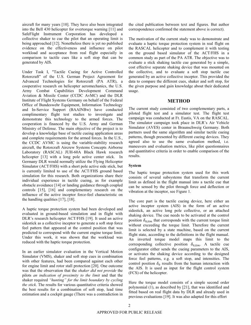
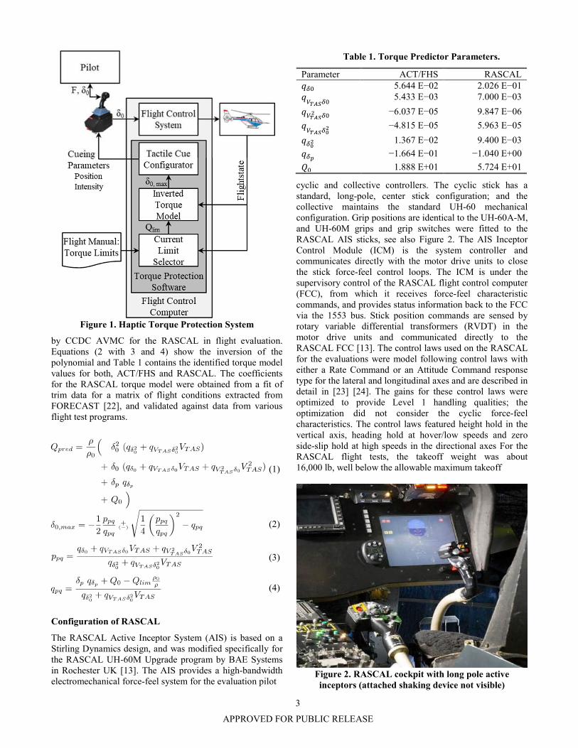
The haptic torque protection system used for this work consists of several subsystems that transform the current limit as defined in the flight manual into a tactile cue that can be sensed by the pilot through force and deflection or vibration at the inceptor, see Figure 1.
The core part is the tactile cueing device, here either an active inceptor system (AIS) in the form of an active sidestick, an active long pole collective, or an attached shaking device. The cue needs to be activated at the control position ��,��� that corresponds with the current torque limit without exceeding the torque limit. Therefore the current limit is selected by a state machine, based on the current flight state, according to the definitions in the flight manual. An inverted torque model maps this limit to the corresponding collective position ��,���. A tactile cue configurator either sends the cueing parameters to the AIS, or activates the shaking device according to the designed force feel patterns, e.g. a soft stop, and intensities. The control position �� results from the human interaction with the AIS. It is used as input for the flight control system (FCS) of the helicopter.
Here the torque model consists of a simple second order polynomial (1), as described by [21], that was identified and fitted based on real flight data by DLR and already used in previous evaluations [19]. It was also adapted for this effort
3
APPROVED FOR PUBLIC RELEASE
Figure 1. Haptic Torque Protection System
by CCDC AVMC for the RASCAL in flight evaluation. Equations (2 with 3 and 4) show the inversion of the polynomial and Table 1 contains the identified torque model values for both, ACT/FHS and RASCAL. The coefficients for the RASCAL torque model were obtained from a fit of trim data for a matrix of flight conditions extracted from FORECAST [22], and validated against data from various flight test programs.
(1)
(2)
(3)
(4)
Configuration of RASCAL
The RASCAL Active Inceptor System (AIS) is based on a Stirling Dynamics design, and was modified specifically for the RASCAL UH-60M Upgrade program by BAE Systems in Rochester UK [13]. The AIS provides a high-bandwidth electromechanical force-feel system for the evaluation pilot
Table 1. Torque Predictor Parameters.
Parameter ACT/FHS RASCAL ��� 5.644 E−02 2.026 E−01 �������
5.433 E−03 7.000 E−03
������ �� −6.037 E−05 9.847 E−06
�������
� −4.815 E−05 5.963 E−05
���� 1.367 E−02 9.400 E−03
��� −1.664 E−01 −1.040 E+00
�� 1.888 E+01 5.724 E+01
cyclic and collective controllers. The cyclic stick has a standard, long-pole, center stick configuration; and the collective maintains the standard UH-60 mechanical configuration. Grip positions are identical to the UH-60A-M, and UH-60M grips and grip switches were fitted to the RASCAL AIS sticks, see also Figure 2. The AIS Inceptor Control Module (ICM) is the system controller and communicates directly with the motor drive units to close the stick force-feel control loops. The ICM is under the supervisory control of the RASCAL flight control computer (FCC), from which it receives force-feel characteristic commands, and provides status information back to the FCC via the 1553 bus. Stick position commands are sensed by rotary variable differential transformers (RVDT) in the motor drive units and communicated directly to the RASCAL FCC [13]. The control laws used on the RASCAL for the evaluations were model following control laws with either a Rate Command or an Attitude Command response type for the lateral and longitudinal axes and are described in detail in [23] [24]. The gains for these control laws were optimized to provide Level 1 handling qualities; the optimization did not consider the cyclic force-feel characteristics. The control laws featured height hold in the vertical axis, heading hold at hover/low speeds and zero side-slip hold at high speeds in the directional axes For the RASCAL flight tests, the takeoff weight was about 16,000 lb, well below the allowable maximum takeoff
Figure 2. RASCAL cockpit with long pole active inceptors (attached shaking device not visible)

4
APPROVED FOR PUBLIC RELEASE
weight of the UH-60A. Also, there is a reduction in the dual engine maximum continuous torque that occurs at 80 kt. To simulate a maximum gross weight departure at 16,000 lb, here an artificial maximum takeoff power limit of 75 % torque was imposed below 80 kt, which reduced to maximum continuous power of 70% torque above 80 kt for the first of two mission profiles (MP1), which will be defined further below. For MP2, the respective limits were 70 % torque and 65 % torque. For evaluations with no collective tactile cueing, the pilot managed the torque using the torque gauge on the instrument panel, Figure 3, and for evaluations with tactile cueing the limit profile was programmed to change as described above at 80 kt. For the shaker collective tactile cueing, two levels of shaking were utilized, a warning level and a limit level. The limit level corresponded with the calculated ��,��� and the warning level started about 0.5 in (5%) below it. The SafeFlight® shaker is controlled by a voltage command of 0-10 volts DC that drives a DC motor and offset weight. Based on testing in the RASCAL simulator and in flight, the warning level used a 2 volts DC command, and the limit used 4 volts DC command. Because of the design of the shaker, switching shaker states (e.g. on, warning, limit, off), was not instantaneous, but required about one second to transition from one state to another.
Figure 3. RASCAL primary flight display with torque gauge (second scale from left)
Configuration of ground based simulator of ACT/FHS
The German part of the evaluation was performed in DLR’s ground based simulator of the ACT/FHS in the AVES simulator center. It replicates its cockpit that is located in a spherical vision dome providing a field of view of ± 120 deg horizontally and -35/+40 deg vertically [25]. It is equipped as the real ACT/FHS, with identical displays and inceptors, including the side-by-side arrangement with two electro-mechanical active sidesticks for the experimental pilot station at the right seat (Figure 4). The active sidestick for the collective axis was manufactured by Liebherr Aerospace GmbH. It is a two-axis short pole stick that provides a CAN-
Figure 4. ACT/FHS ground based simulator cockpit in DLR AVES; side-by-side active inceptor configuration
and experimental torque gauge highlighted
interface to receive the force-feel characteristics commands and to send position and force signals as well as status information to the FCC. The “Goldstick” from Stirling Dynamics was used for the right hand, cyclic control, but here without any tactile cues. The yaw axis was controlled via pedals. An attitude-command/attitude-hold response type was active in cyclic and a rate command/heading hold with turn coordination response type in yaw. There was no control system active in the collective axis. The torque and limits are presented on the so called First Limit Indicator (FLI), see Figure 5. The FLI combines several engine parameters and normalizes them relative to their limits. According to the manual the takeoff power limit at 78 %-torque, corresponding with the red line at 10 on the FLI-scale, is permitted for speeds lower than 65 kts. For faster speeds it only maximum continuous power at 69 %-torque, i.e. the start of the yellow area at 9 FLI-units, is permitted. The limit selector of the haptic torque protection system automatically decreased the maximum limit value early enough before reaching the condition by using a speed-in-5 s-prediction. Here only a tactile cue for the maximum limit was applied and no additional haptic cue for the MCP below 65 kt as in an earlier evaluation. No margin was used as this
Figure 5. Torque displayed on First-Limit-Indicator (FLI) ACT/FHS AVES for this evaluation (here the
markers are dislocated representing 1 FLI unit margin that was actually 0 in the experiment)

5
APPROVED FOR PUBLIC RELEASE
Table 2. Power/torque limit values.
Parameter ACT/FHS RASCAL Takeoff Power Limit / %-torque
78 75 (MP1) 70 (MP2)
Continuous Power Limit / %-torque
69 70 (MP1) 65 (MP2)
Speed threshold / kt 65 80
evaluation was performed in the simulator and not on the real aircraft. All power or torque limit values are summarized in Table 2. Helicopter mass and environmental conditions were static in the simulation.
Tactile cueing configurations
Three different cueing patterns were defined for the common test metric: The first configuration was a reference or baseline configuration with no tactile cueing. The second configuration was the shaker that was activated when the collective reached the collective position that was predicted to correspond with the current torque limit (��,���). The third configuration was the soft stop at that position. All three configurations are represented graphically in Figure 6.
Figure 6. Common test force-feel-configurations:
I: no tactile cue; II: shaker, III: soft stop (solid: spring force; dashed: friction).
Table 3. Force-feel parameters.
Parameter ACT/FHS RASCAL Basic friction / N (lbf) 2 11 (2.5) Basic gradient / N/mm, lbf/in 0 (0) 0 (0) Damping / - 0.0 0.8 Soft stop height / N (lbf) 40 (9.0) 27 (6.0) Soft stop width / mm (in) % -a) 2.0 (0.075) Shaker frequency / Hz 20 20 Shaker amplitude ± / N (lbf) 0.5 (0.1) b) 4.4 (1.0) b)
a) ideally zero, not calibrated; b)
set value, not calibrated
The force-feel configurations on the RASCAL and in the ground-based simulator of ACT/FHS were similar but not exactly identical. The basic characteristics of the active collective sidestick in the ground-based simulator of the ACT/FHS were pure dry friction, whereas there was a combination of dry friction and viscous damping present on RASCAL. The soft stop for the active collective sidestick in the ground-based simulator configuration was realized by using the built-in hard stop feature that was deactivated when reaching the set force threshold. Different to the soft stop, the hard stop is not programmed as a force-deflection gradient, but as a position hold. This was used to realize a steep gradient without the tendency to oscillate and, in combination with the basic friction, without hysteresis. The ACT/FHS stickshaker was realized using the built in feature of the sidestick in ground-based simulation; the RASCAL used the attached shaking device provided by SafeFlight®. All set parameter values are noted in Table 3. To increase the accuracy of the haptic torque protection system the collective deflection signal was limited to ��,��� in the FCC of the ACT/FHS as long as the stick was on that value or within in a predefined tolerance above it. This solution had been proposed by [21].
Pilots
Five pilots participated in the U.S. evaluation, two of which German pilots, and four pilots participated in the German evaluation, two of which U.S. pilots. One of the U.S. pilots and one of the German pilots participated in both evaluations. This resulted in a total number of seven different pilots, but nine complete evaluations. The pilot experience, affiliations and participations are summed up in Table 4. Six pilots are certified as test pilots (identified by by the * symbols) from U.S. (CCDC AVMC) or German
Table 4. Pilots.
Alias hours Affiliation Evaluation
US GER A* 2000 WTD-61 x B* 1650 WTD-61 x x C* 2568 CCDC AVMC x D* 3750 CCDC AVMC x x E* 4200 CCDC AVMC x F* 3000 CCDC AVMC x G 1800 GER BW x

6
APPROVED FOR PUBLIC RELEASE
(WTD-61) armed forces test centers. Pilot G is a regular pilot from the German armed forces (GER BW).
Procedure
The general requirements for the selection or design of the evaluation maneuvers was to necessitate the use of maximum power the use of and transition between the different torque limits. These maneuvers had to be practicable in a system evaluation setup, i.e. without much training and without specific infrastructure and be easily repeatable. They also had to be realistic enough to provide the context needed for piloted evaluation and to generate useful data.
As in a previous torque protection evaluation [19] two different takeoff maneuvers were designed and used to evaluate the haptic torque protection and its different force patterns in flight and in simulation: A vertical takeoff profile, named “Whiteout Escape” or mission profile (MP) 1 and a horizontal takeoff, named “Fog Departure” or MP2. The old whiteout escape profile was complemented by an additional flight phase, as explained hereafter. Both maneuvers were used in both test campaigns, i.e. with different helicopter types, RASCAL (flight test) and ground-based simulation of the ACT/FHS. Therefore some of the maneuver specification parameter values were adapted for power rating, or power regimes of the corresponding helicopter types. Also different than in the previous evaluation, the visual scene was artificially degraded by fog in the simulator evaluation.
Mission profile MP1 - Whiteout Escape is depicted in Figure 7. It consists of two phases: a vertical climb maneuver with maximum performance, i.e. maximum available power, out of a simulated or hypothetical whiteout condition and, after reaching the cloud top an ensuing transition into forward flight.
During the first stage of the mission profile the pilot's task consists of gaining altitude from a stable hover and reaching either the cloud top or predefined maneuver height as fast as possible. Therefore the pilot has to use maximum available power, e.g. maximum takeoff power or maximum continuous power. In the simulator campaign, the whiteout was simulated by placing a cloud with a defined height in the simulation scenery. Consequently, the pilot had to climb under poor visual references until he/she reached the cloud top and regained full visibility. In addition, the cloud simulation was dynamic, resulting in a variation of the cloud top height of about ±50 ft between the runs. The RASCAL flight tests were conducted under good visual conditions where the pilot had to reach a predefined height above ground. After reaching the top of the cloud the pilot had to accelerate until reaching a predefined velocity that was selected to be higher than the respective velocity threshold that necessitated the change of the torque limit into the reduced continuous power regime. The respective maneuver
Figure 7. Mission profile MP1 - Whiteout Escape.
Table 5. MP1 -Whiteout Escape Parameters.
Parameter ACT/FHS RASCAL h0 / ft 50 50 v0, v1 / kts 0 0 h1 / ft 250 (±50) a 250 h2 / ft 500 or h1+250 500 v2 / kts 70 80
aThis is the desired value, that was meant to correspond with the cloud top. But the simulated cloud was aging, i.e. the top height was varying throughout the simulator evaluation.
specification parameter values for RASCAL and ground-based simulator of the ACT/FHS are defined in Table 5.
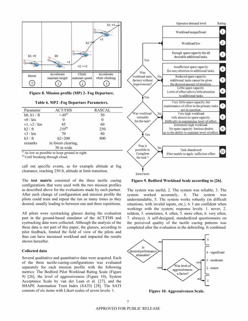
Mission profile MP2 - Fog Departure is a horizontal takeoff maneuver with maximum performance, see Figure 8 and Table 6 for the maneuver values. It is subdivided into three phases.
The task is to perform a takeoff in a simulated (ACT/FHS) or hypothetical (RASCAL) ground fog layer and break through as quick and safe as possible. From a stable low level hover the pilot first has to accelerate the helicopter until reaching the helicopters takeoff safety speed, here v1, using maximum takeoff power and staying as low as possible in order to keep visual contact to the ground (phase 1). In simulation the pilot had to control the height according to the visibility in simulated fog, whereas for the flight test the height was defined, see Table 6. In the second phase he or she has to break through the fog maintaining v1. After reaching the top of the cloud in the simulator or the predefined height in flight test the pilot had to accelerate again while maintaining the climb (phase 3) to a speed, that was selected to necessitate a reduction into the continuous power regime. The maneuver ends when reaching a predefined height above the ground (flight test) or above the cloud (simulation).
In both maneuvers the pilots are required to maintain constant heading, control the airspeed and use maximum permitted power. As a secondary task the pilots are asked to
7
APPROVED FOR PUBLIC RELEASE
Figure 8. Mission profile (MP) 2- Fog Departure.
Table 6. MP2 -Fog Departure Parameters.
Parameter ACT/FHS RASCAL h0, h1 / ft <40a) 50 v0 / kts 0 0 v1, v2 / kts 45 60 h2 / ft 250b) 250 v3 / kts 70 80 h3 / ft h2+200 800 remarks in forest clearing,
30 m wide
a) As low as possible to keep ground in sight. b) Until breaking through cloud.
call out specific events, as for example altitude at fog clearance, reaching 250 ft, altitude at limit transition.
The test matrix consisted of the three tactile cueing configurations that were used with the two mission profiles as described above for the evaluations made by each partner. After each change of configuration and mission profile the pilots could train and repeat the run as many times as they desired, usually leading to between one and three repetitions.
All pilots wore eyetracking glasses during the evaluation part in the ground-based simulator of the ACT/FHS and eyetracking data were collected. Although the analysis of the these data is not part of this paper, the glasses, according to pilot feedback, limited the field of view of the pilots and thus can have increased workload and impacted the results shown hereafter.
Collected data
Several qualitative and quantitative data were acquired. Each of the three tactile-cueing-configurations was evaluated separately for each mission profile with the following metrics: The Bedford Pilot Workload Rating Scale (Figure 9) [26], the level of aggressiveness (Figure 10), System Acceptance Scale by van der Laan et al. [27], and the SHAPE Automation Trust Index (SATI) [28]. The SATI consists of six items with Likert scales of seven levels: 1.
Figure 9. Bedford Workload Scale according to [26].
The system was useful, 2. The system was reliable, 3. The system worked accurately, 4. The system was understandable, 5. The system works robustly (in difficult situations, with invalid inputs, etc.), 6. I am confident when workings with the system; response levels: 1. never, 2. seldom, 3. sometimes, 4. often, 5. more often, 6. very often, 7. always). A self-designed, standardized questionnaire on the perceived quality of the tactile cueing patterns was completed after the evaluation in the debriefing. It combined
Figure 10. Aggressiveness Scale.

8
APPROVED FOR PUBLIC RELEASE
multiple-choice with open questions and took about 10 min to complete. Additionally flight data were recorded, including the flight states and inceptor signals, like control position and forces as well as the tactile cue activity.
RESULTS
The result graphs for the different questionnaires or metrics show the individual pilot ratings as well as the mean rating of the population for each of the features and the span of the calculated 95% confidence interval for the sample sizes of n=5 for RASCAL and n=4 for ACT/FHS.
Paired-sample t-tests were conducted in order to compare the results of each of tactile cueing configurations with the baseline or between the two tactile cueing configurations. The t-test is a statistics standard test described in common statistics literature, e.g. [29]. It states the probability p that the means of two populations are equal and the observed difference in means is only different by random error. In the contrary a p-value smaller than 0.05 means there is a 95% probability that the means are not equal, i.e. there is likely a significant effect of the rated feature on the used metric. – Nonetheless a p-value higher than 0.05 does not mean that there is no effect, just that random failure in the observations or ratings in the current samples cannot be excluded with the defined probability. Alternatively a p-value smaller than 0.05 is not sufficient to prove the validity of the observed effect, but necessary. A statistically significant difference, p < 0.05, is marked with * and a statistically marginal difference, 0.05 < p < 0.10, with **.
Quantitative Results
The time to reach the target height of 400 ft was only analyzed for the RASCAL flights, as in the ground-based simulation there was no distinct target height, but only the objective to get out of the simulated clouds until regaining vision. The height of the cloud top was also varying during the simulator experiment. The results showed no significant difference in the average time to reach 400 ft AGL for any of the mission profiles (Figure 11, Figure 12, Table 7 and Table 8).
Qualitative Results
The pilot ratings for the different standardized qualitative metrics and questions are presented graphically (Figure 13 - Figure 17). They are presented separately for the four different combinations of platforms and mission profiles. The means and standard deviations of the samples, as well as the p-values are summed up for the different metrics in Table 9 - Table 14.
All Bedford workload ratings were “tolerable” or better for all configurations, including the baseline in all sub-experiments, i.e. for both mission profiles and test environments (Figure 13). Each pilot rated lower or equal workload with the shaker cue than with the baseline configu-
Figure 11. Maneuver Time MP1 (RASCAL)
Figure 12. Maneuver Time MP2 (RASCAL)
Table 7. Maneuver time statistics
RASCAL (n=5)
Baseline Shaker Soft stop
Mean SD Mean SD Mean SD
MP1 20.60 2.37 19.79 1.37 18.60 1.15
MP2 26.18 2.89 25.05 0.89 24.94 1.64
Table 8. Maneuver time p-values
RASCAL (n=5)
Shaker vs. Baseline
Soft stop vs. Baseline
Soft stop vs Shaker
MP1 0.6271 0.1154 0.2242
MP2 0.2894 0.1636 0.8527
ration. And each pilot rated lower or equal workload for the soft stop than for the shaker configuration; with only the soft stop configuration showing all mean ratings being “satisfactory without reduction”. The mean workload ratings were slightly higher with MP2 than for MP1 and slightly higher for real flight evaluation with RASCAL than with ground-based simulator of the ACT/FHS. The values of the sample means and standard deviations are collected in Table 9. It yielded, that the difference of the shaker towards the
9
APPROVED FOR PUBLIC RELEASE
baseline was significant for MP1 and MP2 with RASCAL. The effect of the soft stop vs. baseline was significant for both environments in MP1, and in MP2 only marginal for RASCAL. The comparison between soft stop and shaker were significant for both environments in MP1 and in MP2 marginal for the ground-based simulator of the ACT/FHS. These results suggest that both, the soft stop as well as the shaker cue can reduce workload, but that the soft stop can reduce workload more than the shaker.
The aggressiveness ratings (Figure 14) showed similar relations as the Bedford workload ratings. In the average, the pilots had to limit their aggressiveness the most without tactile cueing, less with the shaker cue and least with the soft stop. The limitation was higher in MP2 than in MP1. In MP1 the ratings were slightly higher for RASCAL than for ground based simulator of the ACT/FHS. In MP2 the ratings were similar in both test environments. The exact mean values are collected in Table 11. The mean differences of the soft stop mean towards the baseline were significant for both MPs with RASCAL, see Table 12.
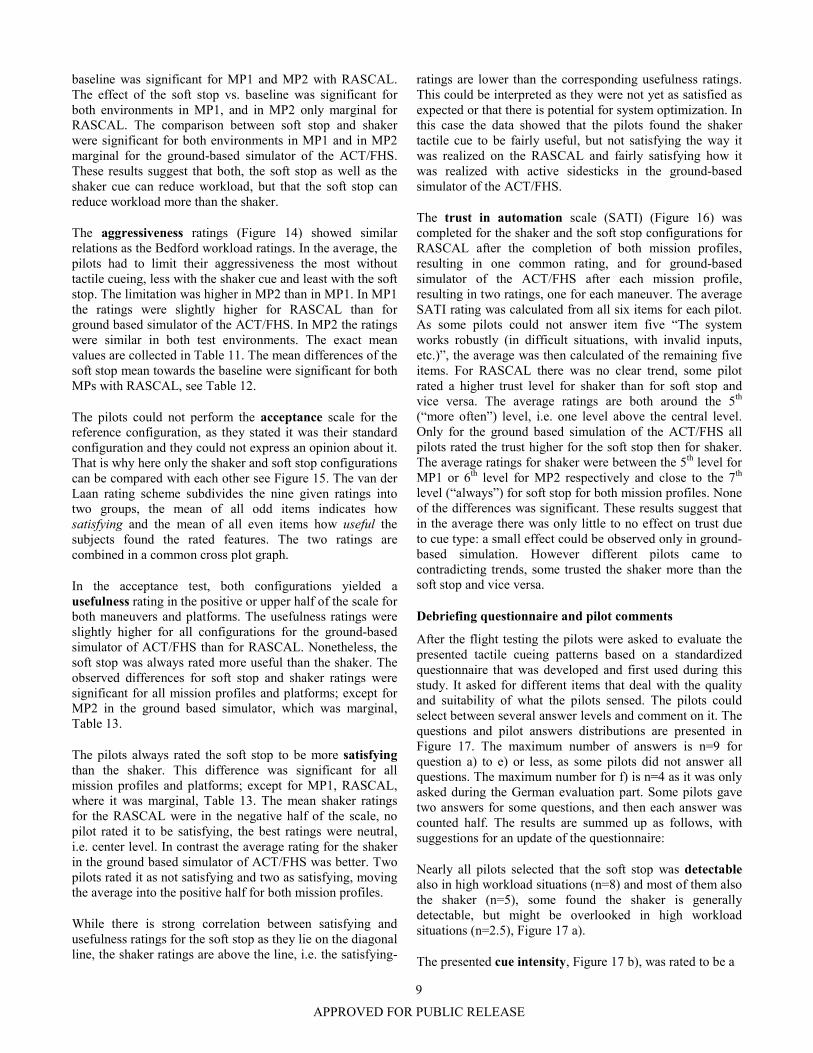
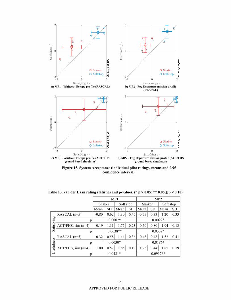
The pilots could not perform the acceptance scale for the reference configuration, as they stated it was their standard configuration and they could not express an opinion about it. That is why here only the shaker and soft stop configurations can be compared with each other see Figure 15. The van der Laan rating scheme subdivides the nine given ratings into two groups, the mean of all odd items indicates how satisfying and the mean of all even items how useful the subjects found the rated features. The two ratings are combined in a common cross plot graph.
In the acceptance test, both configurations yielded a usefulness rating in the positive or upper half of the scale for both maneuvers and platforms. The usefulness ratings were slightly higher for all configurations for the ground-based simulator of ACT/FHS than for RASCAL. Nonetheless, the soft stop was always rated more useful than the shaker. The observed differences for soft stop and shaker ratings were significant for all mission profiles and platforms; except for MP2 in the ground based simulator, which was marginal, Table 13.
The pilots always rated the soft stop to be more satisfying than the shaker. This difference was significant for all mission profiles and platforms; except for MP1, RASCAL, where it was marginal, Table 13. The mean shaker ratings for the RASCAL were in the negative half of the scale, no pilot rated it to be satisfying, the best ratings were neutral, i.e. center level. In contrast the average rating for the shaker in the ground based simulator of ACT/FHS was better. Two pilots rated it as not satisfying and two as satisfying, moving the average into the positive half for both mission profiles.
While there is strong correlation between satisfying and usefulness ratings for the soft stop as they lie on the diagonal line, the shaker ratings are above the line, i.e. the satisfying-
ratings are lower than the corresponding usefulness ratings. This could be interpreted as they were not yet as satisfied as expected or that there is potential for system optimization. In this case the data showed that the pilots found the shaker tactile cue to be fairly useful, but not satisfying the way it was realized on the RASCAL and fairly satisfying how it was realized with active sidesticks in the ground-based simulator of the ACT/FHS.
The trust in automation scale (SATI) (Figure 16) was completed for the shaker and the soft stop configurations for RASCAL after the completion of both mission profiles, resulting in one common rating, and for ground-based simulator of the ACT/FHS after each mission profile, resulting in two ratings, one for each maneuver. The average SATI rating was calculated from all six items for each pilot. As some pilots could not answer item five “The system works robustly (in difficult situations, with invalid inputs, etc.)”, the average was then calculated of the remaining five items. For RASCAL there was no clear trend, some pilot rated a higher trust level for shaker than for soft stop and vice versa. The average ratings are both around the 5th (“more often”) level, i.e. one level above the central level. Only for the ground based simulation of the ACT/FHS all pilots rated the trust higher for the soft stop then for shaker. The average ratings for shaker were between the 5th level for MP1 or 6th level for MP2 respectively and close to the 7th level (“always”) for soft stop for both mission profiles. None of the differences was significant. These results suggest that in the average there was only little to no effect on trust due to cue type: a small effect could be observed only in ground-based simulation. However different pilots came to contradicting trends, some trusted the shaker more than the soft stop and vice versa.
Debriefing questionnaire and pilot comments
After the flight testing the pilots were asked to evaluate the presented tactile cueing patterns based on a standardized questionnaire that was developed and first used during this study. It asked for different items that deal with the quality and suitability of what the pilots sensed. The pilots could select between several answer levels and comment on it. The questions and pilot answers distributions are presented in Figure 17. The maximum number of answers is n=9 for question a) to e) or less, as some pilots did not answer all questions. The maximum number for f) is n=4 as it was only asked during the German evaluation part. Some pilots gave two answers for some questions, and then each answer was counted half. The results are summed up as follows, with suggestions for an update of the questionnaire:
Nearly all pilots selected that the soft stop was detectable also in high workload situations (n=8) and most of them also the shaker (n=5), some found the shaker is generally detectable, but might be overlooked in high workload situations (n=2.5), Figure 17 a).
The presented cue intensity, Figure 17 b), was rated to be a

10
APPROVED FOR PUBLIC RELEASE
a) MP1 - Whiteout Escape profile (RASCAL) b) MP2- Fog Departure mission profile (RASCAL)
c) MP1- Whiteout Escape profile (ACT/FHS ground based simulator)
d) MP2- Fog Departure mission profile (ACT/FHS ground based simulator)
Figure 13. Bedford workload ratings (means and 0,95 confidence intervals, <= 9: Possible to complete the task; <= 6: Workload tolerable; <= 3: Workload satisfactory without reduction).
Table 9. Bedford workload rating statistics.
MP1 MP2
Baseline Shaker Soft stop Baseline Shaker Soft stop
Mean SD Mean SD Mean SD Mean SD Mean SD Mean SD
RASCAL (n=5) 4.60 0.90 3.60 0.55 2.40 0.55 4.80 1.30 3.80 0.84 3.00 0.71
ACT/FHS, sim (n=4) 3.25 0.50 2.75 0.50 1.50 0.58 4.75 0.96 4.00 0.00 3.00 0.82
Table 10. Bedford workload rating p-values (* p > 0.05; ** 0.05 ≤ p < 0.10).
MP1 MP2 Shaker vs. Baseline
Soft stop vs. Baseline
Soft stop vs. Shaker
Shaker vs. Baseline
Soft stop vs. Baseline
Soft stop vs. Shaker
RASCAL 0.0341* 0.0196* 0.0327* 0.0341* 0.0705** 0.2420
ACT/FHS (sim) 0.1817 0.0060* 0.0154* 0.2152 0.1018 0.0917**

11
APPROVED FOR PUBLIC RELEASE
a) MP1 - Whiteout Escape profile (RASCAL) b) MP2 - Fog Departure mission profile (RASCAL)
c) MP1 - Whiteout Escape profile (ACT/FHS ground based simulator)
d) MP2 - Fog Departure mission profile (ACT/FHS ground based simulator)
Figure 14. Aggressiveness (means and 0.95 confidence intervals).
Table 11. Aggressiveness rating statistics.
MP1 MP2
Baseline Shaker Soft stop Baseline Shaker Soft stop
Mean SD Mean SD Mean SD Mean SD Mean SD Mean SD
RASCAL (n=5) 2.60 0.90 2.00 1.22 1.20 0.45 3.40 1.14 2.80 1.10 1.60 0.90
ACT/FHS, sim (n=4) 2.25 1.50 1.50 1.00 1.25 0.50 3.00 0.82 2.50 0.58 2.00 0.82
Table 12. Aggressiveness rating p-values (* p > 0.05).
MP1 MP2 Shaker vs. Baseline
Soft stop vs. Baseline
Soft stop vs. Shaker
Shaker vs. Baseline
Soft stop vs. Baseline
Soft stop vs. Shaker
RASCAL 0.3046 0.0249* 0.2420 0.2080 0.0367* 0.1087
ACT/FHS (sim) 0.2152 0.1817 0.3910 0.1817 0.1817 0.1817
12
APPROVED FOR PUBLIC RELEASE
a) MP1 - Whiteout Escape profile (RASCAL) b) MP2 - Fog Departure mission profile
(RASCAL)
c) MP1 - Whiteout Escape profile (ACT/FHS
ground based simulator) d) MP2 - Fog Departure mission profile (ACT/FHS
ground based simulator)
Figure 15. System Acceptance (individual pilot ratings, means and 0.95 confidence interval).
Table 13. van der Laan rating statistics and p-values. (* p > 0.05; ** 0.05 ≤ p < 0.10).
MP1 MP2
Shaker Soft stop Shaker Soft stop
Mean SD Mean SD Mean SD Mean SD
Sat
isfy
ing
RASCAL (n=5) -0.80 0.62 1.30 0.45 -0.55 0.33 1.20 0.33
p 0.0002* 0.0022*
ACT/FHS, sim (n=4) 0.19 1.11 1.75 0.23 0.50 0.80 1.94 0.13
p 0.0638** 0.0339*
Use
fuln
ess RASCAL (n=5) 0.32 0.58 1.44 0.36 0.48 0.48 1.52 0.41
p 0.0030* 0.0186*
ACT/FHS, sim (n=4) 1.00 0.52 1.85 0.19 1.25 0.44 1.85 0.19
p 0.0481* 0.0917**

13
APPROVED FOR PUBLIC RELEASE
a) Common ratings based on both profiles (RASCAL)
b) MP1 - Whiteout Escape profile (ACT/FHS ground based simulator)
c) MP2 - Fog Departure mission profile (ACT/FHS ground based simulator)
Figure 16. Trust in Automation (SATI, means and 0.95 confidence intervals).
Table 14. SATI rating statistics.
MP1/MP2
Shaker Soft stop
Mean SD Mean SD
RASCAL (n=5) 3.79 1.37 3.84 1.08
p 0.9679
MP1 MP2
Shaker Soft stop Shaker Soft stop
Mean SD Mean SD Mean SD Mean SD
ACT/FHS, sim (n=4) 3.98 1.50 5.71 0.48 4.75 1.66 5.83 0.24
p 0.2304 0.1196

14
APPROVED FOR PUBLIC RELEASE
good compromise that prevents accidental, but allows intentional exceedance for both cue types (soft stop n=5.5, shaker n=3). Some pilots did not rate the intensity of the shaker, but remarked that the shaker does not prevent from exceedance or tell how much the limit is exceeded, i.e. if exactly on the limit or above. This is as expected, as in contrast to the soft stop the shaker does not have any additional force threshold that would need extra effort to exceed it. It shall be remarked here, that the exceedance of the limit cues was not part of the evaluation and the pilots tried to exceed it only out of curiosity. The exceedance threshold should be optimized in another experiment with an appropriate flight task. In the ground simulation of ACT/FHS the soft stop threshold was set to a value that was expected to be too high by intention, in order to measure the forces the pilot applied to get contact with and to stay on the cue which can be used as reference values for such an experiment. That explains why two pilots rated it as “too intense”. The formulation of the question and answer level should be split: It should be asked if the intensity was effective in avoiding unintended exceedances, and if the intensity allow the pilot to intentionally exceed the cue and operate beyond it if necessary? Especially a cue like the shaker might generate a strong sensation, but does not necessarily avoid unintended exceedance.
Almost all pilots rated, that oscillation at cue contact was “not factor” or “a factor, but tolerable” for both, soft stop and shaker, Figure 17 c). This implies the soft stop stiffness was not too high and did not produce intolerable oscillations.
The level of support dealt with identifying the right purpose for the different cues, Figure 17 d). As expected, shaker gained most ratings for “it warned me” (n=5.5) and soft stop for “it prevented and guided” (n=4.5). Currently the answer levels are combinations of more than two sub-items, like “warn and prevent”, “prevent and guide”. These combined purposes should be separated into single Likert-style items. The item “It allows carefree handling” should be added in this context. The influence of expectation should be put into a separate item and should be addressed specifically by an appropriate mission profile, where a cue could be presented to the pilot as instructed or by surprise, i.e. during an (unexpected) emergency.
The level of annoyance, Figure 17 e), was intended to learn, if and how much the cue disturbed and if the benefits or usefulness of the cue overweight the disturbance. This helps to identify the right purpose for the cueing pattern, i.e. made it tolerable for the sake of a lesser risk of torque exceedances. The distribution of answers shows that all except one pilot rated the soft stop to be “never annoying” or “sometimes annoying and the usefulness always outweighed the annoyance” (n=8). In contrast to that, the shaker was only rated like that by one half of the pilots, but the other half rated it as “sometimes annoying and the usefulness did not overweigh the annoyance”. The shaker variants on RASCAL and in the ground-based simulator of the
ACT/FHS received comparable ratings. However, this question or the answer levels do lack a fine granularity on the non-tolerable end. It should be updated, and ask specifically when and how often it may be tolerable, like: “Can it be permanently active, for warnings or caution messages or shall be reserved for emergencies?”
The agility rating showed that the position of the tactile cue moved slowly enough, so that the pilots could actively/consciously follow it, Figure 17 f).
The following pilot comments were collected during the evaluation and the debriefing (representative selection). These reflect the pilot’s way of utilizing the different cues and allow sorting the appropriate purposes.
RASCAL, - active long pole and separate shaking device:
Shaker: • Better than no cue, coarse cue cannot be precise • Good for alert, then you had to look at something, not
good for steady state cue • Difficult to distinguish change in vibration level
(warning vs. limit) • Difficult to “ride the limit”, cannot find the edge (can
result in PIO tendency) • Could be hard to distinguish from aircraft vibrations in
high workload environment Soft stop: • Greatly reduced workload monitoring torque, more
attention focused outside • Easy to follow the tactile cue, even when torque limit
changed • Improved performance, could get to desired faster
Ground based simulator of ACT/FHS - active sidestick:
General • Torque was very stable in sim. No exceedance
regardless of rate of application Shaker: • Not comfortable. But the lesser intensity than in
RASCAL was better. • Only notifies, does not prevent exceedance. • Not able to determine if on cue or beyond w/o constant
[visual] check. • Sometimes difficult to stay on the “stop“. • Had to reestablish contact, pumping up and down. • Good initial cue, but not useful for continued
operations. • Not to indicate reduction of limit. Had to manually
lower the stick at exceeding 65 kts. • Perhaps a [second] different shaker could communicate
“close to limit, but not over” and “over the limit“. Soft stop: • Carefree collective handling. • Obvious and intuitive. • Maximizes performance. • No need to verify torque visually.

15
APPROVED FOR PUBLIC RELEASE
not detectable/ not detected during tasks
generally detectable, but
might be overlooked in high workload
situations
detectable also in high wokload
situations
other*
not intense enough, could be accidentally
exceeded
good compromise:
prevents accidental and
allows intentional exceedance
too intense: does not allow
intentional exceedance
other*
a) Cue Detectabiliy: The presented tactile cue was…
b) Cue Force Intensity: The presented tactile cue was… *other: “Doesn’t prevent exceedance, it only notifies you that you are exceeding the limit.”; “No indicator of exceedance vs. right on cue”
not a factor a factor, but
tolerable not tolerable
warned me warned me and
prevented exceedance
when expected*
warned me and
prevented exceedance when not expected*
prevented and guided
other
c) Oscillation at Cue Contact: Oscillation was… d) Level of support: The presented tactile cue … *shortened:” warned me from unintendedly exceeding the limit when I
expected it / also when I not expected it.”
never annoying sometimes
annoying, but the usefulness
always overweight
sometimes annoying and the
usefulness did not overweigh the annoyance
always, annoying and the
usefulness did not overweigh
slow enough, so that I could
actively/consciously follow it
so fast, I could only passively
follow it
too fast to willingly
interact or maintain contact
e) Annoyance: The presented tactile cue was… f) Agility Level of moving cue: The position of the tactile cue moved…
Figure 17. Tactile Cueing Quality.
0
1
2
3
4
5
6
7
8n
Softstop FHS
Softstop RASCAL
Shaker FHS
Shaker RASCAL
0
1
2
3
4
5
6
7
8
n
Softstop FHS
Softstop RASCAL
Shaker FHS
Shaker RASCAL
0
1
2
3
4
5
6
7
8
n
Softstop FHS
Softstop RASCAL
Shaker FHS
Shaker RASCAL
0
1
2
3
4
5
6
7
8
n
Softstop FHS
Softstop RASCAL
Shaker FHS
Shaker RASCAL
0
1
2
3
4
5
6
7
8
n
Softstop FHS
Softstop RASCAL
Shaker FHS
Shaker RASCAL
0
1
2
3
4
5
6
7
8
n
Softstop FHS
Softstop RASCAL
Shaker FHS
Shaker RASCAL
16
APPROVED FOR PUBLIC RELEASE
DISCUSSION
The findings noted that a tactile cueing system for torque protection with either a stickshaker tactile cue or a soft stop generated by an active inceptor helps to reduce pilot workload and to increase aggressiveness during high performance takeoff maneuvers. With the soft stop cue the workload reduction and the pilot acceptance were higher than with the stickshaker cue. However, it could be shown that a retrofit solution with an attachable shaking device might be an alternative, when the integration of an active inceptor is not possible. In general the effects of the cues with regard to workload reduction contradict the results of prior research that compared soft stop and shaker cues in a simulator experiment. In the following specific aspects of the cues and their dedicated use are discussed.
The shaker was rated a useful cue in combination with the given task, nonetheless most of the pilots rated it to be not satisfying. In order to find the reason for this and possible solutions to increase the satisfaction it should be differentiated between general remarks on the shaker cue per se and the specific realizations that were used in the evaluation. Generally the shaking cue is good to alert and indicate when the stick approaches or exceeds the limit, but the current realizations gave a coarse cue that did not allow distinguishing between being on the limit and above the limit making it difficult to track the limit. The pilots had to confirm by looking at the visual gauges or pump the stick up and down to feel where the vibration starts or stops or changes the intensity. The latter strategy might provoke pilot aircraft coupling (PAC). Also a shaker cue might be overlooked in a vibratory environment under high workload.
Specifically, the stickshaker used in flight testing with RASCAL was rated less satisfying than the one used in ground-based simulation. It is not yet clear why it was rated less satisfying. It is probably a combination of several factors: One was that the device needed some time to spool up and made it difficult for the pilots to distinguish between the levels. Also the fact that it was used in a real aircraft with inherent vibration might have made detecting the cue more challenging than in the simulator. Another explanation for the higher satisfaction rating in the simulator was possibly the lower intensity of the shaker in the simulator: one of the pilots who had participated in the RASCAL experiment earlier had commented during the ground-based simulator evaluation that he found it less intensive than on RASCAL and thus more comfortable. The intensity should be optimized in future experiments.
A possible solution for the observed ambiguity with the shaker when it was clear whether the torque was still on or already above the limit could be by using different frequency and intensity levels, similar as already applied here, but with a slight difference in the handling. The pilot needs to stay in the low vibration level to get maximum power, but avoid the high intensity level to avoid overtorque. The width of the tolerance band should be optimized: It should be as short as
possible for high precision and as wide as necessary in order to avoid PAC resulting from pumping motions which may be provoked by the vagueness of the cue due to the spool-up time constants of the shaking device.
The soft stop was the preferred cue in combination with a haptic torque protection. It avoided unintended exceedance of the limit and helped the pilot to track the limit by “riding the cue”. This combination was also described as “carefree handling” approach in previous publications [30]. However it was not evaluated yet for situations where an intended exceedance is necessary. It is yet unknown how well the pilot can handle such situations. It is assumed that during exceedance, when the pilot has to permanently apply enough force to stay beyond the beginning of the soft stop, the workload might increase and the handling qualities decrease when the soft stop threshold gets too high. On the other hand the detectability and effectiveness against unintended exceedance will decrease when it gets too low. This makes tuning the threshold an optimization task that should be solved in other experiments.
A further aspect that might have an influence on cue preference or acceptance level is the accuracy of the prediction algorithm. The less accurate it is, the less the pilot could rely on it and the more he or she needed to control the torque her or himself respectively. A soft stop is expected to provide carefree capabilities and thus needs a high accuracy of the prediction algorithm, whereas with a shaker the pilots might possibly tolerate a less accurate predictor when it is used only to warn when close to the limit and leave the fine control to the pilot, based on the visual gauges. Nonetheless the softstop is expected to still have the higher workload reduction potential then the shaker. The predictor accuracy, however, was not in the focus of this paper and should be considered in future research. It should also be emphasized that the results are valid for similar transfer functions between the control input, here collective, and the limited state, here torque. Here the relation could be classified as quasi-steady [30], meaning the limited state is a steady or proportional and not a dynamic function of the input, or additional dynamics are relatively slow and do not tend to overshoot. It is expected there is a maximum allowed dynamics or speed for the use of the soft stop cue to provide carefree handling that needs to be identified.
The maneuver time was selected as a performance indicator, but did not show significant differences between the cues and the baseline. But this does not necessarily mean the tactile cueing had no effect on performance as this value is also influenced by other parameters like for example airspeed or sideslip angle or how accurate the pilot was following the defined mission profile. The literature has shown that it had a positive effect on various performance measures during simulator testing, for example how well the limit was avoided and how much of the available power could be used during the maneuvers, also referred to as “dwell time”. These analyses should be applied to the flight
17
APPROVED FOR PUBLIC RELEASE
data which were recorded during this evaluation to complement the results shown here, which focused mostly on subjective criteria.
Only parts of the analysis were statistically significant, which is most likely due to the relatively small sample size, i.e. number of pilots. However, the comments the pilots made during the evaluations and the discussions in the debriefings confirm and complement the results of the standardized questionnaires and together give a profound insight into the appropriate use of the compared cueing patterns.
CONCLUSIONS
1. A haptic torque protection system with either a stickshaker cue, generated by an active inceptor system or an attachable shaking device, or a soft stop cue can reduce the perceived pilot workload during high performance takeoff maneuvers. The soft stop cue reduced the workload more than the shaker. The workload difference between soft stop and shaker was comparable to the workload reduction between shaker and the baseline.
2. The system was evaluated in flight and in piloted simulation. Both environments showed similar results.
3. The soft stop is the preferred cue for this application, i.e. the avoidance of a quasisteady or proportional limit. It avoids unintended exceedance and allows to track the limit by “riding the cue”, enabling “carefree maneuvering”. It also enables the pilot to fly more aggressively.
4. A shaker is useful, but less useful than a soft stop. A shaker should be considered to cue the pilot to contact with the limit when the integration of an active inceptor system is not possible.
FUTURE WORK
The collected quantitative data will be analyzed in order to rate and compare the effects of the cueing patterns on performance.
Author contact: Mario Müllhäuser [email protected]
ACKNOWLEDGMENTS
This research was undertaken within the US-GERMAN Project Agreement – Advanced Technologies for Rotorcraft (PA ATR) that is funded by the US and GERMAN Ministries of Defense. The authors would like to thank the CCDC AVMC and the BAAINBw for their support, as well as the WTD61, in person Ernst Schmidt for his support and advice and of course the participating evaluation pilots and the RASCAL and AVES teams for their help. The authors would also like to acknowledge the supporting DLR undergraduate students Joe Wickham and Sonya Zhang who helped to process the questionnaires.
REFERENCES
1. Kim, S. K., Bothwell, M., and Fortenbaugh, R., “The Bell 525 Relentless, The World’s First ‘Next Generation’ Fly-by-Wire Commercial Helicopter,” Montréal and Québec (Canada), 2014.
2. Hoelscher, S. and Bothwell, M., “525 Aircraft Zero, The Relentless Advanced Systems Integration Lab,” Virginia Beach (VA), May 2015.
3. Enns, R., Dryfoos, J., Lukes, G., Hayes, P., and Kashawlic, B., “Adaptive Vehicle Management Systems Phase I Overview,” presented at the American Helicopter Society 69th Annual Forum, Phoenix (AZ), 2013.
4. Enns, R., Segner, D., and Dryfoos, J., “Adaptive Vehicle Management Systems Program Phase II Overview,” presented at the American Helicopter Society 72th Annual Forum, West Palm Beach (FL), May 2016.
5. Kashawlic, B., Enns, R., Brown, B., and Moore, R., “Maneuver and Mission Aiding via Tactile Cueing Flight Demonstrations,” presented at the American Helicopter Society 72th Annual Forum, West Palm Beach (FL), 2016.
6. Kashawlic, B., Enns, R., Irwin, J. G. I., and Moore, R., “Carefree Maneuvering via Tactile Cueing Flight Demonstrations,” presented at the American Helicopter Society 72th Annual Forum, West Palm Beach (FL), 2016.
7. Klein, G., Kashawlic, B., and Enns, R., “Design and Flight Test of an Adaptive Vehicle Management System on an AH-64 Helicopter Demonstrator,” presented at the American Helicopter Society 72th Annual Forum, West Palm Beach (FL), 2016.
8. SAE International, “Aerospace Active Inceptor Systems for Aircraft Flight and Engine Controls,” ARP5764, Feb. 2013.
9. Greenfield, A. et al., “CH-53K Control Law Risk Reduction Flight Testing on the Rascal UH-60a In-Flight Simulator,” presented at the American Helicopter Society 68th Annual Forum, Fort Worth (TX), 2012.
10. United States. Congress. Senate. Committee on Commerce, Science and Aviation, T. S. on, DC-10 Certification and Inspection Process: Hearings, Before the Subcommittee on Aviation of the Committee on Commerce, Science, and Transportation, United States Senate, Ninety-sixth Congress, First Session ... July 11 and 12, 1979. U.S. Government Printing Office, 1979.
11. McClellan, J. M., “Bell 430,” Flying Magazine, Mar. 2001.
12. Safeflight, “Products - Exceedance Warning Systems,” Tactile Cueing - Helicopter Safety By Feel.

18
APPROVED FOR PUBLIC RELEASE
https://www.safeflight.com/products/exceedance-warning-system/ (accessed Mar. 19, 2020).
13. Fletcher, J. W. et al., “UH-60M Upgrade Fly-By-Wire Flight Control Risk Reduction using the RASCAL JUH-60A In-Flight Simulator,” Montréal (Canada), May 2008.
14. Müllhäuser, M., “Tactile cueing with active cyclic stick for helicopter obstacle avoidance: development and pilot acceptance,” CEAS Aeronautical Journal, vol. 4, no. 2, pp. 27–37, 2017, doi: 10.1007/s13272-017-0271-2.
15. Lusardi, J., Fujizawa, B., and Morford, Z., “Flight Testing of Coupled Collective toward Reducing Pilot Workload during Landing in DVE,” presented at the American Helicopter Society 73th Annual Forum, Fort Worth (TX), 2017.
16. Lusardi, J., Fujizawa, B., and Cleary, M., “Flight Testing of Coupled Flight Controls toward Reducing Pilot Workload during Landing in DVE,” Philadelphia (PA), May 2019.
17. Lusardi, J. A., Blanken, C. L., Ott, C. R., Malpica, C. A., and Grünhagen, W. von, “In Flight Evaluation of Active Inceptor Force-Feel Characteristics and Handling Qualities,” Fort Worth (TX), May 2012.
18. Grünhagen, W. von, Müllhäuser, M., Höfinger, M., and Lusardi, J., “In-Flight Evaluation of Active Sidestick Parameters With Respect to Handling Qualities For Rate Command and Attitude Command Response Types,” presented at the American Helicopter Society Handling Quality Specialists Meeting 2014, Huntsville (AL), 2014.
19. Müllhäuser, M. and Leißling, D., “Development and In-Flight Evaluation of a Haptic Torque Protection,” Journal of the American Helicopter Society, vol. 64, no. 1, pp. 1–9, Jan. 2019, doi: 10.4050/JAHS.64.012003.
20. Whalley, M. S., Hindson, W. S., and Thiers, G. G., “A Comparison of Active Sidestick and Conventional Inceptors for Helicopter Flight Envelope Tactile Cueing,” Virginia Beach (VA), May 2000.
21. Sahani, N. A. and Horn, J. F., “Collective Axis Cueing and Limit Avoidance Algorithms for Carefree Maneuvering,” presented at the American Helicopter Society Flight Controls and Crew System Design Specialists’ Meeting, Philadelphia (PA), 2002.
22. Kim, F. D., “Formulation and Validation of High-Order Mathematical Models of Helicopter Flight Dynamics,” University of Maryland, 1991.
23. Mansur, M. H., Lusardi, J. A., Tischler, M. B., and Berger, T., “Achieving the Best Compromise Between Stability Margins and Disturbance Rejection Performance,” presented at the 65th Annual Forum of the American Helicopter Society, Grapewine (TX), May 2009.
24. Fujizawa, Brian T., “Response Type Tradeoffs in Helicopter Handling Qualities for the GVE,” presented at the 67th Forum of the American Helicopter Society, Virginia Beach (VA), May 2011.
25. Duda, H., Gerlach, T., Advani, S. K., and Potter, M., “Design of the DLR AVES Research Flight Simulator,” presented at the AIAA Modeling and Simulation Technologies (MST) Conference, Boston (MA), Aug. 2013, doi: 10.2514/6.2013-4737.
26. Roscoe, A. H. and Ellis, G. A., A subjective rating scale for assessing pilot workload in flight: A decade of practical use. Bedford (UK): Royal Aerospace Establishment, 1990.
27. van der Laan, J. D., Heino, A., and Waard, D. de, “A simple procedure for the assessment of acceptance of advanced transport telematics,” Transportation Research Part C: Emerging Technologies, vol. 5, no. 1, pp. 1–10, 1997, doi: 10.1016/S0968-090X(96)00025-3.
28. Dehn, D. M., “Assessing the Impact of Automation on the Air Traffic Controller: The SHAPE Questionnaires,” Air Traffic Control Quarterly, no. 16(2), pp. 127–146, 2008.
29. Dodge, Y., The Concise Encyclopedia of Statistics. New York (NY): Springer New York, 2008.
30. Jeram, G. J., “Open Platform for Limit Protection with Carefree Maneuver Applications,” PhD Thesis, Georgia Institute of Technology, Atlanta (GA), 2004.