Embed Size (px)
Citation preview
UCRL- JC-117018 PREPRINT
Utility of the U.S. National I nition Facility for Development of Inertial K: usion Energy
B. G. Logan, A. T. Anderson, M. T. Tobin- Lawrence Livermore National Laboratory
V. E. Schrock - University of California at Berkeley
W. R. Meier - W. J. Schafer Associates, Incorporated
R. 0. Bangerter - Lawrence Berkeley Laboratory
R. E. Tokheim - Poulter Laboratory, SRI International
M. A. Abdou - University of California at Los Angeles
K. R. Schultz - General Atomics
This paper was prepared for submittal to the 15th International Conference on Plasma Physics and
Controlled Nuclear Fusion Research Seville, Spain
September 26 - October 1,1994
August 1994
Thisisapreprintofapaper intended forpublicationina journalorptoceedings. Since changes may be made before publication, this preprint is made available with the understanding that it will not be cited or reproduced without the permission of the author.
Recycled Recyclable

DISCWMER
This document was prepared as an account of work sponsored by an agency of the United States Government. Neither the United States Government nor the University of California nor any of their employees, makes any warranty, express or implied, or assumes any legal liability or responsibility for the accuracy, completeness, or usefulness of any information, apparatus, product, or process disclosed, or represents that its use would not infringe privately owned rights. R e f m c e herein to any speaf~c commercial product, process, or service by trade name, trademark, manufacturer, or otherwise, does not necessarily constitute or imply its endorsement, recommendation, or favoring by the United States Government or the University of California. The views and opinions of authors expressed herein do not necessarily state or reflect those of the United States Government or the University of California, and shall not be used for advertising or product endorsement purposes.
.

DISCLAIMER
Portions of this document may be illegible in electronic image products. Images are produced from the best available original document.
UTILITY OF THE U.S. NATIONAL IGNITION FACILITY FOR DEVELOPMENT OF INERTIAL FUSION ENERGY
B. G. LOGAN, A. T. ANDERSON, M. T. TOBIN Lawrence Livermore National Laboratory
Livermore, California
V. E. SCHROCK University of California at Berkeley
Berkeley, California
W. R. MEIER W. J. Schafer Associates, Incorporated
Livermore, California
R. 0. BANGERER Lawrence Berkeley Laboratory
Berkeley, California
R. E. TOKHEIM Poulter Lab, SRI International
Menlo Park, California
M. A. ABDOU University of California at Los Angeles
Los Angeles, California
K. R. SCHULTZ General Atomics
San Diego, California
United States of America

ABSTRACT
IAEA-CN-60 f B-P-15
UTILITY OF THE U.S. NATIONAL IGNITION FACILITY FOR DEVELOPMENT OF INERTIAL FUSION ENERGY
This paper assesses the potential contributions of the U. S. National Ignition Facility (NIF) to the development of Inertial Fusion Energy (IFE). We find the NIF can provide important data in areas of target physics and fabrication technology useful to a variety of IFE driver and target options, in generic IFE target chamber phenomena and materials responses to target emissions, and in many IFE fusion power technology areas.
Page 2
1. INTRODUCTION
The demonstration of inertial fusion ignition and gain in the proposed U. S . National Ignition Facility (N@) [l], along with the parallel demonstration of the feasibility of an efficient, high-repetition-rate driver, would provide the basis for a follow-on Engineering Test Facility (Em) [2], a facility for integrated testing of the technologies needed for inertial fusion energy (IFE) power plants. The NIF target chamber is shown in Fig. 1. A workshop was convened at the University of California, Berkeley on February 22 - 24, 1994, attended by 61 participants from 17 U.S. organizations, to identify possible NIF experiments relevant to IFE. We considered experiments in four EE areas: target physics, target chamber dynamics, fusion power ethnology, and target systems, as defined in the following sections.
2. IFE TARGET PHYSICS EXPERIMENTS
The NIF ignition target physics program with indirect drive targets as the baseline plan will explore a range of target yields and gains, studying capsule implosion characteristics and symmetry requirements, and fusion ignition and burn physics. A total of 192 beamlets generating 1.8 MJ, 500 TW at 0.35 pm, can each amplify independent light input pulses, allowing significant flexibility to produce variable pulse shapes up to 20 ns and in different illumination geometries, including both direct and indirect drive capabilities. Table I lists IFE target physics issues for generic ion and laser drivers, and for direct and indirect drive illumination geometries. “X’s” marked in Table I indicate those issues that could be largely resolved using NIF capabilities. The table shows that the NIF can resolve most IFE target physics issues. NTF, along with Omega Upgrade, PBFA 11, and other ICF facilities around the world will be able to address all of the issues. The completion of these experiments will provide the target physics basis to proceed with an ETF.
(HIF) target based on the work of Ho and Tab& [3], 2(b) the laser-driven NIF target for ignition tests, and 2(c) a conceptual NIF-HIF model target to simulate capsule and x-ray transport physics reIevant to 2(a). Many fuel capsule requirements for 2(a) are less demanding than those for 2(b), as indicated. Recent success in volume-heating dense gas targets on the NOVA laser facility at LLNL supports future study of the use of gas radiators as in 2(c) to simulate the foam radiators of 2(a) [3].
Figure 2(a) shows an indirect drive target design for a heavy-ion fusion
3. TARGET CHAMBER DYNAMICS EXPERIMENTS
IFE target chamber dynamics issues addressable on NIF are: characterization of IFE target soft x-ray and debris emissions, response of first wall materials and protective-wall fluids to target emissions, and subsequent gas dynamics of the vapor blow-off, vapor condensation, and vacuum recovery. A typical NIF target output at a full target yield of 20 MJ will put - 50 Jkm2 of soft x-rays and target debris plasma on surfaces - I meter away from the target, similar to the deposition from - 350 MJ yields on walls - 4 m away in an IFE power plant target chamber. Thus, NIF can provide a reduced-scale test chamber environment representative of an JFE power plant. There are several l-D and 2-D hydrodynamics and radiation- hydrodynamics codes that need to calibration with NIF chamber-dynamics data, including CONRAD [4], HYADES [5] , SRIPUFFS [6], L2D [7], PHD-4 [7], and TSUNAMI [SI. NIF chamber dynamics experiments will need new diagnostics to measure ion velocities, energies, species, and flux originating from targets, and
Page 3

improvements of existing instruments to measure gas dynamics and condensation phenomena (e.g., fast response pressure transducers).
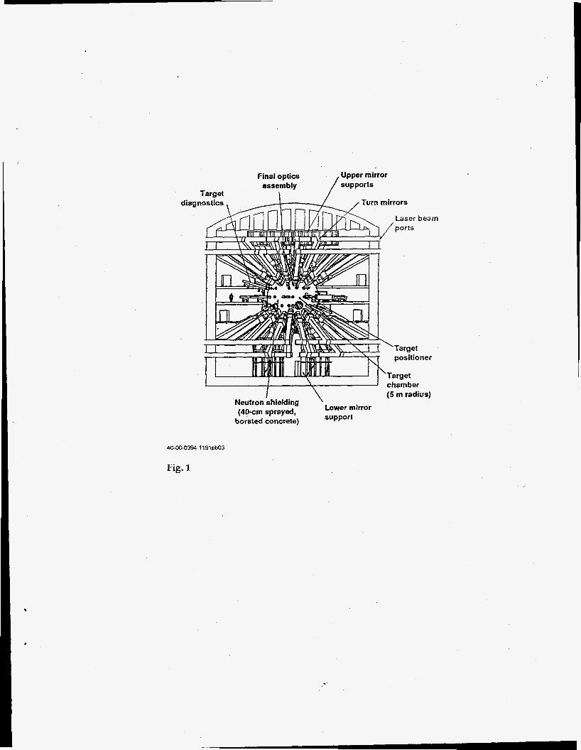
Figure 3 shows a possible NTF experiment designed to test the predictions of a chamber dynamics code such as TSUNAMI. The test assembly consists of a conical chamber in which a candidate material at the back surface is ablated by x-rays that are admitted through a hole in the larger front plate. The conical shape provides decreasing pressures along the row of transducers to test the 2-D modeling capability of codes. Condensation rates can be determined from pressure decay, and the amount and distribution of condensed material from pot+-shot analysis of the cone's inner and back surfaces.
4. FUSION POWER TECHNOLOGY EXPERIMENTS
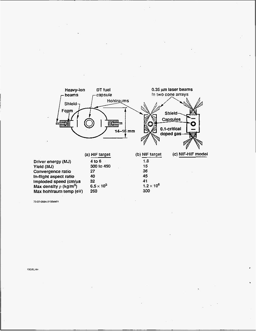
Basic operation as well as specific experiments on NIF can contribute data on IFE fusion power technology in the following areas: fusion ignition; design, construction, and operation of NIF (integrating many prototypical IFE subsystems); response of first-wall protection schemes; dose rate effects on radiation damage in materials; data on tritium burnup fractions in the target, some important tritium inventory and flow rate parameters, and data on achievable tritium breeding rate in samples; and neutronics data on radioactivity, nuclear heating and radiation shielding. With uniquely-high neutron dose rates of 10 to 1000 dpds, NIF can be useful for basic physics of radiation effects in materials, even for single shot exposure of samples. Examples include: cascades (morphology, size, fraction of free and clustered defects, impurities); microstructural evaluation; electrical properties; optical properties (fiber optics, coatings); and molecular cross linking. NIF can provide data testing Molecular Dynamic Simulation [MDS] codes [9], to improve predictions of microscopic bulk material responses to neutron damage. Figure 4 indicates how MDS calculations predicting overlap of damage clusters (a dose rate effect) can be validated with samples exposed to a single NIF shot.
5. IFE TARGET SYSTEMS TESTS
The NIF can provide important performance and sensitivity tests of candidate IFE target fabrication and transport parameters. In Table 2, we assessed both the potential NIF usefulness and uniqueness to resolve IFE target fabrication and transport issues. By stagger-firing four sections of the NIF laser chains - 200 ms apart, NIF may test a series of non-ignited model targets injected in a 5 Hz burst, to test the repeatability of beam-target engagement accuracy, in a multi-shot chamber environment. Most remaining IFE target systems developments can pursued separate from the NIF.
ACKNOWLEDGMENT
The authors would like to acknowledge the contributions of the sixty participants who attended the workshop at UC Berkeley February 22-24, 1994, who provided many of the ideas forming the basis of this paper. This work was performed under the auspices of the US Department of Energy by Lawrence Livermore National Laboratory under contract W-7405-Eng-48.
Page 4

.
.
REFERENCES [ 13 CAMPBELL, E. M., in Proc. of 14th ZAEA Znt. Con$ on Plasma Physics and Controlled Fusion Research, Wunburg, Germany, paper IAEA-CN-56fl3-3- 1 - 1, Vol. 111, p. 113 (1992) [2] The U.S. National Energy Policy Act of 1992 [3] HO, D.D.-M., and TABAK, M., in Proc. of I5th ZAEA Znt. Con$ on Plasma Physics and Controlled Fusion Research, this conference, paper IAEA- CN-60 /B-P-13. Tabak suggested the concept of using dense gas radiators for NIF- HIF model targets (LLNL, private cornlr,mication, 1994) [4] PETERSON, R. R., et. al., University of Wisconsin report UWFDM-670 (revised July 1988) [ 5 ] LARSEN, J., Cascade Applied Sciences Inc. code (licensed), version 01.05.04, July, 1992 [6] SEAMAN, L., and CURRAN, D., SRI Int., “SRIPUFF-Final Report, Vol. 11, March (1980) [7] COOPER, T., SVEDEFO Report No. DS 1980:16, December 1980 [8] LIU, J., C., et. al., Fusion Technology Vol. 21, pp. 1514-1519, 1992 [9] WONG, J., DIAZ DE LA RUBIA, T., GUINAN, M.W., TOBIN, M., PERLADO, J.M., PEREZ, A.S., and SANZ, J. LLNL report UCRL-JC-114789 Oct. 1, 1993, in Proc. of 6th Znt. Con$ on Fusion Reactor Materials, Stresa, Italy, 1993.
Page 5


TABLE I. IFE TARGET PHYSICS ISSUES FOR ION AND LASER DRIVERS, DIRECT AND INDIRECT DRIVE. AN ‘ X INDICATES ISSUES THAT CAN BE LARGELY RESOLVED WITH THE NIF CAPABILITIES.
Radiation flow, illumination geometry
Advanced targets X X X X I
Page 7
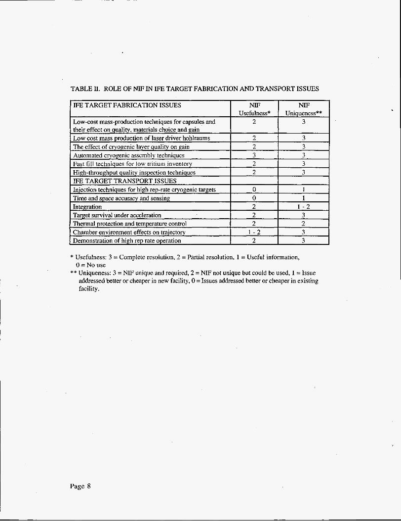
TABLE II. ROLE OF NE IN WE TARGET FABRICATION AND TRANSPORT ISSUES
High-throughput quality inspection techniques I 2 I 3 IFE TARGET TRANSPORT ISSUES
* Usefulness: 3 = Complete resolution, 2 = Partial resolution, 1 = Useful information,
** Uniqueness: 3 = NIF unique and required, 2 = NIF not unique but could be used, 1 = Issue 0 = No use
addressed better or cheaper in new facility, 0 =Issues addressed better or cheaper in existing facility.
Page 8
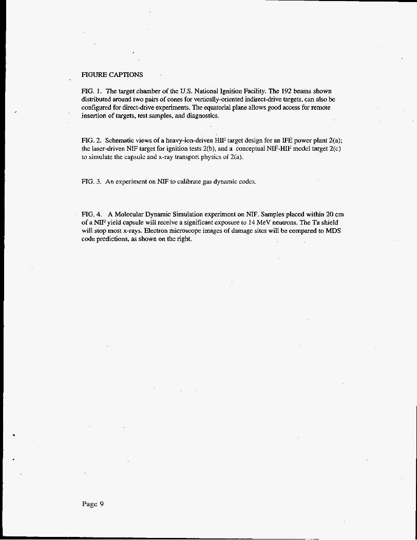
FIGURE CAPTIONS
FIG. 1. The target chamber of the U.S. National Ignition Facility. The 192 beams shown distributed around two pairs of cones for vertically-oriented indirect-drive targets, can also be configured for directdrive experiments. The equatorial plane allows good access for remote insertion of targets, test samples, and diagnostics.
mG. 2. Schematic views of a heavy-ion-driven HIF target design for an IFE power plant 2(a); the laser-driven NIF target for ignition tests 2(b), and a conceptual NIF-HIF model target 2(c) to simulate the capsule and x-ray transport physics of 2(a).
FIG. 3. An experiment on NIF to calibrate gas dynamic codes.
- FIG. 4. A Molecular Dynamic Simulation experiment on NE. Samples placed within 20 cm of a NIF yield capsule will receive a significant exposure to 14 MeV neutrons. The Ta shield will stop most x-rays. Electron microscope images of damage sites will be compared to MDS code predictions, as shown on the right.
Page 9
Taraet
I I \ I chamber I (5 rn radius)
Neutron shielding ' Lower mirror (40-crn sprayed,
borated concrete) support
Fig. 1
Heavy-ion DT fuel 0.35 pm laser beams
(a) HIF target Driver energy (MJ) 4 to 6 Yield (MJ) 300 to 450 Convergence ratio 27 In-flight aspect ratio 40 Imploded speed (cm/ps 32 Max density p (kg/rn3) Max hohlraum temp (eV) 260
6.5 x lo5
(b) NIF target (c) NIF-HIF model 1.8 15 36 45 41
300 1.2 x lo6
70-374494-31-1
c

Test material for ablation \ A
Pressure transducers
Transducer
X-rays from
....... target
......
Pressure transducers
SEMlAFM
Peak values, condensation effects, reflection strength
Post-shot material removal depth from near surface
I XRF I Trace surface analysis for condensed material distribution I IFE first wall
NIF expt OSlRlS HYLIFE CASCADE
X-ray fluence 200J/cm2 60J/cm2 2000J/cm2 60J/cm2 @ radius 0.4 m 3.5 m O S m 3.1 m
Ablation depth 20 F 20 Pn 200 pm 3-
Time scale 4 O p e c 700psec 5 0 p e c 9Opsec
Fig. 3

t 2-5 ~m
Capsule 1 0 A 1 5 nlshot
Shield 1 Sample array
L
-100 4 -100 -50 0 50 100
(A)