Embed Size (px)
Citation preview
Charles R. Pierce Regulatory Affairs Director
April 11, 2016
Docket Nos.: 50-348 50-364
Southern Nuclear Operating Company, Inc. 40 Inverness Center Parkway Post Office Box 1295 Birmingham, AL 35242
Tel 205.992.7872 Fax 205.992.7601
U.S. Nuclear Regulatory Commission ATIN: Document Control Desk Washington, D. C. 20555-0001
Joseph M. Farley Nuclear Plant- Units 1 and 2 Response to Request for Additional Information for
SOUTHERN«\ NUCLEAR
A SOUTHERN COMPANY
NL-16-0415
TS 3.3.5 Loss of Power Diesel Generator Start Instrumentation LAR
Ladies and Gentlemen:
By letter dated November 20, 2015 (NL-15-0722, Agencywide Documents Access and Management System (ADAMS) Accession No. ML 15324A297), as supplemented by letter dated January 12,2016 (NL-16-0007, ADAMS Accession No. ML 16012A457), Southern Nuclear Operating Company (SNC) submitted a license amendment request (LAR) to revise Technical Specification (TS) 3.3.5, "Loss of Power Diesel Generator Start Instrumentation," at Joseph M. Farley Nuclear Plant (FNP), Units 1 and 2 to enable compliance with license conditions for each unit which require elimination of reliance on manual actions as part of the degraded voltage protection scheme.
By letter dated March 11, 2016 (ADAMS Accession No. ML 16060A 161 ), the Nuclear Regulatory Commission (NRC) sent SNC a request for additional information (RAI). The enclosures to this letter provide the SNC responses to the NRC RAI items.
This Jetter contains no new NRC commitments. If you have any questions, please contact Ken McElroy at {205) 992-7369.

U.S. Nuclear Regulatory Commission NL-16-0415 Page 2
Mr. Pierce states he is Regulatory Affairs Director for Southern Nuclear Operating Company, is authorized to execute this oath on behalf of Southern Nuclear Operating Company and, to the best of his knowledge and belief, the facts set forth in this letter are true.
titJ:itted, \11 I f
,, l ) I ( r ~J ,, ... t. .. ) ' \ .
C. R. Pierce ',t / .. <, I { ... ' Regulatory Affairs Director
~ (
; t ' ) I ' ' '? .,.. l ..
CRP/DWDI<>
Sworn to and subscribrr:; me this J/ ~day ot--#-A:..:..~-'-rz--'t_L-____ , 2016.
~~pi' d-My commission expires: /0 ~ 'Z · Zo f 1
Enclosure 1: SNC Response to RAis Enclosure 2: Type CV-2 and Type 27N Undervoltage Relay Operating Curves Enclosure 3: In-Process Revision to FSAR 8.2.2.4
cc: Southern Nuclear Operating Company Mr. S. E. Kuczynski, Chairman, President & CEO Mr. D. G. Bost, Executive Vice President & Chief Nuclear Officer Ms. C. A. Gayheart, Vice President- Farley Mr. M.D. Meier, Vice President- Regulatory Affairs Mr. D. R. Madison, Vice President- Fleet Operations Mr. B. J. Adams, Vice President- Engineering Ms. B. L. Taylor, Regulatory Affairs Manager - Farley RTYPE: CFA04.054
U.S. Nuclear Regulatorv Commission Ms. C. Haney, Regional Administrator Mr. S. A. Williams, NRR Project Manager- Farley Mr. P. K. Niebaum, Senior Resident Inspector- Farley
Alabama Department of Public Health Dr. T. M. Miller, MD, State Health Officer
J I I ,• I

Joseph M. Farley Nuclear Plant Response to Request for Additional Information for
TS 3.3.5 Loss of Power Diesel Generator Start Instrumentation LAR
Enclosure 1
SNC Response to RAis

Enclosure 1 to NL-16-0415 SNC Response to RAis
By letter dated November 20, 2015 (NL-15-0722, Agencywide Documents Access and Management System (ADAMS) Accession No. ML 15324A297), as supplemented by letter dated January 12,2016 (NL-16-0007, ADAMS Accession No. ML 160 12A457), Southern Nuclear Operating Company (SNC) submitted a license amendment request (LAR) to revise Technical Specification (TS) 3.3.5, "Loss of Power Diesel Generator Start Instrumentation," at Joseph M. Farley Nuclear Plant (FNP), Units 1 and 2 to enable compliance with license conditions for each unit which require elimination of reliance on manual actions as part of the degraded voltage protection scheme.
By letter dated March 11, 2016 (ADAMS Accession No. ML 16060A 161 ), the Nuclear Regulatory Commission (NRC) sent SNC a request for additional information (RAI). This enclosure provides the SNC response to the NRC RAI items.
NRC RAI No. 1:
In Enclosure 1, page E1-3, of the License Amendment Request (LAR), it was stated "Because the new solid-state relays provide for discrete setting of actuation delay time rather than actuating according to an inverse-time characteristic curve like the existing induction disc relays, a Delay Time column is added to Table 3.3.5-2." It was also stated "Installation of the new DVRs is planned to be performed one bus at a time over two successive refueling outages for each unit, beginning with Bus 2G in spring 2016 (2R24) and Bus 1 G in fall 2016 (1 R27)."
Please explain the basis for not replacing the induction type relays with solid state relays for loss of voltage (LOV) relays. Provide vendor supplied operating curves for the new solid state 27N type relays as well as induction disc relays (currently in use).
SNC Response to RAI No. 1:
1. The proposed LAR is needed to bring FNP into compliance with license conditions requiring elimination of the manual actions which are relied upon as part of the existing protection scheme for the Degraded Grid Voltage (DGV) function of TS 3.3.5. Because of the small margins available between the minimum expected voltage (MEV) and minimum required voltage (MRV) for some equipment powered by the 4.16 kilovolt (kV) emergency buses, replacement of the existing Type CV-2 induction disc relays with more accurate, discretely adjustable Type 27N solid state relays is necessary to enable implementation of relay actuation setpoints which will achieve fully automatic operation for the DGV function. In contrast, rather than actuating within a narrow band of allowable values for voltage and delay time, the Loss of Voltage (LOV) function requires relays to actuate in response to a rapid and severe voltage drop. No manual actions are relied upon in the existing protection scheme for the LOV function and the Type CV-2 relays remain well suited for this application.
Vendor-supplied operating curves are provided for the Type CV-2 and Type 27N relays in Enclosure 2.
E1-1

Enclosure 1 to NL-16-0415 SNC Response to RAis
RAI No.2
Calculation SE-SNC529029-001, Table 6 (ML 16012A457) listed low degraded voltage margins for motors and motor operated valves (MOVs) as shown below.
Table 6. Low Degraded Voltage Margin Motors and MOVs per Attachment 1. Motor Name Case Study Voltage Req. MOV 8803A MS 1.5F 75.30% MOV 3024A MS 1.5F 72.87% MOV 30248 MS 1.5F 72.87% LCV 01158 MS 1.5F 74.96% MOVV516 MS 1.5G 75.09% MOV 88038 MS 1.5G 68.35% MOV 8100 MS 1.5G 68.35%
MOV 3232A MS 1.5G 73.19% MOV 32328 MS 1.5G 68.02% MOV 3232C MS 1.5G 68.02% LCV 01150 MS 1.5G 68.35% MOV 3318A MS 1.5G 70.00% MOV 27698 MS 1.5G 68.65% MOV 34788 MS 1.5G 70.41%
Ctrl Rm Press Supply Fan B MS 1.5G 74.00% Ctrl Rm HVAC Blower 1 B LF 1.4G 90.00%
Ctrl Rm Rad Monitor B LF 1.3G 90.00% "Licensee provided Assumption 3 for undervoltage justrficatlon (see LAR) **Recommended for TOL replacement
Voltage 75.78% 72.87% 72.87% 75.42% 75.59% 68.76% 68.63% 71 .32% 66.29% 66.29% 68.74% 69.93% 68.65% 70.41% 74.23% 90.12% 88.31%
"""licensee provided Attachment 1, Note 6 for undervoltage justification (see LAR)
Margin 0.48% 0.00% 0.00% 0.46% 0.50% 0.41% 0.28%
-1 .87%* -1.73%* -1.73%* 0.39%
-0.07%"* 0.00% 0.00% 0.23% 0.12%
1.69%***
In regards to the information on this table, please answer the following questions:
a) Based on the table above, the available voltage at the terminals of the MOVs 3232A, 32328, 3232C, 27698, and 34788 have negative or no margin. Please provide sufficient technical and regulatory bases to verify that these MOVs will perform their worst-case design basis safety functions such as opening or closing the valves within the times assumed in the design basis including the required minimum required open/close coil pickup voltage (control circuit voltage) without actuating the protective devices such as breakers, relays, fuses etc.
b) Case Studies MS 1.5F and MS 1.5G with group start (assuming safety injection signal present) and degraded voltage show that they are near the TS lower allowable value of 3760.75V (Enclosure 3, Supplement dated January 12, 2016). Please provide the available voltage at the motor control centers (listed in Table 6) and at MOV motor terminals. Also, please provide evaluations that confirm that these MOVs have adequate starting torque and close/open coil pickup voltage.
c) MOVs 3318A for Units 1 and 2 would achieve the required voltage by replacement of the thermal overload (TOL) heater with one of a lower resistance. Please clarify whether the modifications
E1-2

Enclosure 1 to NL-16-0415 SNC Response to RAis
associated with this replacement are completed or not. If not, provide justification why this condition is acceptable until the modifications are completed.
SNC Response to RAI No. 2:
2.a All motor operated valves (MOVs) required for safe shutdown have positive and adequate voltage margin to perform their safety function at the degraded voltage relay (DVR) lower analytical limit (LAL), which is the voltage at which the DVR is guaranteed to trip. The referenced margin in Table 6 of SE-SNC529029-001 is not margin with respect to TS requirements, but is the margin at the MOVs when the 4.16 kilovolt (kV) bus voltage is at the minimum required voltage (MRV). This MRV is lower than the LAL, ensuring that the DVR will trip at voltages above those required to support the safety-related loads.
Regarding MOVs QSV49MOV2769B and QSV49MOV3478B, which show zero voltage margin in Table 6 of SE-SNC529029-001, this state of zero margin defines the MRV at 4.16 kV Bus 1 G. The MRV is a lower voltage than the DVR LAL, which is the 4.16 kV bus voltage at which the DVR is guaranteed to trip. Therefore, the DVR is guaranteed to trip at voltages above the MRV and consequently at a voltage that yields approximately 0.75% positive margin at the 2769B and 3478B MOVs. See Table 2.1 below for an example of this positive margin.
Table 2.a- Example Voltage Analysis Comparing LAL to MRV for MOV QSV49MOV2769B and QSV49MOV3478B
Voltage at LAL Voltage at MRV Voltage at Bus 1 G (4.16 kV) 89.35% 88.60% Voltage at MOV 2769B and 3478B (550 V) 69.4%* 68.65% Margin at MOV 2769B and 3478B (550 V) 0.75%* 0.00%
*These voltages are estimated by adding the voltage increase at the 4.16 kV bus from the MRV to the LAL (0.75%) to the voltage at the MOV terminals.
If bus voltage falls below the DVR trip setpoint, the DVR will trip prior to any MOV protective devices. Thermal overloads (TOLs) will trip in approximately 25.6 and 16.0 seconds for 2769B and 3478B, respectively. This is longer than the DVR time delay allowable value of 11.4 seconds, meaning the DVR will trip before the MOV TOLs.
Control power fuses are adequately sized to not melt on extended contactor inrush current. Contactors have adequate voltage to pick up at the event initiation. The minimum required motor control center (MCC) voltage for contactor pickup is 82.89% at 600 V MCC 1 G, which feeds MOVs 2769B and 3478B. The prestart voltage at this MCC is 84.73% of 600 V, therefore, the contactor will pick up at the event initiation.
E1-3

Enclosure 1 to NL-16-0415 SNC Response to RAis
A different methodology is used to analyze the steam generator main feed stop check MOVs 01 N21 MOV3232A, 01 N21 MOV32328, and 01 N21 MOV3232C, which have adequate voltage to perform their safety function. These MOVs show negative voltage margin in Table 6 of SESNC529029-001 for the loss of coolant accident (LOCA) group motor start case with the 4.16 kV Bus 1 G prestart voltage at the MRV. However, the methodology used to determine that margin, which matches the methodology of the design basis load studies, is overly conservative.
The actual minimum available voltage margin at the 3232 MOVs during a LOCA Group Start is 5.6% of 550 V. The 3232 MOVs are modeled by SE-SNC529029-001 and SE-SNC529029-002 as drawing locked-rotor current (> 250 amps each) at the event initiation, when in reality, during a LOCA Group Motor Start the safety function if these MOVs is to go closed, and the MOVs draw only full-load current(< 65 amps each) until the valves seat themselves in approximately 30 seconds, at which point either the voltage has recovered to acceptable levels to reset the DVR or the DVR has already tripped. Note also that after a short duration (< 1 second), the voltage at the MCC will begin to increase rapidly as other loads on the MCC transition from locked-rotor to full load operation. The 3232 MOVs are modeled as drawing locked-rotor current at degraded voltage only after the plant has reached LOCA steady-state voltages.
If voltage falls below the DVR trip setpoint, the DVR will trip prior to any MOV protective devices. TOLs will trip in a minimum of 13.87 seconds for the 3232 MOVs. This is longer than the DVR time delay allowable value of 11.4 seconds, meaning the DVR will trip prior to the MOV protective devices.
Control power fuses are adequately sized to not melt on extended contactor inrush current. Contactors have adequate voltage to pick up at the event initiation. The minimum required motor control center (MCC) voltage for contactor pickup is 74.99% at 600 V MCC 1V, which feeds the 3232 MOVs. The prestart voltage at this MCC is 85.47% of 600 V, therefore the contactor will pick up at the event initiation.
2.b MOVs required for safe shutdown have adequate starting torque and close/open coil pickup voltage above the MRV. For motors listed in Table 6 of SE-SNC529029-001, Table 2.b below shows that the MCC pre-start voltage is greater than the contactor pickup voltage requirement; the MCC starting voltage is greater than the contactor dropout MCC voltage requirement; and the MOV motor terminal voltage is greater than the motor voltage requirement, which is the minimum voltage necessary to ensure adequate torque at the motors. The voltage requirements provided in this evaluation were considered in determining the available voltage margin at safety-related MOVs with the 4.16 kV bus voltage at the MRV.
E1-4

Enclosure 1 to NL-16-0415 SNC Response to RAis
Table 2.b- MCC, Motor Terminal, and Contactor Voltages for Unit 1 Low-Margin Motors
Coil Pickup MCC MCC MCC Coil Dropout
Pre-Start Voltage Starting MCC Voltage Voltage Required Voltage Required
MOV8803A 86.23% 75.42% 75.73% 39.86%
MOV3024A 86.23% 75.27% 75.73% 39.78%
MOV 30248 86.23% 75.24% 75.73% 39.77%
LCV 01158 86.23% 76.72% 75.73% 40.55%
MOV V516 85.37% 78.05% 69.98% 68.30%
MOV 88038 85.47% 75.50% 69.23% 39.91%
MOV 8100 85.47% 76.76% 69.23% 40.58%
MOV3232A 85.47% 74.99% 69.23% 48.58%
MOV3232B 85.47% 74.99% 69.23% 48.58%
MOV3232C 85.47% 74.99% 69.23% 48.58%
LCV 01150 85.47% 76.70% 69.23% 40.54%
MOV 3318A 85.47% 75.07% 69.23% 39.68%
MOV 27698 84.73% 75.86% 69.81% 40.10%
MOV3478B 84.73% 76.39% 69.81% 40.38%
Ctrl Rm Press 84.73% 75.42% 69.81% 39.86% Supply Fan B Ctrl Rm HVAC 87.92%** 87.14% 87.92%** 70.17%
Blower 18 *Acceptable per response to RAI 2.a **Control power fed from separate 208 V control power panel ***Voltage requirement to provide adequate starting torque
E1-5
MOV Motor Motor Voltage Terminal Required*** Voltage
75.78% 75.30%
72.87% 72.87%
72.87% 72.87%
75.42% 74.96%
75.59% 75.09%
68.76% 68.35%
68.63% 68.35%
71.32%* 71.82%*
66.29%* 71.82%*
66.29%* 71.82%*
68.74% 68.35%
69.93% 70.00%
68.65% 68.65%
70.41% 70.41%
74.23% 74.00%
85.96% 75.00%

Enclosure 1 to NL-16-0415 SNC Response to RAis
2.c MOVs 01 E14MOV3318A (Unit 1), Q2E14MOV3318A (Unit 2), and 01 P16MOV3024D (Unit 2) are scheduled to have their TOL heater elements replaced by Fall 2016, before the proposed LAR would become effective. These MOVs currently meet voltage requirements when switchyard voltage is at the current MEV of 100% of 230 kV. At degraded switchyard voltages below 100%, FNP uses operator actions to mitigate voltage conditions adverse to the operation of required safety systems, in accordance with the current licensing basis.
NRC RAI No. 3:
In calculation SE-SNC529029-001, Version 1.0 (Enclosure 1, Supplement dated January 12, 2016), Assumptions Section, it states "minimum expected grid voltage of 101.0% at the 230 kV Reference Bus is assumed and utilized in the ETAP model based on contingency studies defined by the FSAR (Farley Nuclear Plant, Units 1 and 2, FSAR, Rev. 26, Feb. 2015)." In, it states "System voltages for worst-case contingencies are expected to remain at or above 1 00% of 230 kV." It was also stated ''The value of 100% assures acceptable terminal voltages, with margin, for safe shutdown equipment to perform its safety function. Therefore, continued unit operation is acceptable in the unlikely event that system voltage is found to be < 101.6% but above 1 00%."
Please provide the technical basis for not using the 1 00% of 230 kV of the system voltage in determining the degraded voltage relay (DVR) setpoints and limiting components.
SNC Response to RAI No. 3:
3. The FNP Final Safety Analysis Report (FSAR), at Section 8.2.2.4, "Offsite Power System Operating Voltage Range," states that offsite power system voltage is not intentionally lowered below 101.6% (of 230 kV). This is consistent with the Nuclear Plant Interface Requirements (NIPR) agreement for FNP, in compliance with North American Electric Reliability Corporation (NERC) standard NUC-001 , "Nuclear Plant Interface Coordination." FSAR 8.2.2.4 also states that system voltages are expected to remain at or above 100% for worst-case single contingencies and that 100% assures acceptable voltages for safe shutdown equipment to perform its safety function.
However, in order to gain sufficient margin (with allowance for inaccuracies arising from calibration tolerances, setpoint drift, etc.) to enable the new, higher DVR actuation voltage Allowable Values proposed in the LAR necessary to achieve fully automatic degraded voltage protection while minimizing the chance of unwanted separation from offsite power, the MEV at the 230 kV switch yard assumed by the calculations had to be increased to 1 01 %.
E1-6

Enclosure 1 to NL-16-0415 SNC Response to RAis
In consequence, a revision was initiated to change the 100% MEV figure appearing in FSAR 8.2.2.4 to 101 %; this increased MEV remains bounded by the 101.6% offsite power system voltage commitment stated in the FSAR and in the NIPR agreement.
The pertinent marked-up FSAR page is provided in Enclosure 3. The page reproduced is an excerpt from Licensing Document Change Request (LDCR) No. 2015022. This LDCR was initiated in association with Design Change Package (DCP) SNC602932, which addresses installation of the first train of the new Type 27N DVRs (in Bus 2G), and this change to FSAR 8.2.2.4 will be incorporated as part of the normal DCP closeout process.
NRC RAI No.4
In calculation SJ-SNC529029-001 (Enclosure 3, Supplement dated January 12, 2016) for Bus 1 F, the lower allowable value and lower analytical value are calculated as 3760.75 V and 3726.11 V respectively. In regards to this information, please answer the following questions:
a. Provide the technical /regulatory basis for not using lower analytical value 3726.11 V in determining the limited components.
b. Demonstrate that before reaching the DVR lower analytical limit or lower allowable value, including the time delays, all loads can meet their design functions during the worst-case design basis accidents/events without tripping the protective devices such as fuses, breakers, relays (TOLs).
c. Provide the purpose of non-TS alarm and which actions will be prompted if it is actuated.
SNC Response to RAI No. 4:
4.a A voltage below the DVR LAL, the MRV, is used to determine the limiting components, ensuring the plant can safely operate at voltages at or above the DVR LAL. The LALs are outputs of calculations SE-SNC529029-001 and SE-SNC529029-002 for Units 1 and 2, respectively (see Table 1 a in both calculations). These LALs are used as a design input to setpoint calculation SJ-SNC529029-001 to determine allowable values, calibration limits, etc.
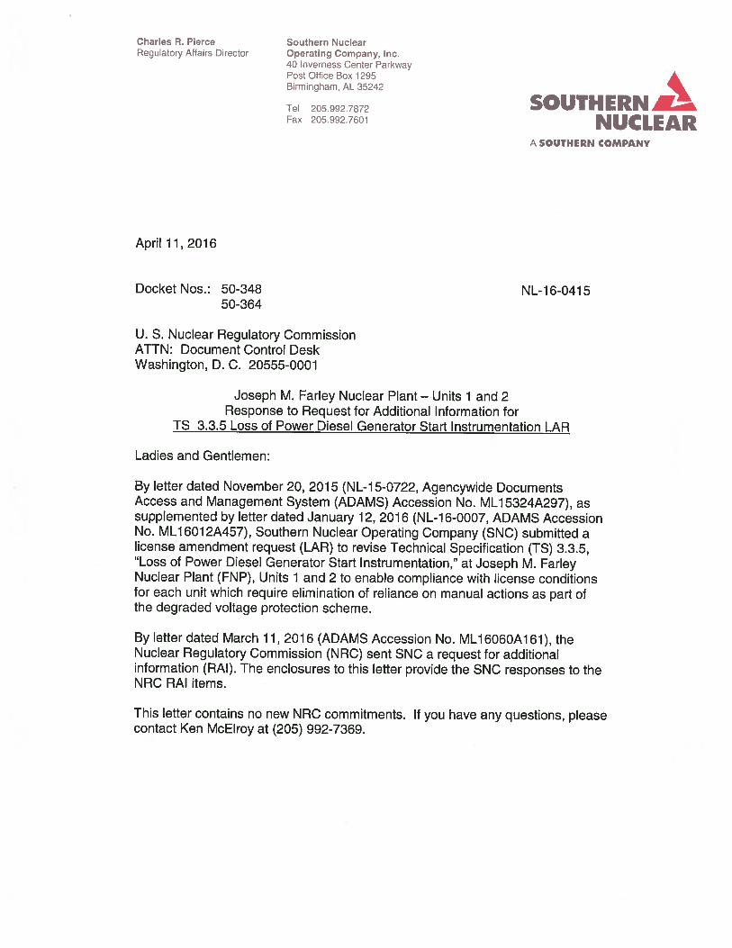
See Table 4.a below for an example of how the LAL being above the MRV ensures approximately 0.65% voltage margin at limiting components. The voltage range between the LAL and MRV, referred to as "DVR Margin" in SE-SNC529029-001 and SE-SNC529029-002 Table 1 a, diminishes the risk that future plant modifications which add load to the safety-related buses would require updates to the LAL and thereby to the TS 3.3.5 values for the DVRs. An example of the LAL, MRV, and limiting component voltages follows in Figure 4.a below.
E1-7
Enclosure 1 to NL-16-0415 SNC Response to RAis
Table 4.a- Example Voltage Analysis Comparing LAL to MRV for MOV 01 P16MOV3024A and 01 P16MOV3024B
Voltage at LAL Voltage at MRV Voltage at Bus 1 F ( 4.16 kV) 89.57% 88.92% Voltage at MOV 3024A and 30248 (550 V) 73.52%* 72.87% Margin at MOV 3024A and 30248 (550 V) 0.65%* 0.00%
* These voltages are estimated by addmg the voltage Increase at the 4.16 kV bus from the MRV to the LAL (0.65 percent) to the voltage at the MOV terminals
10500%
10000%
9500%
9000%
8500%
8000%
7500%
7000%
Gnd at MEV 10U>O%
'
MEV· 4 16 kV Bus 1F, 93 31%
DVR UAL, 92 76%
' ' ' ' ' '
•••••••• .";"" ::::----__ DVR LAL, 89.57%
X················· -. ' '
MRV: 4.16 kV Bus 1F, 88.92%
""~ ~.ft.. G). . ~
9 ".l
~ .......... .
600V MCC 1U {Pre-Start)
... ...... \
\ \
\ \
\ \
\ \
\ \
\
\
l.Jm1tmg Component. MOV 3024A, 72 87%
cS'q, cr.,., t-~~ ~c
~.r ('.l .... .,(' v Figure 4a
\
"
--e- MEV-Normal
..... .. . MEV-LOCA
- • - MRV-LOCA ST
X DVR UAL
+ DVRLAL
~0 ~~ ~~ ~
Example of voltages at critical buses for normal and LOCA case studies used to determine ' 4.16 kV Bus 1F MEV, MRV, UAL, and LAL, showing MOV 3024A as the limiting component.
E1-8

Enclosure 1 to NL-16-0415 SNC Response to RAis
4.b All loads required for safe shutdown are capable of meeting their design functions at voltages below the DVR LAL. Calculations SE-SNC529029-001 and SE-SNC529029-002, design inputs for SJ-SNC529029-001, determine the MRV at which all necessary safety-related plant equipment can perform its safety function. These calculations evaluate several loading scenarios including a concurrent degraded grid and LOCA group motor start. The MRV at each DVR is below the LAL used to calculate the voltage settings for each DVR, meaning that the DVR will trip prior to the limiting loads reaching their minimum voltage requirement.
If voltage falls below the DVR trip setpoint, the DVR will trip prior to any MOV protective devices. TOL trip times are calculated for each safety-related motor by assuming that each draws locked-rotor current at the motor's minimum starting voltage until the overload relay trips. The minimum of all TOL trip times is selected as the maximum DVR trip time, or upper analytical limit (UAL). The DVR trip time allowable values are then calculated from the UAL and ABB Type 27N relay uncertainties.
Control power fuses are adequately sized to not melt on extended contactor inrush current. Contactors have adequate voltage to pick up at the event initiation. Using MCC 1 U as an example, the highest contactor voltage requirement is 81.20% of 600 V for the volume control tank MOV LCV0115C motor starter. The analyzed LOCA pre-start voltage at MCC 1 U is 86.23% of 600 V and the LOCA steady-state voltage is 85.63% of 600 V, therefore the contactor will pick up to start the MOV. Both of these voltages assume the upstream 4.16 kV Bus 1 F is at the MRV of 88.92%.
4.c As detailed in the "Background" section of the LAR description, the existing FNP degraded voltage protection scheme credits operator actions in response to declining voltage to avoid or minimize the occurrence of degraded voltage conditions. The November 21, 1995 Safety Evaluation Report (SEA) that accepted this protection scheme relied in part on a commitment by SNC to include the degraded grid voltage alarms, which would alert the operators to degrading voltage conditions, in the Improved Technical Specifications (ITS) conversion then in preparation, even though these alarms do not otherwise meet the criteria of 10 CFR 50.36(c)(2)(ii) for inclusion in TS. Function 3, "4.16 kV Emergency Bus Degraded Grid Voltage Alarm," was accordingly added to Table 3.3.5-1 when the ITS was issued on November 30, 1999.
In satisfying the license conditions issued to FNP by License Amendments No. 194 and No. 190 (for Units 1 and 2, respectively) by letter dated May 13, 2014 (ADAMS Accession No. ML 14069A344), the proposed LAR eliminates manual actions in lieu of automatic degraded voltage protection, thus warranting the return of the Degraded Voltage alarm function to non-TS status and thereby restoring consistency with the NUREG-1431 Standard Technical Specifications. The purpose of the Degraded Voltage alarm is not affected by this change and it will continue to fulfill the function of alerting operators to sustained degraded voltage conditions.
E1-9

Enclosure 1 to NL-16-0415 SNC Response to RAis
The high level operator actions which are to be taken if the Degraded Grid alarm is actuated are provided by Annunciator Response Procedure (ARP) and Abnormal Operating Procedure (AOP) guidance as summarized below. No revision to ARP or AOP guidance is needed with implementation of the proposed LAR.
If the "4KV BUS OV-OR-UV OR LOSS OF DC" annunciator alarms on either the F or G 4.16 kV emergency buses for either unit, the control room team would refer to the appropriate ARP guidance, determine the cause of the alarm, verify any automatic action, and take the applicable operator actions.
The ARP high level actions performed by the control room team for a Degraded Grid condition are as follows: • Determine cause of alarm. • Refer to abnormal operating procedure AOP-5.2, Degraded Grid. • Return electrical and component lineups to normal as soon as possible.
Applicable items per AOP-5.2 guidance include: • Check Power Control Center (PCC) Notification issued. • Log abnormal condition in Control Room Log. • Check status of F and G 4.16 kV buses and perform applicable actions. • Verify all Emergency Diesel Generators aligned for auto start. • Restore out of service major plant components. • Suspend work activities in the Low Voltage and High Voltage Switchyards • Evaluate effects on non-safety related buses and equipment. • Consult Operations Manager to evaluate continued plant operation. • Contact Alabama Control Center (ACC) for voltage control strategies. • Check status of F and G 4.16 kV Buses. • Evaluate need for plant shutdown (refer toTS 3.3.5, action F.1) • Evaluate need for plant cooldown (refer to TS 3.3.5, action F.2)
RAI No.5
In Section 2.0 "Detailed Description," of the LAR, the licensee provided the proposed changes to Table 3.3.5-2. The licensee noted that this table differs from the current TS Table 3.3.5-1 as follows:
a. Function 1, "4.16 kV Emergency Bus Loss of Voltage DG Start' and Function 2, "4.16 kV Emergency Bus Degraded Grid Voltage Actuation," has the Trip Setpoint column replaced by a new Delay Time column,
b. Function 2 has the singular Allowable Value (AV) voltage range specified for all buses replaced with new AV lower limits specified for each 4.16 kV bus (1 F, 1 G, 2F and 2G), and
c. Function 3, "4.16 kV Emergency Bus Degraded Grid Voltage Alarm," is deleted.
E1-10

Enclosure 1 to NL-16-0415 SNC Response to RAis
NUREG-0800, "Standard Review Plan (SRP) for the Review of Safety Analysis Reports for Nuclear Power Plants," Appendix 8-A, "Branch Technical Position (PSB) PSB-1: Adequacy of Station Electric Distribution System Voltages," states that the licensee's analysis must show that the existing setpoints and time delays are adequate to ensure that all safety-related loads are protected and all required safety-related loads have the required minimum voltage at the component terminal to start and run to support a worst-case design basis event (DBE) without any credit for administratively controlled voltage. PSB-1 states the following:
"Two separate time delays shall be selected for the second level of undervoltage protection ... "
''The Technical Specifications shall include limiting conditions for operations, surveillance requirements, trip setpoints with minimum and maximum limits, and allowable values for the second-level voltage protection sensors and associated time delay devices."
Based on PSB-1 and as pertaining to trip setpoints, and alarms, please respond to the following questions:
1. Function 1, "4.16 kV Emergency Bus Loss of Voltage DG Start' and Function 2, "4.16 kV Emergency Bus Degraded Grid Voltage Actuation," has the Trip Setpoint column replaced by a new Delay Time column that only displays one time delay. Please explain how: a) FNP is complying with PSB-1 in regards to the use of two time delays, and b) provide technical and regulatory bases for deleting the trip setpoint column from the Technical Specifications.
2. Function 3, "4.16 kV Emergency Bus Degraded Grid Voltage Alarm," is deleted from the TS. Please explain how FNP is complying with PSB-1 in regards to the deletion of the 4.16 kV Emergency Bus Degraded Grid Voltage Alarm from the Technical Specifications.
SNC Response to RAI No. 5:
5.1.a The full text from the pertinent portions of PSB-1, section B.1 is as follows:
"b) Two separate time delays shall be selected for the second level of undervoltage protection based on the following conditions:
1) The first time delay should be of a duration that established the existence of a sustained degraded voltage condition (i.e., something longer than a motor starting transient). Following this delay, an alarm in the control room should alert the operator to the degraded condition. The subsequent occurrence of a safety injection actuation signal (SIAS) should immediately separate the Class 1 E distribution system from the offsite power system,
E1-11
Enclosure 1 to NL-16-0415 SNC Response to RAis
2) The second time delay should be of a limited duration such that the permanently connected Class 1 E loads will not be damaged. Following this delay, if the operator has failed to restore adequate voltages, the Class 1 E distribution system should be automatically separated from the offsite power system. Bases and justification must be provided in support of the actual delay chosen."
From the full PSB-1 text reproduced above it can be seen that the first time delay referred to pertains to providing an alarm to alert the operator of a degraded voltage condition. This requirement is met by Function 3, "4.16 kV Emergency Bus Degraded Grid Voltage Alarm" in Table 3.3.5-1 of the current TS. While Function 3 is deleted from the new Table 3.3.5-2 proposed by the LAR, the degraded grid alarm itself will remain in service and operator actions in response to alarm actuation will remain unchanged (refer to the response to RAI 4.c for details of these operator actions).
The second time delay referred to by PSB-1 pertains to providing for automatic separation from the offsite power system. This requirement is met by Function 2, "4.16 kV Emergency Bus Degraded Grid Voltage Actuation" in both the current Table 3.3.5-1 and in the proposed new Table 3.3.5-2.
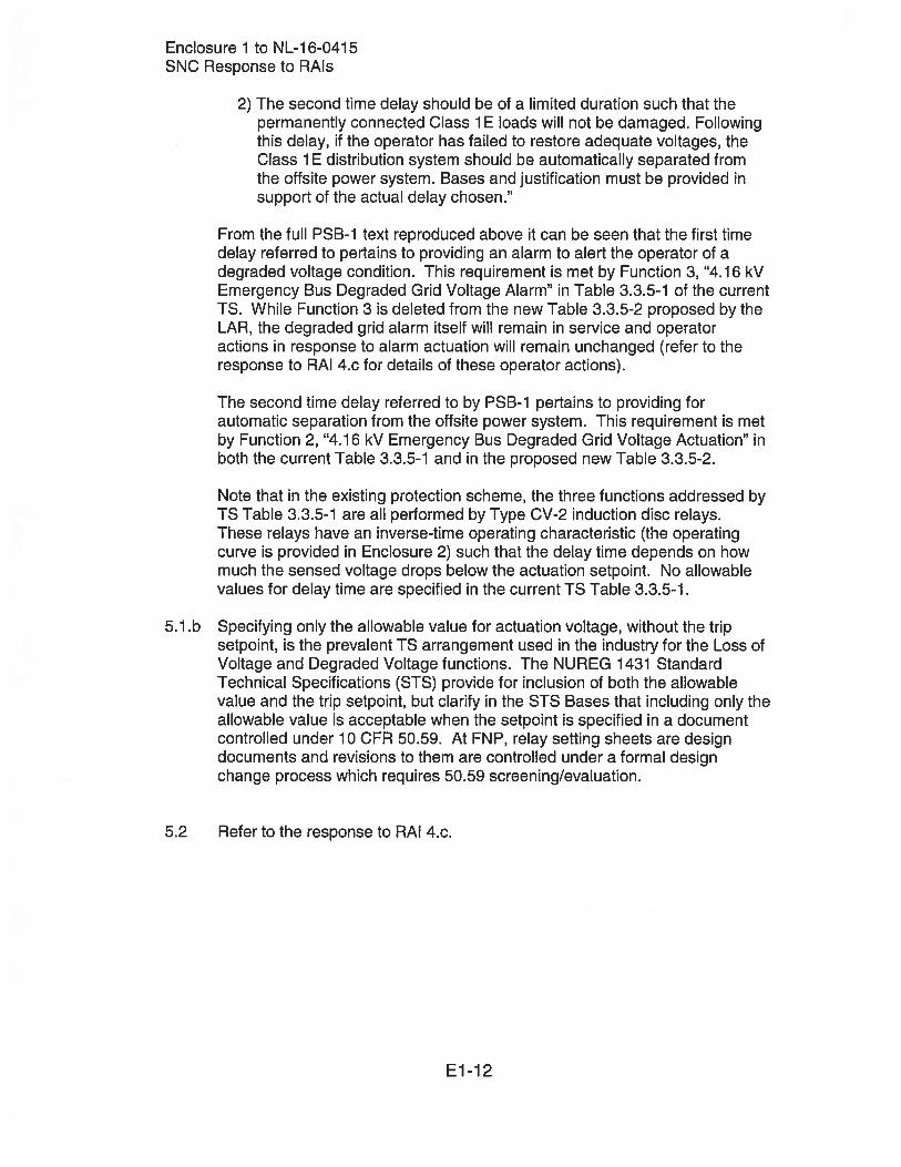
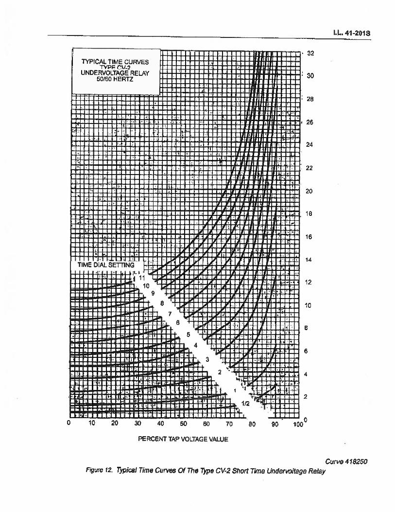
Note that in the existing protection scheme, the three functions addressed by TS Table 3.3.5-1 are all performed by Type CV-2 induction disc relays. These relays have an inverse-time operating characteristic (the operating curve is provided in Enclosure 2) such that the delay time depends on how much the sensed voltage drops below the actuation setpoint. No allowable values for delay time are specified in the current TS Table 3.3.5-1.
5.1.b Specifying only the allowable value for actuation voltage, without the trip setpoint, is the prevalent TS arrangement used in the industry for the Loss of Voltage and Degraded Voltage functions. The NUREG 1431 Standard Technical Specifications (STS) provide for inclusion of both the allowable value and the trip setpoint, but clarify in the STS Bases that including only the allowable value is acceptable when the setpoint is specified in a document controlled under 10 CFR 50.59. At FNP, relay setting sheets are design documents and revisions to them are controlled under a formal design change process which requires 50.59 screening/evaluation.
5.2 Refer to the response to RAI 4.c.
E1-12

Joseph M. Farley Nuclear Plant Response to Request for Additional Information for
TS 3.3.5 Loss of Power Diesel Generator Start Instrumentation LAR
Enclosure 2
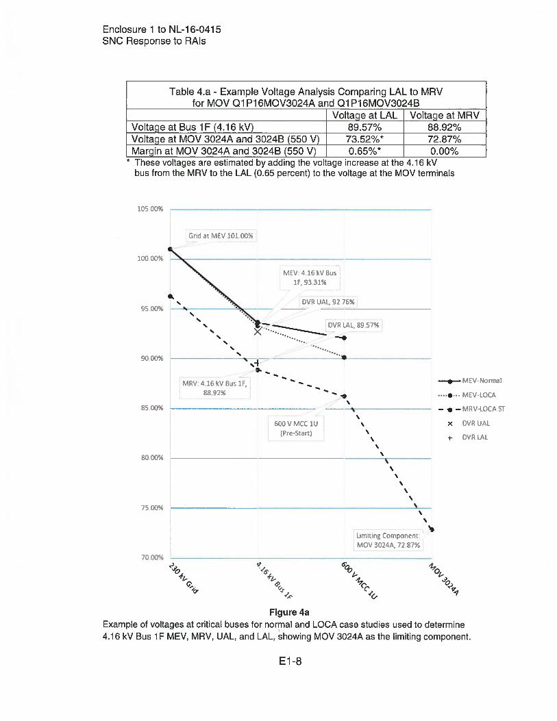
Type CV-2 and Type 27N Undervoltage Relay Operating Curves (Excerpts from ABB Type CV Voltage Relay Instruction Leaflet 41-201 S
and ABB Single Phase Voltage Relays Instruction Bulletin 7.4.1.7-7)
TYPICAL itME CURVES TVPF! Cj/. '2
UNDERVOLTAGE RELAY 50f60 HERTZ
.. . . .. . .. . . I
• .. •I ' ~ - - ': .
'· • 'I • f •
J *. - .,
...
. I
: I . . . .. ~. . .. .. . , .
..
, . . . ..
.. . ..
. ~ . . -· . .
' . !• . • - "" I
. I
. . . .. .. . ' . . J ·. ,.
. ; ' . ; . . ... , .... .
.! ·' . ' ... TIME OtAL'smN7t " ...,_ ._,~....,: ~- '-'F-t-41114~~1'H.III· ~f-!1· ..o+-j~l"',... -t·:JIIIII-tl-~-....'-+'..,: If-+ .. +:*-.+.-tr+~
• • :t. J • . . • 11
I.L. 41-2018
. 32
. 30 .
28
i 26
24
22
20
18
16
14
12
~~~~~~~~1~0 9
. . . ' ' l ...
10
0
~ . . ' I ' 0 t 'i
. ' ' . 1 I a .- • ! •
0 •• • - ;.t ,· '' • I I
• 1 -
10 20 30 40 50 60 70 80 90
PERCENT TAP VOLTAGE VALUE
Curve 418250 Figvre 12. Typical Time Curves Of The Type CV-2 Short Time Undervoltage Relay

• • 1: • 0 • • I ,.. c ~ ., 0 .. :1 -~
TIME VOLTAGE CHARACTERISTICS
TYPE 27N UNDERVOL T AGE RELAY DEFINITE TIME
1.2 ---...... ------------....----....-----
I 1.0~-----+~----.. ------~----~~--~--~-----i
0.1
0.1
o.•
0.2
0 D
s
•
3
2
,
0.2 0.4 o.• Q.l t.D
MUL TePLEI ot DROPOUT lETTING
SHORT TIME Catalog S•rtee 211TI••• and •11TtKX• TIME DELAY AS IHOMN
MEDIUM TIME Catalov S•rtee Z1tT•axx and •1tT•xxa MU~TIPLY TI~E DELAY IHOMN tV 10
1.2
~ ... , ... I I TVC IOINO

Joseph M. Farley Nuclear Plant Response to Request for Additional Information for
TS 3.3.5 Loss of Power Diesel Generator Start Instrumentation LAR
Enclosure 3
In-Process Revision to FSAR 8.2.2.4 (Excerpt from LDCR No. 2015-022)

DCP SNC602932 LDCR No. 2015-{)22 Page l of4
FNP-FSAR-8
operation. Offsite power system voltage is not intentionally lowered below the 101.6% voltage level because some nonsafety-related loads are not analyzed for operation below 101 .6%. System voltages for worst-case single contingencies are expected to remain at or above 400Jjll% of 230 kV. This includes the contingency that assumes one Farley unit is in a LOCA and the other unit is tripped. The value of 4-00J.W.% assures acceptable terminal voltages. with margin, for safe shutdown equipment to perform its safety function. Therefore, continued unit operation is acceptable in the unlikely event that system voltage is found to be< 101.6% but above .:j.Q.Q. J01 %. Voltages> 104.5% are allowed as long as 4160-V bus voltage levels do not cause equipment maximum voltage ratings to be exceeded.
Periodic transmission system planning studies are performed to help ensure that voltages can be maintained within acceptable limits.
8.2-6 REV25 4114