Embed Size (px)
Citation preview

IInnssttaallllaattiioonn,,OOppeerraattiioonn,,
&& MMaaiinntteennaanncceeMMaannuuaall
U.S. PATENT NO’S:
5,865,426, 6,299,139,
& 6,386,513
OTHER PATENTS
PENDING
EEaassyy AArrmm®®FFlloooorr MMoouunntteeddGorbel® Dealer __________________________
Serial Number ___________________________
Gorbel® Customer Order No. ______________
Date ___________________________________
®
™
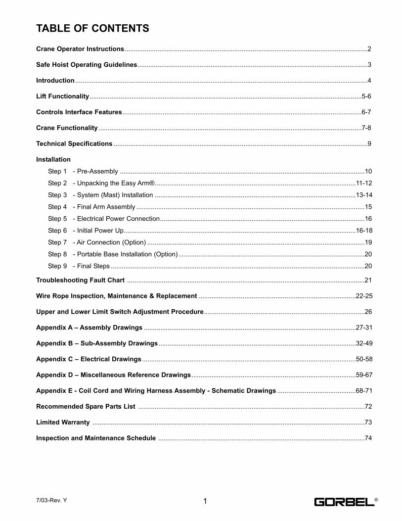
TABLE OF CONTENTS
Crane Operator Instructions.....................................................................................................................................2
Safe Hoist Operating Guidelines..............................................................................................................................3
Introduction ................................................................................................................................................................4
Lift Functionality.....................................................................................................................................................5-6
Controls Interface Features...................................................................................................................................6-7
Crane Functionality ................................................................................................................................................7-8
Technical Specifications ...........................................................................................................................................9
Installation
Step 1 - Pre-Assembly ......................................................................................................................................10
Step 2 - Unpacking the Easy Arm®..............................................................................................................11-12
Step 3 - System (Mast) Installation ..............................................................................................................13-14
Step 4 - Final Arm Assembly .............................................................................................................................15
Step 5 - Electrical Power Connection................................................................................................................16
Step 6 - Initial Power Up...............................................................................................................................16-18
Step 7 - Air Connection (Option) .......................................................................................................................19
Step 8 - Portable Base Installation (Option)......................................................................................................20
Step 9 - Final Steps ...........................................................................................................................................20
Troubleshooting Fault Chart ..................................................................................................................................21
Wire Rope Inspection, Maintenance & Replacement ......................................................................................22-25
Upper and Lower Limit Switch Adjustment Procedure........................................................................................26
Appendix A – Assembly Drawings ....................................................................................................................27-31
Appendix B – Sub-Assembly Drawings ............................................................................................................32-49
Appendix C – Electrical Drawings .....................................................................................................................50-58
Appendix D – Miscellaneous Reference Drawings..........................................................................................59-67
Appendix E - Coil Cord and Wiring Harness Assembly - Schematic Drawings ...........................................68-71
Recommended Spare Parts List ............................................................................................................................72
Limited Warranty .....................................................................................................................................................73
Inspection and Maintenance Schedule .................................................................................................................74
17/03-Rev. Y ®
CRANE OPERATOR INSTRUCTIONSOverhead cranes and jib cranes generally handle materials over working areas where there are personnel. Therefore, it is important for the Crane Operator to be
instructed in the use of the crane and to understand the severe consequences of careless operation.
It is not intended that these suggestions take precedence over existing plant safety rules and regulations or OSHA regulations. However, a thorough study of the
following information should provide a better understanding of safe operation and afford a greater margin of safety for people and machinery on the plant floor.
It must be recognized that these are suggestions for the Crane Operator’s use. It is the responsibility of the owner to make personnel aware of all federal, state and
local rules and codes, and to make certain operators are properly trained.
Qualifications
Crane operation, to be safe and efficient, requires skill: the exercise of extreme care and good judgment, alertness and concentration, and rigid adherence to proven
safety rules and practices as outlined in applicable and current ANSI and OSHA safety standards. In general practice, no person should be permitted to operate a
crane:
• Who cannot speak the appropriate language or read and understand the printed instructions.
• Who is not of legal age to operate this type of equipment.
• Whose hearing or eyesight is impaired (unless suitably corrected with good depth perception).
• Who may be suffering from heart or other ailments which might interfere with the operator’s safe performance.
• Unless the operator has carefully read and studied this operation manual.
• Unless the operator has been properly instructed.
• Unless the operator has demonstrated his instructions through practical operation.
• Unless the operator is familiar with hitching equipment and safe hitching equipment practices.
Handling the Jib Arm Motion
Before using the jib crane, the operator should be sure the hook is high enough to clear any obstruction. Before a load is handled by the crane, the jib boom should be
brought into position so that it is directly over the load. Start the jib boom slowly and bring it up to speed gradually. Approaching the place where it is desired to stop
the jib, reduce the boom speed.
Handling the Hoist Motion
Refer to the lifting (hoist) equipment’s operating instructions.
GENERAL SUGGESTIONS
Know Your Crane
Crane operators should be familiar with the principal parts of a crane and have a thorough knowledge of crane control functions and movements. The crane operator
should be required to know the location and proper operation of the main conductor disconnecting means for all power to the attachments on the crane.
Responsibility
Each crane operator should be held directly responsible for the safe operation of the crane. Whenever there is any doubt as to SAFETY, the crane operator should
stop the crane and refuse to handle loads until: (1) safety has been assured or (2) the operator has been ordered to proceed by the supervisor, who then assumes all
responsibility for the SAFETY of the lift.
Do not permit ANYONE to ride on the hook or a load.
Inspection
Test the crane movement and any attachments on the crane at the beginning of each shift. Whenever the operator finds anything wrong or apparently wrong, the prob-
lem should be reported immediately to the proper supervisor and appropriate corrective action taken.
Operating Suggestions
One measure of a good crane operator is the smoothness of the crane operation. The good crane operator should know and follow these proven suggestions for safe,
efficient crane handling.
1. The crane should be moved smoothly and gradually to avoid abrupt, jerky movements of the load. Slack must be removed from the sling and hoisting ropes
before the load is lifted.
2. Center the crane over the load before starting the hoist to avoid swinging the load as the lift is started. Loads should not be swung by the crane to reach areas
not under the crane.
3. Crane-hoisting ropes should be kept vertical. Cranes shall not be used for side pulls.
4. Be sure everyone in the immediate area is clear of the load and aware that a load is being moved.
5. Do not make lifts beyond the rated load capacity of the crane, sling chains, rope slings, etc.
6. Make certain that before moving the load, load slings, load chains, or other lifting devices are fully seated in the saddle of the hook with hook latch closed (if
equipped with hook latch).
7. Check to be sure that the load and/or bottom block is lifted high enough to clear all obstructions when moving boom or trolley.
8. At no time should a load be left suspended from the crane unless the operator has the push button with the power on, and under this condition keep the load as
close as possible to the floor to minimize the possibility of an injury if the load should drop. When the crane is holding a load, the crane operator should remain
at the push button.
9. Do not lift loads with sling hooks hanging loose. If all sling hooks are not needed, they should be properly stored, or use a different sling.
10. All slings or cables should be removed from the crane hooks when not in use (dangling cables or hooks hung in sling rings can inadvertently snag other objects
when the crane is moving).
11. Operators shall not carry loads and/or empty bottom blocks over personnel. Particular additional caution should be practiced when using magnet or vacuum
devices. Loads or parts of loads, held magnetically could drop. Failure of power to magnets or vacuum devices can result in dropping the load. Extra precaution
should be exercised when handling molten metal in the proximity of personnel.
12. Whenever the operator leaves the crane the following procedure should be followed:
• Raise all hooks to an intermediate position.
• Spot the crane at an approved designated location.
• Place all controls in the “off” position.
• Open the main switch to the “off” position.
• Make visual check before leaving the crane.
13. In case of emergency or during inspection, repairing, cleaning or lubrication, a warning sign or signal should be displayed and the main switch should be locked
in the “off” position. This should be done whether the work is being done by the crane operator or by others.
14. Contact with rotation stops or trolley end stops shall be made with extreme caution. The operator should do so with particular care for the safety of persons
below the crane, and only after making certain that any persons on the other cranes are aware of what is being done.
15. ANY SAFETY FEATURES AND MECHANISMS BUILT IN OR OTHERWISE PROVIDED WITH THE CRANE BY GORBEL ARE REQUIRED FOR THE SAFE
OPERATION OF THE CRANE. DO NOT, UNDER ANY CIRCUMSTANCES, REMOVE OR OTHERWISE IMPAIR OR DISABLE THE PROPER FUNCTIONING
OF ANY CRANE SAFETY MECHANISMS OR FEATURES BUILT-IN OR OTHERWISE PROVIDED BY GORBEL FOR SAFE OPERATION OF THE CRANE.
ANY REMOVAL, IMPAIRMENT OR DISABLING OF ANY SUCH SAFETY MECHANISMS OR FEATURES OR OTHER USE OR OPERATION OF THE CRANE
WITHOUT THE COMPLETE AND PROPER FUNCTIONING OF ANY SUCH SAFETY MECHANISMS OR FEATURES AUTOMATICALLY AND IMMEDIATELY
VOIDS ANY AND ALL EXPRESS AND IMPLIED WARRANTIES OF ANY KIND OR NATURE.
2 7/03-Rev. Y®
SAFE HOIST OPERATING GUIDELINESGeneral
There is no one single factor that is more important for minimizing
the possibility of personal injury to the operator and those working
in the area, or damage to property, equipment, or material, than
being familiar with the equipment and using Safe Operating
Practices.
Hoist/trolleys are designed for lifting and transporting of material
only. Under no circumstances, either during initial installation or in
any other use, should the hoist be used for lifting or transporting
personnel.
No operator should be permitted to use the equipment that is not
familiar with its operation, is not physically or mentally fit, or has
not been schooled in safe operating practices. The misuse of
hoists can lead to certain hazards which cannot be protected
against by mechanical means; hazards which can only be avoided
by the exercise of intelligence, care, and common sense.
Safe Operating Practices also involve a program of periodic
inspection and preventative maintenance (covered in separate
section). Part of the operator’s training should be an awareness of
potential malfunctions/hazards requiring adjustments or repairs,
and bringing these to the attention of supervision for corrective
action.
Supervision and management also have an important role to play
in any safety program by ensuring that a maintenance schedule is
adhered to, and that the equipment provided for the operators is
suitable for the job intended without violation of one or more of the
rules covering safe operating practices and good common sense.
The Safe Operating Practices shown are taken in part from the
following publications:
• American National Standard Institute (ANSI)
• Safety Standards for Cranes, Derricks, Hoists
• ANSI B30.2 - Overhead and Gantry Cranes
• ANSI B30.16 - Overhead Hoist
Do’s and Don’ts (Safe Operation of Hoists)
The following are Do’s and Don’ts for safe operation of overhead
hoists. A few minutes spent reading these rules can make an
operator aware of dangerous practices to avoid and precautions to
take for his own safety and the safety of others. Frequent
examinations and periodic inspections of the equipment as well as
a conscientious observance of safety rules may save lives as well
as time and money.
DON’TS – HOISTS
1. Never lift or transport a load until all personnel are clear and
do not transport the load over personnel.
2. Do not allow any unqualified personnel to operate hoist.
3. Never pick up a load beyond the capacity rating appearing on
the hoist. Overloading can be caused by jerking as well as
by static overload.
4. Never carry personnel on the hook or the load.
5. Do not operate hoist if you are not physically fit.
6. Do not operate hoist to extreme limits of travel of cable
without first checking for proper limit switch action.
7. Avoid sharp contact between two hoists or between hoist and
end stops.
8. Do not tamper with or adjust any parts of the hoist unless
specifically authorized to do so.
9. Never use the load cable as a sling.
10. Do not divert attention from load while operating hoist.
11. Never leave a suspended load unattended.
12. Do not use limit switch(es) for normal operating stop(s).
These are safety devices only and should be checked on a
regular basis for proper operation.
13. Never operate a hoist that has an inherent or suspected
mechanical or electrical defect.
14. Do not use load cable as ground for welding. Never touch a
live welding electrode to the load cable.
15. Do not jog controls unnecessarily. Hoist motors are generally
high torque, high slip types. Each start causes an inrush of
current greater than the running current and leads to over-
heating and heat failure, or burnout, if, continued to excess.
16. Do not operate hoist if load is not centered under hoist.
17. Do not operate hoist if cable is twisted, kinked or damaged.
18. Do not remove or obscure label.
19. Do not permanently activate dead man’s switch.
DO’S – HOISTS
1. Read and follow manufacturer’s instruction, installation, and
maintenance manuals. When repairing or maintaining a
hoist, use only manufacturer’s recommended parts and
materials.
2. Read and follow all instruction and warning information on or
attached to a hoist.
3. Remove the hoist from service and thoroughly inspect and
repair, as necessary, if unusual performance or visual defects
(such as peculiar noise, jerky operations, travel in improper
direction, or obviously damaged parts) are noticed.
4. Establish a regular schedule of inspection and maintain
records for all hoists with special attention given to hooks,
load cables, brakes, and limit switches.
5. Check operation of brakes for excessive drift.
6. Never lift loads over people, etc.
7. Check for damaged hooks and load cable.
8. Keep load cable clean and well maintained.
9. Check the load cable for improper seating, twisting, kinking,
wear, or other defects before operating the hoists.
10. Make sure a load clears neighboring stockpiles, machinery, or
other obstructions when raising, lowering, or traveling the
load.
11. Center hoist over the load before operating.
12. Avoid swinging of load or load hook when traveling the hoist.
13. Be sure the load attachment is properly seated in the saddle
of the hook. Balance load properly before handling. Avoid
hook tip loading.
14. Pull in a straight line, so that neither hoist body nor load cable
are angled around an object.
15. Take up slack slowly.
16. Know the hand signals for hoisting, cross travel, and crane
travel if working with cab-operated hoists or cranes.
Operators should accept the signals of only those persons
authorized to give them.
37/03-Rev. Y ®
INTRODUCTION
Thank you for choosing a Gorbel® Easy Arm® Crane** to solve your material handling needs. The innovative
design and heavy-duty construction of the Gorbel® Easy Arm® will provide a superior quality product that will offer
years of long term value. Gorbel® Easy Arm® Cranes will provide many years of dependable service by following
the installation and maintenance procedures described herein.
** U.S. PATENT NO’S: 5,865,426, 6,299,139 & 6,386,513, OTHER PATENTS PENDING
Dimensions contained in this installation manual are for reference only and may differ for your particularapplication. Please refer to the enclosed General Arrangement Drawing for actual dimensions.
Normal safety precautions: These include, but are not limited to:
• Checking for obstructions in crane and hoist travel
• Checking that all bolts are tight and have lockwashers
WARNING Only competent erection personnel familiar with standard fabrication practices should be employed to
assemble these cranes because of the necessity of properly interpreting these instructions. Gorbel is not
responsible for the quality of workmanship employed in the installation of a crane according to these
instructions. Contact Gorbel, Inc., at 600 Fishers Run, P.O. Box 593, Fishers, New York 14453, 1-585-924-
6262, for additional information, if necessary.
WARNING Equipment described herein is not designed for, and should not be used for, lifting, supporting or
transporting humans. Failure to comply with any one of the limitations noted herein can result in serious
bodily injury and/or property damage. Check Federal, State and Local regulations for any additional
requirements.
WARNING Consult a qualified structural engineer to determine if your support structure is adequate to support the
anchor bolt force, overturning moment, or axial load of your crane.
WARNING Crane cannot be utilized as a ground. A separate ground wire is required. For example, systems with 3-
phase power require 3 conductors plus one ground wire.
WARNING Reference American Institute of Steel Construction (AISC) Manual of Steel Construction (9th edition), Part 5,
Specification for Structural Joints using ASTM A325 or A490 Bolts (Section 8.d.2) for proper procedure to
follow when using any torque tightening methods.
WARNING Do not field modify crane in any way. Any modification without the written consent of Gorbel, Inc., will void
warranty.
WARNING The unique serial number for this unit can be found on the front cover of this manual or on a sticker
attached to the back of the Head Assembly. Always have this serial number available during all
correspondence regarding your Easy Arm® crane, or when ordering repair parts.
4 7/03-Rev. Y®
Standard Operation Sliding Handle: The Gorbel® Easy Arm® is an articulating jib crane, servomotor driven lifting
device combination. When the device is in the standard operational mode, the sliding handle of the hand controller
commands the z-axis direction and speed of the lift, while the motion of the articulating crane is manually controlled.
The handle has a center neutral position and can slide up and down to provide up and down speed commands to the
control system. The further the handle is displaced from the neutral position the faster the servo movement to lift or
lower the load. The operator lifts or lowers the load by grasping the handle and moving it up or down as if it were an
extension of the operator’s arm. The lift moves slightly slower when a heavy load is lifted, thereby giving the operator
some feel for the weight of the load and thus reducing inertial forces. When depressed, the operator present switch
in the handle activates the servomotor. Depressing the operator present switch also releases an electrically operated
mechanical failsafe holding brake in the motor.
Standard Operation Pendant Handle: The Gorbel® Easy Arm® is an articulating jib crane with a servomotor
driven lifting device. When the device is in the standard operational mode, the up and down levers command the
z-axis direction and speed of the lift (reference Diagram A) and the motion of the articulating crane is manually
controlled. The more the up and down levers are depressed, the faster the servo movement to raise or lower the load.
The mechanical brake is activated when neither of the levers are depressed.
Overload: The servo controller will prevent the lift from moving upward if loaded beyond the maximum capacity of the
G-Force® lifting device. When an overload condition is sensed the Overload indicator is illuminated and the lift is
prevented from moving upward. The lift may be moved down to allow for the safe removal of the load. Releasing
and reactivating the operator present switch on the sliding handle will reset the overload condition. For the pendant
handle, cycle the power on and off using the E-stop button.
Limit Switches: The crane is equipped with both Upper and Lower Limit switches, located in the Actuator assembly.
When the Upper Limit switch is triggered, the upward motion of the lift stops quickly at a controlled deceleration rate.
The controlled deceleration rate guarantees the load cannot come off the hook. When the Upper Limit is triggered
the lift will move down but not up. The lower limit is set so that a minimum of two full wraps of wire rope remain on the
drum pulley at all times. When the Lower Limit switch is triggered, the downward motion of the lift stops quickly
at a controlled deceleration rate. When the Lower Limit is triggered the lift will only move up and not down.
Slack Switch: The crane is equipped with a Slack Switch that senses tension in the wire rope and trips when the
wire rope develops slack. The switch is located at the end of the secondary arm. When the Slack Switch senses
slack in the wire rope, downward movement of the lift is stopped to minimize the amount of wire rope unwound from
the drum pulley. When slack in the wire rope is sensed the lift will only move up but not down.
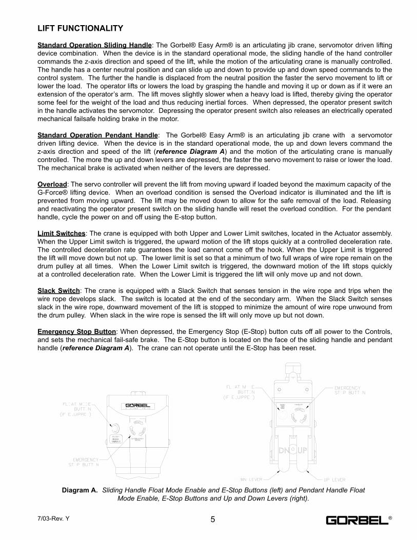
Emergency Stop Button: When depressed, the Emergency Stop (E-Stop) button cuts off all power to the Controls,
and sets the mechanical fail-safe brake. The E-Stop button is located on the face of the sliding handle and pendant
handle (reference Diagram A). The crane can not operate until the E-Stop has been reset.
LIFT FUNCTIONALITY
Diagram A. Sliding Handle Float Mode Enable and E-Stop Buttons (left) and Pendant Handle FloatMode Enable, E-Stop Buttons and Up and Down Levers (right).
57/03-Rev. Y ®
Float Mode (System Option): This mode is initiated by simply pressing the Float Mode Enable button on the sliding
handle or the pendant handle. In this mode, the operator can simply handle the load directly with either one or two
hands and cause the load to raise or lower by applying either an upward or downward force on the load. This mode
overrides the need to depress the operator present switch (sliding handle only). The greater the force applied,
the faster the load will move. There is a standard setting in the controls that safely limits the maximum speed of
travel in Float Mode. Actuating the operator present switch (sliding handle only), Upper Limit switch, Lower Limit
switch, Slack Switch, or depressing and up or down lever (pendant handle only) while in Float Mode will cause the
unit to exit float. While in Float Mode, the load cannot be increased or decreased because this may cause unwanted
motion. Float Mode must be reinitiated each time the weight of the live load is changed.
Remote Mount Handle (System Option): The lifting device is capable of operating with the sliding handle or pendant
handle displaced from the wire rope (not in-line with the wire rope). For example; if an enduser has tooling that is too
large for the operator to safely reach and operate the handle in the standard position, remote mounting the handle is
recommended. The tooling must be mounted (and balanced) on the end of the wire rope, while the handle can be
remote mounted. The tooling must be attached to the end of the wire rope with a swivel assembly (supplied by Gorbel,
Inc.). Failure to mount the tooling with a swivel assembly can result in premature failure of both the wire rope and the
coil cord. The remote mounted handle is linked to the coil cord via extension cables and connectors. The sliding
handle operates exactly the same as if it were mounted in-line and the pendant handle operates the same as if it were
suspended. If the device is equipped for Float Mode, a load cell assembly is provided that must also be mounted
between the tooling and the end of the wire rope. The handle is linked to the load cell via an extension cable and
connectors. **The end user must supply Gorbel with the required length of the extension cables such that they can
be safely routed and clamped to the tooling. When providing the extension length always include bends and turns.
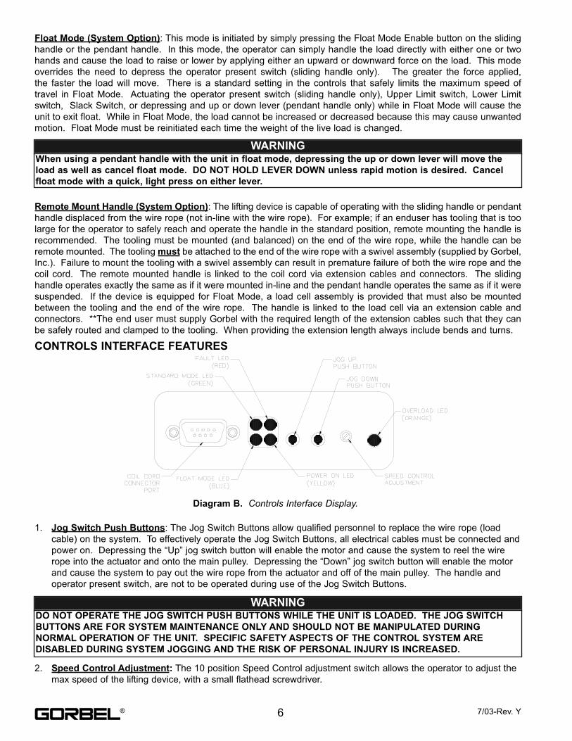
1. Jog Switch Push Buttons: The Jog Switch Buttons allow qualified personnel to replace the wire rope (load
cable) on the system. To effectively operate the Jog Switch Buttons, all electrical cables must be connected and
power on. Depressing the “Up” jog switch button will enable the motor and cause the system to reel the wire
rope into the actuator and onto the main pulley. Depressing the “Down” jog switch button will enable the motor
and cause the system to pay out the wire rope from the actuator and off of the main pulley. The handle and
operator present switch, are not to be operated during use of the Jog Switch Buttons.
2. Speed Control Adjustment: The 10 position Speed Control adjustment switch allows the operator to adjust the
max speed of the lifting device, with a small flathead screwdriver.
6 7/03-Rev. Y
Diagram B. Controls Interface Display.
CONTROLS INTERFACE FEATURES
WARNING DO NOT OPERATE THE JOG SWITCH PUSH BUTTONS WHILE THE UNIT IS LOADED. THE JOG SWITCH
BUTTONS ARE FOR SYSTEM MAINTENANCE ONLY AND SHOULD NOT BE MANIPULATED DURING
NORMAL OPERATION OF THE UNIT. SPECIFIC SAFETY ASPECTS OF THE CONTROL SYSTEM ARE
DISABLED DURING SYSTEM JOGGING AND THE RISK OF PERSONAL INJURY IS INCREASED.
WARNING When using a pendant handle with the unit in float mode, depressing the up or down lever will move the
load as well as cancel float mode. DO NOT HOLD LEVER DOWN unless rapid motion is desired. Cancel
float mode with a quick, light press on either lever.
®
3. Power On LED (Yellow): The “Power On” LED illuminates when the required 220VAC, single-phase power has
been correctly applied to the system.
4. Standard Mode LED (Green): The “Standard Mode” LED illuminates when all system initialization is complete
and the operator present switch is depressed, thus activating the standard mode of operation.
5. Capacity Overload LED (Orange): The “Capacity Overload” LED illuminates when a load or impact load
greater than the capacity of the hoist has been detected by the system. When this LED illuminates, the
controller will allow the operator to lower the load, but it will inhibit the operator from raising the load prior to
“resetting” the system. To clear the overload fault and “reset” the system, release the switch for approximately 1
to 2 seconds. Once the LED turns off, the system can again be operated.
6. Float Mode Enabled LED (Blue): If the unit is equipped with Float Mode (system option), the “Float Mode
Enabled” LED will illuminate when the Float Mode Enable button is pressed on the hand controller and Float
Mode has been initiated.
7. System Fault LED (Red): The “System Fault” LED flashes when basic faults have been detected by the control
system. If a fault has occurred the “Standard Mode” or “Float Mode”(if equipped) LED’s will turn off. The
“System Fault” LED flashes a simple code when a fault has occurred. The sequence of flashes indicates the
type of fault. The sequence consists of a number of short flashes followed by a long pause. The number of
short flashes is the key to determining the fault code. For example 3 short flashes followed by a long pause
indicates fault code #3. The sequence will continually repeat until the fault is reset.
8. Power Up Diagnostic Mode: When the “E-stop” button is released and power is applied to the lift, the servo motor
controller goes into a power up diagnostic mode test. The following are the sections to the diagnostic mode test:
a) LED Indicator Test: The purpose of this test is to verify the five (5) indicator LED’s are functional. When
the main power is applied, the yellow “Power On” LED comes on immediately indicating the internal 24
volt power is operational. After the servo controller completes a series of self-tests, it turns on the (4)
remaining LED’s for 2 seconds to simply verify functionality.
b) Switch Test: After completion of the indicator test, a system switch test is started. The purpose of this
test is to display the state of the “Slack” switch and “Upper and Lower Limit” switches. During the switch
test, the orange “Overload” LED will flash if the “Upper Limit” switch is triggered (up limit state) and the
blue “Float Mode” LED will stay on if the “Slack” switch is triggered (wire rope slack). Once the operator
present switch or jog switch is activated the servo motor controller exits the power up diagnostic mode and
goes into normal operation.
NOTE: The yellow Power On indicator will remain on during the power up diagnostic mode test.
CRANE FUNCTIONALITY
Standard Assembly: The Easy Arm® crane consists of (7) main assemblies, and they are as follows:
1) Mast: Mounted directly to a minimum 6” deep floor with 3/4” diameter anchor bolts, the mast is the main
mounting structure for the Easy Arm®. The mast also provides the entrance point for both power and air
(system option) to the crane.
2) Head: The Head assembly is the main system pivoting assembly mounted directly to the mast pin at the
top of the mast. Both the Actuator and Primary Arm assemblies mount directly to the Head assembly. The
Head assembly utilizes double sealed radial ball bearings for rotation and does not need to be greased.
The Head assembly is capable of 375 degrees of rotation, achieved through the use of a swinging end
stop arm that is located on the front face of the pivoting block between the side plates. The Head
assembly is equipped with a Friction Brake the mounts between the head pivot block and the mast pin
located on the mast. This allows the operator to adjust the friction on the main mast pin, therefore
controlling the speed and rotation of the Head Arm assembly.
3) Primary Arm: The Primary Arm assembly mounts directly to the Head assembly, and is also attached to
the Secondary Arm assembly at the pivot knuckle. The Primary Arm is also the location of the Primary
Arm Adjustment assembly. The Primary Arm Adjustment assembly is mounted between the bottom of the
Primary Arm and the side plates of the Head assembly. During installation of the crane, the enduser has
the ability to adjust the level of the arms on the system to eliminate unnecessary drift when the system is
unloaded. The Primary Arm is also equipped with a Friction Brake that can be adjusted to control the
speed and rotation of the secondary arm during operation. The Primary Arm also utilizes double sealed
radial ball bearings for rotation and does not need to be greased.
77/03-Rev. Y ®
4) Secondary Arm: The Secondary Arm assembles directly to the end of the Primary Arm. The Secondary
Arm assembly contains the “Slack-Pulley” assembly. The “Slack-Pulley” assembly contains a switch that
sends a signal to the controls when slack in the wire rope is detected. This switch prevents excess wire
rope from spooling off of the main drum pulley in the Actuator assembly. The “Slack-Pulley” is also the
transition element that changes the travel of the wire rope from horizontal to vertical. The Coil Cord
assembly also mounts up to the end of the Secondary Arm. When the Secondary Arm is installed, the
Idler Pulley Pivot assembly is also installed at the knuckle of both arms. The Idler Pulley Pivot assembly
allows the operator to rotate both arms without worry of damaging the wire rope.
5) Actuator: The Actuator assembly contains the main lifting power transmission of the Easy Arm®. The
drive assembly of the Actuator consists of the ServoMotor with failsafe brake, Gearbox, Main Drum Pulley,
and Controls. The Actuator also contains the Upper and Lower limit switches. See the Lift Functionalityand Controls Interface Feature sections for additional detail.
6) Coil Cord: The Coil Cord assembly carries the signals from the Handle back to the Controls in the
Actuator assembly. The Coil Cord carries signals back to the Controls for lift speed, lift direction, E-Stop,
and Float Mode (if equipped). Caution must be taken to not over-rotate the Handle, as serious damage
can occur when the Coil Cord binds up around the wire rope.
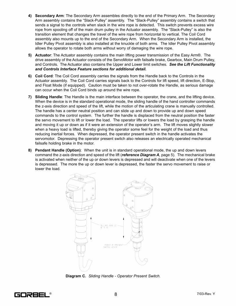
7) Sliding Handle: The Handle is the main interface between the operator, the crane, and the lifting device.
When the device is in the standard operational mode, the sliding handle of the hand controller commands
the z-axis direction and speed of the lift, while the motion of the articulating crane is manually controlled.
The handle has a center neutral position and can slide up and down to provide up and down speed
commands to the control system. The further the handle is displaced from the neutral position the faster
the servo movement to lift or lower the load. The operator lifts or lowers the load by grasping the handle
and moving it up or down as if it were an extension of the operator’s arm. The lift moves slightly slower
when a heavy load is lifted, thereby giving the operator some feel for the weight of the load and thus
reducing inertial forces. When depressed, the operator present switch in the handle activates the
servomotor. Depressing the operator present switch also releases an electrically operated mechanical
failsafe holding brake in the motor.
8) Pendant Handle (Option): When the unit is in standard operational mode, the up and down levers
command the z-axis direction and speed of the lift (reference Diagram A, page 5). The mechanical brake
is activated when neither of the up or down levers is depressed and will deactivate when one of the levers
is depressed. The more the up or down lever is depressed, the faster the servo movement to raise or
lower the load.
Diagram C. Sliding Handle - Operator Present Switch.
8 7/03-Rev. Y®
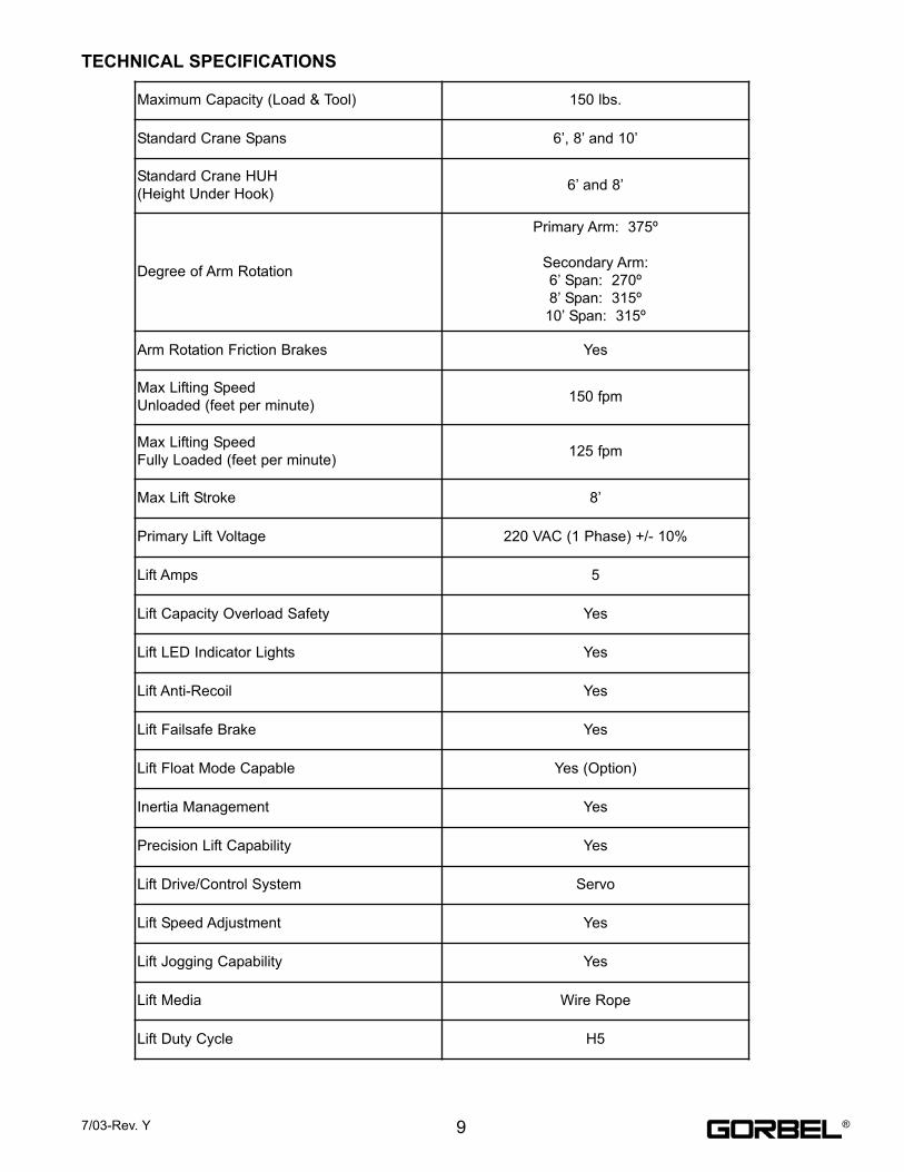
Maximum Capacity (Load & Tool) 150 lbs.
Standard Crane Spans 6’, 8’ and 10’
Standard Crane HUH
(Height Under Hook)6’ and 8’
Degree of Arm Rotation
Primary Arm: 375º
Secondary Arm:
6’ Span: 270º
8’ Span: 315º
10’ Span: 315º
Arm Rotation Friction Brakes Yes
Max Lifting Speed
Unloaded (feet per minute)150 fpm
Max Lifting Speed
Fully Loaded (feet per minute)125 fpm
Max Lift Stroke 8’
Primary Lift Voltage 220 VAC (1 Phase) +/- 10%
Lift Amps 5
Lift Capacity Overload Safety Yes
Lift LED Indicator Lights Yes
Lift Anti-Recoil Yes
Lift Failsafe Brake Yes
Lift Float Mode Capable Yes (Option)
Inertia Management Yes
Precision Lift Capability Yes
Lift Drive/Control System Servo
Lift Speed Adjustment Yes
Lift Jogging Capability Yes
Lift Media Wire Rope
Lift Duty Cycle H5
97/03-Rev. Y
TECHNICAL SPECIFICATIONS
®
1.1 Read entire installation manual before installing the crane.
1.2 Check packing list to ensure no parts have been lost prior to initiating assembly of crane.
1.3 Tools and materials typically needed to assemble crane:
• Torque wrench
• Hand tools
• Allen wrenches
• Ladders/ man lifts
• Leveling tools (plumb bob, level)
• Lifting device to lift heavy mast and arm assembly
• Grout (Non-Shrink Precision Grout)
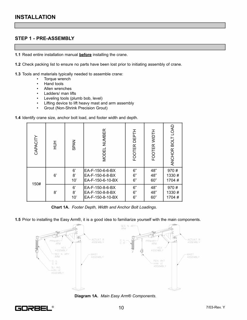
1.4 Identify crane size, anchor bolt load, and footer width and depth.
1.5 Prior to installing the Easy Arm®, it is a good idea to familiarize yourself with the main components.
INSTALLATION
STEP 1 - PRE-ASSEMBLYC
AP
AC
ITY
HU
H
SP
AN
MO
DE
LN
UM
BE
R
FO
OT
ER
DE
PT
H
FO
OT
ER
WID
TH
AN
CH
OR
BO
LT
LO
AD
150#
6’
6’
8’
10’
EA-F-150-6-6-BX
EA-F-150-6-8-BX
EA-F-150-6-10-BX
6”
6”
6”
48”
48”
60”
970 #
1330 #
1704 #
8’
6’
8’
10’
EA-F-150-8-6-BX
EA-F-150-8-8-BX
EA-F-150-8-10-BX
6”
6”
6”
48”
48”
60”
970 #
1330 #
1704 #
Chart 1A. Footer Depth, Width and Anchor Bolt Loadings.
Diagram 1A. Main Easy Arm® Components.
10 7/03-Rev. Y®
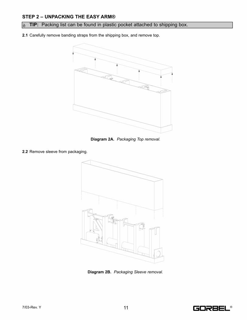
2.1 Carefully remove banding straps from the shipping box, and remove top.
2.2 Remove sleeve from packaging.
STEP 2 – UNPACKING THE EASY ARM®
TIP: Packing list can be found in plastic pocket attached to shipping box.
Diagram 2A. Packaging Top removal.
Diagram 2B. Packaging Sleeve removal.
117/03-Rev. Y
è
®
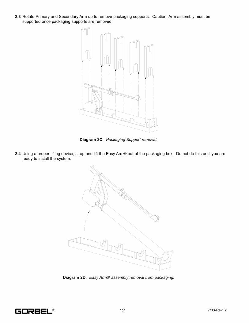
2.3 Rotate Primary and Secondary Arm up to remove packaging supports. Caution: Arm assembly must be
supported once packaging supports are removed.
2.4 Using a proper lifting device, strap and lift the Easy Arm® out of the packaging box. Do not do this until you are
ready to install the system.
Diagram 2C. Packaging Support removal.
Diagram 2D. Easy Arm® assembly removal from packaging.
12 7/03-Rev. Y®
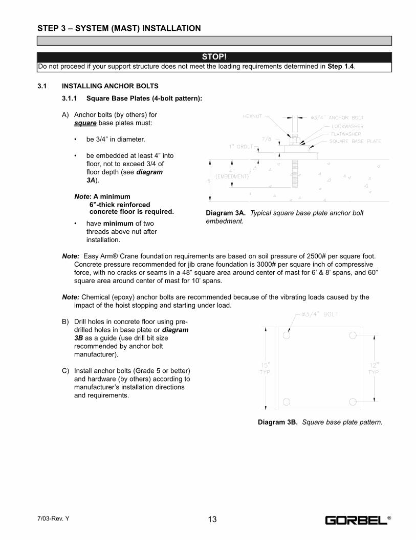
3.1 INSTALLING ANCHOR BOLTS
3.1.1 Square Base Plates (4-bolt pattern):
A) Anchor bolts (by others) for
square base plates must:
• be 3/4” in diameter.
• be embedded at least 4” into
floor, not to exceed 3/4 of
floor depth (see diagram3A).
Note: A minimum
6”-thick reinforcedconcrete floor is required.
• have minimum of two
threads above nut after
installation.
Note: Easy Arm® Crane foundation requirements are based on soil pressure of 2500# per square foot.
Concrete pressure recommended for jib crane foundation is 3000# per square inch of compressive
force, with no cracks or seams in a 48” square area around center of mast for 6’ & 8’ spans, and 60”
square area around center of mast for 10’ spans.
Note: Chemical (epoxy) anchor bolts are recommended because of the vibrating loads caused by the
impact of the hoist stopping and starting under load.
B) Drill holes in concrete floor using pre-
drilled holes in base plate or diagram3B as a guide (use drill bit size
recommended by anchor bolt
manufacturer).
C) Install anchor bolts (Grade 5 or better)
and hardware (by others) according to
manufacturer’s installation directions
and requirements.
STEP 3 – SYSTEM (MAST) INSTALLATION
STOP! Do not proceed if your support structure does not meet the loading requirements determined in Step 1.4.
Diagram 3A. Typical square base plate anchor boltembedment.
Diagram 3B. Square base plate pattern.
137/03-Rev. Y ®

3.2 INSTALLING AND PLUMBING MAST
A) Cover entire base-plate area with one inch of non-shrink precision grout. Set mast in place.
B) Mount a 9” Torpedo Level to the back surface of the Main Pivot Block (diagram 3C).
C) Pick a starting point and plumb the Main Pivot Shaft by adjusting the Mast at the base-plate. Rotate the
Head Assembly and plumb the Main Pivot Shaft every 60°.
D) Once the Main Pivot Pin is plumb and grout has cured, tighten bolts until base-plate is completely seated
in grout.
DO NOT
PLUMB THE
MAST PIPE
USING A
LEVEL.
WARNINGMast pin must be plumb to prevent arm assembly from drifting.
Diagram 3C. Plumbing the mast.
14 7/03-Rev. Y®
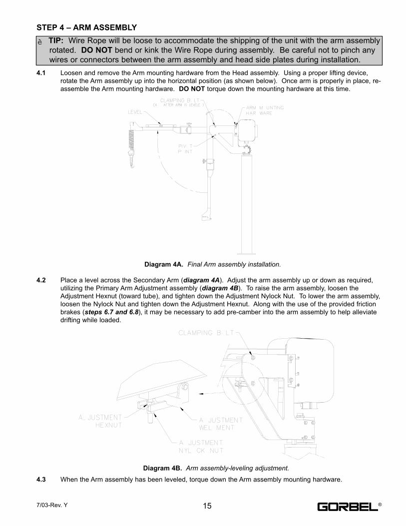
4.1 Loosen and remove the Arm mounting hardware from the Head assembly. Using a proper lifting device,
rotate the Arm assembly up into the horizontal position (as shown below). Once arm is properly in place, re-
assemble the Arm mounting hardware. DO NOT torque down the mounting hardware at this time.
4.2 Place a level across the Secondary Arm (diagram 4A). Adjust the arm assembly up or down as required,
utilizing the Primary Arm Adjustment assembly (diagram 4B). To raise the arm assembly, loosen the
Adjustment Hexnut (toward tube), and tighten down the Adjustment Nylock Nut. To lower the arm assembly,
loosen the Nylock Nut and tighten down the Adjustment Hexnut. Along with the use of the provided friction
brakes (steps 6.7 and 6.8), it may be necessary to add pre-camber into the arm assembly to help alleviate
drifting while loaded.
4.3 When the Arm assembly has been leveled, torque down the Arm assembly mounting hardware.
STEP 4 – ARM ASSEMBLY
TIP: Wire Rope will be loose to accommodate the shipping of the unit with the arm assembly
rotated. DO NOT bend or kink the Wire Rope during assembly. Be careful not to pinch any
wires or connectors between the arm assembly and head side plates during installation.
Diagram 4A. Final Arm assembly installation.
Diagram 4B. Arm assembly-leveling adjustment.
157/03-Rev. Y
è
®
STANDARD:
5.1 Prior to final wiring, inspect the entire system to assure that all connections are seated properly, and are
without kinks or bends. Verify the following connections:
a) Coil Cord to Handle
b) Coil Cord to Coil Cord Extension (located internal of the secondary arm tube)
c) Coil Cord Extension to Actuator Assembly
d) Slack Switch Connection at Slack Switch
e) Slack Switch Connection at Actuator assembly
f) Power to Actuator assembly
5.2 Connect a 220 VAC single-phase power source through a Disconnect Switch (by others) to the junction box
on the mast (Reference wiring Diagram #C5).
TRANSFORMER (OPTION):
110 VAC (Step Up - Standard)
5.3 System will be supplied standard with a Transformer mounted directly to the mast, and a 10’ long input
power cord pre-wired to the secondary side of the transformer. Connect a 110 VAC single-phase power
source through a Disconnect Switch (by others) to the power cord (Reference wiring Diagram #C6).
460 VAC (Step Down - Optional)
5.4 Customer must wire primary power directly to the Transformer. (Reference wiring diagram # C5)
6.1 Turn on the Disconnect Switch (by others) to apply power to the Easy Arm®.
6.2 Disengage the Emergency Stop (E-stop) button located on the front face of the handle.
6.3 The system will complete the “Power Up Diagnostic Test” described in the “Lift Interface Features” section of
this manual on page 7.
6.4 When the “Power Up Diagnostic Test” has been successfully completed the unit is ready for operation.
6.5 Standard Operation: Depress the operator present switch on the Sliding Handle, and run the unit up and
down several times (at least 20 times in each direction) to assure that there is no mechanical binding in the
lift system, or electrical connection issues. If Easy Arm® is equipped with the Pendant Handle, depress the
up and down levers to run the unit up and down. Take note of the speed of the unit as it is raised and
lowered. The maximum speed of the Easy Arm® can be adjusted using the 10 position Speed Selector
switch located at the Controls Interface back at the bottom face of the Actuator assembly. Using a small flat
head screwdriver, the position of the switch can be turned to any of the positions that are numbered from 0
to 9. If a slower maximum speed is desired, position the switch to a smaller number (towards 0). If a faster
maximum speed is desired, position the switch to a larger number (towards 9). The maximum standard
speed of the Easy Arm® is 150 fpm unloaded, and 125 fpm at 150#.
TIP: Do not connect to main power until all assembly is complete.
STEP 5 – ELECTRICAL POWER CONNECTION
TIP: Do not depress the operator present switch on the Sliding Handle during startup.
STEP 6 – INITIAL POWER-UP
16 7/03-Rev. Y
è
è
WARNINGSource power to the Easy Arm® unit is to measure 220 VAC (1 Phase) +/- 10%. Minimum voltage equals 198 VAC.
Maximum voltage must NOT exceed 242 VAC. Voltages greater than 242 VAC will result in premature Controls
failure.
®
6.6 Float Mode (if equipped): Lift up a load greater than 20 lbs. Settle the Load and depress the “Float Mode
Enabled” button. ***Do not hold onto the part while initiating Float Mode***. This will give the unit a false
reading and cause excessive drift. Grasping the load, run the unit up and down several times (at least 20
times in each direction), to assure proper operation. Float Mode should provide a nice smooth feel.
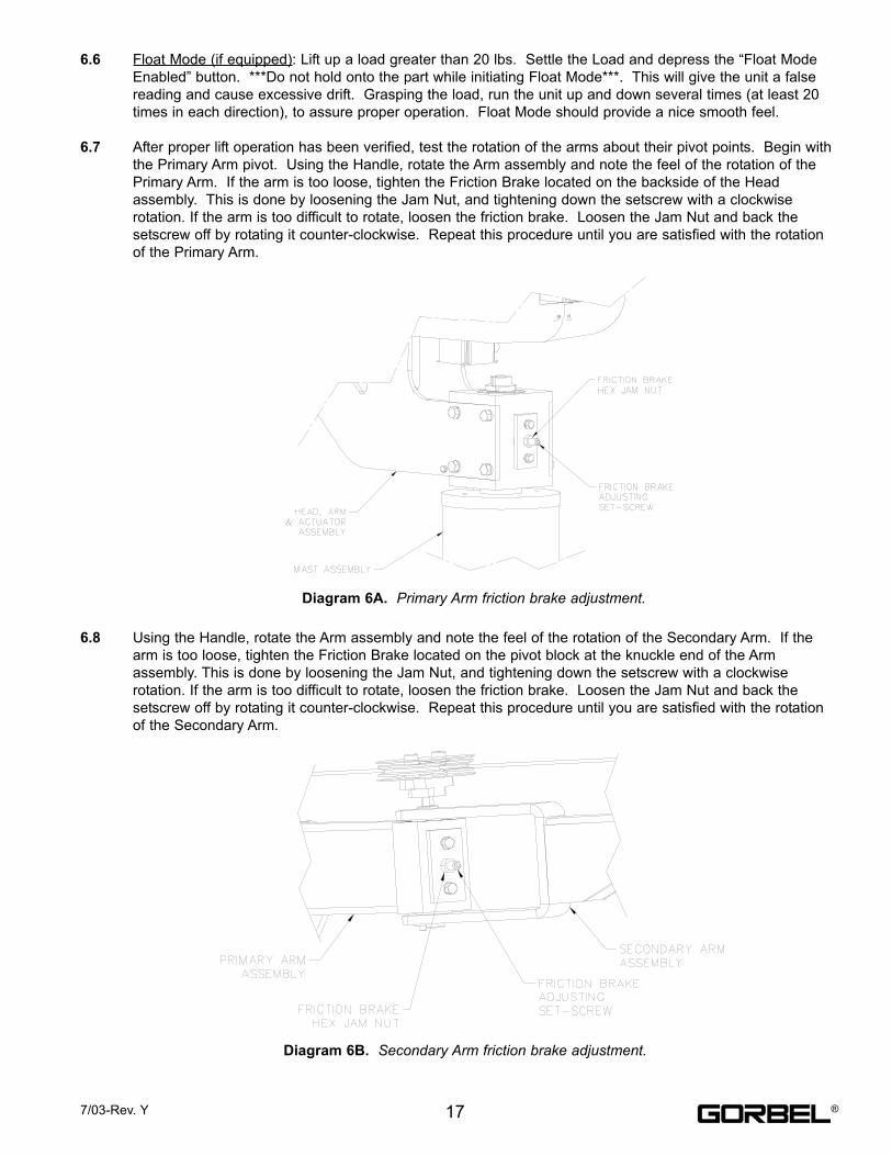
6.7 After proper lift operation has been verified, test the rotation of the arms about their pivot points. Begin with
the Primary Arm pivot. Using the Handle, rotate the Arm assembly and note the feel of the rotation of the
Primary Arm. If the arm is too loose, tighten the Friction Brake located on the backside of the Head
assembly. This is done by loosening the Jam Nut, and tightening down the setscrew with a clockwise
rotation. If the arm is too difficult to rotate, loosen the friction brake. Loosen the Jam Nut and back the
setscrew off by rotating it counter-clockwise. Repeat this procedure until you are satisfied with the rotation
of the Primary Arm.
6.8 Using the Handle, rotate the Arm assembly and note the feel of the rotation of the Secondary Arm. If the
arm is too loose, tighten the Friction Brake located on the pivot block at the knuckle end of the Arm
assembly. This is done by loosening the Jam Nut, and tightening down the setscrew with a clockwise
rotation. If the arm is too difficult to rotate, loosen the friction brake. Loosen the Jam Nut and back the
setscrew off by rotating it counter-clockwise. Repeat this procedure until you are satisfied with the rotation
of the Secondary Arm.
Diagram 6A. Primary Arm friction brake adjustment.
Diagram 6B. Secondary Arm friction brake adjustment.
177/03-Rev. Y ®
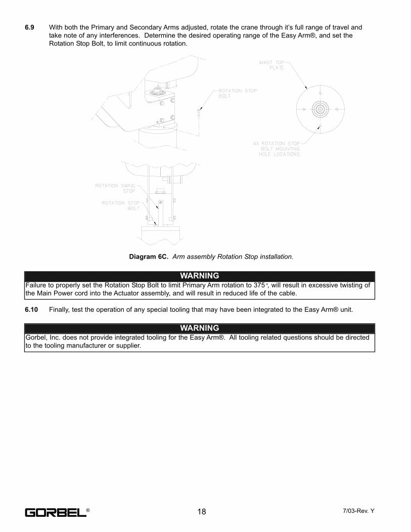
6.9 With both the Primary and Secondary Arms adjusted, rotate the crane through it’s full range of travel and
take note of any interferences. Determine the desired operating range of the Easy Arm®, and set the
Rotation Stop Bolt, to limit continuous rotation.
6.10 Finally, test the operation of any special tooling that may have been integrated to the Easy Arm® unit.
Diagram 6C. Arm assembly Rotation Stop installation.
WARNINGFailure to properly set the Rotation Stop Bolt to limit Primary Arm rotation to 375º, will result in excessive twisting of
the Main Power cord into the Actuator assembly, and will result in reduced life of the cable.
WARNINGGorbel, Inc. does not provide integrated tooling for the Easy Arm®. All tooling related questions should be directed
to the tooling manufacturer or supplier.
18 7/03-Rev. Y®
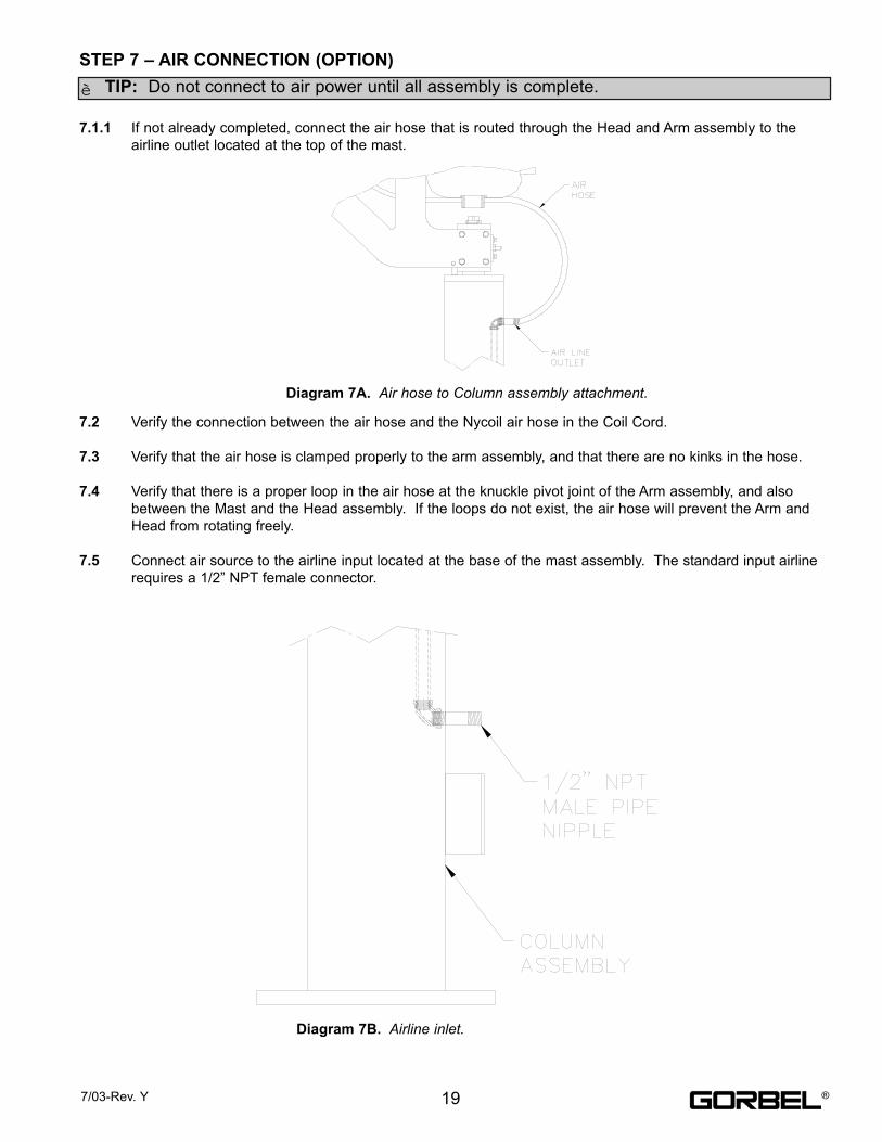
7.1.1 If not already completed, connect the air hose that is routed through the Head and Arm assembly to the
airline outlet located at the top of the mast.
7.2 Verify the connection between the air hose and the Nycoil air hose in the Coil Cord.
7.3 Verify that the air hose is clamped properly to the arm assembly, and that there are no kinks in the hose.
7.4 Verify that there is a proper loop in the air hose at the knuckle pivot joint of the Arm assembly, and also
between the Mast and the Head assembly. If the loops do not exist, the air hose will prevent the Arm and
Head from rotating freely.
7.5 Connect air source to the airline input located at the base of the mast assembly. The standard input airline
requires a 1/2” NPT female connector.
TIP: Do not connect to air power until all assembly is complete.
STEP 7 – AIR CONNECTION (OPTION)
Diagram 7A. Air hose to Column assembly attachment.
Diagram 7B. Airline inlet.
197/03-Rev. Y
è
®
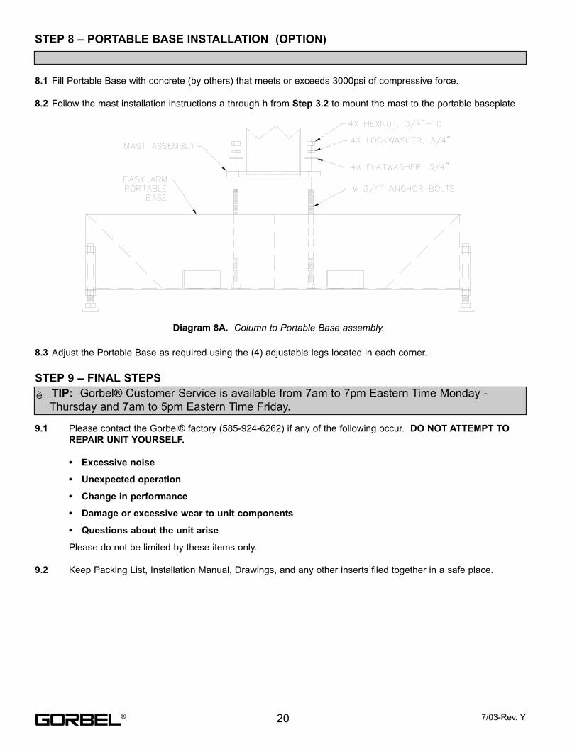
8.1 Fill Portable Base with concrete (by others) that meets or exceeds 3000psi of compressive force.
8.2 Follow the mast installation instructions a through h from Step 3.2 to mount the mast to the portable baseplate.
8.3 Adjust the Portable Base as required using the (4) adjustable legs located in each corner.
9.1 Please contact the Gorbel® factory (585-924-6262) if any of the following occur. DO NOT ATTEMPT TO
REPAIR UNIT YOURSELF.
• Excessive noise
• Unexpected operation
• Change in performance
• Damage or excessive wear to unit components
• Questions about the unit arise
Please do not be limited by these items only.
9.2 Keep Packing List, Installation Manual, Drawings, and any other inserts filed together in a safe place.
STEP 8 – PORTABLE BASE INSTALLATION (OPTION)
Diagram 8A. Column to Portable Base assembly.
TIP: Gorbel® Customer Service is available from 7am to 7pm Eastern Time Monday -
Thursday and 7am to 5pm Eastern Time Friday.
STEP 9 – FINAL STEPS
20 7/03-Rev. Y
è
®
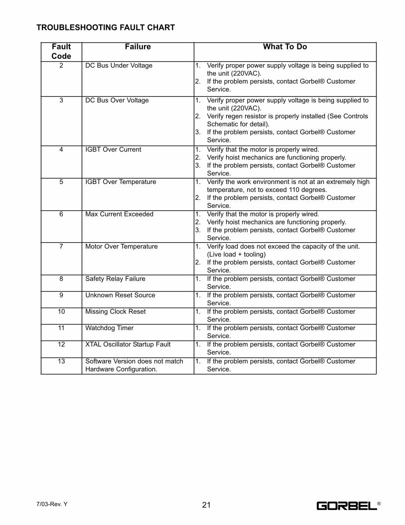
TROUBLESHOOTING FAULT CHART
Fault
Code
Failure What To Do
2 DC Bus Under Voltage 1. Verify proper power supply voltage is being supplied to
the unit (220VAC).
2. If the problem persists, contact Gorbel® Customer
Service.
3 DC Bus Over Voltage 1. Verify proper power supply voltage is being supplied to
the unit (220VAC).
2. Verify regen resistor is properly installed (See Controls
Schematic for detail).
3. If the problem persists, contact Gorbel® Customer
Service.
4 IGBT Over Current 1. Verify that the motor is properly wired.
2. Verify hoist mechanics are functioning properly.
3. If the problem persists, contact Gorbel® Customer
Service.
5 IGBT Over Temperature 1. Verify the work environment is not at an extremely high
temperature, not to exceed 110 degrees.
2. If the problem persists, contact Gorbel® Customer
Service.
6 Max Current Exceeded 1. Verify that the motor is properly wired.
2. Verify hoist mechanics are functioning properly.
3. If the problem persists, contact Gorbel® Customer
Service.
7 Motor Over Temperature 1. Verify load does not exceed the capacity of the unit.
(Live load + tooling)
2. If the problem persists, contact Gorbel® Customer
Service.
8 Safety Relay Failure 1. If the problem persists, contact Gorbel® Customer
Service.
9 Unknown Reset Source 1. If the problem persists, contact Gorbel® Customer
Service.
10 Missing Clock Reset 1. If the problem persists, contact Gorbel® Customer
Service.
11 Watchdog Timer 1. If the problem persists, contact Gorbel® Customer
Service.
12 XTAL Oscillator Startup Fault 1. If the problem persists, contact Gorbel® Customer
Service.
13 Software Version does not match
Hardware Configuration.
1. If the problem persists, contact Gorbel® Customer
Service.
217/03-Rev. Y ®
1. Rope Inspection
(A) Frequent Inspection
The operator or other designated person should visually inspect all ropes at the start of each shift. These visual
observations should be concerned with discovering gross damage, such as listed below, which may be an
immediate hazard:
(a) distortion of the rope such as kinking, crushing, unstranding, birdcaging, main strand displacement, or
core protrusion;
(b) general corrosion;
(c) broken or cut strands;
(d) number, distribution, and type of visible broken wires. [See next section on rope replacement]
When such damage is discovered, the rope shall either be removed from service or given an inspection as
detailed in the next section.
(B) Periodic Inspection
The inspection frequency shall be determined by a qualified person and shall be based on such factors as
expected rope life as determined by experience on the particular installation or similar installations; severity of
environment; percentage of capacity lifts; frequency rates of operation; and exposure to shock loads.
Inspections need not be at equal calendar intervals and should be more frequent as the rope approaches the
end of its useful life.
A designated person shall perform periodic inspections. This inspection shall cover the entire length of rope.
The individual outer wires in the strands of the rope shall be visible to this person during the inspection. Any
deterioration resulting in appreciable loss of original strength, such as described below, shall be noted, and
determination shall be made as to whether further use of the rope would constitute a hazard:
(a) points listed in previous section on frequent inspection;
(b) reduction of rope diameter below nominal diameter due to loss of core support, internal or external
corrosion, or wear of outside wires;
(c) severely corroded or broken wires at end connections;
(d) severely corroded, cracked, bent, worn, or improperly applied end connections.
Special care should be taken when inspecting sections of rapid deterioration, such as the following:
(a) sections in contact with saddles, equalizer sheaves, or other sheaves where rope travel is limited;
(b) sections of rope at or near terminal ends where corroded or broken wires may protrude;
(c) sections subject to reverse bends;
(d) sections of ropes that are normally hidden during visual inspection, such as parts passing over sheaves.
2. Rope Maintenance
Rope should be stored to prevent damage or deterioration.
Rope shall be unreeled or uncoiled in a manner to avoid kinking of or inducing a twist in the rope.
Before cutting rope, means shall be used to prevent unlaying of the strands.
During installation, care should be observed to avoid dragging of the rope in dirt or around objects that will
scrape, nick, crush, or induce sharp bends.
WIRE ROPE INSPECTION, MAINTENANCE & REPLACEMENT
22 7/03-Rev. Y®
Rope should be maintained in a well-lubricated condition. Gorbel recommends using Chain and Cable
Penetrating oil for lubrication. Lubricant applied as part of a maintenance program shall be compatible with the
original lubricant. Lubricant applied shall be of the type that does not hinder visual inspection. Immediately after
inspection, lubricant shall be applied before rope is returned to service. Those sections of rope that are located
over sheaves or otherwise hidden during inspection and maintenance procedures require special attention when
lubricating rope. The object of rope lubrication is to reduce internal friction and to prevent corrosion.
3. Rope Replacement Criteria
No precise rules can be given for determination of the exact time for rope replacement, since many factors are
involved. Once a rope reaches any one of the specified removal criteria, it may be allowed to operate to the end
of the work shift, based on the judgement of a qualified person. The rope shall be replaced after that work shift,
at the end of the day, or at the latest time prior to the equipment being used by the next work shift.
Removal criteria for the rope replacement shall be as follows:
(a) in running ropes, 12 randomly distributed broken wires in one lay or four broken wires in one strand in
one lay (See below);
(b) one outer wire broken at the contact point with the core of the rope, which has worked its way out of the
rope structure and protrudes or loops out from the rope structure;
(c) wear of one-third the original diameter of outside individual wires;
(d) kinking, crushing, birdcaging, or any other damage resulting in distortion of the rope structure;
(e) evidence of heat damage from any cause;
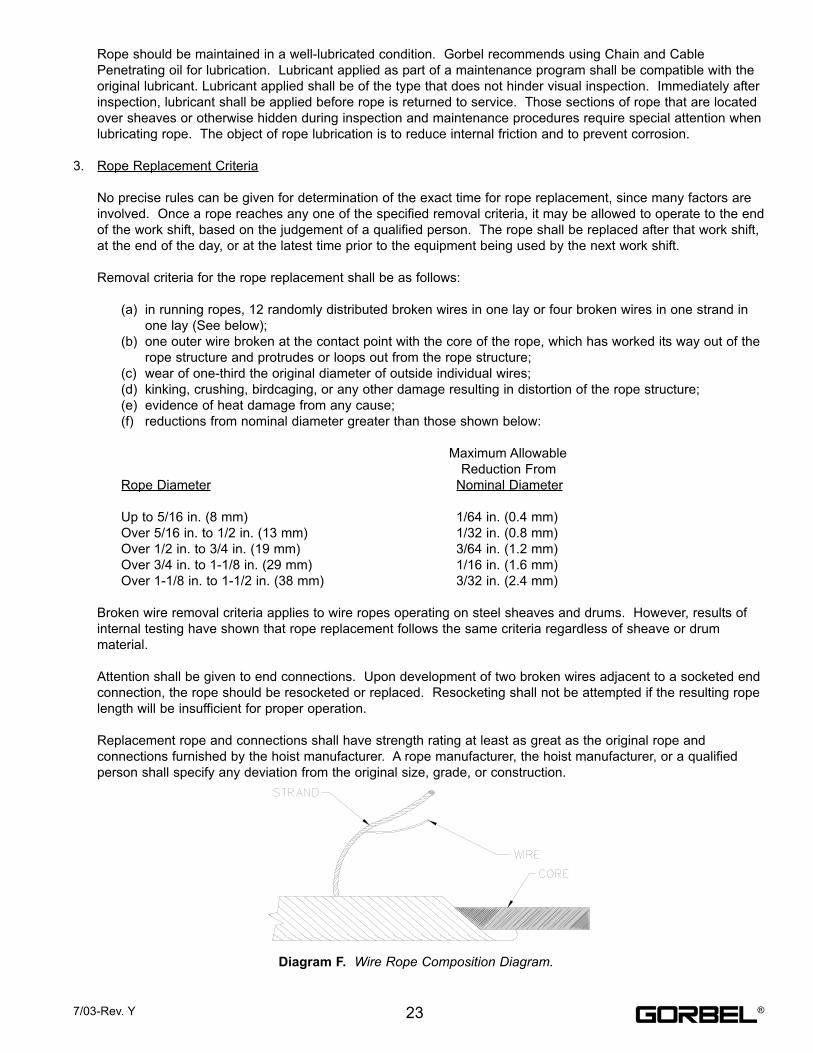
(f) reductions from nominal diameter greater than those shown below:
Maximum Allowable
Reduction From
Rope Diameter Nominal Diameter
Up to 5/16 in. (8 mm) 1/64 in. (0.4 mm)
Over 5/16 in. to 1/2 in. (13 mm) 1/32 in. (0.8 mm)
Over 1/2 in. to 3/4 in. (19 mm) 3/64 in. (1.2 mm)
Over 3/4 in. to 1-1/8 in. (29 mm) 1/16 in. (1.6 mm)
Over 1-1/8 in. to 1-1/2 in. (38 mm) 3/32 in. (2.4 mm)
Broken wire removal criteria applies to wire ropes operating on steel sheaves and drums. However, results of
internal testing have shown that rope replacement follows the same criteria regardless of sheave or drum
material.
Attention shall be given to end connections. Upon development of two broken wires adjacent to a socketed end
connection, the rope should be resocketed or replaced. Resocketing shall not be attempted if the resulting rope
length will be insufficient for proper operation.
Replacement rope and connections shall have strength rating at least as great as the original rope and
connections furnished by the hoist manufacturer. A rope manufacturer, the hoist manufacturer, or a qualified
person shall specify any deviation from the original size, grade, or construction.
237/03-Rev. Y
Diagram F. Wire Rope Composition Diagram.
®

4. Wire Rope Replacement Procedure (to be performed by qualified maintenance personnel only):
a) Depress the Emergency Stop (E-Stop) button on the Handle.
b) Remove the Covers from the Actuator assembly. (Reference Figure # B17)
1) Remove the Motor side Cover (Item # 3) from the Actuator assembly first. To remove this Cover
you must first loosen, but do not remove item # 5 (6x). Remove item # 8 (1x) on Motor side
cover only. Slide Cover off of the Actuator assembly utilizing the slotted openings in the Cover.
2) Remove the Controls side Cover (Item # 2) from the Actuator assembly. To remove this Cover
you must first unscrew and remove the Coil Cord Extension Plug from the Controls Interface.
Now, loosen the locking nut from the Cord Grip (Item # 9) assembled at the bottom of the
Controls side Cover. Slide Cover off of the Actuator assembly utilizing the slotted openings in
the Cover.
c) Re-attach the Coil Cord Extension Plug to the Controls Interface.
d) Remove the Nylon Drum Cover from the Actuator. (Reference Figure #B16) Remove the mounting
bolts and lockwashers, and slide the Drum Cover off of the Main Drum Pulley.
e) Remove the Upper/Lower Limit Switch assembly from the Actuator. (Reference Figure # B15) Remove
the mounting hexnut and lockwasher, and remove the assembly from the Actuator. **DO NOT detach
the wiring from the Upper and Lower Limit switches**
f) Release the Emergency Stop (E-Stop) button on the Handle. At the Controls Interface, jog the unit
down until the remaining Wire Rope has been payed off of the Main Drum Pulley.
g) Depress the Emergency Stop (E-Stop) button on the Handle.
h) Set the Handle down on a secure base while Wire Rope replacement is taking place. It is not
necessary to disassemble the Handle or Coil Cord from the Secondary Arm.
i) Detach the Wire Rope from the Sliding Handle (if equipped). (Reference Figure # A5) Remove the
cotter and clevis pins from the Handle Swivel assembly. Pull the damaged Wire Rope out of the Swivel
assembly.
j) Verify that the Handle has been set down on a secure base, and that there is no weight on the Wire
Rope assembly.
k) Remove the Wire Rope termination cover from the Main Drum Pulley. (Reference Figure # B12)
Remove hardware items 6 & 7 from the Main Drum Pulley, and remove the Wire Rope Cover (item #4).
l) Remove the terminated end of the Wire Rope from the Main Drum Pulley. Do so by simply lifting the
terminated end out of the groove in the Drum Pulley.
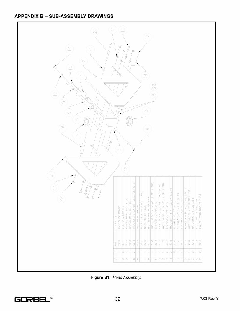
m) Remove the Wire Rope from the Arm Assembly Pivot joint. (Reference Figure #’s B8 & D2) Remove
the mounting Shoulder Bolts (item # 9), Support Plate (Item #5, Top only), Pulley Spacers (Item # 6, Top
(2) only), and Idler Pulley assemblies from the Pivot assembly. Remove the damaged Wire Rope. Do
not reassemble the Pivot at this time.
n) Remove the Wire Rope from the Slack Pulley assembly at the end of the Secondary Arm. (ReferenceFigure #’s B5, B6 & B7) Remove the E-Style Retaining Rings from the Slack assembly shaft, and
slide the shafts out of the pulley assembly. Remove the Shoulder bolts from the Secondary Arm
weldment, releasing the Springs from the weldment. Leave the Springs attached to the Slack Pulley
assembly. Lift the Slack Pulley assembly out through the top of the Secondary Arm weldment. Remove
the (3) mounting bolts that assemble the Pulley Housing and Pulley Housing Cover together. Separate
the Housing and remove the damaged Wire Rope from the pulley.
o) Discard the damaged Wire Rope.
24 7/03-Rev. Y®

p) Begin re-assembly with the new replacement Wire Rope.
q) Route the new Wire Rope through, and re-assemble the Slack Pulley assembly. (Reference Figure #’sB5, B6 & B7) Assemble the Pulley Housing and Pulley Housing Cover around the Slack Pulley, being
sure to capture the Wire Rope on the pulley in it’s proper orientation. Drop the Slack Pulley assembly
down into the Secondary Arm weldment, and re-assemble the Shoulder Bolts into the weldment sides,
being sure to capture the free end of the (2) extension Springs. Line up the Slack Pulley assembly with
the shaft hole openings in the sides of the weldment, and insert the shafts. Reassemble the E-Style
Retaining Rings to the shafts. Push down and release the top of the Slack Pulley assembly to verify
that it is operating correctly. When pushed down to its lower limit, the Slack Switch should be
compressed and activated. When released, the Slack Pulley assembly should repeatedly raise off of the
Slack Switch.
r) Route the new Wire Rope through and re-assemble the Arm Pivot assembly. (Reference Figure #’s B8& D2) Capture the Wire Rope between the (2) Idler Pulleys (Item # 7), assuring proper orientation of
both the Pulleys and Wire Rope. Lower Pulleys onto the (2) lower Pulley Spacers (Item # 6), locate the
(2) upper Pulley Spacers (Item # 6), and the top Support Plate (Item # 5). Assemble the (2) Shoulder
Bolts, and clamp the assembly together.
s) Pull the Wire Rope through to the Main Drum Pulley in the Actuator. (Reference Figure # B12)
Assemble the terminated end of the Wire Rope into the termination groove and opening in the topside of
the Drum Pulley. Re-assemble the Wire Rope Termination Cover (Item # 4), using the hardware
provided (Items 6 & 7).
t) Release the Emergency Stop (E-Stop) button on the Handle. At the Controls, jog the unit up until the
Handle end of the Wire Rope is about 4 feet off of the floor.
u) Depress the Emergency Stop (E-Stop) button on the Handle.
v) Re-attach the Sliding Handle (if equipped) to the Wire Rope using the Clevis and Cotter Pin.
(Reference Figure # A5)
w) Re-assemble the Upper/Lower Limit Switch assembly to the Actuator. (Reference Figure #B15) Be
sure to capture the lip of the Nylon Limit Switch block in the same groove as the Wire Rope that is
exiting the Main Drum Pulley.
x) Re-assemble the Drum Cover to the Actuator. (Reference Figure # B16)
y) Release the Emergency Stop (E-Stop) button on the Handle.
z) Grasp the Operator Present Switch Lever and run the Sliding Handle (if equipped, or use Pendant
Handle) up and down several times (at least 20 times in each direction). Assure proper operation of the
lifting device.
aa) Depress the Emergency Stop (E-Stop) button on the Handle.
bb) Unscrew and remove the Coil Cord Extension Plug from the Controls Interface.
cc) Re-assemble the Controls side Cover (Item # 2) to the Actuator assembly. (Reference Figure # B17).
Re-assemble the Power Cord Grip (Item # 9) to the slot opening in the bottom of the Cover. Slide the
Cover onto the Actuator using the slotted openings to capture the hardware. Tighten down the
mounting hardware.
dd) Re-assemble the Motor side Cover (Item # 3) to the Actuator assembly. (Reference Figure # B17)
Slide the Cover onto the Actuator using the slotted openings to capture the hardware. Tighten down the
mounting hardware. Re-assemble mounting screw (Item # 8) between the Motor side Cover and the
Controls side Cover.
ee) Release the Emergency Stop (E-Stop) button on the Handle, and the unit is ready to proceed with
normal operation.
257/03-Rev. Y ®
UPPER AND LOWER LIMIT SWITCH ADJUSTING PROCEDURE
1) Run the Handle to the mid-point of travel.
2) Depress the Emergency Stop (E-Stop) button on the Handle.
3) Remove the Covers from the Actuator assembly. (Reference Figure # B17)
a) Remove the Motor side Cover (Item # 3) from the Actuator assembly first. To remove this Cover
you must first loosen, but do not remove Item # 5 (6x). Remove item # 8 (1x) on Motor side
cover only. Slide Cover off of the Actuator assembly utilizing the slotted openings in the Cover.
b) Remove the Controls side Cover (Item # 2) from the Actuator assembly. To remove this Cover
you must first unscrew and remove the Coil Cord Extension Plug from the Controls Interface.
Now, loosen the locking nut from the Cord Grip (Item # 9) assembled at the bottom of the
Controls side Cover. Slide Cover off of the Actuator assembly utilizing the slotted openings in
the Cover.
4) Re-attach the Coil Cord Extension Plug to the Controls Interface.
5) Remove the Nylon Drum Cover from the Actuator. (Reference Figure #B16) Remove the mounting bolts and
lockwashers, and slide the Drum Cover off of the Main Drum Pulley.
6) Remove the Upper/Lower Limit Switch assembly from the Actuator. (Reference Figure # B15) Remove the
mounting hexnut and lockwasher, and remove the assembly from the Actuator. Detach the wiring from the
Upper and Lower Limit switches.
7) Remove the mounting Bolts, Spacer Shafts, and Nylon Limit Switch block from the assembly. (ReferenceFigure # B14) Remove the Limit Switch(es) mounting Hexnut and Lockwasher from the back side of the Switch
Bracket. (Reference Figure # B13) Remove the Limit Switch(es) and mounting bolts. Re-locate the Switch(es)
to the proper pre-drilled set of holes. Re-assemble the mounting bolt and hexnuts for the switch(es). Reattach
the wiring to the switches.
8) Re-assemble the Nylon Limit Switch Block, Spacer Shafts, and mounting Bolts. (Reference Figure # B14)
Re-assemble the Upper/Lower Limit Switch assembly to the Actuator. (Reference Figure # B15) Be sure to
capture the lip of the Nylon Limit Switch block in the same groove as the Wire Rope that is exiting the Main
Drum Pulley.
9) Release the Emergency Stop (E-Stop) button on the Handle.
10) Grasp the Operator Present Switch Lever and run the Sliding Handle (if equipped, or use Pendant Handle) up
and down several times (at least 20 times in each direction). Verify that the adjusted limits are correct. If yes,
continue to step 10. If no, return to step 5.
11) Depress the Emergency Stop (E-Stop) button on the Handle.
12) Unscrew and remove the Coil Cord Extension Plug from the Controls Interface.
13) Re-assemble the Nylon Drum Cover to the Actuator. (Reference Figure #B16)
14) Re-assemble the Controls side Cover (Item # 2) to the Actuator assembly. (Reference Figure # B17).
Reassemble the Power Cord Grip (Item # 9) to the slot opening in the bottom of the Cover. Slide the Cover onto
the Actuator using the slotted openings to capture the hardware. Tighten down the mounting hardware.
15) Re-assemble the Motor side Cover (Item # 3) to the Actuator assembly. (Reference Figure # B17) Slide the
Cover onto the Actuator using the slotted openings to capture the hardware. Tighten down the mounting
hardware. Re-assemble mounting screw (Item # 8) between the Motor side Cover and the Controls side Cover.
16) Release the Emergency Stop (E-Stop) button on the Handle, and the unit is ready to proceed with normal
operation.
26 7/03-Rev. Y®
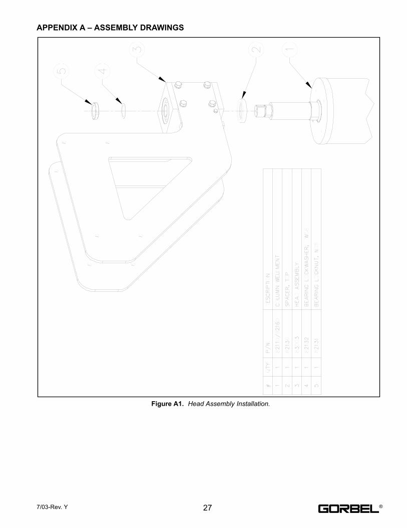
APPENDIX A – ASSEMBLY DRAWINGS
Figure A1. Head Assembly Installation.
277/03-Rev. Y ®
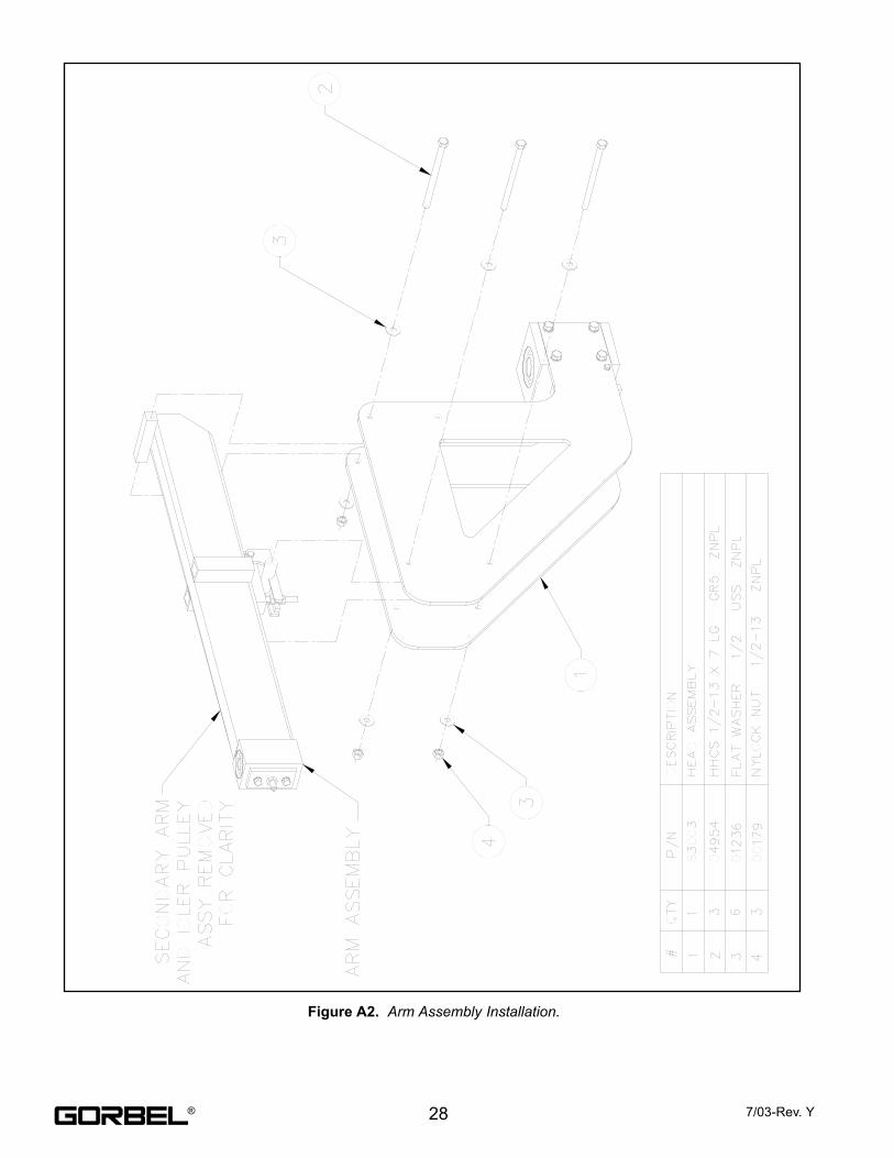
Figure A2. Arm Assembly Installation.
28 7/03-Rev. Y®
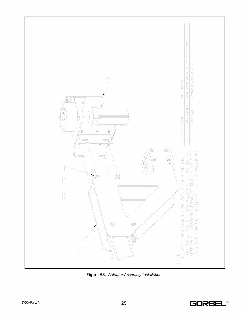
Figure A3. Actuator Assembly Installation.
297/03-Rev. Y ®
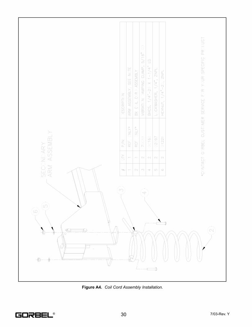
Figure A4. Coil Cord Assembly Installation.
30 7/03-Rev. Y®
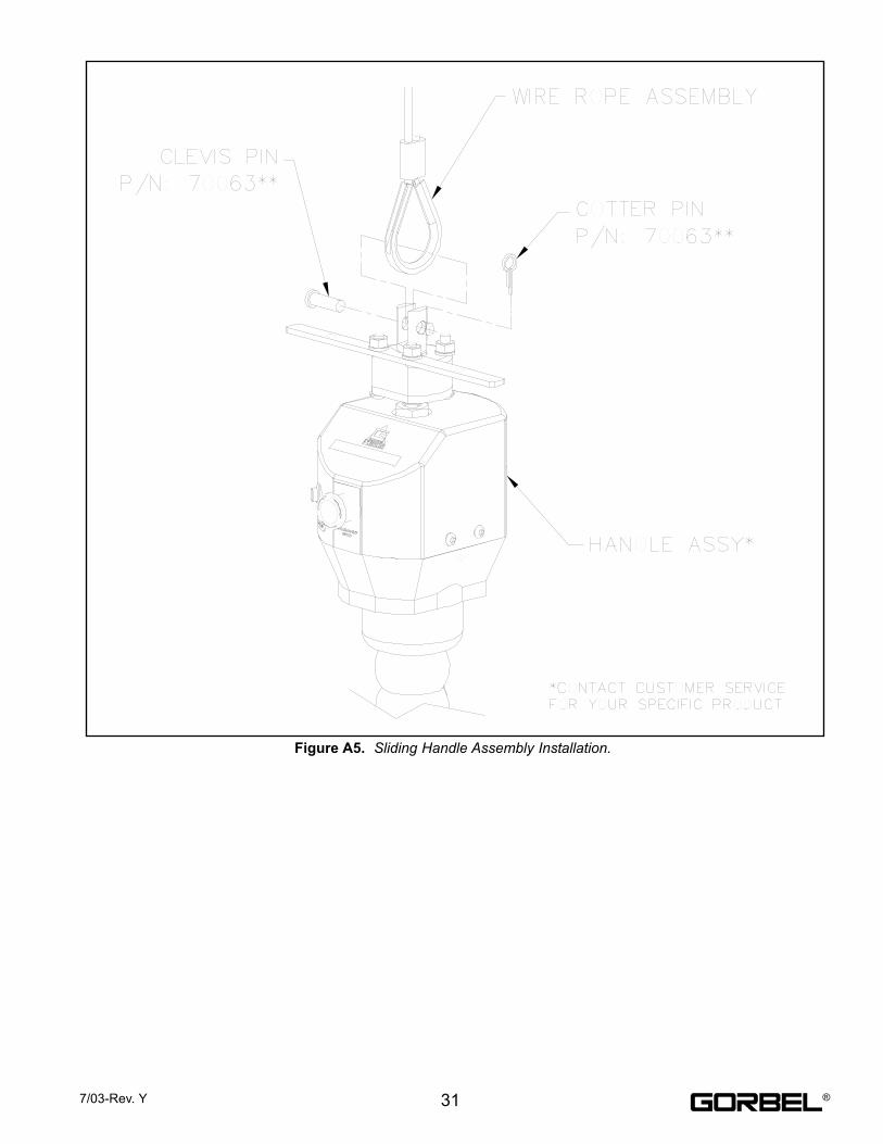
Figure A5. Sliding Handle Assembly Installation.
317/03-Rev. Y ®
APPENDIX B – SUB-ASSEMBLY DRAWINGS
Figure B1. Head Assembly.
32 7/03-Rev. Y®
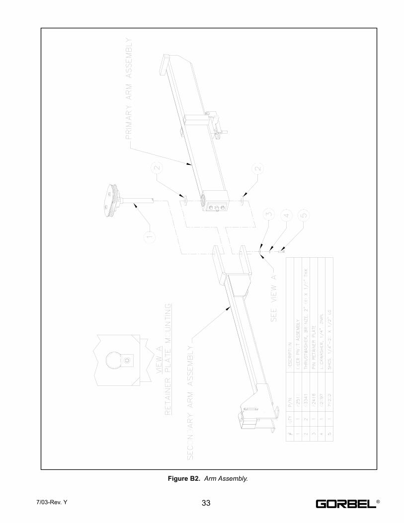
Figure B2. Arm Assembly.
337/03-Rev. Y ®
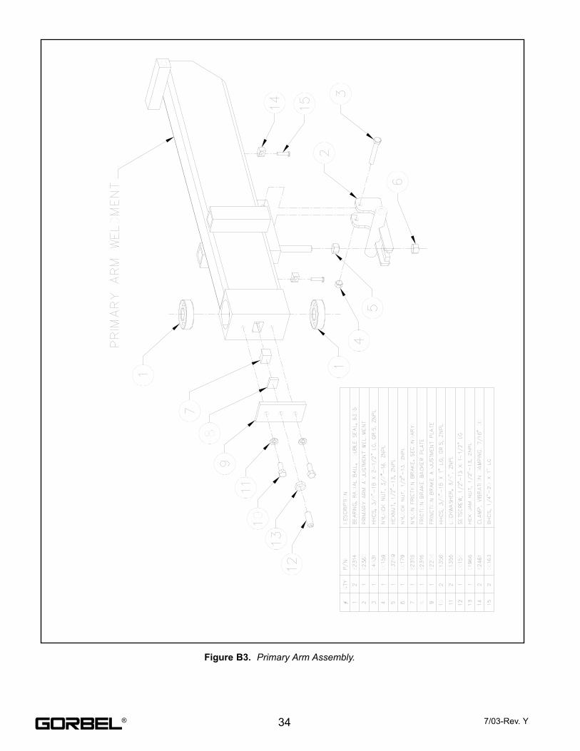
Figure B3. Primary Arm Assembly.
34 7/03-Rev. Y®
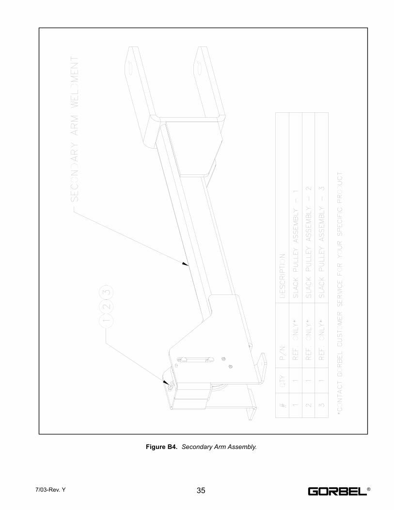
Figure B4. Secondary Arm Assembly.
357/03-Rev. Y ®
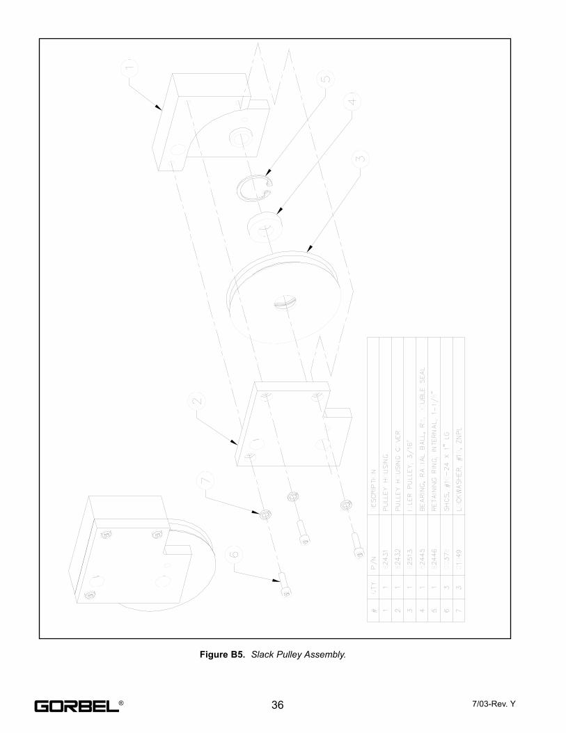
Figure B5. Slack Pulley Assembly.
36 7/03-Rev. Y®
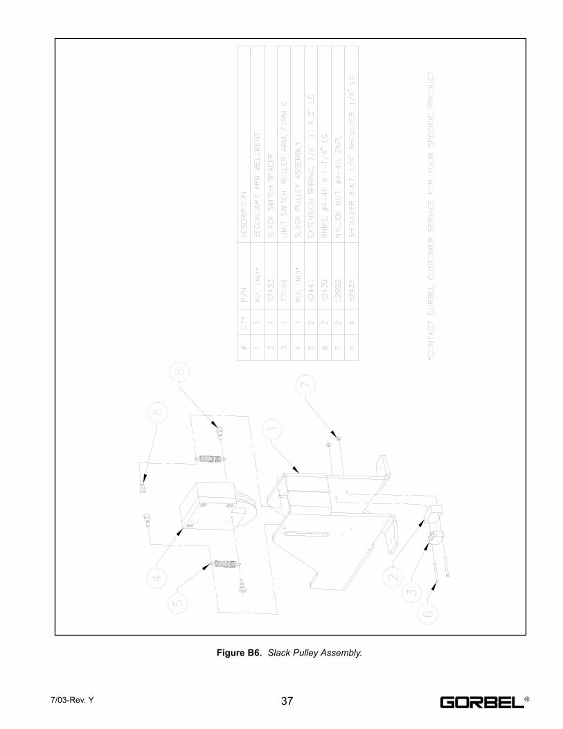
Figure B6. Slack Pulley Assembly.
377/03-Rev. Y ®
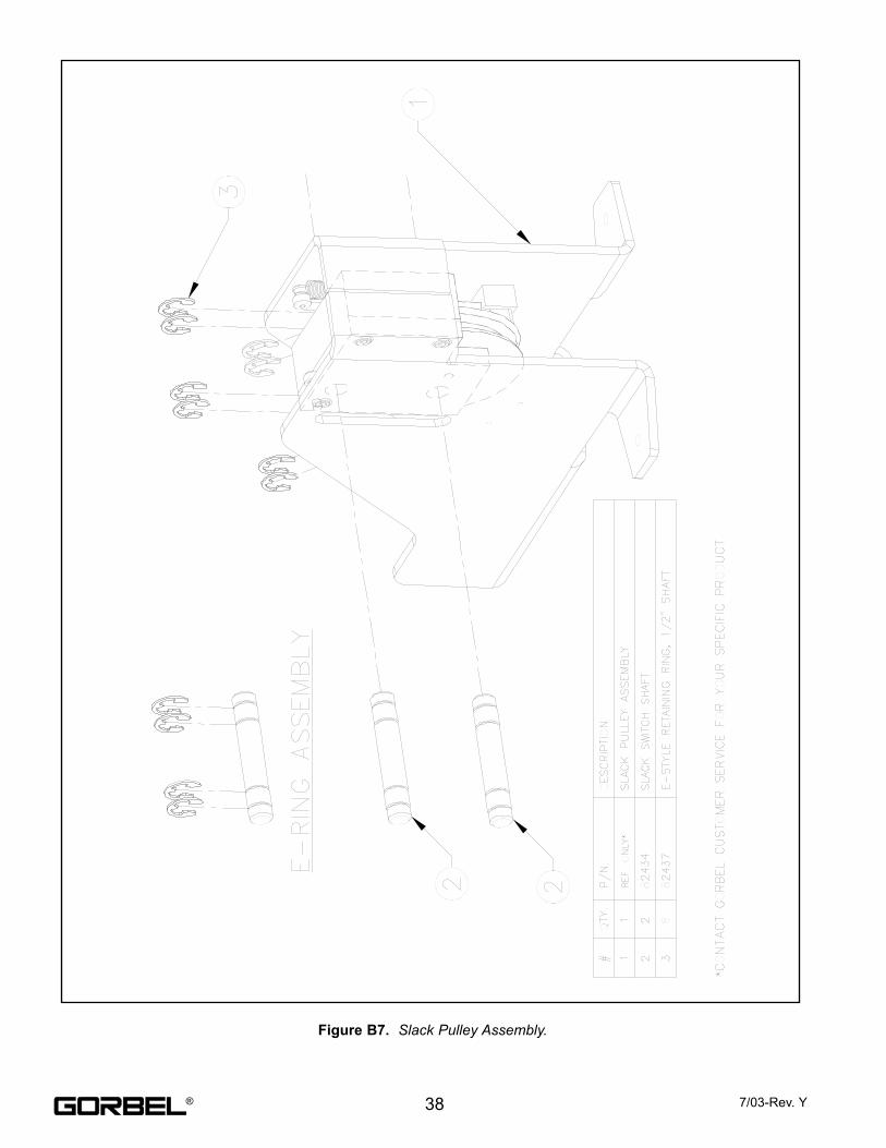
Figure B7. Slack Pulley Assembly.
38 7/03-Rev. Y®

Figure B8. Idler Pivot Assembly.
397/03-Rev. Y ®
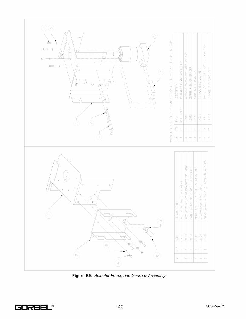
Figure B9. Actuator Frame and Gearbox Assembly.
40 7/03-Rev. Y®
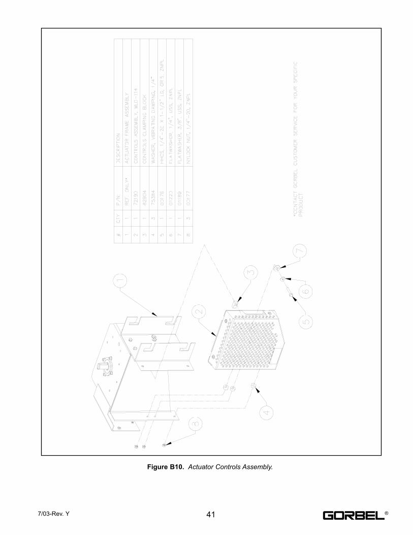
Figure B10. Actuator Controls Assembly.
417/03-Rev. Y ®
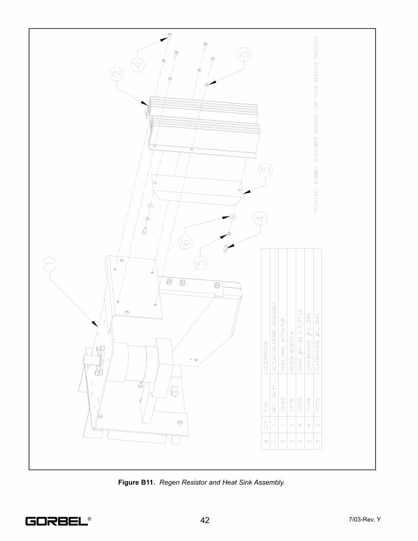
Figure B11. Regen Resistor and Heat Sink Assembly.
42 7/03-Rev. Y®
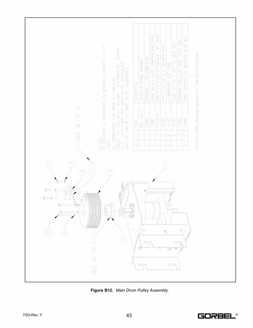
Figure B12. Main Drum Pulley Assembly.
437/03-Rev. Y ®
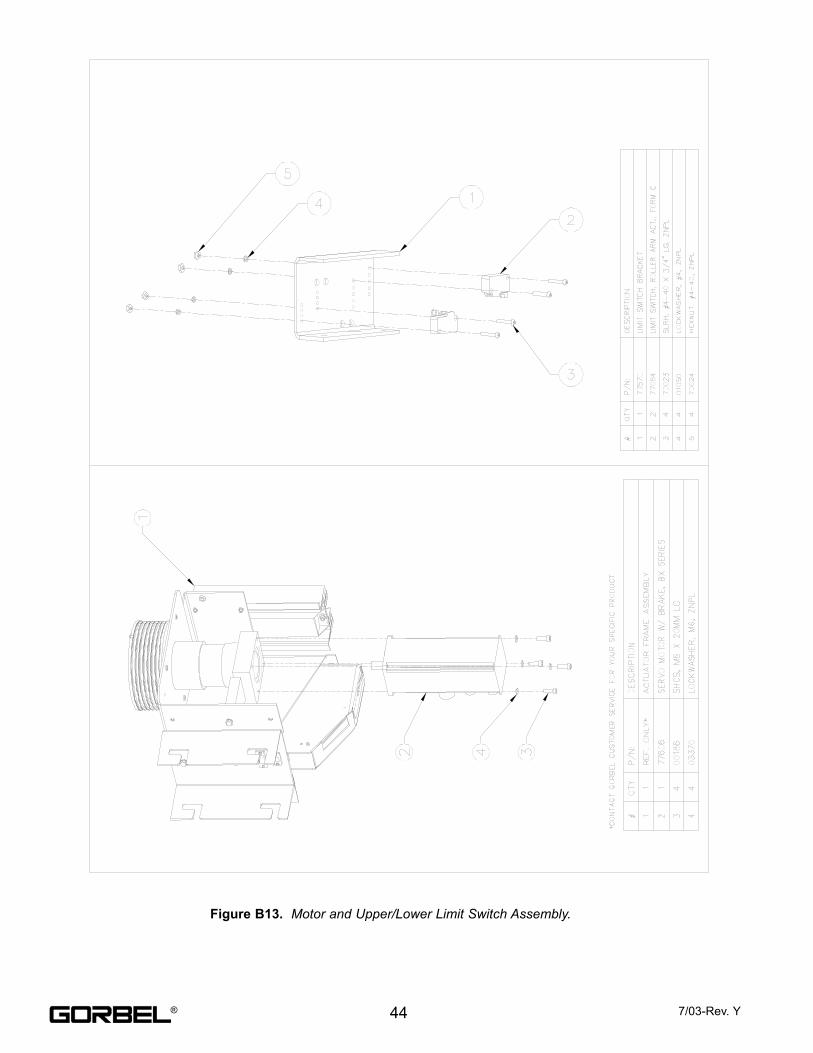
Figure B13. Motor and Upper/Lower Limit Switch Assembly.
44 7/03-Rev. Y®
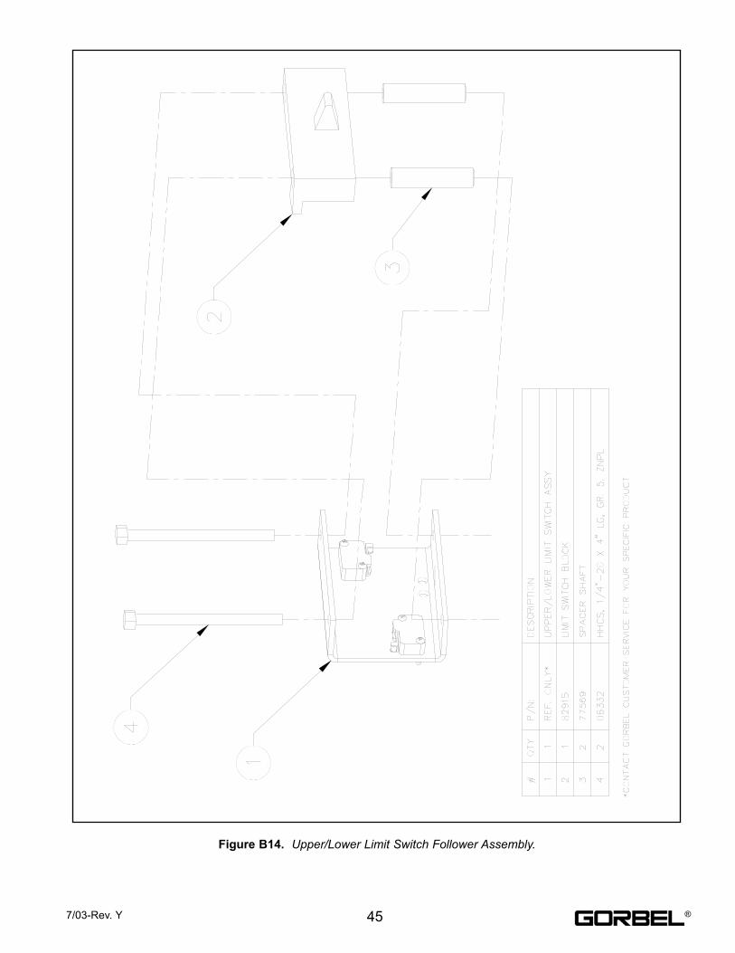
Figure B14. Upper/Lower Limit Switch Follower Assembly.
457/03-Rev. Y ®
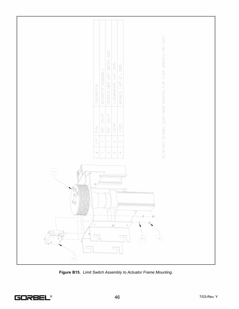
Figure B15. Limit Switch Assembly to Actuator Frame Mounting.
46 7/03-Rev. Y®
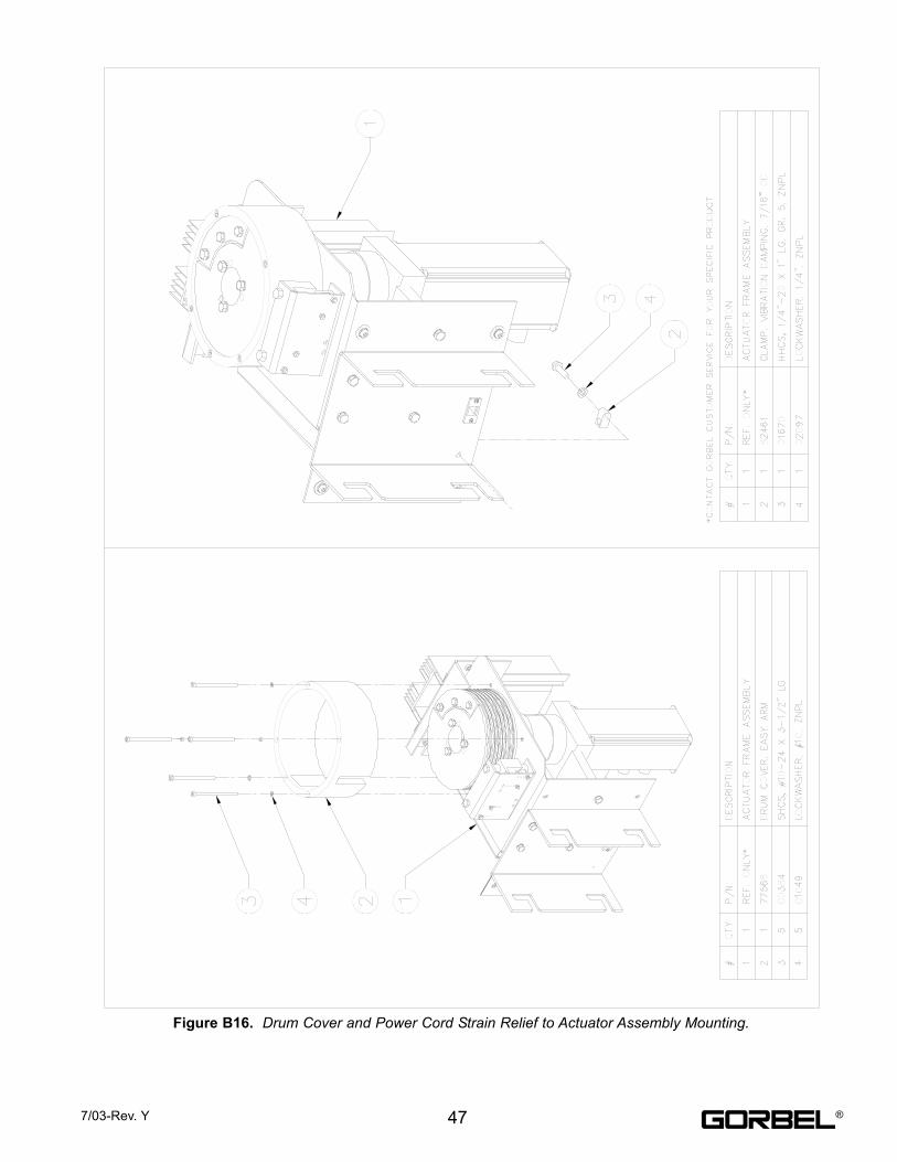
Figure B16. Drum Cover and Power Cord Strain Relief to Actuator Assembly Mounting.
477/03-Rev. Y ®
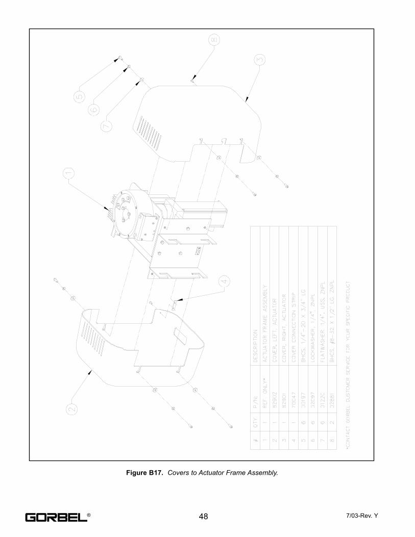
Figure B17. Covers to Actuator Frame Assembly.
48 7/03-Rev. Y®
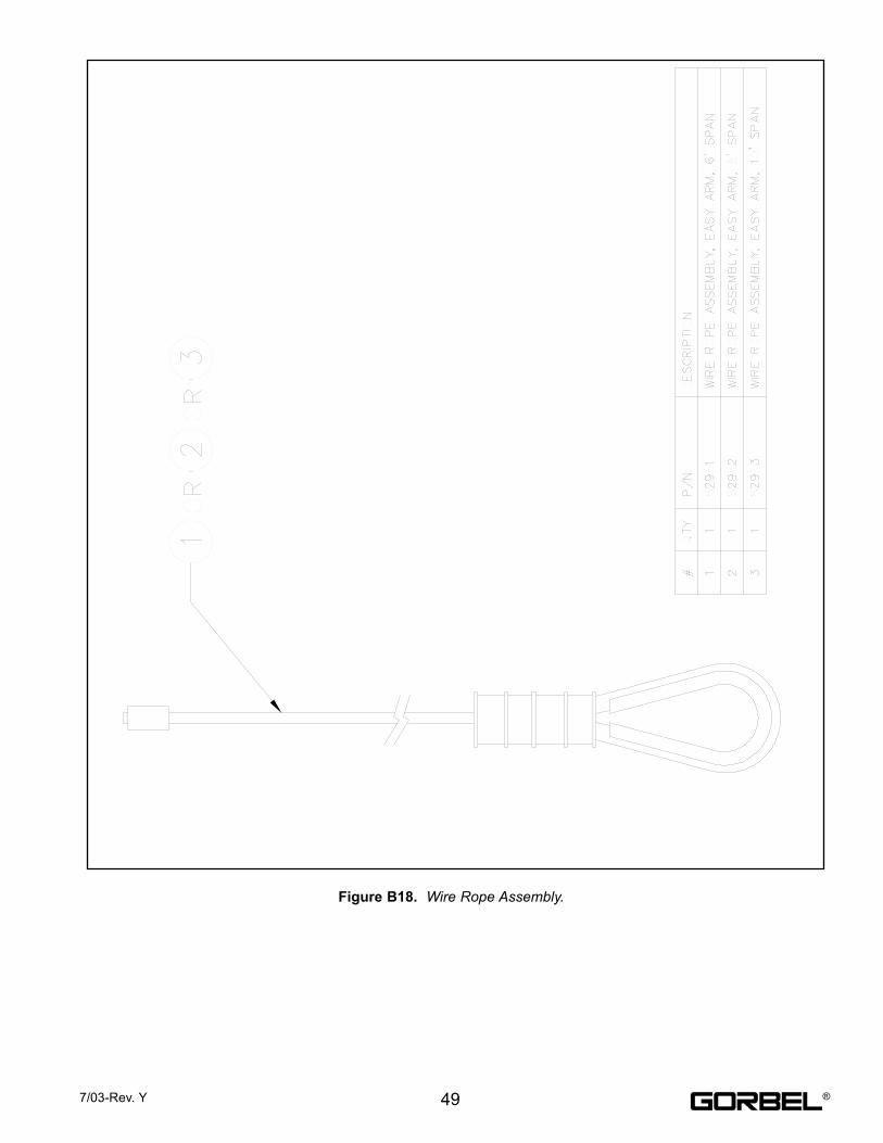
Figure B18. Wire Rope Assembly.
497/03-Rev. Y ®
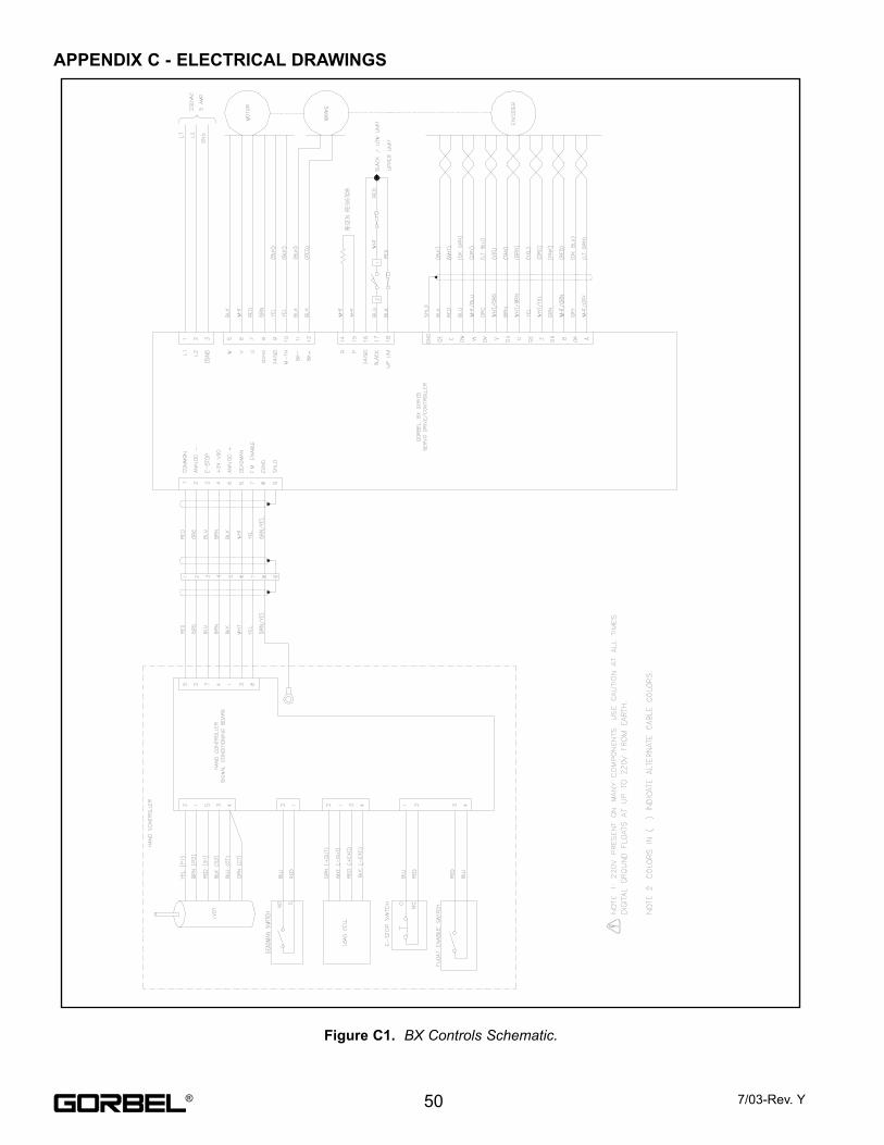
Figure C1. BX Controls Schematic.
APPENDIX C - ELECTRICAL DRAWINGS
50 7/03-Rev. Y®
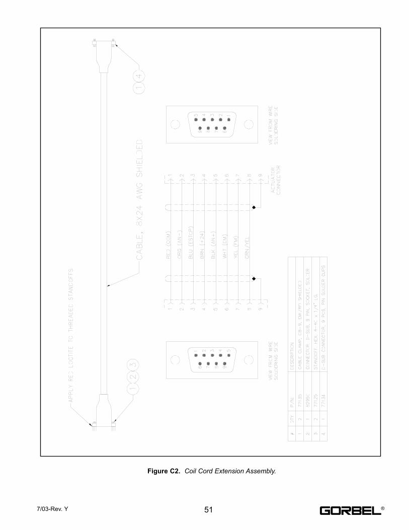
Figure C2. Coil Cord Extension Assembly.
517/03-Rev. Y ®
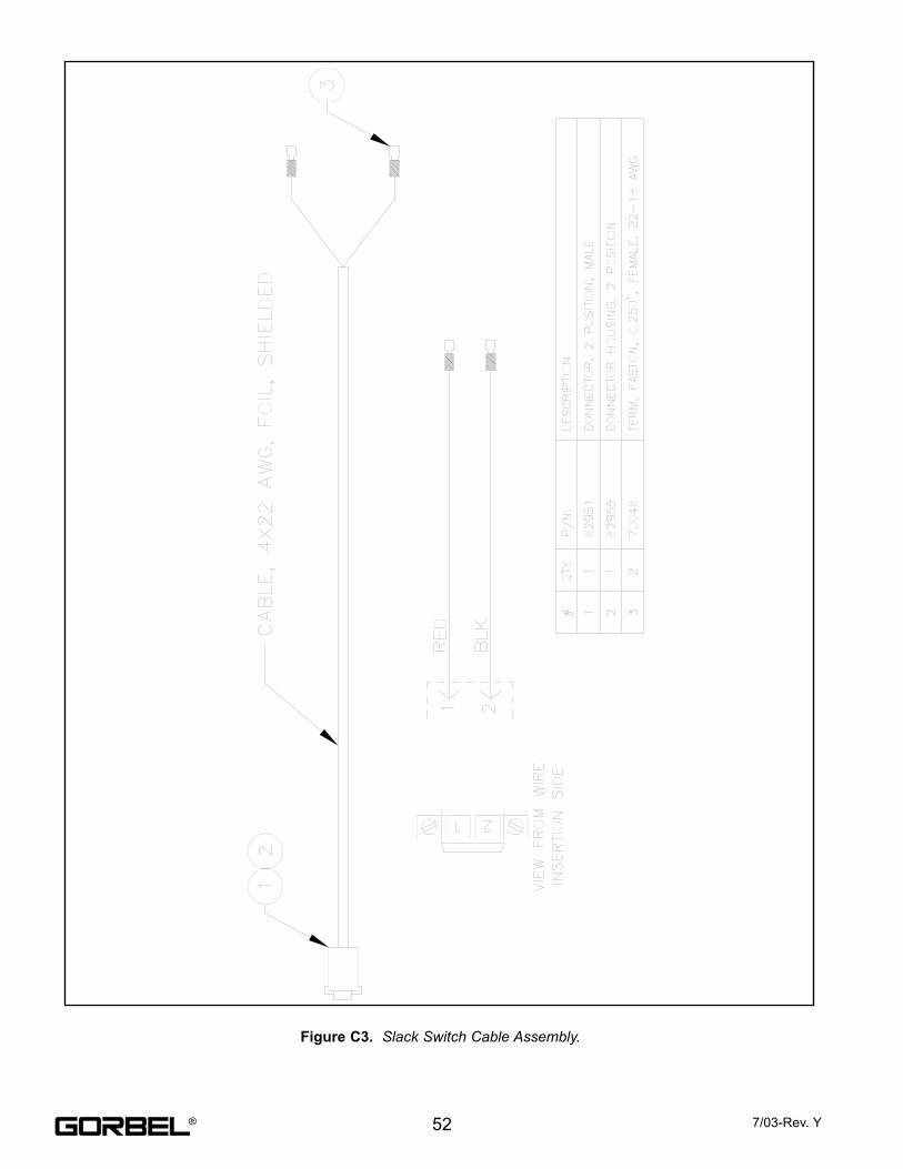
Figure C3. Slack Switch Cable Assembly.
52 7/03-Rev. Y®
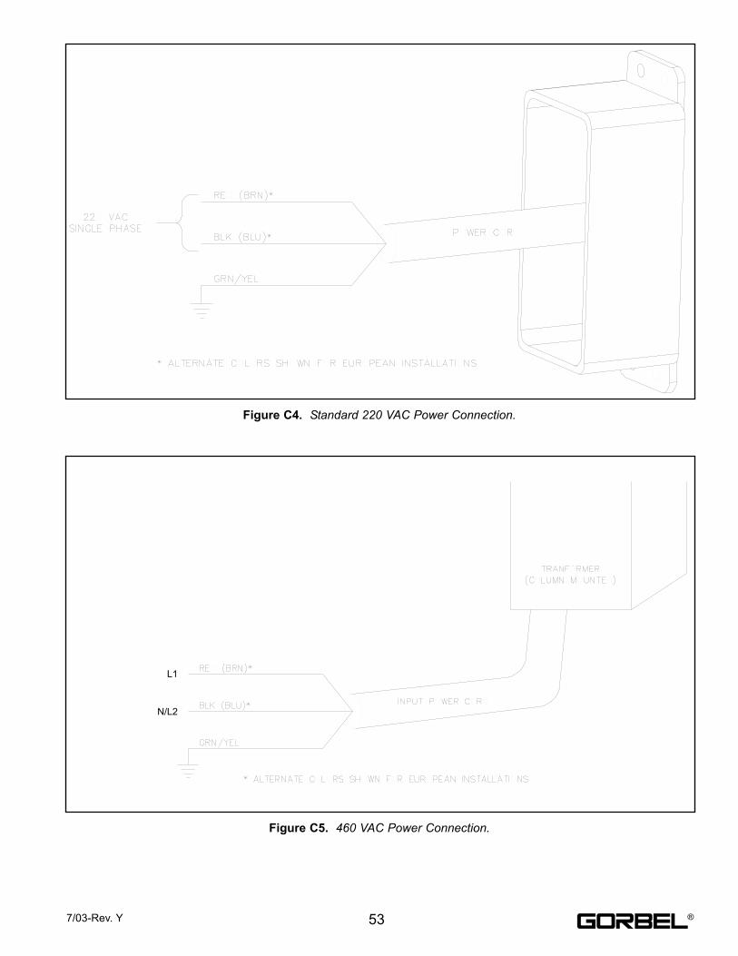
Figure C4. Standard 220 VAC Power Connection.
Figure C5. 460 VAC Power Connection.
537/03-Rev. Y
L1
N/L2
®
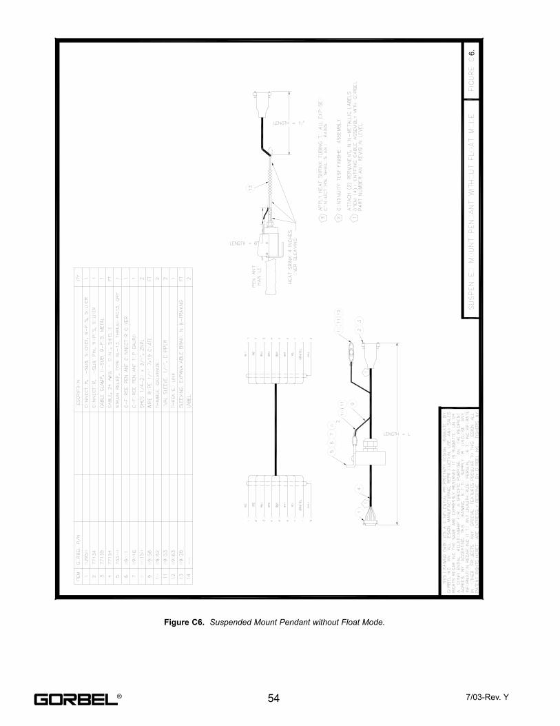
Figure C6. Suspended Mount Pendant without Float Mode.
54 7/03-Rev. Y
6.
®
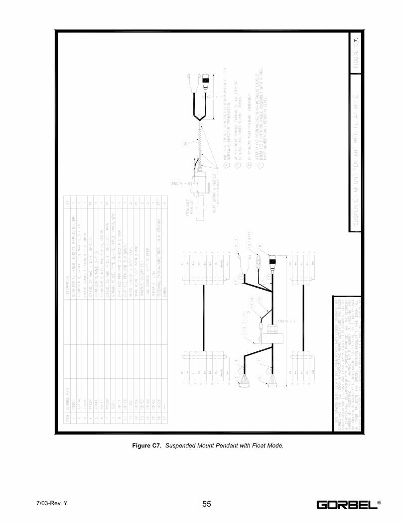
Figure C7. Suspended Mount Pendant with Float Mode.
557/03-Rev. Y
7.
®
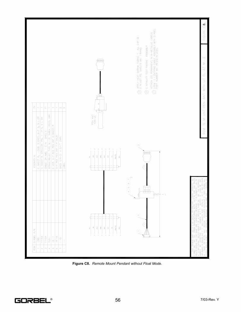
Figure C8. Remote Mount Pendant without Float Mode.
56 7/03-Rev. Y
8.
®
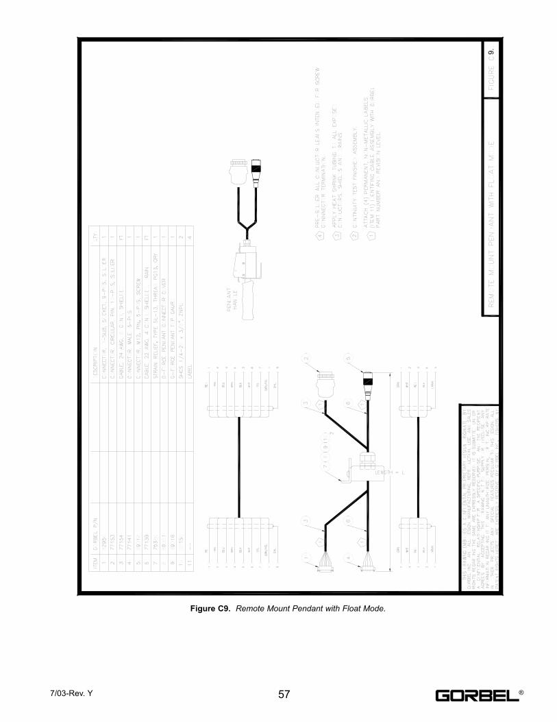
Figure C9. Remote Mount Pendant with Float Mode.
577/03-Rev. Y
9.
®
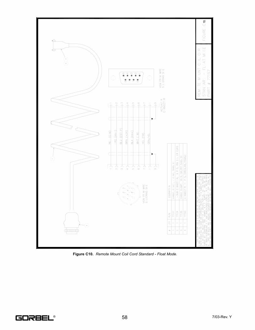
Figure C10. Remote Mount Coil Cord Standard - Float Mode.
58 7/03-Rev. Y
10.
®
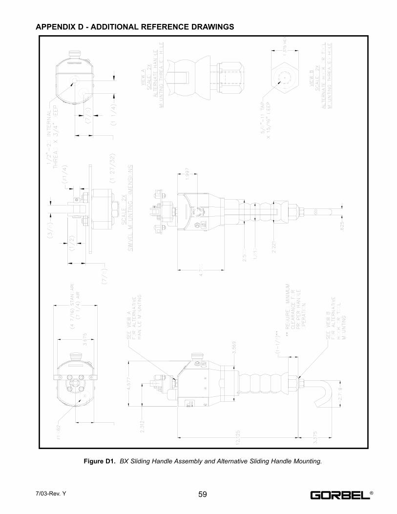
APPENDIX D - ADDITIONAL REFERENCE DRAWINGS
Figure D1. BX Sliding Handle Assembly and Alternative Sliding Handle Mounting.
597/03-Rev. Y ®
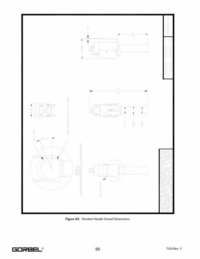
Figure D2. Pendant Handle Overall Dimensions.
60 7/03-Rev. Y®
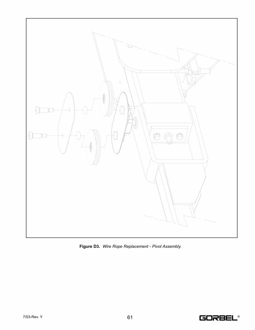
Figure D3. Wire Rope Replacement - Pivot Assembly.
617/03-Rev. Y ®
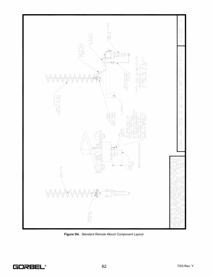
Figure D4. Standard Remote Mount Component Layout.
62 7/03-Rev. Y®
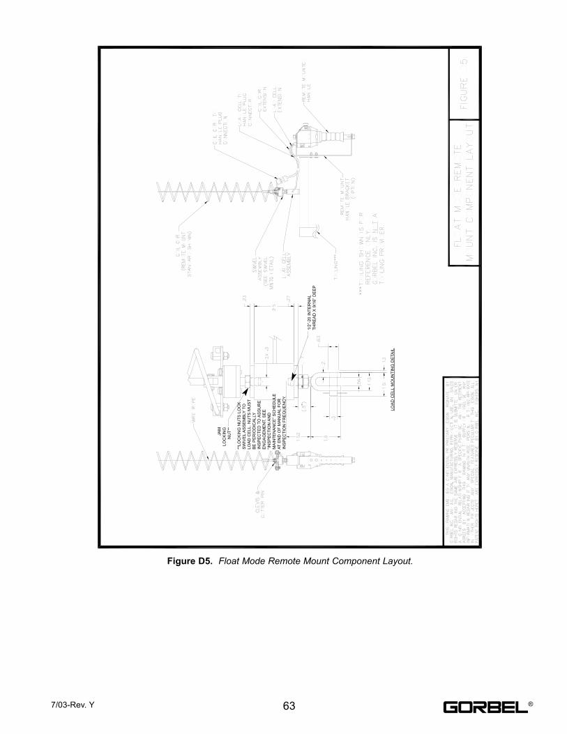
Figure D5. Float Mode Remote Mount Component Layout.
637/03-Rev. Y ®
JA
M
LO
CK
ING
NU
T**
**L
OC
KIN
G N
UT
S L
OC
K
SW
IVE
LA
SS
EM
BLY
TO
LO
AD
CE
LL
. N
UT
S M
US
T
BE
PE
RIO
DIC
AL
LY
INS
PE
CT
ED
TO
AS
SU
RE
EN
GA
GE
ME
NT.
SE
E
“IN
SP
EC
TIO
N A
ND
MA
INT
EN
AN
CE
” S
CH
ED
UL
E
AT
EN
D O
F M
AN
UA
LF
OR
INS
PE
CT
ION
FR
EQ
UE
NC
Y.
1/2
”-2
0 I
NT
ER
NA
L
TH
RE
AD
X 9
/16
” D
EE
P
LO
AD
CE
LL
MO
UN
TIN
G D
ETA
IL
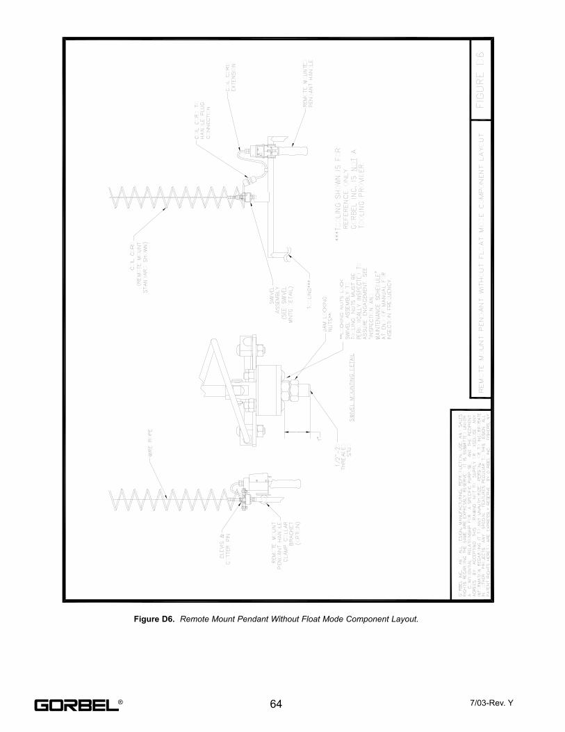
Figure D6. Remote Mount Pendant Without Float Mode Component Layout.
64 7/03-Rev. Y®
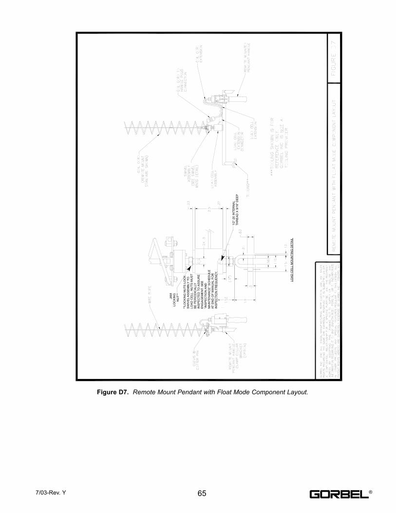
Figure D7. Remote Mount Pendant with Float Mode Component Layout.
657/03-Rev. Y ®
JA
M
LO
CK
ING
NU
T**
**L
OC
KIN
G N
UT
S L
OC
K
SW
IVE
LA
SS
EM
BLY
TO
LO
AD
CE
LL
. N
UT
S M
US
T
BE
PE
RIO
DIC
AL
LY
INS
PE
CT
ED
TO
AS
SU
RE
EN
GA
GE
ME
NT.
SE
E
“IN
SP
EC
TIO
N A
ND
MA
INT
EN
AN
CE
” S
CH
ED
UL
E
AT
EN
D O
F M
AN
UA
LF
OR
INS
PE
CT
ION
FR
EQ
UE
NC
Y.
1/2
”-2
0 I
NT
ER
NA
L
TH
RE
AD
X 9
/16
” D
EE
P
LO
AD
CE
LL
MO
UN
TIN
G D
ETA
IL
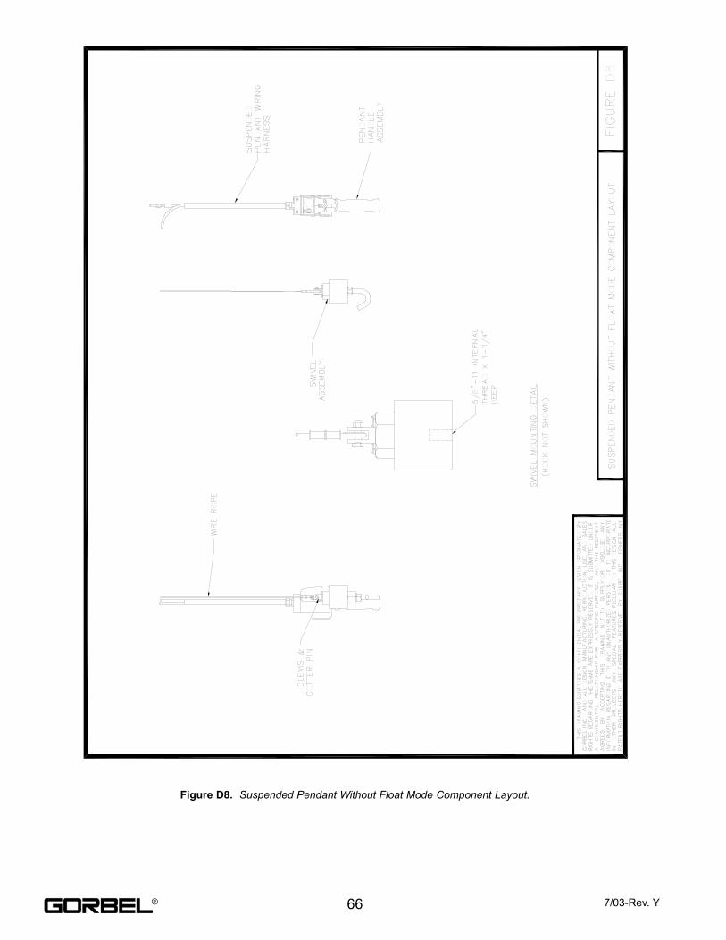
Figure D8. Suspended Pendant Without Float Mode Component Layout.
66 7/03-Rev. Y®
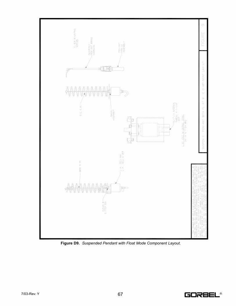
Figure D9. Suspended Pendant with Float Mode Component Layout.
677/03-Rev. Y ®
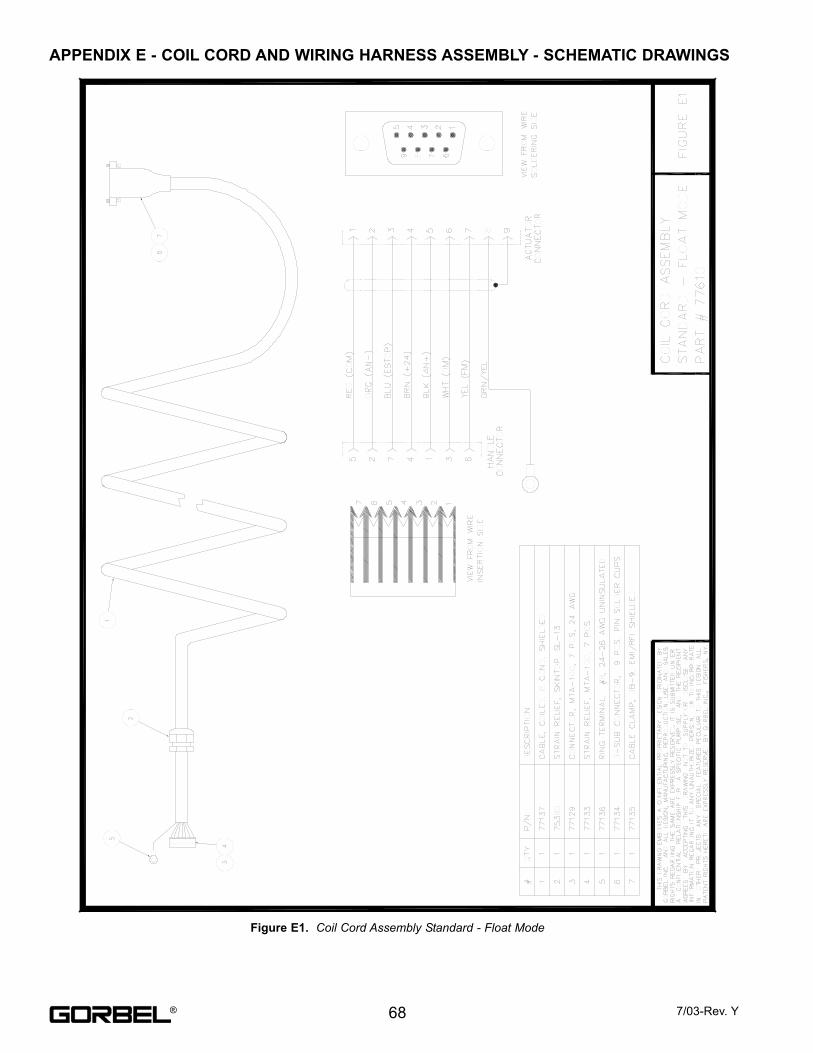
Figure E1. Coil Cord Assembly Standard - Float Mode
68 7/03-Rev. Y
APPENDIX E - COIL CORD AND WIRING HARNESS ASSEMBLY - SCHEMATIC DRAWINGS
®
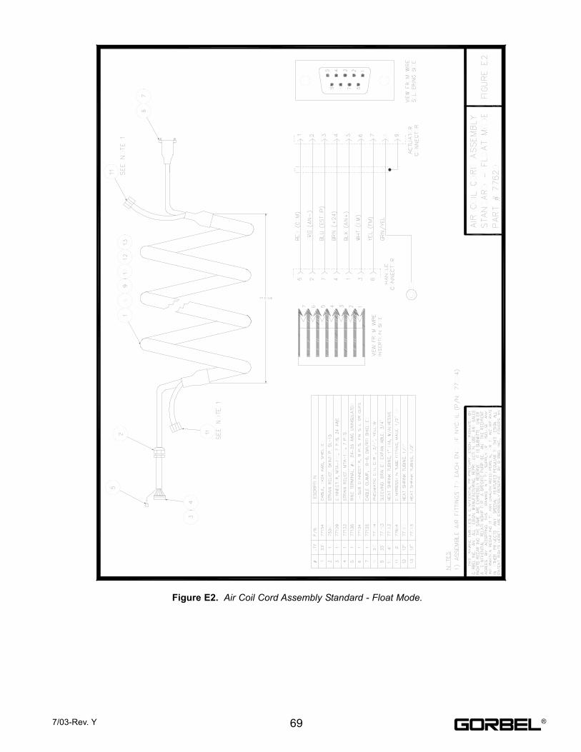
Figure E2. Air Coil Cord Assembly Standard - Float Mode.
697/03-Rev. Y ®
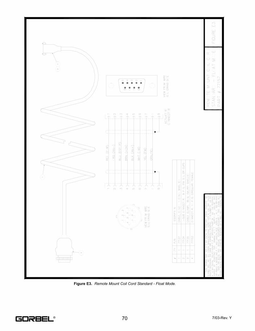
Figure E3. Remote Mount Coil Cord Standard - Float Mode.
70 7/03-Rev. Y®
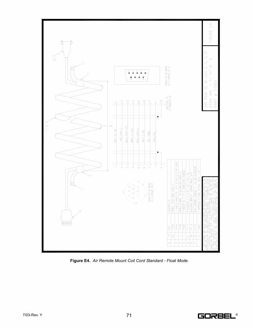
Figure E4. Air Remote Mount Coil Cord Standard - Float Mode.
717/03-Rev. Y ®
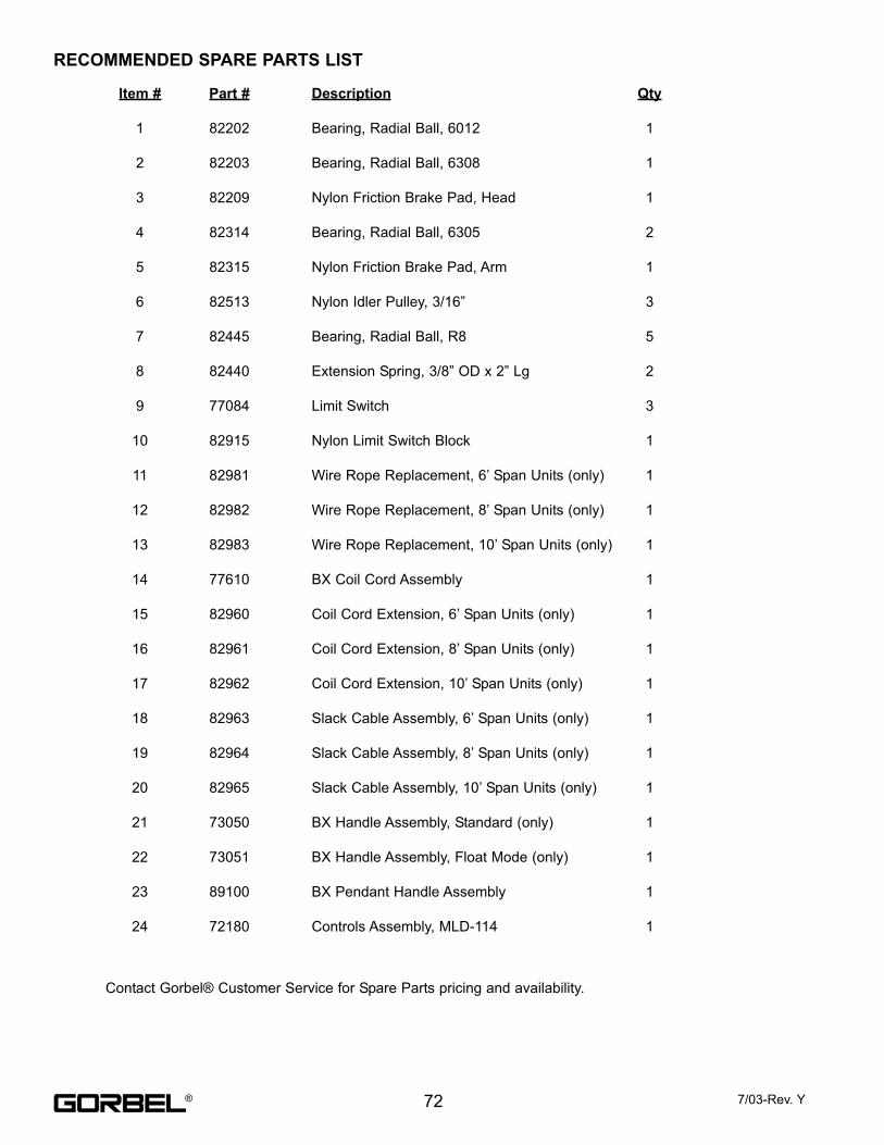
RECOMMENDED SPARE PARTS LIST
Item #
1
2
3
4
5
6
7
8
9
10
11
12
13
14
15
16
17
18
19
20
21
22
23
24
Part #
82202
82203
82209
82314
82315
82513
82445
82440
77084
82915
82981
82982
82983
77610
82960
82961
82962
82963
82964
82965
73050
73051
89100
72180
Description
Bearing, Radial Ball, 6012
Bearing, Radial Ball, 6308
Nylon Friction Brake Pad, Head
Bearing, Radial Ball, 6305
Nylon Friction Brake Pad, Arm
Nylon Idler Pulley, 3/16”
Bearing, Radial Ball, R8
Extension Spring, 3/8” OD x 2” Lg
Limit Switch
Nylon Limit Switch Block
Wire Rope Replacement, 6’ Span Units (only)
Wire Rope Replacement, 8’ Span Units (only)
Wire Rope Replacement, 10’ Span Units (only)
BX Coil Cord Assembly
Coil Cord Extension, 6’ Span Units (only)
Coil Cord Extension, 8’ Span Units (only)
Coil Cord Extension, 10’ Span Units (only)
Slack Cable Assembly, 6’ Span Units (only)
Slack Cable Assembly, 8’ Span Units (only)
Slack Cable Assembly, 10’ Span Units (only)
BX Handle Assembly, Standard (only)
BX Handle Assembly, Float Mode (only)
BX Pendant Handle Assembly
Controls Assembly, MLD-114
Qty
1
1
1
2
1
3
5
2
3
1
1
1
1
1
1
1
1
1
1
1
1
1
1
1
Contact Gorbel® Customer Service for Spare Parts pricing and availability.
72 7/03-Rev. Y®
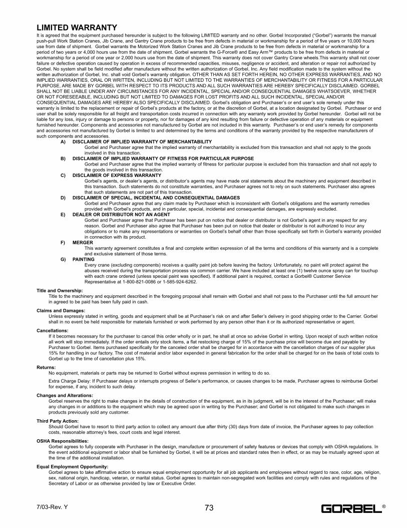
It is agreed that the equipment purchased hereunder is subject to the following LIMITED warranty and no other. Gorbel Incorporated (“Gorbel”) warrants the manual
push-pull Work Station Cranes, Jib Crane, and Gantry Crane products to be free from defects in material or workmanship for a period of five years or 10,000 hours
use from date of shipment. Gorbel warrants the Motorized Work Station Cranes and Jib Crane products to be free from defects in material or workmanship for a
period of two years or 4,000 hours use from the date of shipment. Gorbel warrants the G-Force® and Easy Arm™ products to be free from defects in material or
workmanship for a period of one year or 2,000 hours use from the date of shipment. This warranty does not cover Gantry Crane wheels.This warranty shall not cover
failure or defective operation caused by operation in excess of recommended capacities, misuses, negligence or accident, and alteration or repair not authorized by
Gorbel. No system shall be field modified after manufacture without the written authorization of Gorbel, Inc. Any field modification made to the system without the
written authorization of Gorbel, Inc. shall void Gorbel’s warranty obligation. OTHER THAN AS SET FORTH HEREIN, NO OTHER EXPRESS WARRANTIES, AND NO
IMPLIED WARRANTIES, ORAL OR WRITTEN, INCLUDING BUT NOT LIMITED TO THE WARRANTIES OF MERCHANTABILITY OR FITNESS FOR A PARTICULAR
PURPOSE, ARE MADE BY GORBEL WITH RESPECT TO ITS PRODUCTS AND ALL SUCH WARRANTIES ARE HEREBY SPECIFICALLY DISCLAIMED. GORBEL
SHALL NOT BE LIABLE UNDER ANY CIRCUMSTANCES FOR ANY INCIDENTAL, SPECIAL AND/OR CONSEQUENTIAL DAMAGES WHATSOEVER, WHETHER
OR NOT FORESEEABLE, INCLUDING BUT NOT LIMITED TO DAMAGES FOR LOST PROFITS AND ALL SUCH INCIDENTAL, SPECIAL AND/OR
CONSEQUENTIAL DAMAGES ARE HEREBY ALSO SPECIFICALLY DISCLAIMED. Gorbel’s obligation and Purchaser’s or end user’s sole remedy under this
warranty is limited to the replacement or repair of Gorbel’s products at the factory, or at the discretion of Gorbel, at a location designated by Gorbel. Purchaser or end
user shall be solely responsible for all freight and transportation costs incurred in connection with any warranty work provided by Gorbel hereunder. Gorbel will not be
liable for any loss, injury or damage to persons or property, nor for damages of any kind resulting from failure or defective operation of any materials or equipment
furnished hereunder. Components and accessories not manufactured by Gorbel are not included in this warranty. Purchaser’s or end user’s remedy for components
and accessories not manufactured by Gorbel is limited to and determined by the terms and conditions of the warranty provided by the respective manufacturers of
such components and accessories.
A) DISCLAIMER OF IMPLIED WARRANTY OF MERCHANTABILITY
Gorbel and Purchaser agree that the implied warranty of merchantability is excluded from this transaction and shall not apply to the goods
involved in this transaction.
B) DISCLAIMER OF IMPLIED WARRANTY OF FITNESS FOR PARTICULAR PURPOSE
Gorbel and Purchaser agree that the implied warranty of fitness for particular purpose is excluded from this transaction and shall not apply to
the goods involved in this transaction.
C) DISCLAIMER OF EXPRESS WARRANTY
Gorbel’s agents, or dealer’s agents, or distributor’s agents may have made oral statements about the machinery and equipment described in
this transaction. Such statements do not constitute warranties, and Purchaser agrees not to rely on such statements. Purchaser also agrees
that such statements are not part of this transaction.
D) DISCLAIMER OF SPECIAL, INCIDENTAL AND CONSEQUENTIAL DAMAGES
Gorbel and Purchaser agree that any claim made by Purchaser which is inconsistent with Gorbel’s obligations and the warranty remedies
provided with Gorbel’s products, and in particular, special, incidental and consequential damages, are expressly excluded.
E) DEALER OR DISTRIBUTOR NOT AN AGENT
Gorbel and Purchaser agree that Purchaser has been put on notice that dealer or distributor is not Gorbel’s agent in any respect for any
reason. Gorbel and Purchaser also agree that Purchaser has been put on notice that dealer or distributor is not authorized to incur any
obligations or to make any representations or warranties on Gorbel’s behalf other than those specifically set forth in Gorbel’s warranty provided
in connection with its product.
F) MERGER
This warranty agreement constitutes a final and complete written expression of all the terms and conditions of this warranty and is a complete
and exclusive statement of those terms.
G) PAINTING
Every crane (excluding components) receives a quality paint job before leaving the factory. Unfortunately, no paint will protect against the
abuses received during the transportation process via common carrier. We have included at least one (1) twelve ounce spray can for touchup
with each crane ordered (unless special paint was specified). If additional paint is required, contact a Gorbel® Customer Service
Representative at 1-800-821-0086 or 1-585-924-6262.
Title and Ownership:
Title to the machinery and equipment described in the foregoing proposal shall remain with Gorbel and shall not pass to the Purchaser until the full amount her
in agreed to be paid has been fully paid in cash.
Claims and Damages:
Unless expressly stated in writing, goods and equipment shall be at Purchaser’s risk on and after Seller’s delivery in good shipping order to the Carrier. Gorbel
shall in no event be held responsible for materials furnished or work performed by any person other than it or its authorized representative or agent.
Cancellations:
If it becomes necessary for the purchaser to cancel this order wholly or in part, he shall at once so advise Gorbel in writing. Upon receipt of such written notice
all work will stop immediately. If the order entails only stock items, a flat restocking charge of 15% of the purchase price will become due and payable by
Purchaser to Gorbel. Items purchased specifically for the canceled order shall be charged for in accordance with the cancellation charges of our supplier plus
15% for handling in our factory. The cost of material and/or labor expended in general fabrication for the order shall be charged for on the basis of total costs to
Gorbel up to the time of cancellation plus 15%.
Returns:
No equipment, materials or parts may be returned to Gorbel without express permission in writing to do so.
Extra Charge Delay: If Purchaser delays or interrupts progress of Seller’s performance, or causes changes to be made, Purchaser agrees to reimburse Gorbel
for expense, if any, incident to such delay.
Changes and Alterations:
Gorbel reserves the right to make changes in the details of construction of the equipment, as in its judgment, will be in the interest of the Purchaser; will make
any changes in or additions to the equipment which may be agreed upon in writing by the Purchaser; and Gorbel is not obligated to make such changes in
products previously sold any customer.
Third Party Action:
Should Gorbel have to resort to third party action to collect any amount due after thirty (30) days from date of invoice, the Purchaser agrees to pay collection
costs, reasonable attorney’s fees, court costs and legal interest.
OSHA Responsibilities:
Gorbel agrees to fully cooperate with Purchaser in the design, manufacture or procurement of safety features or devices that comply with OSHA regulations. In
the event additional equipment or labor shall be furnished by Gorbel, it will be at prices and standard rates then in effect, or as may be mutually agreed upon at
the time of the additional installation.
Equal Employment Opportunity:
Gorbel agrees to take affirmative action to ensure equal employment opportunity for all job applicants and employees without regard to race, color, age, religion,
sex, national origin, handicap, veteran, or marital status. Gorbel agrees to maintain non-segregated work facilities and comply with rules and regulations of the
Secretary of Labor or as otherwise provided by law or Executive Order.
LIMITED WARRANTY
737/03-Rev. Y ®
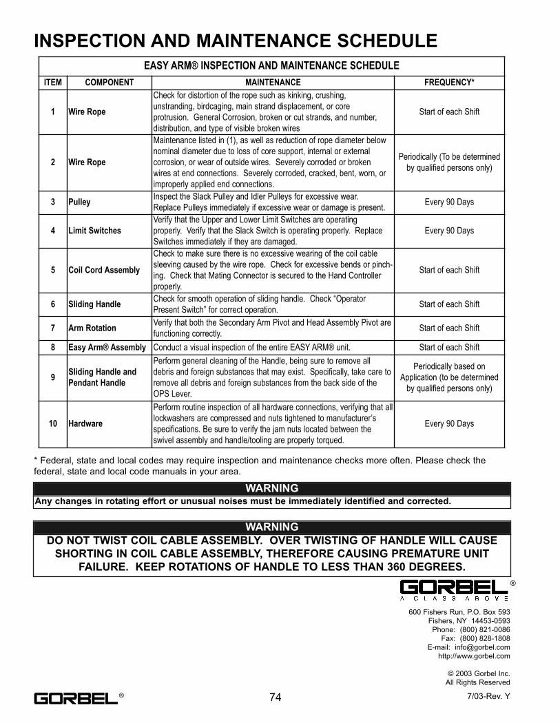
* Federal, state and local codes may require inspection and maintenance checks more often. Please check the
federal, state and local code manuals in your area.
EASY ARM® INSPECTION AND MAINTENANCE SCHEDULEITEM COMPONENT MAINTENANCE FREQUENCY*
1 Wire Rope
Check for distortion of the rope such as kinking, crushing,unstranding, birdcaging, main strand displacement, or coreprotrusion. General Corrosion, broken or cut strands, and number,distribution, and type of visible broken wires
Start of each Shift
2 Wire Rope
Maintenance listed in (1), as well as reduction of rope diameter belownominal diameter due to loss of core support, internal or externalcorrosion, or wear of outside wires. Severely corroded or brokenwires at end connections. Severely corroded, cracked, bent, worn, orimproperly applied end connections.
Periodically (To be determinedby qualified persons only)
3 Pulley Inspect the Slack Pulley and Idler Pulleys for excessive wear.Replace Pulleys immediately if excessive wear or damage is present. Every 90 Days
4 Limit SwitchesVerify that the Upper and Lower Limit Switches are operatingproperly. Verify that the Slack Switch is operating properly. ReplaceSwitches immediately if they are damaged.
Every 90 Days
5 Coil Cord Assembly
Check to make sure there is no excessive wearing of the coil cablesleeving caused by the wire rope. Check for excessive bends or pinch-ing. Check that Mating Connector is secured to the Hand Controllerproperly.
Start of each Shift
6 Sliding Handle Check for smooth operation of sliding handle. Check “OperatorPresent Switch” for correct operation. Start of each Shift
7 Arm Rotation Verify that both the Secondary Arm Pivot and Head Assembly Pivot arefunctioning correctly. Start of each Shift
8 Easy Arm® Assembly Conduct a visual inspection of the entire EASY ARM® unit. Start of each Shift
9 Sliding Handle andPendant Handle
Perform general cleaning of the Handle, being sure to remove alldebris and foreign substances that may exist. Specifically, take care toremove all debris and foreign substances from the back side of theOPS Lever.
Periodically based onApplication (to be determined
by qualified persons only)
10 Hardware
Perform routine inspection of all hardware connections, verifying that alllockwashers are compressed and nuts tightened to manufacturer’sspecifications. Be sure to verify the jam nuts located between theswivel assembly and handle/tooling are properly torqued.
Every 90 Days
INSPECTION AND MAINTENANCE SCHEDULE
WARNING Any changes in rotating effort or unusual noises must be immediately identified and corrected.
WARNING
DO NOT TWIST COIL CABLE ASSEMBLY. OVER TWISTING OF HANDLE WILL CAUSE
SHORTING IN COIL CABLE ASSEMBLY, THEREFORE CAUSING PREMATURE UNIT
FAILURE. KEEP ROTATIONS OF HANDLE TO LESS THAN 360 DEGREES.
600 Fishers Run, P.O. Box 593
Fishers, NY 14453-0593
Phone: (800) 821-0086
Fax: (800) 828-1808
E-mail: [email protected]
http://www.gorbel.com
© 2003 Gorbel Inc.
All Rights Reserved
74 7/03-Rev. Y®
®