Embed Size (px)
Citation preview

E-2
CRW/CRWM
Crossed Roller Way is a linear motion rolling guide in which a roller cage is incorporated betweentwo ways with V-shaped raceways. As the cylindrical rollers are alternately crossed, Crossed RollerWay can receive loads in any direction and can achieve very smooth linear motion with very highaccuracy. Wide variations in size are available for selections suitable for each application.
Standard type and module typeTwo types are available: the standard type and themodule type. In the standard type four ways and tworoller cages are used as one set, while in the moduletype two inner ways are integrated into a single piece.
High carbon chromium bearing steeltype and stainless steel type
Standard types include high carbon chromium bearingsteel type and stainless steel type.
Easy mountingThe mounting holes of the ways are female thread holeswith a counter bore. So the mounting method isflexible, allowing the ways to be mounted either byusing the female threads of the ways together with boltsinserted through the holes prepared on machines or byusing the female threads prepared on machines.Mounting structure can be designed freely.Two inner ways of module type are integrated into a singlepiece. The mounting structure can be made simple and,furthermore, as errors from extra machining of themounting parts can be avoided, accuracy of linear motioncan be improved.
U.S. PATNET No. 4,697,935
Very smooth operationPrecisely finished raceways are combined with rollercages, in which the length of super precise rollers isaccurately controlled to avoid skewing. Very smoothlinear motion with very little frictional resistance and freefrom stick-slip can be achieved.
CRW CRWM
Note : One set consists of four ways and two roller cages. Note : One set consists of one center way, two ways and two roller cages.
End screw
Way
Way
Cage Cylindrical roller
End screw Center way
Way
Cage Cylindrical roller
Roller cage
Structure of Crossed Roller Way
Roller cage
U.S. PATENTED
Crossed Roller Way
465-511 05.2.25 11:00 AM ページ E-2

EC
RW
, C
RW
M
E-31N=0.102kgf=0.2248lbs.1mm=0.03937inch
Crossed Roller Way series
Shape
Standard type
Model code
Module type
CRWCRW…SL
CRWM
Remark : Models with "SL" are stainless steel type.
Crossed Roller Way
465-511 05.2.25 11:00 AM ページ E-3

Standard type
Standard type
Module type
SPModule type CRWM 200×150 /U3
3
3
3
C20
SL
SPCRWM 150 /UC20
SPCRW 250×300 C36
CRW /UC20 SL SP
/U
Part code
2
3
4
5
6
7
1 Series�
Size of rolling guide
Length of way
Number of cylindrical rollers
Material
Accuracy class
Special specification
150―�
―�
―�
―�
Identification number and specificationThe specification of Crossed Roller Way is indicated by the identification number, consisting of a model code, a size, a part code, a material symbol, a classification symbol and any supplemental codes.
Size
Material symbol
Classification symbol
Supplemental code
Model code
E-4
465-511 05.2.25 11:00 AM ページ E-4

EC
RW
, C
RW
M
For available models and sizes, see Table 1.
2 Size of rolling guide
Indicate the length of way in mm. Ways with different lengths can be combined. For the lengths of ways, see the table of dimensions. To indicate a combination of ways with different lengths, see "Combination of way lengths ".
3 Length of way
The number of cylindrical rollers incorporated in one cage is indicated. When this number is not indicated, the number of cylindrical rollers shown in the table of dimensions are incorporated in one cage.
4 Number of cylindrical rollers
○�
○×○�
No symbol
C○�
Standard type :CRW�
Module type :CRWM 1 Series
―�
―�
―�
―�
Combination of way lengths
Combination for the standard typeOne set consists of two short ways and two long ways together with two roller cages.As standard, the number of rollers in one cage is the number of rollers for the shorter of the two way lengths shown in the dimension tables. If a different number of rollers is required, indicate it in the identification number.
Example CRW 6 - 300 × 400 C24
24 pcs. of rollers incorporated in one cageLong way length : 400 mm
Short way length : 300 mm
Combination for the module typeOne set consists of one center way, two ways together with two roller cages.As standard, the number of rollers in one cage is the number of rollers for the shorter of the two way lengths shown in the dimension tables. If a different number of rollers is required, indicate it in the identification number.
Example CRWM 3 - 200 × 150 C20
20pcs. of rollers incorporated in one cageWay length : 150 mm
Center way length : 200 mm
E-51N=0.102kgf=0.2248lbs.1mm=0.03937inch
465-511 05.2.25 11:00 AM ページ E-5

For applicable material types, see Table 1.High carbon steel made : No symbol
Stainless steel made : SL5 Material
Standard : No symbol
Super precision : SP6 Accuracy class
Table 1 Types and sizes
For the allowable values of parallelism of the raceway to the reference mounting surface and of parallelism between two raceways of CRWM, see Fig. 1.
Fig. 1 Accuracy of Crossed Roller Way
△
△
△
△
△
△
△
△
△
△
△
△
△
™™™™
™™™
™™™™™™™™™™
™™™™™ーーーーー�
™™™™ーーーーーー�
1 2 3 4 6 912151824
Stainless steel made
Module type
High carbon steel madeHigh carbon steel made
Standard typeType
Size
CRW
A
A A
A
A
BB /L�
/L�
/L�
/L�
/L�
CRWM
SP
10
8
6
4
2
0 200 400 600 800 1000 1200
Way length L mm
Par
alle
lismΔμm
E-6
465-511 05.2.25 11:00 AM ページ E-6

EC
RW
, C
RW
M
For applicable special specifications, see Table 2. When several special specifications are required, see Table 3. For details of special specifications, see page E-8.
7 Special specification
Table 2 Special specifications
Note( 1 ) : Not applicable to size 1 and 2 models.
( 2 ) : Not applicable to size 1, 2, 3 and 4 models.
( 3 ) : Not applicable to size 1 models.
Remark : In the table, the mark △ indicates that it is applicable to some sizes.
Special mounting screws
High rigidity roller cage
End stopper SA
End stopper SB
Wiper seal
BMSASBU
△ ( 1 )�
△ ( 2 )�
△ ( 3 )�
△ ( 3 )�
△ ( 3 )
△ ( 1 )�
ー�
△ ( 3 )�
△ ( 3 )�
△ ( 3 )
ー�
△ ( 2 )�
△ ( 3 )�
△ ( 3 )�
△ ( 3 )
Supplementalcode
�
M
SA
SB
U
™�
™�
™�
™�
B
™�
™�
™�
M
ー�
ー�
SA
ー�
SB
Remark 1 : In the table, the mark -- indicates that this combination can not be made. 2 : When several special specifications are required, arrange the supplemental codes alphabetically.
™™™™™™™™™™
™™™™™
™™™™
Table 3 Combinations of special specifications
High carbon steel made Stainless steel made
Standard typeSpecial specification
Module type
High carbon steel made
E-71N=0.102kgf=0.2248lbs.1mm=0.03937inch
465-511 05.2.25 11:00 AM ページ E-7

Special mounting screws /B
Since the way at the adjusting side moves when the preload is set, some clearance between the mounting screw and the mounting hole is necessary. However, if sufficient clearance can not be provided or if the mounting screw is fixed from the way side to the table as shown in Fig. 2, special mounting screws may be needed.Further, if the positioning accuracy of mounting holes in table or bed are not good, special screws can also be used. The special mounting screws are delivered as appended parts upon request, but available in carbon steel type only.
Table 4 Dimensions of special mounting screws
3469
12151824
34568
101214
1215203040455070
568
1217161926
2.33.13.94.66.27.99.6
11.2
5 6 8 8.511.5141619.5
M 3M 4M 5M 6M 8M10M12M14
Size
unit : mm
Screw size d D H L S
Fig. 2 Mounting example with special mounting screw
Special specificationsDetails of special specifications of Crossed Roller Way are shown below. Indicate any specification by adding the supplemental code to the end of the identification number.
Screw size
L
d
D
S
H
E-8
465-511 05.2.25 11:00 AM ページ E-8

EC
RW
, C
RW
M
High rigidity roller cage /M
High rigidity cages made of copper alloy, which are suitable for use in vertical applications, are optionally available. This cage is designed to prevent rollers from falling out in one direction. (See Fig. 3.)For vertical usage, it is recommended to use this cage together with the end stopper SB.
Fig. 3 High rigidity cage
End stopper SA /SA
When the cage is stroked frequently or subjected to vibration or unevenly distributed load, the cage position may shift while in operation. It is recommended, in such cases, to replace the end screw with the end stopper SA.Size 1 models are assembled with stoppers similar to the SA end stopper as standard.
Table 5 Dimensions of end stopper SA
2
3
4
6
9
2
2
3
3
4
12
15
18
24
11
14
14
16
5
6
6
6
4.5
5
7
8
10
Size
unit : mm
t1 t2 Size t1 t2
t1
t2
E-91N=0.102kgf=0.2248lbs.1mm=0.03937inch
465-511 05.2.25 11:00 AM ページ E-9

End stopper SB /SB
When the high rigidity cage is used on a vertical axis, the end screw is replaced with the end stopper SB to limit the stroking of the cage at the way end.The end stopper SB can not be mounted on all ends of the ways in the assembly. Fig. 4 shows the standard mounting arrangement. The mounting arrangement can be changed by loosening screws and resetting the end stoppers.
Table 6 Dimensions of end stopper SB
2
3
4
6
9
2
2
3
3
4
12
15
18
24
11
14
14
16
5
6
6
6
Size
unit : mm
t1 t2 Size t1 t2
4.5
5
7
8
10
Fig. 4 Arrangement of end stoppers SB
t1
t2
E-10
465-511 05.2.25 11:00 AM ページ E-10

EC
RW
, C
RW
M
Wiper seal /U
The end screw is replaced with the wiper seal to prevent foreign particles from intruding into the raceways. The wiper seal also serves as the end stopper providing the same function as the end stopper SB. The wiper seal cannot be mounted on every way end. Fig. 5 shows the standard mounting arrangement. The mounting arrangement can be changed by loosening screws and resetting the wiper seals.
Table 7 Dimensions of wiper seal
Fig. 5 Arrangement of wiper seals
2
3
4
6
9
12
15
18
24
11
14
14
16
4.5
5
7
8
10
Size
unit : mm
t1 t2 Size t1 t2
8.5
11
11
11
4
4
6
6
7.5
t1
t2
E-111N=0.102kgf=0.2248lbs.1mm=0.03937inch
465-511 05.2.25 11:00 AM ページ E-11

Basic dynamic load rating CThe basic dynamic load rating is defined as the constant load both in direction and magnitude under which a group of identical Crossed Roller Ways are individually operated and 90% of the units in the group can travel 100 x 103 meters free from material damage due to rolling contact fatigue.
Basic static load rating C0
The basic static load rating is defined as the static load that gives a prescribed constant contact stress at the center of the contact area between the rolling element and raceway receiving the maximum load.
Allowable load FThe allowable load is a load under which the sum of elastic deformations of the rolling element and the raceway in the contact area subjected to the maximum contact stress is small enough to guarantee accuracy and smooth rolling movement. Therefore, when very smooth and highly accurate linear motion is required, make sure that the applied load is well within the allowable load value.
Calculation of load ratings and allowable loadIn Crossed Roller Way, the number of cylindrical rollers sharing a load differs according to the load direction. Therefore, it is necessary to obtain load ratings and allowable load for each direction.The basic dynamic load rating CU, basic static load rating C0U and allowable load FU shown in the table of dimensions indicate values per one roller.The basic dynamic load rating C, basic static load rating C0 and allowable load F of Crossed Roller Way are obtained from the formulae shown in Tables 8.1 and 8.2.
Summarized descriptions of load ratings of Crossed Roller Way are given below. For details of load rating definitions and load calculations, see "General description".
Load Rating and Allowable LoadLoad Rating and Allowable Load
E-12
465-511 05.2.25 11:00 AM ページ E-12

EC
RW
, C
RW
M
Table 8.1 Calculation formulae for load ratings and allowable loads of CRW
Note( 1 ) : When using one set of CRW type (four ways and two roller cages) in parallel in this load direction, use formulae (7), (8) and (9) in Table 8.2.
Load condition
Basic dynamic load rating C N Cr = ( -1)2p 1/36 ( )3/4CU …�
Basic static load rating C0 N
Allowable load F N
: Basic dynamic load rating for upward / downward load, N: Basic dynamic load rating for lateral load, N: Basic static load rating for upward / downward load, N: Basic static load rating for lateral load, N: Allowable load for upward / downward load, N�: Allowable load rating for lateral load, N: Number of cylindrical rollers incorporated in one roller cage (Disregard any decimal for Z/2)�: Pitch between cylindrical rollers, mm: Basic dynamic load rating per one roller, N�: Basic static load rating per one roller, N: Allowable load per one roller, N
: Basic dynamic load rating for upward / downward load, N: Basic dynamic load rating for lateral load, N: Basic static load rating for upward / downward load, N: Basic static load rating for lateral load, N: Allowable load for upward / downward load, N�: Allowable load rating for lateral load, N: Number of cylindrical rollers incorporated in one roller cage (Disregard any decimal for Z/2)�: Pitch between cylindrical rollers, mm: Basic dynamic load rating per one roller, N�: Basic static load rating per one roller, N: Allowable load per one roller, N
Meaning of symbols
Upward/downward load(1)� Lateral load
Z�2�
Z�2�
Z�2�Ca = ( -1)2p
1/36( )3/427/9CU …
C0r = ( )C0U …………………………�Z�2� C0a = 2( )C0U …………………………�
Z�2�Fr = ( )FU ……………………………� Fa = 2( )FU ……………………………�
Table 8.2 Calculation formulae for load ratings and allowable loads of CRWM
Z�2�
Z�2�
Z�2�
Load
Load
Load Load
1/2Load 1/2Load
Load
Load Load
(2)�
(1)�
(3)�
(5)�
(10)�
(6)�
Z�2�Ca = ( -1)2p
1/36( )3/427/9CU …… Z�2�
(4)�
Load condition
Basic dynamic load rating C N
Basic static load rating C0 N
Allowable load F N
Meaning of symbols
Upward/downward load Lateral load
Z�2� C0a = 2( )C0U ………………………�
Z�2�Fr = 2( )FU …………………………�
C0r = 2( )C0U ………………………�
Fa = 2( )FU …………………………�
Z�2�
Z2�
(8)�
(9)�
(11)�
(12)�
Z�2�Cr = ( -1)2p
1/36( )3/427/9CU …�Z�2�
(7)�
Cr Ca C0r C0a
Fr Fa Zp
CU C0U FU
Cr Ca C0r C0a
Fr Fa Zp
CU C0U FU
E-131N=0.102kgf=0.2248lbs.1mm=0.03937inch
465-511 05.2.25 11:00 AM ページ E-13

Stroke length and number of rollers
When selecting the specification of Crossed Roller Way, stroke length and number of rollers should be considered as well as the accuracy, load ratings and allowable load.
Stroke length of Crossed Roller Way is related to the way length and number of rollers in a roller cage, etc.Therefore, selection procedure is as follows while considering the operating stroke length and applied loads.
Way length is generally more than 1.5 times of operating stroke length and is obtained from the following formula.
where, L: Way length, mm
S: Operating stroke length, mm
�
It is suggested that the operating stroke length is 80% or less of the maximum stroke length. The maximum stroke length is obtained from the following formula.
�
�
where, S1: Maximum stroke length, mm
S: Operating stroke length, mm
S1 ≧ S ……………………(11)�10.8
where, LR: Allowable distance between rollers
at both ends in one cage, mm
L: Way length, mm
S1: Maximum stroke length, mm
Calculation of way length1
Calculation of maximum stroke length2
Calculation of cage length and number of rollers3
LR = L- ……………………�S1
2
L ≧ 1.5S ………………………(10)�
S
L≧1.5S
Selection of SpecificationSelection of Specification
Cage length is determined by the way length and maximum stroke length.In calculation of cage length, the calculation method is different according to the specification of end screws, end stoppers, etc.
�
(1) With standard end screws or end stoppers SA (except size 1 models)The distance between rollers at both ends in one cage is that way length minus half of maximum stroke length as in the following formula.
(12)�
L S1
S1/2
L
LR S1/2
E-14
465-511 05.2.25 11:00 AM ページ E-14
EC
RW
, C
RW
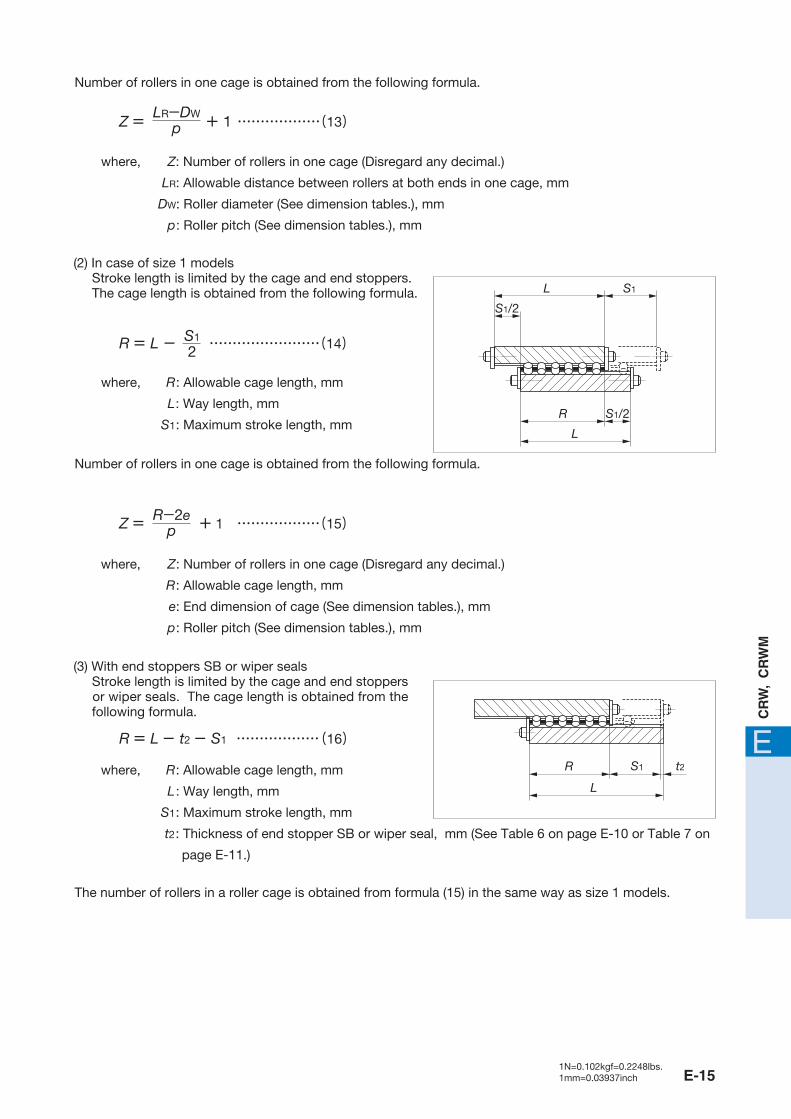
M where, R : Allowable cage length, mm
L : Way length, mm
S1 : Maximum stroke length, mm
t2 : Thickness of end stopper SB or wiper seal, mm (See Table 6 on page E-10 or Table 7 on
page E-11.)
Number of rollers in one cage is obtained from the following formula.
Number of rollers in one cage is obtained from the following formula.
where, Z: Number of rollers in one cage (Disregard any decimal.)
LR: Allowable distance between rollers at both ends in one cage, mm
DW: Roller diameter (See dimension tables.), mm
p : Roller pitch (See dimension tables.), mm
where, Z : Number of rollers in one cage (Disregard any decimal.)
R : Allowable cage length, mm
e: End dimension of cage (See dimension tables.), mm
p : Roller pitch (See dimension tables.), mm
where, R : Allowable cage length, mm
L : Way length, mm
S1 : Maximum stroke length, mm
(2) In case of size 1 models Stroke length is limited by the cage and end stoppers. The cage length is obtained from the following formula.
(3) With end stoppers SB or wiper seals Stroke length is limited by the cage and end stoppers or wiper seals. The cage length is obtained from the following formula.
Z = + 1 ………………(15)�R-2e
p
R = L - ……………………(14)�
R = L - t2 - S1 ………………(16)�
Z = + 1 ………………(13)�LR-DW
p
S1
2
L S1
S1/2
S1/2
L
R
R
L
S1 t2
The number of rollers in a roller cage is obtained from formula (15) in the same way as size 1 models.
E-151N=0.102kgf=0.2248lbs.1mm=0.03937inch
465-511 05.2.25 11:00 AM ページ E-15

Calculation example
�
F = 2 FU = 2 ×769 = 15380Z2(�) 20
2(�)
Calculation of way length1
Calculation of maximum stroke length2
Calculation of number of rollers3
Calculation of allowable load4
Determination of specification5
10.8
10.8
S1
22442
LR-DWp
178-69
L ≧ 1.5S = 1.5×195 = 292.5
S1 ≧ S = ×195 ≒ 244
LR = L- = 300- = 178
Z = +1 = +1 ≒ 20.1
From formula (9) in Table 8.2 on page E-13, allowable load F in parallel usage is; (allowable load per one roller FU = 764 N from dimension tables)
In the calculation result, the allowable load F is larger than the applied load P = 7000 N. Therefore, this model can be used within the allowable load. If the applied load exceeds the calculated allowable load, it is necessary to consider increasing the way length and number of rollers, or to select a model with larger diameter rollers.
Therefore, number of rollers Z = 20 in one cage is obtained by disregarding any decimal.
As a result of the above calculations, CRW 6-300 with 20 rollers is suitable. The selected model number is CRW 6-300 C20.
From formula (13), number of rollers in one cage is; (DW = 6 mm and p = 9 mm from dimension tables)
From formula (12), allowable distance between rollers at both ends in one cage LR is;
From formula (11), maximum stroke length S1 is;
Therefore, standard way length L = 300 mm is selected from dimension tables.
From formula (10), way length L is;
Model…………………………………………………………… CRW 6 Applied load………………………………………………………P = 7000 N� Stroke length…………………………………………………… S = 195 mm� For parallel use of Crossed Roller Ways under the above specified conditions (See Fig. 12 on page E-21.), select the suitable specification.
E-16
465-511 05.2.25 11:00 AM ページ E-16

EC
RW
, C
RW
M
Oil or grease is used as a lubricant for Crossed Roller Way. Oil is generally used for high speed or low friction operation. On the other hand, grease is used when operating speed is low. In case of grease lubrication, a good quality lithium-soap base grease is recommended. When operation speed is low and load is light, coat the raceways with grease before use and relubricate periodically. Structure shown in Fig. 6 makes the relubrication easy.Crossed Roller Ways are finished very accurately. However, if dust or foreign particles intrude, life and accuracy will be adversely affected. In order to prevent the intrusion of dust, dirt, water, etc., it is recommended to use non-contact type shields (labyrinth seal) as shown in Fig. 7 or contact type wiper seals shown in Fig.8 at the outside of installed unit.
Fig. 6 Example of lubrication method
Fig. 7 Example of non-contact type shield (Labyrinth seal)
Fig. 8 Example of wiper seal
Lubrication and Dust ProtectionLubrication and Dust Protection
E-171N=0.102kgf=0.2248lbs.1mm=0.03937inch
465-511 05.2.25 11:00 AM ページ E-17

Check whether the specification of selected Crossed Roller Way meets the requirements for the application of the machine or equipment.
Crossed Roller Way is a high precision product, so handle it with care. The cage can be modified by cutting it to the required cage length. When cutting, do not deform the cage.
The general configurations of mating mounting surfaces for CRW and CRWM are shown in Figs. 9.1 and 9.2, respectively. Accuracy of the mating mounting surfaces is, in general, as shown in Table 9. The accuracy of mating mounting surfaces directly affects the operating accuracy and performance of Crossed Roller Way. If very high operating accuracy is required, higher accuracy of mating mounting surfaces than the values shown in Table 9 may be needed.
Table 9 Accuracy of mating mounting surfaces
Specification of Crossed Roller Way1
Handling of Crossed Roller Way2
Accuracy of mating mounting surfaces3
Fig. 9.1 Example of mating mounting surfaces for CRW Fig. 9.2 Example of mating mounting surfaces for CRWM
AC A
AA BB
A
AC
Precautions for UsePrecautions for Use
surfaceA
・Flatness Flatness of these surfaces directly affects preload.
The value of flatness should be equal or nearly equal to the value of parallelism in Fig. 1 on page E-6.・Squareness Squareness to surface affects the rigidity of assembled unit in the preload direction.
Consequently, a high accuracy finish is necessary.A
・This accuracy directly affects the operating accuracy.Flatness of surface (four places) should be equal or nearly equal to the value of parallelism in Fig. 1 on page E-6.
A
and surfaces B C
E-18
465-511 05.2.25 11:00 AM ページ E-18

EC
RW
, C
RW
M
Preload adjusting screws are generally used for setting preload, as shown in Fig. 10. The size of the preload adjusting screws are the same as that of the mounting screws for the ways. The position of the preload adjusting screws is at the same position as the mounting screws of the ways. For centering, use half of way height H. Preload amounts differ according to the application of machine or equipment. Excessive preloads deteriorate life and often damage the raceways. Therefore, zero or minimal preload is recommended in general. If accuracy and rigidity are important, a setting plate as shown in Fig. 11.1 or a tapered jib as shown in Fig. 11.2 may be used.
Fig. 10 General example of preload
Fig. 11.1 Example of setting plate
Fig. 11.2 Example of tapered jib
Preload method4
E-191N=0.102kgf=0.2248lbs.1mm=0.03937inch
465-511 05.2.25 11:00 AM ページ E-19

Tightening torque of mounting screws is shown in Table 10. If vibration or shock is large, or moment load is applied, it is recommended to tighten the screws to about 1.3 times the values shown in Table 10. If vibration and shock are not present and high operating accuracy is needed, a lower tightening torque than the values shown in Table 10 is suggested. In this case, adhesive or lock-screws may be used to prevent any subsequent loosening of the mounting screws.
Crossed Roller Way does not contain synthetic resin parts and can be operated at high temperatures. But, when the temperature exceeds 100˚C, consult .
The operating speed of Crossed Roller Way should not exceed 30 m/min.
Table 10 Tightening torque of screws
Screw sizeTightening torque
N・m
M 2×0.4
M 3×0.5
M 4×0.7
M 5×0.8
M 6×1
M 8×1.25
M10×1.5
M12×1.75
M14×2
M16×2
0.23
1.4
3.2
6.3
10.7
25.6
50.1
86.5
137
211
�
Remark : If the screw sizes on table side and bed side are different, use the tightening torque of the smaller screw size for both screws.
Tightening torque of mounting screws7
5
6
E-20
465-511 05.2.25 11:00 AM ページ E-20

EC
RW
, C
RW
M
A general method for mounting CRW is shown in Fig. 12. The general procedure is as follows.
Mounting of CRW
Fig. 12 Mounting example of CRW
Fig. 13 Mounting surfaces for CRW
Preparation for mounting1
Cleaning of mounting surfaces of table and bed2
Way at fixed side
Way at bed side
Way at bed side
Way at adjusting side
Preload adjusting screw
Corner groove Corner groove
Mounting surface C Mounting surface A
Mounting surface B
Mounting surface A
Corner groove
Mounting surface A
Mounting surface A
Mounting surface B
MountingMounting
CRW is delivered as an individual package containing four ways and two roller cages. The ways in each package are not interchangeable with ways in other packages, so do not mix them.
Separate the end screws or end stoppers and wash the ways with a clean cleaning agent. After cleaning, apply rust preventive oil or lubricating oil.
Remove burrs and blemishes from mounting surfaces of table and bed with an oil-stone, etc. During this process, also pay attention to the corner grooves of the mounting surfaces.
Wipe off dust with clean cloth and apply rust preventive oil or lubricating oil.
E-211N=0.102kgf=0.2248lbs.1mm=0.03937inch
465-511 05.2.25 11:00 AM ページ E-21

Mounting of ways at bed side (Fig. 14)3
After fitting the mounting surfaces of ways onto the mating mounting surfaces of bed, temporarily tighten the mounting screws with uniform tightening torque.
After closely fitting the ways to B surfaces (See Fig. 13.), tighten the mounting screws uniformly to the prescribed tightening torque.
If high accuracy is required, tighten the mounting screws uniformly to the prescribed tightening torque while checking the parallelism of the two ways along the overall way length.
General tightening torque of mounting screws is shown in Table 10 on page E-20.
Fig. 14 Mounting accuracy of ways
Fig. 15 Mounting of ways at table side
Fig. 16 Positioning of table and bed in assembling time
A
A� A�
Δ�
Surface C
Way at fixed side
Way at adjusting side
Preload adjusting screw
Mounting of ways at table side (Fig. 15)4
Assembling of table and bed (Fig. 16)5
After fitting the mounting surfaces of the way at the fixed side to the mating mounting surfaces of table, temporarily tighten the mounting screws at the fixed side with uniform tightening torque.
After closely fitting the way at the fixed side to C surface, tighten the mounting screws at the fixed side uniformly to the prescribed tightening torque.
Loosen the preload adjusting screws and temporarily tighten the mounting screws of the way at adjusting side with uniform and light tightening torque.
Adjust the positions of table and bed in height and width directions in order to insert roller cages between the ways at table side and bed side.
Insert the roller cages gradually and gently until the cages position roughly at the center of way length. In this process, do not deform the cages.
Assemble end screws or end stoppers.
Push the table to the preload adjusting side, and temporarily tighten the preload adjusting screws until the clearance at raceways is near zero.
Gently stroke the table its full stroke length to position the roller cage at the center of the stroke.
E-22
465-511 05.2.25 11:00 AM ページ E-22

EC
RW
, C
RW
M
When adjusting the screws close to the end of the way, gradually stroke the table and ensure that the roller cage is positioned at the adjusting screw.
Using the above process, the internal clearance becomes zero or minimal preload, but the preload amount is not uniform along the way length. Therefore, repeat the same process and tighten all adjusting screwsuniformly to the recorded tightening torque.
The mounting screws have been tightened lightly to a uniform torque. Similar to the adjustment of the preload adjusting screws, temporarily tighten the mounting screws at the adjusting side to a slightly lower tightening torque than the prescribed value. Start from the center screw of the way length and proceed alternately to the left and right.�
When tightening the mounting screws close to the end of the way, gradually stroke the table and ensure that the roller cage is positioned at the mounting screw.
Finally, tighten all mounting screws at the adjusting side uniformly to the prescribed torque similar to the adjustment of the preload adjusting screws.
Preload adjustment (Fig. 17)6
Final fixing of way at adjusting side7
Final check (Fig. 18)8
Preload adjustment is done only when mounting screws for the way at the adjusting side are temporarily tightened.
Preload adjustment is started from the adjusting screw at the center of the way length, proceeding alternately to the left and right.
While checking the clearance (deflection) at the side face of table, tighten each adjusting screw lightly to a uniform amount, then repeat the same process applying a higher tightening torque until a dial gauge indicates zero-clearance (no more change in deflection). Record the tightening torque of the adjusting screws at zero-clearance.
Stroke the table gradually its full stroke length, ensuring that the stroke is smooth and quiet.
Check the operating accuracy by measuring the upper and side faces of table with a dial gauge.
Fig. 17 Example of preload adjustment
Fig. 18 Final check of operating accuracy
E-231N=0.102kgf=0.2248lbs.1mm=0.03937inch
465-511 05.2.25 11:00 AM ページ E-23

A general mounting example of CRWM is shown in Fig. 19. The general mounting procedure is as follows.
Mounting of CRWM
Preparation for mounting1
Cleaning of mounting surfaces on table and bed2
Mounting of center way (Fig. 20)3
CRWM is delivered as an individual package containing one center way, two side ways and two roller cages. The ways in each package are not interchangeable with ways in other packages, so do not mix them.
Separate the end screws or end stoppers and wash the ways with a clean cleaning agent. After cleaning, apply rust preventive oil or lubricating oil.
Use the same procedure as that for CRW.
Roughly position the center way to the mounting surface of bed and lightly tighten the mounting screws.
Temporarily tighten the mounting screws with uniform tightening torque while adjusting the position of the center way by checking the parallelism between the datum surface in the operating direction and the raceways of the center way with a dial gauge.
Finally, tighten all mounting screws uniformly to the prescribed torque.
Fig. 19 Mounting example of CRWM
Fig. 20 Checking of mounting accuracy for center way
Way at fixed side Center way
Preload adjusting screw
Way at adjusting side
Datum surface in operating direction
E-24
465-511 05.2.25 11:00 AM ページ E-24

EC
RW
, C
RW
M
Drilling for dowel pin hole (Fig. 21)4
If dowel pins are needed to fix the center way to the bed, drill holes to the bed through the dowel pin holes of the center way while assembling the center way on the bed and locating the drill tool to dowel pin holes near the way ends. The holes for dowel pins in the center way are manufactured to H7 tolerance. Therefore, the holes in bed should have the same tolerance.
Hole diameters and their tolerances are shown in the dimension tables. �
Remove any drilling chips and, if necessary, wash again the table assembly. If the table assembly of the machine is large, first disassemble the center way. Then wash the table and the center way individually before re-assembly.
Insert dowel pins and check the parallelism between the datum surface in the operating direction and the raceways of the center way.
Mounting of way at table side5
Use the same procedure as that for CRW.
Assembling of table and bed6
Use the same procedure as that for CRW.
Preload adjustment7
Use the same procedure as that for CRW.
Final fixing of way at adjusting side8
Use the same procedure as that for CRW.
Final check9
Use the same procedure as that for CRW.Fig. 21 Drilling of dowel pin hole
Ways of CRWM have match marks so that they can be assembled with the best operating results. When assembling ways, the match marks on the way end should be positioned at the same end as shown in Fig. 22.
Match marks of CRWM
Fig. 22 Match marks on CRWM
Match mark
Center way
Match mark
E-251N=0.102kgf=0.2248lbs.1mm=0.03937inch
465-511 05.2.25 11:00 AM ページ E-25

E
CR
W,
CR
WM
Model number
Standard type CRW CRW …SL(Stainless steel made)
Mounting dimensions
A H L(n×F) E DW R Z p e W g M d1 d2 h t
Dimensions of roller cage
Note( 1 ) : This value shows mass per one meter for individual way.
( 2 ) : This value shows mass of one roller cage in which ten rollers are incorporated.
( 3 ) : This value shows load per one roller.
5
8
10
12
14
17
20
1.7 125 120 39.81.431.65M21.83.9 2.253
20( 1×10)�
�
30( 2×10)�
�
40( 3×10)�
�
50( 4×10)�
�
60( 5×10)�
�
70( 6×10)�
�
80( 7×10)�
16.5
25.5
31.5
37.5
43.5
52.5
61.5
0.12 0.38 8.5 4 1.55
Boundary dimensions
CRW 1- 20 �
CRW 1- 20 SL
CRW 1- 30
CRW 1- 30 SL
CRW 1- 40
CRW 1- 40 SL
CRW 1- 50
CRW 1- 50 SL
CRW 1- 60
CRW 1- 60 SL
CRW 1- 70
CRW 1- 70 SL
CRW 1- 80
CRW 1- 80 SL
R
pe Z(Number of rollers)
DW
Mass (Ref.)
Way( 1
)
kg/m
Roller cage( 2
)
g
Nominal dimensionsmm
CU( 3 )�N
C0U( 3 )�N
Basic staticload rating
Allowable load
FU( 3 )�N
Basic dynamic load rating
Mh
d1
WW
g
A
0-
0.3
H
d2
E tn×F
L
F
Et
E-26 E-271N=0.102kgf=0.2248lbs.1mm=0.03937inch
Crossed Roller Way
465-511 05.2.25 11:01 AM ページ E-26

E
CR
W,
CR
WM
Mounting dimensions
Z p e W g M d1 d2 h t
7
10
13
16
19
22
25
28
31
34
37
1.5 293 294 97.92 4.42.55M32.55.52.84
Model number
A H L(n×F) E DW R
Dimensions of roller cage
30( 1×15)�
�
45( 2×15)�
�
60( 3×15)�
�
75( 4×15)�
�
90( 5×15)�
�
105( 6×15)�
�
120( 7×15)�
�
135( 8×15)�
�
150( 9×15)�
�
165(10×15)�
�
180(11×15)�
29.6
41.6
53.6
65.6
77.6
89.6
101.6
113.6
125.6
137.6
149.6
Note( 1 ) : This value shows mass per one meter for individual way.
( 2 ) : This value shows mass of one roller cage in which ten rollers are incorporated.
( 3 ) : This value shows load per one roller.
0.24 0.98 12 6 27.5
Boundary dimensions
CRW 2- 30
CRW 2- 30 SL
CRW 2- 45
CRW 2- 45 SL
CRW 2- 60
CRW 2- 60 SL
CRW 2- 75
CRW 2- 75 SL
CRW 2- 90
CRW 2- 90 SL
CRW 2-105
CRW 2-105 SL
CRW 2-120
CRW 2-120 SL
CRW 2-135
CRW 2-135 SL
CRW 2-150
CRW 2-150 SL
CRW 2-165
CRW 2-165 SL
CRW 2-180
CRW 2-180 SL
Standard type CRW CRW …SL(Stainless steel made)
R
pe Z(Number of rollers)
DW
Mass (Ref.)
Way( 1
)
kg/m
Roller cage( 2
)
g
Nominal dimensionsmm
CU( 3 )�N
Basic dynamic load rating
C0U( 3 )�N
Basic staticload rating
Allowable load
FU( 3 )�N
Mh
d1
WW
g
A
0-
0.3
H
d2
E tn×F
L
F
Et
E-28 E-291N=0.102kgf=0.2248lbs.1mm=0.03937inch
Crossed Roller Way
465-511 05.2.25 11:01 AM ページ E-28

E
CR
W,
CR
WM
Mounting dimensions
Z p e W g M d1 d2 h t
8
12
16
20
24
28
32
36
40
44
48
2 638 609 2033.163.3M43.58.33.55
���
Model number
A H L(n×F) E DW R
Dimensions of roller cage
50( 1×25)�
�
75( 2×25)�
�
100( 3×25)�
�
125( 4×25)�
�
150( 5×25)�
�
175( 6×25)�
�
200( 7×25)�
�
225( 8×25)�
�
250( 9×25)�
�
275(10×25)�
�
300(11×25)�
42
62
82
102
122
142
162
182
202
222
242
Note( 1 ) : This value shows mass per one meter for individual way.
( 2 ) : This value shows mass of one roller cage in which ten rollers are incorporated.
( 3 ) : This value shows load per one roller.
0.50 2.96 18 8 312.5
Boundary dimensions
CRW 3- 50
CRW 3- 50 SL
CRW 3- 75
CRW 3- 75 SL
CRW 3-100
CRW 3-100 SL
CRW 3-125
CRW 3-125 SL
CRW 3-150
CRW 3-150 SL
CRW 3-175
CRW 3-175 SL
CRW 3-200
CRW 3-200 SL
CRW 3-225
CRW 3-225 SL
CRW 3-250
CRW 3-250 SL
CRW 3-275
CRW 3-275 SL
CRW 3-300
CRW 3-300 SL
R
pe Z(Number of rollers)
DW
Standard type CRW CRW …SL(Stainless steel made)
Mass (Ref.)
Way( 1
)
kg/m
Roller cage( 2
)
g
Nominal dimensionsmm
CU( 3 )�N
C0U( 3 )�N
Basic dynamic load rating
Basic staticload rating
Allowable load
FU( 3 )�N
Mh
d1
WW
g
A
0-
0.3
H
d2
E tn×F
L
F
Et
E-30 E-311N=0.102kgf=0.2248lbs.1mm=0.03937inch
Crossed Roller Way
465-511 05.2.25 11:01 AM ページ E-30

E
CR
W,
CR
WM
���
Model number
A H L(n×F) E DW R
Dimensions of roller cage Boundary dimensions
80( 1×40)�
�
120( 2×40)�
�
160( 3×40)�
�
200( 4×40)�
�
240( 5×40)�
�
280( 6×40)�
�
320( 7×40)�
�
360( 8×40)�
�
400( 9×40)�
�
440(10×40)�
�
480(11×40)�
73
101
136
164
199
227
262
297
325
360
388
Note( 1 ) : This value shows mass per one meter for individual way.
( 2 ) : This value shows mass of one roller cage in which ten rollers are incorporated.
( 3 ) : This value shows load per one roller.
0.82 6.91 22 11 420
Mounting dimensions
Z p e W g M d1 d2 h t
10
14
19
23
28
32
37
42
46
51
55
2 1 230 1 180 3924.17.54.3M5 4.51057
CRW 4- 80 �
CRW 4- 80 SL �
CRW 4-120
CRW 4-120 SL
CRW 4-160
CRW 4-160 SL
CRW 4-200
CRW 4-200 SL
CRW 4-240
CRW 4-240 SL
CRW 4-280
CRW 4-280 SL
CRW 4-320
CRW 4-320 SL
CRW 4-360
CRW 4-360 SL
CRW 4-400
CRW 4-400 SL
CRW 4-440
CRW 4-440 SL
CRW 4-480
CRW 4-480 SL
R
pe Z(Number of rollers)
DW
Standard type CRW CRW …SL(Stainless steel made)
Mass (Ref.)
Way( 1
)
kg/m
Roller cage( 2
)
g
Nominal dimensionsmm
CU( 3 )�N
C0U( 3 )�N
Allowable load
FU( 3 )�N
Basic dynamic load rating
Basic staticload rating
Mh
d1
WW
g
A
0-
0.3
H
d2
E tn×F
L
F
Et
E-32 E-331N=0.102kgf=0.2248lbs.1mm=0.03937inch
Crossed Roller Way
465-511 05.2.25 11:01 AM ページ E-32

E
CR
W,
CR
WM
���
Model number
A H L(n×F) E DW R
Dimensions of roller cage Boundary dimensions
Note( 1 ) : This value shows mass per one meter for individual way.
( 2 ) : This value shows mass of one roller cage in which ten rollers are incorporated.
( 3 ) : This value shows load per one roller.
100( 1×50)�
�
150( 2×50)�
�
200( 3×50)�
�
250( 4×50)�
�
300( 5×50)�
�
350( 6×50)�
�
400( 7×50)�
�
450( 8×50)�
�
500( 9×50)�
�
550(10×50)�
�
600(11×50)�
84
129
165
210
246
282
327
363
408
444
489
1.57 20.3 31 15 625
Mounting dimensions
Z p e W g M d1 d2 h t
9
14
18
23
27
31
36
40
45
49
54
3 2 570 2 310 7695.29.55.3M661469
CRW 6-100
CRW 6-100 SL
CRW 6-150
CRW 6-150 SL
CRW 6-200
CRW 6-200 SL
CRW 6-250
CRW 6-250 SL
CRW 6-300
CRW 6-300 SL
CRW 6-350
CRW 6-350 SL
CRW 6-400
CRW 6-400 SL
CRW 6-450
CRW 6-450 SL
CRW 6-500
CRW 6-500 SL
CRW 6-550
CRW 6-550 SL
CRW 6-600
CRW 6-600 SL
R
pe Z(Number of rollers)
DW
Standard type CRW CRW …SL(Stainless steel made)
Mass (Ref.)
Way( 1
)
kg/m
Roller cage( 2
)
g
Nominal dimensionsmm
CU( 3 )�N
C0U( 3 )�N
Allowable load
FU( 3 )�N
Basic dynamic load rating
Basic staticload rating
Mh
d1
WW
g
A
0-
0.3
H
d2
E tn×F
L
F
Et
E-34 E-351N=0.102kgf=0.2248lbs.1mm=0.03937inch
Crossed Roller Way
465-511 05.2.25 11:01 AM ページ E-34

E
CR
W,
CR
WM
Standard type CRW
���
Model number
A H L(n×F) E DW R
Dimensions of roller cage
Note( 1 ) : This value shows mass per one meter for individual way.
( 2 ) : This value shows mass per one roller cage in which ten rollers are incorporated.
( 3 ) : This value shows load per one roller.
200( 1×100)�
300( 2×100)�
400( 3×100)�
500( 4×100)�
600( 5×100)�
700( 6×100)�
800( 7×100)�
900( 8×100)�
1 000( 9×100)�
1 100(10×100)�
1 200(11×100)�
200( 1×100)�
300( 2×100)�
400( 3×100)�
500( 4×100)�
600( 5×100)�
700( 6×100)�
800( 7×100)�
900( 8×100)�
1 000( 9×100)�
1 100(10×100)�
1 200(11×100)�
173
257
327
411
495
565
649
733
817
887
971
168
258
330
420
492
564
654
726
816
888
978
3.3
5.57
64.8
146
44
58
22
28
9
12
50
50
Boundary dimensions Mounting dimensions
Z p e W g M d1 d2 h t
12
18
23
29
35
40
46
52
58
63
69
9
14
18
23
27
31
36
40
45
49
54
3
3
7 190
14 700
6 600
13 600
2 200
4 540
6.2
8.2
10.5
13.5
6.8
8.5
M 8
M10
9
12
20.2
26.9
9.5
12
14
18
CRW 9- 200
CRW 9- 300
CRW 9- 400
CRW 9- 500
CRW 9- 600
CRW 9- 700
CRW 9- 800
CRW 9- 900
CRW 9-1000
CRW 9-1100
CRW 9-1200
CRW 12- 200 �
CRW 12- 300
CRW 12- 400
CRW 12- 500
CRW 12- 600
CRW 12- 700
CRW 12- 800
CRW 12- 900
CRW 12-1000
CRW 12-1100
CRW 12-1200
R
pe Z(Number of rollers)
DW
Mass (Ref.)
Way( 1
)
kg/m
Roller cage( 2
)
g
Nominal dimensionsmm
CU( 3 )�N
C0U( 3 )�N
Allowable load
FU( 3 )�N
Basic dynamic load rating
Basic staticload rating
Mh
d1
WW
g
A
0-
0.3
H
d2
E tn×F
L
F
Et
E-36 E-371N=0.102kgf=0.2248lbs.1mm=0.03937inch
Crossed Roller Way
465-511 05.2.25 11:01 AM ページ E-36

E
CR
W,
CR
WM
Standard type CRW
Model number
A H L(n×F) E DW R
Dimensions of roller cage
300( 2×100)�
400( 3×100)�
500( 4×100)�
600( 5×100)�
700( 6×100)�
800( 7×100)�
900( 8×100)�
1 000( 9×100)�
1 100(10×100)�
1 200(11×100)�
300( 2×100)�
400( 3×100)�
500( 4×100)�
600( 5×100)�
700( 6×100)�
800( 7×100)�
900( 8×100)�
1 000( 9×100)�
1 100(10×100)�
1 200(11×100)�
261
330
422
491
583
652
744
813
905
974
262
346
430
514
570
654
738
822
906
990
Note( 1 ) : This value shows mass per one meter for individual way.
( 2 ) : This value shows mass of one roller cage in which ten rollers are incorporated.
( 3 ) : This value shows load per one roller.
8.75
11.3
273
447
71
83
36
40
15
18
50
50
Boundary dimensions Mounting dimensions
Z p e W g M d1 d2 h t
11
14
18
21
25
28
32
35
39
42
9
12
15
18
20
23
26
29
32
35
5
5
23 800
35 800
21 900
32 700
7 300
10 900
10.2
12.2
16.5
18.5
10.5
12.5
M12
M14
14
18
33
38.5
15.5
19
23
28
CRW 15- 300
CRW 15- 400
CRW 15- 500
CRW 15- 600
CRW 15- 700
CRW 15- 800
CRW 15- 900
CRW 15-1000
CRW 15-1100
CRW 15-1200
CRW 18- 300 �
CRW 18- 400
CRW 18- 500
CRW 18- 600
CRW 18- 700
CRW 18- 800
CRW 18- 900
CRW 18-1000
CRW 18-1100
CRW 18-1200
R
pe Z(Number of rollers)
DW
Way( 1
)
kg/m
Roller cage( 2
)
g
Mass (Ref.) Nominal dimensionsmm
CU( 3 )�N
C0U( 3 )�N
Allowable load
FU( 3 )�N
Basic dynamic load rating
Basic staticload rating
Mh
d1
WW
g
A
0-
0.3
H
d2
E tn×F
L
F
Et
E-38 E-391N=0.102kgf=0.2248lbs.1mm=0.03937inch
Crossed Roller Way
465-511 05.2.25 11:01 AM ページ E-38

E
CR
W,
CR
WM
Standard type CRW
Model number
A H L(n×F) E DW R
Dimensions of roller cage
400( 3×100)�
500( 4×100)�
600( 5×100)�
700( 6×100)�
800( 7×100)�
900( 8×100)�
1 000( 9×100)�
1 100(10×100)�
1 200(11×100)�
336
408
516
588
660
732
840
912
984
Note( 1 ) : This value shows mass per one meter for individual way.
( 2 ) : This value shows mass of one roller cage in which ten rollers are incorporated.
( 3 ) : This value shows load per one roller.
20.6 1 060 110 55 2450
Boundary dimensions Mounting dimensions
Z p e W g M d1 d2 h t
9
11
14
16
18
20
23
25
27
5 69 600 63 500 21 20014.222.514.5M162451.52436
CRW 24- 400
CRW 24- 500
CRW 24- 600
CRW 24- 700
CRW 24- 800
CRW 24- 900
CRW 24-1000
CRW 24-1100
CRW 24-1200
R
pe Z(Number of rollers)
DW
Mass (Ref.)
Way( 1
)
kg/m
Roller cage( 2
)
g
Nominal dimensionsmm
CU( 3 )�N
C0U( 3 )�N
Allowable load
FU( 3 )�N
Basic dynamic load rating
Basic staticload rating
Mh
d1
WW
g
A
0-
0.3
H
d2
E tn×F
L
F
Et
E-40 E-411N=0.102kgf=0.2248lbs.1mm=0.03937inch
Crossed Roller Way
465-511 05.2.25 11:01 AM ページ E-40
E
CR
W,
CR
WM
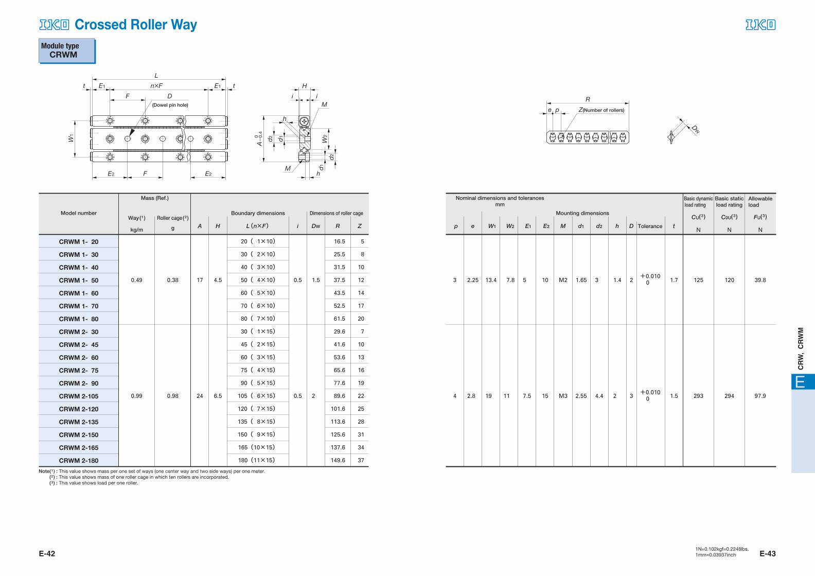
Module type CRWM
Model number
A H L(n×F) i DW R Z
Dimensions of roller cage
CRWM 1- 20
CRWM 1- 30
CRWM 1- 40
CRWM 1- 50
CRWM 1- 60
CRWM 1- 70
CRWM 1- 80
CRWM 2- 30
CRWM 2- 45
CRWM 2- 60
CRWM 2- 75
CRWM 2- 90
CRWM 2-105
CRWM 2-120
CRWM 2-135
CRWM 2-150
CRWM 2-165
CRWM 2-180
20( 1×10)�
30( 2×10)�
40( 3×10)�
50( 4×10)�
60( 5×10)�
70( 6×10)�
80( 7×10)�
30( 1×15)�
45( 2×15)�
60( 3×15)�
75( 4×15)�
90( 5×15)�
105( 6×15)�
120( 7×15)�
135( 8×15)�
150( 9×15)�
165(10×15)�
180(11×15)�
16.5
25.5
31.5
37.5
43.5
52.5
61.5
29.6
41.6
53.6
65.6
77.6
89.6
101.6
113.6
125.6
137.6
149.6
5
8
10
12
14
17
20
7
10
13
16
19
22
25
28
31
34
37
Note( 1 ) : This value shows mass per one set of ways (one center way and two side ways) per one meter.
( 2 ) : This value shows mass of one roller cage in which ten rollers are incorporated.
( 3 ) : This value shows load per one roller.
0.49
0.99
0.38
0.98
17
24
4.5
6.5
1.5
2
0.5
0.5
Boundary dimensions Mounting dimensions
Tolerancep e W1 W2 E1 E2 M d1 d2 h D
3
4.4
1.4
2
t
1.7
1.5
2
3
125
293
120
294
39.8
97.9
1.65
2.55
M2
M3
10
15
5
7.5
7.8
11
13.4
19
2.25
2.8
3
4
+0.0100
+0.0100
F
W1
n×F E1E1t t
L
D(Dowel pin hole)
E2E2 F
H
iM
i
h
Mh
d2
d2 d1
d1
W2
A
0-
0.4
R
pe Z(Number of rollers)
DW
Mass (Ref.)
Way( 1
)
kg/m
Roller cage( 2
)
g
Nominal dimensions and tolerancesmm
CU( 3 )�N
C0U( 3 )�N
FU( 3 )�N
Allowable load
Basic dynamic load rating
Basic static load rating
E-42 E-431N=0.102kgf=0.2248lbs.1mm=0.03937inch
Crossed Roller Way
465-511 05.2.25 11:01 AM ページ E-42

E
CR
W,
CR
WM
Module type CRWM
Mounting dimensions
Tolerancep e W1 W2 E1 E2 M d1 d2 h
6
7.5
3.1
4.1
t
2
2
4
5
638
1 230
609
1 180
203
392
3.3
4.3
M4
M5
25
40
12.5
20
16.6
20
29
35
3.5
5
5
7
+0.0120 ��������������������
+0.0120
Model number
A H L(n×F) i DW R Z
Dimensions of roller cage
CRWM 3- 50
CRWM 3- 75
CRWM 3-100
CRWM 3-125
CRWM 3-150
CRWM 3-175
CRWM 3-200
CRWM 3-225
CRWM 3-250
CRWM 3-275
CRWM 3-300
CRWM 4- 80
CRWM 4-120
CRWM 4-160
CRWM 4-200
CRWM 4-240
CRWM 4-280
CRWM 4-320
CRWM 4-360
CRWM 4-400
CRWM 4-440
CRWM 4-480
50( 1×25)�
75( 2×25)�
100( 3×25)�
125( 4×25)�
150( 5×25)�
175( 6×25)�
200( 7×25)�
225( 8×25)�
250( 9×25)�
275(10×25)�
300(11×25)�
80( 1×40)�
120( 2×40)�
160( 3×40)�
200( 4×40)�
240( 5×40)�
280( 6×40)�
320( 7×40)�
360( 8×40)�
400( 9×40)�
440(10×40)�
480(11×40)�
42
62
82
102
122
142
162
182
202
222
242
73
101
136
164
199
227
262
297
325
360
388
8
12
16
20
24
28
32
36
40
44
48
10
14
19
23
28
32
37
42
46
51
55
Note( 1 ) : This value shows mass per one set of ways (one center way and two side ways) per one meter.
( 2 ) : This value shows mass of one roller cage in which ten rollers are incorporated.
( 3 ) : This value shows load per one roller.
1.99 2.96 36 8.5 30.5
3.28 6.91 44 11.5 40.5
Boundary dimensions
D
F
W1
n×F E1E1t t
L
D(Dowel pin hole)
E2E2 F
H
iM
i
h
Mh
d2
d2 d1
d1
W2
A
0-
0.4
R
pe Z(Number of rollers)
DW
Mass (Ref.)
Way( 1
)
kg/m
Roller cage( 2
)
g
Nominal dimensions and tolerancesmm
CU( 3 )�N
C0U( 3 )�N
FU( 3 )�N
Allowable load
Basic dynamic load rating
Basic static load rating
E-44 E-451N=0.102kgf=0.2248lbs.1mm=0.03937inch
Crossed Roller Way
465-511 05.2.25 11:01 AM ページ E-44
E
CR
W,
CR
WM
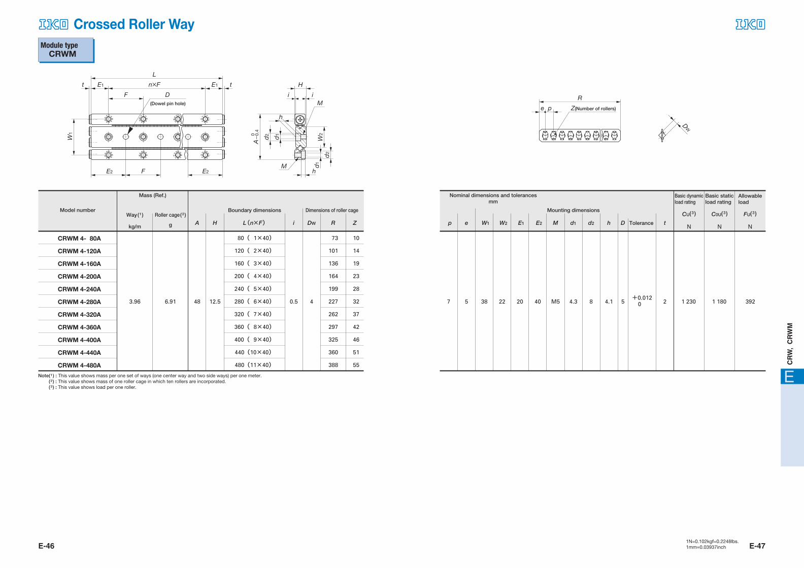
Module type CRWM
Model number
A H L(n×F) i DW R Z
Dimensions of roller cage
CRWM 4- 80A
CRWM 4-120A
CRWM 4-160A
CRWM 4-200A
CRWM 4-240A
CRWM 4-280A
CRWM 4-320A
CRWM 4-360A
CRWM 4-400A
CRWM 4-440A
CRWM 4-480A
80( 1×40)�
120( 2×40)�
160( 3×40)�
200( 4×40)�
240( 5×40)�
280( 6×40)�
320( 7×40)�
360( 8×40)�
400( 9×40)�
440(10×40)�
480(11×40)�
73
101
136
164
199
227
262
297
325
360
388
10
14
19
23
28
32
37
42
46
51
55
Note( 1 ) : This value shows mass per one set of ways (one center way and two side ways) per one meter.
( 2 ) : This value shows mass of one roller cage in which ten rollers are incorporated.
( 3 ) : This value shows load per one roller.
3.96 6.91 48 12.5 40.5
Boundary dimensions Mounting dimensions
Tolerancep e W1 W2 E1 E2 M d1 d2 h D
8 4.1
t
25 1 230 1 180 3924.3M54020223857+0.012
0
F
W1
n×F E1E1t t
L
D(Dowel pin hole)
E2E2 F
H
iM
i
h
Mh
d2
d2 d1
d1
W2
A
0-
0.4
R
pe Z(Number of rollers)
DW
Mass (Ref.)
Way( 1
)
kg/m
Roller cage( 2
)
g
Nominal dimensions and tolerancesmm
CU( 3 )�N
C0U( 3 )�N
FU( 3 )�N
Allowable load
Basic dynamic load rating
Basic staticload rating
E-46 E-471N=0.102kgf=0.2248lbs.1mm=0.03937inch
Crossed Roller Way
465-511 05.2.25 11:01 AM ページ E-46