Embed Size (px)
Citation preview
THINFLOR™ COMPOSITE FLOOR SYSTEM
US Technical and Structural Information
A VERSATILE, HIGH-STRENGTH, LONG-SPAN FLOORING SOLUTION
THINFLOR™ COMPOSITE FLOORING SYSTEM
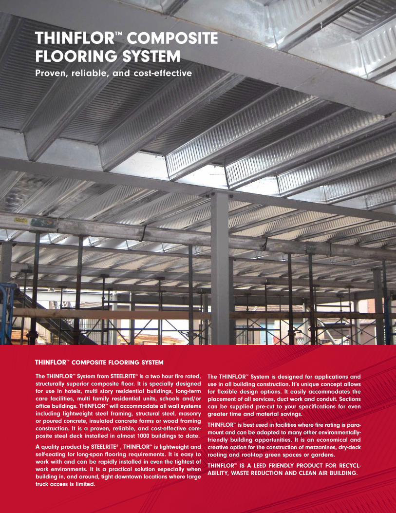
THINFLOR™ COMPOSITEFLOORING SYSTEMProven, reliable, and cost-effective
The THINFLOR™ System from STEELRITE® is a two hour fire rated,structurally superior composite floor. It is specially designedfor use in hotels, multi story residential buildings, long-termcare facilities, multi family residential units, schools and/oroffice buildings. THINFLOR™ will accommodate all wall systemsincluding lightweight steel framing, structural steel, masonryor poured concrete, insulated concrete forms or wood framingconstruction. It is a proven, reliable, and cost-effective com-posite steel deck installed in almost 1000 buildings to date.
A quality product by STEELRITE® , THINFLOR™ is lightweight andself-seating for long-span flooring requirements. It is easy towork with and can be rapidly installed in even the tightest ofwork environments. It is a practical solution especially whenbuilding in, and around, tight downtown locations where largetruck access is limited.
The THINFLOR™ System is designed for applications anduse in all building construction. It’s unique concept allowsfor flexible design options. It easily accommodates theplacement of all services, duct work and conduit. Sectionscan be supplied pre-cut to your specifications for evengreater time and material savings.
THINFLOR™ is best used in facilities where fire rating is para-mount and can be adapted to many other environmentally-friendly building opportunities. It is an economical andcreative option for the construction of mezzanines, dry-deckroofing and roof-top green spaces or gardens.
THINFLOR™ IS A LEED FRIENDLY PRODUCT FOR RECYCL-ABILITY, WASTE REDUCTION AND CLEAN AIR BUILDING.
TABL E OF CONTENT S
3
ww
w.s
tee
lrit
e.c
om
Introduction .............................................................................................................................................................................................. 2
Benefits ...................................................................................................................................................................................................... 4
Design Criteria and Technical Data .................................................................................................................................................. 5
Steel Deck Cross Section Properties ................................................................................................................................................ 5
Reference Documents ............................................................................................................................................................................ 6
Live Load Calculations.......................................................................................................................................................................... 7
Deflection Due to Slab Weight .......................................................................................................................................................... 7
Specifications .......................................................................................................................................................................................... 8
SI - Metric to Imperial Conversions .................................................................................................................................................... 9
Construction and Installation Guidelines ...................................................................................................................................... 10
Dry Deck .................................................................................................................................................................................................. 12
Examples of Construction Applications .......................................................................................................................................... 14
Fire Ratings and Sound Rating ........................................................................................................................................................ 21
Concrete Volume Values for Estimating ........................................................................................................................................ 21
Reinforcing Bar Information .............................................................................................................................................................. 21
Round Service Hole Details .............................................................................................................................................................. 22
Maximum Round Service Hole Diameters .................................................................................................................................... 22
Steel Deck and Accessories .............................................................................................................................................................. 23
Composite Slab Load Tables - US, Imperial Units...................................................................................................................... 24
0.036 in Deck - #3 to #9 Nominal Rebar........................................................................................................................................ 24
0.048 in Deck - #3 to #9 Nominal Rebar........................................................................................................................................ 31
0.0566 in Deck - #3 to #9 Nominal Rebar ...................................................................................................................................... 38
Composite Slab Load Tables - US, SI Metric Units ......................................................................................................................45
0.914 mm Deck - #3 to #9 Nominal Rebar ...................................................................................................................................... 45
1.22 mm Deck - #3 to #9 Nominal Rebar ...................................................................................................................................... 52
1.44 mm Deck - #3 to #9 Nominal Rebar ...................................................................................................................................... 59
4
ww
w.s
tee
lrit
e.c
om
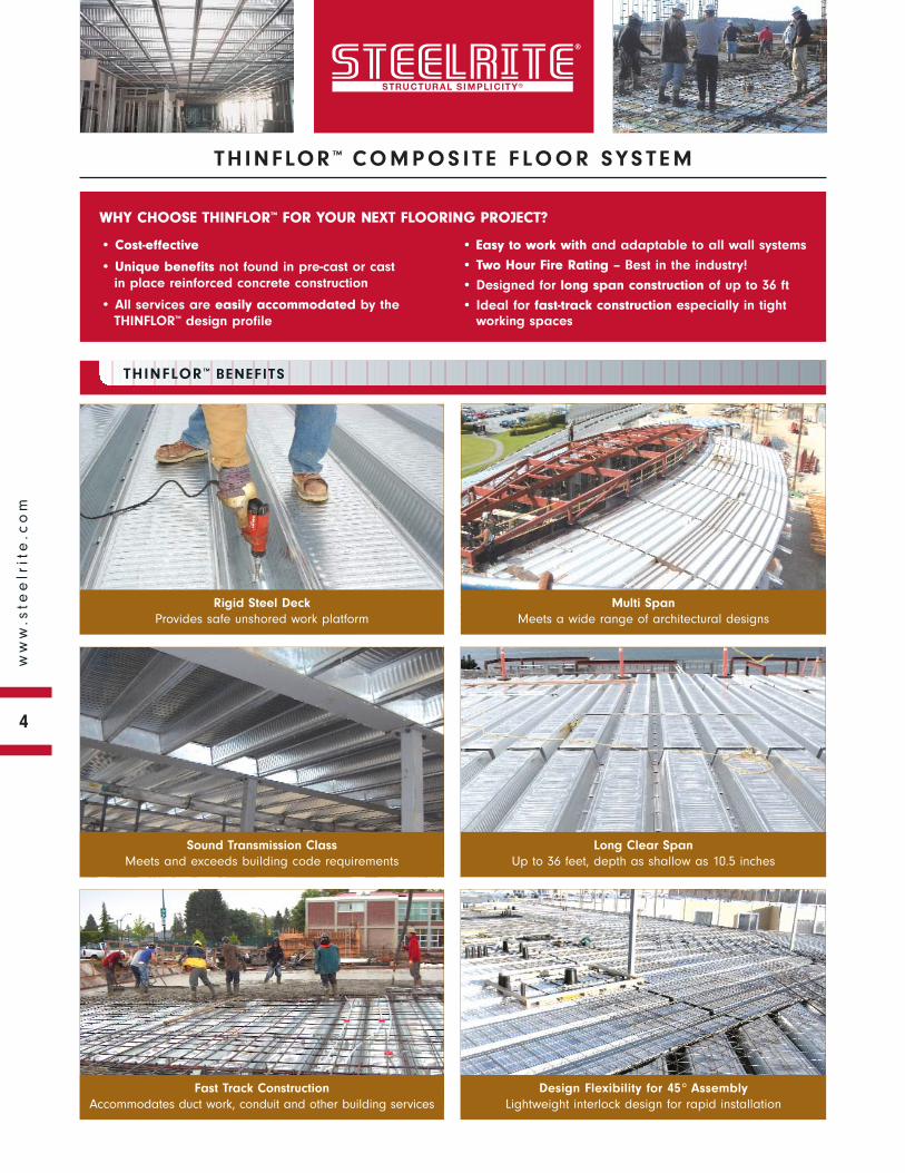
WHY CHOOSE THINFLOR™ FOR YOUR NEXT FLOORING PROJECT?
THINFLOR ™ CO M P O S I T E F LO O R SYS T E M
• Cost-effective
• Unique benefits not found in pre-cast or cast in place reinforced concrete construction
• All services are easily accommodated by the THINFLOR™ design profile
• Easy to work with and adaptable to all wall systems
• Two Hour Fire Rating – Best in the industry!
• Designed for long span construction of up to 36 ft
• Ideal for fast-track construction especially in tight working spaces
Rigid Steel DeckProvides safe unshored work platform
THINFLOR™ BENEFITS
Multi SpanMeets a wide range of architectural designs
Sound Transmission ClassMeets and exceeds building code requirements
Long Clear SpanUp to 36 feet, depth as shallow as 10.5 inches
Fast Track Construction Accommodates duct work, conduit and other building services
Design Flexibility for 45° AssemblyLightweight interlock design for rapid installation
CL
2.20 (in.) 3.65 (in.)
LC
72.5º
16.70 (in.) 7.30 (in.)7.30 (in.)
WasherSide-lap
8.00 (in.)
24.00 (in.)
Cover width 610 mm
185 mm 425 mm
203 mm
56 mm 92.5 mm
185 mm
DES IGN CR I T ER IA AND T ECHN IC AL DATA
5
ww
w.s
tee
lrit
e.c
om
This catalogue provides technical and structural information for the THINFLOR™ composite concrete slab system. All calculations,whenever applicable, were based on CSA Standard S136 and CSSBI documents. Design load tables are also presented, as wellas various construction applications to assist the designer in detailing common structural assemblies. Additional assistance regardingthe THINFLOR™ Composite Flooring System construction method may be obtained by contacting the SteelRite® sales office.
The structural load tables and technical information contained in this catalogue were prepared by Dr. R.M. Schuster, P.Eng.,Professor Emeritus of Structural Engineering at the University of Waterloo.
TABLE NOTES1 Ag = Gross cross sectional area of profile per unit width.2 Ae = Effective cross sectional area of profile per unit width.
3 Sp = Effective section modulus of profile per unit width for positive bending.4 Ix = Effective moment of inertia of profile per unit width.
0.0360 8.00 2.46 0.698 0.281 0.615 3.35
Ix4
(in.4/ft)
0.0480 8.00 3.26 0.931 0.424 0.994 5.42
Base SteelThickness
(in.)
Profile Depth(in.)
Profile Weight(psf)
Ag1
(in.2/ft)
Ae2
(in.2/ft)
Sp3
(in.3/ft)
IMPERIAL UNITS
THINFLOR™ CROSS SECTION PROPERTIES
0.0566 8.00 3.89 1.11 0.543 1.79 7.58
0.914 203 12.0 1477 591 33.0 4.56
Ix4
106mm4/m
1.22 203 15.9 1969 893 53.3 7.38
Base Steel Thickness
mm
Profile Depthmm
Profile Masskg/m2
Ag1
mm2/m
Ae2
mm2/m
Sp3
103mm3/m
SI - UNITS
1.44 203 18.7 2322 1148 92.2 9.57
MATERIALS
• Steel deck meets the requirements of ASTM A6531 Standard Specification of Steel Sheet, Zinc-coated (Galvanized) by the Hot-dip Process, Structural (Physical) Quality. Guaranteed minimumyield strength is 50 ksi (345 MPa) with a minimum zinc coatingmass of G90 (Z275) total both sides. Steel deck base thickness iseither 0.036 in. (0.914 mm), 0.048 in. (1.22 mm) or 0.0566 in.(1.44 mm).
• Reinforcing steel meets the requirements of ASTM A6152. Guaran-teed minimum yield strength is 60.0 ksi (413 MPa). The cleardistance of each reinforcing bar from the bottom of the steel deck is 1.57 in. (40 mm).
• Concrete is assumed to have a minimum cylinder strength of4.00 ksi (27.6 MPa) with a maximum aggregate size of 0.75 in.(20 mm). Normal density structural concrete is 150 lb/ft3
(2400 kg/m3)
STRENGTH DESIGN
Ultimate strength design principles were used in the development of the structural load tables, i.e., the factored strength underconsideration, Ru must be equal to or less than the design strength,φRn, [Ru < φRn]. This is in accordance with ANSI/ASCE 3-913. Sincethe self weight of the steel deck and the concrete have alreadybeen included in the structural load tables, the maximum specifiedload (from the appropriate structural table) shall be:
< (LL + 1.2/1.6DL), where
LL - Specified live loadDL - Specified superimposed dead load1.25 - Dead load factor1.5 - Live load factor
SERVICEABILITY CONSIDERATION
If deflection controls, the maximum specified load (from theappropriate structural table) shall be: ≥ (DL + LL).
SECTION PROPERTIES OF STEEL DECK
Whenever applicable, all structural section properties of the steeldeck were calculated in accordance with AISI S100-20074. Seepage 5 for section properties and cross section details.
STRUCTURAL LOAD TABLES
The structural load tables provide maximum specified loads andwere established in accordance with ANSI/ASCE 3-913.
• SHORING DURING CONSTRUCTION
Shoring requirements for the steel deck during constructionwere established in accordance with ANSI/ASCE 3-913. Thefollowing strength and deflection criteria were used:
Strength – Calculations were based on the combined loads due to the wet concrete, steel deck and construction live loads. Theminimum construction live loads applied separately are:1) 20 psf (1 kPa) uniform load.
2) 150 lb/ft (2.2 kN/m) transverse line load at the centre of the span.
Serviceability – Calculated deflections were based on theuniform load of concrete slab and steel deck and the maximumdeflections were limited to L/180 or 0.75 in. (20 mm).
• LOAD TABLES – Both strength and deflection criteria wereconsidered in accordance with ANSI/ASCE 3-913, as follows:
Strength – Flexure was the only criteria considered in thecalculations since shear-bond is not a mode of failure.
Serviceability – Calculated deflections were based on auniform load with the maximum deflection limited to (L/360).The modular ratio for normal density concrete was taken as 10.See example on page 7 for use of deflection parameter.
Use of Load Tables – See example on page 7 for use of structuralload tables.
STRUCTURAL TESTING
Structural THINFLOR™ composite slab tests were carried out at theUniversity of Salford, England by Prof. D. O’Leary (April, 1993).Based on these tests, shear-bond was not a mode of failure.
REFERENCE DOCUMENTS1 ASTM A653/A653M-09a, “Standard Specification for Steel Sheet and Strip,
Zinc-Coated (Galvanized) or Zinc-Iron Alloy-Coated (Galvannealed) by the
Hot-Dip Process“, 100 Barr Harbor Drive, West Conshohocken, Pennsylvania
19428-2959;
2 ASTM A615/A615M-09b “Standard Specification for Deformed and Plain
Carbon-Steel Bars for Concrete Reinforcement”, 100 Barr Harbor Drive, West
Conshohocken, Pennsylvania 19428-2959;
3 ANSI/ASCE 3-91, “Standard for the Structural Design of Composite Slabs“,
American Society of Civil Engineers (ASCE), 1801 Alexander Bell Drive, Reston,
VA 20191;
4 AISI S100-2007, “North American Specification for the Design of Cold-
Formed Steel Structural Members”, American Iron and Steel Institute (AISI),
1140 Connecticut Avenue, NW, Washington, DC 20036;
5 ANSI/ASCE 9-91, "Standard for Construction and Inspection of Composite
Slabs", American Society of Civil Engineers (ASCE), 1801 Alexander Bell Drive,
Reston, VA 20191;
6 Warnock, A.C.C “Factors Affecting Sound Transmission Loss”, Canadian Building
Digest No. 239, National Research Council of Canada, Ottawa, July 1985.
7 “List of Equipment and Materials, Volume II, Building Materials”, Underwriters’
Laboratories of Canada, Scarborough, Ontario Canada, 1998.
8 Fire Resistance Directory, Volume 1, 1999”, Underwriters Laboratories Inc.,
Northbrook, Illinois.
DES IGN CR I T ER IA AND T ECHN IC AL DATA
6
ww
w.s
tee
lrit
e.c
om
DESIGN CRITERIA
DES IGN CR I T ER IA AND T ECHN IC AL DATA
7
ww
w.s
tee
lrit
e.c
om
Given the following information, check the adequacy of the THINFLOR™ slab system:
Given:Steel deck - Design thickness = 0.036 in.; yield strength = 50 ksiReinforcing steel - Bar number = 8; yield strength = 60 ksiConcrete - Normal density = 150 lb/ft3
Overall slab depth = 10.5 in.Single span length = 24 ft
Specified Loads
Superimposed dead loada) floor finish = 8.5 psfb) partitions = 14.5 psf
DL = 23.0 psf Live load LL = 100 psf
Total load = {1.2/1.6(DL) + LL} = {0.75(23.0) + 100} = 117psf
Use of load table:
From the appropriate table (page 29), the maximum specified load is 133 psf, which is controlled by deflection and is checked as follows.
(DL + LL) = (23.0 + 100) = 123 psf
Since 123 > 133 OK
Where:
wd = Maximum specified deflection load in psf or kPa,SLDP = Deflection parameter from load table,DC = Deflection constant such as 360,L = Span length in feet or meter
Examples:
Base steel thickness – 0.036 in. Base steel thickness – 0.914 mmBar number – 8 Bar number – 8 Slab depth – 10.5 in. Slab depth – 260 mmSpan length, L, – 25 ft Span length, L, – 8 mFrom table on page 29, SLDP = 662 From table on page 50, SLDP = 840 Assume DC = 360 Assume DC = 480
SI Metric UnitsImperial Units
wd =SLDP x 103
DC x (L)3wd =
SLDP x 106
DC x (L)3
wd =662 x 106
360 x (24)3= 133 psf wd =
840 x 103
480 x (8)3= 3.42 kPa
NOTE: For confirmation of values, see appropriate load tables.
NOTE: One shore support is required at mid-span since the maximum unshored span is 13.3 ft.
THINFLOR™ EXAMPLE ( IMPERIAL UNITS)
USE OF DEFLECTION PARAMETER
DEFLECTION DUE TO SLAB WEIGHT
The deflection due to the slab weightcan be calculated as follows. Thecalculation is based on the uncrackedmoment of inertia of the section andthe deflection parameter, SWDP, canbe obtained from the load tables.
SI-Units
Imperial Units
δsw =SWDP x (L)4
103= mm
δsw =SWDP x (L)4
106= in.
L = metres
L = feet
For DC = 360, wd = 4.56 kPa (Table)
8
ww
w.s
tee
lrit
e.c
om
THINFLOR ™ SPECIF ICAT IONS
1.1 SCOPE
These Specifications cover the design, manufacture and use of theTHINFLOR™ composite slab system.
• Furnish all materials and services for the fabrication of theTHINFLOR™ composite floor system in accordance with theseSpecifications and applicable drawings. THINFLOR™ compositeslab panels/systems shall be manufactured and marketed byBAILEY / STEELRITE®.
• Fully co-ordinate the THINFLOR™ composite floor system withstructural, mechanical, electrical and architectural componentsof the building.
1.2 CODE & STANDARD
• Design and manufacturing shall be in strict accordance with theTHINFLOR™ composite floor systems, BAILEY / STEELRITE®, usingsteel conforming to the requirements of of ASTM A6531, StandardSpecification for Steel Sheet, Zinc-coated (Galvanized) by the HotDip Process and Having Structural Physical Quality. Guaranteedminimum yield strength shall be 50 ksi (345 MPa) with aminimum zinc coating mass of G90 (Z275) total including bothsides. Steel deck base thickness is either 0.036 in. (0.914 mm),0.048 in. (1.22 mm) or 0.0566 in. (1.44 mm).
• Reinforcing steel shall meet the requirements of ASTM A6152
Guaranteed minimum yield strength shall be 60 ksi (345 MPa).The clear distance of each reinforcing bar from the bottom of thesteel deck shall be 1.6 in. (40 mm).
• Concrete shall have a minimum cylinder strength of 4.0 ksi (27.6MPa) with a maximum aggregate size of 0.75 in. (20 mm).Normal density structural concrete used shall be 150 lb/ft3
(2400 kg/m3).
1.3 DESIGN
• Strength – Flexural design shall be by ultimate strength principleswhich were used in the development of the structural load tables:
• The factored strength under consideration, Ru must be equal toor less than the design strength, φRn [Ru < φRn]. This is inaccordance with ANSI/ASCE 3-913.
• Since the self-weight of the steel deck, the reinforcing bar and theconcrete have been included in the structural load tables, themaximum specified load (from the appropriate structural loadtable) shall be: < (LL + 1.2/1.6DL),
where:LL - Specified live loadDL - Specified superimposed dead load1.2 - Dead load factor1.6 - Live load factor
• Serviceability – If deflection controls, the maximum specifiedload (from the appropriate structural load table) shall be:< (LL + DL).
1.4 SHOP DRAWINGS
• Detailed erection drawings shall be submitted by the purchaserto the Architect, Engineer, General Contractor or representativefor approval, showing material lists, mark numbers, types,locations, spacing of floor pans and accessories showingmethod of attachment to supporting members. Contract drawingnotes relative to the THINFLOR™ composite floor system shall beconsidered a part of this Specification as though fully set forthherein.
• Shop drawings, prepared only from approved erection drawings,shall be used for fabrication and erection.
• Figured dimensions only shall be used. Scaling drawings shall NOT be permitted.
1.5 HANDLING & STORAGE
• Care shall be exercised at all times to avoid damage toTHINFLOR™ composite floor system components during loading,storing and erecting. Damaged decking must be replaced.
• THINFLOR™ deck panels are supplied in bundles of up to 20sheets. Each bundle can weigh up to 3300 lb (1.5 tonnes).Individual decking elements can twist when lifted so care shallbe taken when lifting with slings or forks.
• THINFLOR™ deck panels shall be stored on timber supports,clear of the ground. The bundles are marked and shall bepositioned on and/or in the area indicated on the layoutdrawings. The bundles shall be placed with the pre-punchedholes in the lap on the same side, unless otherwise noted onthe layout drawings.
1.6 PRODUCTS
• THINFLOR™ steel deck panels are fabricated using G90 (Z275)galvanized steel sheet, of either 0.036 in. (0.914 mm), 0.048 in.(1.22 mm) or 0.0566 in. (1.44 mm)
• End Closures are fabricated using G90 (Z275) galvanized steelsheet, 0.060 in. (1.52 mm) in thickness.
• Perimeter Trims are fabricated using G90 (Z275) galvanizedsteel sheet, 0.060 in. (1.52 mm) in thickness.
• Inside Trims are fabricated using G60 (Z180) galvanized steelsheet of either 0.036 in. (0.914 mm) or 0.048 in. (1.22 mm) inthickness, depending on the ThinFlor™ steel deck thickness.
• Corridor Trims are fabricated using G60 (Z180) galvanized steelsheet, 0.060 in. (1.52 mm) in thickness.
• Side-lap Washers are fabricated using G60 (Z180) galvanizedsteel sheet, 11..2222 mmmm 0.048 in. (1.22 mm) in thickness.
• Rebar Supports are fabricated using G60 (Z180) galvanizedsteel sheet, 0.036 in. (0.914 mm) in thickness.
• Restraint Straps are fabricated using G60 (Z180) galvanizedsteel sheet, 0.036 in. (0.914 mm) in thickness.
9
ww
w.s
tee
lrit
e.c
om
THINFLOR ™ SPECIF ICAT IONS
1.7 EXECUTION
• Installation shall be in accordance with the latest Construction
Guidelines for the THINFLOR™ composite floor system. Care shall
be exercised to avoid damage through careless handling during
unloading, storing and erecting. Suitably qualified personnel
shall install THINFLOR™ floor components.
• Ensure that current decking drawings are being used. The
THINFLOR™ deck panels shall be correctly fastened at each end to
the bearing wall substrate with appropriate mechanical fasteners.
• End diaphragm closures shall be fixed to the bearing wall
substrate prior to the decking being installed, using a minimum
of 2 fasteners (such as shot-fired pins or self-drilling fasteners,
and using the following fastener Specifications or equivalency:
In addition to the main structural fastening, the profile top flanges
are fixed to the 2 in. (50 mm) ends of the end diaphragm closures
using self-drilling fasteners at a frequency of 1 fastener per profile.
No. 12 x 1 in. (25 mm) or better, hexagon washer head, zinc
coated or equivalent. The above fasteners shall be installed using
a correctly set screw gun to the data available from the fastener
supplier.
• Perimeter trims shall be fastened to the wall substrate in a true
and plumb manner, using the appropriate fastener to suit the
steel or concrete substrate at 14 in. (350 mm) intervals in
accordance with the data available from the fastener supplier.
• Interior deck panel closures shall be fastened to the THINFLOR™
deck panel with a minimum of 2 in. (50 mm) overlap, fastened
together with No. 12 x 1 in. (25 mm) or better, hexagon washer
head self-drilling screws spaced at 14 in. (350 mm) on centre.
Panel closures shall be the equivalent thickness of the
THINFLOR™ deck panel specified. Alternately, the THINFLOR™
panel can be cut longitudinally and overlapped a minimum of 3 in.
(75 mm) and fastened together at 12 in. (300 mm) on centre
with 2 fasteners paired 1 in. (25.4 mm) apart.
• Side-lap washers shall be installed at 14 in. (350 mm) along the
bottom trough of each vault profile using No. 12 x 1 in. (25 mm)
or better, hexagon washer head self-drilling screws. The fastener
location is indicated by pre-punched holes in the male overlap.
The laps shall be correctly connected together as they form a
critical part of the flooring system.
• Rebar supports shall be installed at 48 in. (1220 mm) on centre
maximum, to support the reinforcing bars as specified in each vault
or trough in accordance with Section 1.2 of these Specifications
– 1.6 in. (40 mm) clearance.
• Restraint straps shall be installed 16 in. (400 mm) on centre, one
end to the perimeter trim return flange and the other end to the
top of the deck panel for concrete pressure restraint during the
concrete placement phase of construction.
• Shoring or propping shall be supplied and installed by qualified
personnel at the locations specified on the drawings. If in doubt,
check with the supplier’s technical department and the engineer
of record. Shoring shall not be removed until the concrete has
reached 75% of its required design strength, or as authorised by
the engineer of record. Consult with the engineer of record to be
sure that the shoring meets the local jurisdictional requirements
before placing of concrete.
• Concrete shall be placed in accordance with ANSI/ASCE 9-915.
Good concrete placement practices shall be carried out at all
times. Refer to concrete practice guidelines before starting
concrete placement.
1.8 SI -METRIC TO IMPERIAL CONVERSIONS
Listed below are some common conversion factors to assist users
with the information contained in this catalogue.
From SI-Metric Units To Imperial Units Divide by
mm in. 25.4mm2 in.2 645.2mm3 in.3 16 387mm4 in.4 416 231m ft 0.3048m2 ft2 0.0929kN kips 4.44822kPa (kN/m2) psf 0.04788kg/m lb/ft 1.488MPa (N/mm2) kips/in.2 6.895N-m kips-in. 113
10
ww
w.s
tee
lrit
e.c
om
CONSTRUCT ION AND INSTALL AT ION GUIDEL INES
THINFLOR™ PANEL DECKING – shall be positively fastened to the supporting structure to avoid movement during construction andexcessive deflection during placement of concrete. The fastening frequency of main fasteners is 1 per trough at each panel end at 610 mm (24 in.) on centre along the support structure. The THINFLOR™ deck panels shall bear a minimum of 50 mm (2 in.) onto thesupport structure. When fastening panels to structural steel work, use heavy-duty shotfired pins or self-drilling fasteners as designed andspecified by the engineer of record. For brick, block and concrete, the decking shall be fastened using adequate masonry fasteners asdesigned and specified by the engineer of record. The bottom flange of the End Closure shall be fastened to the supporting structure with1 fastener per module at 610 mm (24 in.) on centre, or as specified by the engineer of record.
In addition to the main fasteners, the top flanges of the End Closures shall be fastened to the decking, one fastener per module, eithercentred or 610 mm (24 in.) on centre. Side-lap Washers shall be fastened at 350 mm (13.8 in.) centres along the bottom trough, using No. 14 1/4 - 14 x 1 self-drilling fasteners or better. The location of the fasteners is prepunched on the male trough flange, which overlapsthe female trough flange.
NOTE 1: Every side-lap fastener shall include a Side-lap Washer. This washer is required to properly attach the individual steel deckpanels together.
NOTE 2: When a suspended ceiling is used, the minimum thread length of the fastener is 25 mm (1 in.).
NOTE 3: THINFLOR™ decking can be end cantilevered as shown in the “Examples of Construction Applications” section on page 14.When side cantilevers are required, stub beams or brackets shall be provided by the structural steel fabricator, as designed by theengineer of record. Cantilevers shall also be assessed for reinforcement by the engineer of record.
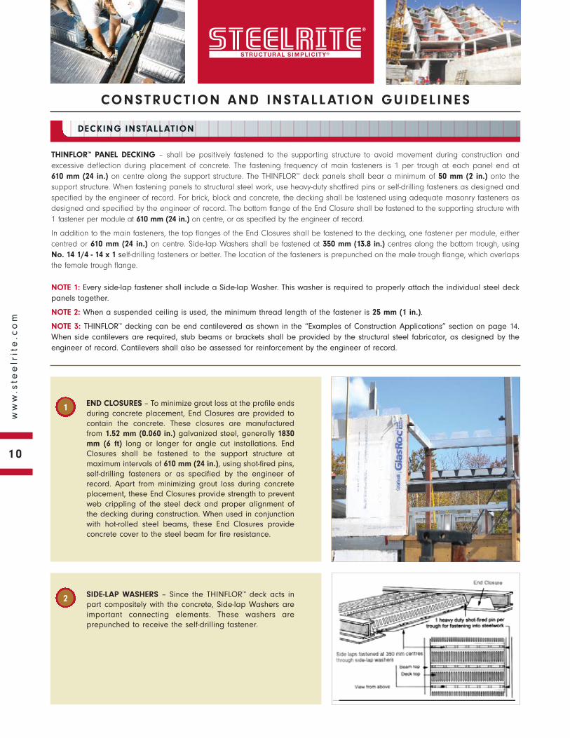
END CLOSURES – To minimize grout loss at the profile endsduring concrete placement, End Closures are provided tocontain the concrete. These closures are manufacturedfrom 1.52 mm (0.060 in.) galvanized steel, generally 1830mm (6 ft) long or longer for angle cut installations. EndClosures shall be fastened to the support structure atmaximum intervals of 610 mm (24 in.), using shot-fired pins,self-drilling fasteners or as specified by the engineer ofrecord. Apart from minimizing grout loss during concreteplacement, these End Closures provide strength to preventweb crippling of the steel deck and proper alignment ofthe decking during construction. When used in conjunctionwith hot-rolled steel beams, these End Closures provideconcrete cover to the steel beam for fire resistance.
SIDE-LAP WASHERS – Since the THINFLOR™ deck acts inpart compositely with the concrete, Side-lap Washers areimportant connecting elements. These washers areprepunched to receive the self-drilling fastener.
DECKING INSTALLATION
1
2

11
ww
w.s
tee
lrit
e.c
om
CONSTRUCT ION AND INSTALL AT ION GUIDEL INES
DECKING INSTALLATION
PERIMETER TRIMS – Are required for the retention of wet concrete to the correct levelat the decked floor perimeters and designed openings. They are supplied in 3 m (10ft) lengths of galvanized steel. Perimeter Trims are usually fastened by shot-fired pinsto the structural steel or by self-drilling fasteners to the support structure at 610 mm (24in.) on centre, or as specified by the engineer of record.
PENETRATIONS – Penetrations through the floor decking shall be cut after the concretehas cured. Before placing concrete, any openings shall be boxed out with form workas specified by the engineer of record. The following guidelines are suggested for isolatedopenings at right angles to the deck span, or as specified by the engineer of record:
• Up to 300 mm (12 in.) square penetrations centred on the top of the profile of thedeck is acceptable without additional reinforcement, other than the minimumshrinkage and temperature mesh.
• Up to 425 mm (16.7 in.) width by 1000 mm (39.4 in.) length opening with additionalreinforcement.
• Openings larger than 425 mm (16.7 in.) require structural steel framing as specifiedby the engineer of record.
• Close grouping of openings transverse to the profile shall be treated as oneopening, requiring additional reinforcement as specified by the engineer of record.
• After the slab has reached 75% of the required concrete compressive strength, anibbler, power saw or coring machine can be used to cut out openings in the topprofile with the approval by the engineer of record.
COLUMNS AND THINFLOR™ DECKING – The steel deck sheeting can be cut and fittedto accommodate various column shapes to minimize grout loss. Where no supportingsteel work is provided, steel angle brackets shall be provided to support the steeldecking, as specified by the engineer of record.
RIB REINFORCEMENT AND MESH PLACEMENT – The THINFLOR™ design requires thatone steel reinforcing bar be placed in each rib profile. The bar size, as shown in theload tables, can vary from 10 mm (0.394 in.) to 35 mm (1.38 in.) in diameter. The barsshall be placed on Rebar Supports which ensure a 40 mm (1.57 in.) spacing from the bottom flange to the underside of the reinforcing bars. Spacing of the RebarSupports shall be in accordance with good practice guidelines, and not exceeding1220 mm (48 in.) on centre. To ensure both vertical and horizontal stability duringconcrete placement, the reinforcing bars shall be tied down periodically through theSide-lap Washers with 1.21 mm (0.0476 in.) diameter tie wiring. It is recommendedthat a minimum standard shrinkage and temperature reinforcing mesh of152x152xMW18.7xMW18.7 (6x6x6/6) be placed above the top of the steel deckingand positioned towards the top of the slab, or as specified by the engineer of record.
RESTRAINT STRAPS – The top of the perimeter edge trim is connected to the deckingwith Restraint Straps at approximately 400 mm (16 in.) on centre using either pop rivetsor self-drilling fasteners. The Restraint Strap can be adjusted to suit the pitch andalignment of the perimeter edge trim.
3
4
5
6
7
12
ww
w.s
tee
lrit
e.c
om
CONSTRUCT ION AND INSTALL AT ION GUIDEL INES
DECKING INSTALLATION
8
9
10
11
12
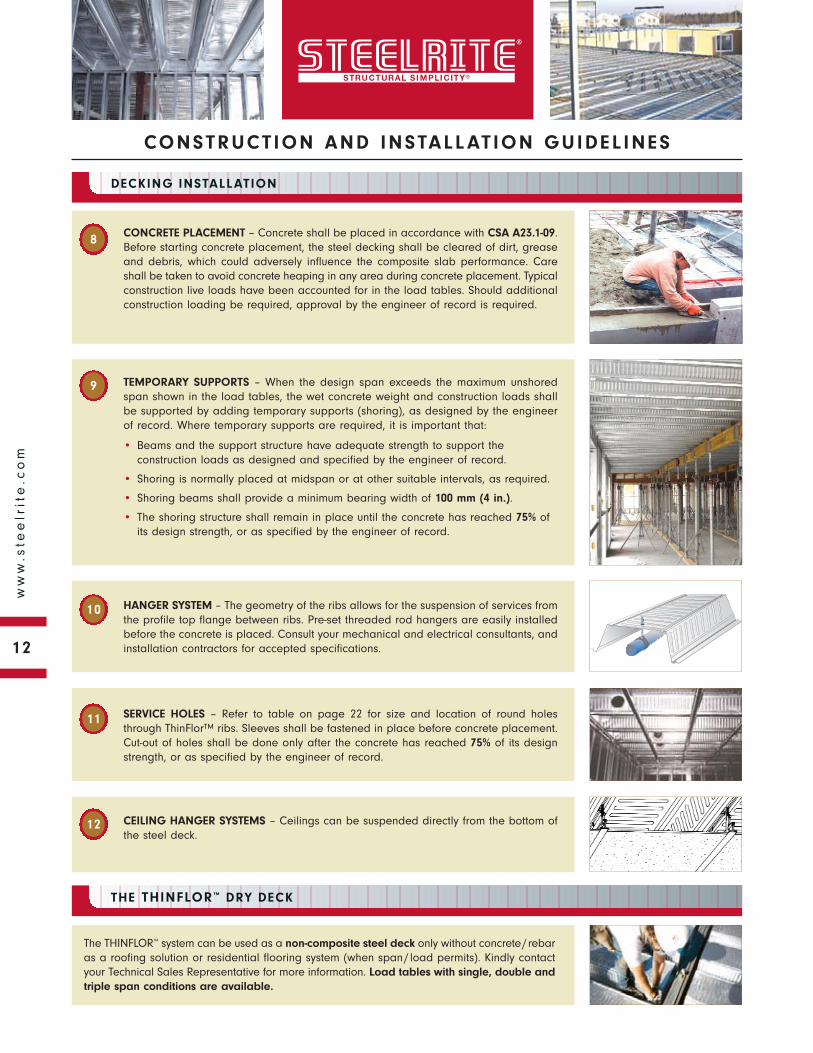
CONCRETE PLACEMENT – Concrete shall be placed in accordance with CSA A23.1-09.Before starting concrete placement, the steel decking shall be cleared of dirt, greaseand debris, which could adversely influence the composite slab performance. Careshall be taken to avoid concrete heaping in any area during concrete placement. Typicalconstruction live loads have been accounted for in the load tables. Should additionalconstruction loading be required, approval by the engineer of record is required.
HANGER SYSTEM – The geometry of the ribs allows for the suspension of services fromthe profile top flange between ribs. Pre-set threaded rod hangers are easily installedbefore the concrete is placed. Consult your mechanical and electrical consultants, andinstallation contractors for accepted specifications.
SERVICE HOLES – Refer to table on page 22 for size and location of round holesthrough ThinFlor™ ribs. Sleeves shall be fastened in place before concrete placement.Cut-out of holes shall be done only after the concrete has reached 75% of its designstrength, or as specified by the engineer of record.
CEILING HANGER SYSTEMS – Ceilings can be suspended directly from the bottom ofthe steel deck.
TEMPORARY SUPPORTS – When the design span exceeds the maximum unshoredspan shown in the load tables, the wet concrete weight and construction loads shallbe supported by adding temporary supports (shoring), as designed by the engineerof record. Where temporary supports are required, it is important that:
• Beams and the support structure have adequate strength to support theconstruction loads as designed and specified by the engineer of record.
• Shoring is normally placed at midspan or at other suitable intervals, as required.
• Shoring beams shall provide a minimum bearing width of 100 mm (4 in.).
• The shoring structure shall remain in place until the concrete has reached 75% ofits design strength, or as specified by the engineer of record.
THE THINFLOR™ DRY DECK
The THINFLOR™ system can be used as a non-composite steel deck only without concrete/rebaras a roofing solution or residential flooring system (when span/load permits). Kindly contactyour Technical Sales Representative for more information. Load tables with single, double andtriple span conditions are available.
13
ww
w.s
tee
lrit
e.c
om
CONSTRUCT ION AND INSTALL AT ION GUIDEL INES
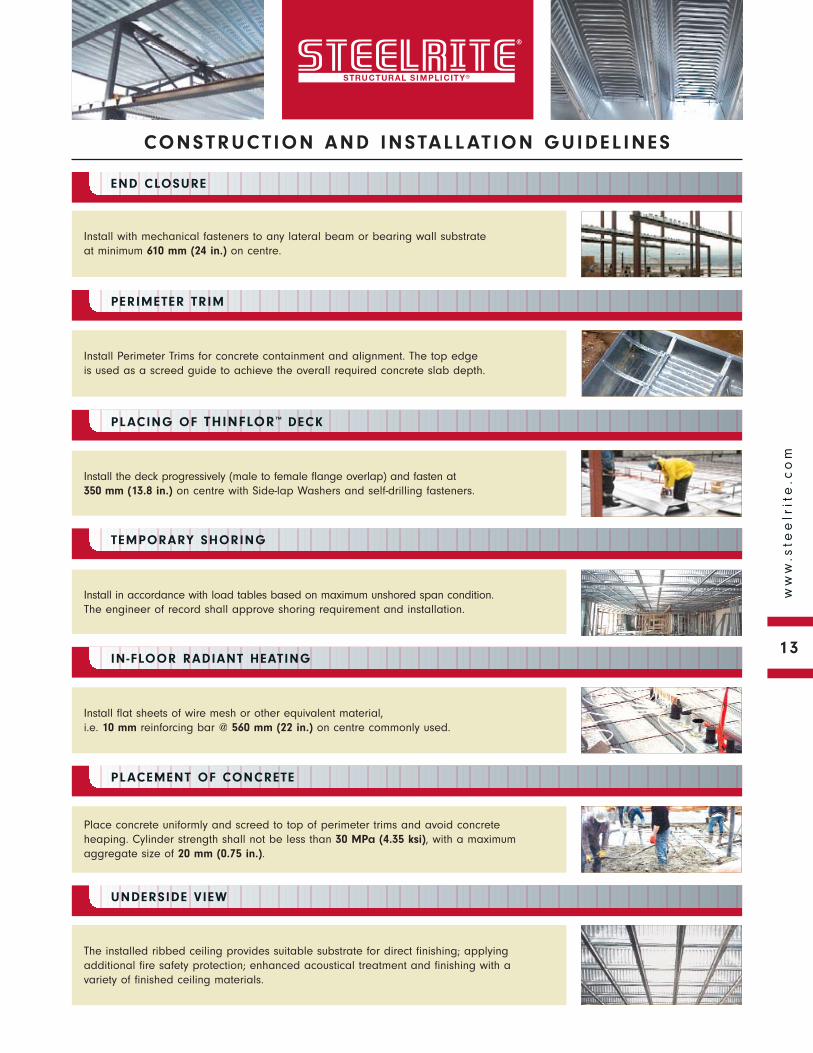
Install with mechanical fasteners to any lateral beam or bearing wall substrate at minimum 610 mm (24 in.) on centre.
END CLOSURE
PERIMETER TRIM
PLACING OF THINFLOR™ DECK
TEMPORARY SHORING
IN-FLOOR RADIANT HEATING
PLACEMENT OF CONCRETE
UNDERSIDE VIEW
Install Perimeter Trims for concrete containment and alignment. The top edge is used as a screed guide to achieve the overall required concrete slab depth.
Install the deck progressively (male to female flange overlap) and fasten at 350 mm (13.8 in.) on centre with Side-lap Washers and self-drilling fasteners.
Install in accordance with load tables based on maximum unshored span condition.The engineer of record shall approve shoring requirement and installation.
Install flat sheets of wire mesh or other equivalent material, i.e. 10 mm reinforcing bar @ 560 mm (22 in.) on centre commonly used.
Place concrete uniformly and screed to top of perimeter trims and avoid concreteheaping. Cylinder strength shall not be less than 30 MPa (4.35 ksi), with a maximumaggregate size of 20 mm (0.75 in.).
The installed ribbed ceiling provides suitable substrate for direct finishing; applyingadditional fire safety protection; enhanced acoustical treatment and finishing with avariety of finished ceiling materials.
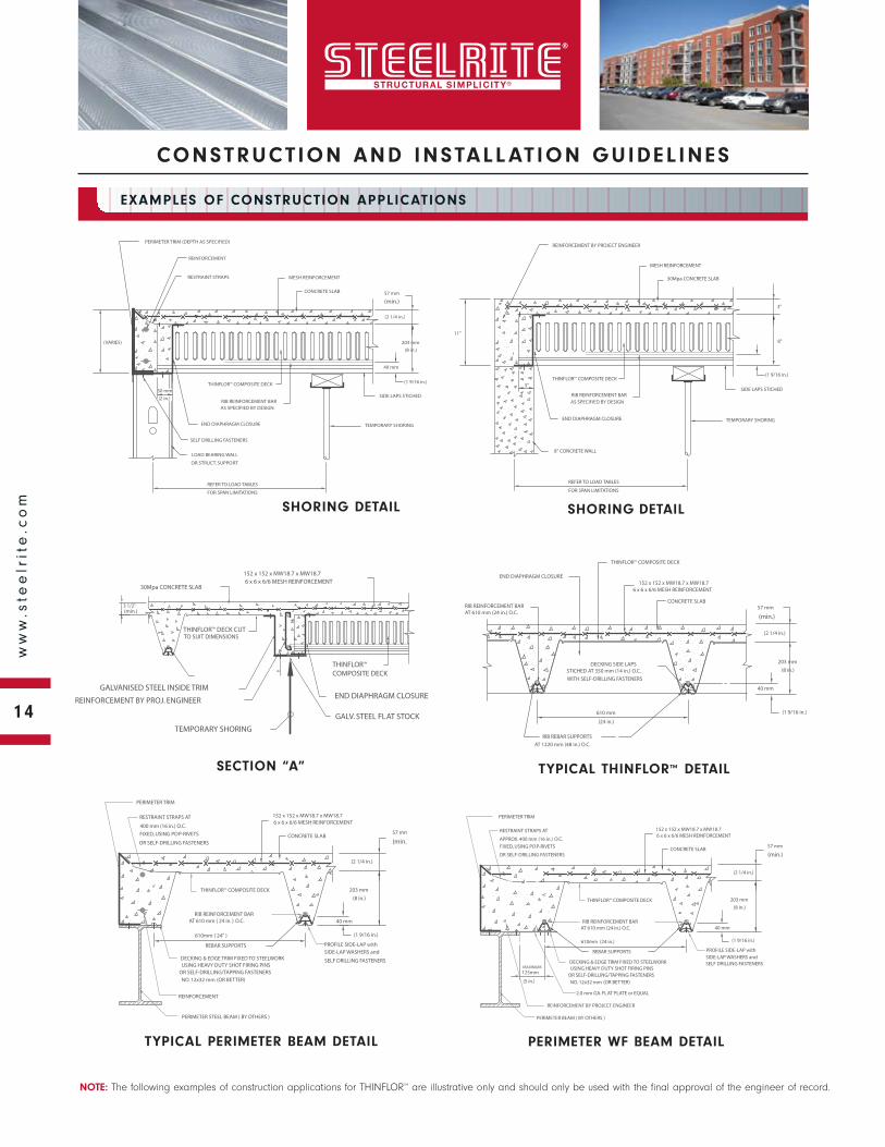
SECTION “A”
TYPICAL PERIMETER BEAM DETAIL
PERIMETER WF BEAM DETAIL
14
ww
w.s
tee
lrit
e.c
om
CONSTRUCT ION AND INSTALL AT ION GUIDEL INES
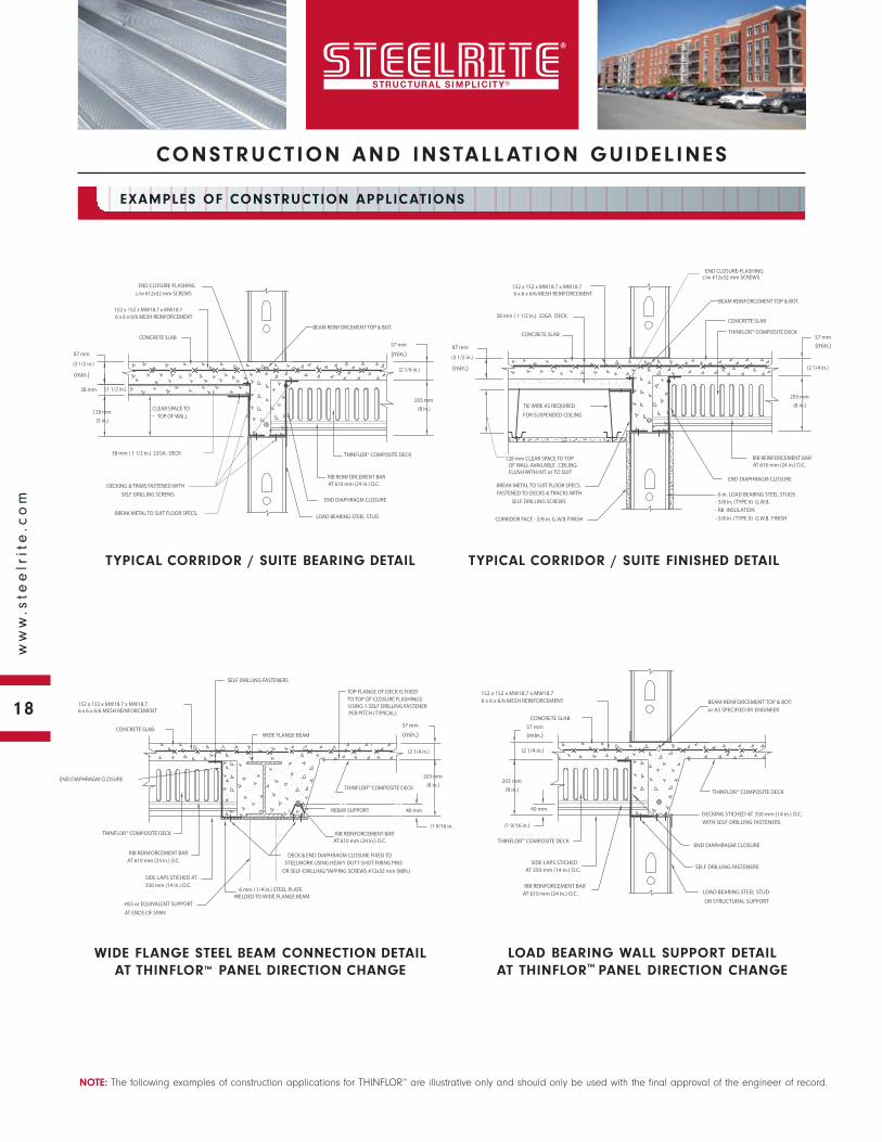
NOTE: The following examples of construction applications for THINFLOR™ are illustrative only and should only be used with the final approval of the engineer of record.
EXAMPLES OF CONSTRUCTION APPLICATIONS
SHORING DETAIL
TYPICAL THINFLOR™ DETAIL
SHORING DETAIL
15
ww
w.s
tee
lrit
e.c
om
CONSTRUCT ION AND INSTALL AT ION GUIDEL INES
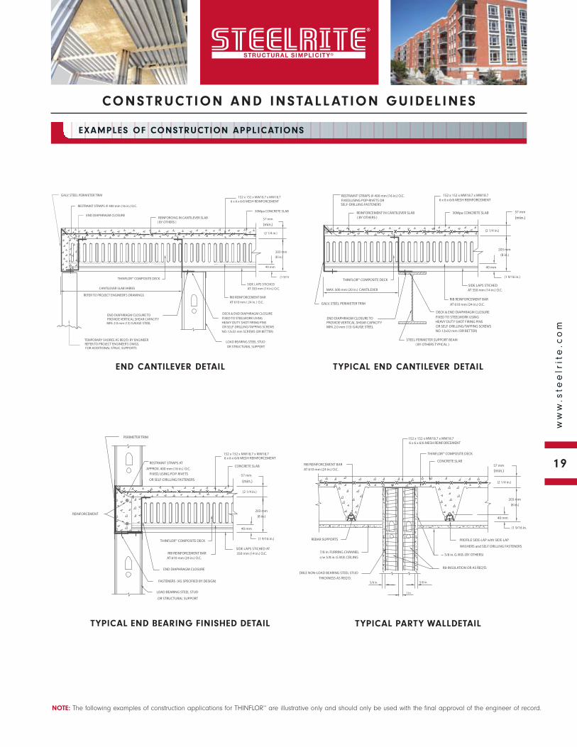
NOTE: The following examples of construction applications for THINFLOR™ are illustrative only and should only be used with the final approval of the engineer of record.
EXAMPLES OF CONSTRUCTION APPLICATIONS
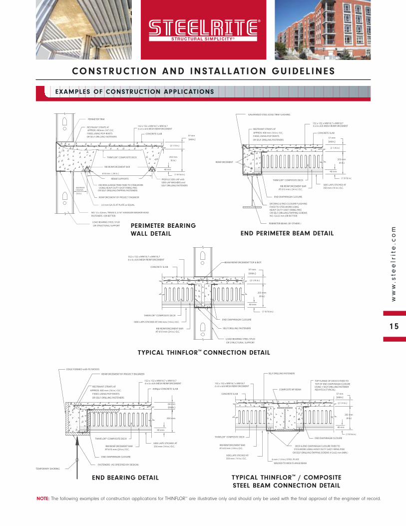
TYPICAL THINFLOR™ / COMPOSITE STEEL BEAM CONNECTION DETAIL
END BEARING DETAIL
TYPICAL THINFLOR™ CONNECTION DETAIL
END PERIMETER BEAM DETAILPERIMETER BEARING WALL DETAIL
16
ww
w.s
tee
lrit
e.c
om
CONSTRUCT ION AND INSTALL AT ION GUIDEL INES
NOTE: The following examples of construction applications for THINFLOR™ are illustrative only and should only be used with the final approval of the engineer of record.
EXAMPLES OF CONSTRUCTION APPLICATIONS
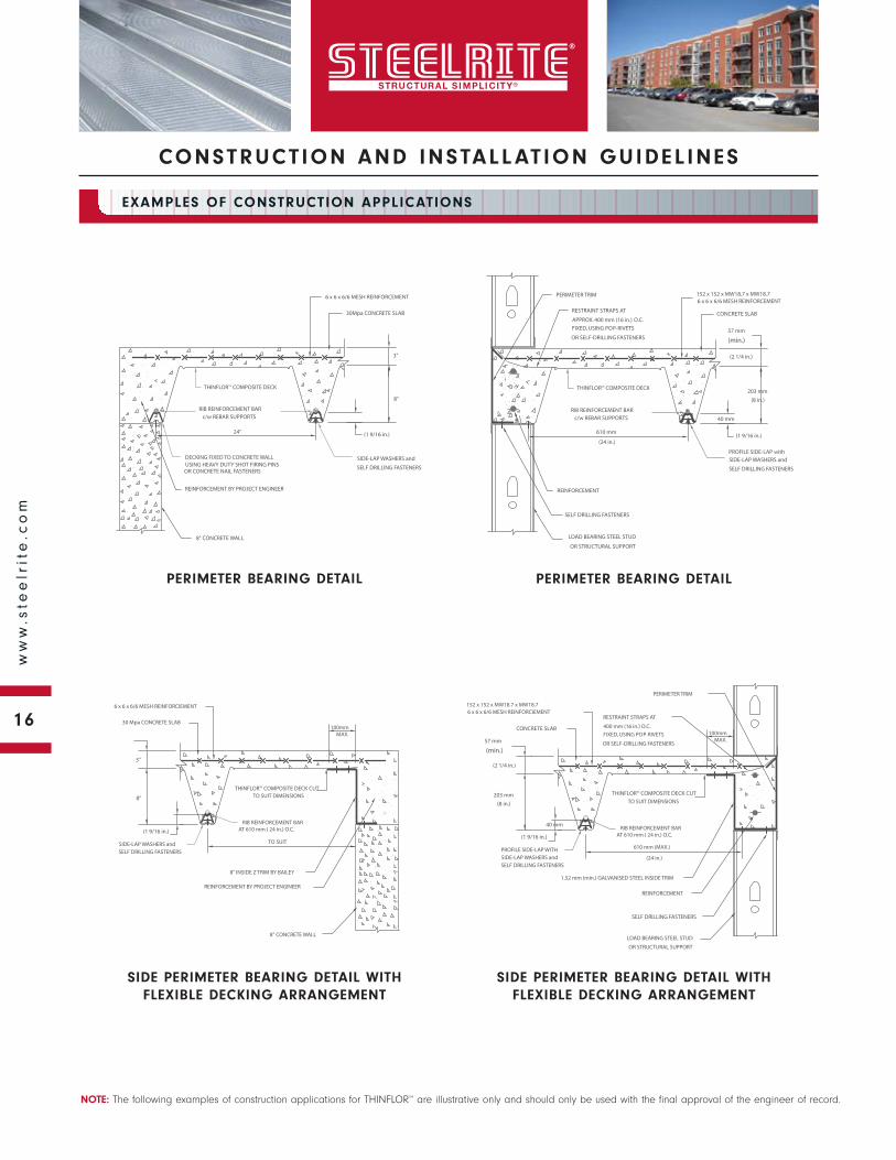
SIDE PERIMETER BEARING DETAIL WITH FLEXIBLE DECKING ARRANGEMENT
SIDE PERIMETER BEARING DETAIL WITH FLEXIBLE DECKING ARRANGEMENT
PERIMETER BEARING DETAIL
PERIMETER BEARING DETAIL
17
ww
w.s
tee
lrit
e.c
om
CONSTRUCT ION AND INSTALL AT ION GUIDEL INES
NOTE: The following examples of construction applications for THINFLOR™ are illustrative only and should only be used with the final approval of the engineer of record.
EXAMPLES OF CONSTRUCTION APPLICATIONS
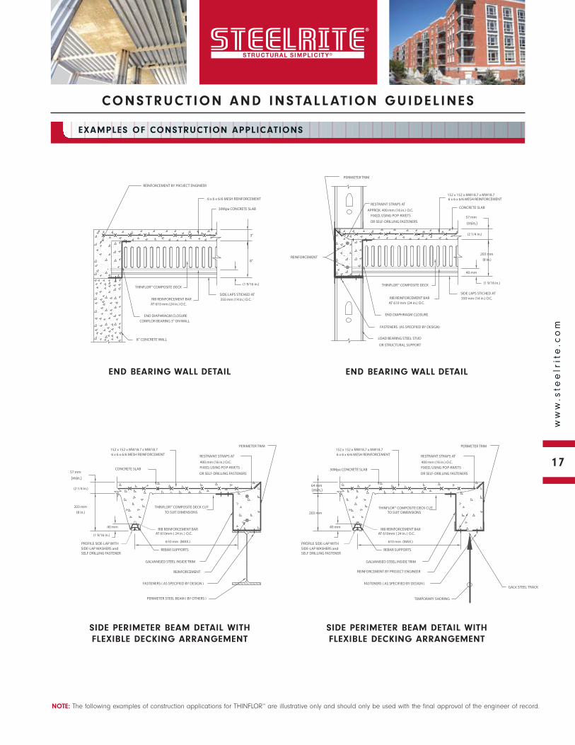
SIDE PERIMETER BEAM DETAIL WITH FLEXIBLE DECKING ARRANGEMENT
SIDE PERIMETER BEAM DETAIL WITH FLEXIBLE DECKING ARRANGEMENT
END BEARING WALL DETAIL
END BEARING WALL DETAIL
18
ww
w.s
tee
lrit
e.c
om
CONSTRUCT ION AND INSTALL AT ION GUIDEL INES
NOTE: The following examples of construction applications for THINFLOR™ are illustrative only and should only be used with the final approval of the engineer of record.
EXAMPLES OF CONSTRUCTION APPLICATIONS
WIDE FLANGE STEEL BEAM CONNECTION DETAIL AT THINFLOR™ PANEL DIRECTION CHANGE
TYPICAL CORRIDOR / SUITE BEARING DETAIL
TYPICAL CORRIDOR / SUITE FINISHED DETAIL
LOAD BEARING WALL SUPPORT DETAIL AT THINFLOR™ PANEL DIRECTION CHANGE
19
ww
w.s
tee
lrit
e.c
om
CONSTRUCT ION AND INSTALL AT ION GUIDEL INES
NOTE: The following examples of construction applications for THINFLOR™ are illustrative only and should only be used with the final approval of the engineer of record.
EXAMPLES OF CONSTRUCTION APPLICATIONS
END CANTILEVER DETAIL
TYPICAL END CANTILEVER DETAIL
TYPICAL END BEARING FINISHED DETAIL TYPICAL PARTY WALLDETAIL
20
ww
w.s
tee
lrit
e.c
om
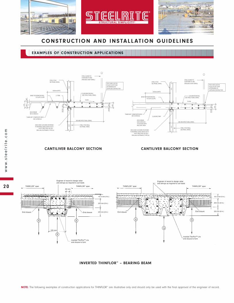
CONSTRUCT ION AND INSTALL AT ION GUIDEL INES
NOTE: The following examples of construction applications for THINFLOR™ are illustrative only and should only be used with the final approval of the engineer of record.
EXAMPLES OF CONSTRUCTION APPLICATIONS
62 mm
125 mm
Engineer of record to design rebar and stirrups as required to suit loads
THINFLOR™ span THINFLOR™ span
End closure
inverted ThinFlor™ c/wend closure to form
End closureEnd closure
inverted ThinFlor™ c/wend closure to form
End closure
S
INVERTED THINFLOR™ – BEARING BEAM
101.5 mm (4 in.)
203 mm (8 in.)
203 mm (8 in.)
101.5 mm (4 in.)
203 mm (8 in.)
203 mm (8 in.)
S
SS
S
S
THINFLOR™ spanTHINFLOR™ span
Engineer of record to design rebar and stirrups as required to suit loads
CANTILIVER BALCONY SECTION CANTILIVER BALCONY SECTION
IMPERIAL UNITS 21
ww
w.s
tee
lrit
e.c
om
THINFLOR ™ DETAILS
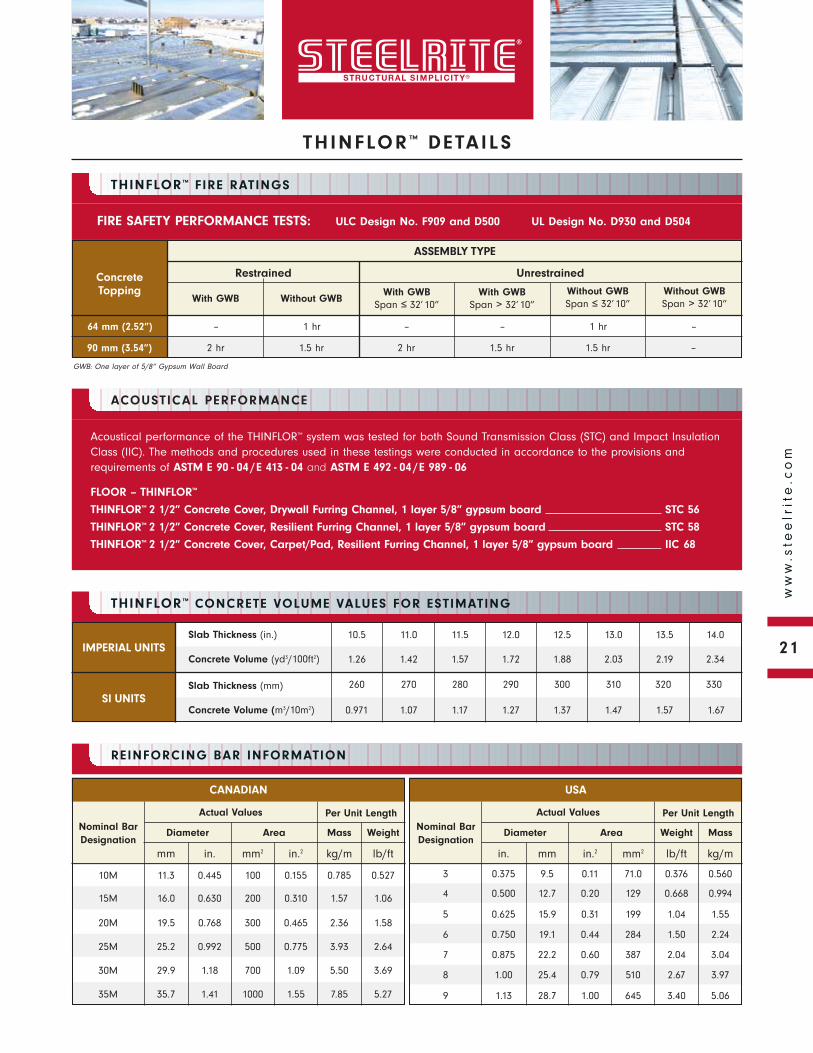
Acoustical performance of the THINFLOR™ system was tested for both Sound Transmission Class (STC) and Impact InsulationClass (IIC). The methods and procedures used in these testings were conducted in accordance to the provisions andrequirements of ASTM E 90 - 04 /E 413 - 04 and ASTM E 492 - 04 /E 989 - 06
FLOOR – THINFLOR™
THINFLOR™ 2 1/2” Concrete Cover, Drywall Furring Channel, 1 layer 5/8” gypsum board STC 56
THINFLOR™ 2 1/2” Concrete Cover, Resilient Furring Channel, 1 layer 5/8” gypsum board STC 58
THINFLOR™ 2 1/2” Concrete Cover, Carpet/Pad, Resilient Furring Channel, 1 layer 5/8” gypsum board IIC 68
THINFLOR™ FIRE RATINGS
REINFORCING BAR INFORMATION
ACOUSTICAL PERFORMANCE
With GWB
ASSEMBLY TYPE
Without GWB
Restrained Unrestrained
With GWBSpan ≤ 32’ 10”
With GWBSpan > 32’ 10”
Without GWBSpan ≤ 32’ 10”
Without GWBSpan > 32’ 10”
FIRE SAFETY PERFORMANCE TESTS: ULC Design No. F909 and D500 UL Design No. D930 and D504
64 mm (2.52”)
90 mm (3.54”)
–
2 hr
1 hr
1.5 hr
–
2 hr
–
1.5 hr
1 hr
1.5 hr
–
–
ConcreteTopping
THINFLOR™ CONCRETE VOLUME VALUES FOR ESTIMATING
SI UNITS
Slab Thickness (in.)
Concrete Volume (yd3/100ft2)
Slab Thickness (mm)
Concrete Volume (m3/10m2)
10.5
1.26
260
0.971
11.0
1.42
270
1.07
11.5
1.57
280
1.17
12.0
1.72
290
1.27
12.5
1.88
300
1.37
13.0
2.03
310
1.47
13.5
2.19
320
1.57
14.0
2.34
330
1.67
GWB: One layer of 5/8” Gypsum Wall Board
Nominal BarDesignation
Per Unit Length
AreaDiameter
in. mm2 in.2mm lb/ftkg/m
0.445 100 0.15511.3 0.5270.78510M
0.630 200 0.31016.0 1.061.5715M
0.768 300 0.46519.5 1.582.3620M
0.992 500 0.77525.2 2.643.9325M
1.18 700 1.0929.9 3.695.5030M
1.41 1000 1.5535.7 5.277.8535M
Actual Values
CANADIAN
Nominal BarDesignation
AreaDiameter
mm in.2 mm2in. kg/mlb/ft
9.5 0.11 71.00.375 0.5600.3763
12.7 0.20 1290.500 0.9940.6684
15.9 0.31 1990.625 1.551.045
19.1 0.44 2840.750 2.241.506
22.2 0.60 3870.875 3.042.047
25.4 0.79 5101.00 3.972.678
Actual Values
USA
28.7 1.00 6451.13 5.063.409
WeightMass
Per Unit Length
MassWeight
260270280290300310320330
135145150160170175185195
125135145150160170175185
120130135145150160170175
110115125130140150155165
100105115120130140145155
85.095.0105110115125130140
22
ww
w.s
tee
lrit
e.c
om
THINFLOR ™ DETAILS
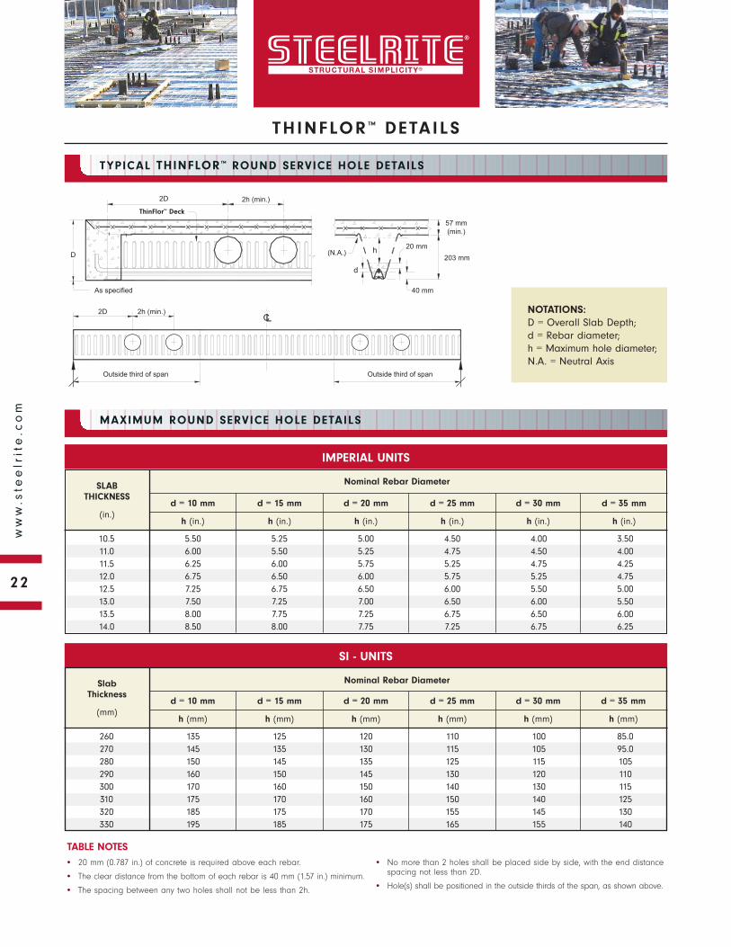
As specified
2D 2h (min.)
h 20 mm
40 mm
(N.A.)
d
203 mmD
57 mm
COMFLOR deck®
(min.)
CL
Outside third of span
2D 2h (min.)
Outside third of span
TYPICAL THINFLOR™ ROUND SERVICE HOLE DETAILS
MAXIMUM ROUND SERVICE HOLE DETAILS
Slab Thickness
(mm)
Nominal Rebar Diameter
d = 15 mm d = 20 mm d = 25 mm d = 30 mmd = 10 mm
h (mm) h (mm) h (mm) h (mm)h (mm)
10.511.011.512.012.513.013.514.0
5.506.006.256.757.257.508.008.50
5.255.506.006.506.757.257.758.00
5.005.255.756.006.507.007.257.75
4.504.755.255.756.006.506.757.25
4.004.504.755.255.506.006.506.75
3.504.004.254.755.005.506.006.25
SLAB THICKNESS
(in.)
Nominal Rebar Diameter
d = 15 mm d = 20 mm d = 25 mm d = 30 mmd = 10 mm
h (in.) h (in.) h (in.) h (in.)h (in.)
IMPERIAL UNITS
SI - UNITS
TABLE NOTES• 20 mm (0.787 in.) of concrete is required above each rebar.
• The clear distance from the bottom of each rebar is 40 mm (1.57 in.) minimum.
• The spacing between any two holes shall not be less than 2h.
• No more than 2 holes shall be placed side by side, with the end distancespacing not less than 2D.
• Hole(s) shall be positioned in the outside thirds of the span, as shown above.
NOTATIONS:D = Overall Slab Depth; d = Rebar diameter; h = Maximum hole diameter; N.A. = Neutral Axis
ThinFlor™ Deck
d = 35 mm
h (in.)
d = 35 mm
h (mm)
23
ww
w.s
tee
lrit
e.c
om
THINFLOR ™ DETAILS
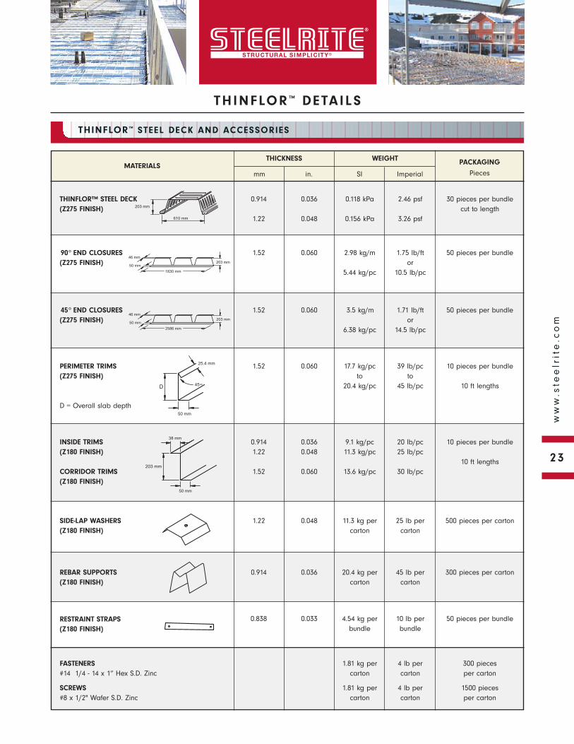
MATERIALS
0.914
1.22
0.036
0.048
0.118 kPa
0.156 kPa
2.46 psf
3.26 psf
WEIGHTTHICKNESS
mm in. SI
PACKAGING
PiecesImperial
THINFLOR™ STEEL DECK(Z275 FINISH)
30 pieces per bundlecut to length
1.52 0.060 2.98 kg/m
5.44 kg/pc
1.75 lb/ftor
10.5 lb/pc
90° END CLOSURES(Z275 FINISH)
50 pieces per bundle
1.52 0.060 17.7 kg/pcto
20.4 kg/pc
39 lb/pcto
45 lb/pc
PERIMETER TRIMS(Z275 FINISH)
D = Overall slab depth
10 pieces per bundle
10 ft lengths
0.9141.22
1.52
0.0360.048
0.060
9.1 kg/pc11.3 kg/pc
13.6 kg/pc
20 lb/pc25 lb/pc
30 lb/pc
INSIDE TRIMS(Z180 FINISH)
CORRIDOR TRIMS(Z180 FINISH)
10 pieces per bundle
10 ft lengths
1.22 0.048 11.3 kg percarton
25 lb percarton
SIDE-LAP WASHERS(Z180 FINISH)
500 pieces per carton
0.914 0.036 20.4 kg percarton
45 lb percarton
REBAR SUPPORTS(Z180 FINISH)
300 pieces per carton
0.838 0.033 4.54 kg perbundle
10 lb perbundle
RESTRAINT STRAPS(Z180 FINISH)
50 pieces per bundle
1.81 kg per carton
1.81 kg per carton
4 lb per carton
4 lb per carton
FASTENERS#14 1/4 - 14 x 1” Hex S.D. Zinc
SCREWS#8 x 1/2" Wafer S.D. Zinc
300 pieces per carton
1500 pieces per carton
203 mm
610 mm
46 mm
50 mm
1830 mm
203 mm
46 mm
50 mm
2586 mm
203 mm
50 mm
38 mm
203 mm
50 mm
25.4 mm
D 45∞
THINFLOR™ STEEL DECK AND ACCESSORIES
1.52 0.060 3.5 kg/m
6.38 kg/pc
1.71 lb/ftor
14.5 lb/pc
45° END CLOSURES(Z275 FINISH)
50 pieces per bundle
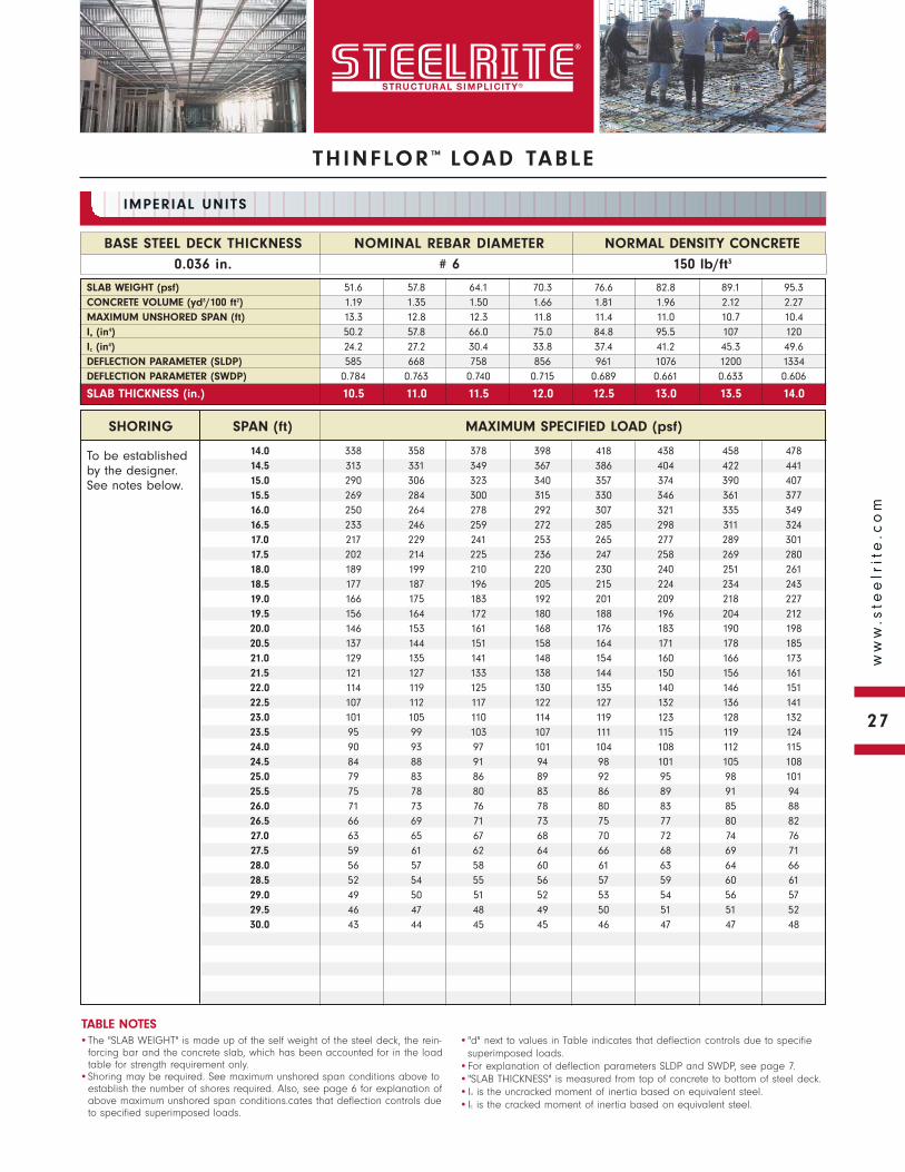
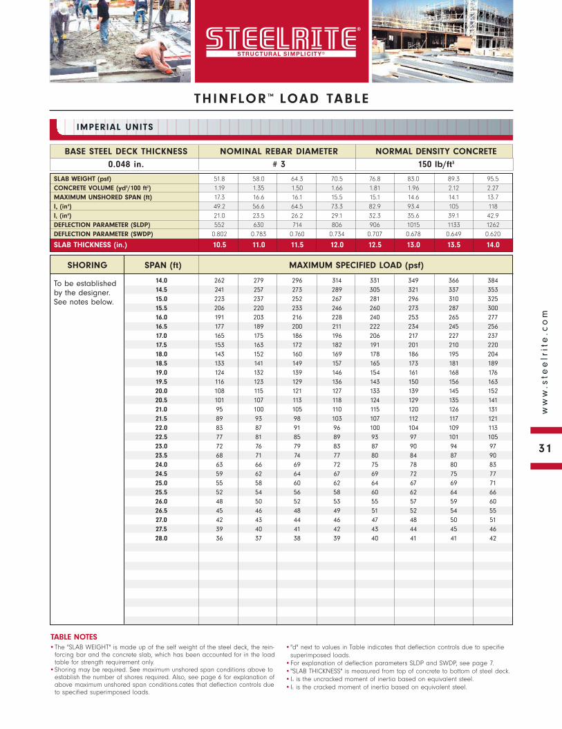
To be established by the designer. See notes below.
NORMAL DENSITY CONCRETE
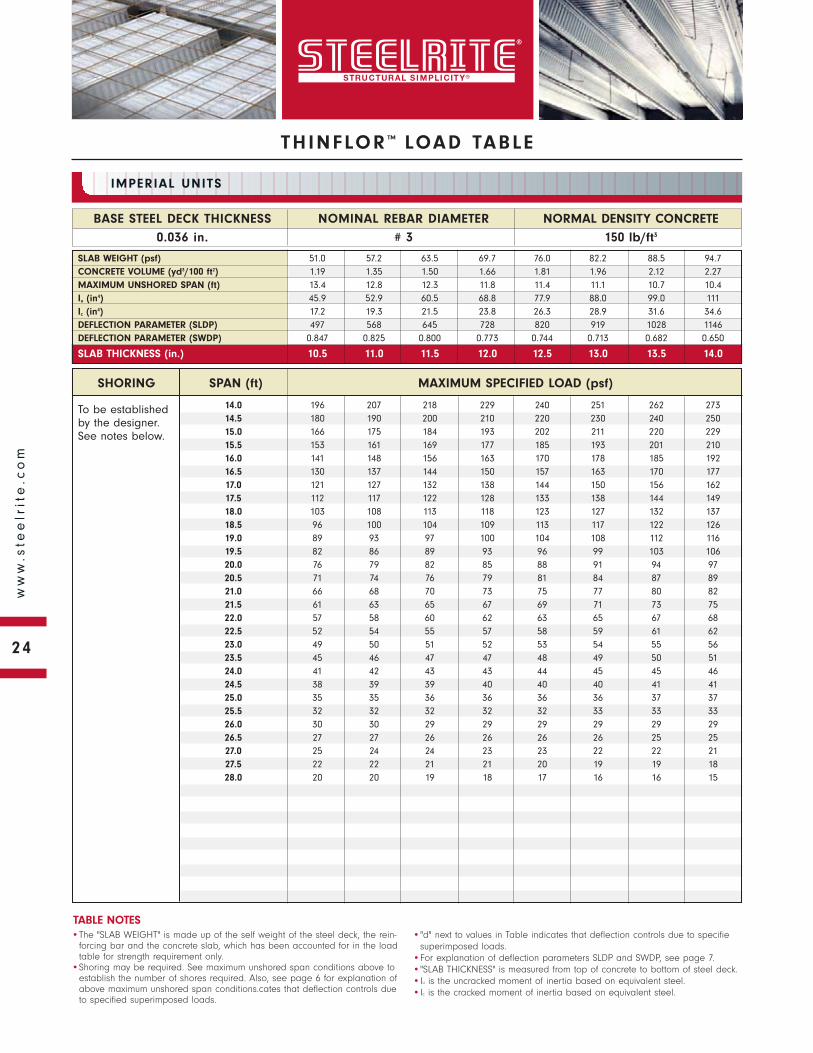
150 lb/ft3
BASE STEEL DECK THICKNESS
0.036 in.
NOMINAL REBAR DIAMETER
# 3
IMPERIAL UNITS
•The "SLAB WEIGHT" is made up of the self weight of the steel deck, the rein-forcing bar and the concrete slab, which has been accounted for in the load table for strength requirement only.
•Shoring may be required. See maximum unshored span conditions above to establish the number of shores required. Also, see page 6 for explanation of above maximum unshored span conditions.cates that deflection controls due to specified superimposed loads.
•"d" next to values in Table indicates that deflection controls due to specifiesuperimposed loads.
•For explanation of deflection parameters SLDP and SWDP, see page 7.•"SLAB THICKNESS" is measured from top of concrete to bottom of steel deck.•Iu is the uncracked moment of inertia based on equivalent steel.•Ic is the cracked moment of inertia based on equivalent steel.
TABLE NOTES
SLAB WEIGHT (psf) 51.0 57.2 63.5 69.7 76.0 82.2 88.5 94.7CONCRETE VOLUME (yd3/100 ft2) 1.19 1.35 1.50 1.66 1.81 1.96 2.12 2.27MAXIMUM UNSHORED SPAN (ft) 13.4 12.8 12.3 11.8 11.4 11.1 10.7 10.4Iu (in4) 45.9 52.9 60.5 68.8 77.9 88.0 99.0 111Ic (in4) 17.2 19.3 21.5 23.8 26.3 28.9 31.6 34.6DEFLECTION PARAMETER (SLDP) 497 568 645 728 820 919 1028 1146DEFLECTION PARAMETER (SWDP) 0.847 0.825 0.800 0.773 0.744 0.713 0.682 0.650
SLAB THICKNESS (in.) 10.5 11.0 11.5 12.0 12.5 13.0 13.5 14.0
14.0 196 207 218 229 240 251 262 27314.5 180 190 200 210 220 230 240 25015.0 166 175 184 193 202 211 220 22915.5 153 161 169 177 185 193 201 21016.0 141 148 156 163 170 178 185 19216.5 130 137 144 150 157 163 170 17717.0 121 127 132 138 144 150 156 16217.5 112 117 122 128 133 138 144 14918.0 103 108 113 118 123 127 132 13718.5 96 100 104 109 113 117 122 12619.0 89 93 97 100 104 108 112 11619.5 82 86 89 93 96 99 103 10620.0 76 79 82 85 88 91 94 9720.5 71 74 76 79 81 84 87 8921.0 66 68 70 73 75 77 80 8221.5 61 63 65 67 69 71 73 7522.0 57 58 60 62 63 65 67 6822.5 52 54 55 57 58 59 61 6223.0 49 50 51 52 53 54 55 5623.5 45 46 47 47 48 49 50 5124.0 41 42 43 43 44 45 45 4624.5 38 39 39 40 40 40 41 4125.0 35 35 36 36 36 36 37 3725.5 32 32 32 32 32 33 33 3326.0 30 30 29 29 29 29 29 2926.5 27 27 26 26 26 26 25 2527.0 25 24 24 23 23 22 22 2127.5 22 22 21 21 20 19 19 1828.0 20 20 19 18 17 16 16 15
THINFLOR ™ LOAD TABLE
SHORING SPAN (ft) MAXIMUM SPECIFIED LOAD (psf)
24
ww
w.s
tee
lrit
e.c
om
THINFLOR ™ LOAD TABLE
To be established by the designer. See notes below.
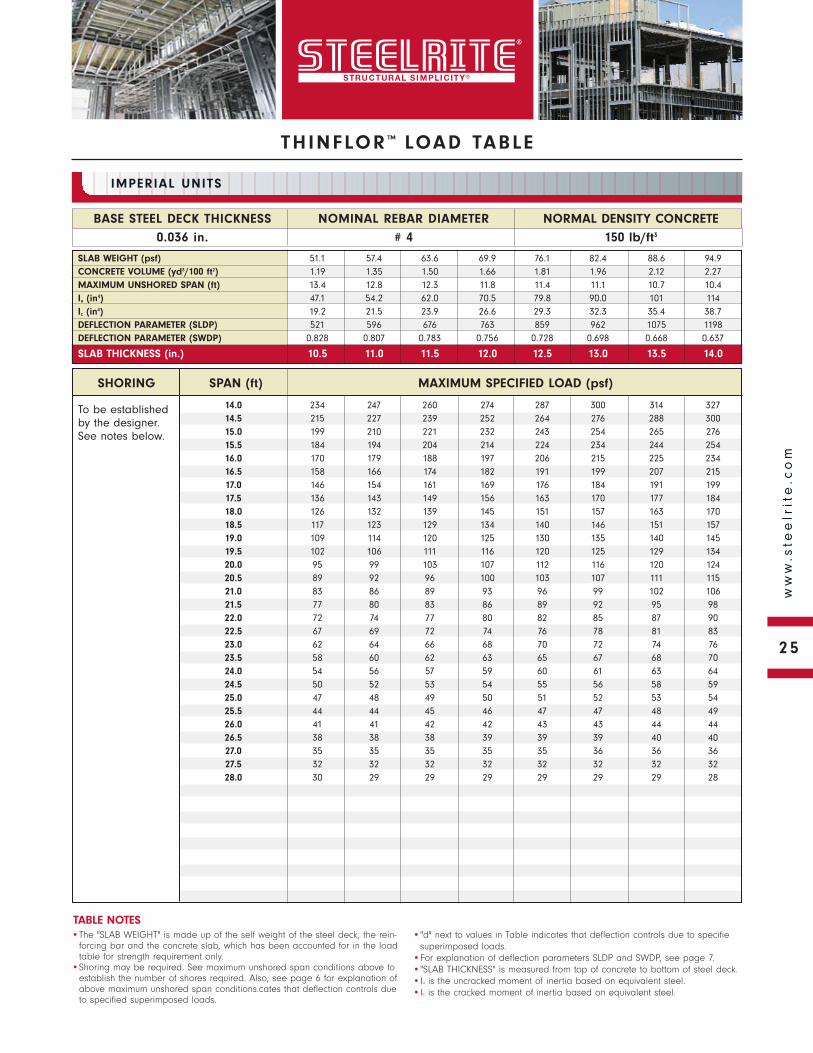
NORMAL DENSITY CONCRETE
150 lb/ft3
BASE STEEL DECK THICKNESS
0.036 in.
NOMINAL REBAR DIAMETER
# 4
IMPERIAL UNITS
•The "SLAB WEIGHT" is made up of the self weight of the steel deck, the rein-forcing bar and the concrete slab, which has been accounted for in the load table for strength requirement only.
•Shoring may be required. See maximum unshored span conditions above to establish the number of shores required. Also, see page 6 for explanation of above maximum unshored span conditions.cates that deflection controls due to specified superimposed loads.
•"d" next to values in Table indicates that deflection controls due to specifiesuperimposed loads.
•For explanation of deflection parameters SLDP and SWDP, see page 7.•"SLAB THICKNESS" is measured from top of concrete to bottom of steel deck.•Iu is the uncracked moment of inertia based on equivalent steel.•Ic is the cracked moment of inertia based on equivalent steel.
TABLE NOTES
SLAB WEIGHT (psf) 51.1 57.4 63.6 69.9 76.1 82.4 88.6 94.9CONCRETE VOLUME (yd3/100 ft2) 1.19 1.35 1.50 1.66 1.81 1.96 2.12 2.27MAXIMUM UNSHORED SPAN (ft) 13.4 12.8 12.3 11.8 11.4 11.1 10.7 10.4Iu (in4) 47.1 54.2 62.0 70.5 79.8 90.0 101 114Ic (in4) 19.2 21.5 23.9 26.6 29.3 32.3 35.4 38.7DEFLECTION PARAMETER (SLDP) 521 596 676 763 859 962 1075 1198DEFLECTION PARAMETER (SWDP) 0.828 0.807 0.783 0.756 0.728 0.698 0.668 0.637
SLAB THICKNESS (in.) 10.5 11.0 11.5 12.0 12.5 13.0 13.5 14.0
SHORING SPAN (ft) MAXIMUM SPECIFIED LOAD (psf)
14.0 234 247 260 274 287 300 314 32714.5 215 227 239 252 264 276 288 30015.0 199 210 221 232 243 254 265 27615.5 184 194 204 214 224 234 244 25416.0 170 179 188 197 206 215 225 23416.5 158 166 174 182 191 199 207 21517.0 146 154 161 169 176 184 191 19917.5 136 143 149 156 163 170 177 18418.0 126 132 139 145 151 157 163 17018.5 117 123 129 134 140 146 151 15719.0 109 114 120 125 130 135 140 14519.5 102 106 111 116 120 125 129 13420.0 95 99 103 107 112 116 120 12420.5 89 92 96 100 103 107 111 11521.0 83 86 89 93 96 99 102 10621.5 77 80 83 86 89 92 95 9822.0 72 74 77 80 82 85 87 9022.5 67 69 72 74 76 78 81 8323.0 62 64 66 68 70 72 74 7623.5 58 60 62 63 65 67 68 7024.0 54 56 57 59 60 61 63 6424.5 50 52 53 54 55 56 58 5925.0 47 48 49 50 51 52 53 5425.5 44 44 45 46 47 47 48 4926.0 41 41 42 42 43 43 44 4426.5 38 38 38 39 39 39 40 4027.0 35 35 35 35 35 36 36 3627.5 32 32 32 32 32 32 32 3228.0 30 29 29 29 29 29 29 28
25
ww
w.s
tee
lrit
e.c
om

To be established by the designer. See notes below.
SHORING SPAN (ft) MAXIMUM SPECIFIED LOAD (psf)
NORMAL DENSITY CONCRETE
150 lb/ft3
BASE STEEL DECK THICKNESS
0.036 in.
NOMINAL REBAR DIAMETER
# 5
IMPERIAL UNITS
•The "SLAB WEIGHT" is made up of the self weight of the steel deck, the rein-forcing bar and the concrete slab, which has been accounted for in the load table for strength requirement only.
•Shoring may be required. See maximum unshored span conditions above to establish the number of shores required. Also, see page 6 for explanation of above maximum unshored span conditions.cates that deflection controls due to specified superimposed loads.
•"d" next to values in Table indicates that deflection controls due to specifiesuperimposed loads.
•For explanation of deflection parameters SLDP and SWDP, see page 7.•"SLAB THICKNESS" is measured from top of concrete to bottom of steel deck.•Iu is the uncracked moment of inertia based on equivalent steel.•Ic is the cracked moment of inertia based on equivalent steel.
TABLE NOTES
SLAB WEIGHT (psf) 51.3 57.6 63.8 70.1 76.3 82.6 88.8 95.1CONCRETE VOLUME (yd3/100 ft2) 1.19 1.35 1.50 1.66 1.81 1.96 2.12 2.27MAXIMUM UNSHORED SPAN (ft) 13.4 12.8 12.3 11.8 11.4 11.1 10.7 10.4Iu (in4) 48.5 55.9 63.9 72.6 82.1 92.5 104 117Ic (in4) 21.5 24.1 26.9 29.9 33.1 36.4 40.0 43.7DEFLECTION PARAMETER (SLDP) 551 629 714 806 906 1015 1133 1261DEFLECTION PARAMETER (SWDP) 0.807 0.786 0.762 0.736 0.709 0.680 0.651 0.622
SLAB THICKNESS (in.) 10.5 11.0 11.5 12.0 12.5 13.0 13.5 14.0
14.0 281 298 314 330 347 363 379 39614.5 260 275 289 304 319 334 349 36415.0 240 254 267 281 295 308 322 33515.5 222 235 247 260 272 285 297 31016.0 206 218 229 241 252 263 275 28616.5 192 202 213 223 233 244 254 26517.0 178 188 197 207 217 226 236 24517.5 166 175 184 192 201 210 219 22718.0 155 163 171 179 187 195 203 21118.5 145 152 159 167 174 181 189 19619.0 135 142 149 155 162 169 175 18219.5 126 132 139 145 151 157 163 16920.0 118 124 129 135 141 146 152 15720.5 111 116 121 126 131 136 141 14621.0 104 108 113 118 122 127 132 13621.5 97 101 106 110 114 118 122 12722.0 91 95 99 102 106 110 114 11822.5 85 89 92 96 99 103 106 10923.0 80 83 86 89 92 95 99 10223.5 75 78 81 83 86 89 92 9424.0 70 73 75 78 80 83 85 8824.5 66 68 70 72 75 77 79 8125.0 62 64 66 67 69 71 73 7525.5 58 60 61 63 64 66 68 6926.0 54 56 57 58 60 61 63 6426.5 51 52 53 54 55 57 58 5927.0 47 48 49 50 51 52 53 5427.5 44 45 46 47 47 48 49 5028.0 41 42 43 43 44 44 45 4528.5 39 39 39 40 40 41 41 4129.0 36 36 36 37 37 37 37 3729.5 34 34 34 34 34 34 34 3430.0 31 31 31 31 31 31 30 30
THINFLOR ™ LOAD TABLE
26
ww
w.s
tee
lrit
e.c
om
THINFLOR ™ LOAD TABLE
To be established by the designer. See notes below.
NORMAL DENSITY CONCRETE
150 lb/ft3
BASE STEEL DECK THICKNESS
0.036 in.
NOMINAL REBAR DIAMETER
# 6
IMPERIAL UNITS
•The "SLAB WEIGHT" is made up of the self weight of the steel deck, the rein-forcing bar and the concrete slab, which has been accounted for in the load table for strength requirement only.
•Shoring may be required. See maximum unshored span conditions above to establish the number of shores required. Also, see page 6 for explanation of above maximum unshored span conditions.cates that deflection controls due to specified superimposed loads.
•"d" next to values in Table indicates that deflection controls due to specifiesuperimposed loads.
•For explanation of deflection parameters SLDP and SWDP, see page 7.•"SLAB THICKNESS" is measured from top of concrete to bottom of steel deck.•Iu is the uncracked moment of inertia based on equivalent steel.•Ic is the cracked moment of inertia based on equivalent steel.
TABLE NOTES
SLAB WEIGHT (psf) 51.6 57.8 64.1 70.3 76.6 82.8 89.1 95.3CONCRETE VOLUME (yd3/100 ft2) 1.19 1.35 1.50 1.66 1.81 1.96 2.12 2.27MAXIMUM UNSHORED SPAN (ft) 13.3 12.8 12.3 11.8 11.4 11.0 10.7 10.4Iu (in4) 50.2 57.8 66.0 75.0 84.8 95.5 107 120Ic (in4) 24.2 27.2 30.4 33.8 37.4 41.2 45.3 49.6DEFLECTION PARAMETER (SLDP) 585 668 758 856 961 1076 1200 1334DEFLECTION PARAMETER (SWDP) 0.784 0.763 0.740 0.715 0.689 0.661 0.633 0.606
SLAB THICKNESS (in.) 10.5 11.0 11.5 12.0 12.5 13.0 13.5 14.0
SHORING SPAN (ft) MAXIMUM SPECIFIED LOAD (psf)
14.0 338 358 378 398 418 438 458 47814.5 313 331 349 367 386 404 422 44115.0 290 306 323 340 357 374 390 40715.5 269 284 300 315 330 346 361 37716.0 250 264 278 292 307 321 335 34916.5 233 246 259 272 285 298 311 32417.0 217 229 241 253 265 277 289 30117.5 202 214 225 236 247 258 269 28018.0 189 199 210 220 230 240 251 26118.5 177 187 196 205 215 224 234 24319.0 166 175 183 192 201 209 218 22719.5 156 164 172 180 188 196 204 21220.0 146 153 161 168 176 183 190 19820.5 137 144 151 158 164 171 178 18521.0 129 135 141 148 154 160 166 17321.5 121 127 133 138 144 150 156 16122.0 114 119 125 130 135 140 146 15122.5 107 112 117 122 127 132 136 14123.0 101 105 110 114 119 123 128 13223.5 95 99 103 107 111 115 119 12424.0 90 93 97 101 104 108 112 11524.5 84 88 91 94 98 101 105 10825.0 79 83 86 89 92 95 98 10125.5 75 78 80 83 86 89 91 9426.0 71 73 76 78 80 83 85 8826.5 66 69 71 73 75 77 80 8227.0 63 65 67 68 70 72 74 7627.5 59 61 62 64 66 68 69 7128.0 56 57 58 60 61 63 64 6628.5 52 54 55 56 57 59 60 6129.0 49 50 51 52 53 54 56 5729.5 46 47 48 49 50 51 51 5230.0 43 44 45 45 46 47 47 48
27
ww
w.s
tee
lrit
e.c
om
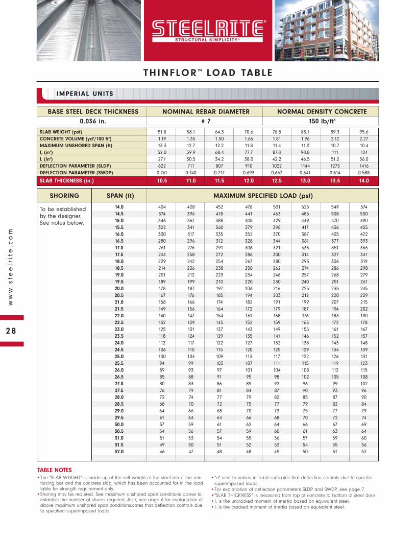
To be established by the designer. See notes below.
SHORING SPAN (ft) MAXIMUM SPECIFIED LOAD (psf)
NORMAL DENSITY CONCRETE
150 lb/ft3
BASE STEEL DECK THICKNESS
0.036 in.
NOMINAL REBAR DIAMETER
# 7
IMPERIAL UNITS
•The "SLAB WEIGHT" is made up of the self weight of the steel deck, the rein-forcing bar and the concrete slab, which has been accounted for in the load table for strength requirement only.
•Shoring may be required. See maximum unshored span conditions above to establish the number of shores required. Also, see page 6 for explanation of above maximum unshored span conditions.cates that deflection controls due to specified superimposed loads.
•"d" next to values in Table indicates that deflection controls due to specifiesuperimposed loads.
•For explanation of deflection parameters SLDP and SWDP, see page 7.•"SLAB THICKNESS" is measured from top of concrete to bottom of steel deck.•Iu is the uncracked moment of inertia based on equivalent steel.•Ic is the cracked moment of inertia based on equivalent steel.
TABLE NOTES
SLAB WEIGHT (psf) 51.8 58.1 64.3 70.6 76.8 83.1 89.3 95.6CONCRETE VOLUME (yd3/100 ft2) 1.19 1.35 1.50 1.66 1.81 1.96 2.12 2.27MAXIMUM UNSHORED SPAN (ft) 13.3 12.7 12.2 11.8 11.4 11.0 10.7 10.4Iu (in4) 52.0 59.9 68.4 77.7 87.8 98.8 111 124Ic (in4) 27.1 30.5 34.2 38.0 42.2 46.5 51.2 56.0DEFLECTION PARAMETER (SLDP) 622 711 807 910 1022 1144 1275 1416DEFLECTION PARAMETER (SWDP) 0.761 0.740 0.717 0.693 0.667 0.641 0.614 0.588
SLAB THICKNESS (in.) 10.5 11.0 11.5 12.0 12.5 13.0 13.5 14.0
14.0 404 428 452 476 501 525 549 57414.5 374 396 418 441 463 485 508 53015.0 346 367 388 408 429 449 470 49015.5 322 341 360 379 398 417 436 45516.0 300 317 335 352 370 387 405 42216.5 280 296 312 328 344 361 377 39317.0 261 276 291 306 321 336 351 36617.5 244 258 272 286 300 314 327 34118.0 229 242 254 267 280 293 306 31918.5 214 226 238 250 262 274 286 29819.0 201 212 223 234 246 257 268 27919.5 189 199 210 220 230 240 251 26120.0 178 187 197 206 216 225 235 24520.5 167 176 185 194 203 212 220 22921.0 158 166 174 182 191 199 207 21521.5 149 156 164 172 179 187 194 20222.0 140 147 154 161 168 176 183 19022.5 132 139 145 152 159 165 172 17823.0 125 131 137 143 149 155 161 16723.5 118 124 129 135 141 146 152 15724.0 112 117 122 127 132 138 143 14824.5 106 110 115 120 125 129 134 13925.0 100 104 109 113 117 122 126 13125.5 94 99 103 107 111 115 119 12326.0 89 93 97 101 104 108 112 11526.5 85 88 91 95 98 102 105 10827.0 80 83 86 89 92 96 99 10227.5 76 79 81 84 87 90 93 9628.0 72 74 77 79 82 85 87 9028.5 68 70 72 75 77 79 82 8429.0 64 66 68 70 73 75 77 7929.5 61 63 64 66 68 70 72 7430.0 57 59 61 62 64 66 67 6930.5 54 56 57 59 60 61 63 6431.0 51 53 54 55 56 57 59 6031.5 49 50 51 52 53 54 55 5632.0 46 47 48 48 49 50 51 52
THINFLOR ™ LOAD TABLE
28
ww
w.s
tee
lrit
e.c
om
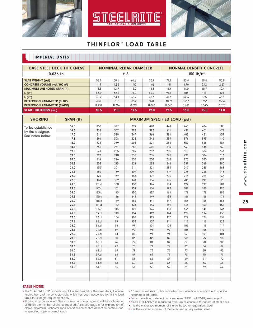
THINFLOR ™ LOAD TABLE
To be established by the designer. See notes below.
NORMAL DENSITY CONCRETE
150 lb/ft3
BASE STEEL DECK THICKNESS
0.036 in.
NOMINAL REBAR DIAMETER
# 8
IMPERIAL UNITS
•The "SLAB WEIGHT" is made up of the self weight of the steel deck, the rein-forcing bar and the concrete slab, which has been accounted for in the load table for strength requirement only.
•Shoring may be required. See maximum unshored span conditions above to establish the number of shores required. Also, see page 6 for explanation of above maximum unshored span conditions.cates that deflection controls due to specified superimposed loads.
•"d" next to values in Table indicates that deflection controls due to specifiesuperimposed loads.
•For explanation of deflection parameters SLDP and SWDP, see page 7.•"SLAB THICKNESS" is measured from top of concrete to bottom of steel deck.•Iu is the uncracked moment of inertia based on equivalent steel.•Ic is the cracked moment of inertia based on equivalent steel.
TABLE NOTES
SLAB WEIGHT (psf) 52.1 58.4 64.6 70.9 77.1 83.4 89.6 95.9CONCRETE VOLUME (yd3/100 ft2) 1.19 1.35 1.50 1.66 1.81 1.96 2.12 2.27MAXIMUM UNSHORED SPAN (ft) 13.3 12.7 12.2 11.8 11.4 11.0 10.7 10.4Iu (in4) 53.9 62.2 71.0 80.7 91.1 103 115 128Ic (in4) 30.2 34.1 38.2 42.6 47.3 52.3 57.5 63.1DEFLECTION PARAMETER (SLDP) 662 757 859 970 1089 1217 1356 1506DEFLECTION PARAMETER (SWDP) 0.737 0.716 0.694 0.670 0.646 0.621 0.595 0.570
SLAB THICKNESS (in.) 10.5 11.0 11.5 12.0 12.5 13.0 13.5 14.0
SHORING SPAN (ft) MAXIMUM SPECIFIED LOAD (psf)
16.0 356 377 399 420 441 463 484 50516.5 332 352 372 392 411 431 451 47117.0 311 329 347 366 384 403 421 43917.5 291 308 325 342 359 376 393 41018.0 273 289 305 321 336 352 368 38418.5 256 271 286 301 315 330 345 36019.0 241 255 269 282 296 310 324 33719.5 227 240 252 265 278 291 304 31720.0 214 226 238 250 262 273 285 29720.5 202 213 224 235 246 257 268 28021.0 190 201 211 221 232 242 253 26321.5 180 189 199 209 219 228 238 24822.0 170 179 188 197 206 215 224 23322.5 161 169 178 186 195 203 211 22023.0 151.d 160 168 176 184 192 199 20723.5 142.d 151 159 166 173 181 188 19624.0 133.d 143 150 157 164 171 178 18524.5 125.d 136 142 149 155 161 168 17425.0 118.d 129 135 141 147 153 158 16425.5 111.d 122 128 133 139 144 150 15526.0 105.d 116 121 126 131 136 141 14726.5 99.d 110 114 119 124 129 134 13827.0 93.d 104 108 113 117 122 126 13127.5 88.d 99 103 107 111 115 119 12328.0 84.d 94 97 101 105 109 113 11728.5 79.d 89 92 96 99 103 106 11029.0 75.d 84 88 91 94 97 101 10429.5 72.d 80 83 86 89 92 95 9830.0 68.d 76 79 81 84 87 90 9230.5 65.d 72 75 77 79 82 84 8731.0 62.d 68 71 73 75 77 80 8231.5 59.d 65 67 69 71 73 75 7732.0 56.d 61 63 65 67 69 71 7232.5 54.d 58 60 61 63 65 66 6833.0 51.d 55 57 58 59 61 62 64
29
ww
w.s
tee
lrit
e.c
om
To be established by the designer. See notes below.
SHORING SPAN (ft) MAXIMUM SPECIFIED LOAD (psf)
NORMAL DENSITY CONCRETE
150 lb/ft3
BASE STEEL DECK THICKNESS
0.036 in.
NOMINAL REBAR DIAMETER
# 9
IMPERIAL UNITS
•The "SLAB WEIGHT" is made up of the self weight of the steel deck, the rein-forcing bar and the concrete slab, which has been accounted for in the load table for strength requirement only.
•Shoring may be required. See maximum unshored span conditions above to establish the number of shores required. Also, see page 6 for explanation of above maximum unshored span conditions.cates that deflection controls due to specified superimposed loads.
•"d" next to values in Table indicates that deflection controls due to specifiesuperimposed loads.
•For explanation of deflection parameters SLDP and SWDP, see page 7.•"SLAB THICKNESS" is measured from top of concrete to bottom of steel deck.•Iu is the uncracked moment of inertia based on equivalent steel.•Ic is the cracked moment of inertia based on equivalent steel.
TABLE NOTES
SLAB WEIGHT (psf) 52.5 58.7 65.0 71.2 77.5 83.7 90.0 96.2CONCRETE VOLUME (yd3/100 ft2) 1.19 1.35 1.50 1.66 1.81 1.96 2.12 2.27MAXIMUM UNSHORED SPAN (ft) 13.3 12.7 12.2 11.7 11.3 11.0 10.7 10.4Iu (in4) 56.0 64.6 73.8 83.8 94.6 106 119 133Ic (in4) 33.4 37.8 42.4 47.4 52.7 58.3 64.2 70.5DEFLECTION PARAMETER (SLDP) 703 805 914 1032 1159 1296 1443 1602DEFLECTION PARAMETER (SWDP) 0.715 0.694 0.671 0.648 0.625 0.600 0.576 0.551
SLAB THICKNESS (in.) 10.5 11.0 11.5 12.0 12.5 13.0 13.5 14.0
18.0 321 341 360 379 399 418 437 45718.5 302 320 338 356 374 392 410 42819.0 284 301 318 335 352 369 385 40219.5 263.d 284 300 315 331 347 363 37820.0 244.d 268 282 297 312 327 341 35620.5 227.d 253 266 280 294 308 322 33521.0 211.d 239 252 265 277 290 303 31621.5 197.d 225.d 238 250 262 274 286 29822.0 183.d 210.d 225 236 248 259 270 28222.5 172.d 196.d 213 224 234 245 256 26623.0 161.d 184.d 202 212 222 232 242 25223.5 151.d 172.d 191 200 210 219 229 23824.0 141.d 162.d 181 190 199 208 216 22524.5 133.d 152.d 172 180 188 197 205 21325.0 125.d 143.d 163.d 171 179 186 194 20225.5 118.d 135.d 153.d 162 169 177 184 19126.0 111.d 127.d 145.d 154 161 168 174 18126.5 105.d 120.d 137.d 146 153 159 165 17227.0 99.d 114.d 129.d 139 145 151 157 16327.5 94.d 108.d 122.d 132 138 143 149 15428.0 89.d 102.d 116.d 125 131 136 141 14628.5 84.d 97.d 110.d 119 124 129 134 13929.0 80.d 92.d 104.d 113 118 122 127 13129.5 76.d 87.d 99.d 108 112 116 120 12530.0 72.d 83.d 94.d 102 106 110 114 11830.5 69.d 79.d 90.d 97 101 105 108 11231.0 66.d 75.d 85.d 92 96 99 103 10631.5 63.d 72.d 81.d 88 91 94 97 10032.0 60.d 68.d 78.d 84 86 89 92 9532.5 57.d 65.d 74.d 79 82 85 87 9033.0 54.d 62.d 71.d 75 78 80 83 8533.5 52.d 59.d 68.d 72 74 76 78 8034.0 50.d 57.d 65.d 68 70 72 74 7634.5 48.d 54.d 62.d 64 66 68 70 7235.0 46.d 52.d 59.d 61 63 64 66 6835.5 44.d 50.d 56 58 59 61 62 6436.0 42.d 48.d 53 55 56 57 59 60
THINFLOR ™ LOAD TABLE
30
ww
w.s
tee
lrit
e.c
om
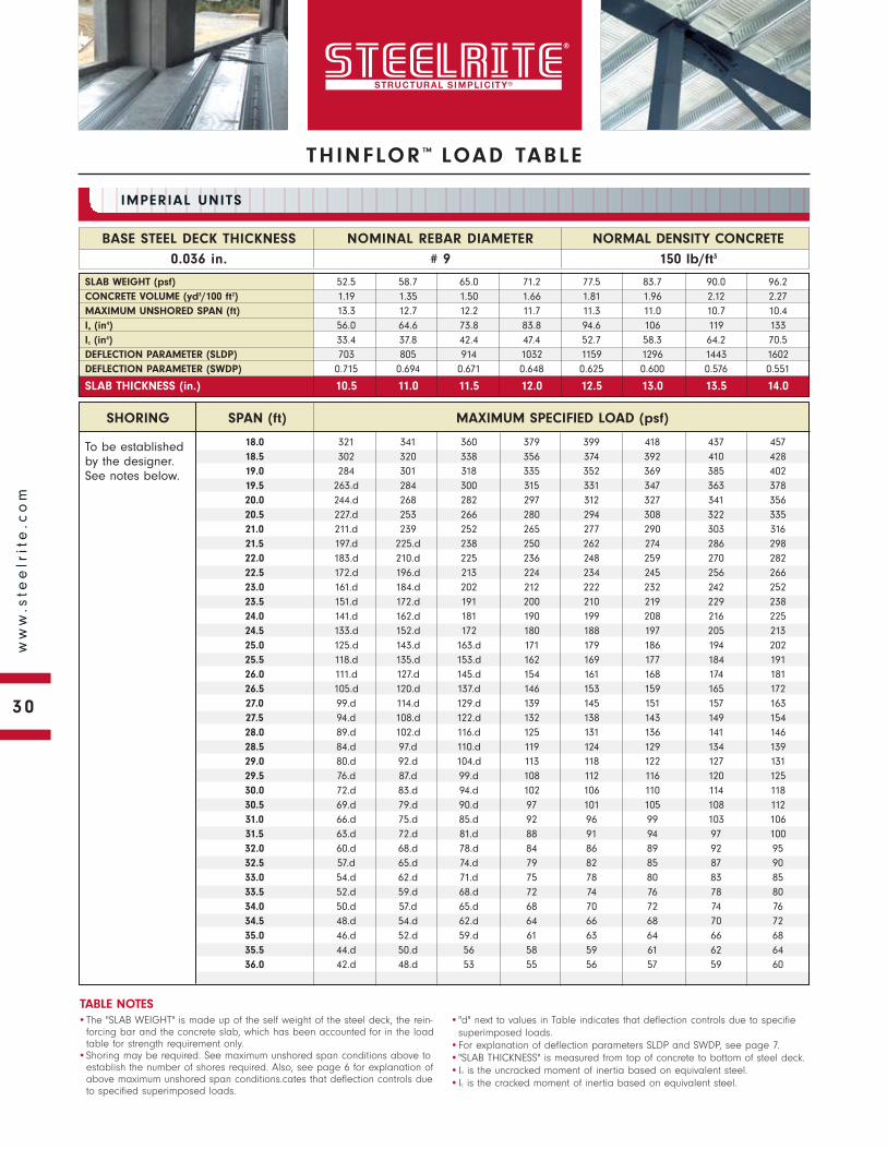
THINFLOR ™ LOAD TABLE
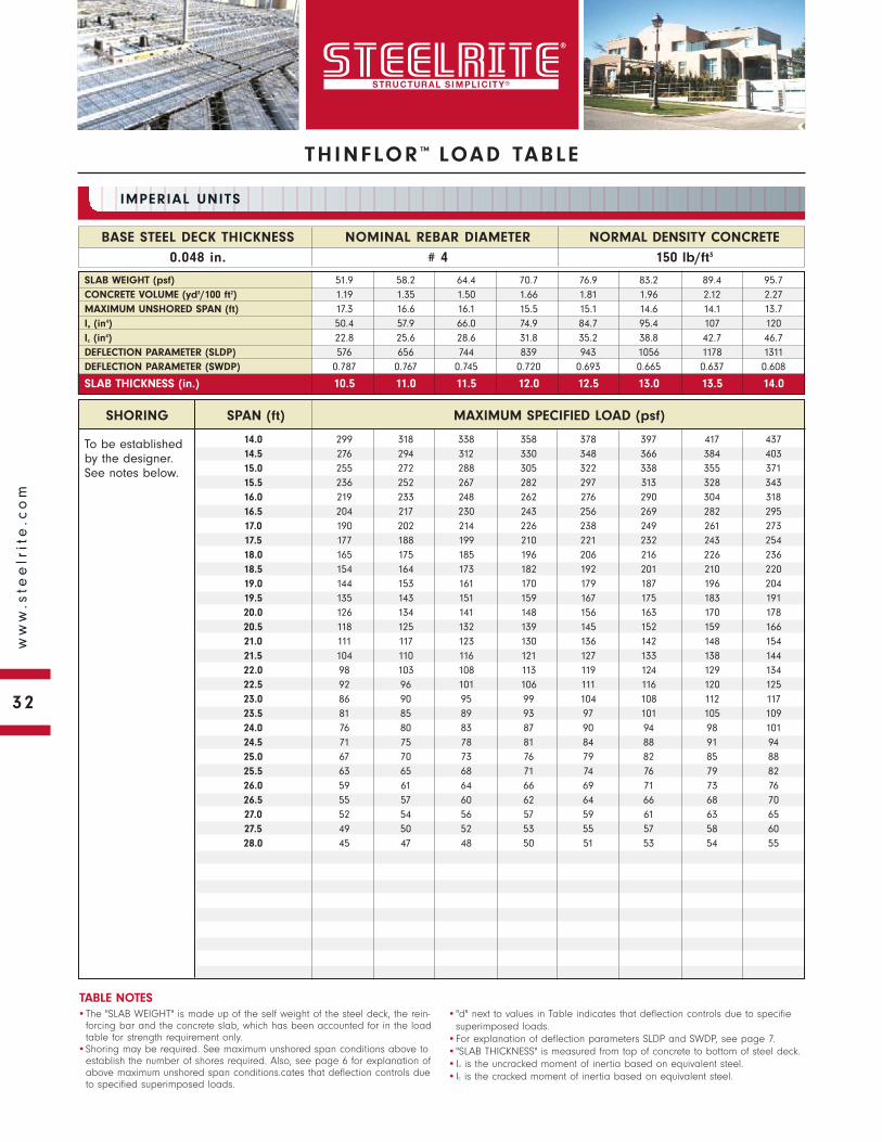
To be established by the designer. See notes below.
NORMAL DENSITY CONCRETE
150 lb/ft3
BASE STEEL DECK THICKNESS
0.048 in.
NOMINAL REBAR DIAMETER
# 3
IMPERIAL UNITS
•The "SLAB WEIGHT" is made up of the self weight of the steel deck, the rein-forcing bar and the concrete slab, which has been accounted for in the load table for strength requirement only.
•Shoring may be required. See maximum unshored span conditions above to establish the number of shores required. Also, see page 6 for explanation of above maximum unshored span conditions.cates that deflection controls due to specified superimposed loads.
•"d" next to values in Table indicates that deflection controls due to specifiesuperimposed loads.
•For explanation of deflection parameters SLDP and SWDP, see page 7.•"SLAB THICKNESS" is measured from top of concrete to bottom of steel deck.•Iu is the uncracked moment of inertia based on equivalent steel.•Ic is the cracked moment of inertia based on equivalent steel.
TABLE NOTES
SLAB WEIGHT (psf) 51.8 58.0 64.3 70.5 76.8 83.0 89.3 95.5CONCRETE VOLUME (yd3/100 ft2) 1.19 1.35 1.50 1.66 1.81 1.96 2.12 2.27MAXIMUM UNSHORED SPAN (ft) 17.3 16.6 16.1 15.5 15.1 14.6 14.1 13.7Iu (in4) 49.2 56.6 64.5 73.3 82.9 93.4 105 118Ic (in4) 21.0 23.5 26.2 29.1 32.3 35.6 39.1 42.9DEFLECTION PARAMETER (SLDP) 552 630 714 806 906 1015 1133 1262DEFLECTION PARAMETER (SWDP) 0.802 0.783 0.760 0.734 0.707 0.678 0.649 0.620
SLAB THICKNESS (in.) 10.5 11.0 11.5 12.0 12.5 13.0 13.5 14.0
SHORING SPAN (ft) MAXIMUM SPECIFIED LOAD (psf)
14.0 262 279 296 314 331 349 366 38414.5 241 257 273 289 305 321 337 35315.0 223 237 252 267 281 296 310 32515.5 206 220 233 246 260 273 287 30016.0 191 203 216 228 240 253 265 27716.5 177 189 200 211 222 234 245 25617.0 165 175 186 196 206 217 227 23717.5 153 163 172 182 191 201 210 22018.0 143 152 160 169 178 186 195 20418.5 133 141 149 157 165 173 181 18919.0 124 132 139 146 154 161 168 17619.5 116 123 129 136 143 150 156 16320.0 108 115 121 127 133 139 145 15220.5 101 107 113 118 124 129 135 14121.0 95 100 105 110 115 120 126 13121.5 89 93 98 103 107 112 117 12122.0 83 87 91 96 100 104 109 11322.5 77 81 85 89 93 97 101 10523.0 72 76 79 83 87 90 94 9723.5 68 71 74 77 80 84 87 9024.0 63 66 69 72 75 78 80 8324.5 59 62 64 67 69 72 75 7725.0 55 58 60 62 64 67 69 7125.5 52 54 56 58 60 62 64 6626.0 48 50 52 53 55 57 59 6026.5 45 46 48 49 51 52 54 5527.0 42 43 44 46 47 48 50 5127.5 39 40 41 42 43 44 45 4628.0 36 37 38 39 40 41 41 42
31
ww
w.s
tee
lrit
e.c
om
To be established by the designer. See notes below.
SHORING SPAN (ft) MAXIMUM SPECIFIED LOAD (psf)
NORMAL DENSITY CONCRETE
150 lb/ft3
BASE STEEL DECK THICKNESS
0.048 in.
NOMINAL REBAR DIAMETER
# 4
IMPERIAL UNITS
•The "SLAB WEIGHT" is made up of the self weight of the steel deck, the rein-forcing bar and the concrete slab, which has been accounted for in the load table for strength requirement only.
•Shoring may be required. See maximum unshored span conditions above to establish the number of shores required. Also, see page 6 for explanation of above maximum unshored span conditions.cates that deflection controls due to specified superimposed loads.
•"d" next to values in Table indicates that deflection controls due to specifiesuperimposed loads.
•For explanation of deflection parameters SLDP and SWDP, see page 7.•"SLAB THICKNESS" is measured from top of concrete to bottom of steel deck.•Iu is the uncracked moment of inertia based on equivalent steel.•Ic is the cracked moment of inertia based on equivalent steel.
TABLE NOTES
SLAB WEIGHT (psf) 51.9 58.2 64.4 70.7 76.9 83.2 89.4 95.7CONCRETE VOLUME (yd3/100 ft2) 1.19 1.35 1.50 1.66 1.81 1.96 2.12 2.27MAXIMUM UNSHORED SPAN (ft) 17.3 16.6 16.1 15.5 15.1 14.6 14.1 13.7Iu (in4) 50.4 57.9 66.0 74.9 84.7 95.4 107 120Ic (in4) 22.8 25.6 28.6 31.8 35.2 38.8 42.7 46.7DEFLECTION PARAMETER (SLDP) 576 656 744 839 943 1056 1178 1311DEFLECTION PARAMETER (SWDP) 0.787 0.767 0.745 0.720 0.693 0.665 0.637 0.608
SLAB THICKNESS (in.) 10.5 11.0 11.5 12.0 12.5 13.0 13.5 14.0
14.0 299 318 338 358 378 397 417 43714.5 276 294 312 330 348 366 384 40315.0 255 272 288 305 322 338 355 37115.5 236 252 267 282 297 313 328 34316.0 219 233 248 262 276 290 304 31816.5 204 217 230 243 256 269 282 29517.0 190 202 214 226 238 249 261 27317.5 177 188 199 210 221 232 243 25418.0 165 175 185 196 206 216 226 23618.5 154 164 173 182 192 201 210 22019.0 144 153 161 170 179 187 196 20419.5 135 143 151 159 167 175 183 19120.0 126 134 141 148 156 163 170 17820.5 118 125 132 139 145 152 159 16621.0 111 117 123 130 136 142 148 15421.5 104 110 116 121 127 133 138 14422.0 98 103 108 113 119 124 129 13422.5 92 96 101 106 111 116 120 12523.0 86 90 95 99 104 108 112 11723.5 81 85 89 93 97 101 105 10924.0 76 80 83 87 90 94 98 10124.5 71 75 78 81 84 88 91 9425.0 67 70 73 76 79 82 85 8825.5 63 65 68 71 74 76 79 8226.0 59 61 64 66 69 71 73 7626.5 55 57 60 62 64 66 68 7027.0 52 54 56 57 59 61 63 6527.5 49 50 52 53 55 57 58 6028.0 45 47 48 50 51 53 54 55
THINFLOR ™ LOAD TABLE
32
ww
w.s
tee
lrit
e.c
om

THINFLOR ™ LOAD TABLE
To be established by the designer. See notes below.
NORMAL DENSITY CONCRETE
150 lb/ft3
BASE STEEL DECK THICKNESS
0.048 in.
NOMINAL REBAR DIAMETER
# 5
IMPERIAL UNITS
•The "SLAB WEIGHT" is made up of the self weight of the steel deck, the rein-forcing bar and the concrete slab, which has been accounted for in the load table for strength requirement only.
•Shoring may be required. See maximum unshored span conditions above to establish the number of shores required. Also, see page 6 for explanation of above maximum unshored span conditions.cates that deflection controls due to specified superimposed loads.
•"d" next to values in Table indicates that deflection controls due to specifiesuperimposed loads.
•For explanation of deflection parameters SLDP and SWDP, see page 7.•"SLAB THICKNESS" is measured from top of concrete to bottom of steel deck.•Iu is the uncracked moment of inertia based on equivalent steel.•Ic is the cracked moment of inertia based on equivalent steel.
TABLE NOTES
SLAB WEIGHT (psf) 52.1 58.4 64.6 70.9 77.1 83.4 89.6 95.9CONCRETE VOLUME (yd3/100 ft2) 1.19 1.35 1.50 1.66 1.81 1.96 2.12 2.27MAXIMUM UNSHORED SPAN (ft) 17.3 16.6 16.0 15.5 15.0 14.5 14.1 13.7Iu (in4) 51.7 59.5 67.8 76.9 86.9 97.8 110 123Ic (in4) 25.0 28.1 31.4 34.9 38.7 42.7 47.0 51.5DEFLECTION PARAMETER (SLDP) 604 689 780 880 988 1106 1233 1372DEFLECTION PARAMETER (SWDP) 0.768 0.749 0.727 0.703 0.677 0.650 0.623 0.595
SLAB THICKNESS (in.) 10.5 11.0 11.5 12.0 12.5 13.0 13.5 14.0
SHORING SPAN (ft) MAXIMUM SPECIFIED LOAD (psf)
14.0 345 368 391 413 436 459 482 50514.5 319 340 361 382 403 424 445 46515.0 296 315 334 353 373 392 411 43015.5 274 292 310 327 345 363 381 39816.0 255 271 288 304 320 337 353 36916.5 237 253 268 283 298 313 328 34317.0 221 235 249 263 277 291 305 31917.5 207 220 233 245 258 271 284 29718.0 193 205 217 229 241 253 265 27718.5 181 192 203 214 225 236 247 25819.0 169 180 190 200 210 221 231 24119.5 159 168 178 187 197 206 216 22520.0 149 158 167 175 184 193 202 21120.5 140 148 156 164 173 181 189 19721.0 132 139 147 154 162 169 177 18421.5 124 131 138 145 152 159 166 17322.0 116 123 129 136 142 149 155 16222.5 110 116 122 127 133 139 145 15123.0 103 109 114 120 125 131 136 14223.5 97 102 107 112 118 123 128 13324.0 92 96 101 106 110 115 120 12424.5 86 91 95 99 103 108 112 11625.0 81 85 89 93 97 101 105 10925.5 77 80 84 87 91 95 98 10226.0 72 76 79 82 85 89 92 9526.5 68 71 74 77 80 83 86 8927.0 64 67 70 72 75 78 80 8327.5 60 63 65 68 70 73 75 7728.0 57 59 61 63 66 68 70 7228.5 54 56 57 59 61 63 65 6729.0 50 52 54 56 57 59 61 6229.5 47 49 50 52 53 55 56 5830.0 45 46 47 48 50 51 52 54
33
ww
w.s
tee
lrit
e.c
om
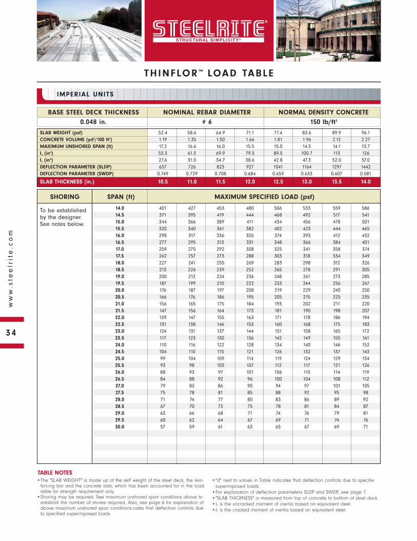
To be established by the designer. See notes below.
SHORING SPAN (ft) MAXIMUM SPECIFIED LOAD (psf)
NORMAL DENSITY CONCRETE
150 lb/ft3
BASE STEEL DECK THICKNESS
0.048 in.
NOMINAL REBAR DIAMETER
# 6
IMPERIAL UNITS
•The "SLAB WEIGHT" is made up of the self weight of the steel deck, the rein-forcing bar and the concrete slab, which has been accounted for in the load table for strength requirement only.
•Shoring may be required. See maximum unshored span conditions above to establish the number of shores required. Also, see page 6 for explanation of above maximum unshored span conditions.cates that deflection controls due to specified superimposed loads.
•"d" next to values in Table indicates that deflection controls due to specifiesuperimposed loads.
•For explanation of deflection parameters SLDP and SWDP, see page 7.•"SLAB THICKNESS" is measured from top of concrete to bottom of steel deck.•Iu is the uncracked moment of inertia based on equivalent steel.•Ic is the cracked moment of inertia based on equivalent steel.
TABLE NOTES
SLAB WEIGHT (psf) 52.4 58.6 64.9 71.1 77.4 83.6 89.9 96.1CONCRETE VOLUME (yd3/100 ft2) 1.19 1.35 1.50 1.66 1.81 1.96 2.12 2.27MAXIMUM UNSHORED SPAN (ft) 17.2 16.6 16.0 15.5 15.0 14.5 14.1 13.7Iu (in4) 53.3 61.3 69.9 79.3 89.5 100.7 113 126Ic (in4) 27.6 31.0 34.7 38.6 42.8 47.3 52.0 57.0DEFLECTION PARAMETER (SLDP) 637 726 823 927 1041 1164 1297 1442DEFLECTION PARAMETER (SWDP) 0.749 0.729 0.708 0.684 0.659 0.633 0.607 0.581
SLAB THICKNESS (in.) 10.5 11.0 11.5 12.0 12.5 13.0 13.5 14.0
14.0 401 427 453 480 506 533 559 58614.5 371 395 419 444 468 492 517 54115.0 344 366 389 411 434 456 478 50115.5 320 340 361 382 402 423 444 46516.0 298 317 336 355 374 393 412 43216.5 277 295 313 331 348 366 384 40117.0 259 275 292 308 325 341 358 37417.5 242 257 273 288 303 318 334 34918.0 227 241 255 269 283 298 312 32618.5 213 226 239 252 265 278 291 30519.0 200 212 224 236 248 261 273 28519.5 187 199 210 222 233 244 256 26720.0 176 187 197 208 219 229 240 25020.5 166 176 186 195 205 215 225 23521.0 156 165 175 184 193 202 211 22021.5 147 156 164 173 181 190 198 20722.0 139 147 155 163 171 178 186 19422.5 131 138 146 153 160 168 175 18323.0 124 131 137 144 151 158 165 17223.5 117 123 130 136 142 149 155 16124.0 110 116 122 128 134 140 146 15224.5 104 110 115 121 126 132 137 14325.0 99 104 109 114 119 124 129 13425.5 93 98 103 107 112 117 121 12626.0 88 93 97 101 106 110 114 11926.5 84 88 92 96 100 104 108 11227.0 79 83 86 90 94 97 101 10527.5 75 78 81 85 88 92 95 9828.0 71 74 77 80 83 86 89 9228.5 67 70 73 75 78 81 84 8729.0 63 66 68 71 74 76 79 8129.5 60 62 64 67 69 71 74 7630.0 57 59 61 63 65 67 69 71
THINFLOR ™ LOAD TABLE
34
ww
w.s
tee
lrit
e.c
om
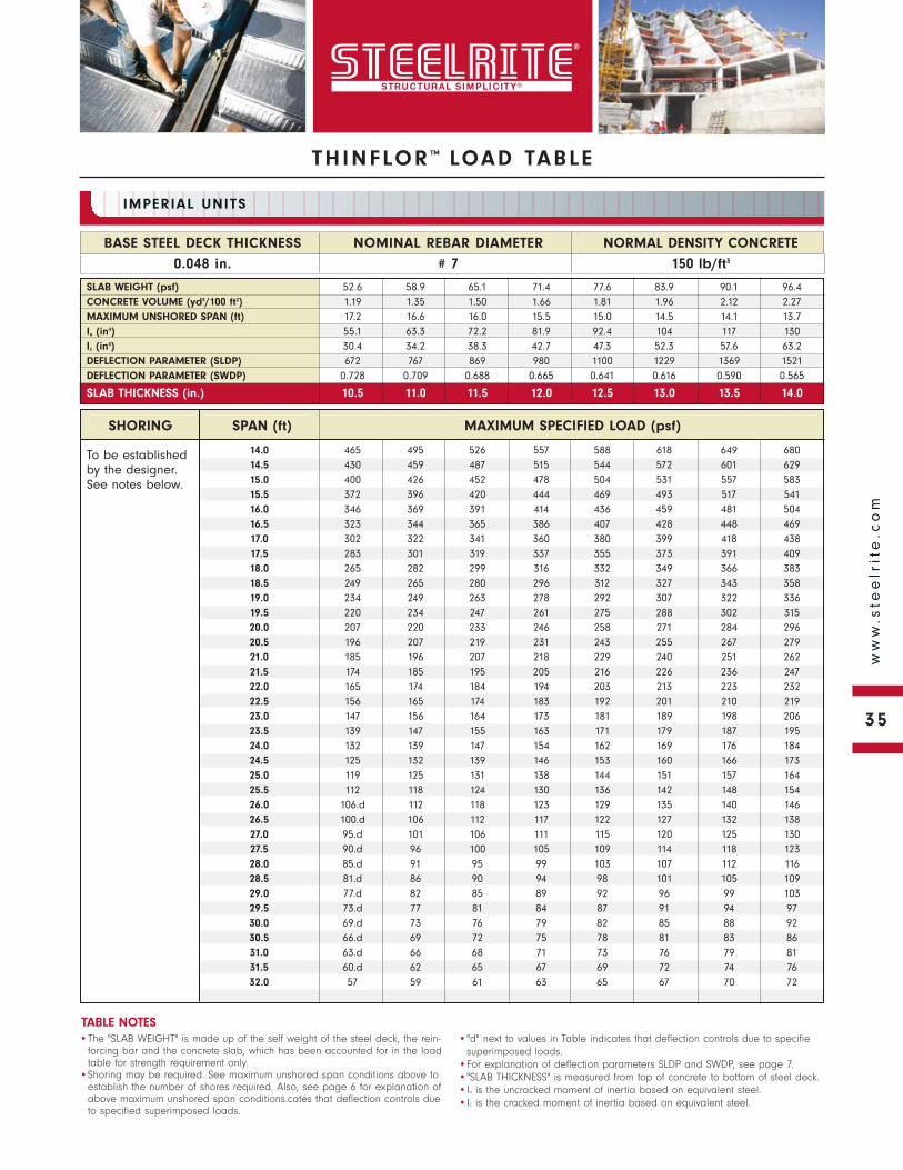
THINFLOR ™ LOAD TABLE
To be established by the designer. See notes below.
NORMAL DENSITY CONCRETE
150 lb/ft3
BASE STEEL DECK THICKNESS
0.048 in.
NOMINAL REBAR DIAMETER
# 7
IMPERIAL UNITS
•The "SLAB WEIGHT" is made up of the self weight of the steel deck, the rein-forcing bar and the concrete slab, which has been accounted for in the load table for strength requirement only.
•Shoring may be required. See maximum unshored span conditions above to establish the number of shores required. Also, see page 6 for explanation of above maximum unshored span conditions.cates that deflection controls due to specified superimposed loads.
•"d" next to values in Table indicates that deflection controls due to specifiesuperimposed loads.
•For explanation of deflection parameters SLDP and SWDP, see page 7.•"SLAB THICKNESS" is measured from top of concrete to bottom of steel deck.•Iu is the uncracked moment of inertia based on equivalent steel.•Ic is the cracked moment of inertia based on equivalent steel.
TABLE NOTES
SLAB WEIGHT (psf) 52.6 58.9 65.1 71.4 77.6 83.9 90.1 96.4CONCRETE VOLUME (yd3/100 ft2) 1.19 1.35 1.50 1.66 1.81 1.96 2.12 2.27MAXIMUM UNSHORED SPAN (ft) 17.2 16.6 16.0 15.5 15.0 14.5 14.1 13.7Iu (in4) 55.1 63.3 72.2 81.9 92.4 104 117 130Ic (in4) 30.4 34.2 38.3 42.7 47.3 52.3 57.6 63.2DEFLECTION PARAMETER (SLDP) 672 767 869 980 1100 1229 1369 1521DEFLECTION PARAMETER (SWDP) 0.728 0.709 0.688 0.665 0.641 0.616 0.590 0.565
SLAB THICKNESS (in.) 10.5 11.0 11.5 12.0 12.5 13.0 13.5 14.0
SHORING SPAN (ft) MAXIMUM SPECIFIED LOAD (psf)
14.0 465 495 526 557 588 618 649 68014.5 430 459 487 515 544 572 601 62915.0 400 426 452 478 504 531 557 58315.5 372 396 420 444 469 493 517 54116.0 346 369 391 414 436 459 481 50416.5 323 344 365 386 407 428 448 46917.0 302 322 341 360 380 399 418 43817.5 283 301 319 337 355 373 391 40918.0 265 282 299 316 332 349 366 38318.5 249 265 280 296 312 327 343 35819.0 234 249 263 278 292 307 322 33619.5 220 234 247 261 275 288 302 31520.0 207 220 233 246 258 271 284 29620.5 196 207 219 231 243 255 267 27921.0 185 196 207 218 229 240 251 26221.5 174 185 195 205 216 226 236 24722.0 165 174 184 194 203 213 223 23222.5 156 165 174 183 192 201 210 21923.0 147 156 164 173 181 189 198 20623.5 139 147 155 163 171 179 187 19524.0 132 139 147 154 162 169 176 18424.5 125 132 139 146 153 160 166 17325.0 119 125 131 138 144 151 157 16425.5 112 118 124 130 136 142 148 15426.0 106.d 112 118 123 129 135 140 14626.5 100.d 106 112 117 122 127 132 13827.0 95.d 101 106 111 115 120 125 13027.5 90.d 96 100 105 109 114 118 12328.0 85.d 91 95 99 103 107 112 11628.5 81.d 86 90 94 98 101 105 10929.0 77.d 82 85 89 92 96 99 10329.5 73.d 77 81 84 87 91 94 9730.0 69.d 73 76 79 82 85 88 9230.5 66.d 69 72 75 78 81 83 8631.0 63.d 66 68 71 73 76 79 8131.5 60.d 62 65 67 69 72 74 7632.0 57 59 61 63 65 67 70 72
35
ww
w.s
tee
lrit
e.c
om
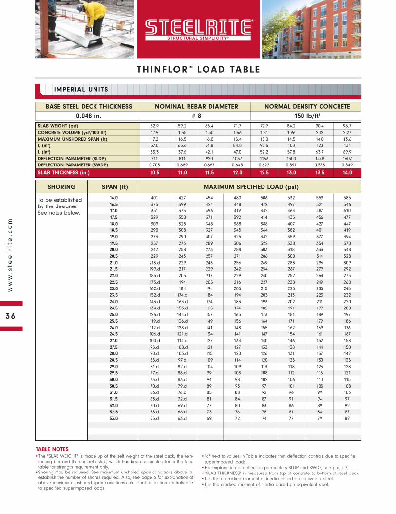
To be established by the designer. See notes below.
SHORING SPAN (ft) MAXIMUM SPECIFIED LOAD (psf)
NORMAL DENSITY CONCRETE
150 lb/ft3
BASE STEEL DECK THICKNESS
0.048 in.
NOMINAL REBAR DIAMETER
# 8
IMPERIAL UNITS
•The "SLAB WEIGHT" is made up of the self weight of the steel deck, the rein-forcing bar and the concrete slab, which has been accounted for in the load table for strength requirement only.
•Shoring may be required. See maximum unshored span conditions above to establish the number of shores required. Also, see page 6 for explanation of above maximum unshored span conditions.cates that deflection controls due to specified superimposed loads.
•"d" next to values in Table indicates that deflection controls due to specifiesuperimposed loads.
•For explanation of deflection parameters SLDP and SWDP, see page 7.•"SLAB THICKNESS" is measured from top of concrete to bottom of steel deck.•Iu is the uncracked moment of inertia based on equivalent steel.•Ic is the cracked moment of inertia based on equivalent steel.
TABLE NOTES
SLAB WEIGHT (psf) 52.9 59.2 65.4 71.7 77.9 84.2 90.4 96.7CONCRETE VOLUME (yd3/100 ft2) 1.19 1.35 1.50 1.66 1.81 1.96 2.12 2.27MAXIMUM UNSHORED SPAN (ft) 17.2 16.5 16.0 15.4 15.0 14.5 14.0 13.6Iu (in4) 57.0 65.6 74.8 84.8 95.6 108 120 134Ic (in4) 33.3 37.6 42.1 47.0 52.2 57.8 63.7 69.9DEFLECTION PARAMETER (SLDP) 711 811 920 1037 1163 1300 1448 1607DEFLECTION PARAMETER (SWDP) 0.708 0.689 0.667 0.645 0.622 0.597 0.573 0.549
SLAB THICKNESS (in.) 10.5 11.0 11.5 12.0 12.5 13.0 13.5 14.0
16.0 401 427 454 480 506 532 559 58516.5 375 399 424 448 472 497 521 54617.0 351 373 396 419 442 464 487 51017.5 329 350 371 392 414 435 456 47718.0 309 328 348 368 388 407 427 44718.5 290 308 327 345 364 382 401 41919.0 273 290 307 325 342 359 377 39419.5 257 273 289 306 322 338 354 37020.0 242 258 273 288 303 318 333 34820.5 229 243 257 271 286 300 314 32821.0 213.d 229 243 256 269 283 296 30921.5 199.d 217 229 242 254 267 279 29222.0 185.d 205 217 229 240 252 264 27522.5 173.d 194 205 216 227 238 249 26023.0 162.d 184 194 205 215 225 235 24623.5 152.d 174.d 184 194 203 213 223 23224.0 143.d 163.d 174 183 193 202 211 22024.5 134.d 153.d 165 174 182 191 199 20825.0 126.d 144.d 157 165 173 181 189 19725.5 119.d 136.d 149 156 164 171 179 18626.0 112.d 128.d 141 148 155 162 169 17626.5 106.d 121.d 134 141 147 154 161 16727.0 100.d 114.d 127 134 140 146 152 15827.5 95.d 108.d 121 127 133 138 144 15028.0 90.d 103.d 115 120 126 131 137 14228.5 85.d 97.d 109 114 120 125 130 13529.0 81.d 92.d 104 109 113 118 123 12829.5 77.d 88.d 99 103 108 112 116 12130.0 73.d 83.d 94 98 102 106 110 11530.5 70.d 79.d 89 93 97 101 105 10831.0 66.d 76.d 85 88 92 96 99 10331.5 63.d 72.d 81 84 87 91 94 9732.0 60.d 69.d 77 80 83 86 89 9232.5 58.d 66.d 73 76 78 81 84 8733.0 55.d 63.d 69 72 74 77 79 82
THINFLOR ™ LOAD TABLE
36
ww
w.s
tee
lrit
e.c
om

THINFLOR ™ LOAD TABLE
To be established by the designer. See notes below.
NORMAL DENSITY CONCRETE
150 lb/ft3
BASE STEEL DECK THICKNESS
0.048 in.
NOMINAL REBAR DIAMETER
# 9
IMPERIAL UNITS
•The "SLAB WEIGHT" is made up of the self weight of the steel deck, the rein-forcing bar and the concrete slab, which has been accounted for in the load table for strength requirement only.
•Shoring may be required. See maximum unshored span conditions above to establish the number of shores required. Also, see page 6 for explanation of above maximum unshored span conditions.cates that deflection controls due to specified superimposed loads.
•"d" next to values in Table indicates that deflection controls due to specifiesuperimposed loads.
•For explanation of deflection parameters SLDP and SWDP, see page 7.•"SLAB THICKNESS" is measured from top of concrete to bottom of steel deck.•Iu is the uncracked moment of inertia based on equivalent steel.•Ic is the cracked moment of inertia based on equivalent steel.
TABLE NOTES
SLAB WEIGHT (psf) 53.3 59.5 65.8 72.0 78.3 84.5 90.8 97.0CONCRETE VOLUME (yd3/100 ft2) 1.19 1.35 1.50 1.66 1.81 1.96 2.12 2.27MAXIMUM UNSHORED SPAN (ft) 17.1 16.5 15.9 15.4 14.9 14.5 14.0 13.6Iu (in4) 59.0 67.9 77.5 87.8 99.1 111 125 139Ic (in4) 36.4 41.1 46.2 51.6 57.4 63.6 70.1 77.0DEFLECTION PARAMETER (SLDP) 751 858 973 1097 1231 1376 1532 1700DEFLECTION PARAMETER (SWDP) 0.689 0.669 0.648 0.626 0.603 0.579 0.556 0.532
SLAB THICKNESS (in.) 10.5 11.0 11.5 12.0 12.5 13.0 13.5 14.0
SHORING SPAN (ft) MAXIMUM SPECIFIED LOAD (psf)
18.0 356 379 402 425 449 472 495 51818.5 329.d 356 378 400 422 443 465 48719.0 304.d 336 356 376 397 417 437 45819.5 281.d 316 335 355 374 393 412 43120.0 261.d 298.d 316 334 352 370 388 40620.5 242.d 277.d 299 316 332 349 366 38321.0 225.d 257.d 282 298 314 330 346 36121.5 210.d 240.d 267 282 297 312 327 34122.0 196.d 224.d 253 267 281 295 309 32322.5 183.d 209.d 237.d 253 266 279 292 30523.0 171.d 196.d 222.d 240 252 264 277 28923.5 161.d 184.d 208.d 227 239 251 262 27424.0 151.d 172.d 195.d 216 227 238 249 26024.5 142.d 162.d 184.d 205 215 226 236 24625.0 133.d 152.d 173.d 195 204 214 224 23425.5 126.d 144.d 163.d 184.d 194 203 213 22226.0 119.d 136.d 154.d 173.d 184 193 202 21126.5 112.d 128.d 145.d 164.d 175 184 192 20027.0 106.d 121.d 137.d 155.d 167 174 182 19027.5 100.d 115.d 130.d 147.d 159 166 173 18028.0 95.d 109.d 123.d 139.d 151 158 165 17128.5 90.d 103.d 117.d 132.d 144 150 157 16329.0 86.d 98.d 111.d 125.d 137 143 149 15529.5 81.d 93.d 105.d 119.d 130 136 142 14730.0 77.d 88.d 100.d 113.d 124 129 135 14030.5 73.d 84.d 95.d 107.d 118 123 128 13331.0 70.d 80.d 91.d 102.d 112 117 122 12631.5 67.d 76.d 86.d 97.d 107 111 116 12032.0 64.d 73.d 82.d 93.d 102 106 110 11432.5 61.d 69.d 79.d 89.d 97 101 105 10933.0 58.d 66.d 75.d 85.d 92 96 99 10333.5 55.d 63.d 72.d 81.d 88 91 94 9834.0 53.d 61.d 69.d 78.d 83 87 90 9334.5 51.d 58.d 66.d 74.d 79 82 85 8835.0 49.d 56.d 63.d 71.d 75 78 81 8435.5 47.d 53.d 60.d 68.d 72 74 77 7936.0 45.d 51.d 58.d 65.d 68 70 73 75
37
ww
w.s
tee
lrit
e.c
om
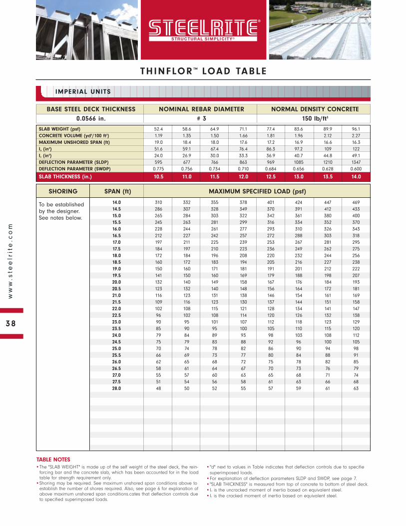
To be established by the designer. See notes below.
SHORING SPAN (ft) MAXIMUM SPECIFIED LOAD (psf)
NORMAL DENSITY CONCRETE
150 lb/ft3
BASE STEEL DECK THICKNESS
0.0566 in.
NOMINAL REBAR DIAMETER
# 3
IMPERIAL UNITS
•The "SLAB WEIGHT" is made up of the self weight of the steel deck, the rein-forcing bar and the concrete slab, which has been accounted for in the load table for strength requirement only.
•Shoring may be required. See maximum unshored span conditions above to establish the number of shores required. Also, see page 6 for explanation of above maximum unshored span conditions.cates that deflection controls due to specified superimposed loads.
•"d" next to values in Table indicates that deflection controls due to specifiesuperimposed loads.
•For explanation of deflection parameters SLDP and SWDP, see page 7.•"SLAB THICKNESS" is measured from top of concrete to bottom of steel deck.•Iu is the uncracked moment of inertia based on equivalent steel.•Ic is the cracked moment of inertia based on equivalent steel.
TABLE NOTES
SLAB WEIGHT (psf) 52.4 58.6 64.9 71.1 77.4 83.6 89.9 96.1CONCRETE VOLUME (yd3/100 ft2) 1.19 1.35 1.50 1.66 1.81 1.96 2.12 2.27MAXIMUM UNSHORED SPAN (ft) 19.0 18.4 18.0 17.6 17.2 16.9 16.6 16.3Iu (in4) 51.6 59.1 67.4 76.4 86.3 97.2 109 122Ic (in4) 24.0 26.9 30.0 33.3 36.9 40.7 44.8 49.1DEFLECTION PARAMETER (SLDP) 595 677 766 863 969 1085 1210 1347DEFLECTION PARAMETER (SWDP) 0.775 0.756 0.734 0.710 0.684 0.656 0.628 0.600
SLAB THICKNESS (in.) 10.5 11.0 11.5 12.0 12.5 13.0 13.5 14.0
14.0 310 332 355 378 401 424 447 46914.5 286 307 328 349 370 391 412 43315.0 265 284 303 322 342 361 380 40015.5 245 263 281 299 316 334 352 37016.0 228 244 261 277 293 310 326 34316.5 212 227 242 257 272 288 303 31817.0 197 211 225 239 253 267 281 29517.5 184 197 210 223 236 249 262 27518.0 172 184 196 208 220 232 244 25618.5 160 172 183 194 205 216 227 23819.0 150 160 171 181 191 201 212 22219.5 141 150 160 169 179 188 198 20720.0 132 140 149 158 167 176 184 19320.5 123 132 140 148 156 164 172 18121.0 116 123 131 138 146 154 161 16921.5 109 116 123 130 137 144 151 15822.0 102 108 115 121 128 134 141 14722.5 96 102 108 114 120 126 132 13823.0 90 95 101 107 112 118 123 12923.5 85 90 95 100 105 110 115 12024.0 79 84 89 93 98 103 108 11224.5 75 79 83 88 92 96 100 10525.0 70 74 78 82 86 90 94 9825.5 66 69 73 77 80 84 88 9126.0 62 65 68 72 75 78 82 8526.5 58 61 64 67 70 73 76 7927.0 55 57 60 63 65 68 71 7427.5 51 54 56 58 61 63 66 6828.0 48 50 52 55 57 59 61 63
THINFLOR ™ LOAD TABLE
38
ww
w.s
tee
lrit
e.c
om
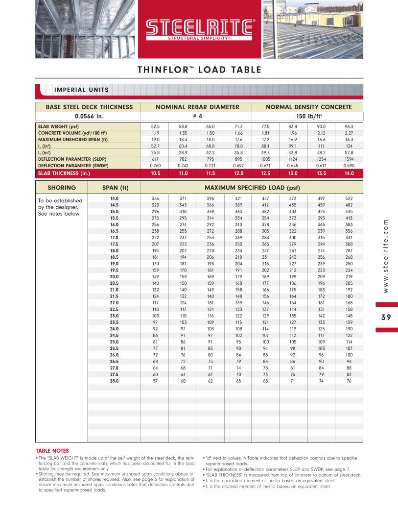
THINFLOR ™ LOAD TABLE
To be established by the designer. See notes below.
NORMAL DENSITY CONCRETE
150 lb/ft3
BASE STEEL DECK THICKNESS
0.0566 in.
NOMINAL REBAR DIAMETER
# 4
IMPERIAL UNITS
•The "SLAB WEIGHT" is made up of the self weight of the steel deck, the rein-forcing bar and the concrete slab, which has been accounted for in the load table for strength requirement only.
•Shoring may be required. See maximum unshored span conditions above to establish the number of shores required. Also, see page 6 for explanation of above maximum unshored span conditions.cates that deflection controls due to specified superimposed loads.
•"d" next to values in Table indicates that deflection controls due to specifiesuperimposed loads.
•For explanation of deflection parameters SLDP and SWDP, see page 7.•"SLAB THICKNESS" is measured from top of concrete to bottom of steel deck.•Iu is the uncracked moment of inertia based on equivalent steel.•Ic is the cracked moment of inertia based on equivalent steel.
TABLE NOTES
SLAB WEIGHT (psf) 52.5 58.8 65.0 71.3 77.5 83.8 90.0 96.3CONCRETE VOLUME (yd3/100 ft2) 1.19 1.35 1.50 1.66 1.81 1.96 2.12 2.27MAXIMUM UNSHORED SPAN (ft) 19.0 18.4 18.0 17.6 17.2 16.9 16.6 16.3Iu (in4) 52.7 60.4 68.8 78.0 88.1 99.1 111 124Ic (in4) 25.8 28.9 32.2 35.8 39.7 43.8 48.2 52.8DEFLECTION PARAMETER (SLDP) 617 702 795 895 1005 1124 1254 1394DEFLECTION PARAMETER (SWDP) 0.760 0.742 0.721 0.697 0.671 0.645 0.617 0.590
SLAB THICKNESS (in.) 10.5 11.0 11.5 12.0 12.5 13.0 13.5 14.0
SHORING SPAN (ft) MAXIMUM SPECIFIED LOAD (psf)
14.0 346 371 396 421 447 472 497 52214.5 320 343 366 389 412 435 459 48215.0 296 318 339 360 382 403 424 44515.5 275 295 314 334 354 373 393 41316.0 256 274 292 310 328 346 365 38316.5 238 255 272 288 305 322 339 35617.0 222 237 253 269 284 300 315 33117.5 207 222 236 250 265 279 294 30818.0 194 207 220 234 247 261 274 28718.5 181 194 206 218 231 243 256 26819.0 170 181 193 204 216 227 239 25019.5 159 170 181 191 202 213 223 23420.0 149 159 169 179 189 199 209 21920.5 140 150 159 168 177 186 196 20521.0 132 140 149 158 166 175 183 19221.5 124 132 140 148 156 164 172 18022.0 117 124 131 139 146 154 161 16822.5 110 117 124 130 137 144 151 15823.0 103 110 116 122 129 135 142 14823.5 97 103 109 115 121 127 133 13924.0 92 97 103 108 114 119 125 13024.5 86 91 97 102 107 112 117 12225.0 81 86 91 95 100 105 109 11425.5 77 81 85 90 94 98 103 10726.0 72 76 80 84 88 92 96 10026.5 68 72 75 79 83 86 90 9427.0 64 68 71 74 78 81 84 8827.5 60 64 67 70 73 76 79 8228.0 57 60 62 65 68 71 74 76
39
ww
w.s
tee
lrit
e.c
om
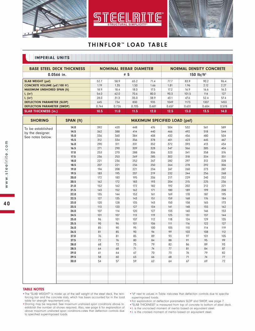
To be established by the designer. See notes below.
SHORING SPAN (ft) MAXIMUM SPECIFIED LOAD (psf)
NORMAL DENSITY CONCRETE
150 lb/ft3
BASE STEEL DECK THICKNESS
0.0566 in.
NOMINAL REBAR DIAMETER
# 5
IMPERIAL UNITS
•The "SLAB WEIGHT" is made up of the self weight of the steel deck, the rein-forcing bar and the concrete slab, which has been accounted for in the load table for strength requirement only.
•Shoring may be required. See maximum unshored span conditions above to establish the number of shores required. Also, see page 6 for explanation of above maximum unshored span conditions.cates that deflection controls due to specified superimposed loads.
•"d" next to values in Table indicates that deflection controls due to specifiesuperimposed loads.
•For explanation of deflection parameters SLDP and SWDP, see page 7.•"SLAB THICKNESS" is measured from top of concrete to bottom of steel deck.•Iu is the uncracked moment of inertia based on equivalent steel.•Ic is the cracked moment of inertia based on equivalent steel.
TABLE NOTES
SLAB WEIGHT (psf) 52.7 58.9 65.2 71.4 77.7 83.9 90.2 96.4CONCRETE VOLUME (yd3/100 ft2) 1.19 1.35 1.50 1.66 1.81 1.96 2.12 2.27MAXIMUM UNSHORED SPAN (ft) 18.9 18.4 18.0 17.5 17.2 16.9 16.6 16.3Iu (in4) 54.0 62.0 70.6 80.0 90.3 101.5 114 127Ic (in4) 28.0 31.3 35.0 38.9 43.1 47.6 52.4 57.4DEFLECTION PARAMETER (SLDP) 645 734 830 935 1049 1173 1307 1453DEFLECTION PARAMETER (SWDP) 0.744 0.726 0.705 0.681 0.657 0.631 0.604 0.578
SLAB THICKNESS (in.) 10.5 11.0 11.5 12.0 12.5 13.0 13.5 14.0
14.0 392 420 448 476 504 532 561 58914.5 362 388 414 440 466 492 518 54415.0 336 360 384 408 432 456 480 50415.5 312 334 356 378 401 423 445 46716.0 290 311 331 352 372 393 413 43416.5 271 290 309 328 347 366 385 40417.0 253 270 288 306 323 341 358 37617.5 236 253 269 285 302 318 334 35118.0 221 236 252 267 282 297 312 32818.5 207 221 236 250 264 278 292 30619.0 194 208 221 234 247 260 273 28719.5 183 195 207 219 232 244 256 26820.0 172 183 195 206 217 229 240 25220.5 162 172 183 193 204 215 225 23621.0 152 162 172 182 192 202 212 22121.5 143 152 162 171 180 189 199 20822.0 135 144 152 161 169 178 187 19522.5 127 135 143 151 159 168 176 18423.0 120 128 135 143 150 158 165 17323.5 113 120 127 134 141 148 155 16224.0 107 114 120 127 133 140 146 15324.5 101 107 113 119 125 131 137 14425.0 96 101 107 112 118 124 129 13525.5 90 96 101 106 111 116 122 12726.0 85 90 95 100 105 110 114 11926.5 81 85 90 94 99 103 108 11227.0 76 81 85 89 93 97 101 10527.5 72 76 80 84 88 91 95 9928.0 68 72 75 79 82 86 89 9328.5 64 68 71 74 77 81 84 8729.0 61 64 67 70 73 76 79 8229.5 58 60 63 66 68 71 74 7730.0 54 57 59 62 64 67 69 72
THINFLOR ™ LOAD TABLE
40
ww
w.s
tee
lrit
e.c
om
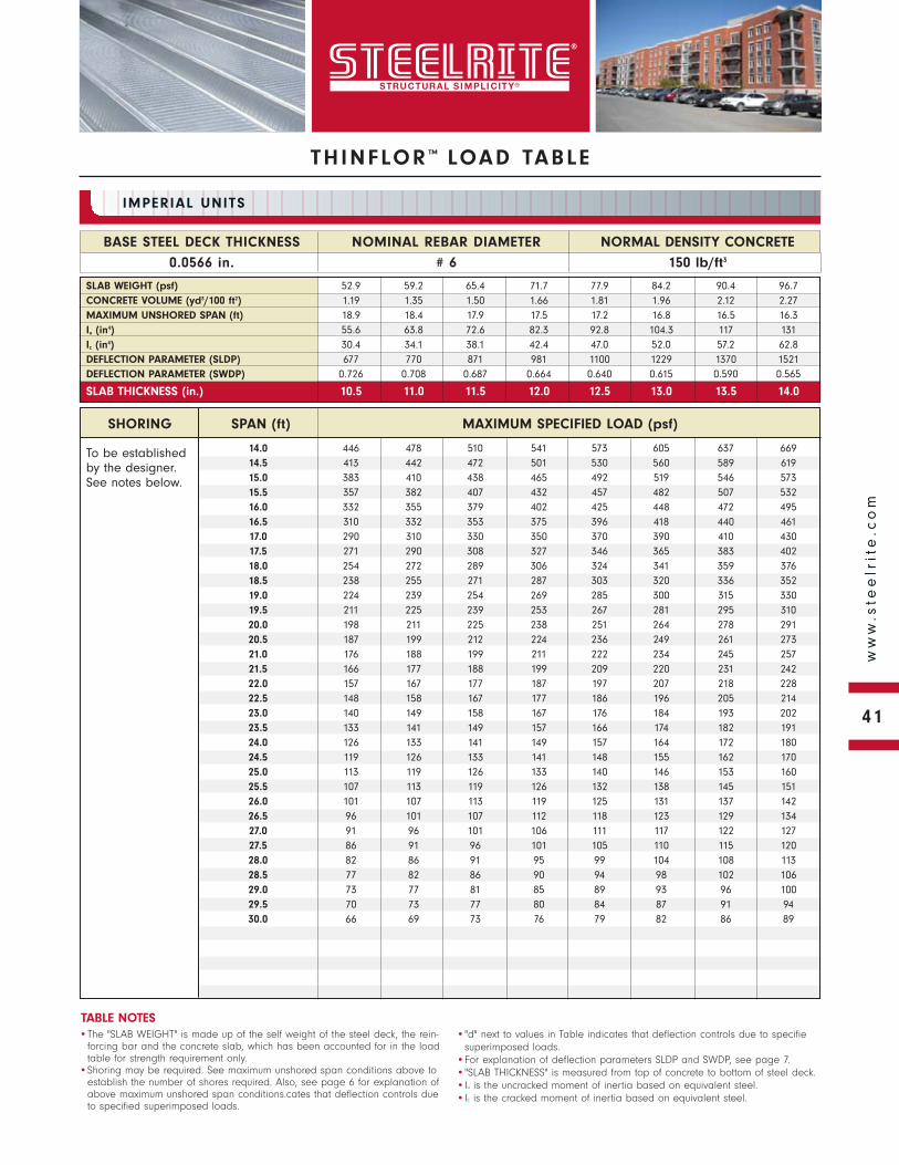
THINFLOR ™ LOAD TABLE
To be established by the designer. See notes below.
NORMAL DENSITY CONCRETE
150 lb/ft3
BASE STEEL DECK THICKNESS
0.0566 in.
NOMINAL REBAR DIAMETER
# 6
IMPERIAL UNITS
•The "SLAB WEIGHT" is made up of the self weight of the steel deck, the rein-forcing bar and the concrete slab, which has been accounted for in the load table for strength requirement only.
•Shoring may be required. See maximum unshored span conditions above to establish the number of shores required. Also, see page 6 for explanation of above maximum unshored span conditions.cates that deflection controls due to specified superimposed loads.
•"d" next to values in Table indicates that deflection controls due to specifiesuperimposed loads.
•For explanation of deflection parameters SLDP and SWDP, see page 7.•"SLAB THICKNESS" is measured from top of concrete to bottom of steel deck.•Iu is the uncracked moment of inertia based on equivalent steel.•Ic is the cracked moment of inertia based on equivalent steel.
TABLE NOTES
SLAB WEIGHT (psf) 52.9 59.2 65.4 71.7 77.9 84.2 90.4 96.7CONCRETE VOLUME (yd3/100 ft2) 1.19 1.35 1.50 1.66 1.81 1.96 2.12 2.27MAXIMUM UNSHORED SPAN (ft) 18.9 18.4 17.9 17.5 17.2 16.8 16.5 16.3Iu (in4) 55.6 63.8 72.6 82.3 92.8 104.3 117 131Ic (in4) 30.4 34.1 38.1 42.4 47.0 52.0 57.2 62.8DEFLECTION PARAMETER (SLDP) 677 770 871 981 1100 1229 1370 1521DEFLECTION PARAMETER (SWDP) 0.726 0.708 0.687 0.664 0.640 0.615 0.590 0.565
SLAB THICKNESS (in.) 10.5 11.0 11.5 12.0 12.5 13.0 13.5 14.0
SHORING SPAN (ft) MAXIMUM SPECIFIED LOAD (psf)
14.0 446 478 510 541 573 605 637 66914.5 413 442 472 501 530 560 589 61915.0 383 410 438 465 492 519 546 57315.5 357 382 407 432 457 482 507 53216.0 332 355 379 402 425 448 472 49516.5 310 332 353 375 396 418 440 46117.0 290 310 330 350 370 390 410 43017.5 271 290 308 327 346 365 383 40218.0 254 272 289 306 324 341 359 37618.5 238 255 271 287 303 320 336 35219.0 224 239 254 269 285 300 315 33019.5 211 225 239 253 267 281 295 31020.0 198 211 225 238 251 264 278 29120.5 187 199 212 224 236 249 261 27321.0 176 188 199 211 222 234 245 25721.5 166 177 188 199 209 220 231 24222.0 157 167 177 187 197 207 218 22822.5 148 158 167 177 186 196 205 21423.0 140 149 158 167 176 184 193 20223.5 133 141 149 157 166 174 182 19124.0 126 133 141 149 157 164 172 18024.5 119 126 133 141 148 155 162 17025.0 113 119 126 133 140 146 153 16025.5 107 113 119 126 132 138 145 15126.0 101 107 113 119 125 131 137 14226.5 96 101 107 112 118 123 129 13427.0 91 96 101 106 111 117 122 12727.5 86 91 96 101 105 110 115 12028.0 82 86 91 95 99 104 108 11328.5 77 82 86 90 94 98 102 10629.0 73 77 81 85 89 93 96 10029.5 70 73 77 80 84 87 91 9430.0 66 69 73 76 79 82 86 89
41
ww
w.s
tee
lrit
e.c
om
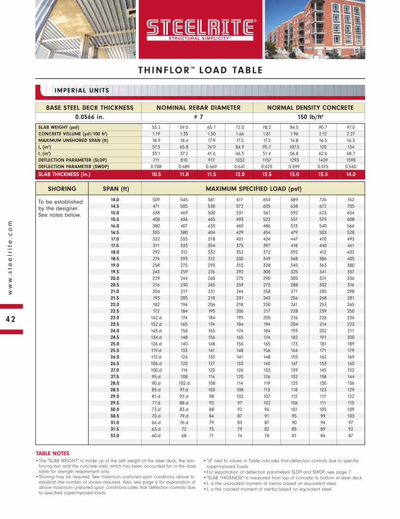
To be established by the designer. See notes below.
SHORING SPAN (ft) MAXIMUM SPECIFIED LOAD (psf)
NORMAL DENSITY CONCRETE
150 lb/ft3
BASE STEEL DECK THICKNESS
0.0566 in.
NOMINAL REBAR DIAMETER
# 7
IMPERIAL UNITS
•The "SLAB WEIGHT" is made up of the self weight of the steel deck, the rein-forcing bar and the concrete slab, which has been accounted for in the load table for strength requirement only.
•Shoring may be required. See maximum unshored span conditions above to establish the number of shores required. Also, see page 6 for explanation of above maximum unshored span conditions.cates that deflection controls due to specified superimposed loads.
•"d" next to values in Table indicates that deflection controls due to specifiesuperimposed loads.
•For explanation of deflection parameters SLDP and SWDP, see page 7.•"SLAB THICKNESS" is measured from top of concrete to bottom of steel deck.•Iu is the uncracked moment of inertia based on equivalent steel.•Ic is the cracked moment of inertia based on equivalent steel.
TABLE NOTES
SLAB WEIGHT (psf) 53.2 59.5 65.7 72.0 78.2 84.5 90.7 97.0CONCRETE VOLUME (yd3/100 ft2) 1.19 1.35 1.50 1.66 1.81 1.96 2.12 2.27MAXIMUM UNSHORED SPAN (ft) 18.9 18.4 17.9 17.5 17.2 16.8 16.5 16.3Iu (in4) 57.3 65.8 74.9 84.9 95.7 107.5 120 134Ic (in4) 33.1 37.2 41.6 46.3 51.4 56.8 62.6 68.7DEFLECTION PARAMETER (SLDP) 711 810 917 1032 1157 1293 1439 1598DEFLECTION PARAMETER (SWDP) 0.708 0.689 0.669 0.647 0.623 0.599 0.575 0.550
SLAB THICKNESS (in.) 10.5 11.0 11.5 12.0 12.5 13.0 13.5 14.0
14.0 509 545 581 617 653 689 726 76214.5 471 505 538 572 605 638 672 70515.0 438 469 500 531 561 592 623 65415.5 408 436 465 493 522 551 579 60816.0 380 407 433 460 486 513 540 56616.5 355 380 404 429 454 479 503 52817.0 332 355 378 401 424 447 470 49317.5 311 333 354 375 397 418 440 46118.0 292 312 332 352 372 392 412 43218.5 274 293 312 330 349 368 386 40519.0 258 275 293 310 328 345 363 38019.5 243 259 276 292 308 325 341 35720.0 229 244 260 275 290 305 321 33620.5 216 230 245 259 273 288 302 31621.0 204 217 231 244 258 271 285 29821.5 193 205 218 231 243 256 268 28122.0 182 194 206 218 230 241 253 26522.5 172 184 195 206 217 228 239 25023.0 162.d 174 184 195 205 216 226 23623.5 152.d 165 174 184 194 204 214 22324.0 143.d 156 165 174 184 193 202 21124.5 134.d 148 156 165 174 182 191 20025.0 126.d 140 148 156 165 173 181 18925.5 119.d 133 141 148 156 164 171 17926.0 112.d 126 133 141 148 155 162 16926.5 106.d 120 127 133 140 147 153 16027.0 100.d 114 120 126 133 139 145 15227.5 95.d 108 114 120 126 132 138 14428.0 90.d 102.d 108 114 119 125 130 13628.5 85.d 97.d 103 108 113 118 123 12929.0 81.d 92.d 98 102 107 112 117 12229.5 77.d 88.d 93 97 102 106 111 11530.0 73.d 83.d 88 92 96 101 105 10930.5 70.d 79.d 84 87 91 95 99 10331.0 66.d 76.d 79 83 87 90 94 9731.5 63.d 72 75 79 82 85 89 9232.0 60.d 68 71 74 78 81 84 87
THINFLOR ™ LOAD TABLE
42
ww
w.s
tee
lrit
e.c
om
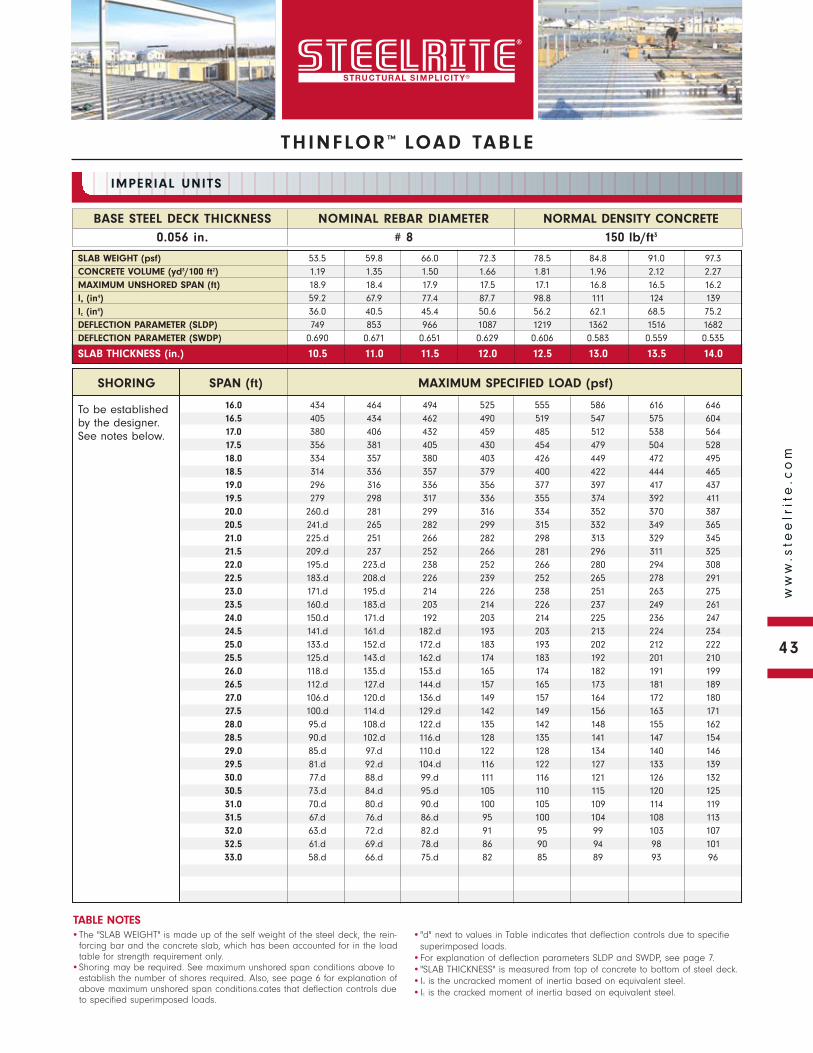
THINFLOR ™ LOAD TABLE
To be established by the designer. See notes below.
NORMAL DENSITY CONCRETE
150 lb/ft3
BASE STEEL DECK THICKNESS
0.056 in.
NOMINAL REBAR DIAMETER
# 8
IMPERIAL UNITS
•The "SLAB WEIGHT" is made up of the self weight of the steel deck, the rein-forcing bar and the concrete slab, which has been accounted for in the load table for strength requirement only.
•Shoring may be required. See maximum unshored span conditions above to establish the number of shores required. Also, see page 6 for explanation of above maximum unshored span conditions.cates that deflection controls due to specified superimposed loads.
•"d" next to values in Table indicates that deflection controls due to specifiesuperimposed loads.
•For explanation of deflection parameters SLDP and SWDP, see page 7.•"SLAB THICKNESS" is measured from top of concrete to bottom of steel deck.•Iu is the uncracked moment of inertia based on equivalent steel.•Ic is the cracked moment of inertia based on equivalent steel.
TABLE NOTES
SLAB WEIGHT (psf) 53.5 59.8 66.0 72.3 78.5 84.8 91.0 97.3CONCRETE VOLUME (yd3/100 ft2) 1.19 1.35 1.50 1.66 1.81 1.96 2.12 2.27MAXIMUM UNSHORED SPAN (ft) 18.9 18.4 17.9 17.5 17.1 16.8 16.5 16.2Iu (in4) 59.2 67.9 77.4 87.7 98.8 111 124 139Ic (in4) 36.0 40.5 45.4 50.6 56.2 62.1 68.5 75.2DEFLECTION PARAMETER (SLDP) 749 853 966 1087 1219 1362 1516 1682DEFLECTION PARAMETER (SWDP) 0.690 0.671 0.651 0.629 0.606 0.583 0.559 0.535
SLAB THICKNESS (in.) 10.5 11.0 11.5 12.0 12.5 13.0 13.5 14.0
SHORING SPAN (ft) MAXIMUM SPECIFIED LOAD (psf)
16.0 434 464 494 525 555 586 616 64616.5 405 434 462 490 519 547 575 60417.0 380 406 432 459 485 512 538 56417.5 356 381 405 430 454 479 504 52818.0 334 357 380 403 426 449 472 49518.5 314 336 357 379 400 422 444 46519.0 296 316 336 356 377 397 417 43719.5 279 298 317 336 355 374 392 41120.0 260.d 281 299 316 334 352 370 38720.5 241.d 265 282 299 315 332 349 36521.0 225.d 251 266 282 298 313 329 34521.5 209.d 237 252 266 281 296 311 32522.0 195.d 223.d 238 252 266 280 294 30822.5 183.d 208.d 226 239 252 265 278 29123.0 171.d 195.d 214 226 238 251 263 27523.5 160.d 183.d 203 214 226 237 249 26124.0 150.d 171.d 192 203 214 225 236 24724.5 141.d 161.d 182.d 193 203 213 224 23425.0 133.d 152.d 172.d 183 193 202 212 22225.5 125.d 143.d 162.d 174 183 192 201 21026.0 118.d 135.d 153.d 165 174 182 191 19926.5 112.d 127.d 144.d 157 165 173 181 18927.0 106.d 120.d 136.d 149 157 164 172 18027.5 100.d 114.d 129.d 142 149 156 163 17128.0 95.d 108.d 122.d 135 142 148 155 16228.5 90.d 102.d 116.d 128 135 141 147 15429.0 85.d 97.d 110.d 122 128 134 140 14629.5 81.d 92.d 104.d 116 122 127 133 13930.0 77.d 88.d 99.d 111 116 121 126 13230.5 73.d 84.d 95.d 105 110 115 120 12531.0 70.d 80.d 90.d 100 105 109 114 11931.5 67.d 76.d 86.d 95 100 104 108 11332.0 63.d 72.d 82.d 91 95 99 103 10732.5 61.d 69.d 78.d 86 90 94 98 10133.0 58.d 66.d 75.d 82 85 89 93 96
43
ww
w.s
tee
lrit
e.c
om
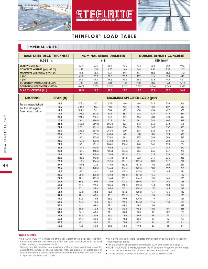
To be established by the designer. See notes below.
SHORING SPAN (ft) MAXIMUM SPECIFIED LOAD (psf)
NORMAL DENSITY CONCRETE
150 lb/ft3
BASE STEEL DECK THICKNESS
0.056 in.
NOMINAL REBAR DIAMETER
# 9
IMPERIAL UNITS
•The "SLAB WEIGHT" is made up of the self weight of the steel deck, the rein-forcing bar and the concrete slab, which has been accounted for in the load table for strength requirement only.
•Shoring may be required. See maximum unshored span conditions above to establish the number of shores required. Also, see page 6 for explanation of above maximum unshored span conditions.cates that deflection controls due to specified superimposed loads.
•"d" next to values in Table indicates that deflection controls due to specifiesuperimposed loads.
•For explanation of deflection parameters SLDP and SWDP, see page 7.•"SLAB THICKNESS" is measured from top of concrete to bottom of steel deck.•Iu is the uncracked moment of inertia based on equivalent steel.•Ic is the cracked moment of inertia based on equivalent steel.
TABLE NOTES
SLAB WEIGHT (psf) 53.9 60.1 66.4 72.6 78.9 85.1 91.4 97.6CONCRETE VOLUME (yd3/100 ft2) 1.19 1.35 1.50 1.66 1.81 1.96 2.12 2.27MAXIMUM UNSHORED SPAN (ft) 18.8 18.3 17.9 17.5 17.1 16.8 16.5 16.2Iu (in4) 61.1 70.2 80.0 90.7 102 115 128 143Ic (in4) 39.0 44.0 49.3 55.0 61.2 67.8 74.7 82.1DEFLECTION PARAMETER (SLDP) 788 898 1018 1146 1285 1436 1598 1772DEFLECTION PARAMETER (SWDP) 0.672 0.653 0.632 0.611 0.589 0.566 0.543 0.520
SLAB THICKNESS (in.) 10.5 11.0 11.5 12.0 12.5 13.0 13.5 14.0
18.0 375.d 407 433 460 486 513 539 56618.5 346.d 383 408 432 457 482 507 53219.0 319.d 361 384 407 430 454 477 50019.5 295.d 337.d 362 384 406 427 449 47120.0 274.d 312.d 342 362 383 403 424 44420.5 254.d 290.d 323 342 361 381 400 41921.0 236.d 269.d 305.d 323 342 360 378 39621.5 220.d 251.d 284.d 306 323 340 357 37522.0 206.d 234.d 265.d 290 306 322 338 35422.5 192.d 219.d 248.d 275 290 305 320 33623.0 180.d 205.d 232.d 261 275 289 304 31823.5 169.d 192.d 218.d 245.d 261 274 288 30224.0 158.d 181.d 204.d 230.d 248 261 273 28624.5 149.d 170.d 192.d 217.d 235 247 260 27225.0 140.d 160.d 181.d 204.d 224 235 247 25825.5 132.d 150.d 170.d 192.d 213 223 234 24526.0 125.d 142.d 161.d 181.d 202 213 223 23326.5 118.d 134.d 152.d 171.d 192.d 202 212 22227.0 111.d 127.d 144.d 162.d 181.d 192 202 21127.5 105.d 120.d 136.d 153.d 172.d 183 192 20128.0 100.d 114.d 129.d 145.d 163.d 174 183 19128.5 95.d 108.d 122.d 138.d 154.d 166 174 18229.0 90.d 102.d 116.d 131.d 146.d 158 166 17329.5 85.d 97.d 110.d 124.d 139.d 151 158 16530.0 81.d 92.d 105.d 118.d 132.d 144 150 15730.5 77.d 88.d 100.d 112.d 126.d 137 143 14931.0 73.d 84.d 95.d 107.d 120.d 131 136 14231.5 70.d 80.d 90.d 102.d 114.d 124 130 13532.0 67.d 76.d 86.d 97.d 109.d 119 124 12932.5 64.d 73.d 82.d 93.d 104.d 113 118 12333.0 61.d 69.d 79.d 89.d 99.d 108 112 11733.5 58.d 66.d 75.d 85.d 95.d 103 107 11134.0 56.d 63.d 72.d 81.d 91.d 98 102 10634.5 53.d 61.d 69.d 78.d 87.d 93 97 10135.0 51.d 58.d 66.d 74.d 83.d 89 92 9635.5 49.d 56.d 63.d 71.d 80.d 84 88 9136.0 47.d 53.d 61.d 68.d 77.d 80 83 87
THINFLOR ™ LOAD TABLE
44
ww
w.s
tee
lrit
e.c
om
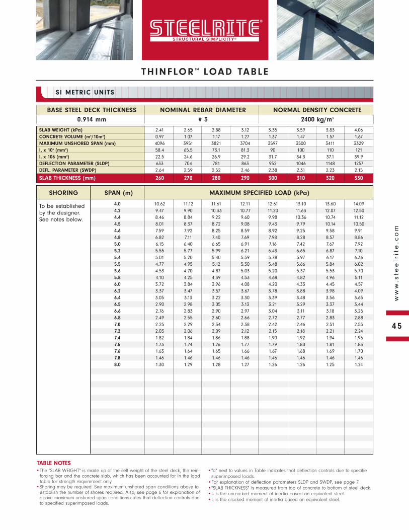
THINFLOR ™ LOAD TABLE
To be established by the designer. See notes below.
NORMAL DENSITY CONCRETE
2400 kg/m3
BASE STEEL DECK THICKNESS
0.914 mm
NOMINAL REBAR DIAMETER
# 3
SI METRIC UNITS
•The "SLAB WEIGHT" is made up of the self weight of the steel deck, the rein-forcing bar and the concrete slab, which has been accounted for in the load table for strength requirement only.
•Shoring may be required. See maximum unshored span conditions above to establish the number of shores required. Also, see page 6 for explanation of above maximum unshored span conditions.cates that deflection controls due to specified superimposed loads.
•"d" next to values in Table indicates that deflection controls due to specifiesuperimposed loads.
•For explanation of deflection parameters SLDP and SWDP, see page 7.•"SLAB THICKNESS" is measured from top of concrete to bottom of steel deck.•Iu is the uncracked moment of inertia based on equivalent steel.•Ic is the cracked moment of inertia based on equivalent steel.
TABLE NOTES
SLAB WEIGHT (kPa) 2.41 2.65 2.88 3.12 3.35 3.59 3.83 4.06CONCRETE VOLUME (m3/10m2) 0.97 1.07 1.17 1.27 1.37 1.47 1.57 1.67MAXIMUM UNSHORED SPAN (mm) 4096 3951 3821 3704 3597 3500 3411 3329Iu x 106 (mm4) 58.4 65.5 73.1 81.3 90 100 110 121Ic x 106 (mm4) 22.5 24.6 26.9 29.2 31.7 34.3 37.1 39.9DEFLECTION PARAMETER (SLDP) 633 704 781 863 952 1046 1148 1257DEFL. PARAMETER (SWDP) 2.64 2.59 2.52 2.46 2.38 2.31 2.23 2.15
SLAB THICKNESS (mm) 260 270 280 290 300 310 320 330
SHORING SPAN (m) MAXIMUM SPECIFIED LOAD (kPa)
4.0 10.62 11.12 11.61 12.11 12.61 13.10 13.60 14.094.2 9.47 9.90 10.33 10.77 11.20 11.63 12.07 12.504.4 8.46 8.84 9.22 9.60 9.98 10.36 10.74 11.124.5 8.01 8.37 8.72 9.08 9.43 9.79 10.14 10.504.6 7.59 7.92 8.25 8.59 8.92 9.25 9.58 9.914.8 6.82 7.11 7.40 7.69 7.98 8.28 8.57 8.865.0 6.15 6.40 6.65 6.91 7.16 7.42 7.67 7.925.2 5.55 5.77 5.99 6.21 6.43 6.65 6.87 7.105.4 5.01 5.20 5.40 5.59 5.78 5.97 6.17 6.365.5 4.77 4.95 5.12 5.30 5.48 5.66 5.84 6.025.6 4.53 4.70 4.87 5.03 5.20 5.37 5.53 5.705.8 4.10 4.25 4.39 4.53 4.68 4.82 4.96 5.116.0 3.72 3.84 3.96 4.08 4.20 4.33 4.45 4.576.2 3.37 3.47 3.57 3.67 3.78 3.88 3.98 4.096.4 3.05 3.13 3.22 3.30 3.39 3.48 3.56 3.656.5 2.90 2.98 3.05 3.13 3.21 3.29 3.37 3.446.6 2.76 2.83 2.90 2.97 3.04 3.11 3.18 3.256.8 2.49 2.55 2.60 2.66 2.72 2.77 2.83 2.887.0 2.25 2.29 2.34 2.38 2.42 2.46 2.51 2.557.2 2.03 2.06 2.09 2.12 2.15 2.18 2.21 2.247.4 1.82 1.84 1.86 1.88 1.90 1.92 1.94 1.967.5 1.73 1.74 1.76 1.77 1.79 1.80 1.81 1.837.6 1.63 1.64 1.65 1.66 1.67 1.68 1.69 1.707.8 1.46 1.46 1.46 1.46 1.46 1.46 1.46 1.468.0 1.30 1.29 1.28 1.27 1.26 1.26 1.25 1.24
45
ww
w.s
tee
lrit
e.c
om
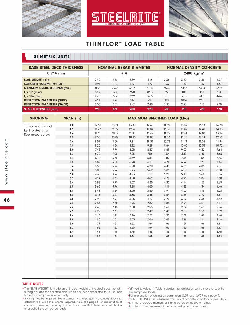
To be established by the designer. See notes below.
SHORING SPAN (m) MAXIMUM SPECIFIED LOAD (kPa)
NORMAL DENSITY CONCRETE
2400 kg/m3
BASE STEEL DECK THICKNESS
0.914 mm
NOMINAL REBAR DIAMETER
# 4
SI METRIC UNITS
•The "SLAB WEIGHT" is made up of the self weight of the steel deck, the rein-forcing bar and the concrete slab, which has been accounted for in the load table for strength requirement only.
•Shoring may be required. See maximum unshored span conditions above to establish the number of shores required. Also, see page 6 for explanation of above maximum unshored span conditions.cates that deflection controls due to specified superimposed loads.
•"d" next to values in Table indicates that deflection controls due to specifiesuperimposed loads.
•For explanation of deflection parameters SLDP and SWDP, see page 7.•"SLAB THICKNESS" is measured from top of concrete to bottom of steel deck.•Iu is the uncracked moment of inertia based on equivalent steel.•Ic is the cracked moment of inertia based on equivalent steel.
TABLE NOTES
SLAB WEIGHT (kPa) 2.42 2.66 2.89 3.13 3.36 3.60 3.83 4.07CONCRETE VOLUME (m3/10m2) 0.97 1.07 1.17 1.27 1.37 1.47 1.57 1.67MAXIMUM UNSHORED SPAN (mm) 4091 3947 3817 3700 3594 3497 3408 3326Iu x 106 (mm4) 59.9 67.2 75.0 83.3 92 102 113 124Ic x 106 (mm4) 25.0 27.4 29.9 32.5 35.3 38.3 41.3 44.6DEFLECTION PARAMETER (SLDP) 663 739 819 905 997 1096 1201 1315DEFLECTION PARAMETER (SWDP) 2.58 2.53 2.47 2.40 2.33 2.26 2.18 2.10
SLAB THICKNESS (mm) 260 270 280 290 300 310 320 330
4.0 12.61 13.21 13.80 14.40 14.99 15.59 16.18 16.784.2 11.27 11.79 12.32 12.84 13.36 13.89 14.41 14.934.4 10.11 10.57 11.03 11.49 11.95 12.41 12.88 13.344.5 9.58 10.02 10.45 10.88 11.32 11.75 12.18 12.624.6 9.09 9.50 9.91 10.31 10.72 11.13 11.54 11.944.8 8.20 8.56 8.92 9.28 9.64 10.00 10.36 10.725.0 7.42 7.74 8.05 8.37 8.69 9.00 9.32 9.645.2 6.72 7.00 7.28 7.56 7.84 8.12 8.40 8.685.4 6.10 6.35 6.59 6.84 7.09 7.34 7.58 7.835.5 5.82 6.05 6.28 6.51 6.74 6.97 7.21 7.445.6 5.55 5.76 5.98 6.20 6.41 6.63 6.85 7.075.8 5.05 5.24 5.43 5.62 5.81 6.00 6.19 6.386.0 4.60 4.76 4.93 5.10 5.26 5.43 5.60 5.766.2 4.19 4.33 4.48 4.62 4.77 4.91 5.06 5.206.4 3.82 3.95 4.07 4.20 4.32 4.44 4.57 4.696.5 3.65 3.76 3.88 4.00 4.11 4.23 4.34 4.466.6 3.48 3.59 3.70 3.80 3.91 4.02 4.13 4.236.8 3.18 3.27 3.36 3.45 3.54 3.63 3.72 3.817.0 2.90 2.97 3.05 3.12 3.20 3.27 3.35 3.427.2 2.64 2.70 2.76 2.82 2.88 2.95 3.01 3.077.4 2.40 2.45 2.50 2.55 2.60 2.64 2.69 2.747.5 2.29 2.33 2.37 2.42 2.46 2.50 2.55 2.597.6 2.18 2.22 2.26 2.29 2.33 2.37 2.40 2.447.8 1.98 2.01 2.03 2.06 2.08 2.11 2.14 2.168.0 1.79 1.81 1.82 1.84 1.86 1.87 1.89 1.918.2 1.62 1.62 1.63 1.64 1.65 1.65 1.66 1.678.4 1.46 1.45 1.45 1.45 1.45 1.45 1.45 1.458.5 1.38 1.37 1.37 1.36 1.36 1.35 1.35 1.34
THINFLOR ™ LOAD TABLE
46
ww
w.s
tee
lrit
e.c
om
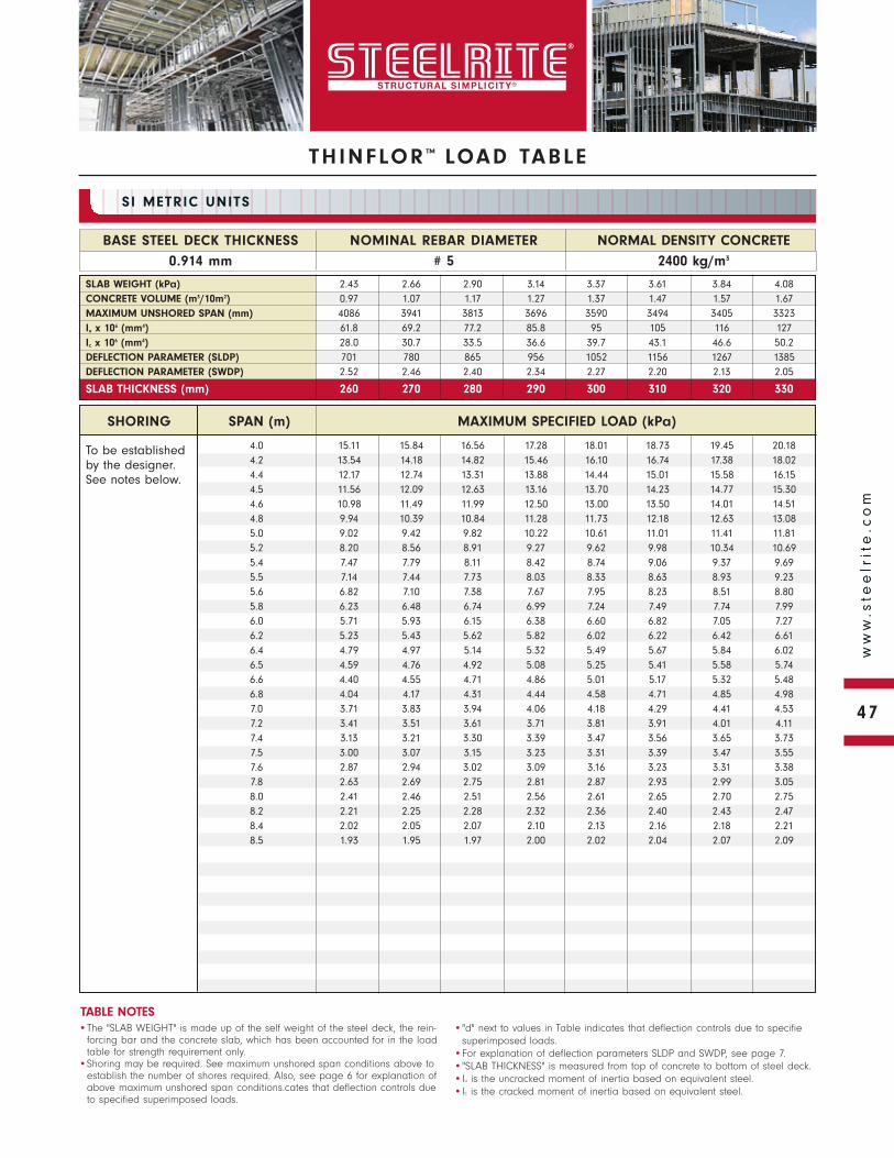
THINFLOR ™ LOAD TABLE
To be established by the designer. See notes below.
NORMAL DENSITY CONCRETE
2400 kg/m3
BASE STEEL DECK THICKNESS
0.914 mm
NOMINAL REBAR DIAMETER
# 5
SI METRIC UNITS
•The "SLAB WEIGHT" is made up of the self weight of the steel deck, the rein-forcing bar and the concrete slab, which has been accounted for in the load table for strength requirement only.
•Shoring may be required. See maximum unshored span conditions above to establish the number of shores required. Also, see page 6 for explanation of above maximum unshored span conditions.cates that deflection controls due to specified superimposed loads.
•"d" next to values in Table indicates that deflection controls due to specifiesuperimposed loads.
•For explanation of deflection parameters SLDP and SWDP, see page 7.•"SLAB THICKNESS" is measured from top of concrete to bottom of steel deck.•Iu is the uncracked moment of inertia based on equivalent steel.•Ic is the cracked moment of inertia based on equivalent steel.
TABLE NOTES
SLAB WEIGHT (kPa) 2.43 2.66 2.90 3.14 3.37 3.61 3.84 4.08CONCRETE VOLUME (m3/10m2) 0.97 1.07 1.17 1.27 1.37 1.47 1.57 1.67MAXIMUM UNSHORED SPAN (mm) 4086 3941 3813 3696 3590 3494 3405 3323Iu x 106 (mm4) 61.8 69.2 77.2 85.8 95 105 116 127Ic x 106 (mm4) 28.0 30.7 33.5 36.6 39.7 43.1 46.6 50.2DEFLECTION PARAMETER (SLDP) 701 780 865 956 1052 1156 1267 1385DEFLECTION PARAMETER (SWDP) 2.52 2.46 2.40 2.34 2.27 2.20 2.13 2.05
SLAB THICKNESS (mm) 260 270 280 290 300 310 320 330
SHORING SPAN (m) MAXIMUM SPECIFIED LOAD (kPa)
4.0 15.11 15.84 16.56 17.28 18.01 18.73 19.45 20.184.2 13.54 14.18 14.82 15.46 16.10 16.74 17.38 18.024.4 12.17 12.74 13.31 13.88 14.44 15.01 15.58 16.154.5 11.56 12.09 12.63 13.16 13.70 14.23 14.77 15.304.6 10.98 11.49 11.99 12.50 13.00 13.50 14.01 14.514.8 9.94 10.39 10.84 11.28 11.73 12.18 12.63 13.085.0 9.02 9.42 9.82 10.22 10.61 11.01 11.41 11.815.2 8.20 8.56 8.91 9.27 9.62 9.98 10.34 10.695.4 7.47 7.79 8.11 8.42 8.74 9.06 9.37 9.695.5 7.14 7.44 7.73 8.03 8.33 8.63 8.93 9.235.6 6.82 7.10 7.38 7.67 7.95 8.23 8.51 8.805.8 6.23 6.48 6.74 6.99 7.24 7.49 7.74 7.996.0 5.71 5.93 6.15 6.38 6.60 6.82 7.05 7.276.2 5.23 5.43 5.62 5.82 6.02 6.22 6.42 6.616.4 4.79 4.97 5.14 5.32 5.49 5.67 5.84 6.026.5 4.59 4.76 4.92 5.08 5.25 5.41 5.58 5.746.6 4.40 4.55 4.71 4.86 5.01 5.17 5.32 5.486.8 4.04 4.17 4.31 4.44 4.58 4.71 4.85 4.987.0 3.71 3.83 3.94 4.06 4.18 4.29 4.41 4.537.2 3.41 3.51 3.61 3.71 3.81 3.91 4.01 4.117.4 3.13 3.21 3.30 3.39 3.47 3.56 3.65 3.737.5 3.00 3.07 3.15 3.23 3.31 3.39 3.47 3.557.6 2.87 2.94 3.02 3.09 3.16 3.23 3.31 3.387.8 2.63 2.69 2.75 2.81 2.87 2.93 2.99 3.058.0 2.41 2.46 2.51 2.56 2.61 2.65 2.70 2.758.2 2.21 2.25 2.28 2.32 2.36 2.40 2.43 2.478.4 2.02 2.05 2.07 2.10 2.13 2.16 2.18 2.218.5 1.93 1.95 1.97 2.00 2.02 2.04 2.07 2.09
47
ww
w.s
tee
lrit
e.c
om
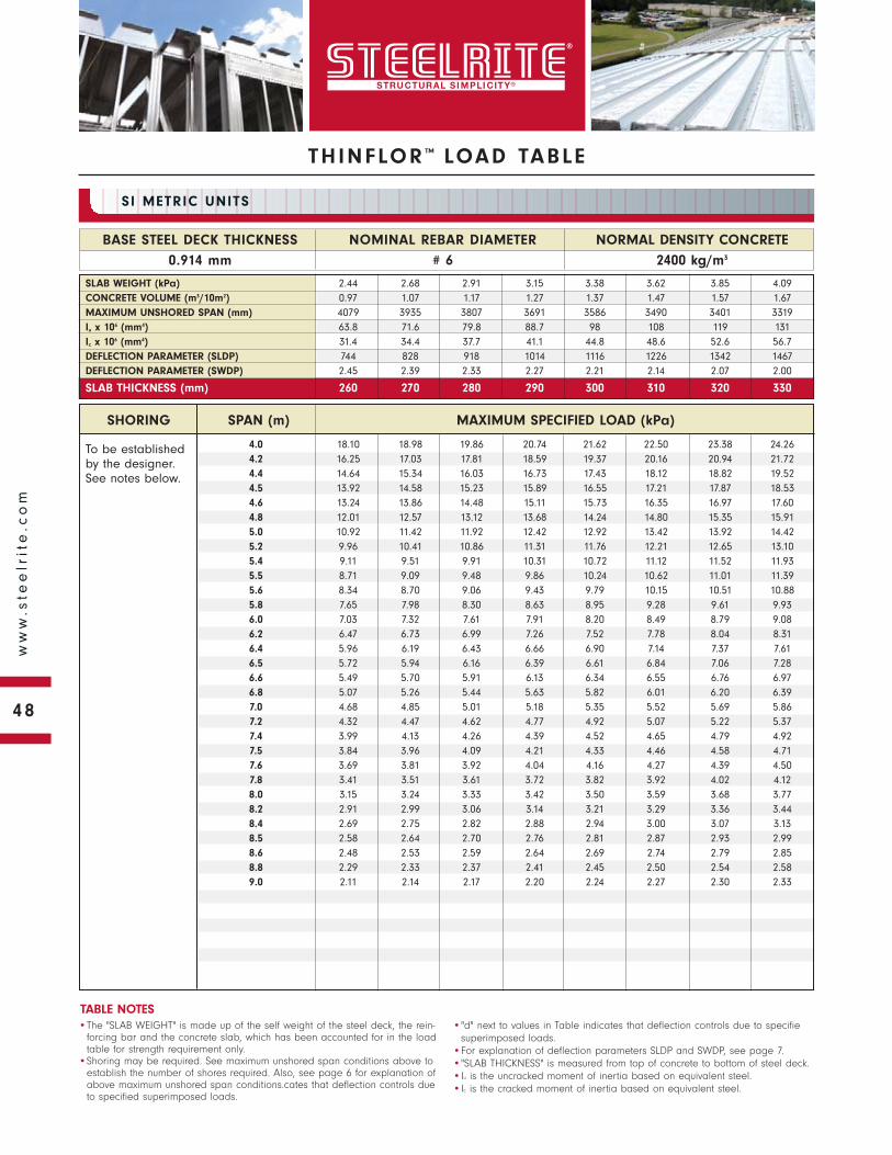
To be established by the designer. See notes below.
SHORING SPAN (m) MAXIMUM SPECIFIED LOAD (kPa)
NORMAL DENSITY CONCRETE
2400 kg/m3
BASE STEEL DECK THICKNESS
0.914 mm
NOMINAL REBAR DIAMETER
# 6
SI METRIC UNITS
•The "SLAB WEIGHT" is made up of the self weight of the steel deck, the rein-forcing bar and the concrete slab, which has been accounted for in the load table for strength requirement only.
•Shoring may be required. See maximum unshored span conditions above to establish the number of shores required. Also, see page 6 for explanation of above maximum unshored span conditions.cates that deflection controls due to specified superimposed loads.
•"d" next to values in Table indicates that deflection controls due to specifiesuperimposed loads.
•For explanation of deflection parameters SLDP and SWDP, see page 7.•"SLAB THICKNESS" is measured from top of concrete to bottom of steel deck.•Iu is the uncracked moment of inertia based on equivalent steel.•Ic is the cracked moment of inertia based on equivalent steel.
TABLE NOTES
SLAB WEIGHT (kPa) 2.44 2.68 2.91 3.15 3.38 3.62 3.85 4.09CONCRETE VOLUME (m3/10m2) 0.97 1.07 1.17 1.27 1.37 1.47 1.57 1.67MAXIMUM UNSHORED SPAN (mm) 4079 3935 3807 3691 3586 3490 3401 3319Iu x 106 (mm4) 63.8 71.6 79.8 88.7 98 108 119 131Ic x 106 (mm4) 31.4 34.4 37.7 41.1 44.8 48.6 52.6 56.7DEFLECTION PARAMETER (SLDP) 744 828 918 1014 1116 1226 1342 1467DEFLECTION PARAMETER (SWDP) 2.45 2.39 2.33 2.27 2.21 2.14 2.07 2.00
SLAB THICKNESS (mm) 260 270 280 290 300 310 320 330
TH INFLOR ™ LOAD TABLE
4.0 18.10 18.98 19.86 20.74 21.62 22.50 23.38 24.264.2 16.25 17.03 17.81 18.59 19.37 20.16 20.94 21.724.4 14.64 15.34 16.03 16.73 17.43 18.12 18.82 19.524.5 13.92 14.58 15.23 15.89 16.55 17.21 17.87 18.534.6 13.24 13.86 14.48 15.11 15.73 16.35 16.97 17.604.8 12.01 12.57 13.12 13.68 14.24 14.80 15.35 15.915.0 10.92 11.42 11.92 12.42 12.92 13.42 13.92 14.425.2 9.96 10.41 10.86 11.31 11.76 12.21 12.65 13.105.4 9.11 9.51 9.91 10.31 10.72 11.12 11.52 11.935.5 8.71 9.09 9.48 9.86 10.24 10.62 11.01 11.395.6 8.34 8.70 9.06 9.43 9.79 10.15 10.51 10.885.8 7.65 7.98 8.30 8.63 8.95 9.28 9.61 9.936.0 7.03 7.32 7.61 7.91 8.20 8.49 8.79 9.086.2 6.47 6.73 6.99 7.26 7.52 7.78 8.04 8.316.4 5.96 6.19 6.43 6.66 6.90 7.14 7.37 7.616.5 5.72 5.94 6.16 6.39 6.61 6.84 7.06 7.286.6 5.49 5.70 5.91 6.13 6.34 6.55 6.76 6.976.8 5.07 5.26 5.44 5.63 5.82 6.01 6.20 6.397.0 4.68 4.85 5.01 5.18 5.35 5.52 5.69 5.867.2 4.32 4.47 4.62 4.77 4.92 5.07 5.22 5.377.4 3.99 4.13 4.26 4.39 4.52 4.65 4.79 4.927.5 3.84 3.96 4.09 4.21 4.33 4.46 4.58 4.717.6 3.69 3.81 3.92 4.04 4.16 4.27 4.39 4.507.8 3.41 3.51 3.61 3.72 3.82 3.92 4.02 4.128.0 3.15 3.24 3.33 3.42 3.50 3.59 3.68 3.778.2 2.91 2.99 3.06 3.14 3.21 3.29 3.36 3.448.4 2.69 2.75 2.82 2.88 2.94 3.00 3.07 3.138.5 2.58 2.64 2.70 2.76 2.81 2.87 2.93 2.998.6 2.48 2.53 2.59 2.64 2.69 2.74 2.79 2.858.8 2.29 2.33 2.37 2.41 2.45 2.50 2.54 2.589.0 2.11 2.14 2.17 2.20 2.24 2.27 2.30 2.33
48
ww
w.s
tee
lrit
e.c
om
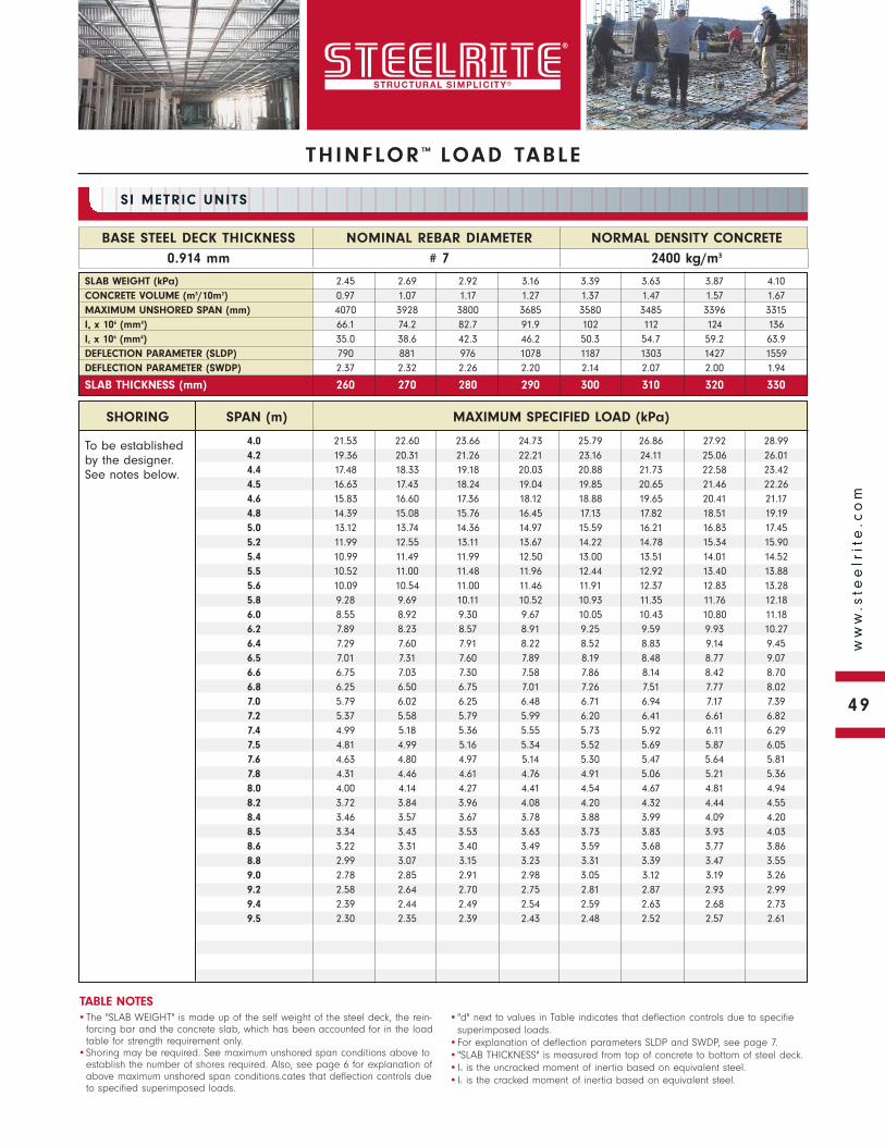
THINFLOR ™ LOAD TABLE
To be established by the designer. See notes below.
NORMAL DENSITY CONCRETE
2400 kg/m3
BASE STEEL DECK THICKNESS
0.914 mm
NOMINAL REBAR DIAMETER
# 7
SI METRIC UNITS
•The "SLAB WEIGHT" is made up of the self weight of the steel deck, the rein-forcing bar and the concrete slab, which has been accounted for in the load table for strength requirement only.
•Shoring may be required. See maximum unshored span conditions above to establish the number of shores required. Also, see page 6 for explanation of above maximum unshored span conditions.cates that deflection controls due to specified superimposed loads.
•"d" next to values in Table indicates that deflection controls due to specifiesuperimposed loads.
•For explanation of deflection parameters SLDP and SWDP, see page 7.•"SLAB THICKNESS" is measured from top of concrete to bottom of steel deck.•Iu is the uncracked moment of inertia based on equivalent steel.•Ic is the cracked moment of inertia based on equivalent steel.
TABLE NOTES
SLAB WEIGHT (kPa) 2.45 2.69 2.92 3.16 3.39 3.63 3.87 4.10CONCRETE VOLUME (m3/10m2) 0.97 1.07 1.17 1.27 1.37 1.47 1.57 1.67MAXIMUM UNSHORED SPAN (mm) 4070 3928 3800 3685 3580 3485 3396 3315Iu x 106 (mm4) 66.1 74.2 82.7 91.9 102 112 124 136Ic x 106 (mm4) 35.0 38.6 42.3 46.2 50.3 54.7 59.2 63.9DEFLECTION PARAMETER (SLDP) 790 881 976 1078 1187 1303 1427 1559DEFLECTION PARAMETER (SWDP) 2.37 2.32 2.26 2.20 2.14 2.07 2.00 1.94
SLAB THICKNESS (mm) 260 270 280 290 300 310 320 330
SHORING SPAN (m) MAXIMUM SPECIFIED LOAD (kPa)
4.0 21.53 22.60 23.66 24.73 25.79 26.86 27.92 28.994.2 19.36 20.31 21.26 22.21 23.16 24.11 25.06 26.014.4 17.48 18.33 19.18 20.03 20.88 21.73 22.58 23.424.5 16.63 17.43 18.24 19.04 19.85 20.65 21.46 22.264.6 15.83 16.60 17.36 18.12 18.88 19.65 20.41 21.174.8 14.39 15.08 15.76 16.45 17.13 17.82 18.51 19.195.0 13.12 13.74 14.36 14.97 15.59 16.21 16.83 17.455.2 11.99 12.55 13.11 13.67 14.22 14.78 15.34 15.905.4 10.99 11.49 11.99 12.50 13.00 13.51 14.01 14.525.5 10.52 11.00 11.48 11.96 12.44 12.92 13.40 13.885.6 10.09 10.54 11.00 11.46 11.91 12.37 12.83 13.285.8 9.28 9.69 10.11 10.52 10.93 11.35 11.76 12.186.0 8.55 8.92 9.30 9.67 10.05 10.43 10.80 11.186.2 7.89 8.23 8.57 8.91 9.25 9.59 9.93 10.276.4 7.29 7.60 7.91 8.22 8.52 8.83 9.14 9.456.5 7.01 7.31 7.60 7.89 8.19 8.48 8.77 9.076.6 6.75 7.03 7.30 7.58 7.86 8.14 8.42 8.706.8 6.25 6.50 6.75 7.01 7.26 7.51 7.77 8.027.0 5.79 6.02 6.25 6.48 6.71 6.94 7.17 7.397.2 5.37 5.58 5.79 5.99 6.20 6.41 6.61 6.827.4 4.99 5.18 5.36 5.55 5.73 5.92 6.11 6.297.5 4.81 4.99 5.16 5.34 5.52 5.69 5.87 6.057.6 4.63 4.80 4.97 5.14 5.30 5.47 5.64 5.817.8 4.31 4.46 4.61 4.76 4.91 5.06 5.21 5.368.0 4.00 4.14 4.27 4.41 4.54 4.67 4.81 4.948.2 3.72 3.84 3.96 4.08 4.20 4.32 4.44 4.558.4 3.46 3.57 3.67 3.78 3.88 3.99 4.09 4.208.5 3.34 3.43 3.53 3.63 3.73 3.83 3.93 4.038.6 3.22 3.31 3.40 3.49 3.59 3.68 3.77 3.868.8 2.99 3.07 3.15 3.23 3.31 3.39 3.47 3.559.0 2.78 2.85 2.91 2.98 3.05 3.12 3.19 3.269.2 2.58 2.64 2.70 2.75 2.81 2.87 2.93 2.999.4 2.39 2.44 2.49 2.54 2.59 2.63 2.68 2.739.5 2.30 2.35 2.39 2.43 2.48 2.52 2.57 2.61
49
ww
w.s
tee
lrit
e.c
om
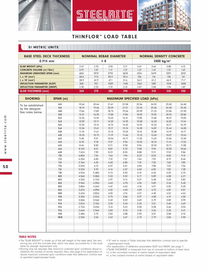
To be established by the designer. See notes below.
SHORING SPAN (m) MAXIMUM SPECIFIED LOAD (kPa)
NORMAL DENSITY CONCRETE
2400 kg/m3
BASE STEEL DECK THICKNESS
0.914 mm
NOMINAL REBAR DIAMETER
# 8
SI METRIC UNITS
•The "SLAB WEIGHT" is made up of the self weight of the steel deck, the rein-forcing bar and the concrete slab, which has been accounted for in the load table for strength requirement only.
•Shoring may be required. See maximum unshored span conditions above to establish the number of shores required. Also, see page 6 for explanation of above maximum unshored span conditions.cates that deflection controls due to specified superimposed loads.
•"d" next to values in Table indicates that deflection controls due to specifiesuperimposed loads.
•For explanation of deflection parameters SLDP and SWDP, see page 7.•"SLAB THICKNESS" is measured from top of concrete to bottom of steel deck.•Iu is the uncracked moment of inertia based on equivalent steel.•Ic is the cracked moment of inertia based on equivalent steel.
TABLE NOTES
SLAB WEIGHT (kPa) 2.47 2.70 2.94 3.17 3.41 3.64 3.88 4.12CONCRETE VOLUME (m3/10m2) 0.97 1.07 1.17 1.27 1.37 1.47 1.57 1.67MAXIMUM UNSHORED SPAN (mm) 4061 3919 3792 3678 3574 3479 3391 3310Iu x 106 (mm4) 68.6 77.0 85.9 95.4 106 116 128 141Ic x 106 (mm4) 38.9 42.9 47.1 51.6 56.3 61.2 66.3 71.7DEFLECTION PARAMETER (SLDP) 840 937 1039 1148 1264 1387 1518 1658DEFLECTION PARAMETER (SWDP) 2.30 2.25 2.19 2.13 2.07 2.00 1.94 1.87
SLAB THICKNESS (mm) 260 270 280 290 300 310 320 330
4.5 19.66 20.64 21.61 22.58 23.56 24.53 25.50 26.484.6 18.74 19.66 20.59 21.51 22.43 23.36 24.28 25.204.8 17.06 17.89 18.73 19.56 20.39 21.23 22.06 22.905.0 15.57 16.33 17.08 17.84 18.59 19.35 20.10 20.865.2 14.26 14.94 15.63 16.31 17.00 17.68 18.37 19.055.4 13.09 13.71 14.33 14.95 15.58 16.20 16.82 17.445.5 12.55 13.14 13.74 14.33 14.92 15.52 16.11 16.705.6 12.04 12.61 13.17 13.74 14.30 14.87 15.44 16.005.8 11.10 11.61 12.13 12.65 13.16 13.68 14.19 14.716.0 10.25 10.72 11.19 11.66 12.13 12.60 13.07 13.546.2 9.48 9.91 10.34 10.77 11.20 11.63 12.06 12.496.4 8.78 9.18 9.57 9.96 10.35 10.74 11.14 11.536.5 8.46 8.83 9.21 9.58 9.96 10.33 10.71 11.086.6 8.12d 8.51 8.87 9.22 9.58 9.94 10.30 10.666.8 7.42d 7.90 8.22 8.55 8.88 9.21 9.53 9.867.0 6.80d 7.34 7.64 7.94 8.23 8.53 8.83 9.137.2 6.25d 6.83 7.10 7.37 7.64 7.92 8.19 8.467.4 5.76d 6.35 6.60 6.85 7.10 7.35 7.60 7.857.5 5.53d 6.13 6.37 6.61 6.84 7.08 7.32 7.567.6 5.32d 5.92 6.14 6.37 6.60 6.82 7.05 7.287.8 4.92d 5.48d 5.72 5.93 6.13 6.34 6.55 6.758.0 4.56d 5.08d 5.33 5.52 5.71 5.89 6.08 6.278.2 4.23d 4.72d 4.97 5.14 5.31 5.48 5.65 5.828.4 3.94d 4.39d 4.63 4.78 4.94 5.09 5.24 5.408.5 3.80d 4.24d 4.47 4.62 4.76 4.91 5.05 5.208.6 3.67d 4.09d 4.32 4.45 4.59 4.73 4.87 5.018.8 3.42d 3.82d 4.02 4.15 4.27 4.40 4.52 4.649.0 3.20d 3.57d 3.75 3.86 3.97 4.08 4.19 4.309.2 3.00d 3.34d 3.49 3.59 3.69 3.79 3.89 3.999.4 2.81d 3.13d 3.25 3.34 3.43 3.51 3.60 3.699.5 2.72d 3.03d 3.14 3.22 3.30 3.38 3.46 3.559.6 2.64d 2.94d 3.03 3.10 3.18 3.26 3.33 3.419.8 2.48d 2.75 2.82 2.88 2.95 3.01 3.08 3.1510.0 2.33d 2.56 2.62 2.67 2.73 2.79 2.84 2.90
THINFLOR ™ LOAD TABLE
50
ww
w.s
tee
lrit
e.c
om
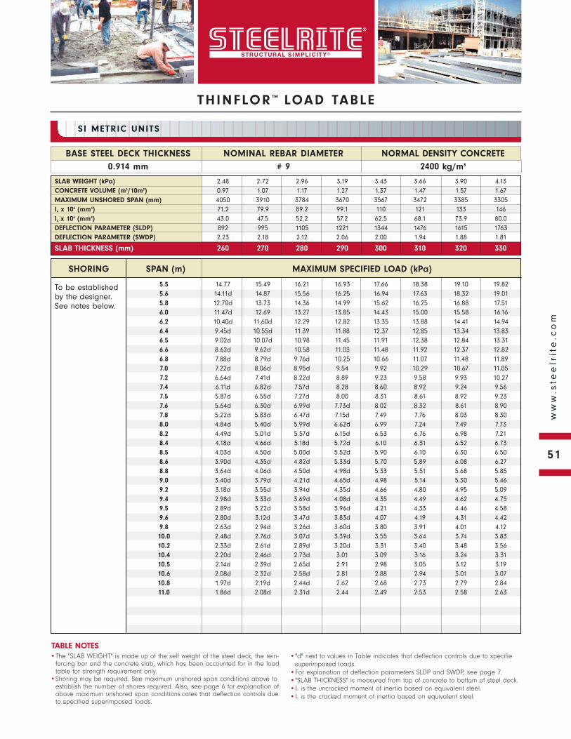
THINFLOR ™ LOAD TABLE
To be established by the designer. See notes below.
NORMAL DENSITY CONCRETE
2400 kg/m3
BASE STEEL DECK THICKNESS
0.914 mm
NOMINAL REBAR DIAMETER
# 9
SI METRIC UNITS
•The "SLAB WEIGHT" is made up of the self weight of the steel deck, the rein-forcing bar and the concrete slab, which has been accounted for in the load table for strength requirement only.
•Shoring may be required. See maximum unshored span conditions above to establish the number of shores required. Also, see page 6 for explanation of above maximum unshored span conditions.cates that deflection controls due to specified superimposed loads.
•"d" next to values in Table indicates that deflection controls due to specifiesuperimposed loads.
•For explanation of deflection parameters SLDP and SWDP, see page 7.•"SLAB THICKNESS" is measured from top of concrete to bottom of steel deck.•Iu is the uncracked moment of inertia based on equivalent steel.•Ic is the cracked moment of inertia based on equivalent steel.
TABLE NOTES
SLAB WEIGHT (kPa) 2.48 2.72 2.96 3.19 3.43 3.66 3.90 4.13CONCRETE VOLUME (m3/10m2) 0.97 1.07 1.17 1.27 1.37 1.47 1.57 1.67MAXIMUM UNSHORED SPAN (mm) 4050 3910 3784 3670 3567 3472 3385 3305Iu x 106 (mm4) 71.2 79.9 89.2 99.1 110 121 133 146Ic x 106 (mm4) 43.0 47.5 52.2 57.2 62.5 68.1 73.9 80.0DEFLECTION PARAMETER (SLDP) 892 995 1105 1221 1344 1476 1615 1763DEFLECTION PARAMETER (SWDP) 2.23 2.18 2.12 2.06 2.00 1.94 1.88 1.81
SLAB THICKNESS (mm) 260 270 280 290 300 310 320 330
SHORING SPAN (m) MAXIMUM SPECIFIED LOAD (kPa)
5.5 14.77 15.49 16.21 16.93 17.66 18.38 19.10 19.825.6 14.11d 14.87 15.56 16.25 16.94 17.63 18.32 19.015.8 12.70d 13.73 14.36 14.99 15.62 16.25 16.88 17.516.0 11.47d 12.69 13.27 13.85 14.43 15.00 15.58 16.166.2 10.40d 11.60d 12.29 12.82 13.35 13.88 14.41 14.946.4 9.45d 10.55d 11.39 11.88 12.37 12.85 13.34 13.836.5 9.02d 10.07d 10.98 11.45 11.91 12.38 12.84 13.316.6 8.62d 9.62d 10.58 11.03 11.48 11.92 12.37 12.826.8 7.88d 8.79d 9.76d 10.25 10.66 11.07 11.48 11.897.0 7.22d 8.06d 8.95d 9.54 9.92 10.29 10.67 11.057.2 6.64d 7.41d 8.22d 8.89 9.23 9.58 9.93 10.277.4 6.11d 6.82d 7.57d 8.28 8.60 8.92 9.24 9.567.5 5.87d 6.55d 7.27d 8.00 8.31 8.61 8.92 9.237.6 5.64d 6.30d 6.99d 7.73d 8.02 8.32 8.61 8.907.8 5.22d 5.83d 6.47d 7.15d 7.49 7.76 8.03 8.308.0 4.84d 5.40d 5.99d 6.62d 6.99 7.24 7.49 7.738.2 4.49d 5.01d 5.57d 6.15d 6.53 6.76 6.98 7.218.4 4.18d 4.66d 5.18d 5.72d 6.10 6.31 6.52 6.738.5 4.03d 4.50d 5.00d 5.52d 5.90 6.10 6.30 6.508.6 3.90d 4.35d 4.82d 5.33d 5.70 5.89 6.08 6.278.8 3.64d 4.06d 4.50d 4.98d 5.33 5.51 5.68 5.859.0 3.40d 3.79d 4.21d 4.65d 4.98 5.14 5.30 5.469.2 3.18d 3.55d 3.94d 4.35d 4.66 4.80 4.95 5.099.4 2.98d 3.33d 3.69d 4.08d 4.35 4.49 4.62 4.759.5 2.89d 3.22d 3.58d 3.96d 4.21 4.33 4.46 4.589.6 2.80d 3.12d 3.47d 3.83d 4.07 4.19 4.31 4.429.8 2.63d 2.94d 3.26d 3.60d 3.80 3.91 4.01 4.1210.0 2.48d 2.76d 3.07d 3.39d 3.55 3.64 3.74 3.8310.2 2.33d 2.61d 2.89d 3.20d 3.31 3.40 3.48 3.5610.4 2.20d 2.46d 2.73d 3.01 3.09 3.16 3.24 3.3110.5 2.14d 2.39d 2.65d 2.91 2.98 3.05 3.12 3.1910.6 2.08d 2.32d 2.58d 2.81 2.88 2.94 3.01 3.0710.8 1.97d 2.19d 2.44d 2.62 2.68 2.73 2.79 2.8411.0 1.86d 2.08d 2.31d 2.44 2.49 2.53 2.58 2.63
51
ww
w.s
tee
lrit
e.c
om

To be established by the designer. See notes below.
SHORING SPAN (m) MAXIMUM SPECIFIED LOAD (kPa)
NORMAL DENSITY CONCRETE
2400 kg/m3
BASE STEEL DECK THICKNESS
1.22 mm
NOMINAL REBAR DIAMETER
# 3
SI METRIC UNITS
•The "SLAB WEIGHT" is made up of the self weight of the steel deck, the rein-forcing bar and the concrete slab, which has been accounted for in the load table for strength requirement only.
•Shoring may be required. See maximum unshored span conditions above to establish the number of shores required. Also, see page 6 for explanation of above maximum unshored span conditions.cates that deflection controls due to specified superimposed loads.
•"d" next to values in Table indicates that deflection controls due to specifiesuperimposed loads.
•For explanation of deflection parameters SLDP and SWDP, see page 7.•"SLAB THICKNESS" is measured from top of concrete to bottom of steel deck.•Iu is the uncracked moment of inertia based on equivalent steel.•Ic is the cracked moment of inertia based on equivalent steel.
TABLE NOTES
SLAB WEIGHT (kPa) 2.45 2.69 2.92 3.16 3.39 3.63 3.86 4.10CONCRETE VOLUME (m3/10m2) 0.97 1.07 1.17 1.27 1.37 1.47 1.57 1.67MAXIMUM UNSHORED SPAN (mm) 5247 5091 4949 4817 4696 4583 4478 4377Iu x 106 (mm4) 62.7 70.1 78.1 86.7 96 106 117 128Ic x 106 (mm4) 27.6 30.2 32.9 35.9 39.0 42.3 45.8 49.4DEFLECTION PARAMETER (SLDP) 705 783 868 958 1054 1158 1269 1388DEFLECTION PARAMETER (SWDP) 2.50 2.45 2.39 2.33 2.26 2.19 2.12 2.04
SLAB THICKNESS (mm) 260 270 280 290 300 310 320 330
4.0 14.14 14.91 15.68 16.46 17.23 18.01 18.78 19.554.2 12.65 13.34 14.02 14.71 15.39 16.08 16.76 17.454.4 11.36 11.97 12.58 13.19 13.80 14.41 15.02 15.634.5 10.78 11.36 11.93 12.51 13.08 13.66 14.23 14.804.6 10.24 10.78 11.32 11.87 12.41 12.95 13.49 14.044.8 9.25 9.74 10.22 10.71 11.19 11.67 12.16 12.645.0 8.38 8.82 9.25 9.68 10.11 10.54 10.98 11.415.2 7.61 8.00 8.39 8.77 9.16 9.54 9.93 10.325.4 6.93 7.27 7.62 7.96 8.31 8.65 9.00 9.345.5 6.61 6.94 7.26 7.59 7.92 8.24 8.57 8.895.6 6.31 6.62 6.93 7.24 7.55 7.85 8.16 8.475.8 5.76 6.03 6.31 6.59 6.86 7.14 7.41 7.696.0 5.26 5.51 5.75 6.00 6.24 6.49 6.74 6.986.2 4.81 5.03 5.25 5.47 5.69 5.91 6.13 6.346.4 4.40 4.60 4.79 4.99 5.18 5.38 5.57 5.766.5 4.21 4.39 4.58 4.76 4.94 5.13 5.31 5.506.6 4.03 4.20 4.37 4.55 4.72 4.89 5.06 5.246.8 3.69 3.84 3.99 4.15 4.30 4.45 4.60 4.767.0 3.38 3.51 3.65 3.78 3.91 4.05 4.18 4.317.2 3.09 3.21 3.33 3.44 3.56 3.68 3.79 3.917.4 2.83 2.93 3.03 3.13 3.23 3.34 3.44 3.547.5 2.71 2.80 2.89 2.99 3.08 3.17 3.27 3.367.6 2.59 2.67 2.76 2.85 2.93 3.02 3.11 3.197.8 2.36 2.44 2.51 2.58 2.66 2.73 2.80 2.888.0 2.16 2.22 2.28 2.34 2.40 2.46 2.52 2.58
THINFLOR ™ LOAD TABLE
52
ww
w.s
tee
lrit
e.c
om
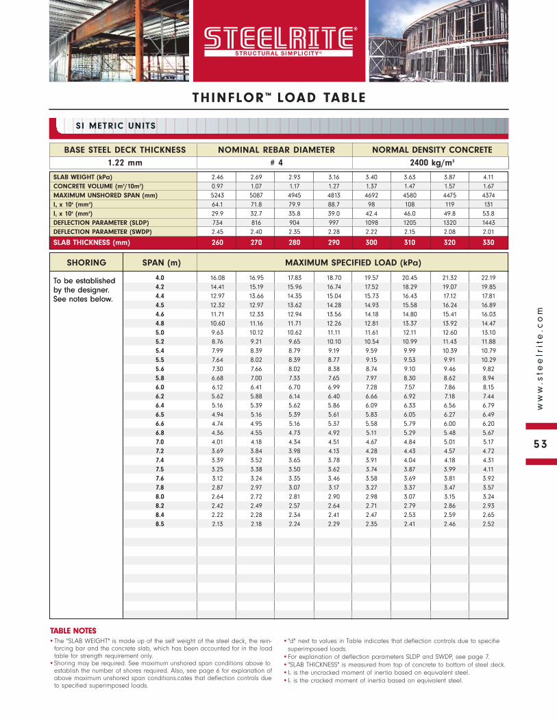
THINFLOR ™ LOAD TABLE
To be established by the designer. See notes below.
NORMAL DENSITY CONCRETE
2400 kg/m3
BASE STEEL DECK THICKNESS
1.22 mm
NOMINAL REBAR DIAMETER
# 4
SI METRIC UNITS
•The "SLAB WEIGHT" is made up of the self weight of the steel deck, the rein-forcing bar and the concrete slab, which has been accounted for in the load table for strength requirement only.
•Shoring may be required. See maximum unshored span conditions above to establish the number of shores required. Also, see page 6 for explanation of above maximum unshored span conditions.cates that deflection controls due to specified superimposed loads.
•"d" next to values in Table indicates that deflection controls due to specifiesuperimposed loads.
•For explanation of deflection parameters SLDP and SWDP, see page 7.•"SLAB THICKNESS" is measured from top of concrete to bottom of steel deck.•Iu is the uncracked moment of inertia based on equivalent steel.•Ic is the cracked moment of inertia based on equivalent steel.
TABLE NOTES
SHORING SPAN (m) MAXIMUM SPECIFIED LOAD (kPa)
TH INFLOR ™ LOAD TABLE
To be established by the designer. See notes below.
NORMAL DENSITY CONCRETE
2400 kg/m3
BASE STEEL DECK THICKNESS
1.22 mm
NOMINAL REBAR DIAMETER
# 4
SI METRIC UNITS
TABLE NOTES
SHORING SPAN (m) MAXIMUM SPECIFIED LOAD (kPa)
SLAB WEIGHT (kPa) 2.46 2.69 2.93 3.16 3.40 3.63 3.87 4.11CONCRETE VOLUME (m3/10m2) 0.97 1.07 1.17 1.27 1.37 1.47 1.57 1.67MAXIMUM UNSHORED SPAN (mm) 5243 5087 4945 4813 4692 4580 4475 4374Iu x 106 (mm4) 64.1 71.8 79.9 88.7 98 108 119 131Ic x 106 (mm4) 29.9 32.7 35.8 39.0 42.4 46.0 49.8 53.8DEFLECTION PARAMETER (SLDP) 734 816 904 997 1098 1205 1320 1443DEFLECTION PARAMETER (SWDP) 2.45 2.40 2.35 2.28 2.22 2.15 2.08 2.01
SLAB THICKNESS (mm) 260 270 280 290 300 310 320 330
4.0 16.08 16.95 17.83 18.70 19.57 20.45 21.32 22.194.2 14.41 15.19 15.96 16.74 17.52 18.29 19.07 19.854.4 12.97 13.66 14.35 15.04 15.73 16.43 17.12 17.814.5 12.32 12.97 13.62 14.28 14.93 15.58 16.24 16.894.6 11.71 12.33 12.94 13.56 14.18 14.80 15.41 16.034.8 10.60 11.16 11.71 12.26 12.81 13.37 13.92 14.475.0 9.63 10.12 10.62 11.11 11.61 12.11 12.60 13.105.2 8.76 9.21 9.65 10.10 10.54 10.99 11.43 11.885.4 7.99 8.39 8.79 9.19 9.59 9.99 10.39 10.795.5 7.64 8.02 8.39 8.77 9.15 9.53 9.91 10.295.6 7.30 7.66 8.02 8.38 8.74 9.10 9.46 9.825.8 6.68 7.00 7.33 7.65 7.97 8.30 8.62 8.946.0 6.12 6.41 6.70 6.99 7.28 7.57 7.86 8.156.2 5.62 5.88 6.14 6.40 6.66 6.92 7.18 7.446.4 5.16 5.39 5.62 5.86 6.09 6.33 6.56 6.796.5 4.94 5.16 5.39 5.61 5.83 6.05 6.27 6.496.6 4.74 4.95 5.16 5.37 5.58 5.79 6.00 6.206.8 4.36 4.55 4.73 4.92 5.11 5.29 5.48 5.677.0 4.01 4.18 4.34 4.51 4.67 4.84 5.01 5.177.2 3.69 3.84 3.98 4.13 4.28 4.43 4.57 4.727.4 3.39 3.52 3.65 3.78 3.91 4.04 4.18 4.317.5 3.25 3.38 3.50 3.62 3.74 3.87 3.99 4.117.6 3.12 3.24 3.35 3.46 3.58 3.69 3.81 3.927.8 2.87 2.97 3.07 3.17 3.27 3.37 3.47 3.578.0 2.64 2.72 2.81 2.90 2.98 3.07 3.15 3.248.2 2.42 2.49 2.57 2.64 2.71 2.79 2.86 2.938.4 2.22 2.28 2.34 2.41 2.47 2.53 2.59 2.658.5 2.13 2.18 2.24 2.29 2.35 2.41 2.46 2.52
53
ww
w.s
tee
lrit
e.c
om
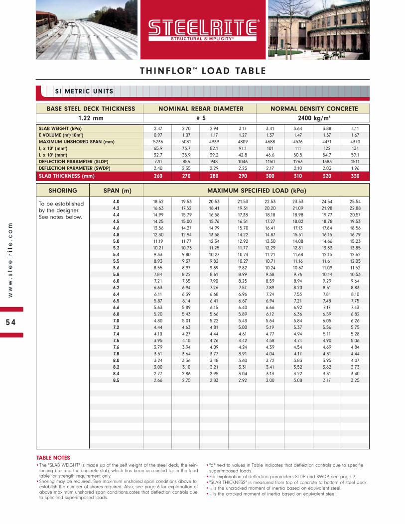
To be established by the designer. See notes below.
SHORING SPAN (m) MAXIMUM SPECIFIED LOAD (kPa)
NORMAL DENSITY CONCRETE
2400 kg/m3
BASE STEEL DECK THICKNESS
1.22 mm
NOMINAL REBAR DIAMETER
# 5
SI METRIC UNITS
•The "SLAB WEIGHT" is made up of the self weight of the steel deck, the rein-forcing bar and the concrete slab, which has been accounted for in the load table for strength requirement only.
•Shoring may be required. See maximum unshored span conditions above to establish the number of shores required. Also, see page 6 for explanation of above maximum unshored span conditions.cates that deflection controls due to specified superimposed loads.
•"d" next to values in Table indicates that deflection controls due to specifiesuperimposed loads.
•For explanation of deflection parameters SLDP and SWDP, see page 7.•"SLAB THICKNESS" is measured from top of concrete to bottom of steel deck.•Iu is the uncracked moment of inertia based on equivalent steel.•Ic is the cracked moment of inertia based on equivalent steel.
TABLE NOTES
SLAB WEIGHT (kPa) 2.47 2.70 2.94 3.17 3.41 3.64 3.88 4.11E VOLUME (m3/10m2) 0.97 1.07 1.17 1.27 1.37 1.47 1.57 1.67MAXIMUM UNSHORED SPAN (mm) 5236 5081 4939 4809 4688 4576 4471 4370Iu x 106 (mm4) 65.9 73.7 82.1 91.1 101 111 122 134Ic x 106 (mm4) 32.7 35.9 39.2 42.8 46.6 50.5 54.7 59.1DEFLECTION PARAMETER (SLDP) 770 856 948 1046 1150 1263 1383 1511DEFLECTION PARAMETER (SWDP) 2.40 2.35 2.29 2.23 2.17 2.10 2.03 1.96
SLAB THICKNESS (mm) 260 270 280 290 300 310 320 330
4.0 18.52 19.53 20.53 21.53 22.53 23.53 24.54 25.544.2 16.63 17.52 18.41 19.31 20.20 21.09 21.98 22.884.4 14.99 15.79 16.58 17.38 18.18 18.98 19.77 20.574.5 14.25 15.00 15.76 16.51 17.27 18.02 18.78 19.534.6 13.56 14.27 14.99 15.70 16.41 17.13 17.84 18.564.8 12.30 12.94 13.58 14.22 14.87 15.51 16.15 16.795.0 11.19 11.77 12.34 12.92 13.50 14.08 14.66 15.235.2 10.21 10.73 11.25 11.77 12.29 12.81 13.33 13.855.4 9.33 9.80 10.27 10.74 11.21 11.68 12.15 12.625.5 8.93 9.37 9.82 10.27 10.71 11.16 11.61 12.055.6 8.55 8.97 9.39 9.82 10.24 10.67 11.09 11.525.8 7.84 8.22 8.61 8.99 9.38 9.76 10.14 10.536.0 7.21 7.55 7.90 8.25 8.59 8.94 9.29 9.646.2 6.63 6.94 7.26 7.57 7.89 8.20 8.51 8.836.4 6.11 6.39 6.68 6.96 7.24 7.53 7.81 8.106.5 5.87 6.14 6.41 6.67 6.94 7.21 7.48 7.756.6 5.63 5.89 6.15 6.40 6.66 6.92 7.17 7.436.8 5.20 5.43 5.66 5.89 6.12 6.36 6.59 6.827.0 4.80 5.01 5.22 5.43 5.64 5.84 6.05 6.267.2 4.44 4.63 4.81 5.00 5.19 5.37 5.56 5.757.4 4.10 4.27 4.44 4.61 4.77 4.94 5.11 5.287.5 3.95 4.10 4.26 4.42 4.58 4.74 4.90 5.067.6 3.79 3.94 4.09 4.24 4.39 4.54 4.69 4.847.8 3.51 3.64 3.77 3.91 4.04 4.17 4.31 4.448.0 3.24 3.36 3.48 3.60 3.72 3.83 3.95 4.078.2 3.00 3.10 3.21 3.31 3.41 3.52 3.62 3.738.4 2.77 2.86 2.95 3.04 3.13 3.22 3.31 3.408.5 2.66 2.75 2.83 2.92 3.00 3.08 3.17 3.25
THINFLOR ™ LOAD TABLE
54
ww
w.s
tee
lrit
e.c
om
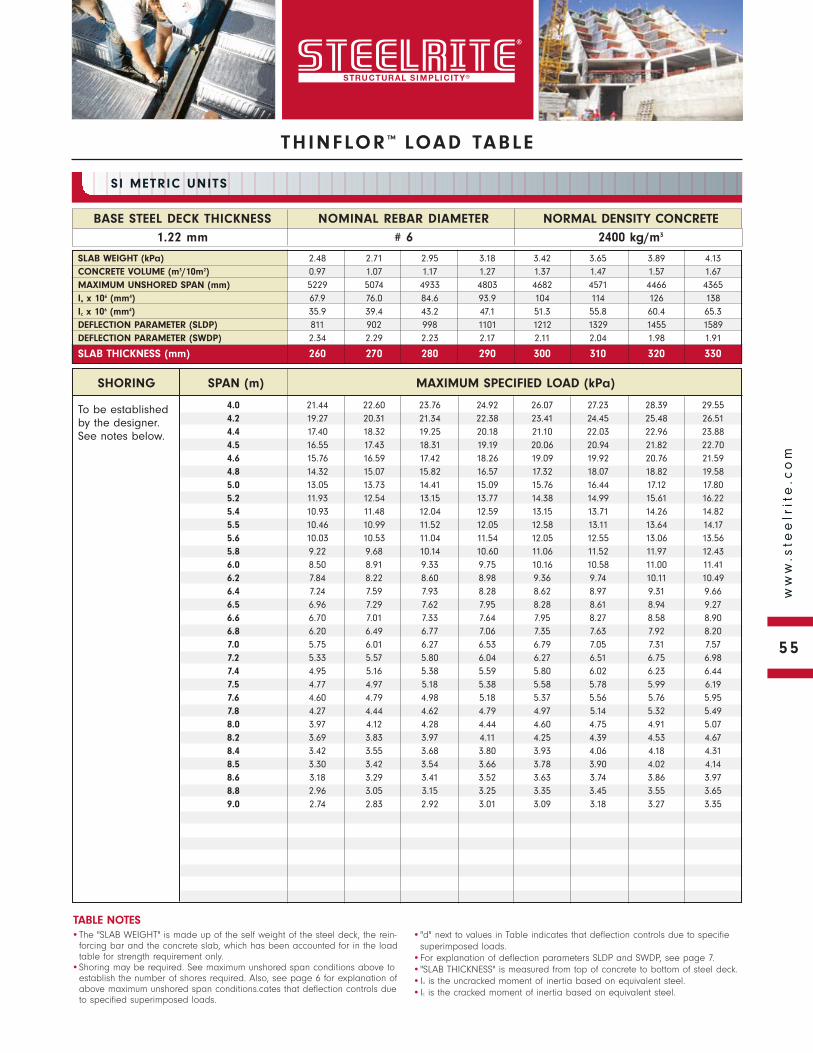
THINFLOR ™ LOAD TABLE
To be established by the designer. See notes below.
NORMAL DENSITY CONCRETE
2400 kg/m3
BASE STEEL DECK THICKNESS
1.22 mm
NOMINAL REBAR DIAMETER
# 6
SI METRIC UNITS
•The "SLAB WEIGHT" is made up of the self weight of the steel deck, the rein-forcing bar and the concrete slab, which has been accounted for in the load table for strength requirement only.
•Shoring may be required. See maximum unshored span conditions above to establish the number of shores required. Also, see page 6 for explanation of above maximum unshored span conditions.cates that deflection controls due to specified superimposed loads.
•"d" next to values in Table indicates that deflection controls due to specifiesuperimposed loads.
•For explanation of deflection parameters SLDP and SWDP, see page 7.•"SLAB THICKNESS" is measured from top of concrete to bottom of steel deck.•Iu is the uncracked moment of inertia based on equivalent steel.•Ic is the cracked moment of inertia based on equivalent steel.
TABLE NOTES
SLAB WEIGHT (kPa) 2.48 2.71 2.95 3.18 3.42 3.65 3.89 4.13CONCRETE VOLUME (m3/10m2) 0.97 1.07 1.17 1.27 1.37 1.47 1.57 1.67MAXIMUM UNSHORED SPAN (mm) 5229 5074 4933 4803 4682 4571 4466 4365Iu x 106 (mm4) 67.9 76.0 84.6 93.9 104 114 126 138Ic x 106 (mm4) 35.9 39.4 43.2 47.1 51.3 55.8 60.4 65.3DEFLECTION PARAMETER (SLDP) 811 902 998 1101 1212 1329 1455 1589DEFLECTION PARAMETER (SWDP) 2.34 2.29 2.23 2.17 2.11 2.04 1.98 1.91
SLAB THICKNESS (mm) 260 270 280 290 300 310 320 330
SHORING SPAN (m) MAXIMUM SPECIFIED LOAD (kPa)
4.0 21.44 22.60 23.76 24.92 26.07 27.23 28.39 29.554.2 19.27 20.31 21.34 22.38 23.41 24.45 25.48 26.514.4 17.40 18.32 19.25 20.18 21.10 22.03 22.96 23.884.5 16.55 17.43 18.31 19.19 20.06 20.94 21.82 22.704.6 15.76 16.59 17.42 18.26 19.09 19.92 20.76 21.594.8 14.32 15.07 15.82 16.57 17.32 18.07 18.82 19.585.0 13.05 13.73 14.41 15.09 15.76 16.44 17.12 17.805.2 11.93 12.54 13.15 13.77 14.38 14.99 15.61 16.225.4 10.93 11.48 12.04 12.59 13.15 13.71 14.26 14.825.5 10.46 10.99 11.52 12.05 12.58 13.11 13.64 14.175.6 10.03 10.53 11.04 11.54 12.05 12.55 13.06 13.565.8 9.22 9.68 10.14 10.60 11.06 11.52 11.97 12.436.0 8.50 8.91 9.33 9.75 10.16 10.58 11.00 11.416.2 7.84 8.22 8.60 8.98 9.36 9.74 10.11 10.496.4 7.24 7.59 7.93 8.28 8.62 8.97 9.31 9.666.5 6.96 7.29 7.62 7.95 8.28 8.61 8.94 9.276.6 6.70 7.01 7.33 7.64 7.95 8.27 8.58 8.906.8 6.20 6.49 6.77 7.06 7.35 7.63 7.92 8.207.0 5.75 6.01 6.27 6.53 6.79 7.05 7.31 7.577.2 5.33 5.57 5.80 6.04 6.27 6.51 6.75 6.987.4 4.95 5.16 5.38 5.59 5.80 6.02 6.23 6.447.5 4.77 4.97 5.18 5.38 5.58 5.78 5.99 6.197.6 4.60 4.79 4.98 5.18 5.37 5.56 5.76 5.957.8 4.27 4.44 4.62 4.79 4.97 5.14 5.32 5.498.0 3.97 4.12 4.28 4.44 4.60 4.75 4.91 5.078.2 3.69 3.83 3.97 4.11 4.25 4.39 4.53 4.678.4 3.42 3.55 3.68 3.80 3.93 4.06 4.18 4.318.5 3.30 3.42 3.54 3.66 3.78 3.90 4.02 4.148.6 3.18 3.29 3.41 3.52 3.63 3.74 3.86 3.978.8 2.96 3.05 3.15 3.25 3.35 3.45 3.55 3.659.0 2.74 2.83 2.92 3.01 3.09 3.18 3.27 3.35
55
ww
w.s
tee
lrit
e.c
om
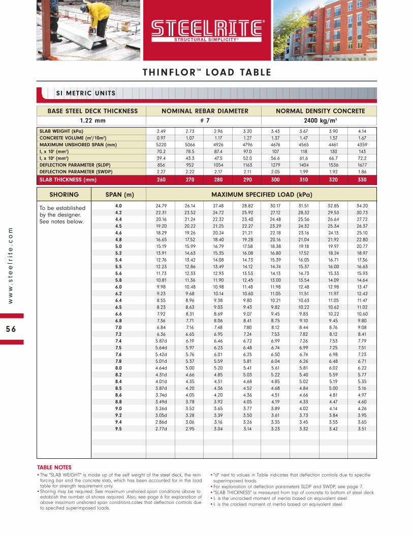
To be established by the designer. See notes below.
SHORING SPAN (m) MAXIMUM SPECIFIED LOAD (kPa)
NORMAL DENSITY CONCRETE
2400 kg/m3
BASE STEEL DECK THICKNESS
1.22 mm
NOMINAL REBAR DIAMETER
# 7
SI METRIC UNITS
•The "SLAB WEIGHT" is made up of the self weight of the steel deck, the rein-forcing bar and the concrete slab, which has been accounted for in the load table for strength requirement only.
•Shoring may be required. See maximum unshored span conditions above to establish the number of shores required. Also, see page 6 for explanation of above maximum unshored span conditions.cates that deflection controls due to specified superimposed loads.
•"d" next to values in Table indicates that deflection controls due to specifiesuperimposed loads.
•For explanation of deflection parameters SLDP and SWDP, see page 7.•"SLAB THICKNESS" is measured from top of concrete to bottom of steel deck.•Iu is the uncracked moment of inertia based on equivalent steel.•Ic is the cracked moment of inertia based on equivalent steel.
TABLE NOTES
SLAB WEIGHT (kPa) 2.49 2.73 2.96 3.20 3.43 3.67 3.90 4.14CONCRETE VOLUME (m3/10m2) 0.97 1.07 1.17 1.27 1.37 1.47 1.57 1.67MAXIMUM UNSHORED SPAN (mm) 5220 5066 4926 4796 4676 4565 4461 4359Iu x 106 (mm4) 70.2 78.5 87.4 97.0 107 118 130 143Ic x 106 (mm4) 39.4 43.3 47.5 52.0 56.6 61.6 66.7 72.2DEFLECTION PARAMETER (SLDP) 856 952 1054 1163 1279 1404 1536 1677DEFLECTION PARAMETER (SWDP) 2.27 2.22 2.17 2.11 2.05 1.99 1.92 1.86
SLAB THICKNESS (mm) 260 270 280 290 300 310 320 330
4.0 24.79 26.14 27.48 28.82 30.17 31.51 32.85 34.204.2 22.31 23.52 24.72 25.92 27.12 28.32 29.53 30.734.4 20.16 21.24 22.32 23.40 24.48 25.56 26.64 27.724.5 19.20 20.22 21.25 22.27 23.29 24.32 25.34 26.374.6 18.29 19.26 20.24 21.21 22.18 23.16 24.13 25.104.8 16.65 17.52 18.40 19.28 20.16 21.04 21.92 22.805.0 15.19 15.99 16.79 17.58 18.38 19.18 19.97 20.775.2 13.91 14.63 15.35 16.08 16.80 17.52 18.24 18.975.4 12.76 13.42 14.08 14.73 15.39 16.05 16.71 17.365.5 12.23 12.86 13.49 14.12 14.74 15.37 16.00 16.635.6 11.73 12.33 12.93 13.53 14.13 14.73 15.33 15.935.8 10.81 11.36 11.90 12.45 13.00 13.54 14.09 14.646.0 9.98 10.48 10.98 11.48 11.98 12.48 12.98 13.476.2 9.23 9.68 10.14 10.60 11.05 11.51 11.97 12.426.4 8.55 8.96 9.38 9.80 10.21 10.63 11.05 11.476.5 8.23 8.63 9.03 9.43 9.82 10.22 10.62 11.026.6 7.92 8.31 8.69 9.07 9.45 9.83 10.22 10.606.8 7.36 7.71 8.06 8.41 8.75 9.10 9.45 9.807.0 6.84 7.16 7.48 7.80 8.12 8.44 8.76 9.087.2 6.36 6.65 6.95 7.24 7.53 7.82 8.12 8.417.4 5.87d 6.19 6.46 6.72 6.99 7.26 7.53 7.797.5 5.64d 5.97 6.23 6.48 6.74 6.99 7.25 7.517.6 5.42d 5.76 6.01 6.25 6.50 6.74 6.98 7.237.8 5.01d 5.37 5.59 5.81 6.04 6.26 6.48 6.718.0 4.64d 5.00 5.20 5.41 5.61 5.81 6.02 6.228.2 4.31d 4.66 4.85 5.03 5.22 5.40 5.59 5.778.4 4.01d 4.35 4.51 4.68 4.85 5.02 5.19 5.358.5 3.87d 4.20 4.36 4.52 4.68 4.84 5.00 5.168.6 3.74d 4.05 4.20 4.36 4.51 4.66 4.81 4.978.8 3.49d 3.78 3.92 4.05 4.19 4.33 4.47 4.609.0 3.26d 3.52 3.65 3.77 3.89 4.02 4.14 4.269.2 3.05d 3.28 3.39 3.50 3.61 3.73 3.84 3.959.4 2.86d 3.06 3.16 3.26 3.35 3.45 3.55 3.659.5 2.77d 2.95 3.04 3.14 3.23 3.32 3.42 3.51
THINFLOR ™ LOAD TABLE
56
ww
w.s
tee
lrit
e.c
om

THINFLOR ™ LOAD TABLE
To be established by the designer. See notes below.
NORMAL DENSITY CONCRETE
2400 kg/m3
BASE STEEL DECK THICKNESS
1.22 mm
NOMINAL REBAR DIAMETER
# 8
SI METRIC UNITS
•The "SLAB WEIGHT" is made up of the self weight of the steel deck, the rein-forcing bar and the concrete slab, which has been accounted for in the load table for strength requirement only.
•Shoring may be required. See maximum unshored span conditions above to establish the number of shores required. Also, see page 6 for explanation of above maximum unshored span conditions.cates that deflection controls due to specified superimposed loads.
•"d" next to values in Table indicates that deflection controls due to specifiesuperimposed loads.
•For explanation of deflection parameters SLDP and SWDP, see page 7.•"SLAB THICKNESS" is measured from top of concrete to bottom of steel deck.•Iu is the uncracked moment of inertia based on equivalent steel.•Ic is the cracked moment of inertia based on equivalent steel.
TABLE NOTES
SLAB WEIGHT (kPa) 2.51 2.74 2.98 3.21 3.45 3.68 3.92 4.15CONCRETE VOLUME (m3/10m2) 0.97 1.07 1.17 1.27 1.37 1.47 1.57 1.67MAXIMUM UNSHORED SPAN (mm) 5210 5057 4917 4788 4669 4558 4455 4352Iu x 106 (mm4) 72.6 81.3 90.5 100.4 111 122 134 147Ic x 106 (mm4) 43.2 47.5 52.2 57.1 62.3 67.8 73.6 79.6DEFLECTION PARAMETER (SLDP) 904 1006 1114 1230 1353 1484 1624 1772DEFLECTION PARAMETER (SWDP) 2.21 2.16 2.11 2.05 1.99 1.93 1.87 1.80
SLAB THICKNESS (mm) 260 270 280 290 300 310 320 330
SHORING SPAN (m) MAXIMUM SPECIFIED LOAD (kPa)
4.5 22.16 23.35 24.54 25.74 26.93 28.12 29.32 30.514.6 21.12 22.26 23.39 24.53 25.66 26.79 27.93 29.064.8 19.25 20.27 21.30 22.33 23.35 24.38 25.41 26.445.0 17.59 18.52 19.45 20.39 21.32 22.25 23.19 24.125.2 16.12 16.97 17.82 18.67 19.52 20.37 21.22 22.075.4 14.81 15.59 16.36 17.14 17.91 18.69 19.46 20.235.5 14.21 14.95 15.69 16.43 17.17 17.91 18.65 19.395.6 13.64 14.35 15.06 15.76 16.47 17.18 17.89 18.605.8 12.59 13.24 13.88 14.53 15.18 15.83 16.48 17.136.0 11.62d 12.23 12.83 13.42 14.02 14.61 15.20 15.806.2 10.53d 11.33 11.87 12.42 12.96 13.51 14.05 14.606.4 9.58d 10.50 11.00 11.51 12.01 12.51 13.01 13.516.5 9.14d 10.12 10.60 11.08 11.56 12.04 12.52 13.006.6 8.73d 9.72d 10.21 10.67 11.13 11.60 12.06 12.526.8 7.98d 8.89d 9.49 9.92 10.34 10.76 11.19 11.617.0 7.32d 8.15d 8.83 9.22 9.61 10.00 10.39 10.787.2 6.73d 7.49d 8.23 8.58 8.94 9.30 9.66 10.027.4 6.20d 6.89d 7.64d 8.00 8.33 8.66 8.99 9.327.5 5.95d 6.62d 7.34d 7.72 8.04 8.36 8.67 8.997.6 5.72d 6.36d 7.05d 7.46 7.76 8.07 8.37 8.677.8 5.29d 5.89d 6.52d 6.96 7.24 7.52 7.80 8.088.0 4.90d 5.46d 6.05d 6.50 6.75 7.01 7.27 7.528.2 4.55d 5.07d 5.61d 6.07 6.30 6.54 6.78 7.018.4 4.24d 4.71d 5.22d 5.67 5.88 6.10 6.32 6.538.5 4.09d 4.55d 5.04d 5.48 5.69 5.89 6.10 6.318.6 3.95d 4.39d 4.87d 5.30 5.50 5.69 5.89 6.098.8 3.68d 4.10d 4.54d 4.95 5.13 5.31 5.50 5.689.0 3.44d 3.83d 4.25d 4.63 4.79 4.96 5.12 5.299.2 3.22d 3.59d 3.98d 4.32 4.48 4.63 4.78 4.939.4 3.02d 3.36d 3.73d 4.04 4.18 4.32 4.45 4.599.5 2.93d 3.26d 3.61d 3.91 4.04 4.17 4.30 4.439.6 2.84d 3.16d 3.50d 3.78 3.90 4.02 4.15 4.279.8 2.67d 2.97d 3.29d 3.53 3.64 3.75 3.86 3.9710.0 2.51d 2.79d 3.10d 3.29 3.39 3.49 3.59 3.69
57
ww
w.s
tee
lrit
e.c
om
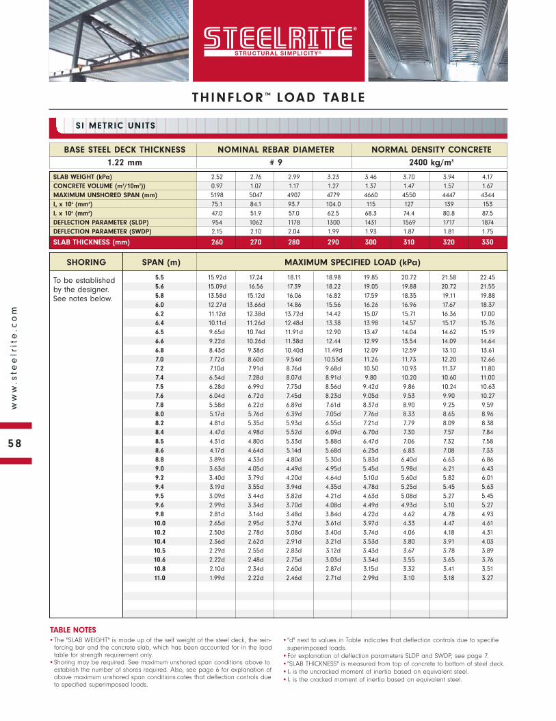
To be established by the designer. See notes below.
SHORING SPAN (m) MAXIMUM SPECIFIED LOAD (kPa)
NORMAL DENSITY CONCRETE
2400 kg/m3
BASE STEEL DECK THICKNESS
1.22 mm
NOMINAL REBAR DIAMETER
# 9
SI METRIC UNITS
•The "SLAB WEIGHT" is made up of the self weight of the steel deck, the rein-forcing bar and the concrete slab, which has been accounted for in the load table for strength requirement only.
•Shoring may be required. See maximum unshored span conditions above to establish the number of shores required. Also, see page 6 for explanation of above maximum unshored span conditions.cates that deflection controls due to specified superimposed loads.
•"d" next to values in Table indicates that deflection controls due to specifiesuperimposed loads.
•For explanation of deflection parameters SLDP and SWDP, see page 7.•"SLAB THICKNESS" is measured from top of concrete to bottom of steel deck.•Iu is the uncracked moment of inertia based on equivalent steel.•Ic is the cracked moment of inertia based on equivalent steel.
TABLE NOTES
SLAB WEIGHT (kPa) 2.52 2.76 2.99 3.23 3.46 3.70 3.94 4.17CONCRETE VOLUME (m3/10m2)) 0.97 1.07 1.17 1.27 1.37 1.47 1.57 1.67MAXIMUM UNSHORED SPAN (mm) 5198 5047 4907 4779 4660 4550 4447 4344Iu x 106 (mm4) 75.1 84.1 93.7 104.0 115 127 139 153Ic x 106 (mm4) 47.0 51.9 57.0 62.5 68.3 74.4 80.8 87.5DEFLECTION PARAMETER (SLDP) 954 1062 1178 1300 1431 1569 1717 1874DEFLECTION PARAMETER (SWDP) 2.15 2.10 2.04 1.99 1.93 1.87 1.81 1.75
SLAB THICKNESS (mm) 260 270 280 290 300 310 320 330
5.5 15.92d 17.24 18.11 18.98 19.85 20.72 21.58 22.455.6 15.09d 16.56 17.39 18.22 19.05 19.88 20.72 21.555.8 13.58d 15.12d 16.06 16.82 17.59 18.35 19.11 19.886.0 12.27d 13.66d 14.86 15.56 16.26 16.96 17.67 18.376.2 11.12d 12.38d 13.72d 14.42 15.07 15.71 16.36 17.006.4 10.11d 11.26d 12.48d 13.38 13.98 14.57 15.17 15.766.5 9.65d 10.74d 11.91d 12.90 13.47 14.04 14.62 15.196.6 9.22d 10.26d 11.38d 12.44 12.99 13.54 14.09 14.646.8 8.43d 9.38d 10.40d 11.49d 12.09 12.59 13.10 13.617.0 7.72d 8.60d 9.54d 10.53d 11.26 11.73 12.20 12.667.2 7.10d 7.91d 8.76d 9.68d 10.50 10.93 11.37 11.807.4 6.54d 7.28d 8.07d 8.91d 9.80 10.20 10.60 11.007.5 6.28d 6.99d 7.75d 8.56d 9.42d 9.86 10.24 10.637.6 6.04d 6.72d 7.45d 8.23d 9.05d 9.53 9.90 10.277.8 5.58d 6.22d 6.89d 7.61d 8.37d 8.90 9.25 9.598.0 5.17d 5.76d 6.39d 7.05d 7.76d 8.33 8.65 8.968.2 4.81d 5.35d 5.93d 6.55d 7.21d 7.79 8.09 8.388.4 4.47d 4.98d 5.52d 6.09d 6.70d 7.30 7.57 7.848.5 4.31d 4.80d 5.33d 5.88d 6.47d 7.06 7.32 7.588.6 4.17d 4.64d 5.14d 5.68d 6.25d 6.83 7.08 7.338.8 3.89d 4.33d 4.80d 5.30d 5.83d 6.40d 6.63 6.869.0 3.63d 4.05d 4.49d 4.95d 5.45d 5.98d 6.21 6.439.2 3.40d 3.79d 4.20d 4.64d 5.10d 5.60d 5.82 6.019.4 3.19d 3.55d 3.94d 4.35d 4.78d 5.25d 5.45 5.639.5 3.09d 3.44d 3.82d 4.21d 4.63d 5.08d 5.27 5.459.6 2.99d 3.34d 3.70d 4.08d 4.49d 4.93d 5.10 5.279.8 2.81d 3.14d 3.48d 3.84d 4.22d 4.62 4.78 4.9310.0 2.65d 2.95d 3.27d 3.61d 3.97d 4.33 4.47 4.6110.2 2.50d 2.78d 3.08d 3.40d 3.74d 4.06 4.18 4.3110.4 2.36d 2.62d 2.91d 3.21d 3.53d 3.80 3.91 4.0310.5 2.29d 2.55d 2.83d 3.12d 3.43d 3.67 3.78 3.8910.6 2.22d 2.48d 2.75d 3.03d 3.34d 3.55 3.65 3.7610.8 2.10d 2.34d 2.60d 2.87d 3.15d 3.32 3.41 3.5111.0 1.99d 2.22d 2.46d 2.71d 2.99d 3.10 3.18 3.27
THINFLOR ™ LOAD TABLE
58
ww
w.s
tee
lrit
e.c
om
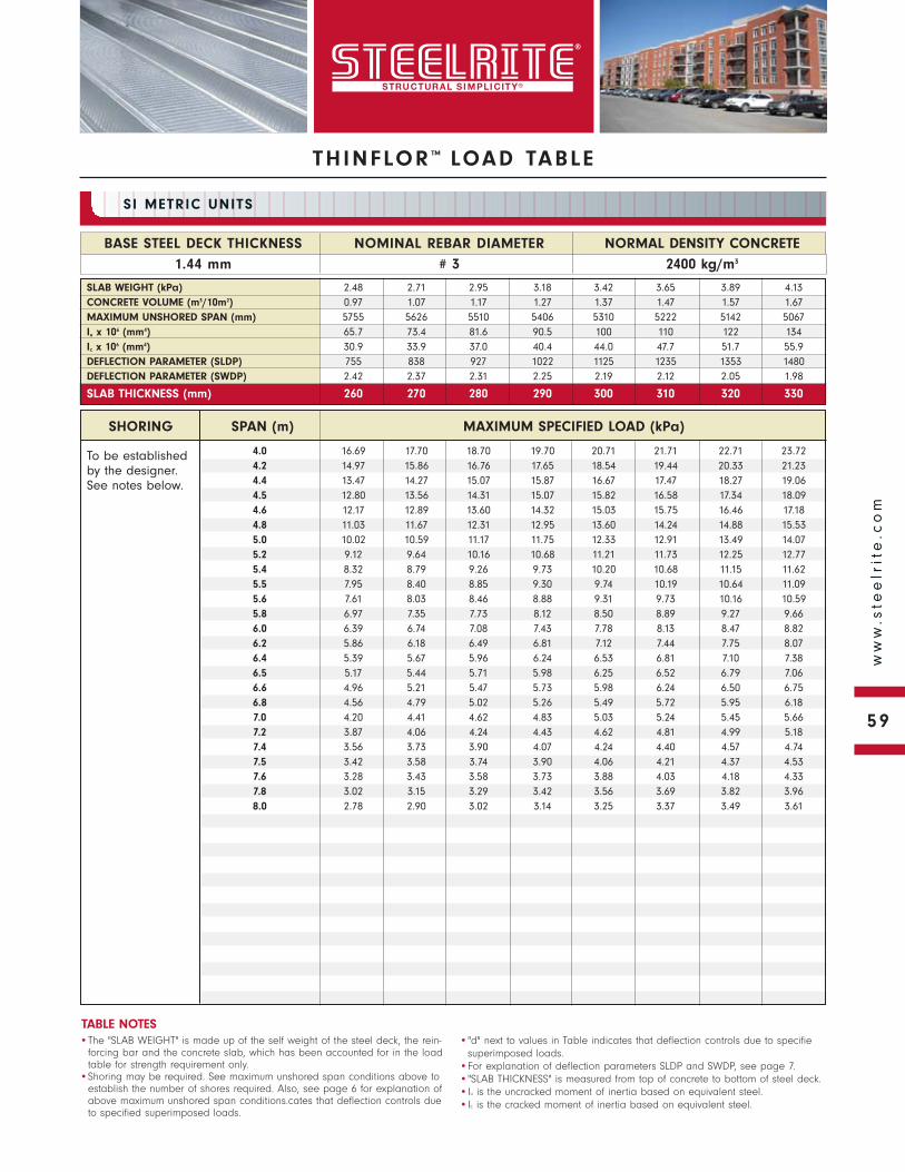
THINFLOR ™ LOAD TABLE
To be established by the designer. See notes below.
NORMAL DENSITY CONCRETE
2400 kg/m3
BASE STEEL DECK THICKNESS
1.44 mm
NOMINAL REBAR DIAMETER
# 3
SI METRIC UNITS
•The "SLAB WEIGHT" is made up of the self weight of the steel deck, the rein-forcing bar and the concrete slab, which has been accounted for in the load table for strength requirement only.
•Shoring may be required. See maximum unshored span conditions above to establish the number of shores required. Also, see page 6 for explanation of above maximum unshored span conditions.cates that deflection controls due to specified superimposed loads.
•"d" next to values in Table indicates that deflection controls due to specifiesuperimposed loads.
•For explanation of deflection parameters SLDP and SWDP, see page 7.•"SLAB THICKNESS" is measured from top of concrete to bottom of steel deck.•Iu is the uncracked moment of inertia based on equivalent steel.•Ic is the cracked moment of inertia based on equivalent steel.
TABLE NOTES
SLAB WEIGHT (kPa) 2.48 2.71 2.95 3.18 3.42 3.65 3.89 4.13CONCRETE VOLUME (m3/10m2) 0.97 1.07 1.17 1.27 1.37 1.47 1.57 1.67MAXIMUM UNSHORED SPAN (mm) 5755 5626 5510 5406 5310 5222 5142 5067Iu x 106 (mm4) 65.7 73.4 81.6 90.5 100 110 122 134Ic x 106 (mm4) 30.9 33.9 37.0 40.4 44.0 47.7 51.7 55.9DEFLECTION PARAMETER (SLDP) 755 838 927 1022 1125 1235 1353 1480DEFLECTION PARAMETER (SWDP) 2.42 2.37 2.31 2.25 2.19 2.12 2.05 1.98
SLAB THICKNESS (mm) 260 270 280 290 300 310 320 330
SHORING SPAN (m) MAXIMUM SPECIFIED LOAD (kPa)
4.0 16.69 17.70 18.70 19.70 20.71 21.71 22.71 23.724.2 14.97 15.86 16.76 17.65 18.54 19.44 20.33 21.234.4 13.47 14.27 15.07 15.87 16.67 17.47 18.27 19.064.5 12.80 13.56 14.31 15.07 15.82 16.58 17.34 18.094.6 12.17 12.89 13.60 14.32 15.03 15.75 16.46 17.184.8 11.03 11.67 12.31 12.95 13.60 14.24 14.88 15.535.0 10.02 10.59 11.17 11.75 12.33 12.91 13.49 14.075.2 9.12 9.64 10.16 10.68 11.21 11.73 12.25 12.775.4 8.32 8.79 9.26 9.73 10.20 10.68 11.15 11.625.5 7.95 8.40 8.85 9.30 9.74 10.19 10.64 11.095.6 7.61 8.03 8.46 8.88 9.31 9.73 10.16 10.595.8 6.97 7.35 7.73 8.12 8.50 8.89 9.27 9.666.0 6.39 6.74 7.08 7.43 7.78 8.13 8.47 8.826.2 5.86 6.18 6.49 6.81 7.12 7.44 7.75 8.076.4 5.39 5.67 5.96 6.24 6.53 6.81 7.10 7.386.5 5.17 5.44 5.71 5.98 6.25 6.52 6.79 7.066.6 4.96 5.21 5.47 5.73 5.98 6.24 6.50 6.756.8 4.56 4.79 5.02 5.26 5.49 5.72 5.95 6.187.0 4.20 4.41 4.62 4.83 5.03 5.24 5.45 5.667.2 3.87 4.06 4.24 4.43 4.62 4.81 4.99 5.187.4 3.56 3.73 3.90 4.07 4.24 4.40 4.57 4.747.5 3.42 3.58 3.74 3.90 4.06 4.21 4.37 4.537.6 3.28 3.43 3.58 3.73 3.88 4.03 4.18 4.337.8 3.02 3.15 3.29 3.42 3.56 3.69 3.82 3.968.0 2.78 2.90 3.02 3.14 3.25 3.37 3.49 3.61
59
ww
w.s
tee
lrit
e.c
om
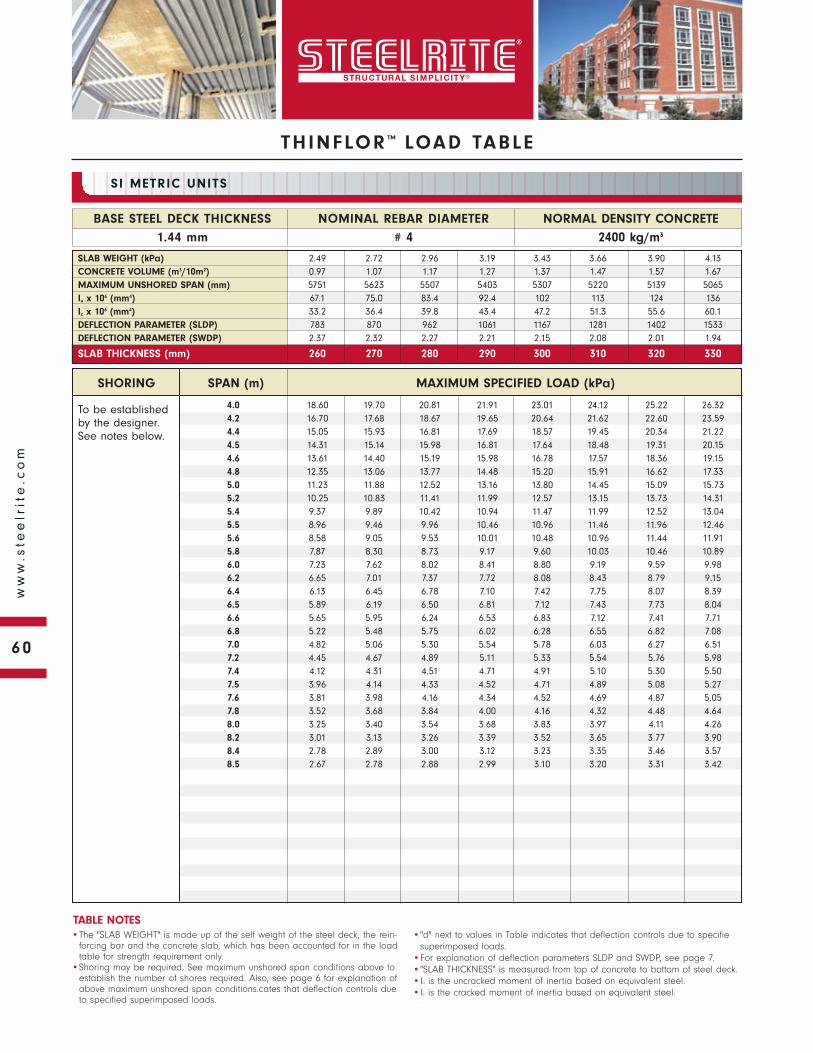
To be established by the designer. See notes below.
SHORING SPAN (m) MAXIMUM SPECIFIED LOAD (kPa)
NORMAL DENSITY CONCRETE
2400 kg/m3
BASE STEEL DECK THICKNESS
1.44 mm
NOMINAL REBAR DIAMETER
# 4
SI METRIC UNITS
•The "SLAB WEIGHT" is made up of the self weight of the steel deck, the rein-forcing bar and the concrete slab, which has been accounted for in the load table for strength requirement only.
•Shoring may be required. See maximum unshored span conditions above to establish the number of shores required. Also, see page 6 for explanation of above maximum unshored span conditions.cates that deflection controls due to specified superimposed loads.
•"d" next to values in Table indicates that deflection controls due to specifiesuperimposed loads.
•For explanation of deflection parameters SLDP and SWDP, see page 7.•"SLAB THICKNESS" is measured from top of concrete to bottom of steel deck.•Iu is the uncracked moment of inertia based on equivalent steel.•Ic is the cracked moment of inertia based on equivalent steel.
TABLE NOTES
SLAB WEIGHT (kPa) 2.49 2.72 2.96 3.19 3.43 3.66 3.90 4.13CONCRETE VOLUME (m3/10m2) 0.97 1.07 1.17 1.27 1.37 1.47 1.57 1.67MAXIMUM UNSHORED SPAN (mm) 5751 5623 5507 5403 5307 5220 5139 5065Iu x 106 (mm4) 67.1 75.0 83.4 92.4 102 113 124 136Ic x 106 (mm4) 33.2 36.4 39.8 43.4 47.2 51.3 55.6 60.1DEFLECTION PARAMETER (SLDP) 783 870 962 1061 1167 1281 1402 1533DEFLECTION PARAMETER (SWDP) 2.37 2.32 2.27 2.21 2.15 2.08 2.01 1.94
SLAB THICKNESS (mm) 260 270 280 290 300 310 320 330
4.0 18.60 19.70 20.81 21.91 23.01 24.12 25.22 26.324.2 16.70 17.68 18.67 19.65 20.64 21.62 22.60 23.594.4 15.05 15.93 16.81 17.69 18.57 19.45 20.34 21.224.5 14.31 15.14 15.98 16.81 17.64 18.48 19.31 20.154.6 13.61 14.40 15.19 15.98 16.78 17.57 18.36 19.154.8 12.35 13.06 13.77 14.48 15.20 15.91 16.62 17.335.0 11.23 11.88 12.52 13.16 13.80 14.45 15.09 15.735.2 10.25 10.83 11.41 11.99 12.57 13.15 13.73 14.315.4 9.37 9.89 10.42 10.94 11.47 11.99 12.52 13.045.5 8.96 9.46 9.96 10.46 10.96 11.46 11.96 12.465.6 8.58 9.05 9.53 10.01 10.48 10.96 11.44 11.915.8 7.87 8.30 8.73 9.17 9.60 10.03 10.46 10.896.0 7.23 7.62 8.02 8.41 8.80 9.19 9.59 9.986.2 6.65 7.01 7.37 7.72 8.08 8.43 8.79 9.156.4 6.13 6.45 6.78 7.10 7.42 7.75 8.07 8.396.5 5.89 6.19 6.50 6.81 7.12 7.43 7.73 8.046.6 5.65 5.95 6.24 6.53 6.83 7.12 7.41 7.716.8 5.22 5.48 5.75 6.02 6.28 6.55 6.82 7.087.0 4.82 5.06 5.30 5.54 5.78 6.03 6.27 6.517.2 4.45 4.67 4.89 5.11 5.33 5.54 5.76 5.987.4 4.12 4.31 4.51 4.71 4.91 5.10 5.30 5.507.5 3.96 4.14 4.33 4.52 4.71 4.89 5.08 5.277.6 3.81 3.98 4.16 4.34 4.52 4.69 4.87 5.057.8 3.52 3.68 3.84 4.00 4.16 4.32 4.48 4.648.0 3.25 3.40 3.54 3.68 3.83 3.97 4.11 4.268.2 3.01 3.13 3.26 3.39 3.52 3.65 3.77 3.908.4 2.78 2.89 3.00 3.12 3.23 3.35 3.46 3.578.5 2.67 2.78 2.88 2.99 3.10 3.20 3.31 3.42
THINFLOR ™ LOAD TABLE
60
ww
w.s
tee
lrit
e.c
om
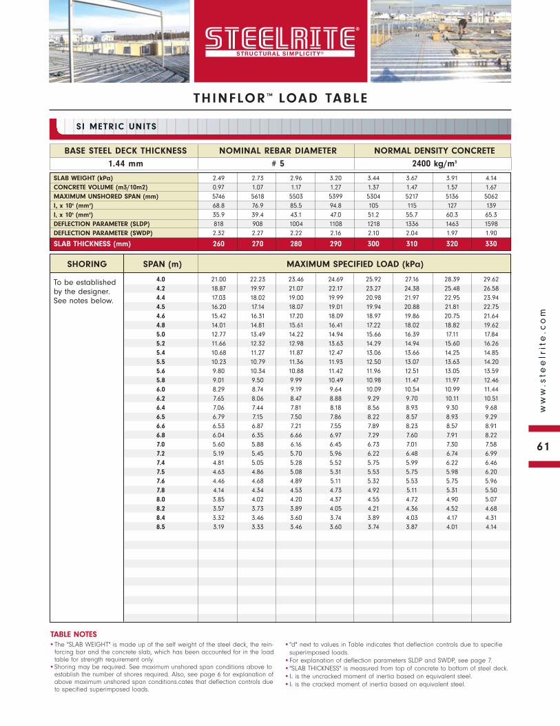
THINFLOR ™ LOAD TABLE
To be established by the designer. See notes below.
NORMAL DENSITY CONCRETE
2400 kg/m3
BASE STEEL DECK THICKNESS
1.44 mm
NOMINAL REBAR DIAMETER
# 5
SI METRIC UNITS
•The "SLAB WEIGHT" is made up of the self weight of the steel deck, the rein-forcing bar and the concrete slab, which has been accounted for in the load table for strength requirement only.
•Shoring may be required. See maximum unshored span conditions above to establish the number of shores required. Also, see page 6 for explanation of above maximum unshored span conditions.cates that deflection controls due to specified superimposed loads.
•"d" next to values in Table indicates that deflection controls due to specifiesuperimposed loads.
•For explanation of deflection parameters SLDP and SWDP, see page 7.•"SLAB THICKNESS" is measured from top of concrete to bottom of steel deck.•Iu is the uncracked moment of inertia based on equivalent steel.•Ic is the cracked moment of inertia based on equivalent steel.
TABLE NOTES
SLAB WEIGHT (kPa) 2.49 2.73 2.96 3.20 3.44 3.67 3.91 4.14CONCRETE VOLUME (m3/10m2) 0.97 1.07 1.17 1.27 1.37 1.47 1.57 1.67MAXIMUM UNSHORED SPAN (mm) 5746 5618 5503 5399 5304 5217 5136 5062Iu x 106 (mm4) 68.8 76.9 85.5 94.8 105 115 127 139Ic x 106 (mm4) 35.9 39.4 43.1 47.0 51.2 55.7 60.3 65.3DEFLECTION PARAMETER (SLDP) 818 908 1004 1108 1218 1336 1463 1598DEFLECTION PARAMETER (SWDP) 2.32 2.27 2.22 2.16 2.10 2.04 1.97 1.90
SLAB THICKNESS (mm) 260 270 280 290 300 310 320 330
SHORING SPAN (m) MAXIMUM SPECIFIED LOAD (kPa)
4.0 21.00 22.23 23.46 24.69 25.92 27.16 28.39 29.624.2 18.87 19.97 21.07 22.17 23.27 24.38 25.48 26.584.4 17.03 18.02 19.00 19.99 20.98 21.97 22.95 23.944.5 16.20 17.14 18.07 19.01 19.94 20.88 21.81 22.754.6 15.42 16.31 17.20 18.09 18.97 19.86 20.75 21.644.8 14.01 14.81 15.61 16.41 17.22 18.02 18.82 19.625.0 12.77 13.49 14.22 14.94 15.66 16.39 17.11 17.845.2 11.66 12.32 12.98 13.63 14.29 14.94 15.60 16.265.4 10.68 11.27 11.87 12.47 13.06 13.66 14.25 14.855.5 10.23 10.79 11.36 11.93 12.50 13.07 13.63 14.205.6 9.80 10.34 10.88 11.42 11.96 12.51 13.05 13.595.8 9.01 9.50 9.99 10.49 10.98 11.47 11.97 12.466.0 8.29 8.74 9.19 9.64 10.09 10.54 10.99 11.446.2 7.65 8.06 8.47 8.88 9.29 9.70 10.11 10.516.4 7.06 7.44 7.81 8.18 8.56 8.93 9.30 9.686.5 6.79 7.15 7.50 7.86 8.22 8.57 8.93 9.296.6 6.53 6.87 7.21 7.55 7.89 8.23 8.57 8.916.8 6.04 6.35 6.66 6.97 7.29 7.60 7.91 8.227.0 5.60 5.88 6.16 6.45 6.73 7.01 7.30 7.587.2 5.19 5.45 5.70 5.96 6.22 6.48 6.74 6.997.4 4.81 5.05 5.28 5.52 5.75 5.99 6.22 6.467.5 4.63 4.86 5.08 5.31 5.53 5.75 5.98 6.207.6 4.46 4.68 4.89 5.11 5.32 5.53 5.75 5.967.8 4.14 4.34 4.53 4.73 4.92 5.11 5.31 5.508.0 3.85 4.02 4.20 4.37 4.55 4.72 4.90 5.078.2 3.57 3.73 3.89 4.05 4.21 4.36 4.52 4.688.4 3.32 3.46 3.60 3.74 3.89 4.03 4.17 4.318.5 3.19 3.33 3.46 3.60 3.74 3.87 4.01 4.14
61
ww
w.s
tee
lrit
e.c
om
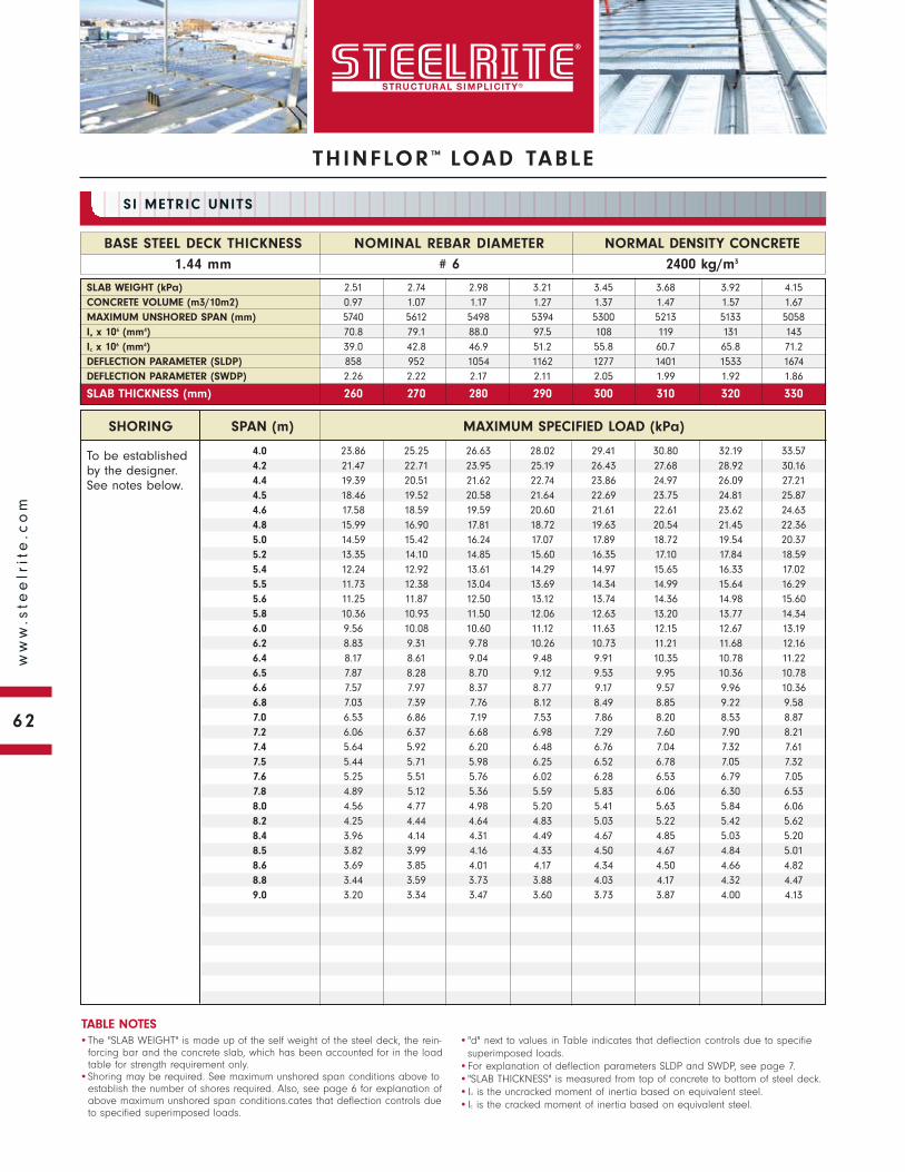
To be established by the designer. See notes below.
SHORING SPAN (m) MAXIMUM SPECIFIED LOAD (kPa)
NORMAL DENSITY CONCRETE
2400 kg/m3
BASE STEEL DECK THICKNESS
1.44 mm
NOMINAL REBAR DIAMETER
# 6
SI METRIC UNITS
•The "SLAB WEIGHT" is made up of the self weight of the steel deck, the rein-forcing bar and the concrete slab, which has been accounted for in the load table for strength requirement only.
•Shoring may be required. See maximum unshored span conditions above to establish the number of shores required. Also, see page 6 for explanation of above maximum unshored span conditions.cates that deflection controls due to specified superimposed loads.
•"d" next to values in Table indicates that deflection controls due to specifiesuperimposed loads.
•For explanation of deflection parameters SLDP and SWDP, see page 7.•"SLAB THICKNESS" is measured from top of concrete to bottom of steel deck.•Iu is the uncracked moment of inertia based on equivalent steel.•Ic is the cracked moment of inertia based on equivalent steel.
TABLE NOTES
SLAB WEIGHT (kPa) 2.51 2.74 2.98 3.21 3.45 3.68 3.92 4.15CONCRETE VOLUME (m3/10m2) 0.97 1.07 1.17 1.27 1.37 1.47 1.57 1.67MAXIMUM UNSHORED SPAN (mm) 5740 5612 5498 5394 5300 5213 5133 5058Iu x 106 (mm4) 70.8 79.1 88.0 97.5 108 119 131 143Ic x 106 (mm4) 39.0 42.8 46.9 51.2 55.8 60.7 65.8 71.2DEFLECTION PARAMETER (SLDP) 858 952 1054 1162 1277 1401 1533 1674DEFLECTION PARAMETER (SWDP) 2.26 2.22 2.17 2.11 2.05 1.99 1.92 1.86
SLAB THICKNESS (mm) 260 270 280 290 300 310 320 330
4.0 23.86 25.25 26.63 28.02 29.41 30.80 32.19 33.574.2 21.47 22.71 23.95 25.19 26.43 27.68 28.92 30.164.4 19.39 20.51 21.62 22.74 23.86 24.97 26.09 27.214.5 18.46 19.52 20.58 21.64 22.69 23.75 24.81 25.874.6 17.58 18.59 19.59 20.60 21.61 22.61 23.62 24.634.8 15.99 16.90 17.81 18.72 19.63 20.54 21.45 22.365.0 14.59 15.42 16.24 17.07 17.89 18.72 19.54 20.375.2 13.35 14.10 14.85 15.60 16.35 17.10 17.84 18.595.4 12.24 12.92 13.61 14.29 14.97 15.65 16.33 17.025.5 11.73 12.38 13.04 13.69 14.34 14.99 15.64 16.295.6 11.25 11.87 12.50 13.12 13.74 14.36 14.98 15.605.8 10.36 10.93 11.50 12.06 12.63 13.20 13.77 14.346.0 9.56 10.08 10.60 11.12 11.63 12.15 12.67 13.196.2 8.83 9.31 9.78 10.26 10.73 11.21 11.68 12.166.4 8.17 8.61 9.04 9.48 9.91 10.35 10.78 11.226.5 7.87 8.28 8.70 9.12 9.53 9.95 10.36 10.786.6 7.57 7.97 8.37 8.77 9.17 9.57 9.96 10.366.8 7.03 7.39 7.76 8.12 8.49 8.85 9.22 9.587.0 6.53 6.86 7.19 7.53 7.86 8.20 8.53 8.877.2 6.06 6.37 6.68 6.98 7.29 7.60 7.90 8.217.4 5.64 5.92 6.20 6.48 6.76 7.04 7.32 7.617.5 5.44 5.71 5.98 6.25 6.52 6.78 7.05 7.327.6 5.25 5.51 5.76 6.02 6.28 6.53 6.79 7.057.8 4.89 5.12 5.36 5.59 5.83 6.06 6.30 6.538.0 4.56 4.77 4.98 5.20 5.41 5.63 5.84 6.068.2 4.25 4.44 4.64 4.83 5.03 5.22 5.42 5.628.4 3.96 4.14 4.31 4.49 4.67 4.85 5.03 5.208.5 3.82 3.99 4.16 4.33 4.50 4.67 4.84 5.018.6 3.69 3.85 4.01 4.17 4.34 4.50 4.66 4.828.8 3.44 3.59 3.73 3.88 4.03 4.17 4.32 4.479.0 3.20 3.34 3.47 3.60 3.73 3.87 4.00 4.13
THINFLOR ™ LOAD TABLE
62
ww
w.s
tee
lrit
e.c
om
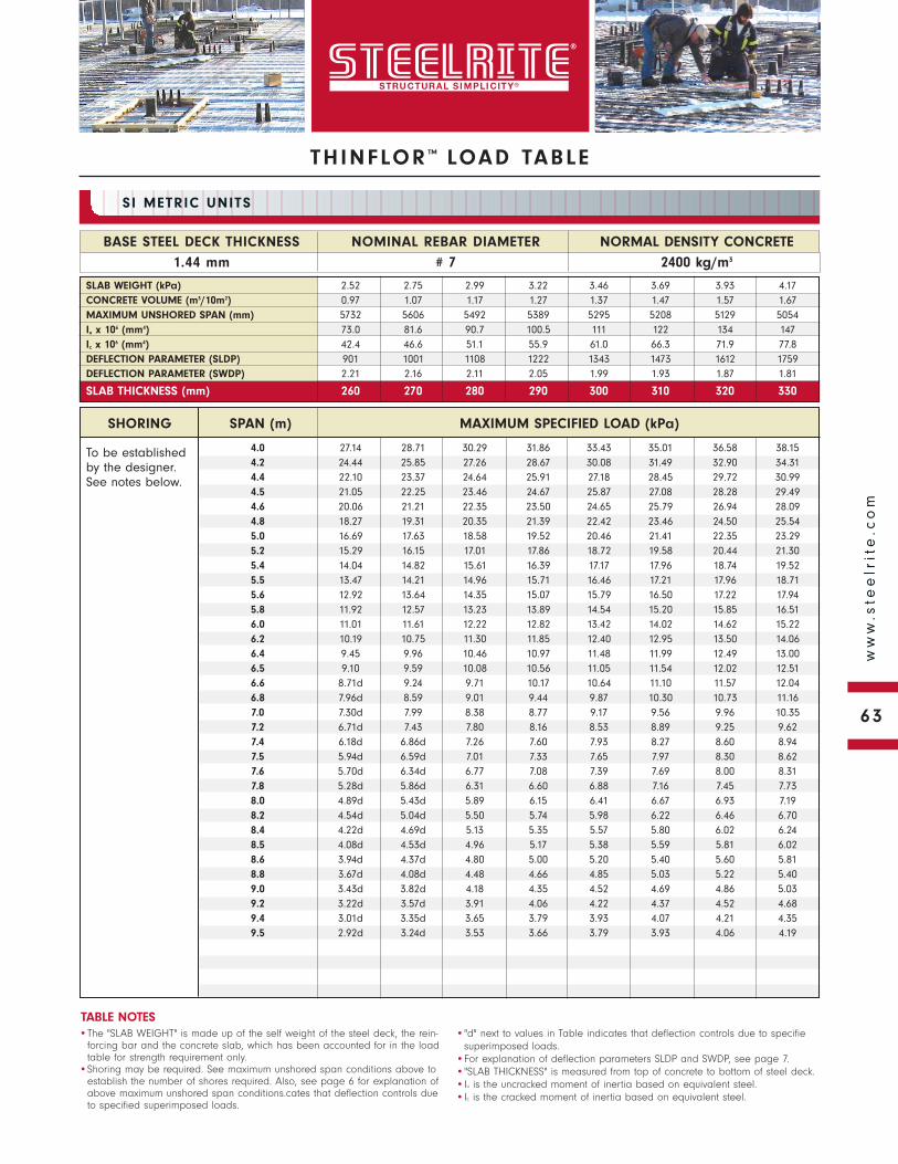
THINFLOR ™ LOAD TABLE
To be established by the designer. See notes below.
NORMAL DENSITY CONCRETE
2400 kg/m3
BASE STEEL DECK THICKNESS
1.44 mm
NOMINAL REBAR DIAMETER
# 7
SI METRIC UNITS
•The "SLAB WEIGHT" is made up of the self weight of the steel deck, the rein-forcing bar and the concrete slab, which has been accounted for in the load table for strength requirement only.
•Shoring may be required. See maximum unshored span conditions above to establish the number of shores required. Also, see page 6 for explanation of above maximum unshored span conditions.cates that deflection controls due to specified superimposed loads.
•"d" next to values in Table indicates that deflection controls due to specifiesuperimposed loads.
•For explanation of deflection parameters SLDP and SWDP, see page 7.•"SLAB THICKNESS" is measured from top of concrete to bottom of steel deck.•Iu is the uncracked moment of inertia based on equivalent steel.•Ic is the cracked moment of inertia based on equivalent steel.
TABLE NOTES
SLAB WEIGHT (kPa) 2.52 2.75 2.99 3.22 3.46 3.69 3.93 4.17CONCRETE VOLUME (m3/10m2) 0.97 1.07 1.17 1.27 1.37 1.47 1.57 1.67MAXIMUM UNSHORED SPAN (mm) 5732 5606 5492 5389 5295 5208 5129 5054Iu x 106 (mm4) 73.0 81.6 90.7 100.5 111 122 134 147Ic x 106 (mm4) 42.4 46.6 51.1 55.9 61.0 66.3 71.9 77.8DEFLECTION PARAMETER (SLDP) 901 1001 1108 1222 1343 1473 1612 1759DEFLECTION PARAMETER (SWDP) 2.21 2.16 2.11 2.05 1.99 1.93 1.87 1.81
SLAB THICKNESS (mm) 260 270 280 290 300 310 320 330
SHORING SPAN (m) MAXIMUM SPECIFIED LOAD (kPa)
4.0 27.14 28.71 30.29 31.86 33.43 35.01 36.58 38.154.2 24.44 25.85 27.26 28.67 30.08 31.49 32.90 34.314.4 22.10 23.37 24.64 25.91 27.18 28.45 29.72 30.994.5 21.05 22.25 23.46 24.67 25.87 27.08 28.28 29.494.6 20.06 21.21 22.35 23.50 24.65 25.79 26.94 28.094.8 18.27 19.31 20.35 21.39 22.42 23.46 24.50 25.545.0 16.69 17.63 18.58 19.52 20.46 21.41 22.35 23.295.2 15.29 16.15 17.01 17.86 18.72 19.58 20.44 21.305.4 14.04 14.82 15.61 16.39 17.17 17.96 18.74 19.525.5 13.47 14.21 14.96 15.71 16.46 17.21 17.96 18.715.6 12.92 13.64 14.35 15.07 15.79 16.50 17.22 17.945.8 11.92 12.57 13.23 13.89 14.54 15.20 15.85 16.516.0 11.01 11.61 12.22 12.82 13.42 14.02 14.62 15.226.2 10.19 10.75 11.30 11.85 12.40 12.95 13.50 14.066.4 9.45 9.96 10.46 10.97 11.48 11.99 12.49 13.006.5 9.10 9.59 10.08 10.56 11.05 11.54 12.02 12.516.6 8.71d 9.24 9.71 10.17 10.64 11.10 11.57 12.046.8 7.96d 8.59 9.01 9.44 9.87 10.30 10.73 11.167.0 7.30d 7.99 8.38 8.77 9.17 9.56 9.96 10.357.2 6.71d 7.43 7.80 8.16 8.53 8.89 9.25 9.627.4 6.18d 6.86d 7.26 7.60 7.93 8.27 8.60 8.947.5 5.94d 6.59d 7.01 7.33 7.65 7.97 8.30 8.627.6 5.70d 6.34d 6.77 7.08 7.39 7.69 8.00 8.317.8 5.28d 5.86d 6.31 6.60 6.88 7.16 7.45 7.738.0 4.89d 5.43d 5.89 6.15 6.41 6.67 6.93 7.198.2 4.54d 5.04d 5.50 5.74 5.98 6.22 6.46 6.708.4 4.22d 4.69d 5.13 5.35 5.57 5.80 6.02 6.248.5 4.08d 4.53d 4.96 5.17 5.38 5.59 5.81 6.028.6 3.94d 4.37d 4.80 5.00 5.20 5.40 5.60 5.818.8 3.67d 4.08d 4.48 4.66 4.85 5.03 5.22 5.409.0 3.43d 3.82d 4.18 4.35 4.52 4.69 4.86 5.039.2 3.22d 3.57d 3.91 4.06 4.22 4.37 4.52 4.689.4 3.01d 3.35d 3.65 3.79 3.93 4.07 4.21 4.359.5 2.92d 3.24d 3.53 3.66 3.79 3.93 4.06 4.19
63
ww
w.s
tee
lrit
e.c
om
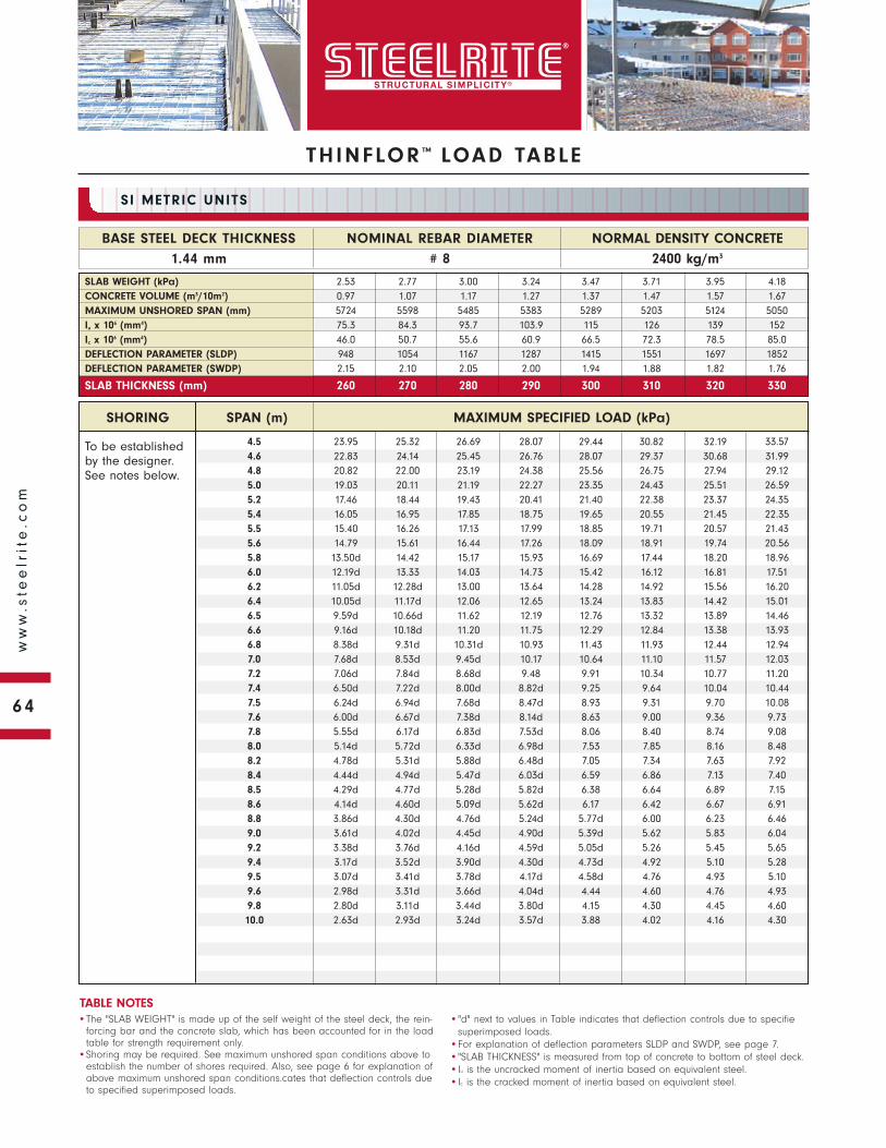
To be established by the designer. See notes below.
SHORING SPAN (m) MAXIMUM SPECIFIED LOAD (kPa)
NORMAL DENSITY CONCRETE
2400 kg/m3
BASE STEEL DECK THICKNESS
1.44 mm
NOMINAL REBAR DIAMETER
# 8
SI METRIC UNITS
•The "SLAB WEIGHT" is made up of the self weight of the steel deck, the rein-forcing bar and the concrete slab, which has been accounted for in the load table for strength requirement only.
•Shoring may be required. See maximum unshored span conditions above to establish the number of shores required. Also, see page 6 for explanation of above maximum unshored span conditions.cates that deflection controls due to specified superimposed loads.
•"d" next to values in Table indicates that deflection controls due to specifiesuperimposed loads.
•For explanation of deflection parameters SLDP and SWDP, see page 7.•"SLAB THICKNESS" is measured from top of concrete to bottom of steel deck.•Iu is the uncracked moment of inertia based on equivalent steel.•Ic is the cracked moment of inertia based on equivalent steel.
TABLE NOTES
SLAB WEIGHT (kPa) 2.53 2.77 3.00 3.24 3.47 3.71 3.95 4.18CONCRETE VOLUME (m3/10m2) 0.97 1.07 1.17 1.27 1.37 1.47 1.57 1.67MAXIMUM UNSHORED SPAN (mm) 5724 5598 5485 5383 5289 5203 5124 5050Iu x 106 (mm4) 75.3 84.3 93.7 103.9 115 126 139 152Ic x 106 (mm4) 46.0 50.7 55.6 60.9 66.5 72.3 78.5 85.0DEFLECTION PARAMETER (SLDP) 948 1054 1167 1287 1415 1551 1697 1852DEFLECTION PARAMETER (SWDP) 2.15 2.10 2.05 2.00 1.94 1.88 1.82 1.76
SLAB THICKNESS (mm) 260 270 280 290 300 310 320 330
4.5 23.95 25.32 26.69 28.07 29.44 30.82 32.19 33.574.6 22.83 24.14 25.45 26.76 28.07 29.37 30.68 31.994.8 20.82 22.00 23.19 24.38 25.56 26.75 27.94 29.125.0 19.03 20.11 21.19 22.27 23.35 24.43 25.51 26.595.2 17.46 18.44 19.43 20.41 21.40 22.38 23.37 24.355.4 16.05 16.95 17.85 18.75 19.65 20.55 21.45 22.355.5 15.40 16.26 17.13 17.99 18.85 19.71 20.57 21.435.6 14.79 15.61 16.44 17.26 18.09 18.91 19.74 20.565.8 13.50d 14.42 15.17 15.93 16.69 17.44 18.20 18.966.0 12.19d 13.33 14.03 14.73 15.42 16.12 16.81 17.516.2 11.05d 12.28d 13.00 13.64 14.28 14.92 15.56 16.206.4 10.05d 11.17d 12.06 12.65 13.24 13.83 14.42 15.016.5 9.59d 10.66d 11.62 12.19 12.76 13.32 13.89 14.466.6 9.16d 10.18d 11.20 11.75 12.29 12.84 13.38 13.936.8 8.38d 9.31d 10.31d 10.93 11.43 11.93 12.44 12.947.0 7.68d 8.53d 9.45d 10.17 10.64 11.10 11.57 12.037.2 7.06d 7.84d 8.68d 9.48 9.91 10.34 10.77 11.207.4 6.50d 7.22d 8.00d 8.82d 9.25 9.64 10.04 10.447.5 6.24d 6.94d 7.68d 8.47d 8.93 9.31 9.70 10.087.6 6.00d 6.67d 7.38d 8.14d 8.63 9.00 9.36 9.737.8 5.55d 6.17d 6.83d 7.53d 8.06 8.40 8.74 9.088.0 5.14d 5.72d 6.33d 6.98d 7.53 7.85 8.16 8.488.2 4.78d 5.31d 5.88d 6.48d 7.05 7.34 7.63 7.928.4 4.44d 4.94d 5.47d 6.03d 6.59 6.86 7.13 7.408.5 4.29d 4.77d 5.28d 5.82d 6.38 6.64 6.89 7.158.6 4.14d 4.60d 5.09d 5.62d 6.17 6.42 6.67 6.918.8 3.86d 4.30d 4.76d 5.24d 5.77d 6.00 6.23 6.469.0 3.61d 4.02d 4.45d 4.90d 5.39d 5.62 5.83 6.049.2 3.38d 3.76d 4.16d 4.59d 5.05d 5.26 5.45 5.659.4 3.17d 3.52d 3.90d 4.30d 4.73d 4.92 5.10 5.289.5 3.07d 3.41d 3.78d 4.17d 4.58d 4.76 4.93 5.109.6 2.98d 3.31d 3.66d 4.04d 4.44 4.60 4.76 4.939.8 2.80d 3.11d 3.44d 3.80d 4.15 4.30 4.45 4.6010.0 2.63d 2.93d 3.24d 3.57d 3.88 4.02 4.16 4.30
THINFLOR ™ LOAD TABLE
64
ww
w.s
tee
lrit
e.c
om
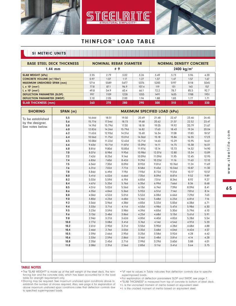
THINFLOR ™ LOAD TABLE
To be established by the designer. See notes below.
NORMAL DENSITY CONCRETE
2400 kg/m3
BASE STEEL DECK THICKNESS
1.44 mm
NOMINAL REBAR DIAMETER
# 9
SI METRIC UNITS
•The "SLAB WEIGHT" is made up of the self weight of the steel deck, the rein-forcing bar and the concrete slab, which has been accounted for in the load table for strength requirement only.
•Shoring may be required. See maximum unshored span conditions above to establish the number of shores required. Also, see page 6 for explanation of above maximum unshored span conditions.cates that deflection controls due to specified superimposed loads.
•"d" next to values in Table indicates that deflection controls due to specifiesuperimposed loads.
•For explanation of deflection parameters SLDP and SWDP, see page 7.•"SLAB THICKNESS" is measured from top of concrete to bottom of steel deck.•Iu is the uncracked moment of inertia based on equivalent steel.•Ic is the cracked moment of inertia based on equivalent steel.
TABLE NOTES
SLAB WEIGHT (kPa) 2.55 2.79 3.02 3.26 3.49 3.73 3.96 4.20CONCRETE VOLUME (m3/10m2) 0.97 1.07 1.17 1.27 1.37 1.47 1.57 1.67MAXIMUM UNSHORED SPAN (mm) 5714 5589 5477 5376 5283 5197 5118 5045Iu x 106 (mm4) 77.8 87.1 96.9 107.4 119 131 143 157Ic x 106 (mm4) 49.8 54.9 60.4 66.1 72.2 78.7 85.5 92.7DEFLECTION PARAMETER (SLDP) 997 1109 1228 1355 1491 1635 1788 1951DEFLECTION PARAMETER (SWDP) 2.10 2.05 2.00 1.94 1.88 1.83 1.77 1.71
SLAB THICKNESS (mm) 260 270 280 290 300 310 320 330
SHORING SPAN (m) MAXIMUM SPECIFIED LOAD (kPa)
5.5 16.64d 18.51 19.50 20.49 21.48 22.47 23.46 24.455.6 15.77d 17.54d 18.73 19.68 20.62 21.57 22.52 23.475.8 14.19d 15.79d 17.30 18.18 19.05 19.92 20.79 21.676.0 12.82d 14.26d 15.79d 16.82 17.63 18.43 19.24 20.046.2 11.62d 12.93d 14.31d 15.60 16.34 17.08 17.83 18.576.4 10.56d 11.75d 13.01d 14.36d 15.18 15.86 16.55 17.236.5 10.08d 11.22d 12.42d 13.71d 14.63 15.29 15.95 16.616.6 9.63d 10.71d 11.87d 13.09d 14.11 14.75 15.38 16.016.8 8.81d 9.80d 10.85d 11.97d 13.14 13.73 14.32 14.907.0 8.07d 8.98d 9.95d 10.98d 12.07d 12.80 13.34 13.897.2 7.42d 8.25d 9.14d 10.09d 11.09d 11.95 12.45 12.957.4 6.83d 7.60d 8.42d 9.29d 10.22d 11.16 11.63 12.107.5 6.56d 7.30d 8.09d 8.92d 9.81d 10.76d 11.24 11.697.6 6.31d 7.02d 7.77d 8.58d 9.43d 10.34d 10.87 11.307.8 5.84d 6.49d 7.19d 7.93d 8.72d 9.57d 10.17 10.578.0 5.41d 6.02d 6.66d 7.35d 8.09d 8.87d 9.52 9.898.2 5.02d 5.59d 6.19d 6.83d 7.51d 8.24d 8.92 9.278.4 4.67d 5.20d 5.76d 6.35d 6.99d 7.66d 8.36 8.688.5 4.51d 5.02d 5.56d 6.13d 6.74d 7.39d 8.09d 8.418.6 4.35d 4.84d 5.36d 5.92d 6.51d 7.14d 7.81d 8.148.8 4.06d 4.52d 5.01d 5.52d 6.08d 6.66d 7.29d 7.639.0 3.80d 4.23d 4.68d 5.16d 5.68d 6.23d 6.81d 7.169.2 3.56d 3.96d 4.38d 4.83d 5.32d 5.83d 6.38d 6.719.4 3.33d 3.71d 4.11d 4.53d 4.98d 5.47d 5.98d 6.309.5 3.23d 3.59d 3.98d 4.39d 4.83d 5.30d 5.79d 6.109.6 3.13d 3.48d 3.86d 4.25d 4.68d 5.13d 5.61d 5.919.8 2.94d 3.27d 3.62d 4.00d 4.40d 4.82d 5.28d 5.5410.0 2.77d 3.08d 3.41d 3.76d 4.14d 4.54d 4.97d 5.2010.2 2.61d 2.90d 3.21d 3.55d 3.90d 4.28d 4.68d 4.8810.4 2.46d 2.74d 3.03d 3.35d 3.68d 4.04d 4.42d 4.5710.5 2.39d 2.66d 2.95d 3.25d 3.58d 3.92d 4.28 4.4210.6 2.33d 2.59d 2.86d 3.16d 3.48d 3.81d 4.14 4.2810.8 2.20d 2.45d 2.71d 2.99d 3.29d 3.60d 3.88 4.0111.0 2.08d 2.31d 2.56d 2.83d 3.11d 3.41d 3.64 3.75
65
ww
w.s
tee
lrit
e.c
om
THINFLOR ™ NOTES
65
ww
w.s
tee
lrit
e.c
om
THINFLOR ™ NOTES
66
ww
w.s
tee
lrit
e.c
om
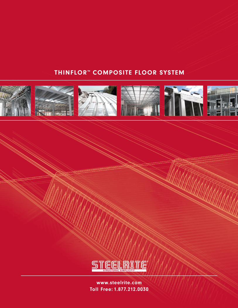
www.steelrite.comToll Free: 1.877.212.0030
THINFLOR™ COMPOSITE FLOOR SYSTEM


![Unitarity Triangle Analysis: Past, Present, Futurebenasque.org/benasque/2004quarks/2004quarks-talks/martin...sin 2 α = - 0.14 ± 0.25 sin 2 β = 0.697 ± 0.036 [ -0.62 - +0.33] [](https://img.pdfslide.net/doc/110x75/600a2801c0d1077a670d5abe/unitarity-triangle-analysis-past-present-sin-2-014-025-sin-2.jpg)