Embed Size (px)
Citation preview

www.energy.gov/EM 1
U.S. UNIVERSITY-LED INTEGRATED RESEARCH PROJECT
WEBINAR FOLLOW-UP – AUGUST 21, 2015
ADVANCED CAPABILITIES OF NUCLEARIZED ROBOTICS FOR INTEGRATED MAPPING (IRP-EM-1)

www.energy.gov/EM 2
Statement of Need
This IRP seeks a functional prototype of a robotic solution that will:
1) Remotely gain access to and maneuver within a high-hazard, physically challenged, confined, and unstructured space or area within a nuclear facility;
2) Obtain high-resolution color video footage;
3) Perform simultaneous localization and mapping;
4) Perform radiation and radioactivity measurements of alpha and beta particles as well as gamma rays as dictated by the radioisotope(s) expected to be present;
5) Perform appropriate non-destructive, in situ measurements of the materials of construction to help determine structural integrity; and
6) Integrate and correlate SLAM and radiation data for analysis, scientific visualization and computer simulation.

www.energy.gov/EM 3
Requirements
Proposals submitted in response to this IRP must:
(1) Indicate the intention for collaboration with at least one other US university/college having established robotics expertise and assets;
(2A) Indicate the intention for collaboration with at least one DOE national laboratory/technology center OR
(2B) Indicate the intention for collaboration with a laboratory/ technology center of another federal agency having established robotics expertise and assets;
(3) Demonstrate full functionality of the robotics system to meet the aforementioned technical objective at a field mock-up;
(4) Provide a strategy for advancing the robotic solution to the next phase of EM radioactive test bed demonstration; and
(5) Demonstrate utility at one of EM’s nuclear facilities.
www.energy.gov/EM 4
Representative Applications
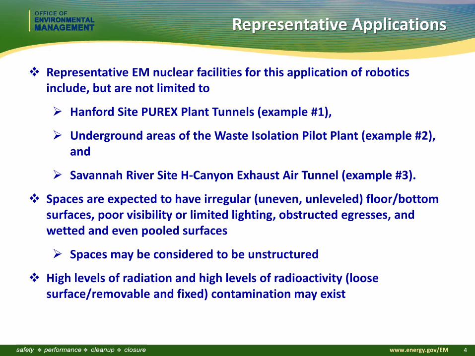
Representative EM nuclear facilities for this application of robotics include, but are not limited to
Hanford Site PUREX Plant Tunnels (example #1),
Underground areas of the Waste Isolation Pilot Plant (example #2), and
Savannah River Site H-Canyon Exhaust Air Tunnel (example #3).
Spaces are expected to have irregular (uneven, unleveled) floor/bottom surfaces, poor visibility or limited lighting, obstructed egresses, and wetted and even pooled surfaces
Spaces may be considered to be unstructured
High levels of radiation and high levels of radioactivity (loose surface/removable and fixed) contamination may exist

www.energy.gov/EM 5
Example #1: Hanford PUREX Plant
The Plutonium-Uranium Extraction (PUREX) Plant is located at the Hanford Site in eastern Washington. It operated from 1956 to 1972 and then from 1983 to 1991 for the recovery of uranium, plutonium and neptunium from irradiated reactor fuel via chemical separation.

www.energy.gov/EM 6
PUREX Storage Tunnels # 1 & 2 are used for storage of large failed and outworn PUREX process equipment
Remote access is needed for initial entry into the sealed tunnels for surveying and characterization
Tunnel #2
Hanford PUREX Plant Storage Tunnels

www.energy.gov/EM 7
Hanford PUREX Plant Storage Tunnels
The tunnels branch off from the railroad tunnel and extend southward from these the east end of the PUREX Plant
There are no electrical utilities, water lines, drains, fire detection or suppression systems, radiation monitoring, or communication systems provided inside the tunnels

www.energy.gov/EM 8
PUREX Tunnel #1
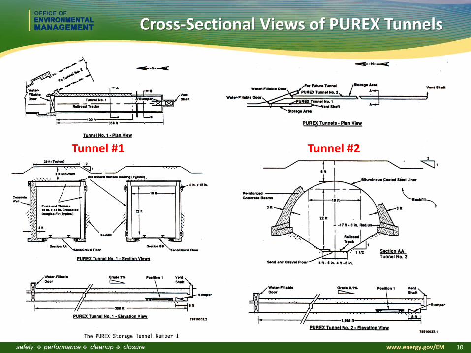
General construction Built in 1956 as part of the original PUREX Plant 19 feet wide, 358 feet long, and 22 feet high First 100 feet is 3-foot thick re-enforced concrete Remaining 258 feet is creosote pressure-treated Douglas fir timber Covered by 8 feet of earth fill Ventilation shaft is reinforced concrete
Storage area Eight railcars of highly radioactive failed process equipment occupy
and fill the tunnel Total volume of equipment is approx. 780 cubic yards Storage capacity is approx. 5,400 cubic yards

www.energy.gov/EM 9
PUREX Tunnel #2
General construction Added in 1964 34 feet wide, 1,688 feet long, and 26 feet high Made of steel and reinforced concrete Semi-circular shaped roof, supported by internal I-beam wales
attached to external, reinforced concrete arches Floor, outboard of the railroad ties, slopes upward to a height of
approx. 6 feet above the railroad bed Covered by 8 feet of earth fill Ventilation shaft is reinforced concrete
Storage area 28 railcars of highly radioactive failed process equipment occupy and
fill the tunnel Total volume of equipment is approx. 2,883 cubic yards Storage capacity is approx. 26,000 cubic yards
www.energy.gov/EM 10
Cross-Sectional Views of PUREX Tunnels
Tunnel #1 Tunnel #2

www.energy.gov/EM 11
Current PUREX Tunnels Status
Tunnels are sealed with no access points Possible entry via vent shafts
High levels of radiation inside tunnels Signage prohibits/restricts direct entry into tunnels
All utilities and ventilation systems are isolated or removed Annual external surveillances and inspections
Overall structural deterioration Subsidence Erosion of earth cover Ventilation stack seal/blank Monitor for radioactive contamination migration and changes in
radiation levels Remote access is needed for initial entry into the tunnels for surveying
and characterization

www.energy.gov/EM 12
Example #2: Waste Isolation Pilot Plant
Geological repository for the disposal of defense transuranic waste
Built in a 250-million-year old, nearly impermeable salt basin
Remote access is needed for emergency response, initial re-entry, trouble-shooting, and recovery, particularly when conditions are unknown

www.energy.gov/EM 13
WIPP Facility and Stratigraphic Sequence

www.energy.gov/EM 14
WIPP Typical Dimensions and Layouts
Typical Access Drifts: 40 ft. wide and 14 ft. high
Typical Panel Dimensions: 400 ft. wide and 1,115 ft. long
Typical Placement Configurations for
Contact-Handled TRU Waste Containers
Typical Room Dimensions: 33 ft. wide, 300 ft. long, 14 ft. high

www.energy.gov/EM 15
WIPP Current Configuration Status

www.energy.gov/EM 16
WIPP Operational Events
Two recent unplanned events highlighted the need for improved operational capabilities such as remote access for emergency response, initial re-entry, trouble-shooting, and recovery, particularly when conditions are unknown.

www.energy.gov/EM 17
WIPP Operational Events Recap
February 5, 2014 Truck Fire EIMCO Haul Truck 74-U-006B (salt haul truck) caught fire Believed to have originated in the truck’s engine compartment and involved
hydraulic fluid and/or diesel fuel that contacted hot surfaces on the truck, possibly the catalytic converter, and then ignited
86 workers in the mine (underground) were safely evacuated 13 workers treated for smoke inhalation
February 14, 2014 Radiological Incident A continuous air monitor detected airborne radiation in the underground The ventilation system automatically switched to high-efficiency particulate
air filtration mode when airborne radiation was detected Release is believed to have originated from a single waste drum within
which an exothermic reaction of incompatible materials occurred causing the drum to become over-pressurized, compromising the lid seal, and releasing radioactivity
No employees were in the underground at the time of the alarm

www.energy.gov/EM 18
WIPP Current Status
Waste emplacement operations have not resumed pending completion of a series of corrective actions Nuclear facility safety document being revised Safety management program undergoing revitalization Underground restoration continuing
Re-establish degraded equipment Fire protection Maintenance and ground control Radiological roll-back Soot cleaning of electrical panels
Mine stability being expedited – ground control/bolting Panel 6 and Panel 7, Room 7 closed Interim ventilation installation in progress Supplemental ventilation modifications being planned

www.energy.gov/EM 19
Example #3: Savannah River Site H-Canyon
H-Canyon is located on the Savannah River Site in Aiken, SC, and is a radio-chemical separation facility built to support the production of nuclear materials. Its main purpose was to reprocess spent uranium fuel and other enriched uranium fuels. H-Canyon began operations in 1955 and remains in operation today. It is an 835-feet long, multilevel facility and is referred to as a canyon because of its long, rectangular shape.

www.energy.gov/EM 20
H-Canyon Cross-Sectional View
Potentially contaminated air is pulled from the Hot and Warm Canyons, through air exhaust tunnels and a sand filter prior to being released into the atmosphere.
Remote access is needed for more comprehensive inspection, surveying, and characterization of the air tunnels.
The Hot and Warm Canyons each house a series of cells with concrete walls and cell covers. Work is performed remotely from a central control room using bridge cranes.
Crossover Tunnel Canyon Exhaust Tunnel Air Flow Air Flow

www.energy.gov/EM 21
SRS H-Canyon Air Tunnel: Past Inspections

www.energy.gov/EM 22
SRS H-Canyon Air Tunnel: Degradation is Observed
Over the last 60 years of operation, the interior surfaces of the reinforced concrete tunnel have been exposed to 25 to 40 mph air flows of moist, nitric acid-laden air
Interior surfaces of the tunnel have eroded away the top 2-inch layer of concrete exposing the inner layer of reinforcing steel
Exposed Bars Near Western Expansion

www.energy.gov/EM 23
SRS H-Canyon Air Tunnel: Effects of Degradation
Over the last 60 years of operation, degradation of the concrete has resulted in aggregate and debris being deposited on the floor
Water has also accumulated on some tunnel floor areas
Standing water Debris created uneven surface

www.energy.gov/EM 24
SRS H-Canyon Air Tunnel Summary
Past visual inspections revealed tunnel degradation
Tunnel spaces are expected to have high radiation levels (estimated to be 40 to 250 mrem/hr) and high levels of radioactivity
Air flow rates range from 25 to 40 mph of moist, nitric acid-laden vapor
Access to the air tunnels is limited
Concrete (mud-like) residue on most portions of the tunnel floor as thick as several inches
Standing water in some portions
Remote access is needed for more comprehensive inspection, surveying, and characterization of the air tunnels

www.energy.gov/EM 25
Other Examples: Savannah River Site Underground Radioactive Liquid Waste Tank
Remote access is needed to support surveying, characterization and inspection

www.energy.gov/EM 26
Other Examples: Recent Need at Hanford Underground Radioactive Liquid Waste Tank
Remote access is needed to support investigation and trouble-shooting in DSTs