Embed Size (px)
Citation preview

USB Magnetic Card ReaderV3TU SeriesUser's Manual
Thank you for purchasing OMRON Magnetic Card Reader.To use this product properly, read the Installation chapter contained inthe driver CD-ROM before connecting the card reader to the computer.
All Rights Reserved, Copyright (c) OMRON Corporation 2000
Rev. V3.1.5
Notice
(1) No part of this document may be reproduced in any form or by any means without permission.(2) Information in this document is subject to change without notice.(3) Every effort has been made to ensure the accuracy of this document. In case of any doubt,
however, send inquiries to the address listed at the end of this document.(4) In no event shall OMRON be liable for any loss, damage, or lost profit
resulting from the use of this product regardless of the items described above.(5) OMRON shall not assume any responsibility for the results of overseas use of this product.
Besides, OMRON does not provide maintenance or repair services overseas.(6) No part of the software may be copied, modified, or distributed without our permission.
The copyright of the present software and document belongs to OMRON Corporation.The US version of Microsoft Windows 98 is a registered trademark of Microsoft Corporation in theUnited States.

Safety Precautions
For safe and proper use/maintenance of this product, read and understand this manual carefully beforeusing the product.
After reading this manual, save it for later use.
This section provides important safety information. Make sure to heed it.OMRON will not assume any responsibility for any accident or the like resulting from failureto comply.
WARNINGCAUTION
Property damage means extensive damage to houses, household effects, domestic animals, or pets.
Major Symbols
The symbol indicates a caution (including a warning).Specific information is provided as messages or illustrations in or near the symbol.The example on the left indicates "Beware of electric shock."
This symbol indicates prohibition (don'ts).Specific information is provided as messages or illustrations in or near the symbol.The example on the left indicates "Do not disassemble."
The symbol indicates compulsion (a must).Specific information is provided as messages or illustrations in or near the symbol.The example on the left indicates "Turn off the power."
Other symbols: [General precaution]
Alerts you to conditions that may result in death or serious personnel injury.
Alerts you to conditions that may result in personnel injury or property damage.

WARNING
Do not install or use the product in wet locations. Also, never let any metal objector liquid get inside the product. Failure to comply may result in shock or firehazards.
Do not touch or operate the product with wet hands. Failure to comply may result inshock hazards.
Do not plug or unplug the USB connector with wet hands. Failure to comply mayresult in shock hazards.
CAUTION
Do not disassemble the product. Failure to comply may result in shock or firehazards.
Do not install the product in a location that is wet, steamy, dusty, or filled with oilmist. Non-compliance may result in shock hazards, fire hazards, or failures.
Do not use the product near strong magnetic fields, which may cause malfunctionsor failures.
Do not use the product in a location that is subject to intense vibrations, which maycause malfunctions or failures.
When performing maintenance on the product, unplug the USB cable from thecomputer to avoid shock hazards.

Checking the Contents of the Package
After unpacking the product, check that the following items are present.
1.Magnetic card reader: 1 unit
2.USB cable (approx. 2 m long): 1 piece
3.Driver CD-ROM: 1 piece
4.User's manual (this document): 1 copy
5.Installation manual: 1 copy

Contents
1. Introduction 1
Product OverviewSystem RequirementsNames and Functions of Parts
2. Installation 3
Installation
3. Card Reader Setup Procedures 7
Starting the Card Reader Setup ProgramSetting Operation ModesSpecifying Track DetailsFactory Default Settings
4. Method of Operation 14
How to Read a CardPC settingsHow to manipulate a cardResults of readingAbout LEDs and Buzzers
5. Troubleshooting 16
Troubleshooting
6. Maintenance 18
Cleaning the Card Reader
Appendix 19
About Command Control ModeMajor Specifications
- 1 -
1. Introduction
Product Overview
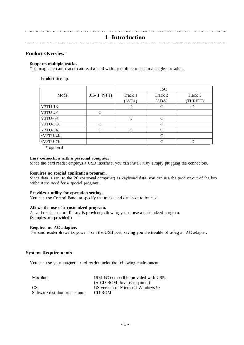
Supports multiple tracks.This magnetic card reader can read a card with up to three tracks in a single operation.
Product line-up
ISOModel JIS-II (NTT) Track 1 Track 2 Track 3
(IATA) (ABA) (THRIFT)V3TU-1K O O OV3TU-2K OV3TU-6K O OV3TU-DK O OV3TU-FK O O O*V3TU-4K O*V3TU-7K O O
* optional
Easy connection with a personal computer.Since the card reader employs a USB interface, you can install it by simply plugging the connectors.
Requires no special application program.Since data is sent to the PC (personal computer) as keyboard data, you can use the product out of the boxwithout the need for a special program.
Provides a utility for operation setting.You can use Control Panel to specify the tracks and data size to be read.
Allows the use of a customized program.A card reader control library is provided, allowing you to use a customized program.(Samples are provided.)
Requires no AC adapter.The card reader draws its power from the USB port, saving you the trouble of using an AC adapter.
System Requirements
You can use your magnetic card reader under the following environment.
Machine: IBM-PC compatible provided with USB.(A CD-ROM drive is required.)
OS: US version of Microsoft Windows 98Software-distribution medium: CD-ROM

- 2 -
Names and Functions of Parts
OK/ERR LED
PWR/BUSY LED
USB connector for connection with PC
USB cable (2 m long)
Card travel direction mark
USB connector for connectionwith main unit
Front
Slide groove
Main unit
RearUSB port
Main unit Main unit of the magnetic card readerSlide groove Used to slide the magnetic card for reading.
(For details, refer to "Method of Operation" later in this manual.)PWR/BUSY LED Indicates the status of the card reader by color.
(For details, refer to "Method of Operation" later in this manual.)OK/ERR LED Indicates the result of reading by color.
(For details, refer to "Method of Operation" later in this manual.)Buzzer Sounds when a card is read.
(For details, refer to "Method of Operation" later in this manual.)USB port Used to insert the reader-side connector of the furnished USB
cable.USB cable Connects the main unit with a PC. The two ends (on the PC side(approx. 2 m long) and card reader side) of the cable are provided with connectors of
different shapes.

- 3 -
2. Installation
Installation
To install the card reader, proceed as follows.
(1) Start the PC (personal computer) without connecting the card reader.
(2) When Microsoft Windows 98 (US version) starts up successfully, connect the card reader to the PC.
Insert the connector securely.
To the USB port of the PC
Do not plug and unplug the USB cable instantaneously. That may result in malfunctions.Caution:

- 4 -
(3) When the card reader is recognized, a dialog box (wizard) that looks like the one shown below appearsand the installation of the necessary drivers starts.
There is a total of three drivers to be installed. (Their names and sequence of installationmay change.)USB composite device (Topre USB Device)Unknown device (Topre USB Card Reader)USB Human Interface Device(Topre HID Keyboard Emulation)
three times.To install the drivers for the devices listed above, repeat Steps (3) to (7)
Insert the furnished CD-ROM (driver CD-ROM) in the CD-ROM drive of the personal computerand press the Next button on the wizard.
(4) The Add New Hardware wizard prompts you to select the method of searching for a driver.
Select the "Search for the best driver for your device" option and click the Next button.

- 5 -
(5) Specify the drive where the driver can be found.
Select the "CD-ROM drive" option and click the Next button.
You may be prompted to insert the Windows 98 CD-ROM as shown below.
After files are copied from the Windows 98 CD-ROM, make sure to insert the driver CD-ROMOtherwise, Your PC may fail to operate properly. The proper time to insert the CD-ROM is whenthe Add New Hardware wizard appears in Step (3).
(6) Now the Windows is ready to install the driver.
One of the following devicenames is displayed.
Topre USB DeviceTopre USB Card ReaderTopre HID Keyboard Emulation
Click the Next button.

- 6 -
(7) Now the driver installation is complete.
Click the Finish button.
(8) Repeat Steps (3) to (7) three times and finish the installation.
Now you can use your card reader. However, make detailed settings by selecting the Card Readericon form the Control Panel.
Example of how to start Card Reader Setup program
Click [Start] -> Click [Settings] -> Click [Control Panel] -> Double-click the [Card Reader] icon.
For details, refer to the next chapter "Card Reader Setup Procedures."

- 7 -
3. Card Reader Setup Procedures
Starting the Card Reader Setup Program
Click menu commands in the following order: [Start] -> [Settings] -> [Control Panel]
Double-click this icon.
Double-click the [Card Reader] icon to start the program.

- 8 -
The Card Reader Properties dialog box appears.
Displays the name of the card readerconnected.Format: Product name (track) -- Identification
No.
Disabled if no card reader is selected. (If onlyone card reader is connected, it is selectedautomatically.)
Displays the name of the connectedcard reader anew.
Finishes setting.
Select the card reader to set up, by clicking its name.If only one card reader is connected, it is selected automatically.
Confirms the existence of the selected cardreader by a LED and buzzer sound.
Used to set up the selected card reader.

- 9 -
Setting Operation Modes
Operation mode settings apply to the entire card reader.The settings are registered in the card reader and remain effective in the subsequent uses of the cardreader.
Displays the Operation Mode Setting page Displays device information
Displays the ISO1 Setting pageDisplays the ISO 2 Setting page
Displays the ISO 3 Setting page
The options in the dottedbox are effective only in the
Switches between keyboard emulation modeoperation modes
Saves the settings without closing the pageSaves the settings and returns to the previous screen
Returns to the previous screen without saving the settings
Keyboard Emulation mode / Command Control mode
Specify the operation mode of the card reader. If you want to capture card data in the keyboardinput format, select the Keyboard Emulation mode. If you want to use a special program for datacapture, select the Command Control mode.
Keyboard type to be emulated
Specify the keyboard type you are using currently. The data from the card reader is sentas keyboard data of the selected keyboard type. This setting does not apply to the CommandControl mode.
Shortcut to kana input mode
If you are using a Japanese keyboard, a shortcut key (key combination) is available to switch tokana input mode instead of using the Japanese input function (FEP). Select a desired combination.This setting does not apply to the Command Control mode.

- 10 -
Numeric data
Some applications accept only the numeric characters entered from a numeric keypad. When usingsuch an application, select the "Use numeric keypad" option.This setting does not apply to the Command Control mode.
Transmission rate
Depending on the throughput of a PC or structure of an application, data may not be received if itis transmitted too fast. In that case, slow down the transmission speed.This setting does not apply to the Command Control mode.

- 11 -
Specifying Track Details
You can make settings for each card track. The tabs displayed on the panel varies with the card readermodel. The settings are registered in the card reader and remain effective in the subsequent uses of thecard reader.
Specify whether you want to read this trackClick the desired track
Restores the default value ofReading position the reading position
Leading character
Trailing character
Saves the settings without closing the pageSaves the settings and returns to the previous screen
Returns to the previous screen without saving the settings
Read this track
Check this option if you want to read this track. You cannot read a single-track card witha three-track card reader because the remaining two tracks result in reading errors. In that case,deselect this option for the remaining two tracks.This setting does not apply to the Command Control mode.
Start position of reading
This field specifies the start position of reading on the given card track for data transfer to the PC.Use this option if you want to send only a part of card data to the PC.This setting does not apply to the Command Control mode.
End position of reading
This field specifies the end position of reading on the given card track for data transfer to thePC. Use this option if you want to send only a part of card data to the PC.This setting does not apply to the Command Control mode.

- 12 -
Leading character
Specify the characters you want to add to the head of data when, for example, you intend to use thedata on a spreadsheet program. These characters are sent to the PC before the card data. Frequentlyused characters are listed in the combo box. As to other characters, check the "Other" option andenter desired characters from the keyboard.This setting does not apply to the Command Control mode.
Trailing character
Specify the characters you want to add to the end of data when, for example, you intend to use thedata on a spreadsheet program. These characters are sent to the PC before the card data. Frequentlyused characters are listed in the combo box. As to other characters, check the "Other" option andenter desired characters from the keyboard.

- 13 -
Factory Default Settings
Operation mode Operation mode Keyboard Emulation mode
Keyboard to be emulated 106-key Japanese keyboard
Shortcut to kana input mode Ctrl + Caps Lock
Numeric data input Use full keyboard
Transmission rate Fastest
Track details JIS II (NTT) Read this track Yes
Start position 2
End position 70
Leading character Do not add
Trailing character Add a line feed
ISO-1 (IATA) Read this track Yes
Start position 2
End position 77
Leading character Do not add
Trailing character Add a line feed
ISO-2 (ABA) Read this track Yes
Start position 2
End position 38
Leading character Do not add
Trailing character Add a line feed
ISO-3 (THRIFT) Read this track Yes
Start position 2
End position 105
Leading character Do not add
Trailing character Add a line feed
- 14 -
4. Method of Operation.
How to Read a Card
(1) PC settings
Before reading a card, specify the following settings for the PC (personal computer).
Kanji input by kana-kanji conversion (the Japanese word input mode activated generally by pressingthe Alt + Kanji keys): OFFKatakana input: OFFNum Lock: ONCaps Lock: OFFScroll Lock: OFF
In the keyboard emulation mode, start an application that will receive the data read from the card andwill display keyboard entries. If you do not have a specific application, start Notepad that can acceptkeyboard entries.
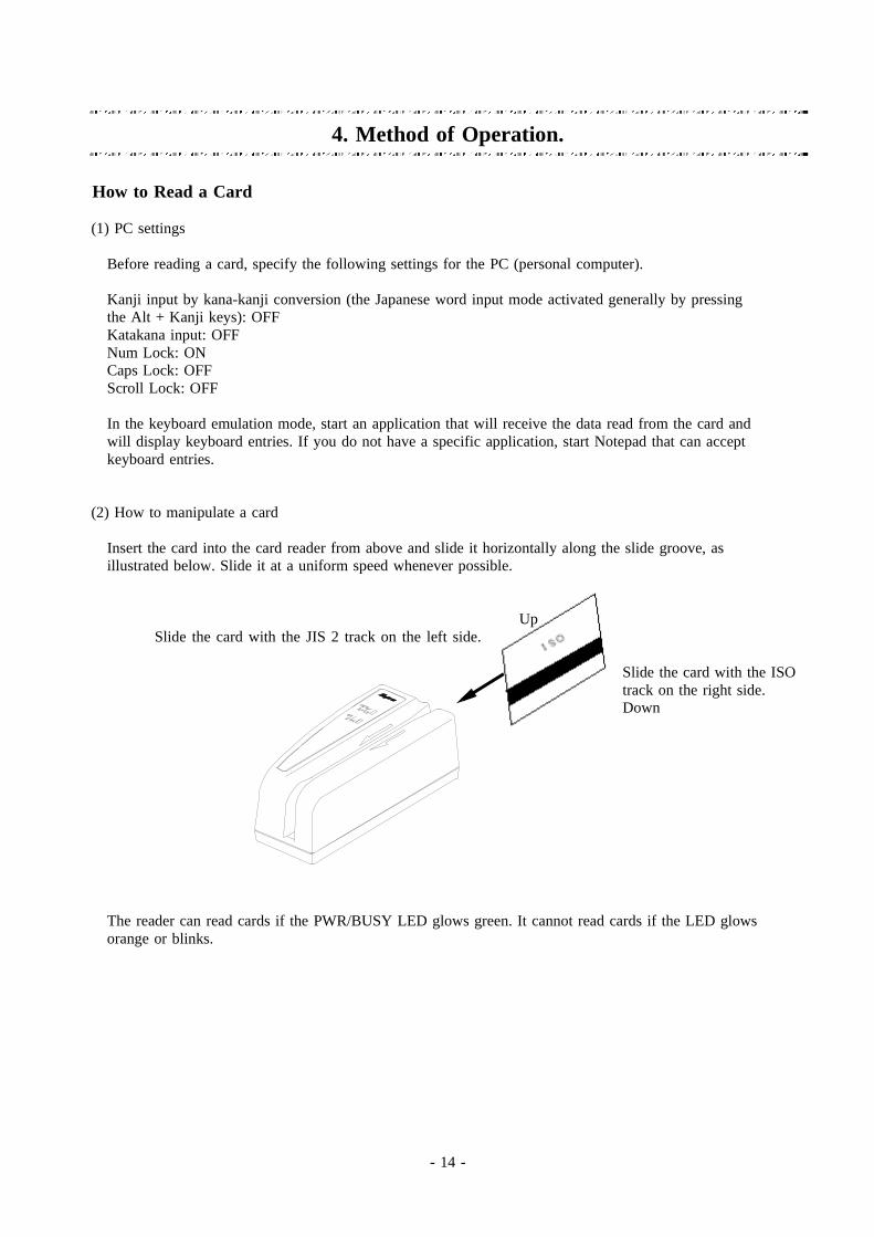
(2) How to manipulate a card
Insert the card into the card reader from above and slide it horizontally along the slide groove, asillustrated below. Slide it at a uniform speed whenever possible.
UpSlide the card with the JIS 2 track on the left side.
Slide the card with the ISOtrack on the right side.Down
The reader can read cards if the PWR/BUSY LED glows green. It cannot read cards if the LED glowsorange or blinks.
- 15 -
(3) Results of reading
If data was read successfully, the buzzer beeps once, the OK/ERR LED glows green, and the card data isdisplayed on the active editor.
If data could not be read successfully, the buzzer beeps three times, the OK/ERR LED glows red, and nocard data is displayed. Review the previous section "How to Read a Card" and read the card again. If thecard still cannot be read successfully, check against Chapter 3 "Card Reader Setup Procedures." If thesettings are correct, check whether the card is correct.
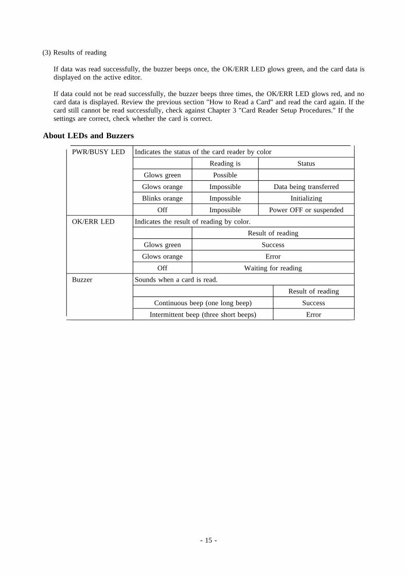
About LEDs and Buzzers
PWR/BUSY LED Indicates the status of the card reader by colorReading is Status
Glows green PossibleGlows orange Impossible Data being transferredBlinks orange Impossible Initializing
Off Impossible Power OFF or suspendedOK/ERR LED Indicates the result of reading by color.
Result of readingGlows green SuccessGlows orange Error
Off Waiting for readingBuzzer Sounds when a card is read.
Result of readingContinuous beep (one long beep) Success
Intermittent beep (three short beeps) Error
- 16 -
5. Troubleshooting
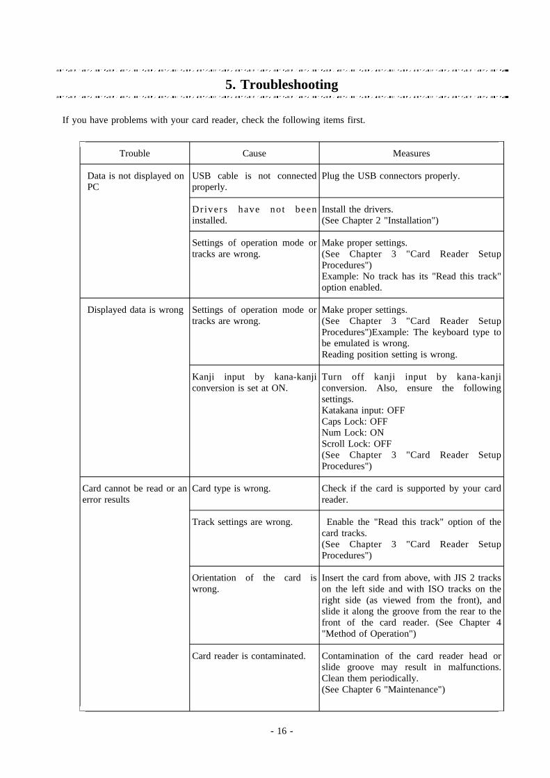
If you have problems with your card reader, check the following items first.
Trouble Cause Measures
Data is not displayed on USB cable is not connected Plug the USB connectors properly.PC properly.
Dr ivers have not been Install the drivers.installed. (See Chapter 2 "Installation")
Settings of operation mode or Make proper settings.tracks are wrong. (See Chapter 3 "Card Reader Setup
Procedures")Example: No track has its "Read this track"option enabled.
Displayed data is wrong Settings of operation mode or Make proper settings.tracks are wrong. (See Chapter 3 "Card Reader Setup
Procedures")Example: The keyboard type tobe emulated is wrong.Reading position setting is wrong.
Kanji input by kana-kanji Turn off kanji input by kana-kanjiconversion is set at ON. conversion. Also, ensure the following
settings.Katakana input: OFFCaps Lock: OFFNum Lock: ONScroll Lock: OFF(See Chapter 3 "Card Reader SetupProcedures")
Card cannot be read or an Card type is wrong. Check if the card is supported by your carderror results reader.
Track settings are wrong. Enable the "Read this track" option of thecard tracks.(See Chapter 3 "Card Reader SetupProcedures")
Orientation of the card is Insert the card from above, with JIS 2 trackswrong. on the left side and with ISO tracks on the
right side (as viewed from the front), andslide it along the groove from the rear to thefront of the card reader. (See Chapter 4"Method of Operation")
Card reader is contaminated. Contamination of the card reader head orslide groove may result in malfunctions.Clean them periodically.(See Chapter 6 "Maintenance")

- 17 -
Trouble Cause Measures
PC does not operate PC or card reader may not be Try the following measures: unplug the USBproperly: e.g., it does not in proper condition. cable and plug it again, or restart the PC.read cards. This may work in some cases. However, do
not plug and unplug the USB cableinstantaneously. Doing that may causemalfunctions.

- 18 -
6. Maintenance
Cleaning the Card Reader
Contamination of the card reader head or slide groove with oil or other foreign matter may result inmalfunctions or errors. Maintenance is performed to prevent or deal with them.
1.Cleaning fluid
Moisten the felt portion of a cleaning card with a cleaning fluid such as CFC, ethanol, or methanol andshake off any excess fluid.
2.Method
Slide the cleaning card along the slide groove about five times with the felt side facing the readinghead. Then leave the card reader about five minutes before use.
3.Frequency
Clean the card reader after every 500 to 1000 passes of magnetic cards or if errors occur repeatedly.
4.Precautions
Do not use a cleaning card if
its felt portion is peeling,its felt portion is conspicuously napped,it is warped 3 mm or more, orit is conspicuously contaminated.
For information on how to purchase cleaning cards, contact our sales department.

- 19 -
Appendix
About Command Control Mode
The Command Control mode works only with user applications. As a reference for preparation of userapplications, the driver CD-ROM contains a library and samples (their operation has been verified withVisual Basic Ver. 5 and Visual C++ Ver. 5) created by using the library.
Directory structure of driver CD-ROM
Root directory Contains all the drivers for the card reader including thesetup file and configuration file.
Library: DLLs and specifications (in the PDF format) for use incontrolling the card reader in the Command Control mode.
VBSample Command control sample programs created in Visual Basic.
Release Executable files of sample programs.
VCSample Command control sample programs created in Visual C.
Release Executable files of sample programs.
Acrobat4 A utility for reading Acrobat PDF files. (Start the ar40eng.exe program.)
Note: OMRON will not assume any responsibility for the results of using the sample source codes.Evaluate them carefully on your own before using them.

- 20 -
Major Specifications
Supported cards Magnetic card standards ID-1 card compliant with ISO 7810 and7811-1 to -5ID-1 card compliant with JIS X 6301 (1998)ID-1 card and identification card with a magneticstripe on front face (attached document),compliant with JIS X 6302 (1998)
Recording method F2F frequency modulationTrack Up to 3 tracks of the JIS II, ISO-1, ISO-2, or
ISO-3 typeReading rate 100 to 1000 mm/s
Interface Interface USB 1.0 compatibleConnector USB series B connectorConnecting cable Shielded USB cable 2 m long (supplied)Transfer method Interrupt transferTransfer rate Low speed 12 MbpsData transfer mode Keyboard emulation or Command control
OS Windows 98 (US version)Driver type WDM (Windows Driver Model)Device class Keyboard Emulation mode HID (Human Interface Device)
Command Control mode Vendor classPilot lamp LED lamp -- PWR (green) / BUSY (orange); OK (green) / ERR (red)Buzzer Piezoelectric buzzerReader life 300,000 passesEnvironment Operating temperature range 0 to 40 C
Operating humidity range 30 to 80 % RH (no condensing)Storage temperature range -15 to 60 CStorage humidity range 20 to 90 % RH (no condensing)
Power supply Supplied through USB interface (bus power)Operating voltage 4.40 to 5.25 VPower consumption During operation 50 mA (typ), 100 mA (max)
During stand-by 300 uA (typ), 500 uA (max)Weight 130 g (excluding accessories)Outside dimensions Approx. 55 (W) x 39.5 (H) x 120 (D) mm
- 21 -
If you have any question concerning use of the product, contact us at the following address.
Contact address
CARD READER COMPONENTS DEPARTMENT,OMRON CorporationGATE CITY OHSAKI, WEST TOWER 14F,1-11-1, OHSAKI, SHINAGAWA-KU,TOKYO, 141-0032 JAPANPHONE: +81-3-5435-2013FAX : +81-3-5435-2017