Embed Size (px)
Citation preview

Hardware-Description
November
USB-MINI-STICKS
2013
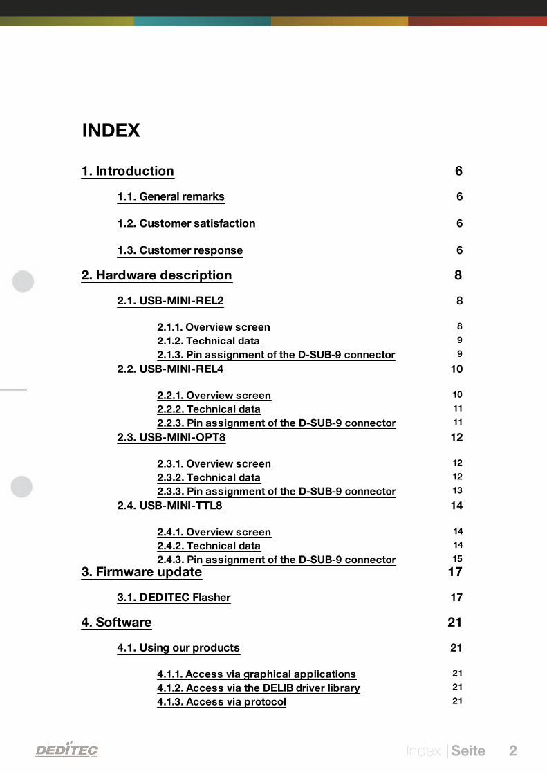
INDEX
Index | 2Seite
1. Introduction 6
1.1. General remarks 6
1.2. Customer satisfaction 6
1.3. Customer response 6
2. Hardware description 8
2.1. USB-MINI-REL2 8
82.1.1. Overview screen 92.1.2. Technical data 92.1.3. Pin assignment of the D-SUB-9 connector
2.2. USB-MINI-REL4 10
102.2.1. Overview screen 112.2.2. Technical data 112.2.3. Pin assignment of the D-SUB-9 connector
2.3. USB-MINI-OPT8 12
122.3.1. Overview screen 122.3.2. Technical data 132.3.3. Pin assignment of the D-SUB-9 connector
2.4. USB-MINI-TTL8 14
142.4.1. Overview screen 142.4.2. Technical data 152.4.3. Pin assignment of the D-SUB-9 connector
3. Firmware update 17
3.1. DEDITEC Flasher 17
4. Software 21
4.1. Using our products 21
214.1.1. Access via graphical applications 214.1.2. Access via the DELIB driver library 214.1.3. Access via protocol
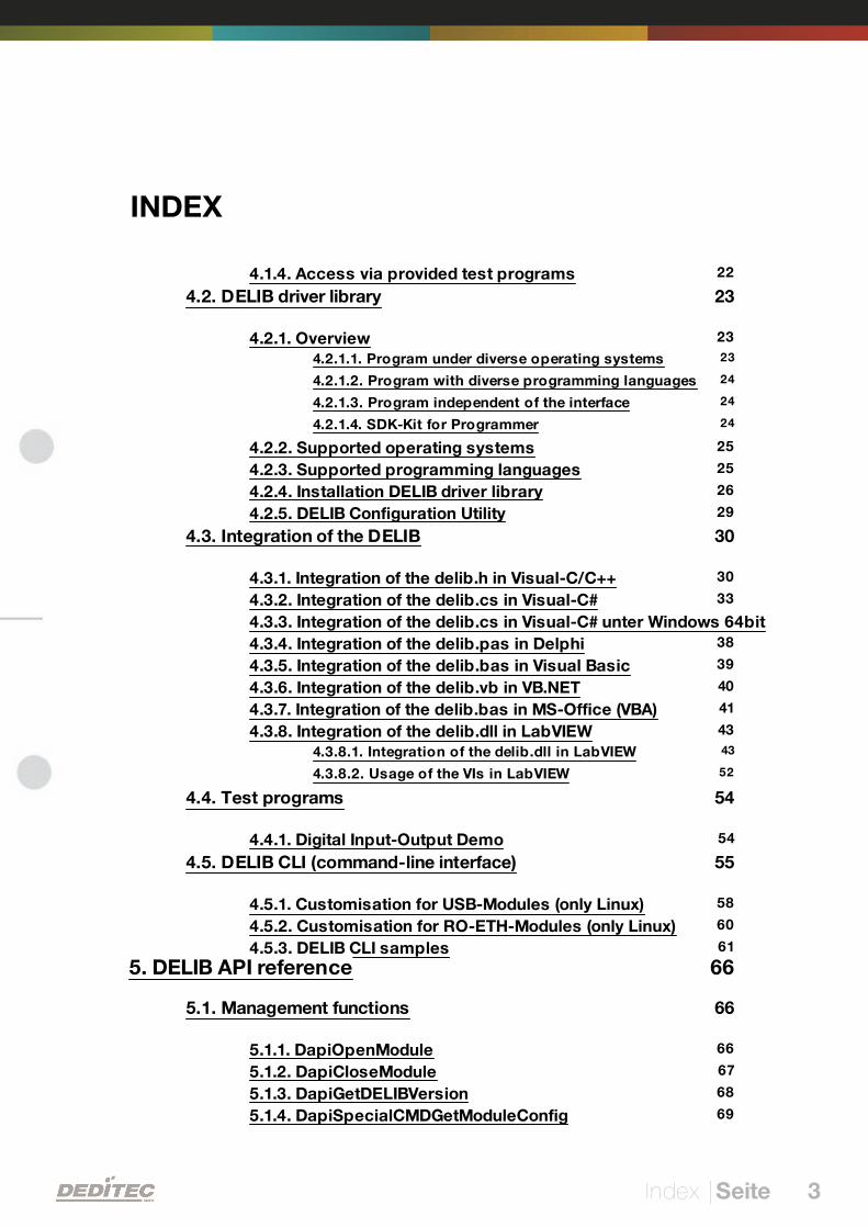
INDEX
Index | 3Seite
224.1.4. Access via provided test programs
4.2. DELIB driver library 23
234.2.1. Overview 234.2.1.1. Program under diverse operating systems
244.2.1.2. Program with diverse programming languages
244.2.1.3. Program independent of the interface
244.2.1.4. SDK-Kit for Programmer
254.2.2. Supported operating systems 254.2.3. Supported programming languages 264.2.4. Installation DELIB driver library 294.2.5. DELIB Configuration Utility
4.3. Integration of the DELIB 30
304.3.1. Integration of the delib.h in Visual-C/C++ 334.3.2. Integration of the delib.cs in Visual-C# 344.3.3. Integration of the delib.cs in Visual-C# unter Windows 64bit 384.3.4. Integration of the delib.pas in Delphi 394.3.5. Integration of the delib.bas in Visual Basic 404.3.6. Integration of the delib.vb in VB.NET 414.3.7. Integration of the delib.bas in MS-Office (VBA) 434.3.8. Integration of the delib.dll in LabVIEW 434.3.8.1. Integration of the delib.dll in LabVIEW
524.3.8.2. Usage of the VIs in LabVIEW
4.4. Test programs 54
544.4.1. Digital Input-Output Demo
4.5. DELIB CLI (command-line interface) 55
584.5.1. Customisation for USB-Modules (only Linux) 604.5.2. Customisation for RO-ETH-Modules (only Linux) 614.5.3. DELIB CLI samples
5. DELIB API reference 66
5.1. Management functions 66
665.1.1. DapiOpenModule 675.1.2. DapiCloseModule 685.1.3. DapiGetDELIBVersion 695.1.4. DapiSpecialCMDGetModuleConfig
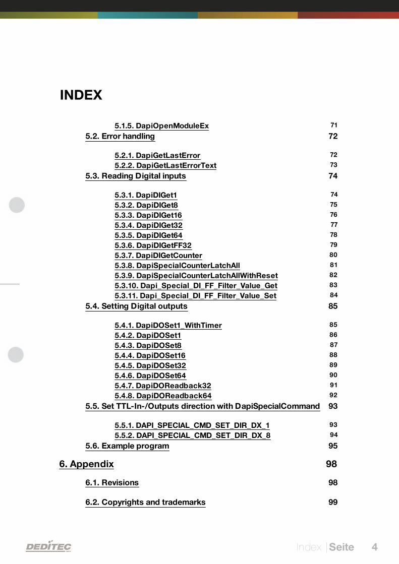
INDEX
Index | 4Seite
715.1.5. DapiOpenModuleEx
5.2. Error handling 72
725.2.1. DapiGetLastError 735.2.2. DapiGetLastErrorText
5.3. Reading Digital inputs 74
745.3.1. DapiDIGet1 755.3.2. DapiDIGet8 765.3.3. DapiDIGet16 775.3.4. DapiDIGet32 785.3.5. DapiDIGet64 795.3.6. DapiDIGetFF32 805.3.7. DapiDIGetCounter 815.3.8. DapiSpecialCounterLatchAll 825.3.9. DapiSpecialCounterLatchAllWithReset 835.3.10. Dapi_Special_DI_FF_Filter_Value_Get 845.3.11. Dapi_Special_DI_FF_Filter_Value_Set
5.4. Setting Digital outputs 85
855.4.1. DapiDOSet1_WithTimer 865.4.2. DapiDOSet1 875.4.3. DapiDOSet8 885.4.4. DapiDOSet16 895.4.5. DapiDOSet32 905.4.6. DapiDOSet64 915.4.7. DapiDOReadback32 925.4.8. DapiDOReadback64
5.5. Set TTL-In-/Outputs direction with DapiSpecialCommand 93
935.5.1. DAPI_SPECIAL_CMD_SET_DIR_DX_1 945.5.2. DAPI_SPECIAL_CMD_SET_DIR_DX_8
5.6. Example program 95
6. Appendix 98
6.1. Revisions 98
6.2. Copyrights and trademarks 99
I
Introduction | Seite 5
Introduction
Introduction | Seite 6
1. Introduction
1.1. General remarks
First of all, we would like to congratulate you to the purchase of a high qualityDEDITEC product.
Our products are being developed by our engineers according to qualityrequirements of high standard. Already during design and development we takecare that our products have -besides quality- a long availability and an optimalflexibility.
Modular design
The modular design of our products reduces the time and the cost ofdevelopment. Therefor we can offer you high quality products at a competitiveprice.
Availability
Because of the modular design of our products, we have to redesign only amodule instead of the whole product, in case a specific component is no longeravailable.
1.2. Customer satisfaction
Our philosophy: a content customer will come again. Therefor customersatisfaction is in first place for us.
If by any chance, you are not content with the performance of our product,please contact us by phone or mail immediately.
We take care of the problem.
1.3. Customer response
Our best products are co-developments together with our customers. Thereforwe are thankful for comments and suggestions.
II
Hardware description | Seite 7
Hardware description
Hardware description | Seite 8
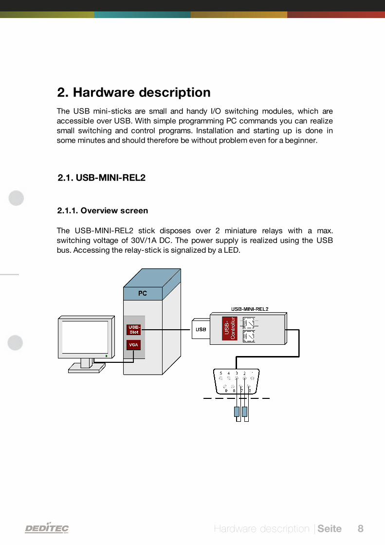
2. Hardware description
The USB mini-sticks are small and handy I/O switching modules, which areaccessible over USB. With simple programming PC commands you can realizesmall switching and control programs. Installation and starting up is done insome minutes and should therefore be without problem even for a beginner.
2.1. USB-MINI-REL2
2.1.1. Overview screen
The USB-MINI-REL2 stick disposes over 2 miniature relays with a max.switching voltage of 30V/1A DC. The power supply is realized using the USBbus. Accessing the relay-stick is signalized by a LED.
Hardware description | Seite 9
2.1.2. Technical data
USB-stick output module with USB 2.0 / USB1.1 interface
2 galvanically isolated relay-outputs (closing relays)
Max. switching voltage: 30V AC/DC
Max. switching current: 0,3A at 30V AC / 1A at 24V DC
LED access control on the USB stick
Connecting cable (approx. 1,8m) with D-SUB9 connector
Dimensions: 84,5 * 21 * 12,5/9,5 mm (without cable)
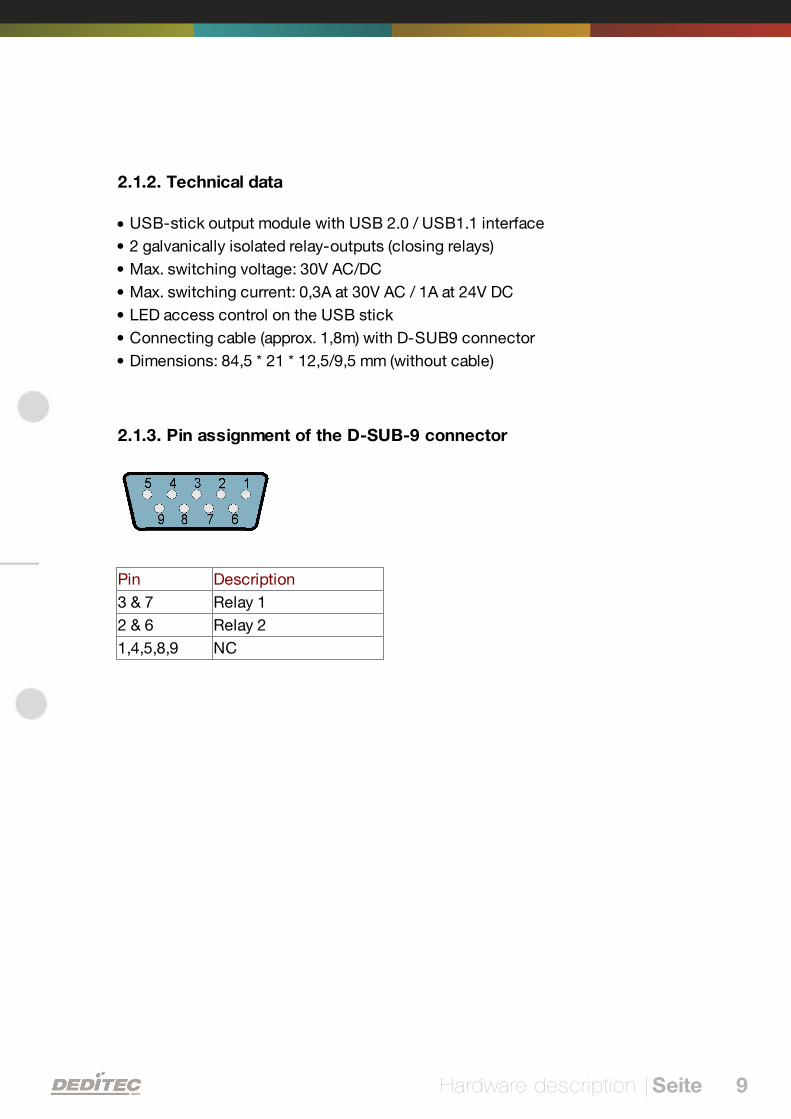
2.1.3. Pin assignment of the D-SUB-9 connector
Pin Description
3 & 7 Relay 1
2 & 6 Relay 2
1,4,5,8,9 NC
Hardware description | Seite 10
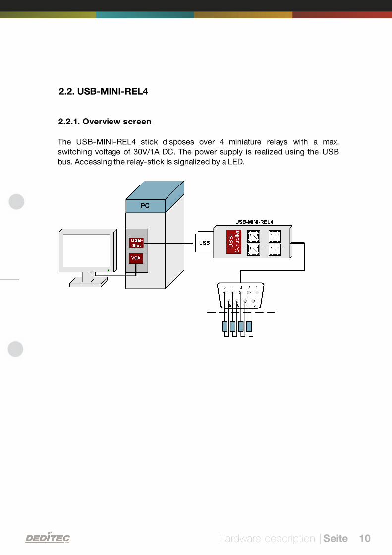
2.2. USB-MINI-REL4
2.2.1. Overview screen
The USB-MINI-REL4 stick disposes over 4 miniature relays with a max.switching voltage of 30V/1A DC. The power supply is realized using the USBbus. Accessing the relay-stick is signalized by a LED.
Hardware description | Seite 11
2.2.2. Technical data
USB-stick output module with USB 2.0 / USB1.1 interface
4 galvanically isolated relay-outputs (closing relays)
Max. switching voltage: 30V AC/DC
Max. switching current: 0,3A at 30V AC / 1A at 24V DC
LED access control on the USB stick
Connecting cable (approx. 1,8m) with D-SUB9 connector
Dimensions: 84,5 * 21 * 12,5/9,5 mm (without cable)
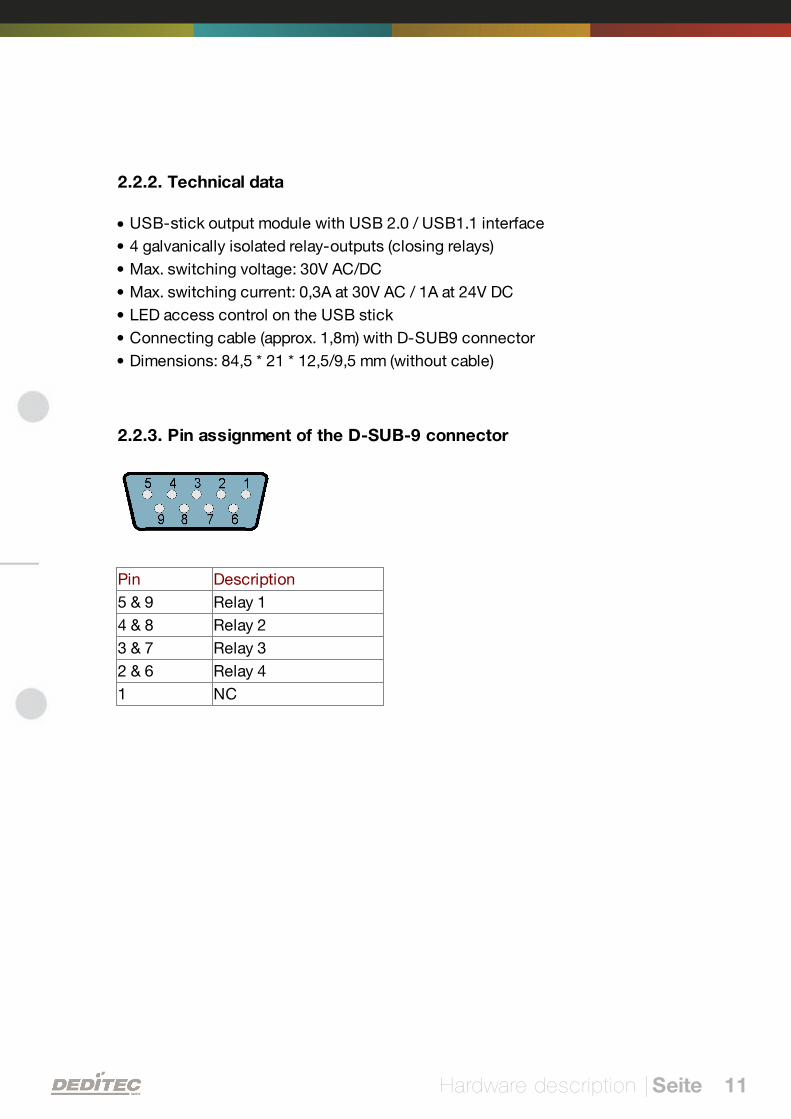
2.2.3. Pin assignment of the D-SUB-9 connector
Pin Description
5 & 9 Relay 1
4 & 8 Relay 2
3 & 7 Relay 3
2 & 6 Relay 4
1 NC

Hardware description | Seite 12
2.3. USB-MINI-OPT8
2.3.1. Overview screen
The USB-MINI-OPT8 stick offers up to 8 optically decoupled inputs. The powersupply is realized using the USB bus. Accessing the relay-stick is signalized bya LED.
2.3.2. Technical data
USB stick input module with USB 2.0 / USB1.1 interface
8 galvanically decoupled optocoupler inputs
Input voltage range: 5V-12V AC / DC
LED access control on the USB stick
Connecting cable (approx. 1,8m) with D-SUB9 connector
Dimensions: 84,5 * 21 * 12,5/9,5 mm (without cable)
Hardware description | Seite 13
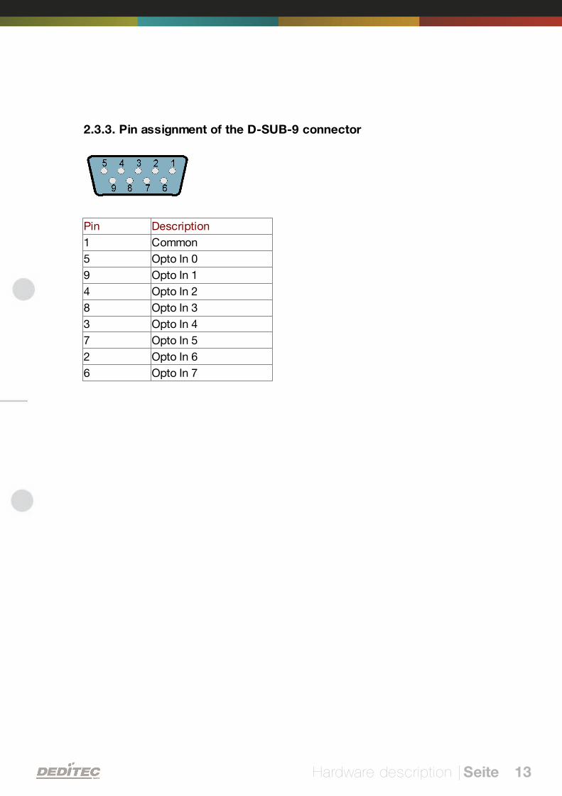
2.3.3. Pin assignment of the D-SUB-9 connector
Pin Description
1 Common
5 Opto In 0
9 Opto In 1
4 Opto In 2
8 Opto In 3
3 Opto In 4
7 Opto In 5
2 Opto In 6
6 Opto In 7
Hardware description | Seite 14
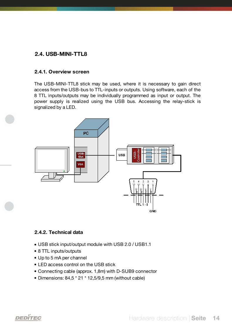
2.4. USB-MINI-TTL8
2.4.1. Overview screen
The USB-MINI-TTL8 stick may be used, where it is necessary to gain directaccess from the USB-bus to TTL-inputs or outputs. Using software, each of the8 TTL inputs/outputs may be individually programmed as input or output. Thepower supply is realized using the USB bus. Accessing the relay-stick issignalized by a LED.
2.4.2. Technical data
USB stick input/output module with USB 2.0 / USB1.1
8 TTL inputs/outputs
Up to 5 mA per channel
LED access control on the USB stick
Connecting cable (approx. 1,8m) with D-SUB9 connector
Dimensions: 84,5 * 21 * 12,5/9,5 mm (without cable)
Hardware description | Seite 15
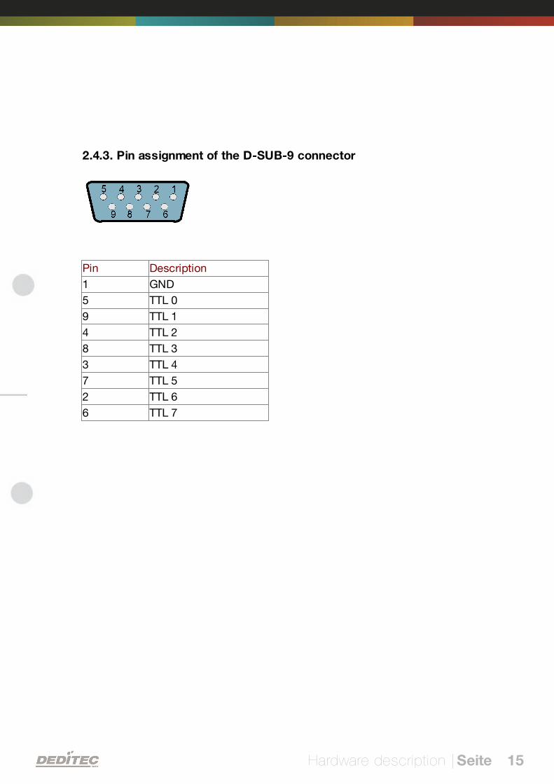
2.4.3. Pin assignment of the D-SUB-9 connector
Pin Description
1 GND
5 TTL 0
9 TTL 1
4 TTL 2
8 TTL 3
3 TTL 4
7 TTL 5
2 TTL 6
6 TTL 7
III
Firmware update | Seite 16
Firmware update
Firmware update | Seite 17
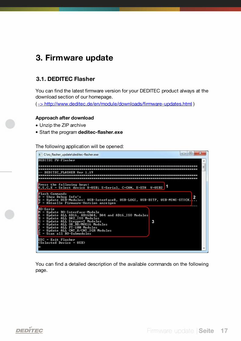
3. Firmware update
3.1. DEDITEC Flasher
You can find the latest firmware version for your DEDITEC product always at thedownload section of our homepage.
( -> http://www.deditec.de/en/module/downloads/firmware-updates.html )
Approach after download
Unzip the ZIP archive
Start the program deditec-flasher.exe
The following application will be opened:
You can find a detailed description of the available commands on the followingpage.

Firmware update | Seite 18
1. Select the Interface of the module of the RO-Series
Command (Key) Interface
U USB-Interface
S Serial Interface (RS-232 / RS-485)
C CAN-Interface
E Ethernet-Interface
V USB2-Interface
Note:
1) The current selected interface will be displayed in the last line (Selected
Device = USB)
2) Press key Q to flash "non-RO-Series-products" (USB-Mini-Sticks, USB-
Logi-500, ..)
3) In order to flash products of the RO-CAN-Series, you have to connect themodule with your PC via the CAN/SER adapter.
2. Additional options
Command (Key) Description
D Flasher runs in DEBUG mode
Therefore, additional information will be displays
P Reads the current firmware of connected DEDITECproducts
3. Select the module which you want to flash (RO-Series only)
Command (Key) Description
M Flash the RO-Interface module
A Flash all AD16, AD16-DA4, DA4 or AD16_ISO submodules
B Flash all DA2_ISO sub modules
G Flash all STEPPER2 sub modules
H Flash all O8-R8 or M16 sub modules
I Flash all PT100 sub modules
J Flash all CNT8 or CNT/IGR sub modules
Z Scan the module for available sub modules
Firmware update | Seite 19
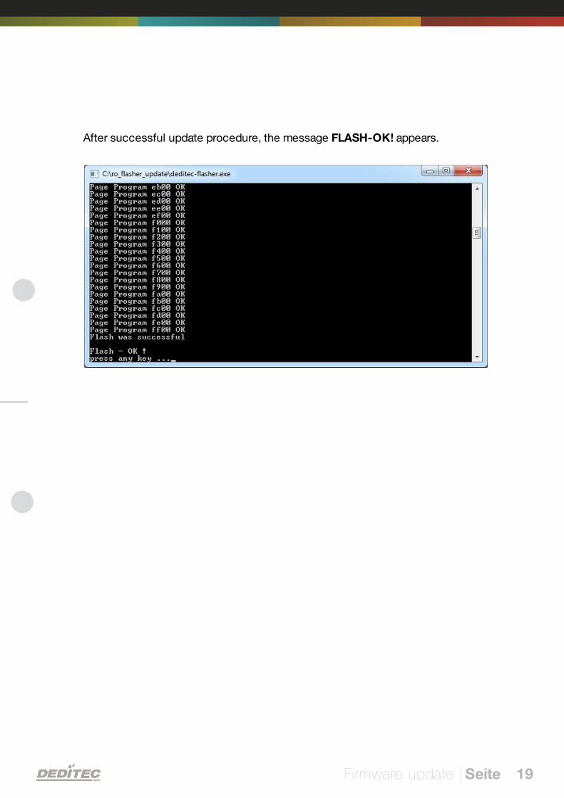
After successful update procedure, the message FLASH-OK! appears.
IV
Software | Seite 20
Software
Software | Seite 21
4. Software
4.1. Using our products
4.1.1. Access via graphical applications
We provide driverinterfaces e.g. for LabVIEW and ProfiLab. The DELIB driverlibrary is the basis, which can be directly activated by ProfiLAB.
For LabVIEW, we provide a simple driver connection with examples!
4.1.2. Access via the DELIB driver library
In the appendix, you can find the complete function reference for the integrationof our API-functions in your software. In addition we provide examples for thefollowing programming languages:
C
C++
C#
Delphi
VisualBasic
VB.NET
MS-Office
4.1.3. Access via protocol
The protocol for the activation of our products is open source. So you are ableto use our products on systems without Windows or Linux.
Software | Seite 22
4.1.4. Access via provided test programs
We provide simple handling test programs for the most important functions ofour products. These will be installed automatically by the installation of theDELIB driver library.
So you can test directly e.g. relays or you can check the voltage of an A/Dconverter.
Software | Seite 23
4.2. DELIB driver library
4.2.1. Overview
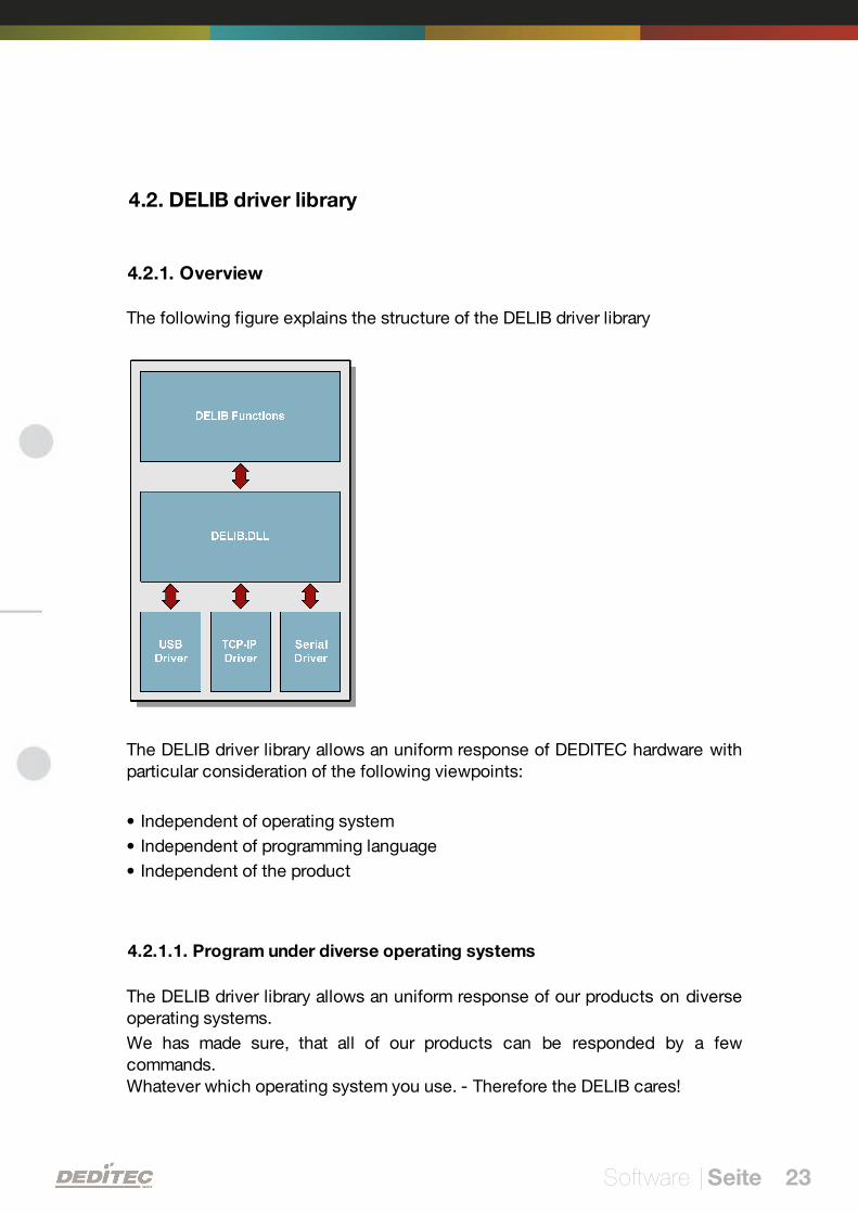
The following figure explains the structure of the DELIB driver library
The DELIB driver library allows an uniform response of DEDITEC hardware withparticular consideration of the following viewpoints:
Independent of operating system
Independent of programming language
Independent of the product
4.2.1.1. Program under diverse operating systems
The DELIB driver library allows an uniform response of our products on diverseoperating systems.
We has made sure, that all of our products can be responded by a fewcommands.Whatever which operating system you use. - Therefore the DELIB cares!
Software | Seite 24
4.2.1.2. Program with diverse programming languages
We provide uniform commands to create own applications. This will be solvedby the DELIB driver library.
You choose the programming language!
It can be simply developed applications under C++, C, Visual Basic, Delphi orLabVIEW®.
4.2.1.3. Program independent of the interface
Write your application independent of the interface !
Program an application for an USB product of us. - Also, it will work with anethernet or RS-232 product of us !
4.2.1.4. SDK-Kit for Programmer
Integrate the DELIB in your application. On demand you receive an installationscript for free, which allows you, to integrate the DELIB installation in yourapplication.
Software | Seite 25
4.2.2. Supported operating systems
Our products support the following operating systems:
Windows 7
Windows Vista
Windows XP
Windows 2000
Linux
4.2.3. Supported programming languages
Our products are responsive via the following programming languages:
C
C++
C#
Delphi
VisualBasic
VB.NET
MS-Office
Software | Seite 26
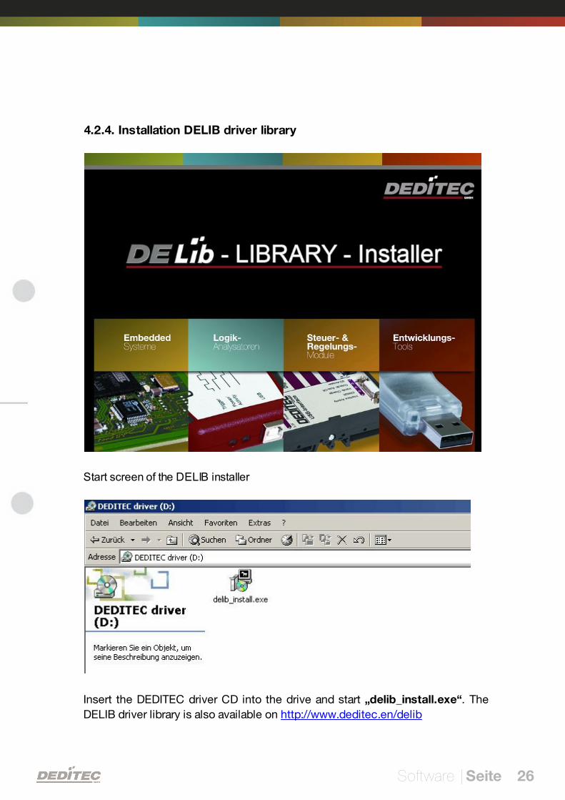
4.2.4. Installation DELIB driver library
Start screen of the DELIB installer
Insert the DEDITEC driver CD into the drive and start „delib_install.exe“. The
DELIB driver library is also available on http://www.deditec.en/delib
Software | Seite 27
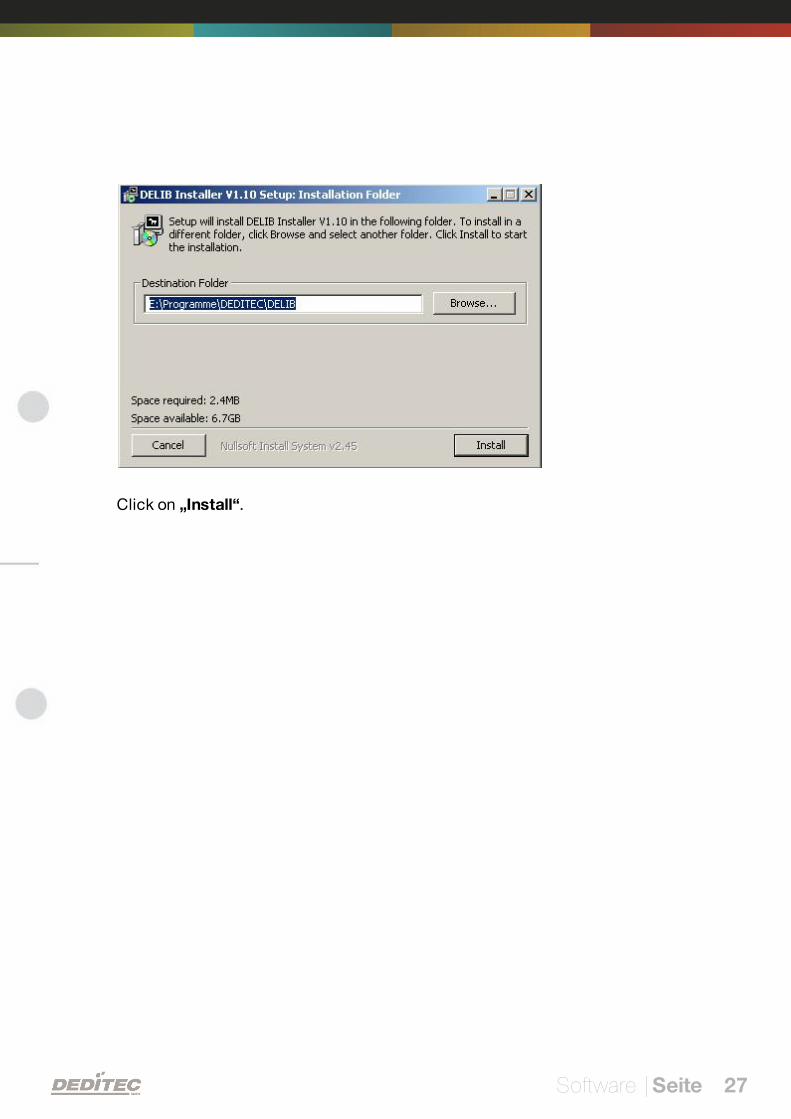
Click on „Install“.
Software | Seite 28
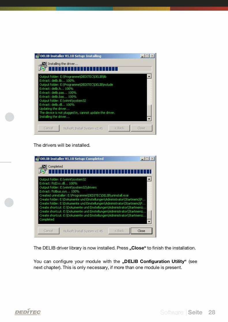
The drivers will be installed.
The DELIB driver library is now installed. Press „Close“ to finish the installation.
You can configure your module with the „DELIB Configuration Utility“ (see
next chapter). This is only necessary, if more than one module is present.
Software | Seite 29
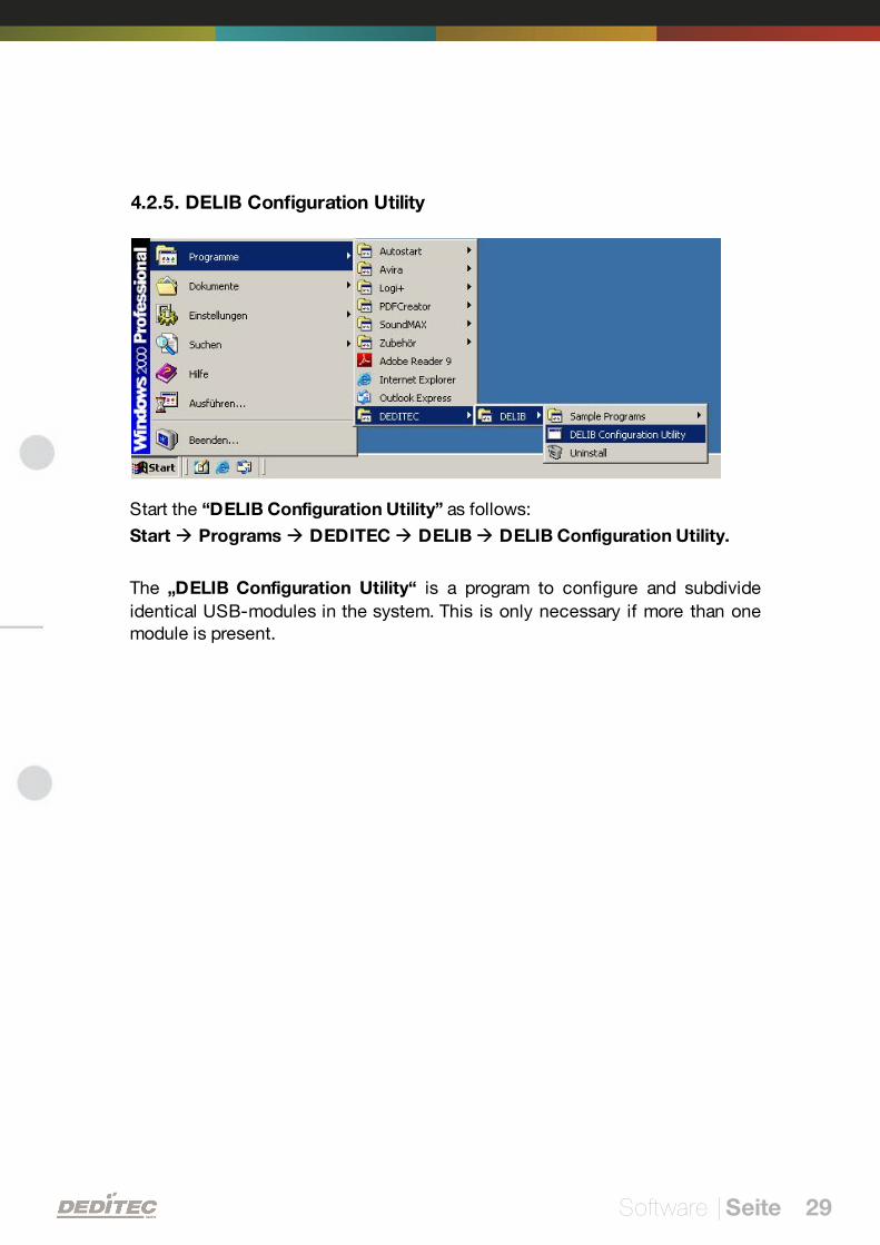
4.2.5. DELIB Configuration Utility
Start the “DELIB Configuration Utility” as follows:
Start Programs DEDITEC DELIB DELIB Configuration Utility.
The „DELIB Configuration Utility“ is a program to configure and subdivide
identical USB-modules in the system. This is only necessary if more than onemodule is present.
Software | Seite 30
4.3. Integration of the DELIB
4.3.1. Integration of the delib.h in Visual-C/C++
Description of the DELIB integration in Visual-C/C++
The DELIB Installation defines environment variables to facilitate links to theDELIB-include and DELIB-lib directory.
DELIB_LIB = C:\Programs\DEDITEC\DELIB\lib
DELIB_INCLUDE = C:\Programs\DEDITEC\DELIB\include
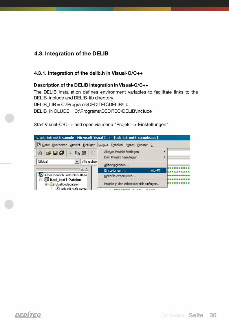
Start Visual-C/C++ and open via menu "Projekt -> Einstellungen"
Software | Seite 31
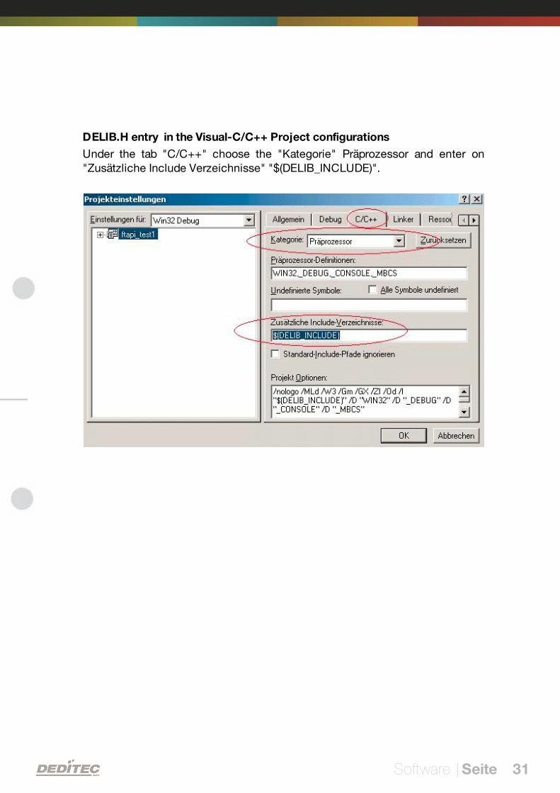
DELIB.H entry in the Visual-C/C++ Project configurations
Under the tab "C/C++" choose the "Kategorie" Präprozessor and enter on"Zusätzliche Include Verzeichnisse" "$(DELIB_INCLUDE)".
Software | Seite 32
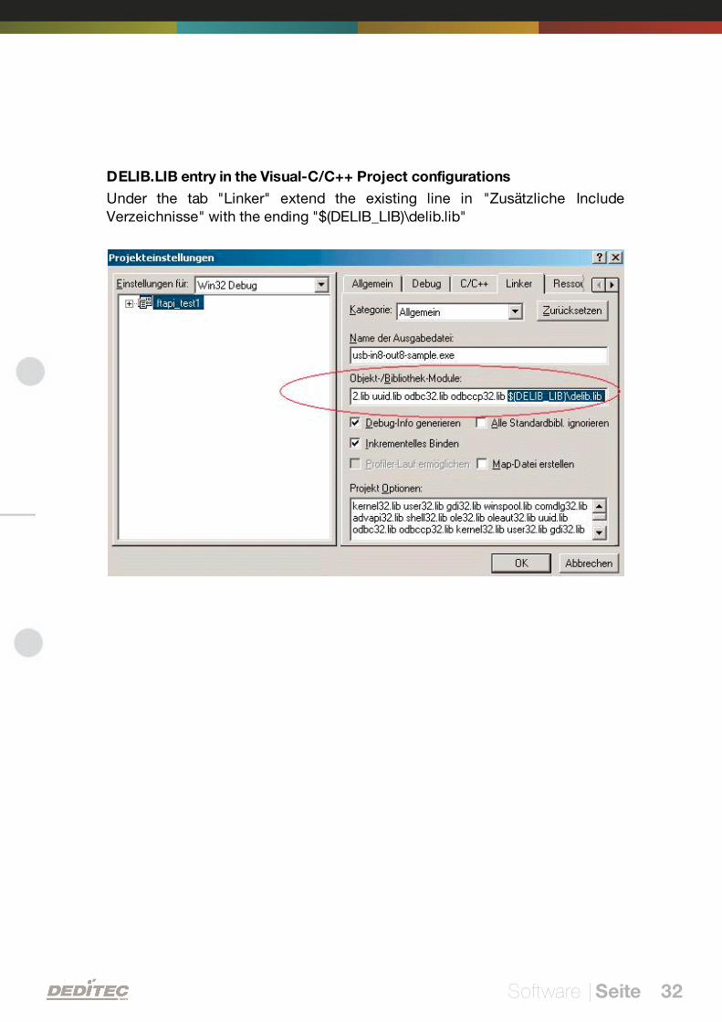
DELIB.LIB entry in the Visual-C/C++ Project configurations
Under the tab "Linker" extend the existing line in "Zusätzliche IncludeVerzeichnisse" with the ending "$(DELIB_LIB)\delib.lib"
Software | Seite 33
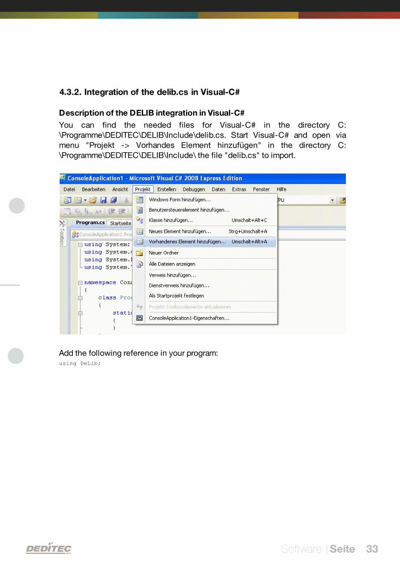
4.3.2. Integration of the delib.cs in Visual-C#
Description of the DELIB integration in Visual-C#
You can find the needed files for Visual-C# in the directory C:\Programme\DEDITEC\DELIB\Include\delib.cs. Start Visual-C# and open viamenu "Projekt -> Vorhandes Element hinzufügen" in the directory C:\Programme\DEDITEC\DELIB\Include\ the file "delib.cs" to import.
Add the following reference in your program:using DeLib;
Software | Seite 34
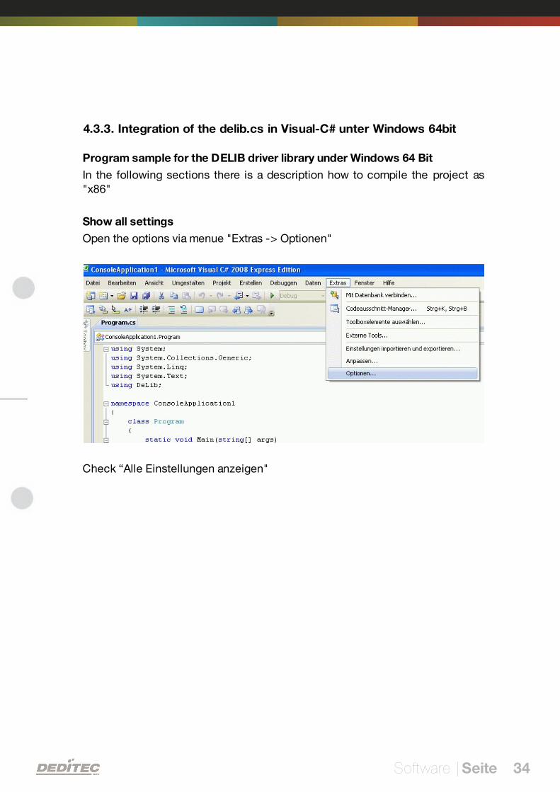
4.3.3. Integration of the delib.cs in Visual-C# unter Windows 64bit
Program sample for the DELIB driver library under Windows 64 Bit
In the following sections there is a description how to compile the project as"x86"
Show all settings
Open the options via menue "Extras -> Optionen"
Check “Alle Einstellungen anzeigen"
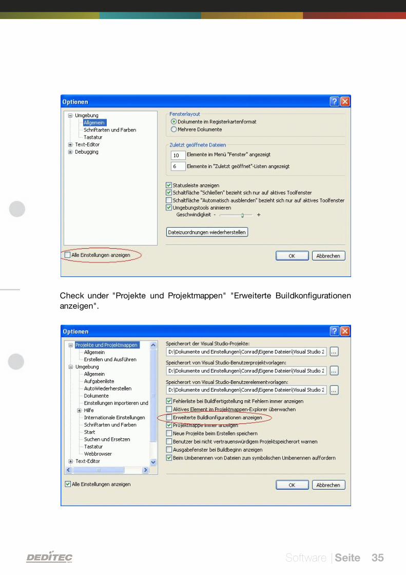
Software | Seite 35
Check under "Projekte und Projektmappen" "Erweiterte Buildkonfigurationenanzeigen".
Software | Seite 36
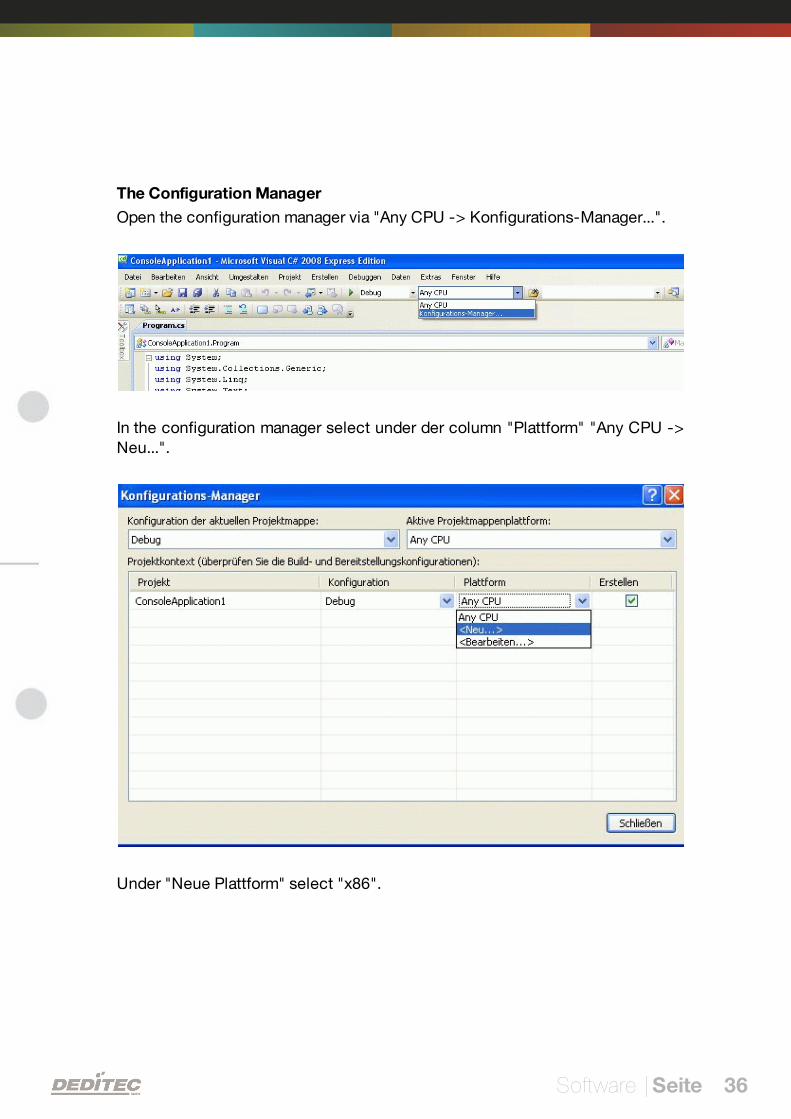
The Configuration Manager
Open the configuration manager via "Any CPU -> Konfigurations-Manager...".
In the configuration manager select under der column "Plattform" "Any CPU ->Neu...".
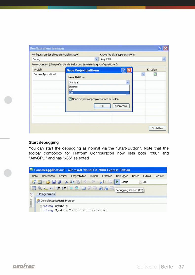
Under "Neue Plattform" select "x86".
Software | Seite 37
Start debugging
You can start the debugging as normal via the "Start-Button". Note that thetoolbar combobox for Platform Configuration now lists both "x86" and"AnyCPU" and has "x86" selected
Software | Seite 38
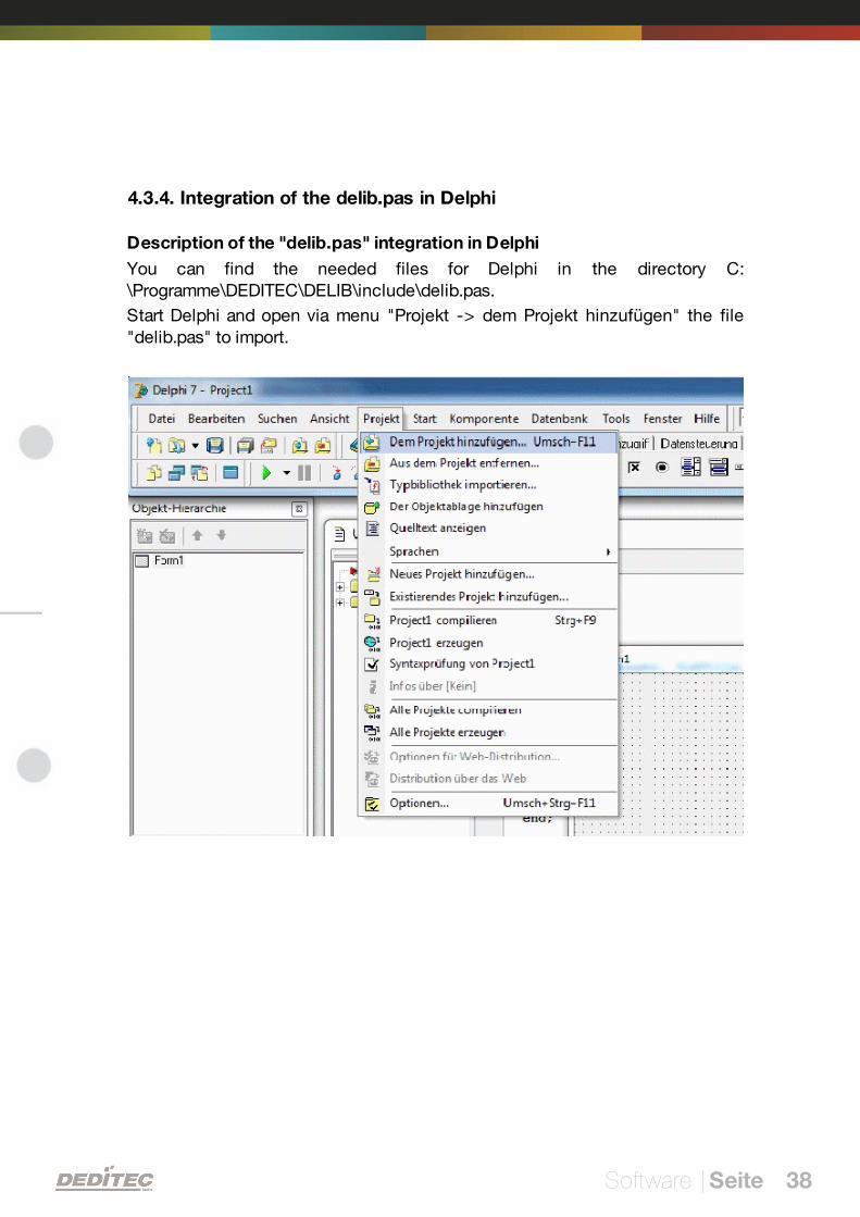
4.3.4. Integration of the delib.pas in Delphi
Description of the "delib.pas" integration in Delphi
You can find the needed files for Delphi in the directory C:\Programme\DEDITEC\DELIB\include\delib.pas.
Start Delphi and open via menu "Projekt -> dem Projekt hinzufügen" the file"delib.pas" to import.
Software | Seite 39
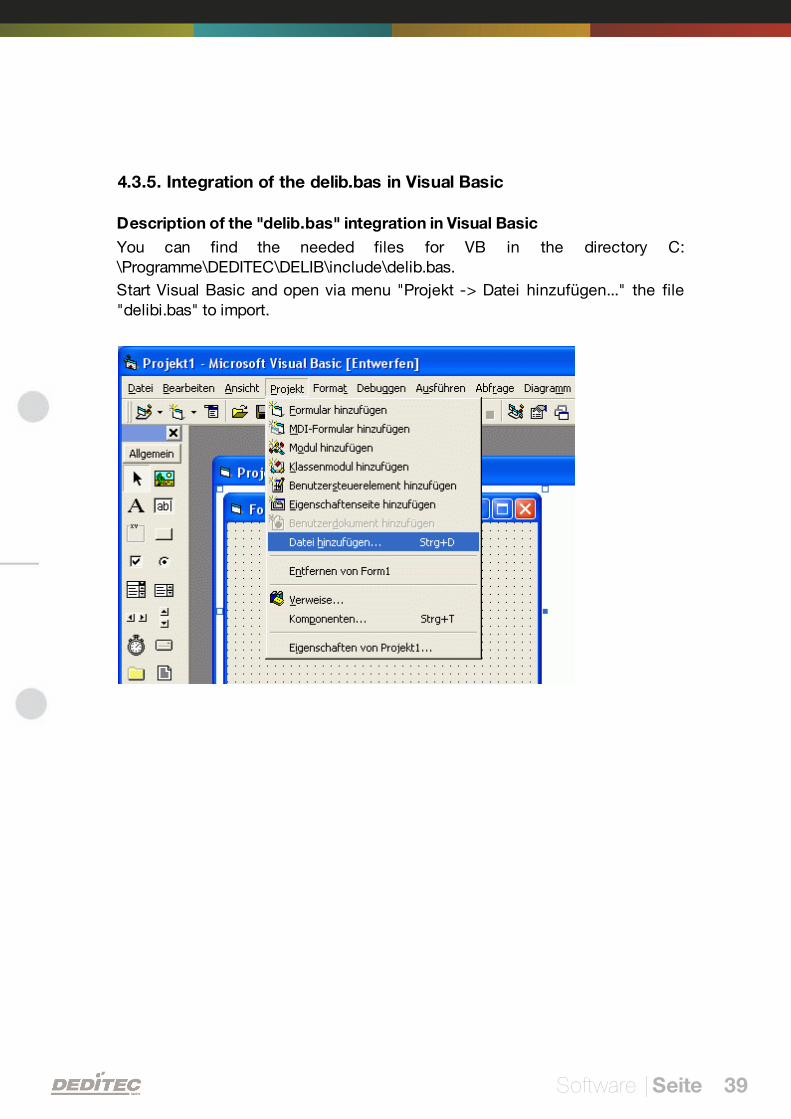
4.3.5. Integration of the delib.bas in Visual Basic
Description of the "delib.bas" integration in Visual Basic
You can find the needed files for VB in the directory C:\Programme\DEDITEC\DELIB\include\delib.bas.
Start Visual Basic and open via menu "Projekt -> Datei hinzufügen..." the file"delibi.bas" to import.
Software | Seite 40
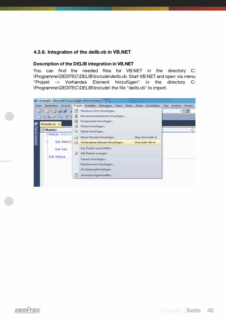
4.3.6. Integration of the delib.vb in VB.NET
Description of the DELIB integration in VB.NET
You can find the needed files for VB.NET in the directory C:\Programme\DEDITEC\DELIB\Include\delib.vb. Start VB.NET and open via menu"Projekt -> Vorhandes Element hinzufügen" in the directory C:\Programme\DEDITEC\DELIB\Include\ the file "delib.vb" to import.
Software | Seite 41
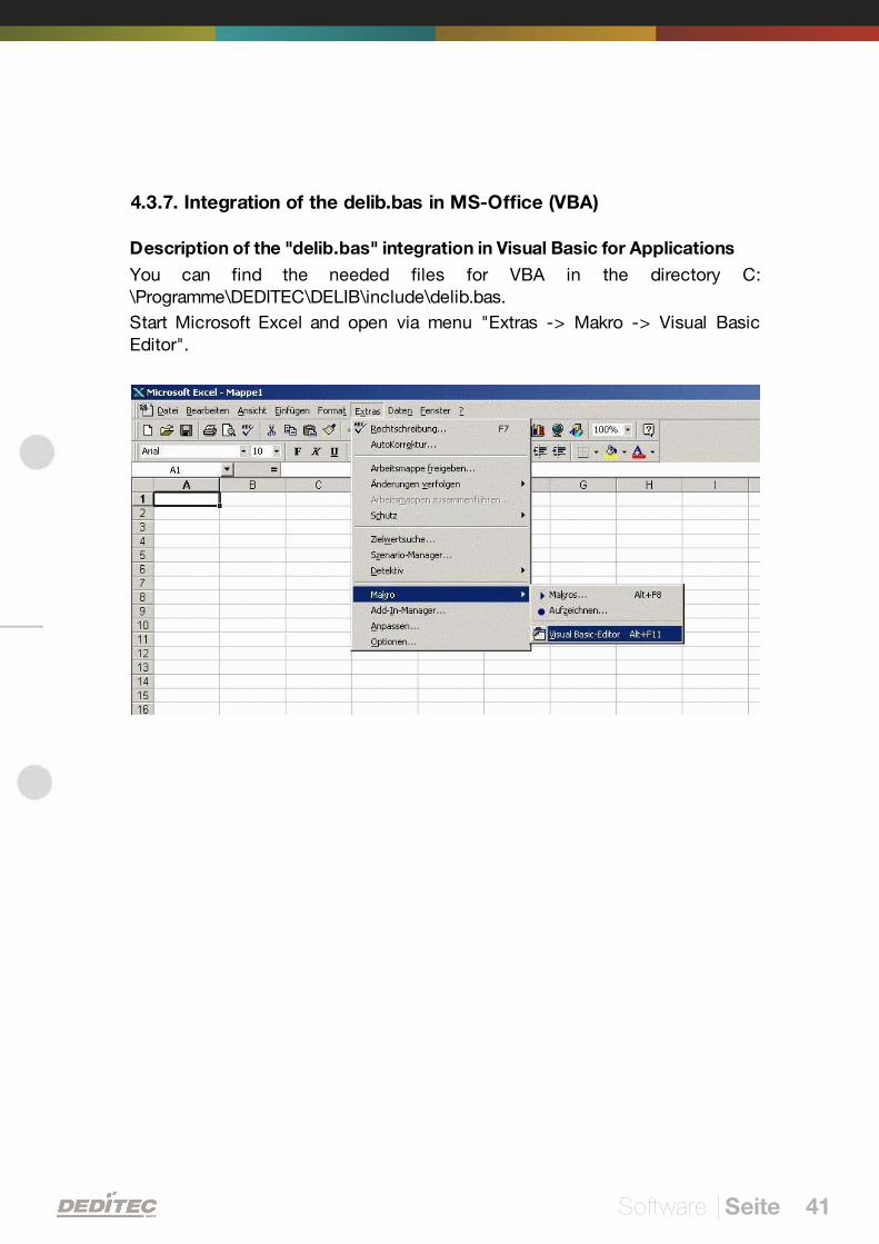
4.3.7. Integration of the delib.bas in MS-Office (VBA)
Description of the "delib.bas" integration in Visual Basic for Applications
You can find the needed files for VBA in the directory C:\Programme\DEDITEC\DELIB\include\delib.bas.
Start Microsoft Excel and open via menu "Extras -> Makro -> Visual BasicEditor".
Software | Seite 42
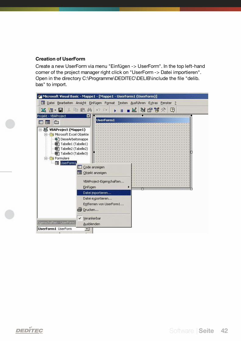
Creation of UserForm
Create a new UserForm via menu "Einfügen -> UserForm". In the top left-handcorner of the project manager right click on "UserForm -> Datei importieren".Open in the directory C:\Programme\DEDITEC\DELIB\include the file "delib.bas" to import.
Software | Seite 43
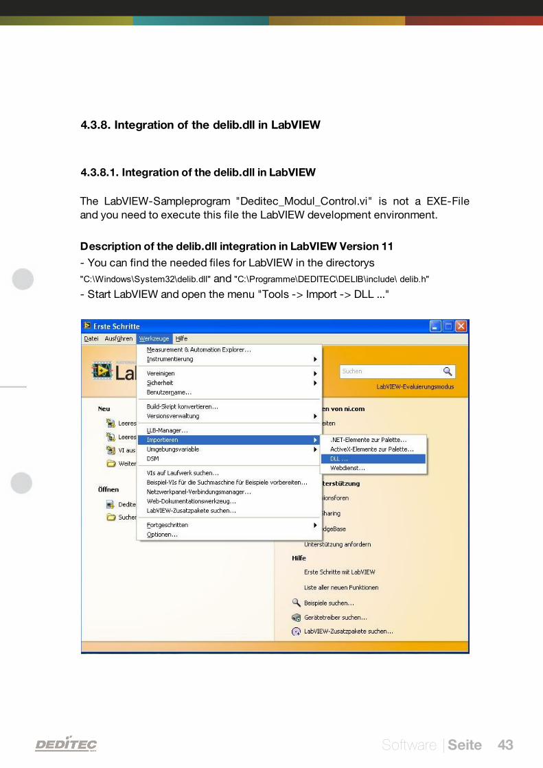
4.3.8. Integration of the delib.dll in LabVIEW
4.3.8.1. Integration of the delib.dll in LabVIEW
The LabVIEW-Sampleprogram "Deditec_Modul_Control.vi" is not a EXE-Fileand you need to execute this file the LabVIEW development environment.
Description of the delib.dll integration in LabVIEW Version 11
- You can find the needed files for LabVIEW in the directorys
"C:\Windows\System32\delib.dll" and "C:\Programme\DEDITEC\DELIB\include\ delib.h"
- Start LabVIEW and open the menu "Tools -> Import -> DLL ..."
Software | Seite 44
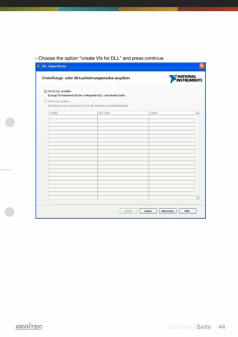
- Choose the option "create VIs for DLL" and press continue
Software | Seite 45
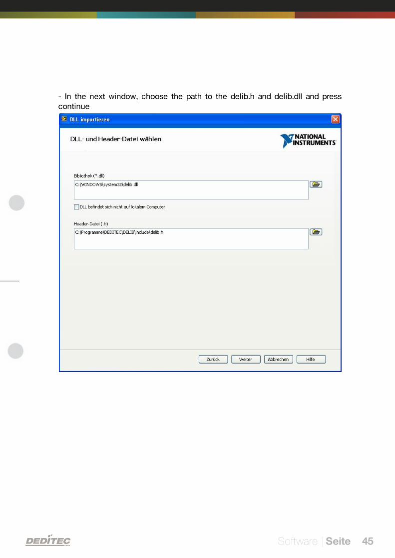
- In the next window, choose the path to the delib.h and delib.dll and presscontinue
Software | Seite 46
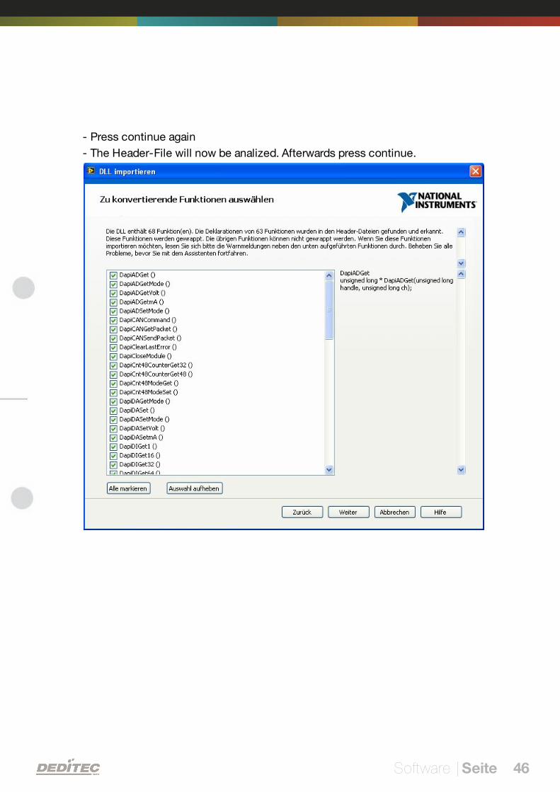
- Press continue again
- The Header-File will now be analized. Afterwards press continue.
Software | Seite 47
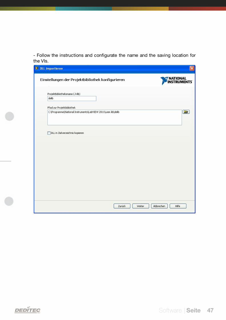
- Follow the instructions and configurate the name and the saving location forthe VIs.

Software | Seite 48
- In the new window choose "Easy error correction" in the drop-down menu andpress continue.
Software | Seite 49
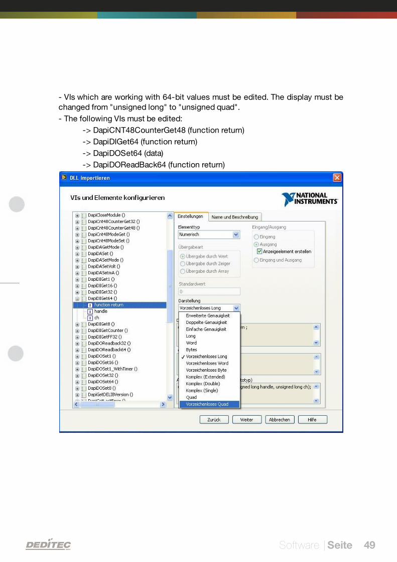
- VIs which are working with 64-bit values must be edited. The display must bechanged from "unsigned long" to "unsigned quad".
- The following VIs must be edited:
-> DapiCNT48CounterGet48 (function return)
-> DapiDIGet64 (function return)
-> DapiDOSet64 (data)
-> DapiDOReadBack64 (function return)
Software | Seite 50
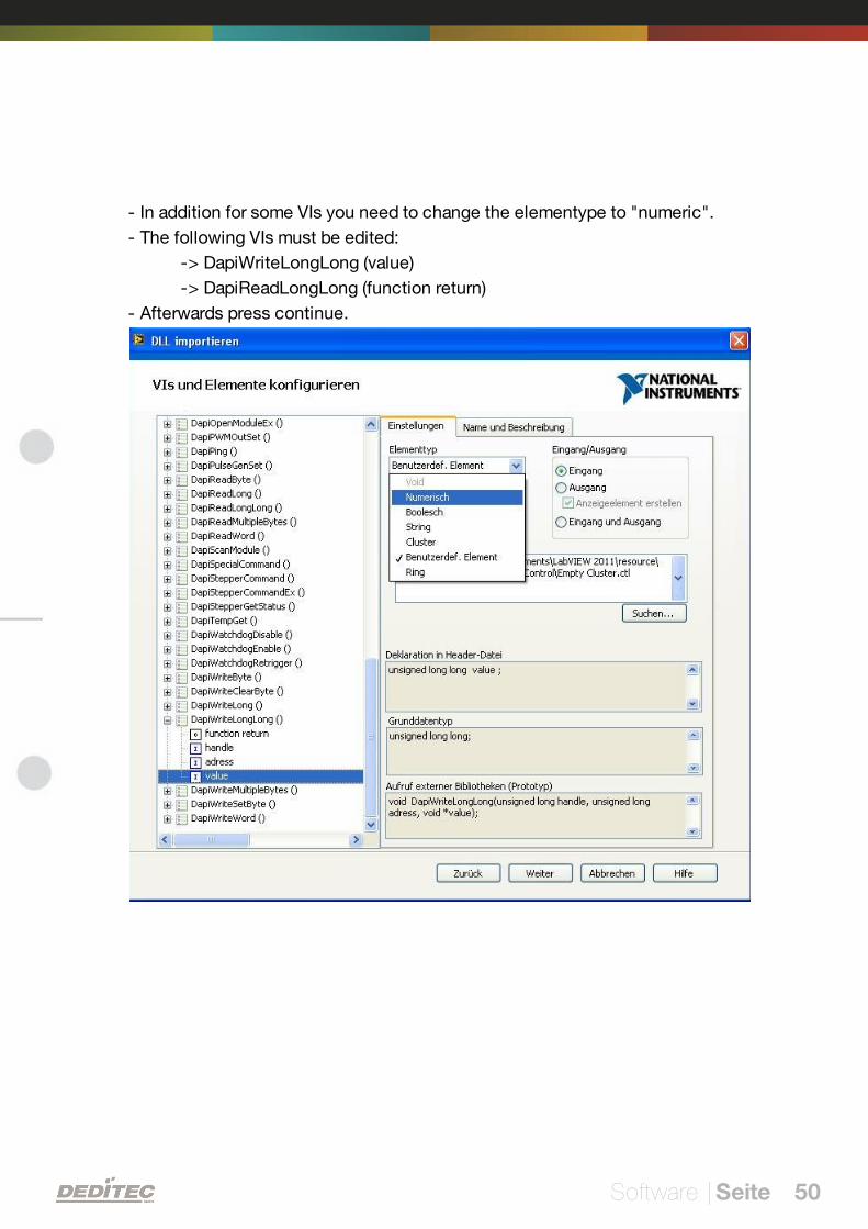
- In addition for some VIs you need to change the elementype to "numeric".
- The following VIs must be edited:
-> DapiWriteLongLong (value)
-> DapiReadLongLong (function return)
- Afterwards press continue.
Software | Seite 51
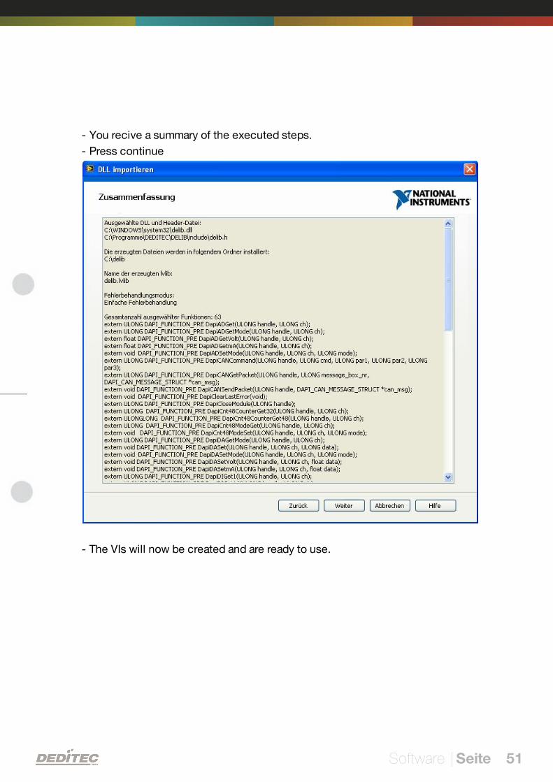
- You recive a summary of the executed steps.
- Press continue
- The VIs will now be created and are ready to use.
Software | Seite 52
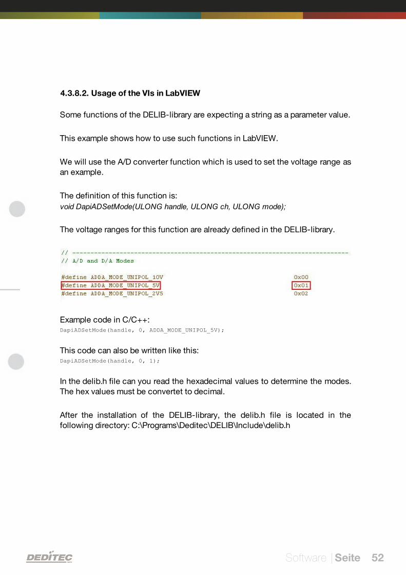
4.3.8.2. Usage of the VIs in LabVIEW
Some functions of the DELIB-library are expecting a string as a parameter value.
This example shows how to use such functions in LabVIEW.
We will use the A/D converter function which is used to set the voltage range asan example.
The definition of this function is:
void DapiADSetMode(ULONG handle, ULONG ch, ULONG mode);
The voltage ranges for this function are already defined in the DELIB-library.
Example code in C/C++:DapiADSetMode(handle, 0, ADDA_MODE_UNIPOL_5V);
This code can also be written like this:DapiADSetMode(handle, 0, 1);
In the delib.h file can you read the hexadecimal values to determine the modes.The hex values must be convertet to decimal.
After the installation of the DELIB-library, the delib.h file is located in thefollowing directory: C:\Programs\Deditec\DELIB\Include\delib.h
Software | Seite 53
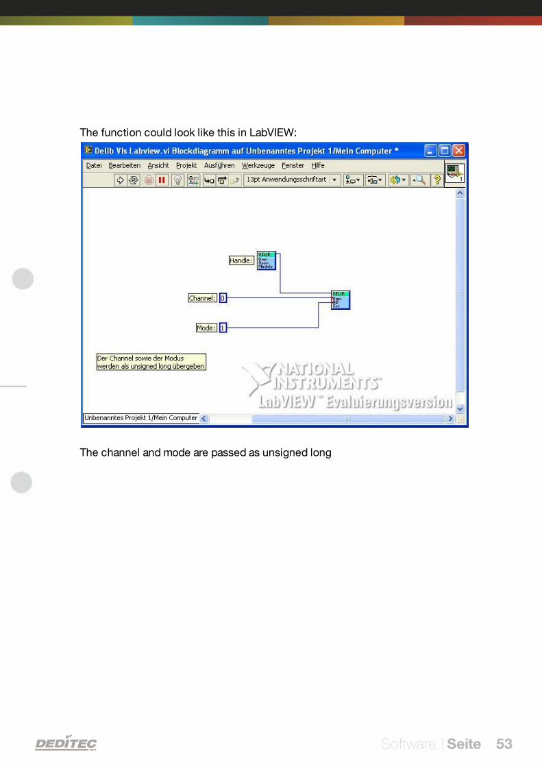
The function could look like this in LabVIEW:
The channel and mode are passed as unsigned long
Software | Seite 54
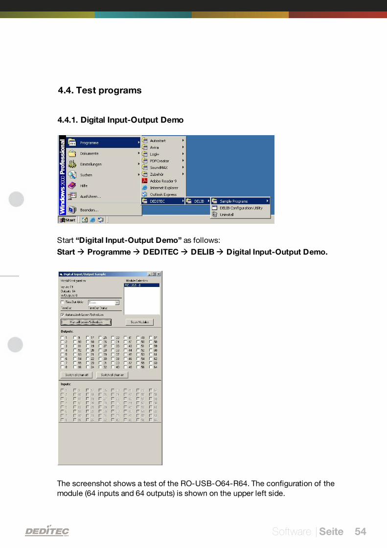
4.4. Test programs
4.4.1. Digital Input-Output Demo
Start “Digital Input-Output Demo” as follows:
Start Programme DEDITEC DELIB Digital Input-Output Demo.
The screenshot shows a test of the RO-USB-O64-R64. The configuration of themodule (64 inputs and 64 outputs) is shown on the upper left side.
Software | Seite 55
4.5. DELIB CLI (command-line interface)
In some programming languages (like PHP), you can't include DLLs, therefore isan extra console command, which you can directly call out of the program (withappropriate parameters). You can find this command after installation of theDELIB driverlibrary in the directory C:\Programme\DEDITEC\DELIB\Programs\Console.
You can find the DELIB CLI Command for Windows after Installation of theDELIB driverlibrary in the directory C:\Programme\DEDITEC\DELIB\programs\cli\.
The DELIB CLI Command for Linux is located in the directory "/deditec-cli/,after unzipping the ZIP-Archiv "delib-linux-cli".
Definition (Windows)
delib_cli command channel [value | unit ["nounit"] ]
Definition for USB-Module (Linux)
sudo delib-cli-usb command channel [value | unit ["nounit"] ]
Definition for RO-ETH-Module (Linux)
delib-cli-eth command channel [value | unit ["nounit"] ]
Note: The parameters are separated by spaces.
These commands and parameters are not case sensitive.
Parameter
command channel value unit nounit
di1 0, 1, 2, ...
- hexnouni
t
di8
0, 8, 16, ...di16
di24
do1 0, 1, 2, ... 0/1 (1-bit command)
- -do8
0, 8, 16, ...
8-bit value(Bit 0 for channel 1, Bit
1 for channel 2, ...)do16 16-bit value
do24 24-bit value
ai 0, 1, 2, ... - hex, volt, mA nouni
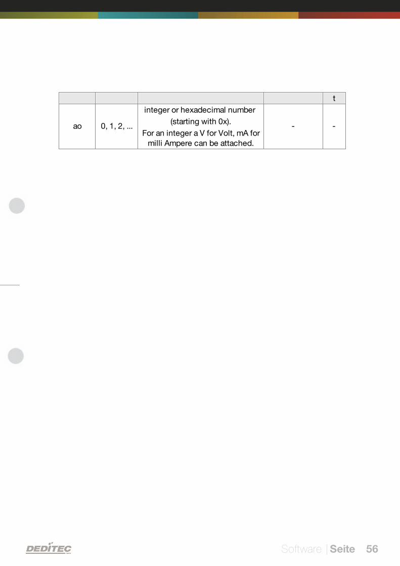
Software | Seite 56
t
ao 0, 1, 2, ...
integer or hexadecimal number
(starting with 0x).
For an integer a V for Volt, mA formilli Ampere can be attached.
- -
Software | Seite 57
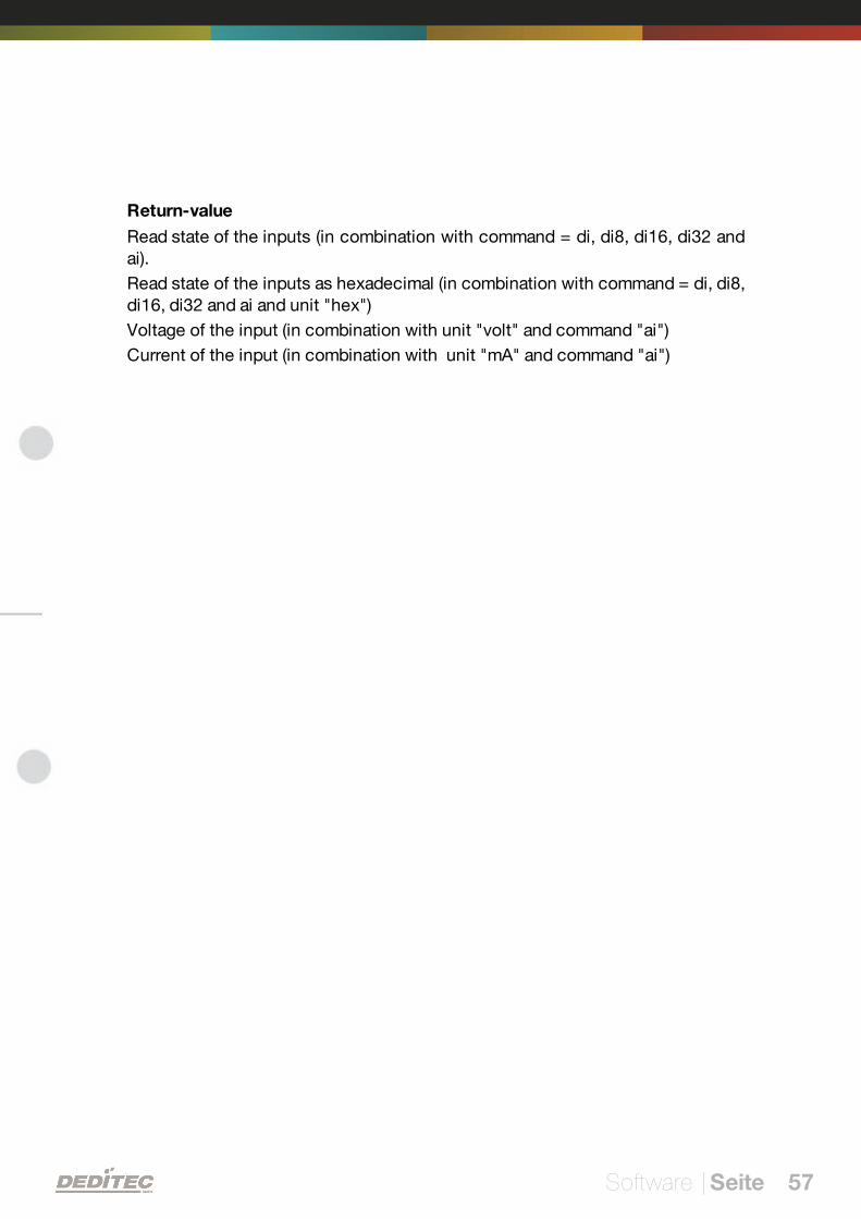
Return-value
Read state of the inputs (in combination with command = di, di8, di16, di32 andai).
Read state of the inputs as hexadecimal (in combination with command = di, di8,di16, di32 and ai and unit "hex")
Voltage of the input (in combination with unit "volt" and command "ai")
Current of the input (in combination with unit "mA" and command "ai")
Software | Seite 58
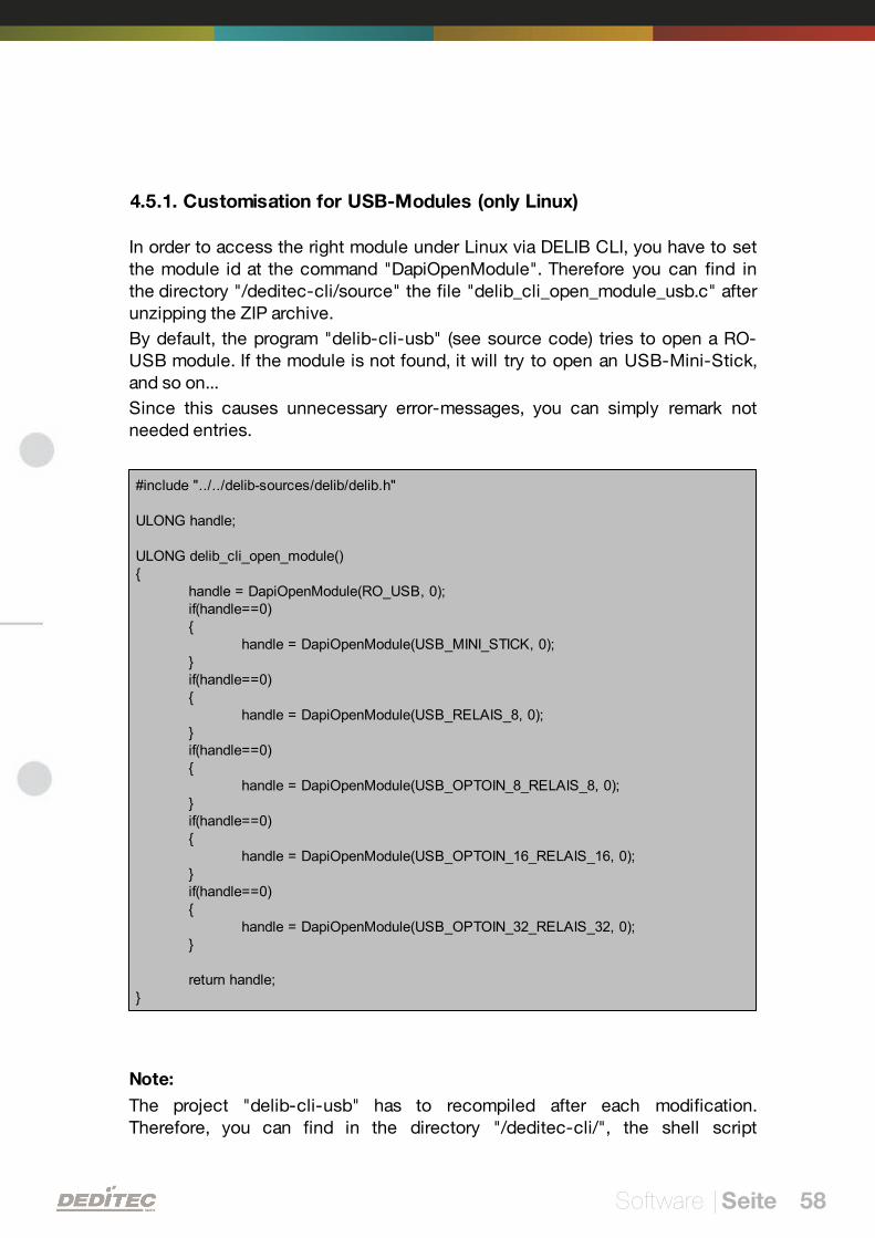
4.5.1. Customisation for USB-Modules (only Linux)
In order to access the right module under Linux via DELIB CLI, you have to setthe module id at the command "DapiOpenModule". Therefore you can find inthe directory "/deditec-cli/source" the file "delib_cli_open_module_usb.c" afterunzipping the ZIP archive.
By default, the program "delib-cli-usb" (see source code) tries to open a RO-USB module. If the module is not found, it will try to open an USB-Mini-Stick,and so on...
Since this causes unnecessary error-messages, you can simply remark notneeded entries.
#include "../../delib-sources/delib/delib.h"
ULONG handle;
ULONG delib_cli_open_module(){
handle = DapiOpenModule(RO_USB, 0);if(handle==0){
handle = DapiOpenModule(USB_MINI_STICK, 0);}if(handle==0){
handle = DapiOpenModule(USB_RELAIS_8, 0);}if(handle==0){
handle = DapiOpenModule(USB_OPTOIN_8_RELAIS_8, 0);}if(handle==0){
handle = DapiOpenModule(USB_OPTOIN_16_RELAIS_16, 0);}if(handle==0){
handle = DapiOpenModule(USB_OPTOIN_32_RELAIS_32, 0);}
return handle;}
Note:
The project "delib-cli-usb" has to recompiled after each modification.Therefore, you can find in the directory "/deditec-cli/", the shell script
Software | Seite 59
"compile_delib_cli_usb.sh", with which you can compile the project underLinux.
Software | Seite 60
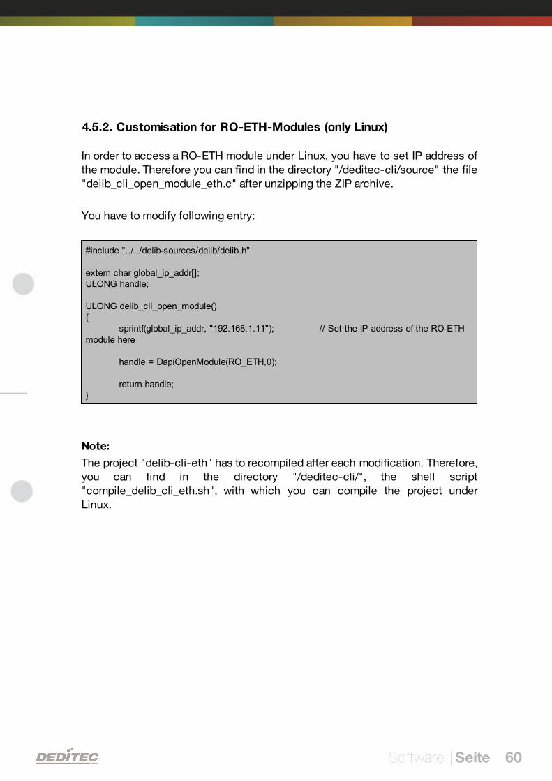
4.5.2. Customisation for RO-ETH-Modules (only Linux)
In order to access a RO-ETH module under Linux, you have to set IP address ofthe module. Therefore you can find in the directory "/deditec-cli/source" the file"delib_cli_open_module_eth.c" after unzipping the ZIP archive.
You have to modify following entry:
#include "../../delib-sources/delib/delib.h"
extern char global_ip_addr[];ULONG handle;
ULONG delib_cli_open_module(){
sprintf(global_ip_addr, "192.168.1.11"); // Set the IP address of the RO-ETHmodule here
handle = DapiOpenModule(RO_ETH,0);
return handle;}
Note:
The project "delib-cli-eth" has to recompiled after each modification. Therefore,you can find in the directory "/deditec-cli/", the shell script"compile_delib_cli_eth.sh", with which you can compile the project underLinux.
Software | Seite 61
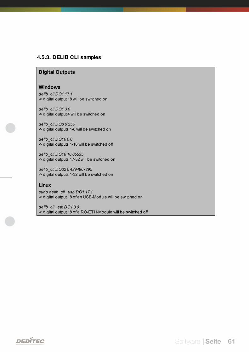
4.5.3. DELIB CLI samples
Digital Outputs
Windows
delib_cli DO1 17 1-> digital output 18 will be switched on
delib_cli DO1 3 0-> digital output 4 will be switched on
delib_cli DO8 0 255-> digital outputs 1-8 will be switched on
delib_cli DO16 0 0-> digital outputs 1-16 will be switched off
delib_cli DO16 16 65535-> digital outputs 17-32 will be switched on
delib_cli DO32 0 4294967295-> digital outputs 1-32 will be switched on
Linux
sudo delib_cli _usb DO1 17 1-> digital output 18 of an USB-Module will be switched on
delib_cli _eth DO1 3 0-> digital output 18 of a RO-ETH-Module will be switched off
Software | Seite 62
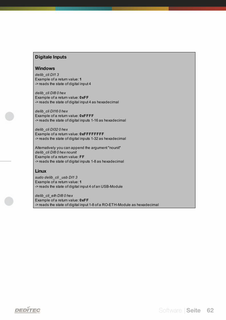
Digitale Inputs
Windows
delib_cli DI1 3Example of a return value: 1 -> reads the state of digital input 4
delib_cli DI8 0 hexExample of a return value: 0xFF-> reads the state of digital input 4 as hexadecimal
delib_cli DI16 0 hexExample of a return value: 0xFFFF-> reads the state of digital inputs 1-16 as hexadecimal
delib_cli DI32 0 hexExample of a return value: 0xFFFFFFFF-> reads the state of digital inputs 1-32 as hexadecimal
Alternatively you can append the argument "nounit"delib_cli DI8 0 hex nounitExample of a return value: FF-> reads the state of digital inputs 1-8 as hexadecimal
Linux
sudo delib_cli _usb DI1 3Example of a return value: 1-> reads the state of digital input 4 of an USB-Module
delib_cli_eth DI8 0 hexExample of a return value: 0xFF-> reads the state of digital input 1-8 of a RO-ETH-Module as hexadecimal
Software | Seite 63
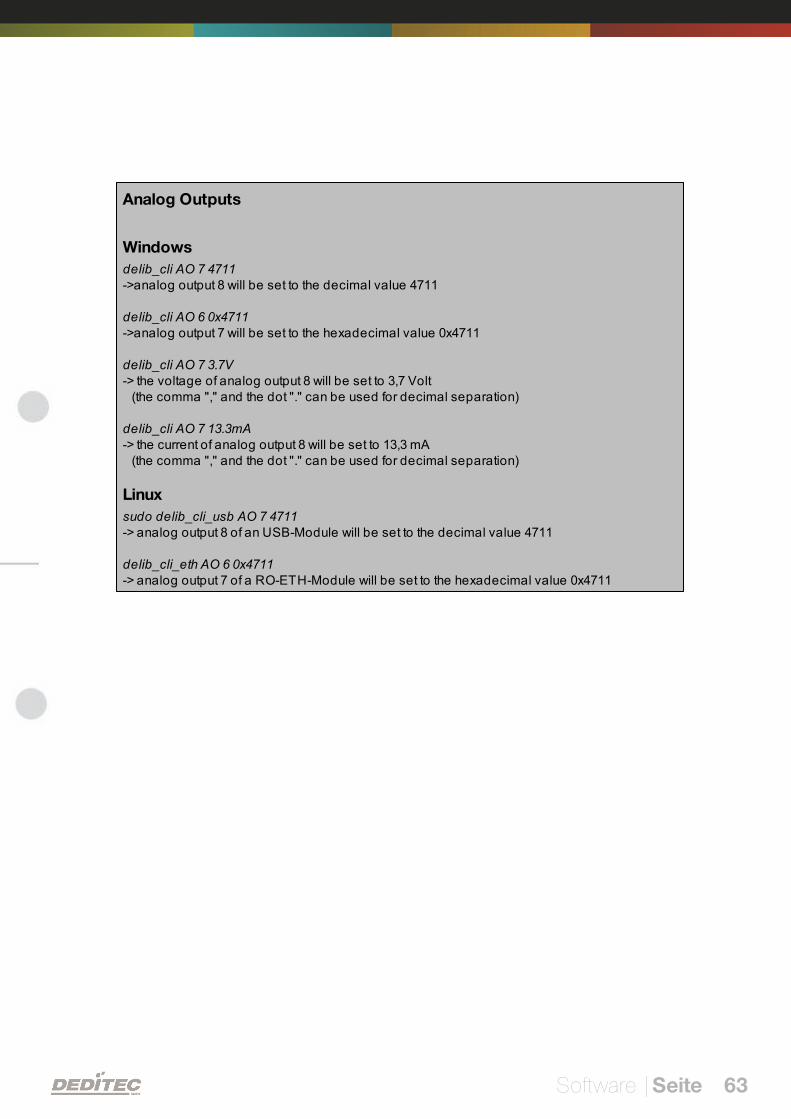
Analog Outputs
Windows
delib_cli AO 7 4711->analog output 8 will be set to the decimal value 4711
delib_cli AO 6 0x4711->analog output 7 will be set to the hexadecimal value 0x4711
delib_cli AO 7 3.7V-> the voltage of analog output 8 will be set to 3,7 Volt (the comma "," and the dot "." can be used for decimal separation)
delib_cli AO 7 13.3mA-> the current of analog output 8 will be set to 13,3 mA (the comma "," and the dot "." can be used for decimal separation)
Linux
sudo delib_cli_usb AO 7 4711-> analog output 8 of an USB-Module will be set to the decimal value 4711
delib_cli_eth AO 6 0x4711-> analog output 7 of a RO-ETH-Module will be set to the hexadecimal value 0x4711
Software | Seite 64
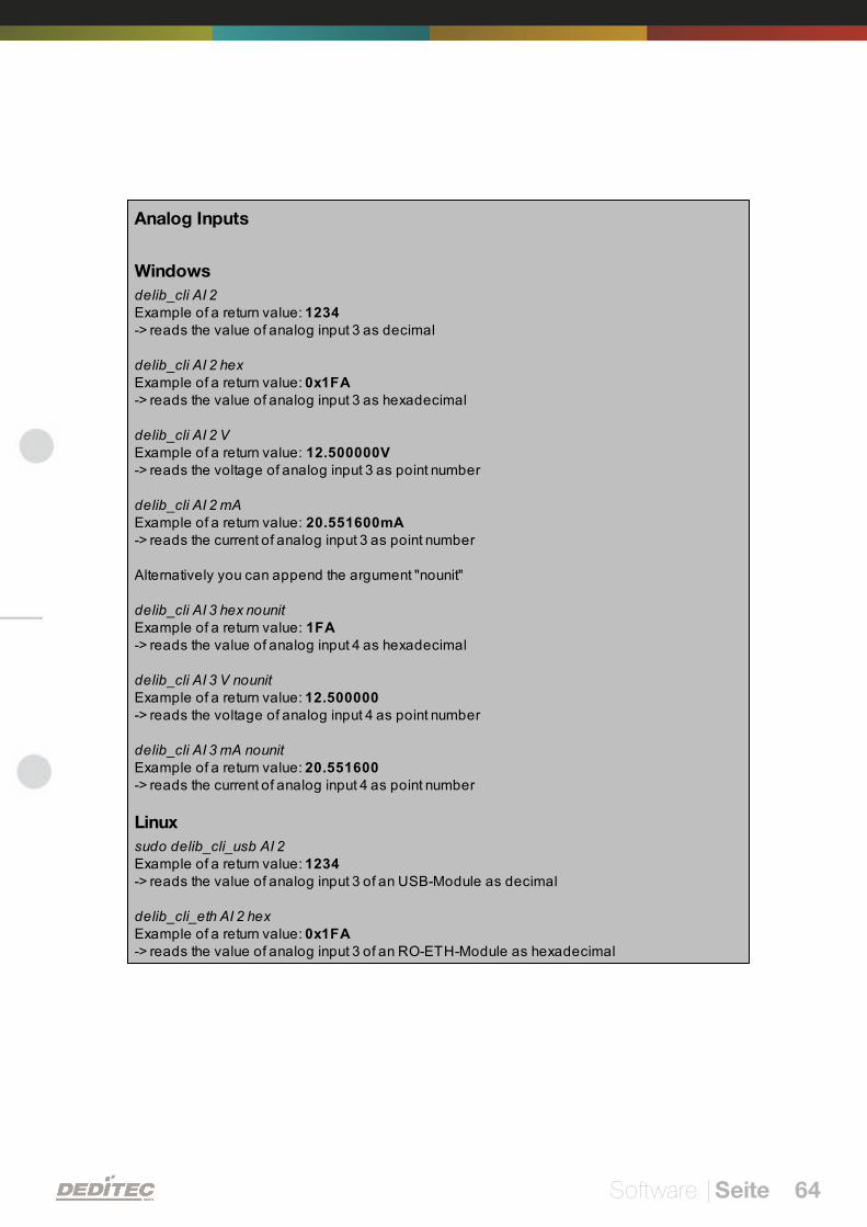
Analog Inputs
Windows
delib_cli AI 2Example of a return value: 1234-> reads the value of analog input 3 as decimal
delib_cli AI 2 hexExample of a return value: 0x1FA-> reads the value of analog input 3 as hexadecimal
delib_cli AI 2 VExample of a return value: 12.500000V-> reads the voltage of analog input 3 as point number
delib_cli AI 2 mAExample of a return value: 20.551600mA-> reads the current of analog input 3 as point number
Alternatively you can append the argument "nounit"
delib_cli AI 3 hex nounitExample of a return value: 1FA-> reads the value of analog input 4 as hexadecimal
delib_cli AI 3 V nounitExample of a return value: 12.500000-> reads the voltage of analog input 4 as point number
delib_cli AI 3 mA nounitExample of a return value: 20.551600-> reads the current of analog input 4 as point number
Linux
sudo delib_cli_usb AI 2Example of a return value: 1234-> reads the value of analog input 3 of an USB-Module as decimal
delib_cli_eth AI 2 hexExample of a return value: 0x1FA-> reads the value of analog input 3 of an RO-ETH-Module as hexadecimal

V
DELIB API reference | Seite 65
DELIB API reference
DELIB API reference | Seite 66
5. DELIB API reference
5.1. Management functions
5.1.1. DapiOpenModule
Description
This function opens a particular module.
Definition
ULONG DapiOpenModule(ULONG moduleID, ULONG nr);
Parameters
moduleID=Specifies the module, which is to be opened (see delib.h)
nr=Indicates No of module which is to be opened.
nr=0 -> 1. module
nr=1 -> 2. module
Return value
handle=handle to the corresponding module
handle=0 -> Module was not found
Remarks
The handle returned by this function is needed to identify the module for allother functions.
Example program
// USB-Modul öffnenhandle = DapiOpenModule(RO_USB1, 0);printf("handle = %x\n", handle);if (handle==0){// USB Modul wurde nicht gefundenprintf("Modul konnte nicht geöffnet werden\n");return;}
DELIB API reference | Seite 67
5.1.2. DapiCloseModule
Description
This command closes an opened module.
Definition
ULONG DapiCloseModule(ULONG handle);
Parameters
handle=This is the handle of an opened module
Return value
none
Example program
// Close the moduleDapiCloseModule(handle);
DELIB API reference | Seite 68
5.1.3. DapiGetDELIBVersion
Description
This function returns the installed DELIB version.
Definition
ULONG DapiGetDELIBVersion(ULONG mode, ULONG par);
Parameters
mode=Mode, with which the version is readout (must be 0).
par=This parameter is not defined (must be 0).
Return value
version=Version number of the installed DELIB version [hex].
Example program
version = DapiGetDELIBVersion(0, 0);//Bei installierter Version 1.32 ist version = 132(hex)
DELIB API reference | Seite 69
5.1.4. DapiSpecialCMDGetModuleConfig
Description
This command returns the hardware equipment (number of in-/output channels)of the module.
Definition
ULONG DapiSpecialCommand(ULONG handle,DAPI_SPECIAL_CMD_GET_MODULE_CONFIG, par, 0, 0);
Parameters
handle=This is the handle of an open module.
Get number of digital input channels
par=DAPI_SPECIAL_GET_MODULE_CONFIG_PAR_DI
Get number of digital output channels
par=DAPI_SPECIAL_GET_MODULE_CONFIG_PAR_DO
Get number of digital in-/output channels
par=DAPI_SPECIAL_GET_MODULE_CONFIG_PAR_DX
Get number of analog input channels
par=DAPI_SPECIAL_GET_MODULE_CONFIG_PAR_AD
Get number of analog output channels
par=DAPI_SPECIAL_GET_MODULE_CONFIG_PAR_DA
Get number of stepper channels
par=DAPI_SPECIAL_GET_MODULE_CONFIG_PAR_STEPPER
DELIB API reference | Seite 70
Return value
Get number of digital input channels
return=Number of digital input channels
Get number of digital output channels
return=Number of digital output channels
Get number of digital in-/output channels
return=Number of digital in-/output channels
Get number of analog input channels
return=Number of analog input channels
Get number of analog output channels
return=Number of analog output channels
Get number of stepper channels
return=Number of stepper channels
Example program
ret=DapiSpecialCommand(handle, DAPI_SPECIAL_CMD_GET_MODULE_CONFIG,DAPI_SPECIAL_GET_MODULE_CONFIG_PAR_DI, 0, 0);//Gibt die Anzahl der digitalen Eingangskanäle zurückret=DapiSpecialCommand(handle, DAPI_SPECIAL_CMD_GET_MODULE_CONFIG,DAPI_SPECIAL_GET_MODULE_CONFIG_PAR_DO, 0, 0);//Gibt die Anzahl der digitalen Ausgangskanäle zurückret=DapiSpecialCommand(handle, DAPI_SPECIAL_CMD_GET_MODULE_CONFIG,DAPI_SPECIAL_GET_MODULE_CONFIG_PAR_DX, 0, 0);//Gibt die Anzahl der digitalen Ein-/Ausgangskanäle zurückret=DapiSpecialCommand(handle, DAPI_SPECIAL_CMD_GET_MODULE_CONFIG,DAPI_SPECIAL_GET_MODULE_CONFIG_PAR_AD, 0, 0);//Gibt die Anzahl der analogen Eingangskanäle zurückret=DapiSpecialCommand(handle, DAPI_SPECIAL_CMD_GET_MODULE_CONFIG,DAPI_SPECIAL_GET_MODULE_CONFIG_PAR_DA, 0, 0);//Gibt die Anzahl der analogen Ausgangskanäle zurückret=DapiSpecialCommand(handle, DAPI_SPECIAL_CMD_GET_MODULE_CONFIG,DAPI_SPECIAL_GET_MODULE_CONFIG_PAR_STEPPER, 0, 0);//Gibt die Anzahl der Stepperkanäle zurück
DELIB API reference | Seite 71
5.1.5. DapiOpenModuleEx
Description
This function opens a specific RO-ETH-module.The particularity of thiscommand is, that parameters like IP-address and portnumber can be specified.
Definition
ULONG DapiOpenModuleEx(ULONG moduleID, ULONG nr, unsigned char*exbuffer);
Parameters
moduleID=Specifies the module, which is to be opened (see delib.h)
nr=Indicates No of module which is to be opened.
nr=0 -> 1. module
nr=1 -> 2. module
exbuffer=buffer for IP-adresse and port
Return value
handle=handle to the corresponding module
handle=0 -> Module was not found
Remarks
The handle returned by this function is needed to identify the module for allother functions.
Currently, this command is only supported by our RO-ETH-Series.
Example program
// Open ETH-Module with parameter
DAPI_OPENMODULEEX_STRUCT open_buffer;
strcpy((char*) open_buffer.address, "192.168.1.10");open_buffer.portno = 0;
handle = DapiOpenModuleEx(RO_ETH, 0, (unsigned char*) &open_buffer);printf("Module handle = %x\n", handle);
DELIB API reference | Seite 72
5.2. Error handling
5.2.1. DapiGetLastError
Description
This function returns the last registered error.
Definition
ULONG DapiGetLastError();
Parameters
None
Return value
Error code
0=no error. (see delib.h)
Example program
ULONG error;error=DapiGetLastError();if(error==0) return FALSE;printf("ERROR = %d", error);
DELIB API reference | Seite 73
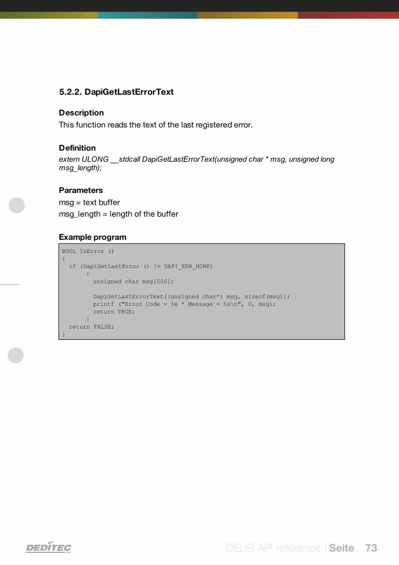
5.2.2. DapiGetLastErrorText
Description
This function reads the text of the last registered error.
Definition
extern ULONG __stdcall DapiGetLastErrorText(unsigned char * msg, unsigned longmsg_length);
Parameters
msg = text buffer
msg_length = length of the buffer
Example program
BOOL IsError (){ if (DapiGetLastError () != DAPI_ERR_NONE)
{ unsigned char msg[500];
DapiGetLastErrorText((unsigned char*) msg, sizeof(msg)); printf ("Error Code = %x * Message = %s\n", 0, msg); return TRUE;}
return FALSE;}
DELIB API reference | Seite 74
5.3. Reading Digital inputs
5.3.1. DapiDIGet1
Description
This command reads a single digit input.
Definition
ULONG DapiDIGet1(ULONG handle, ULONG ch);
Parameters
handle=This is the handle of an opened module.
ch=Specifies the number of input that is to be read (0 ..).
Return value
State of the input (0 / 1).

DELIB API reference | Seite 75
5.3.2. DapiDIGet8
Description
This command reads 8 digital inputs simultaneously.
Definition
ULONG DapiDIGet8(ULONG handle, ULONG ch);
Parameters
handle=This is the handle of an opened module.
ch=Specifies the number of the input, from which it begins to read from (0, 8,16, 24, 32, ..)
Return value
State of the read inputs.

DELIB API reference | Seite 76
5.3.3. DapiDIGet16
Description
This command reads 16 digital inputs simultaneously.
Definition
ULONG DapiDIGet16(ULONG handle, ULONG ch);
Parameters
handle=This is the handle of an opened module.
ch=Specifies the number of the input, from which it begins to read from (0, 16,32, ..)
Return value
State of the read inputs.
DELIB API reference | Seite 77
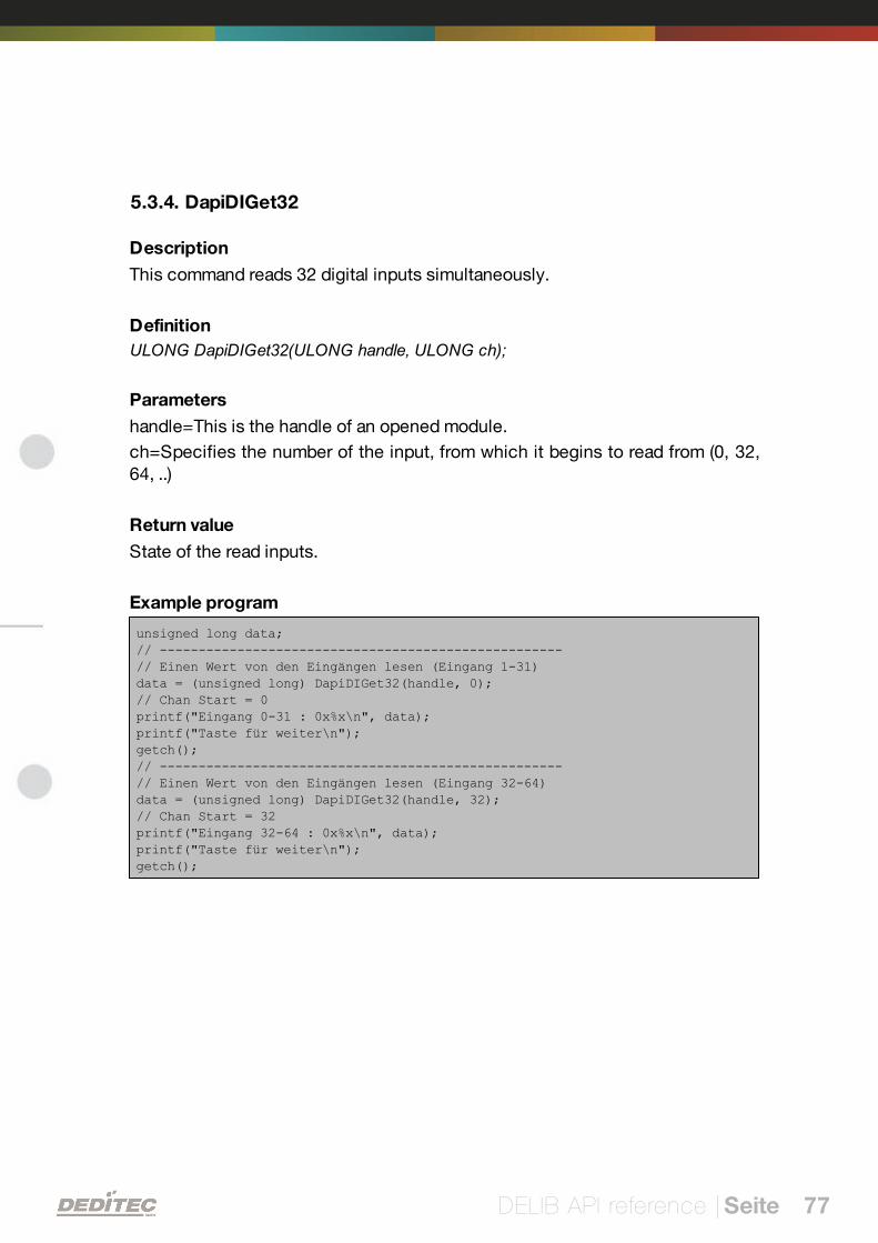
5.3.4. DapiDIGet32
Description
This command reads 32 digital inputs simultaneously.
Definition
ULONG DapiDIGet32(ULONG handle, ULONG ch);
Parameters
handle=This is the handle of an opened module.
ch=Specifies the number of the input, from which it begins to read from (0, 32,64, ..)
Return value
State of the read inputs.
Example program
unsigned long data;// ----------------------------------------------------// Einen Wert von den Eingängen lesen (Eingang 1-31)data = (unsigned long) DapiDIGet32(handle, 0);// Chan Start = 0printf("Eingang 0-31 : 0x%x\n", data);printf("Taste für weiter\n");getch();// ----------------------------------------------------// Einen Wert von den Eingängen lesen (Eingang 32-64)data = (unsigned long) DapiDIGet32(handle, 32);// Chan Start = 32printf("Eingang 32-64 : 0x%x\n", data);printf("Taste für weiter\n");getch();
DELIB API reference | Seite 78
5.3.5. DapiDIGet64
Description
This command reads 64 digital inputs simultaneously.
Definition
ULONGLONG DapiDIGet64(ULONG handle, ULONG ch);
Parameters
handle=This is the handle of an opened module.
ch=Specifies the number of the input,from which it begins to read from (0, 64, ..)
Return value
State of the read inputs.
DELIB API reference | Seite 79
5.3.6. DapiDIGetFF32
Description
This command reads the flip-flops from the inputs and resets them. (Input statechange).
Definition
ULONG DapiDIGetFF32(ULONG handle, ULONG ch);
Parameters
handle=This is the handle of an opened module .
ch=Specifies the number of the input, from which it begins to read from (0, 32,..)
Return value
State of 32 input change states
DELIB API reference | Seite 80
5.3.7. DapiDIGetCounter
Description
This command reads the counter of a digital input
Definition
ULONG DapiDIGetCounter(ULONG handle, ULONG ch, ULONG mode);
Parameters
handle=This is the handle of an opened module.
ch=Specifies the digital input,from which the counter will be read.
mode=0 (Normal counter function)
mode=DAPI_CNT_MODE_READ_WITH_RESET (Reading and resetting thecounter)
mode=DAPI_CNT_MODE_READ_LATCHED (Reading the latched counter)
Return value
Value of the counter.
Example program
value = DapiDIGetCounter(handle, 0 ,0);// Reading counter of DI Chan 0
value = DapiDIGetCounter(handle, 1 ,0);// Reading counter of DI Chan 1
value = DapiDIGetCounter(handle, 8 ,0);// Reading counter of DI Chan 8
value = DapiDIGetCounter(handle, 0 ,DAPI_CNT_MODE_READ_WITH_RESET);// Reading AND resetting counter of DI Chan 0
value = DapiDIGetCounter(handle, 1, DAPI_CNT_MODE_READ_LATCHED);// Reading the latched counter of DI Chan 1
DELIB API reference | Seite 81
5.3.8. DapiSpecialCounterLatchAll
Description
This command saves the counters of all digital inputs simultaneously into atemporary storage (latch).
So, after that, the counter of the latch can be read successively.
Here, the speciality is, that it is possible to "freeze" simultaneously the counterand the frozen counter (latch) can be read one by one.
Definition
void DapiSpecialCommand(ULONG handle, DAPI_SPECIAL_CMD_COUNTER,DAPI_SPECIAL_COUNTER_LATCH_ALL, 0, 0);
Parameters
None
Example program
DapiSpecialCommand(handle, DAPI_SPECIAL_CMD_COUNTER,DAPI_SPECIAL_COUNTER_LATCH_ALL, 0, 0);
DELIB API reference | Seite 82
5.3.9. DapiSpecialCounterLatchAllWithReset
Description
This command saves the counters of all digital inputs simultaneously into atemporary storage (latch).
In addition, the counters of the digital inputs will be reset.
Definition
void DapiSpecialCommand(ULONG handle, DAPI_SPECIAL_CMD_COUNTER,DAPI_SPECIAL_COUNTER_LATCH_ALL_WITH_RESET, 0, 0);
Parameters
None
Example program
DapiSpecialCommand(handle, DAPI_SPECIAL_CMD_COUNTER,DAPI_SPECIAL_COUNTER_LATCH_ALL_WITH_RESET, 0, 0);
DELIB API reference | Seite 83
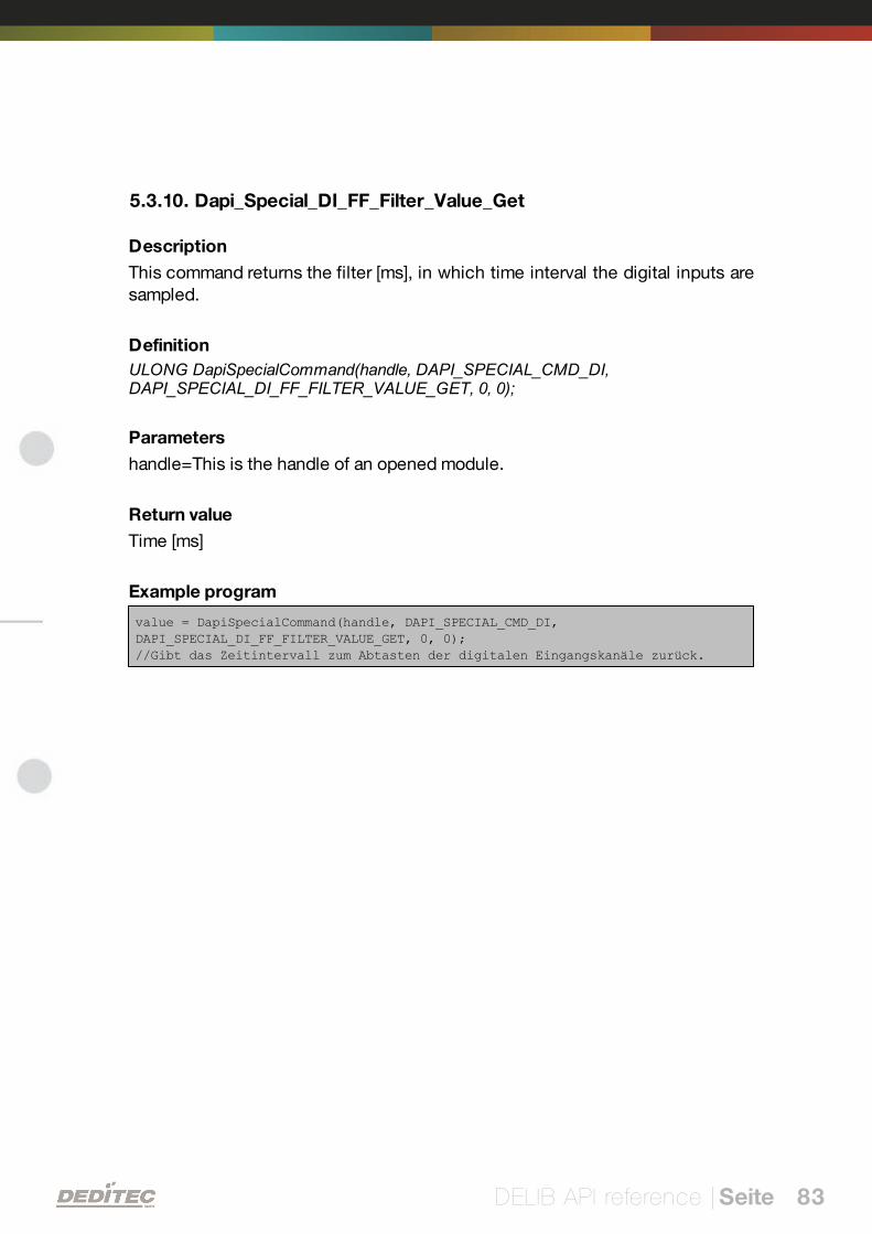
5.3.10. Dapi_Special_DI_FF_Filter_Value_Get
Description
This command returns the filter [ms], in which time interval the digital inputs aresampled.
Definition
ULONG DapiSpecialCommand(handle, DAPI_SPECIAL_CMD_DI,DAPI_SPECIAL_DI_FF_FILTER_VALUE_GET, 0, 0);
Parameters
handle=This is the handle of an opened module.
Return value
Time [ms]
Example program
value = DapiSpecialCommand(handle, DAPI_SPECIAL_CMD_DI,DAPI_SPECIAL_DI_FF_FILTER_VALUE_GET, 0, 0);//Gibt das Zeitintervall zum Abtasten der digitalen Eingangskanäle zurück.
DELIB API reference | Seite 84
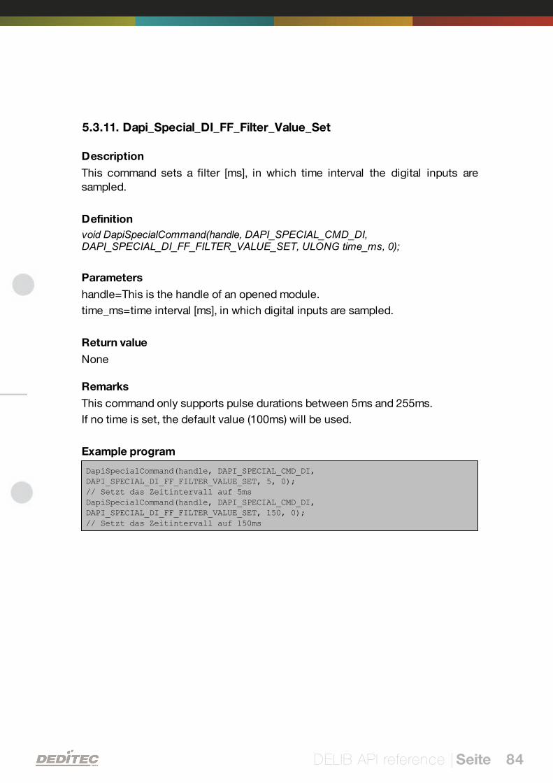
5.3.11. Dapi_Special_DI_FF_Filter_Value_Set
Description
This command sets a filter [ms], in which time interval the digital inputs aresampled.
Definition
void DapiSpecialCommand(handle, DAPI_SPECIAL_CMD_DI,DAPI_SPECIAL_DI_FF_FILTER_VALUE_SET, ULONG time_ms, 0);
Parameters
handle=This is the handle of an opened module.
time_ms=time interval [ms], in which digital inputs are sampled.
Return value
None
Remarks
This command only supports pulse durations between 5ms and 255ms.
If no time is set, the default value (100ms) will be used.
Example program
DapiSpecialCommand(handle, DAPI_SPECIAL_CMD_DI,DAPI_SPECIAL_DI_FF_FILTER_VALUE_SET, 5, 0);// Setzt das Zeitintervall auf 5msDapiSpecialCommand(handle, DAPI_SPECIAL_CMD_DI,DAPI_SPECIAL_DI_FF_FILTER_VALUE_SET, 150, 0);// Setzt das Zeitintervall auf 150ms
DELIB API reference | Seite 85
5.4. Setting Digital outputs
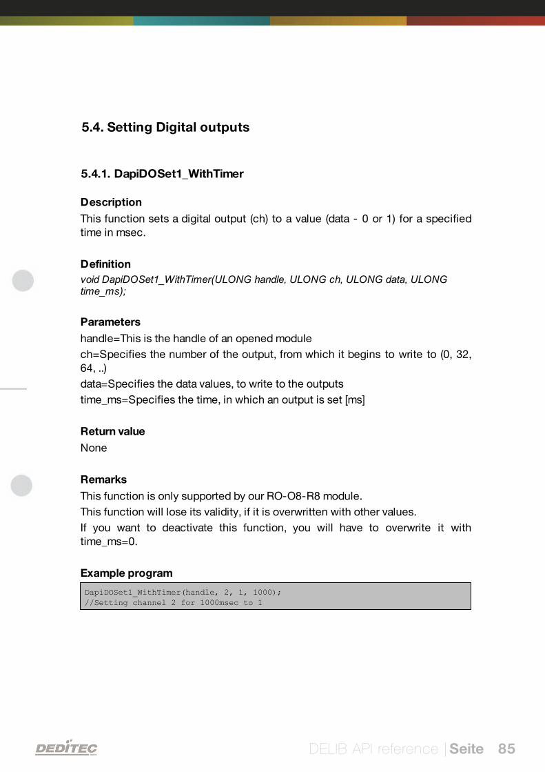
5.4.1. DapiDOSet1_WithTimer
Description
This function sets a digital output (ch) to a value (data - 0 or 1) for a specifiedtime in msec.
Definition
void DapiDOSet1_WithTimer(ULONG handle, ULONG ch, ULONG data, ULONGtime_ms);
Parameters
handle=This is the handle of an opened module
ch=Specifies the number of the output, from which it begins to write to (0, 32,64, ..)
data=Specifies the data values, to write to the outputs
time_ms=Specifies the time, in which an output is set [ms]
Return value
None
Remarks
This function is only supported by our RO-O8-R8 module.
This function will lose its validity, if it is overwritten with other values.
If you want to deactivate this function, you will have to overwrite it withtime_ms=0.
Example program
DapiDOSet1_WithTimer(handle, 2, 1, 1000);//Setting channel 2 for 1000msec to 1
DELIB API reference | Seite 86
5.4.2. DapiDOSet1
Description
This is the command to set a single output.
Definition
void DapiDOSet1(ULONG handle, ULONG ch, ULONG data);
Parameters
handle=This is the handle of an opened module
ch=Specifies the number of the output to be set to (0 ..)
data=Specifies the data value that is to be written (0 / 1)
Return value
None

DELIB API reference | Seite 87
5.4.3. DapiDOSet8
Description
This command sets 8 digital outputs simultaneously.
Definition
void DapiDOSet8(ULONG handle, ULONG ch, ULONG data);
Parameters
handle=This is the handle of an opened module
ch=Specifies the number of the output, from which it begins to write to (0, 8, 16,24, 32, ..)
data=Specifies the data values, to write to the outputs
Return value
None
DELIB API reference | Seite 88
5.4.4. DapiDOSet16
Description
This command sets 16 digital outputs simultaneously.
Definition
void DapiDOSet16(ULONG handle, ULONG ch, ULONG data);
Parameters
handle=This is the handle of an opened module
ch=Specifies the number of the output, from which it begins to write to (0, 16,32, ..)
data=Specifies the data values, to write to the outputs
Return value
None
DELIB API reference | Seite 89
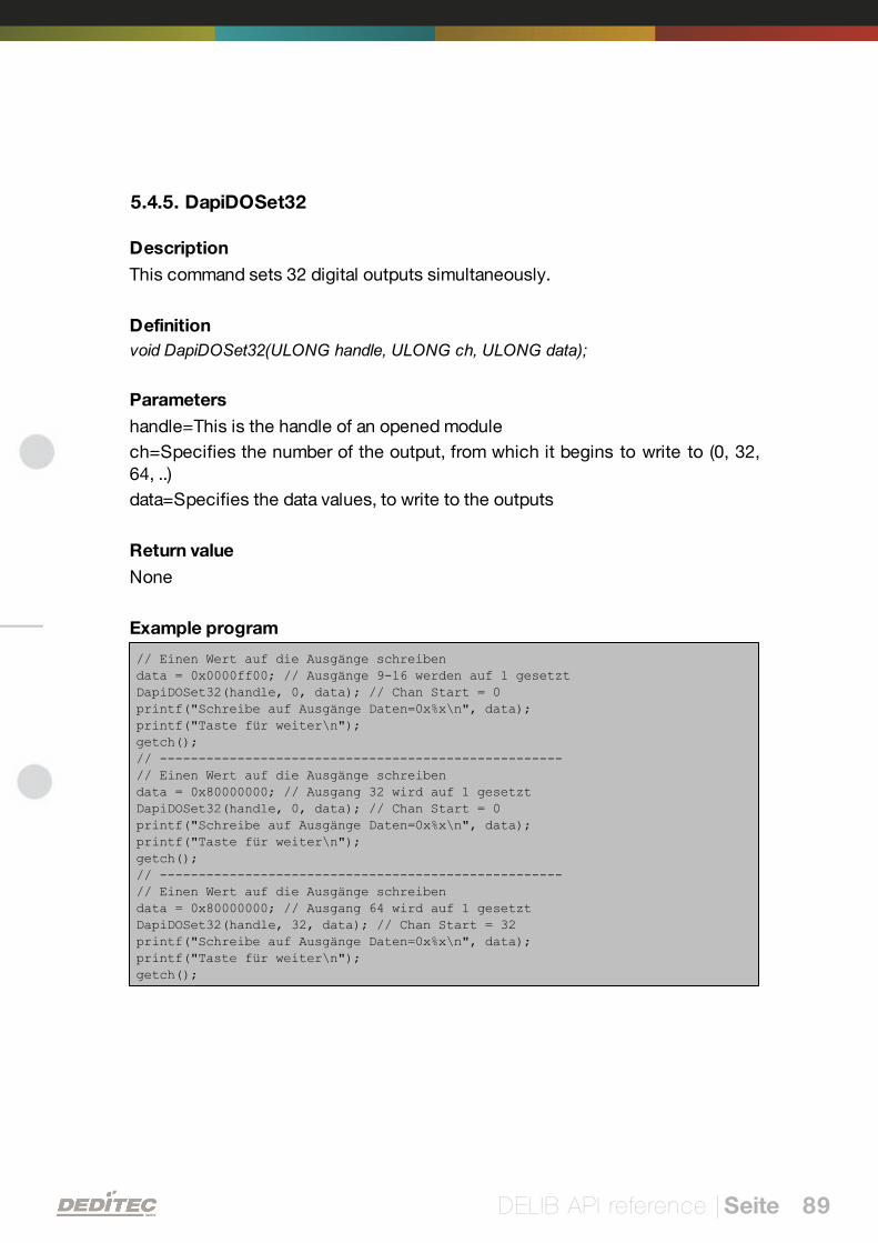
5.4.5. DapiDOSet32
Description
This command sets 32 digital outputs simultaneously.
Definition
void DapiDOSet32(ULONG handle, ULONG ch, ULONG data);
Parameters
handle=This is the handle of an opened module
ch=Specifies the number of the output, from which it begins to write to (0, 32,64, ..)
data=Specifies the data values, to write to the outputs
Return value
None
Example program
// Einen Wert auf die Ausgänge schreibendata = 0x0000ff00; // Ausgänge 9-16 werden auf 1 gesetztDapiDOSet32(handle, 0, data); // Chan Start = 0printf("Schreibe auf Ausgänge Daten=0x%x\n", data);printf("Taste für weiter\n");getch();// ----------------------------------------------------// Einen Wert auf die Ausgänge schreibendata = 0x80000000; // Ausgang 32 wird auf 1 gesetztDapiDOSet32(handle, 0, data); // Chan Start = 0printf("Schreibe auf Ausgänge Daten=0x%x\n", data);printf("Taste für weiter\n");getch();// ----------------------------------------------------// Einen Wert auf die Ausgänge schreibendata = 0x80000000; // Ausgang 64 wird auf 1 gesetztDapiDOSet32(handle, 32, data); // Chan Start = 32printf("Schreibe auf Ausgänge Daten=0x%x\n", data);printf("Taste für weiter\n");getch();
DELIB API reference | Seite 90
5.4.6. DapiDOSet64
Description
This command is to set 64 digital outputs.
Definition
void DapiDOSet64(ULONG handle, ULONG ch, ULONG data);
Parameters
handle=This is the handle of an opened module
ch=Specifies the number of the output, from which it begins to write to (0, 64, ..)
data=Specifies the data values, to write to the outputs
Return value
None
DELIB API reference | Seite 91
5.4.7. DapiDOReadback32
Description
This command reads back the 32 digital outputs.
Definition
ULONG DapiDOReadback32(ULONG handle, ULONG ch);
Parameters
handle=This is the handle of an opened module
ch=Specifies the number of the input, from which it begins to read from (0, 32,..)
Return value
Status of 32 outputs.
DELIB API reference | Seite 92
5.4.8. DapiDOReadback64
Description
This command reads back the 64 digital outputs.
Definition
ULONGLONG DapiDOReadback64(ULONG handle, ULONG ch);
Parameters
handle=This is the handle of an opened module
ch=Specifies the number of the input, from which it begins to read from (0, 64,..)
Return value
Status of 64 outputs.
DELIB API reference | Seite 93
5.5. Set TTL-In-/Outputs direction with DapiSpecialCommand
5.5.1. DAPI_SPECIAL_CMD_SET_DIR_DX_1
Description
This command sets the direction of the TTL-In/Outputs (1-Bit).
Definition
void DapiSpecialCommand(ULONG handle, DAPI_SPECIAL_CMD_SET_DIR_DX_1,ULONG ch, ULONG dir, 0);
Parameters
handle=This is the handle of an opened module.
ch=Specifies the number of the output, from which the direction should be set(0, 8, 16, 24..)
dir=Specifies the direction for 8 channels (1=output / 0=input) / Bit 0 signifieschannel 0, Bit 1 channel 1 ...
Example program
DapiSpecialCommand(handle, DAPI_SPECIAL_CMD_SET_DIR_DX_1, 0, 0x01 , 0);// Set Dir of TTL-I/O CH0 to output, others to inputDapiSpecialCommand(handle, DAPI_SPECIAL_CMD_SET_DIR_DX_1, 0, 0x02 , 0);// Set Dir of TTL-I/O CH1 to output, others to inputDapiSpecialCommand(handle, DAPI_SPECIAL_CMD_SET_DIR_DX_1, 0, 0x04 , 0);// Set Dir of TTL-I/O CH2 to output, others to inputDapiSpecialCommand(handle, DAPI_SPECIAL_CMD_SET_DIR_DX_1, 0, 0x08 , 0);// Set Dir of TTL-I/O CH3 to output, others to inputDapiSpecialCommand(handle, DAPI_SPECIAL_CMD_SET_DIR_DX_1, 0, 0x10 , 0);// Set Dir of TTL-I/O CH4 to output, others to inputDapiSpecialCommand(handle, DAPI_SPECIAL_CMD_SET_DIR_DX_1, 0, 0x20 , 0);// Set Dir of TTL-I/O CH5 to output, others to inputDapiSpecialCommand(handle, DAPI_SPECIAL_CMD_SET_DIR_DX_1, 0, 0x40 , 0);// Set Dir of TTL-I/O CH6 to output, others to inputDapiSpecialCommand(handle, DAPI_SPECIAL_CMD_SET_DIR_DX_1, 0, 0x80 , 0);// Set Dir of TTL-I/O CH7 to output, others to input
DapiSpecialCommand(handle, DAPI_SPECIAL_CMD_SET_DIR_DX_1, 0, 0x0f , 0);// Set Dir of TTL-I/O CH0-3 to output, others to inputDapiSpecialCommand(handle, DAPI_SPECIAL_CMD_SET_DIR_DX_1, 0, 0xff , 0);// Set Dir of TTL-I/O CH0-7 to output, others to input
DELIB API reference | Seite 94
5.5.2. DAPI_SPECIAL_CMD_SET_DIR_DX_8
Description
This command sets the direction of the TTL-In/Outputs (8-Bit way).
Definition
void DapiSpecialCommand(ULONG handle, DAPI_SPECIAL_CMD_SET_DIR_DX_8,ULONG ch, ULONG dir, 0);
Parameters
handle=This is the handle of an opened module.
ch=Specifies the number of the output,from which the direction will be set (0, 8,16, 24 ..). Values between are invalid.
dir=(8-Bit) gives the direction for 8 In/Outputs. (1=output / 0=input)
Example program
DapiSpecialCommand(handle, DAPI_SPECIAL_CMD_SET_DIR_DX_8, 0, 1, 0);
// Set Dir of TTL-I/O CH0 to out
DELIB API reference | Seite 95
5.6. Example program
// ****************************************************************************// ****************************************************************************// ****************************************************************************// ****************************************************************************// ****************************************************************************//// (c) DEDITEC GmbH, 2009//// web: http://www.deditec.de//// mail: [email protected]//////// dtapi_prog_beispiel_input_output.cpp////// ****************************************************************************// ****************************************************************************// ****************************************************************************// ****************************************************************************// ****************************************************************************////// Folgende Bibliotheken beim Linken mit einbinden: delib.lib// Dies bitte in den Projekteinstellungen (Projekt/Einstellungen/Linker(Objekt-Bibliothek-Module) .. letzter Eintrag konfigurieren#include <windows.h>#include <stdio.h>#include "conio.h"#include "delib.h"// ----------------------------------------------------------------------------// ----------------------------------------------------------------------------// ----------------------------------------------------------------------------// ----------------------------------------------------------------------------// ----------------------------------------------------------------------------
void main(void){unsigned long handle;unsigned long data;unsigned long anz;unsigned long i;unsigned long chan;// ----------------------------------------------------// USB-Modul öffnenhandle = DapiOpenModule(USB_Interface8,0);printf("USB_Interface8 handle = %x\n", handle);if (handle==0){// USB Modul wurde nicht gefundenprintf("Modul konnte nicht geöffnet werden\n");printf("TASTE für weiter\n");getch();
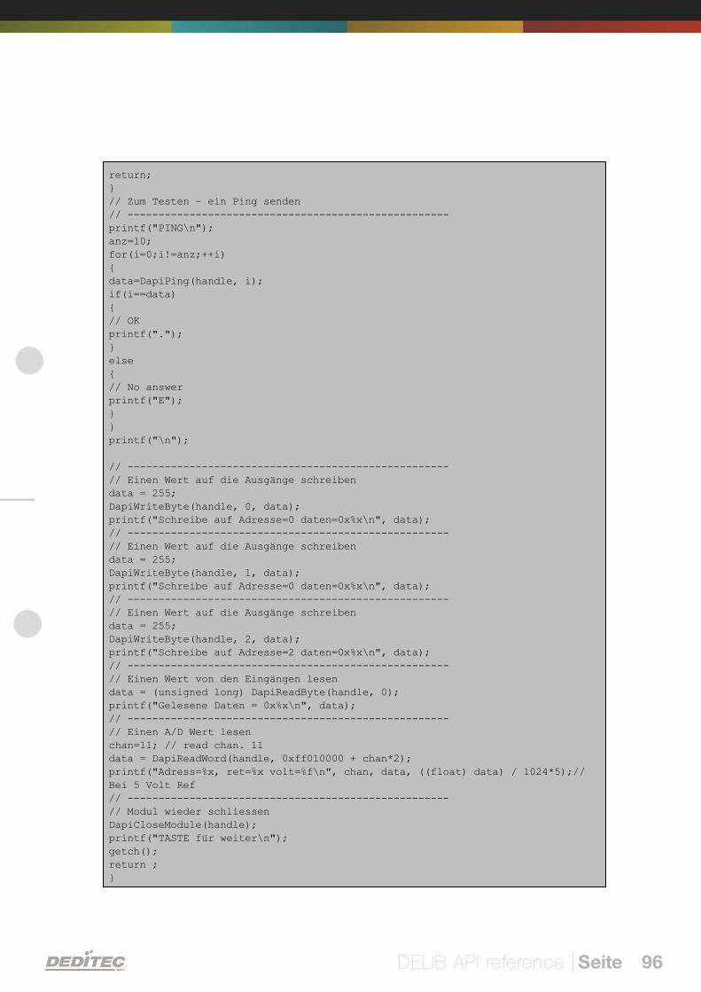
DELIB API reference | Seite 96
return;}// Zum Testen - ein Ping senden// ----------------------------------------------------printf("PING\n");anz=10;for(i=0;i!=anz;++i){data=DapiPing(handle, i);if(i==data){// OKprintf(".");}else{// No answerprintf("E");}}printf("\n");
// ----------------------------------------------------// Einen Wert auf die Ausgänge schreibendata = 255;DapiWriteByte(handle, 0, data);printf("Schreibe auf Adresse=0 daten=0x%x\n", data);// ----------------------------------------------------// Einen Wert auf die Ausgänge schreibendata = 255;DapiWriteByte(handle, 1, data);printf("Schreibe auf Adresse=0 daten=0x%x\n", data);// ----------------------------------------------------// Einen Wert auf die Ausgänge schreibendata = 255;DapiWriteByte(handle, 2, data);printf("Schreibe auf Adresse=2 daten=0x%x\n", data);// ----------------------------------------------------// Einen Wert von den Eingängen lesendata = (unsigned long) DapiReadByte(handle, 0);printf("Gelesene Daten = 0x%x\n", data);// ----------------------------------------------------// Einen A/D Wert lesenchan=11; // read chan. 11data = DapiReadWord(handle, 0xff010000 + chan*2);printf("Adress=%x, ret=%x volt=%f\n", chan, data, ((float) data) / 1024*5);//Bei 5 Volt Ref// ----------------------------------------------------// Modul wieder schliessenDapiCloseModule(handle);printf("TASTE für weiter\n");getch();return ;}
VI
Appendix | Seite 97
Appendix
Appendix | Seite 98
6. Appendix
6.1. Revisions
Rev 1.00 First issue
Rev 1.01 Revision of the block diagrams
Rev 1.10 DELIB Configuration Utility / Digital Input/Output Sample
Rev 2.00 Design change
Rev 2.01 New program example at command
"DAPI_SPECIAL_CMD_SET_DIR_DX_1"
Rev 2.02 Chapter "USB-MINI-REL4" added
Rev 2.03 Added chapters "Firmware update" and "Integration of theDELIB"
Rev 2.04 Added index
Appendix | Seite 99
6.2. Copyrights and trademarks
Linux is registered trade-mark of Linus Torvalds.
Windows CE is registered trade-mark of Microsoft Corporation.
USB is registered trade-mark of USB Implementers Forum Inc.
LabVIEW is registered trade-mark of National Instruments.
Intel is registered trade-mark of Intel Corporation
AMD is registered trade-mark of Advanced Micro Devices, Inc.