Embed Size (px)
Citation preview

USE & CARE
Model AE (8")
Model AF (10")

-2-
Dear CustomerCongratulations on the purchase of your new Delta-Q Autoclave. The technical documentation provided is designed as a part ofthis product. Always keep this documentation handy. The Use & Care Manual describes the 8” and 10” models. Please read theinstructions and get to know the autoclave. Please carryout maintenance according to relevent instructions.Pelton & Crane
Important Safety Instructions ..................................................................................................................................................... 3Familiarization ............................................................................................................................................................................. 6
Operating Features ............................................................................................................................................................. 6Safety Features .................................................................................................................................................................. 6Visual Displays ................................................................................................................................................................... 4Switch Functions ................................................................................................................................................................ 6Audible Signals ................................................................................................................................................................... 8Program Parameters ........................................................................................................................................................... 8
Installation .................................................................................................................................................................................... 9
Programming ............................................................................................................................................................................. 10Operation ................................................................................................................................................................................... 11
Important Sterilization Practices ........................................................................................................................................ 11Preparation and Loading ................................................................................................................................................... 12Operating Steps ................................................................................................................................................................ 13
Maintenance ............................................................................................................................................................................... 14Maintenance and Performance Schedule .......................................................................................................................... 14Cleaning Procedure .................................................................................................................................................... 15 -16Trouble Shooting Guide ..................................................................................................................................................... 17Self-Diagnostic Check ...................................................................................................................................................... 19Operating Alarms .............................................................................................................................................................. 20
Options ....................................................................................................................................................................................... 21Installation and Servicing Checklist ......................................................................................................................................... 22
TABLE OF CONTENTS

-3-
! IMPORTANT SAFETY INSTRUCTIONS !
Caution! Personal Safety• To avoid electrical shock, never insert plug into outlet with
wet hands.• Do not attempt to open door unless pressure gauge reads
“0” or injury may result.• Do not operate Autoclave in area containing combustible
gases.• Do not place Autoclave within 6 feet of patient.• Routinely inspect power cord for cuts and abrasions.
Discontinue use and have authorized service representa-tive replace cord if damaged.
• Protect your hands from contact with soiled instruments toprevent serious infections. Wear heavy rubber gloves whenhandling instruments.
Warning! To Avoid Serious Burns:Do not open door during sterilization cycle.Stand to one side when opening door aftersterilization cycle and do not place hands orface over door.
- Use a tool or hot pad to remove trays and avoidtouching chamber walls.
- Stand away from door after the sterilization cycle iscompleted. Liquids may still be in the chamber andcan cause serious burns.
- Ensure unit is properly leveled. Follow the Installa-tion Instructions on page 9.
- When performing safety valve maintenance (pg. 14)stand clear of discharge area (lower right corner atrear of unit).
Interference with electromedical devices:To guarantee the operational safety of electromedical devices,it is recommended that the operation of mobile radio tele-phones in the medical practice or hospital be prohibited.
Strong EMI sources such as electro surgery units or x-rayunits may effect performance. If performance problems occur,move the unit to another electrical circuit or physical location.
WARNING: If unit is operating in high altitude,adjustments to time, temperature or pressuremay be required. Also, leaking of safety valvemay indicate need for adjustment.
Product Disposal
Caution!Contact your local authorizeddealer for proper disposal of thedevice or the components of thedevice to ensure compliance withyour local environmental regula-tions.
Caution! Check weekly for properdoor switch operation (see pg. 14).
Product Safety• This unit requires a dedicated circuit (separate branch circuit
only).• Always use distilled quality water. Tap water will cause
corrosion of chamber and clog valves and filters with mineraldeposits.
• Never operate unit outside the specified voltage range (seedata plate on back of unit).
• Do not use steel wool or steel brushes on stainless steel.Metal pads will damage chamber.
• Use only manufacturer’s replacement parts/accessories.Failure to do so may cause poor performance.
• Refer servicing to authorized service representative.• Do not position the unit so that it is difficult to reach the
circuit breaker on the power plug.
Do not remove cover: Electrical shockhazard. Refer servicing to authorizedservice representative . Disconnect powerbefore servicing.
DANGER: Do Not attempt to open door withpressure in the chamber. Avoid direct con-tact with hot chamber walls or sterilized load.Use metal handle (8” model only) and gloves.
Warning! —To avoid serious burns —If used for liquid sterilization, the liquidmust be allowed to cool or the liquid mayboil when exposed to atmospheric pres-
sure. Pelton & Crane does not recommend use ofthis device for liquid sterilization.
CAUTION: ANY LIQUIDS THAT ARE STERILIZEDIN THIS UNIT ARE FOR LABORATORY USEONLY AND NOT FOR USE IN DIRECT PATIENTCONTACT.

-4-
Table of Symbols
Power
Ground
Mode
Printer Connection
Clear/Start
Program
Hot Surface
Low Water
Arrows
Attention: Printer Connection Only
Ready
Sterilize
Printer On/Off
Dry
The conformity of the quality management system is certified with Certificate No. 369CE, dated April 8, 1999 by:AMTAC Certification Services, LTDNorman Road, Broadheath, AltrinchamCheshire WA 14 4EP, United Kingdom
PRODUCT INFORMATION
CAUTION. Failure to carefully follow thedescribed procedure may result in damageto the equipment.
WARNING. Failure to carefully follow thedescribed procedure may result in damageto the equipment and the operator.
Risk of electrical shock present. Make surepower is disconnected before attempting thisprocedure.

-5-
8” Model
10” Model
PRODUCT INFORMATION
Exterior Dimensions8” Model-12 1/4” high x 20 1/4” deep x 17 1/2” wide(31.1 cm high x 51.4 cm deep x 44.5 cm wide)10” Model-14” high x 24 5/8” deep x 19 1/4” wide(35.6 cm high x 62.5 cm deep x 48.9 cm wide)
Chamber Dimensions8” Model-8 7/32” inside diameter x 14” useable depth(21 cm inside diameter x 35.6 cm deep)10” Model-9 7/8” inside diameter x 17 7/16” useable depth(25.1 cm inside diameter x 44.3 cm deep)
Weight Without Water in Reservoir8” Model-61 lbs. (28 kg)10” Model-84 lbs. (38 kg)
Measurement AccuracyPressure: +/- 8 kPa (1.16 PSI or .08 bars)Temperature: +/- 3.6° F (2° C)Time: +/- 1 second
Power SupplyBoth Models-110 - 120 Volts, 50/60 Hz or220 - 240 Volts, 50/60 Hz
Nominal Current Consumption8” Model-12 Amperes @115 Volts6 Amperes @230 Volts10” Model-10 Amperes @115 Volts8 Amperes @230 Volts
Environmental and Storage LimitationsBoth Models-Optimum Operating Temperature Range:50°F to 104°F(10°C to 40°C)Relative Humidity Range:30% to 75%Unit is designed for normal dental/medical office environ-ment.NOTE: If printer is used, its operating temperature is 41°Fto 95°F (5°C to 35°C).Mode of Operation:Both Models- ContinuousNOTICE: Manufacturer will make available all informationwhich will assist the authorized service representative torepair equipment. Calibration of the power board is to bedone only at the factory.
Specifications
12 1/4”
(31.1cm)
17 !”
(44.5cm)
20 1/4”
(44.5cm)
14”
(35.6cm)
19 1/4”
(48.9cm)
24 5/8”
(62.5cm)

-6-
OPERATING FEATURES1. Power Switch/Circuit Breaker (rear of unit)
2. Reservoir Fill3. Operation Indicator Light4. Display Window (Pressure) kPa5. Arrow Switches6. Display Window (Temp/Time) C/F / Minutes7. Clear/Start Switch8. Low Water Light9. Mode Selection Switch
10. Mode/Program Display11. Power On Switch12. Programming Switch13. Printer On/Off Switch14. Quick Drain Connection (inside door)15. Leveling Feet16. Door Lock17. Safety Valve (rear corner of unit)18. Operating Instructions Label19. Caution Label20. Serial Number Plate (inside door).
FAMILIARIZATION
SAFETY FEATURESThe design of the autoclave has these safety features foryour protection:Door LockDoor can be opened only when internal pressure is atatmospheric pressure.Vent ValveThe vent valve will open and the P-2 alarm will display shouldthe chamber pressure exceed 240 kPa.Safety ValveThe safety valve opens as backup protection should thechamber pressure exceed 262 kPa.Overheat ProtectionChamber temperature is protected with a surface sensor sothe temperature will not exceed 159°C. It has additionaloverheat protection should the temperature of the heatingelements reach 180°C.Electrical Power InterruptionIn case of a power failure during the sterilization cycle,pressure in the chamber is automatically vented to theatmosphere and display is blank
20
2
345
6
5
7
8
9
1011
12
13
15
19
18
17
15
14

-7-
FAMILIARIZATION
VISUAL DISPLAYSIndicator Lights“Sterilize” light illuminates to indicate sterilization cycle in progress.
“Dry” light indicates the heater and pump are on for the drying cycle.
“Ready” light illuminates when instruments may be removed from chamber.
Upper WindowDisplays Time, Pressure, Clock and Year.
Lower WindowDisplays Temperature, Date, Operational Timer, Failure Codes, Power colon “:” (power button is not activated when main power is ON) and End.
Mode/ProgramSee Program Parameters, pg. 10.
Low WaterWhen the water level in the reservoir is too low, the “Low Water” light illuminates.
SWITCH FUNCTIONS
ArrowsIncreases or decreases values of digits flashing when programming the systemparameter.
Clear/StartControls the start of a sterilizing cycle when unit is in stand-by. Also, used to cleara cycle and returns unit to stand-by. If depressed with “Power” switch, self-diag-nostic check is performed.
Mode SelectionPress to select one of the five sterilization mode programs. (See page 14 forspecial mode)
Printer On/OffUse to switch the printer on or off.
ProgramSets the minutes, hour, day, month and year. Chooses units of temperature andpressure. Changes the drying time. Also, chooses the Special mode to the param-eter desired. It initiates selected display mode during sterilization.
PowerPowers on operating controls. LCD will be visible. If depressed with “Clear/Start”switch, self-diagnostic check is performed.
Main Power (back of unit)Depress “I” side of switch to turn unit on. A colon “:” illuminates in the lowerdisplay indicating power is on. Leave switch in the On position.

-8-
FAMILIARIZATION
* For mixed loads, use the longer or lower temperature program (i.e., for loose instruments and surgical dressings in packs, use“3 Packs”).
** Time and temperatures are minimums.*** When sterilizing handpieces, check handpiece manufacturer’s recommendations for appropriate sterilization conditions. Use “2
Wrapped” program only if handpieces are able to withstand 134°C-137°C temperature.The names of the various modes of operation are general categories.When selecting the mode of operation, take into consideration the density of the individual load and the ability of the steam tocirculate and penetrate wraps. Then determine the correct programmed values to assure sterilization.
Items to be SterilizedProgram/Temp**, Pres,Time**
1 Unwrapped/134°C, 216 kPa for 3minutes
2 Wrapped/134°C, 216 kPa for 12minutes
3 Packs/121°C, 115 kPa for 30minutes
4 Liquids/121°C, 115 kPa for 30minutes
5 Special/Programmable to101°C to 135°C, for 1to 90 minutes.
Instruments loose on a tray. Open glass or metal canisters. Heat-resistant rubber tubingwhich will not be used in surgical procedure. Any items where 134°C-137°C for 3 minutesis appropriate.Loosely wrapped individual instruments.
Wrapped dental handpieces***. Multiple layers of instruments separated by fabric. Instru-ments in pouches. Wrapped tray of loose instruments. Heat-resistant rubber tubing. Anyitems where 134°C-137°C for 12 minutes is appropriate.
Common groups of surgical instruments in commercially prepared packs. Surgical instru-ments subject to prolonged storage. Any items, other than liquids, where 121°C for 30minutes is appropriate.
Liquids or gels that could boil or spill out of container. At end of sterilizing cycle, venting isslowed to allow heat in liquid to dissipateslowly and eliminate boilovers. Venting occurs at 20 kPa to complete the cycle. There isNO drying cycle in the “Liquids” mode.
!CAUTION: ANY LIQUIDS THAT ARE STERILIZED IN THIS UNIT ARE FORLABORATORY USE ONLY AND NOT FOR USE IN DIRECT PATIENT CONTACT.
Dependent upon parameters user has programmed. Operator is responsible for correcttime and temperature settings for load.
AUDIBLE SIGNALSSwitchesOne beep occurs when depressing switches, except when depressing Power Switch and Arrow switches. When pressingArrow or Power Switch, no beep occurs.Sterilization/Dry CycleFive beeps indicate the Sterilization or Drying cycles are complete.
Operational AlarmSixty beeps indicates an operational error or alarm. Depress Clear/Start to put unit in standby mode.
Door OpenContinuous beeping indicates the door has been opened during or prior to start of cycle.
PROGRAM PARAMETERS*
Warning! —To avoid serious burns —If used for liquid sterilization, the liquid must be allowed to cool or the liquidmay boil when exposed to atmospheric pressure. Pelton & Crane does notrecommend use of this device for liquid sterilization.

-9-
1. Remove all packing material from chamber.
2. Place unit on a level countertop.
3. Peel protective cover from tape on top of casing andplace operating instruction card (B) (with theappropriate language for the operator, facing up) onthe tape and press down firmly.
NOTE: If unit has been stored in cold condi-tions, allow it two hours to warm up to roomtemperature before operating.
4. Plug power cord into a receptacle that is on adedicated. Ensure that the circuit has the properfuse or breaker to accomodate the maximum powerof the unit. Properly install per you local electricalcodes. (See illustration C).
5. This unit has been pre-leveled during manufacturingtherefore “NO” leveling is required. However, if theunit is placed on a surface that is not level thenfollow the leveling instructions below:
• Remove all trays from the chamber.
• Pour distilled water into chamber.
• Adjust leveling feet (D) until water comes to the pulltab of the inline filter assembly (F) (located in therear of chamber) and reaches the top of water dam(G) at the front of chamber.
• Reinstall trays and tray rest.
• Close door and run one cycle on the unwrappedcycle according to the operating instructions.
IMPORTANT: Carefully read the ProgrammingSet-up instructions and program unit accord-ingly. (Refer to page 14).
NOTE: The unit has a special automatic preheatmode that warms chamber for quicker cycletimes, between 0600 and 1800 hours.
NOTE: If unit is not to be used for extendedperiod of time. Turn OFF main power switchlocated in the back of unit.
INSTALLATION
(813mm - 914mm)
C
Power Cord Configurations and Ratings.
D
G
F
B
WARNING: Counter top must be wide enoughto support all unit feet. All unit feet must besecurely placed on counter top.
115 V15 AMP
115 V20 AMP
220 V13 AMP
NorthAmerica

-10-
PROGRAMMING
Hours (based on military time) andmonth (ranges 1 - 12) display flashes.
Minute (ranges 00 - 59) and Day(ranges 1 - 31) display flashes.
Year (ranges 00 - 99) and Minute or Yearand Temperature display flashes.
Unit of Measure Indicator for Pressure(kPa, PSI or Bars) and Unit of MeasureIndicator for Temperature (C or F)display flashes.
“Special” Program mode flashes.Current settings for Time and Tempera-ture of Special Program are displayed.
“Dry” indicator light flashes. Minutes(ranges 0-99) display flashes. (30Minutes is the recommended minimumtime which is preset at the factory.)
1. Depress “Program” button. Use Ar-rows to increase or decrease Timeand Month to correct settings.
Note: Properly program the time,since preheat starts 0600 hoursand stops at 1800 hours.
2. Depress “Program” button a sec-ond time. Use Arrows to increaseor decrease Minute and Day to cor-rect settings.
3. Depress “Program” button a thirdtime. Use Arrows to correctly setYear and choose to display the Min-utes remaining in the sterilizationcycle or the Temperature duringcycle.
4. Depress “Program” button a fourthtime. Use Arrows to select pre-ferred Pressure and Temperatureunit of measure for display.
5. Depress “Program” button a fifthtime. Use Arrows to increase or de-crease Time and Temperature set-tings for programming “Special”mode.
6. Depress “Program” button a sixthtime. Use Arrows to increase or de-crease Time for Drying cycle.
Operator Action System Response

-11-
OPERATION
• Do Not overload chamber. Refer to “Preparation and Loading”.Do not exceed maximum loading configuration. Otherwise, in-adequate sterilization could result.
• All functions of the sterilizer should be monitored to providemaximum sterility assurance. We recommend using Pelton &Crane’s printer to provide a permanent record of actual expo-sure times and temperatures.
• For additional assurance that minimum sterilizing conditionshave been achieved, good sterilization practices recommendthe use of a quality temperature sensitive process indicator witheach cycle and within each package.
• Since temperature sensitive process indicators do not integratesterilization parameters, biological monitoring is recommendedto provide further information in detecting inadequate sterilizerperformance. Biological indicators can be used to integrate thevarious cycle parameters and indicate whether sterilizationconditions have been met in a particular cycle.
• Thoroughly clean instruments before placing them in the steril-izer. Processing instruments with debris or blood contamina-tion impedes sterilization and may result in staining and/or dam-age to instruments or sterilizer. Use no cleaners with chlorine.
• Follow manufacturer’s recomendations for the individual itemsbefore sterilizing.
• Use proper sterilization and instrument handling as recom-mended by ADA, CDC, AAMI, AORN and OSAP guidelines.
• Do Not use staples, pins or other devices which will punc-ture the packaging material as sterility may be compromised.
• Do Not sterilize instruments while running cleaning cycle.• Sort instruments by type of metals. Do Not mix carbon steel
stainless steel, brass, aluminum, chrome or other types ofmetals as plating may occur.
• Place loose instruments on towel or absorbent paper.• Wrapped packages Must Not touch sides.• Place pouches with paper side down.• Place open containers tilting downward in tray.• Do Not attempt to sterilize long tubing as steam may not
penetrate the full length.• Do Not wrap instruments too tightly. Inadequate steriliza-
tion may result from improper wrapping or placing too manyinstruments per package.
• Use internal sterilization process indicators inside all sterilizerloads to verify gross heat penetration.
• Once per week, use a biological spore test indicator (BI) de-signed for gravity steam sterilizer operating at 121°C (Attest®,Biological Monitoring System, 3M, St. Paul, MN; or equivalent)or 134°C (EZ Test, Bozeman, MT) to test each type of cycleused at your facility.- Load sterilizer to maximum load used at your facility.- For “Wraps” and “Packs” Cycle, place biological indicator in-
side wrap or pack containing instruments and then place thispack or wrap in front lower tray of the sterilizer. (This is thecold spot, i.e. lowest temperature condition.)
- For Unwrapped Cycle, load trays with instruments, place bio-logical indicator in front lower tray of sterilizer.
Important Sterilization Practices
Sterilization Assurance
Follow manufacturer’s instructions for using all test materi-als and maintaining good clinical records.
• Follow Maintenance schedule on page 24 to ensure properoperation of the autoclave.
• Note: Indicator tape should not be used as a steriliza-tion indicator. It has a temperature sensitive stripe thatchanges color with temperature only.
Techniques for Sterilization Assurance
Clinical Record Keeping• Review daily and weekly records to substantiate procedures taken to assure sterilization.
Caution! Become familiar with theindividual functions of the five (5)modes to ensure using propersterilization cycle. Wrong modeselection or improper loading mayresult in improper sterilization.
CAUTION: ANY LIQUIDS THAT ARESTERILIZED IN THIS UNIT ARE FORLABORATORY USE ONLY AND NOT FORUSE IN DIRECT PATIENT CONTACT.

-12-
OPERATION
Preparation and Loading• Clean and dry items thoroughly.• Properly seal items in wrap or pouch if load is tobe kept sterile during storage. Recommended wrap/pouch materials are cloth, paper, or paper/polypouches. Nylon pouches/tubing are not recom-mended.• This unit is not suitable for sterilization of gowns/fabrics, “porous load”.• Place temperature sensitive process indicator in-side package.• Place temperature sensitive indicator in front por-tion of bottom tray.• Place load on tray with space between instru-ments or packages so that steam can flow be-tween items.• Place trays in chamber with adequate space forsteam circulation.
The Following are recommended maximum loading configurations:
Wrapped/Unwrapped Cycle• Model AE: Total weight not to exceed 1.5 lbs. This is equivalent to approximately 9 handpieces or hinged instruments (averageweight of 2.3 ounces) or 30 hand instruments (average weight of 1 ounce.)
• Model AF: Total weight not to exceed 2 lbs. This is equivalent to approximately 13 handpieces or hinged instruments (averageweight of 2.3 ounces) or 42 hand instruments (average weight of 1 ounce.)
Pack s CycleNOTE: When calculating maximum load, use the same weight and instrument equivalencies as specified in the “Wrapped/Unwrapped”cycle.• Model AE: Total weight not to exceed 2.5 lbs. One (1) pack in top tray and one (1) in bottom tray with pack dimensions not to
exceed 5! x 7! x 1/4!.• Model AF: Total weight not to exceed 2.5 lbs.. Two (2) packs in top tray and one (1) in bottom tray with pack dimensions not to
exceed 5! x 7! x 1 1/2!.
CAUTION: ANY LIQUIDS THAT ARE STERILIZED IN THIS UNIT ARE FORLABORATORY USE ONLY AND NOT FOR USE IN DIRECT PATIENT CON-TACT.Dental Handpieces: Check handpiece manufacturer’s recommendations forappropriate sterilization conditions. Use “2 Wrapped” program only ifhandpieces are able to withstand 134°C - 137°C temperatures.

-13-
Operating StepsNOTE: Add distilled water to bottom of filler cup
opening. Ensure water is covering condenser coilfor proper operation.
Add distilled water to reservoir between cycles if“Low Water” light is on. Close and latch door.
• At start of day, depress “Power” switch(A) to provide power to operating system.
• Ensure proper mode (B) is selected forload to be sterilized.
• Depress “Clear/Start” (C) switch. Unitwill automatically fill; build up steampressure while expelling air; sterilize forselected time; vent and dry for theprogrammed drying time.
• Open door and unload after drying cycle iscomplete: “Ready” light (D) is on; five beepsoccur; zero (0) pressure indicated in upperdisplay window (E) and “End” is displayed inlower display window (F) if door is not openedprior to completion of drying cycle.
• Note: Do not run sterilization cycle with dryinguntil the unit has preheated for 30 minutes. Other-wise, inadequate drying may occur.
• Note: Sterilized items may be removed anytime during the drying cycle. Use caution as itemsmay be hot and wet. Wet items will not remainsterile for any length of time.
• Important: Examine each pouch before andafter the sterilization cycle for open seals or tears.If there is a breach of pouch integrity, reseal in anew pouch and resterilize.
OPERATION
E
C
A
B
F
D
(power switch for main powersupply is located on thebackside of unit)
CAUTION: “5 Special” temperatures set below121°C should not be used for sterilization, butfor disinfection only.
WARNING: Do Not attempt to open door withpressure in the chamber. Avoid direct contactwith hot chamber walls or sterilized load. Usemetal handle and gloves.
-14-
MAINTENANCE
Maintenance and Performance Check ScheduleCHECK ACTION
Clean chamber
Door gasket
See “Cleaning Procedures” on pg. 15.
Call authorized service representativefor replacement gaskets.
NOTE: For proper operation use onlyour replacement parts availablethrough authorized service dealers.
It is recommended that you annually have your sterilization system inspected by an authorized service and retain maintainedrecords for the following:1. Hi-Pot Test2. Terminal Inspection3. Internal Tubing inspection for leaks.4. Filter replacements.5. Ground continuity test.6. Internal wire inspection for frayed wire.Note: For detailed service instructions, refer to autoclave Service Manual.
FREQUENCY PROCEDURE
4 ozs. Omni-Cleaner Plus® per 64 ozs. distilledwater.
Inspect and clean using Omni-Cleaner Plus® or milddetergent and water. Check for leaks and have leakinggasket replaced.
WARNING: Leaking gasket could result in harmto the operator because of escaping steam.
Call authorized service representative if improperclosure or signs of wear are noted.
Bio Indicator If test fails, do not use other items in with thatload. Ensure that “Important Sterilization Practices”and “Preparation and Loading” sections in thismanual have been followed.Retest using an empty chamber, then retest withproperly packaged and loaded chamber.If test still fails, discontinue using sterilizer andcontact an authorized service representitive.
Conduct testing using biological spore test indicator asdescribed in “Operation, Sterilization Assurance.”
Water filters
Door switch
Boiler ring
Call authorized service representative.
Call authorized service representativeif failure occurs.
Clean using non-chlorinated padwhich contains no metals.
With door open, attempt to start cycle. If door alarm doesnot appear on alarm display, door switch is defective orrequires adjustment. Unit should not operate.
Inspect for deposits.
Remove filter in chamber. Put filter in unltrasonic cleaner.Scrub with small soft brush under running water andreplace filter. When replacing, make sure filter in cham-ber touches center bottom wall of chamber to ensureproper draining.
Air filter
After every25 cycles
Weekly
Weekly
Monthly
Weekly
Weekly
Weekly
Every Ser-vice Call
Inspect air filter for cracks and loose tubing con-nections.
Have service representive removethe cover and inspect.
Call authorized service representive.Annually Replace Filter
If valve does not open or does notcompletely seal off after operation,turn off “Power” and call authorizedservice representative for replace-ment.
Manually pull ring (located on upper rear of chamber)when chamber pressure reaches 121 kPa. When pres-sure is relieved, valve automatically retracts.
Every 3months
Safetyvalve ring
WARNING: When ring is pulled on safety valvewith unit under pressure, steam is dischargedfrom the chamber straight down the pipe at hightemperature. When you pull ring, steam exitsout bottom. Make sure path is clear and thatyour hand is out of the way.
Operationcheck
Perform test described on page 11.
Inspect latch mechanism for signs of wear or improperclosure.
WeeklyDoor latch
CAUTION: Units is in preheat mode between 0600 - 1800 hours. So that units will be cool to the touch, turn off unit atmain power switch (back of unit) 30 minutes before performing maintenance.
If filters are clogged are will not clean,call an authorized service represen-tative for replacement filters.
CAUTION: Unauthorizedmaintenance can damagesterilizer and will voidmanufacturers warranty

-15-
Cleaning ProceduresNOTE: Proper cleaning at regular intervals isessential, since mineral deposits, debris or trashmay cause the unit to malfunction.
Draining ReservoirWith the door open, locate the quick drain connection(A) at the lower right corner of the face plate. Pressthe drain tube connector (B) provided with the unit intothe connection onthe face plate. This opens the drain line and draining ofthe reservoir will begin immediately.
Normal Chamber CleaningDrain the reservoir using quick connect drain tube. MixOmni-Cleaner Plus® with distilled water according to di-rections on bottle. Pour into reservoir. Run one “Un-wrapped” cycle (Note: It is not necessary to completedrying cycle). Drain reservoir. With the drain tube inplace, pour one to two gallons of water into the reservoiruntil the drained water is clear.This will remove excess suds. Wipe inside of the cham-ber with soft cloth.
WARNING: Do Not sterilize instrumentswhile cleaning autoclave.
Pour half gallon distilled water into reservoir. Run one“Unwrapped” cycle(Note: It is not necessary to complete dryingcycle). Wipe the inside of the chamber, the boiler ring(C) and the door gasket. Fill reservoir with distilledwater. Autoclave is ready for use.
Cleaning Deposits and Discoloration on StainlessSteelFor deposits not removed by detergent solution, use anon-chlorinated, non-metallic scouring pad such asScotch-Brite® or a powder such as Bon-Ami®.
CAUTION: Do not use ordinary steel woolor steel brushes on stainless steel. Padscontaining metal will damage chamber andcause instruments to be stained with rust.
CAUTION: Do not use chlorinatedcleaners. Doing so will cause corrosion.
Rub in direction of pattern or grain of the metal. Cleanstainless steel surfaces contaminated with discolorationwith a 5% solution of warm oxalic acid.
MAINTENANCE
B
A
C

-16-
Cleaning Procedures (cont’d)
Cleaning Boiler Ring (C)Clean boiler ring using a non-chlorinated, non-metallic scouring pad such as Scotch-Brite®.
Cleaning Door Gasket (D)Clean door gasket with Omni-Cleaner Plus® ornon-chlorinated detergent and water. Note: Ifresidue is allowed to accumulate, the seal couldbe affected and leaks may occur.
Cleaning/Disinfecting Exterior SurfacesClean all exterior surfaces with mild detergent andwater using a sponge or cloth. Disinfect exteriorsurfaces using an iodophor (Biocide, Biotrol, Inc.,or equivalent).
CAUTION: Do Not use any disinfectant oninterior stainless steel surface. Damage tothe chamber and/or trays may result.CAUTION: Do not use instruments if unitfails to complete cycle.
MAINTENANCE
D
C
B
A
-17-
MAINTENANCE
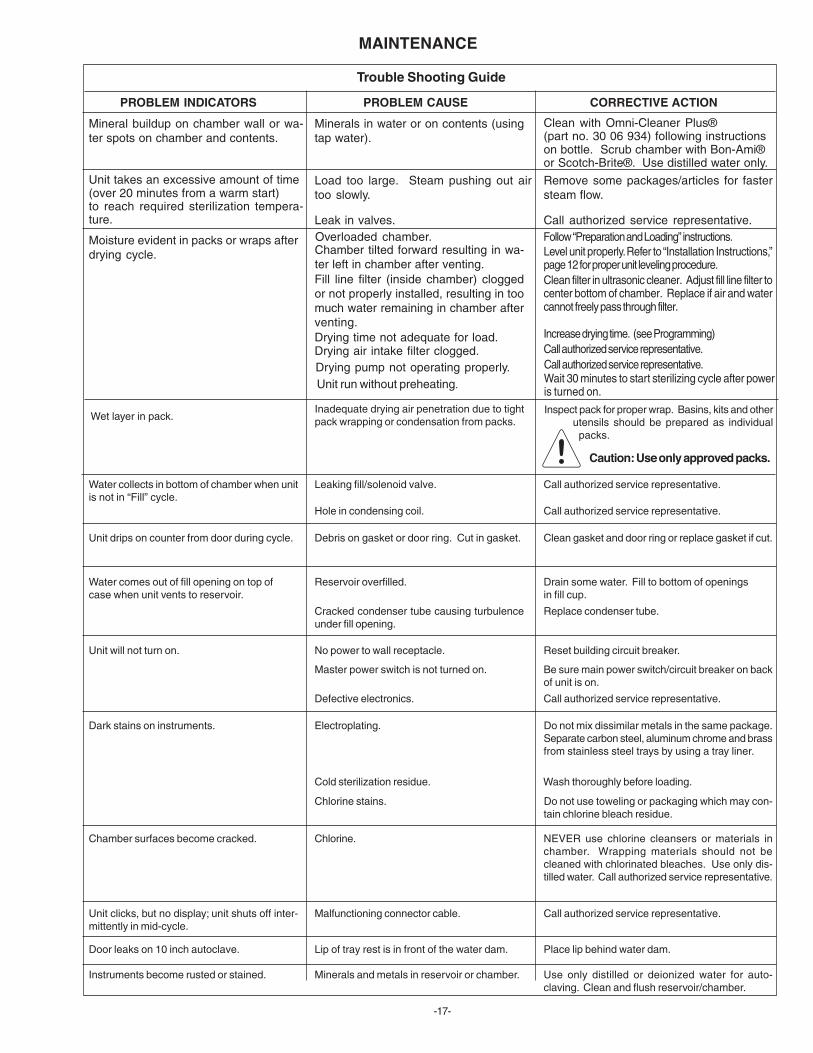
PROBLEM INDICATORS PROBLEM CAUSE CORRECTIVE ACTION
Clean with Omni-Cleaner Plus®(part no. 30 06 934) following instructionson bottle. Scrub chamber with Bon-Ami®or Scotch-Brite®. Use distilled water only.Remove some packages/articles for fastersteam flow.
Call authorized service representative.Follow “Preparation and Loading” instructions.Level unit properly. Refer to “Installation Instructions,”page 12 for proper unit leveling procedure.Clean filter in ultrasonic cleaner. Adjust fill line filter tocenter bottom of chamber. Replace if air and watercannot freely pass through filter.
Clean gasket and door ring or replace gasket if cut.
Call authorized service representative.
Call authorized service representative.
Call authorized service representative.
Drain some water. Fill to bottom of openingsin fill cup.
Replace condenser tube.
Reset building circuit breaker.
Be sure main power switch/circuit breaker on backof unit is on.
Minerals in water or on contents (usingtap water).
Mineral buildup on chamber wall or wa-ter spots on chamber and contents.
Load too large. Steam pushing out airtoo slowly.
Unit takes an excessive amount of time(over 20 minutes from a warm start)to reach required sterilization tempera-ture. Leak in valves.
Moisture evident in packs or wraps afterdrying cycle.
Overloaded chamber.Chamber tilted forward resulting in wa-ter left in chamber after venting.Fill line filter (inside chamber) cloggedor not properly installed, resulting in toomuch water remaining in chamber afterventing.
Water collects in bottom of chamber when unitis not in “Fill” cycle.
Leaking fill/solenoid valve.
Unit drips on counter from door during cycle.
Hole in condensing coil.
Debris on gasket or door ring. Cut in gasket.
Water comes out of fill opening on top ofcase when unit vents to reservoir.
Reservoir overfilled.
Cracked condenser tube causing turbulenceunder fill opening.
No power to wall receptacle.
Master power switch is not turned on.
Unit will not turn on.
Call authorized service representative.Defective electronics.
Dark stains on instruments. Electroplating. Do not mix dissimilar metals in the same package.Separate carbon steel, aluminum chrome and brassfrom stainless steel trays by using a tray liner.
Chlorine stains. Do not use toweling or packaging which may con-tain chlorine bleach residue.
Chamber surfaces become cracked. Chlorine. NEVER use chlorine cleansers or materials inchamber. Wrapping materials should not becleaned with chlorinated bleaches. Use only dis-tilled water. Call authorized service representative.
Unit clicks, but no display; unit shuts off inter-mittently in mid-cycle.
Door leaks on 10 inch autoclave.
Instruments become rusted or stained.
Malfunctioning connector cable.
Lip of tray rest is in front of the water dam.
Minerals and metals in reservoir or chamber.
Call authorized service representative.
Place lip behind water dam.
Use only distilled or deionized water for auto-claving. Clean and flush reservoir/chamber.
Drying time not adequate for load.Call authorized service representative.
Cold sterilization residue. Wash thoroughly before loading.
Increase drying time. (see Programming)
Inadequate drying air penetration due to tightpack wrapping or condensation from packs.Wet layer in pack.
Drying air intake filter clogged.Drying pump not operating properly.
Wait 30 minutes to start sterilizing cycle after poweris turned on.
Unit run without preheating.
Trouble Shooting Guide
Caution: Use only approved packs.
Inspect pack for proper wrap. Basins, kits and otherutensils should be prepared as individualpacks.

-18-
MAINTENANCETrouble Shooting Guide
PROBLEM INDICATORS PROBLEM CAUSE CORRECTIVE ACTION
Reduce load weight or check if load is packed prop-erly.
Check bioligical indicator instructions to make sureindicator is for a gravity type sterilizer. Check thatindicator is correct; one for cycle times and tem-peratures being run. If necessary, contact your bio-logical indicator representative.
Insuffcient steam penetration.
Wrong type of biological indicator for thissterilizer, wrong cycle used or biologicalindicator has expired.
Positive biological indicator
WARNING: Do not use instruments if unit fails to complete cycle.

-19-
Fill/vent solenoid
Dump solenoid
Bellows solenoid
Steam sensor
Surface sensor
Battery
Pressure trans-ducer
Line voltage
OPERATIONALFUNCTIONCHECKED
Solenoid operation andelectrical continuity.
Solenoid operation andelectrical continuity.
Solenoid operation andelectrical continuity.
Electrical continuity andparameter check.
Electrical continuity.
Parameter memory forspecials mode (e.g.,clock settings).
Nominal operatingparameter.
Adequate voltage.
CHECKDISPLAY
COMPONENTSCHECKED
MAINTENANCE
Self-Diagnostic CheckAutomatic CheckThe autoclave automatically performs a diagnostic self-check on nine key components for operational continuityeach time the main power switch (toggle switch locatedat rear of unit) is turned on.
An additional check may be made by the followingprocedure:
Operational Check
Depress “Power On” switch and “Clear/Start” switch at the same time. The autoclave beeps once,signaling the beginning of the self-diagnostic procedure.
During the first four seconds, check that all displaysegments illuminate. If segments do not illuminate, callan authorized service representative. This problem cangive the operator incorrect information if not repaired.
After self-diagnostics, the unit returns to stand-by. Thelower window displays any error found during theOperational or Automatic self-diagnostic check proce-dure. See table at left for explanation of display.
Call an authorized service representative if an unsatisfac-tory check is indicated.

-20-
MAINTENANCE
Operating AlarmsEight alarms can occur during a sterilization cycle. All alarms are indicated by a “beeping” sound for one minute (or until“Clear/Start” is depressed) and an alarm display in the lower display window. The alarm display will remain visible until theproblem is corrected or until the “Clear/Start” button is depressed.
DISPLAY ACTIONCAUSE
Chamber door not fully closed.
Problem with door switch.
Not enough water in chamber.
Chamber has boiled dry.
Not enough water in chamber.
Leak in gasket.
Failure to fill properly. Failure to seal againstpressure.
Chamber overloaded.
More than 10-minute lapse during air bleedingprocess.
Door opened during temperature rise.
More than a 3-minute lapse during sterilizationcountdown.
Low water indicator.
Defective pressure-sensing circuit.
Overpressure in the system.
Temperature is less thant 10° C. Defectivesteam sensor.
Steam temperature too high.
Shut door properly.
Check door switch (see Maintenance, pg. 24).
Inspect for clogged reservoir and chamber filter. Clean orreplace filter as necessary.
See that there is sufficent water in reservoir. Clear unit.Restart cycle. If problem recurs, turn off “Power” switch andcall an authorized service representative.
Inspect for clogged reservoir and chamber filter. Clean orreplace filter as necessary.
Check door gasket and chamber sealing surface for debrisor cuts and clean or replace as needed.
Turn off “Power” switch and call an authorized service rep-resentative.
Check chamber for proper loading and remove some pack-ages/articles which may be impeding proper steam circula-tion.
Check chamber for proper loading and remove some pack-ages/articles which may be impeding proper steam circula-tion.
Shut door properly.
Clear unit. Restart cycle. If problem recurs, turn off “Power”switch and call an authorized service representative.Add distilled water to reservoir between cycles.
Turn off “Power” switch and call an authorized service rep-resentative.
Clear unit. Restart cycle. If problem recurs, turn off“Power” switch and call an authorized service representa-tive.
Let unit warm up before operating. Turn OFF power switchand call an authorized service technician.
Turn off “Power” switch and call an authorized service rep-resentative.

-21-
OPTIONS
Tray Clip Installation for Additional Trays
To install additional European trays into 8” autoclave, firstinsert tray rack (A), then slide clips over middle (B) and top Ctray rest rods and let the outside edges (D) of the lips restagainst the wall of the autoclave. Tray rest will then hold fouropen trays.
To install additional trays into 10” autoclave, first snap upper(E) and middle F pair of clips onto rods. Bottom edge of topclip should wrap over middle rod, next to the bottom edge ofthe top clip. Insert tray rack into autoclave. Finally, insertbottom (short) set of clips (G) onto bottom rods so that theyline up with the top clip, letting the outside edge (H) restagainst the wall of the autoclave. Tray rest will then hold sixopen trays.
Time/Temperature RecorderThe 120V Time/Temperature Recorder User Manual isP/N 15 26 818.
The Time/Temperature Recorder works in conjuction with the 8”and 10” model autoclaves to provide complete sterilizationrecords of temperature, pressure and time of sterilizationcycles.Refer to autoclave Time/Temperature Recorder Manual forcomplete installation and operating instructions.
HU-Friedy/European Cassette Rack(P/N 024338) for 10” autoclave.IV. European Cassette Rack (P/N 023554)for 8” autoclave.
DELTA Q 8”
DELTA Q 10”

-22-
INSTALLATION AND SERVICING CHECKLIST
Verify the following after installation or servicing of the unit if applicable:
All manuals are present.
All labels are present and legible.
No mechanical damage on new installations.
The chamber filter is positioned and touches the bottom center of the chamber.
The unit is connected to the correct power source.
The unit is setting on a level surface.
The air tube inside the chamber is properly installed.
The reservoir is full of distilled water only.
When the clear/start switch is pressed the display comes on.
The door latch opens and closes properly.
When depressing the mode selection switch, the unit changes programs.
While running the unit there is no water or steam leaking from the chamber or tubing.
If optional printer is connected and after starting a cycle, the printer starts to print periodically through the cycle.
The unit passes a Hi-Pot test.
All terminals are connected securely.
The filters are new.
The unit passes a ground continuity test.
The internal wiring is in good shape and not frayed.

-23-
NOTES

We reserve the right to make any alterations which may be due to technical improvements.
Pelton & CraneP.O. Box 7800Charlotte, NC 28241-7800USA
©2008, Pelton & Crane
P/N 053169 Rev. 0


![Ohio fi.gricultural ExpErimEnt Statim]](https://img.pdfslide.net/doc/110x75/6172b2231b7c9329b74a1410/ohio-figricultural-experiment-statim.jpg)