Embed Size (px)
Citation preview

13th World Conference on Earthquake Engineering Vancouver, B.C., Canada
August 1-6, 2004 Paper No. 4006
USE OF “CONTROLLED ROCKING” IN THE SEISMIC DESIGN OF BRIDGES
Alessandro PALERMO1, Stefano PAMPANIN2, Gian Michele CALVI3
SUMMARY The development of alternative solutions for precast concrete buildings based on jointed ductile connections has introduced an innovative concept in the seismic design of frame and shear wall systems. In this contribution, the feasibility and efficiency of the application to bridge piers and systems of hybrid solutions, where self-centering and energy dissipating properties are adequately combined to achieve the target maximum displacement with negligible residual deformations, are investigated. Comparison of the seismic response of hybrid (or controlled rocking) solutions and traditional monolithic systems is carried out through push-pull and non-linear time-history analyses on both single and multi-degree of freedom bridge systems. Critical discussion on the enhanced performance of hybrid solutions is provided.
INTRODUCTION Traditional seismic design of ductile reinforced concrete structures implies the non-linear behavior of the system to be accommodated through the formations of flexural plastic hinges in structural elements (i.e. top and/or bottom of piers in the case of bridge systems). As a consequence of the inelastic structural response, a significant level of damage is thus expected and has so far been accepted. Recent developments (through numerical and experimental investigations) in the design of precast reinforced concrete buildings, under the U.S. PRESSS (PREcast Seismic Structural System Structural), coordinated by the University of California, San Diego (Priestley [1], Priestley et al. [2]) have resulted in the definition of innovative typologies of “jointed ductile systems”, for both frame and wall systems, as alternative to equivalent “cast-in-place” or “emulation of cast-in-place” solutions. Pure precast elements are connected though unbonded post-tensioning techniques; the inelastic demand is accommodated within the connection itself (beam-column, column-foundation, wall-foundation critical interface) where a “controlled rocking” motion occurs with opening and closing of existing gap; as a consequence, a very limited level of damage is expected in the structural elements which are maintained in the elastic range. A particularly promising efficiency and high flexibility (Stanton et al. [3]) has been shown by the hybrid systems, i.e. systems with “controlled rocking”, where unbonded post-tensioning tendons/bars (plus axial load contribution in wall systems) with self-centering properties are adequately combined with 1 PhD Candidate, Technical University of Milan, Italy. Email: [email protected] 2 Senior Lecturer, University of Canterbury, New Zealand. Email: : [email protected] 3 Full Professor, University of Pavia, Italy. Email: [email protected]
longitudinal mild steel or additional dissipation devices, which can provide an appreciable energy dissipation (Figure 1).
Post-tensioned (PT) unbonded tendons
Energy dissipation devices
a) b)
Figure 1 Hybrid Systems developed in the PRESSS program for frame and shear wall systems Priestley et al. [2]; b) Courtesy of Mrs. S. Nakaki (picture)
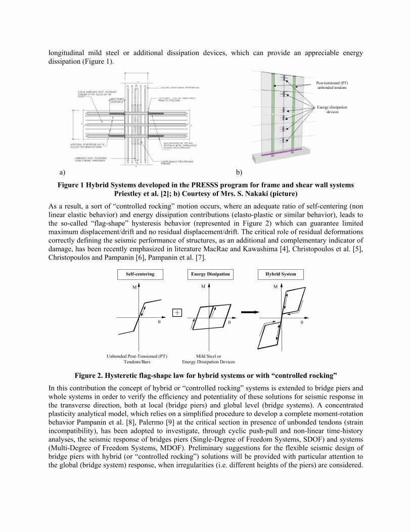
As a result, a sort of “controlled rocking” motion occurs, where an adequate ratio of self-centering (non linear elastic behavior) and energy dissipation contributions (elasto-plastic or similar behavior), leads to the so-called “flag-shape” hysteresis behavior (represented in Figure 2) which can guarantee limited maximum displacement/drift and no residual displacement/drift. The critical role of residual deformations correctly defining the seismic performance of structures, as an additional and complementary indicator of damage, has been recently emphasized in literature MacRae and Kawashima [4], Christopoulos et al. [5], Christopoulos and Pampanin [6], Pampanin et al. [7].
M
θ
M
θ
M
θ
Self-centering Energy Dissipation Hybrid System
Unbonded Post-Tensioned (PT) Tendons/Bars
Mild Steel orEnergy Dissipation Devices
Figure 2. Hysteretic flag-shape law for hybrid systems or with “controlled rocking”
In this contribution the concept of hybrid or “controlled rocking” systems is extended to bridge piers and whole systems in order to verify the efficiency and potentiality of these solutions for seismic response in the transverse direction, both at local (bridge piers) and global level (bridge systems). A concentrated plasticity analytical model, which relies on a simplified procedure to develop a complete moment-rotation behavior Pampanin et al. [8], Palermo [9] at the critical section in presence of unbonded tendons (strain incompatibility), has been adopted to investigate, through cyclic push-pull and non-linear time-history analyses, the seismic response of bridges piers (Single-Degree of Freedom Systems, SDOF) and systems (Multi-Degree of Freedom Systems, MDOF). Preliminary suggestions for the flexible seismic design of bridge piers with hybrid (or “controlled rocking”) solutions will be provided with particular attention to the global (bridge system) response, when irregularities (i.e. different heights of the piers) are considered.
Comparisons with the performance of traditional cast-in-situ reinforced concrete solutions will be critically discussed.
EXTENSION OF HYBRID OR “CONTROLLED ROCKING” CONCEPT TO BRIDGE PIERS
As mentioned before, the hybrid or “controlled rocking” connections, originally proposed for precast concrete frames, and successively extended to steel frames (Christopoulos et al. [10]), have found immediate and efficient applicability to wall systems (Priestley [2], Kurama et al. [11], Holden et al. [12]). In these vertical systems (walls, columns, piers), significant self-centering contribution is provided by the axial load, in addition to that given by the post-tensioned bars/tendons, whose number and initial prestress level can thus be reduced in the design phase. The first applications and extensions of hybrid concept or “controlled rocking” to bridge piers, proposed by Mander and Chen [13] at University of Buffalo, were based on experimental and numerical investigations. In particular, within the experimental investigations, shake-table tests on bridge piers, with unbonded post-tensioned cables combined with viscous dissipation devices at top/bottom pier sections were carried out. On the modeling side, a simplified analysis assuming a rigid-body behavior of bridge pier (Housner [14]), was considered. Other analytical-experimental investigations on precast segmented piers with unbonded post-tension cables have been performed at University of California, San Diego (Hewes and Priestley [15]). No supplemental damping or additional energy dissipation devices were added to the pier system: in the experimental investigations quasi static push-pull analysis were carried-our, while on the analytical side a simplified but accurate modeling procedure, developed as part of the U.S. PRESSS Program (Pampanin [8]), considering pier elements as deformable bodies, was adopted. After the observed extensive damages, beyond the reparability limit, on bridge piers due to the Kobe earthquake (1995), several studies have been promoted in Japan in order to improve the structural response and limit the damage level. As reported in Kawashima [16], the static residual displacement is assumed as one of the fundamental parameters to define the damage level of bridge piers; in particular the Japanese Seismic Code imposes a check on the expected residual (permanent) drift. In order to limit residual displacement of bridge piers alternative solutions, which rely on the use of post-tensioned bars or tendons (bonded or partially unbonded during the casting) have been proposed (Zatar and Mutsuyoshi [17], Kawashima [18], Ikeda et al. [19]). Consequently the hysteretic behavior has been improved, adding self-centering capacity without however significantly reducing the damage level of the pier due to the adoption of a traditional monolithic connection without rocking motion at the pier/foundation and/or pier/deck interface section. With the present work, referring to the previous results on single bridge piers, indications on sectional design, outlining principal parameters affecting the hysteretic behavior of these connections, will be carried out. Particular attention will be given to the global response of different bridges with “controlled rocking solutions”. The effects on the system response, when varying the design parameters in the critical section or when considering (restraint) alternative dispositions of pier heights along the longitudinal axis, will also be investigated.
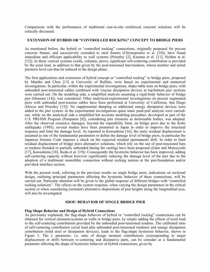
SDOF: BEHAVIOR OF SINGLE BRIDGE PIER Flag Shape Behavior and Design of Hybrid Connections As previously explained, the flag-shape behavior of hybrid or “controlled rocking” connections can be obtained for vertical elements/systems as walls or bridge piers, by simply adding the effects of axial load to the self-centering contribution provided by the unbonded post-tensioned tendons. The calibrated ratio of self-centering contribution (axial load plus unbonded post-tensioned tendons) and energy dissipation contribution (mild steel or dissipation devices), leads to the flag-shape hysteresis behavior, shown in Figure 3. The λ parameter, i.e. ratio of design moment contributions (corresponding to target displacement or drift) between re-centering and dissipative parts, can be consider as a fundamental parameter affecting the shape of hysteretic behavior of hybrid connections, given by
pt N
s
M MM
λ+
=
where Mpt, MN represent, moment capacities due to post-tension cables/tendons and axial load, while Ms the moment capacity due to mild steel (or dissipative devices), respectively. Section moment capacities are evaluated around the centroid of the total compression force.
-20000
-10000
0
10000
20000
-0,02 -0,01 0,00 0,01 0,02Drift
Mom
ent [
kN m
]
λ = 0,5
λ = 1 λ = 1,5
λ = 2
Figure 3 Moment - rotation varying λ parameter
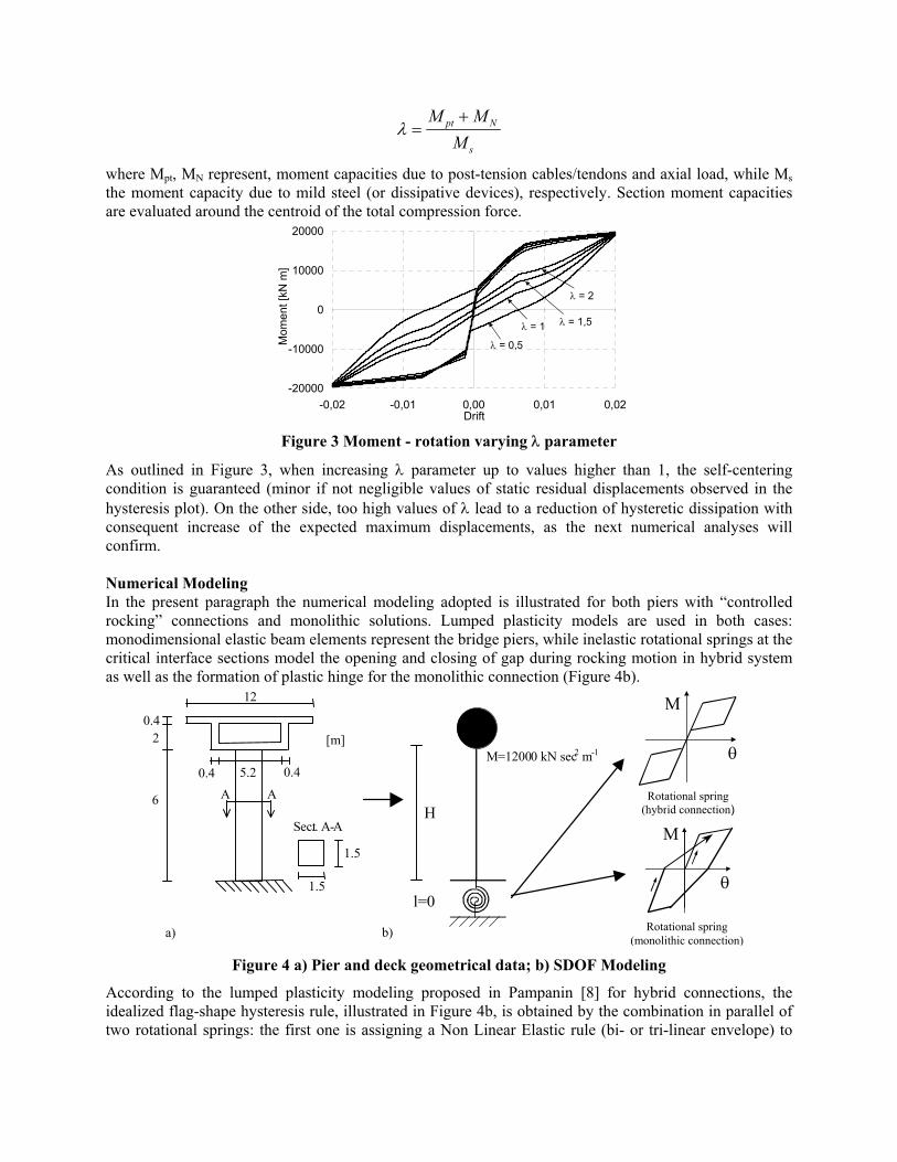
As outlined in Figure 3, when increasing λ parameter up to values higher than 1, the self-centering condition is guaranteed (minor if not negligible values of static residual displacements observed in the hysteresis plot). On the other side, too high values of λ lead to a reduction of hysteretic dissipation with consequent increase of the expected maximum displacements, as the next numerical analyses will confirm. Numerical Modeling In the present paragraph the numerical modeling adopted is illustrated for both piers with “controlled rocking” connections and monolithic solutions. Lumped plasticity models are used in both cases: monodimensional elastic beam elements represent the bridge piers, while inelastic rotational springs at the critical interface sections model the opening and closing of gap during rocking motion in hybrid system as well as the formation of plastic hinge for the monolithic connection (Figure 4b).
Rotational spring (monolithic connection)
M
θ
M
θ
Rotational spring (hybrid connection) H
l=0
M=12000 kN sec2 m-1
6
0.4 2
0.4 0.4 5.2
1 2
A A
1.5
1.5 S ect .. A - A
[m]
a) b) Figure 4 a) Pier and deck geometrical data; b) SDOF Modeling
According to the lumped plasticity modeling proposed in Pampanin [8] for hybrid connections, the idealized flag-shape hysteresis rule, illustrated in Figure 4b, is obtained by the combination in parallel of two rotational springs: the first one is assigning a Non Linear Elastic rule (bi- or tri-linear envelope) to
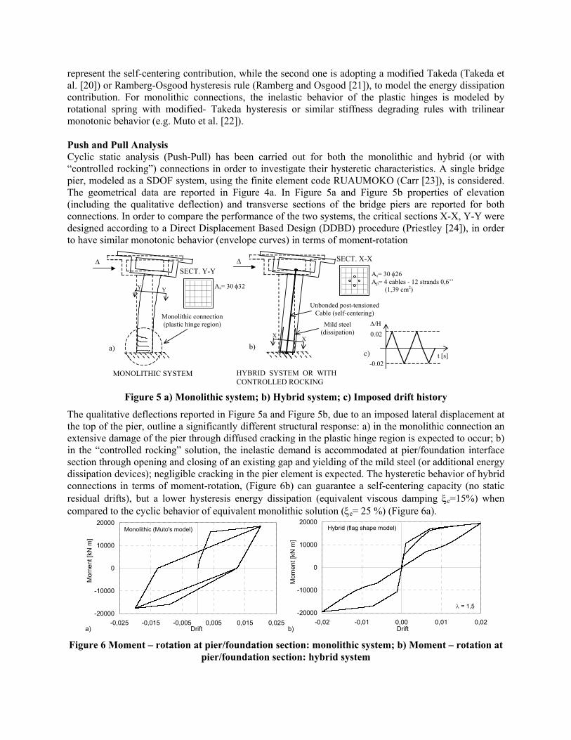
represent the self-centering contribution, while the second one is adopting a modified Takeda (Takeda et al. [20]) or Ramberg-Osgood hysteresis rule (Ramberg and Osgood [21]), to model the energy dissipation contribution. For monolithic connections, the inelastic behavior of the plastic hinges is modeled by rotational spring with modified- Takeda hysteresis or similar stiffness degrading rules with trilinear monotonic behavior (e.g. Muto et al. [22]). Push and Pull Analysis Cyclic static analysis (Push-Pull) has been carried out for both the monolithic and hybrid (or with “controlled rocking”) connections in order to investigate their hysteretic characteristics. A single bridge pier, modeled as a SDOF system, using the finite element code RUAUMOKO (Carr [23]), is considered. The geometrical data are reported in Figure 4a. In Figure 5a and Figure 5b properties of elevation (including the qualitative deflection) and transverse sections of the bridge piers are reported for both connections. In order to compare the performance of the two systems, the critical sections X-X, Y-Y were designed according to a Direct Displacement Based Design (DDBD) procedure (Priestley [24]), in order to have similar monotonic behavior (envelope curves) in terms of moment-rotation
MONOLITHIC SYSTEM
∆
Y Y
Monolithic connection (plastic hinge region)
a)
∆
Unbonded post-tensioned Cable (self-centering)
Mild steel (dissipation) X X
HYBRID SYSTEM OR WITHCONTROLLED ROCKING
b) c)
SECT. Y-Y
As= 30 φ32
SECT. X-X
As= 30 φ26 Ap= 4 cables - 12 strands 0,6’’ (1,39 cm2)
t [s]
∆/H 0.02
-0.02
Figure 5 a) Monolithic system; b) Hybrid system; c) Imposed drift history
The qualitative deflections reported in Figure 5a and Figure 5b, due to an imposed lateral displacement at the top of the pier, outline a significantly different structural response: a) in the monolithic connection an extensive damage of the pier through diffused cracking in the plastic hinge region is expected to occur; b) in the “controlled rocking” solution, the inelastic demand is accommodated at pier/foundation interface section through opening and closing of an existing gap and yielding of the mild steel (or additional energy dissipation devices); negligible cracking in the pier element is expected. The hysteretic behavior of hybrid connections in terms of moment-rotation, (Figure 6b) can guarantee a self-centering capacity (no static residual drifts), but a lower hysteresis energy dissipation (equivalent viscous damping ξe=15%) when compared to the cyclic behavior of equivalent monolithic solution (ξe= 25 %) (Figure 6a).
-20000
-10000
0
10000
20000
-0,025 -0,015 -0,005 0,005 0,015 0,025Drift
Mom
ent [
kN m
]
Monolithic (Muto's model)
a)
-20000
-10000
0
10000
20000
-0,02 -0,01 0,00 0,01 0,02Drift
Mom
ent [
kN m
]
λ = 1,5
Hybrid (flag shape model)
b) Figure 6 Moment – rotation at pier/foundation section: monolithic system; b) Moment – rotation at
pier/foundation section: hybrid system
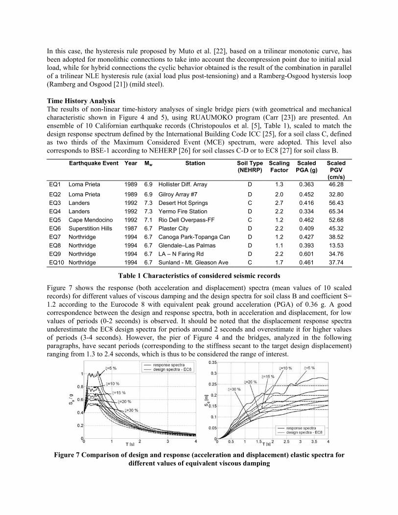
In this case, the hysteresis rule proposed by Muto et al. [22], based on a trilinear monotonic curve, has been adopted for monolithic connections to take into account the decompression point due to initial axial load, while for hybrid connections the cyclic behavior obtained is the result of the combination in parallel of a trilinear NLE hysteresis rule (axial load plus post-tensioning) and a Ramberg-Osgood hystersis loop (Ramberg and Osgood [21]) (mild steel). Time History Analysis The results of non-linear time-history analyses of single bridge piers (with geometrical and mechanical characteristic shown in Figure 4 and 5), using RUAUMOKO program (Carr [23]) are presented. An ensemble of 10 Californian earthquake records (Christopoulos et al. [5], Table 1), scaled to match the design response spectrum defined by the International Building Code ICC [25], for a soil class C, defined as two thirds of the Maximum Considered Event (MCE) spectrum, were adopted. This level also corresponds to BSE-1 according to NEHERP [26] for soil classes C-D or to EC8 [27] for soil class B.
Earthquake Event Year Mw Station Soil Type(NEHRP)
Scaling Factor
Scaled PGA (g)
Scaled PGV
(cm/s) EQ1 Loma Prieta 1989 6.9 Hollister Diff. Array D 1.3 0.363 46.28
EQ2 Loma Prieta 1989 6.9 Gilroy Array #7 D 2.0 0.452 32.80 EQ3 Landers 1992 7.3 Desert Hot Springs C 2.7 0.416 56.43 EQ4 Landers 1992 7.3 Yermo Fire Station D 2.2 0.334 65.34 EQ5 Cape Mendocino 1992 7.1 Rio Dell Overpass-FF C 1.2 0.462 52.68 EQ6 Superstition Hills 1987 6.7 Plaster City D 2.2 0.409 45.32 EQ7 Northridge 1994 6.7 Canoga Park-Topanga Can D 1.2 0.427 38.52 EQ8 Northridge 1994 6.7 Glendale–Las Palmas D 1.1 0.393 13.53 EQ9 Northridge 1994 6.7 LA – N Faring Rd D 2.2 0.601 34.76 EQ10 Northridge 1994 6.7 Sunland - Mt. Gleason Ave C 1.7 0.461 37.74
Table 1 Characteristics of considered seismic records
Figure 7 shows the response (both acceleration and displacement) spectra (mean values of 10 scaled records) for different values of viscous damping and the design spectra for soil class B and coefficient S= 1.2 according to the Eurocode 8 with equivalent peak ground acceleration (PGA) of 0.36 g. A good correspondence between the design and response spectra, both in acceleration and displacement, for low values of periods (0-2 seconds) is observed. It should be noted that the displacement response spectra underestimate the EC8 design spectra for periods around 2 seconds and overestimate it for higher values of periods (3-4 seconds). However, the pier of Figure 4 and the bridges, analyzed in the following paragraphs, have secant periods (corresponding to the stiffness secant to the target design displacement) ranging from 1.3 to 2.4 seconds, which is thus to be considered the range of interest.
Figure 7 Comparison of design and response (acceleration and displacement) elastic spectra for
different values of equivalent viscous damping
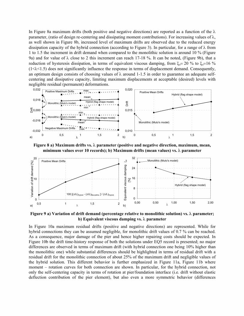
In Figure 8a maximum drifts (both positive and negative directions) are reported as a function of the λ parameter, (ratio of design re-centering and dissipating moment contributions). For increasing values of λ, as well shown in Figure 8b, increased level of maximum drifts are observed due to the reduced energy dissipation capacity of the hybrid connection (according to Figure 3). In particular, for a range of λ from 1 to 1.5 the increment in drift demand when compared to the monolithic solution is around 10 % (Figure 9a) and for value of λ close to 2 this increment can reach 17-18 %. It can be noted, (Figure 9b), that a reduction of hysteresis dissipation, in terms of equivalent viscous damping, from ξe= 20 % to ξe=16 % (1<λ<1.5) does not significantly influence the response in terms of displacement demand. Consequently, an optimum design consists of choosing values of λ around 1-1.5 in order to guarantee an adequate self-centering and dissipative capacity, limiting maximum displacements at acceptable (desired) levels with negligible residual (permanent) deformations.
-0,032
-0,016
0,000
0,016
0,032
0 0,5 1 1,5 2
Drif
t
λ
Positive Maximum Drifts
Negative Maximum Drifts
Hybrid (flag shape model)
Monolithic (Muto's model) Hybrid (flag shape model)
Monolithic (Muto's model)
a)
max
min
mean
max
mean
min
0,010
0,015
0,020
0 0,5 1 1,5 2
Drif
t
λ
Positive Mean Drifts
Monolithic (Muto's model)
Hybrid (flag shape model)
b)
Figure 8 a) Maximum drifts vs. λ parameter (positive and negative direction, maximum, mean, minimum values over 10 records); b) Maximum drifts (mean values) vs. λ parameter
0
10
20
0,5 1 1,5 2
Var
iatio
n of
drif
t dem
and
[%]
λ
Positive Mean Drifts
100 [(∆/L)Hybrid - (∆/L)Monolithic ] / (∆/L)Hybrid
a)
0
8
16
24
32
0,00 0,50 1,00 1,50 2,00λ
Equ
ival
ent v
isco
us d
ampi
ng
ξ e
[%]
Hybrid (flag shape model)
Monolithic (Muto's model)
b) Figure 9 a) Variation of drift demand (percentage relative to monolithic solution) vs. λ parameter;
b) Equivalent viscous damping vs. λ parameter
In Figure 10a maximum residual drifts (positive and negative directions) are represented. While for hybrid connections they can be assumed negligible, for monolithic drift values of 0.7 % can be reached. As a consequence, major damage of the pier and hence higher repairing costs should be expected. In Figure 10b the drift time-history response of both the solutions under EQ5 record is presented; no major differences are observed in terms of maximum drift (with hybrid connection one being 10% higher than the monolithic one) while substantial differences should be highlighted in terms of residual drift with a residual drift for the monolithic connection of about 25% of the maximum drift and negligible values of the hybrid solution. This different behavior is further emphasized in Figure 11a, Figure 11b where moment – rotation curves for both connection are shown. In particular, for the hybrid connection, not only the self-centering capacity in terms of rotation at pier/foundation interface (i.e. drift without elastic deflection contribution of the pier element), but also even a more symmetric behavior (differences

between maximum rotation in the positive and negative directions), when compared to the monolithic solution, is outlined.
-0,008
-0,004
0,000
0,004
0,008
0 0,5 1 1,5 2
Drif
t
Positive Residual Drifts
Negative Residual Drifts
λ
Hybrid (flag shape model)Monolithic (Muto's model)
a)
-0,025
-0,015
-0,005
0,005
0,015
0,025
0 10 20 30 40Time [s]
Drif
t
Monolithic Connection
Hybrid Connection (λ=1,5)
Residual drift
b) Figure 10 a) Residual drifts (positive and negative medium values of 10 seismic events) vs. λ
parameter; b) Drift time-history (EQ5 record)
-20000
-10000
0
10000
20000
-0,020 -0,010 0,000 0,010 0,020 0,030Rotation [rad]
Mom
ent [
kN m
]
Residual rotation id
a)
-20000
-10000
0
10000
20000
-0,02 -0,01 0,00 0,01 0,02 0,03Rotation [rad]
Mom
ent [
kN m
]
Residual rotation id λ = 1,5
b) Figure 11 a) Moment –rotation at pier/foundation section: monolithic system; b) Moment – rotation
at pier/foundation section: hybrid system
TRANSVERSE SEISMIC RESPONSE OF FRAME-BRIDGES WITH HYBRID SOLUTION OR
“CONTROLLED ROCKING” Numerical Modeling In the following paragraphs the seismic (transverse) response of bridges is investigated though push-pull cyclic and non-linear time history analyses. A three-dimensional modeling with elastic beam elements and inelastic rotational springs is adopted. The rotational springs are located only at pier/foundation interface sections to simulate, respectively, the opening and closing of the gap during the rocking motion and consequent yielding of mild steel for the hybrid connections, as well as the formation of plastic hinge for the monolithic solutions. The same hysteresis rules for the rotational springs, as used for the analyses on SDOF systems, are adopted. Deck and pier elements are assumed to have an elastic behavior. Push and Pull Analysis and Flexible Design of Bridge Piers In this paragraph the response of a bridge system with geometrical data represented in Figure 12, designed according to a DDBD approach (Priestley [24]) adequately modified for the scope (Palermo [9]) is investigated. A push-pull analysis is first carried out, by imposing a force distribution Fi(t) at the top of the piers, corresponding to an assumed deflection shape at the target displacement level. The response of three bridge systems (namely A,B,C) with “controlled rocking” connections are compared: same geometrical data but different mechanical properties are assumed for every bridge pier (i.e. different values of λ parameter as discussed in Figure 13a). The three different distributions of λ along the piers (shown in Figure 13) have been chosen in order to obtain the same mean value (1.5 in this case), so that
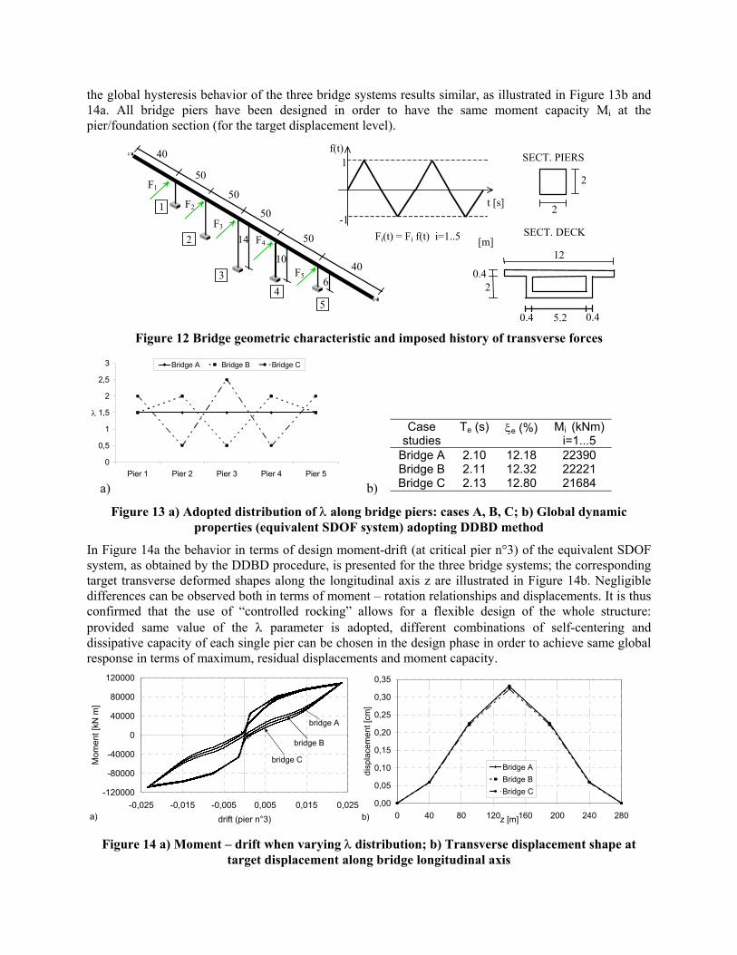
the global hysteresis behavior of the three bridge systems results similar, as illustrated in Figure 13b and 14a. All bridge piers have been designed in order to have the same moment capacity Mi at the pier/foundation section (for the target displacement level).
2
2
SECT. PIERS
0.4 2
0.4 0.45.2
12 [m]
SECT. DECK
t [s]
f(t) 1
-1 1 F2
F3
F4
F5
2
3 4
5
F1
Fi(t) = Fi f(t) i=1..5
40
50
40
50
50
50
14
10
6
Figure 12 Bridge geometric characteristic and imposed history of transverse forces
0
0,5
1
1,5
2
2,5
3
Pier 1 Pier 2 Pier 3 Pier 4 Pier 5
λ
Bridge A Bridge B Bridge C
a) b)
Figure 13 a) Adopted distribution of λ along bridge piers: cases A, B, C; b) Global dynamic properties (equivalent SDOF system) adopting DDBD method
In Figure 14a the behavior in terms of design moment-drift (at critical pier n°3) of the equivalent SDOF system, as obtained by the DDBD procedure, is presented for the three bridge systems; the corresponding target transverse deformed shapes along the longitudinal axis z are illustrated in Figure 14b. Negligible differences can be observed both in terms of moment – rotation relationships and displacements. It is thus confirmed that the use of “controlled rocking” allows for a flexible design of the whole structure: provided same value of the λ parameter is adopted, different combinations of self-centering and dissipative capacity of each single pier can be chosen in the design phase in order to achieve same global response in terms of maximum, residual displacements and moment capacity.
-120000
-80000
-40000
0
40000
80000
120000
-0,025 -0,015 -0,005 0,005 0,015 0,025drift (pier n°3)
Mom
ent [
kN m
]
bridge A
bridge B
bridge C
a)0,00
0,05
0,10
0,15
0,20
0,25
0,30
0,35
0 40 80 120 160 200 240 280z [m]
disp
lace
men
t [cm
]
Bridge ABridge BBridge C
b) Figure 14 a) Moment – drift when varying λ distribution; b) Transverse displacement shape at
target displacement along bridge longitudinal axis
Case studies
Te (s) ξe (%) Mi (kNm) i=1...5
Bridge A 2.10 12.18 22390 Bridge B 2.11 12.32 22221 Bridge C 2.13 12.80 21684
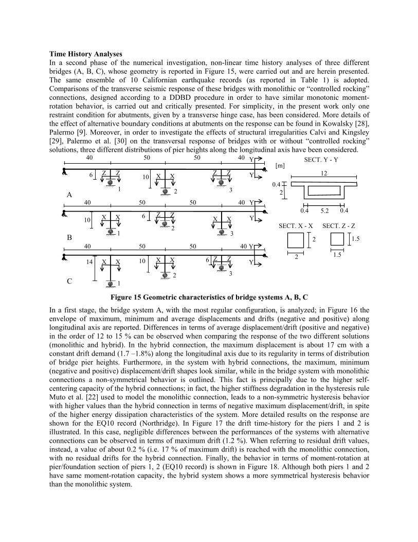
Time History Analyses In a second phase of the numerical investigation, non-linear time history analyses of three different bridges (A, B, C), whose geometry is reported in Figure 15, were carried out and are herein presented. The same ensemble of 10 Californian earthquake records (as reported in Table 1) is adopted. Comparisons of the transverse seismic response of these bridges with monolithic or “controlled rocking” connections, designed according to a DDBD procedure in order to have similar monotonic moment-rotation behavior, is carried out and critically presented. For simplicity, in the present work only one restraint condition for abutments, given by a transverse hinge case, has been considered. More details of the effect of alternative boundary conditions at abutments on the response can be found in Kowalsky [28], Palermo [9]. Moreover, in order to investigate the effects of structural irregularities Calvi and Kingsley [29], Palermo et al. [30] on the transversal response of bridges with or without “controlled rocking” solutions, three different distributions of pier heights along the longitudinal axis have been considered.
2
2
SECT. X - X
1.5
1.5
SECT. Z - Z
0.4 2
0.4 0.4 5.2
12 [m]
SECT. Y - Y
A
10
40 50 50 40
6
1 2 3
Z Z X X Z Z
Y
Y
B
40 50 50 40
6
21 3
Y
YZ Z X XX X 10
C
14
40 50 50 40
10
21
3
6
Y
YX XX X Z Z
Figure 15 Geometric characteristics of bridge systems A, B, C
In a first stage, the bridge system A, with the most regular configuration, is analyzed; in Figure 16 the envelope of maximum, minimum and average displacements and drifts (negative and positive) along longitudinal axis are reported. Differences in terms of average displacement/drift (positive and negative) in the order of 12 to 15 % can be observed when comparing the response of the two different solutions (monolithic and hybrid). In the hybrid connection, the maximum displacement is about 17 cm with a constant drift demand (1.7 –1.8%) along the longitudinal axis due to its regularity in terms of distribution of bridge pier heights. Furthermore, in the system with hybrid connections, the maximum, minimum (negative and positive) displacement/drift shapes look similar, while in the bridge system with monolithic connections a non-symmetrical behavior is outlined. This fact is principally due to the higher self-centering capacity of the hybrid connections; in fact, the higher stiffness degradation in the hysteresis rule Muto et al. [22] used to model the monolithic connection, leads to a non-symmetric hysteresis behavior with higher values than the hybrid connection in terms of negative maximum displacement/drift, in spite of the higher energy dissipation characteristics of the system. More detailed results on the response are shown for the EQ10 record (Northridge). In Figure 17 the drift time-history for the piers 1 and 2 is illustrated. In this case, negligible differences between the performances of the systems with alternative connections can be observed in terms of maximum drift (1.2 %). When referring to residual drift values, instead, a value of about 0.2 % (i.e. 17 % of maximum drift) is reached with the monolithic connection, with no residual drifts for the hybrid connection. Finally, the behavior in terms of moment-rotation at pier/foundation section of piers 1, 2 (EQ10 record) is shown in Figure 18. Although both piers 1 and 2 have same moment-rotation capacity, the hybrid system shows a more symmetrical hysteresis behavior than the monolithic system.

Figure 16 Bridge A: displacement and drifts demand (positive and negative maximum, minimum,
mean values of 10 records) along bridge longitudinal axis z
Figure 17 Bridge A: drift time-history of piers 1, 2 (EQ10 record)
Figure 18 Bridge A: moment-rotation at pier/foundation section of piers 1, 2 (EQ10 record)
When considering the response of the bridge system B, the non-regular distribution of pier heights comes into account. It can be noted that, when referring to maximum displacement demand, not substantial differences can be observed hence compared to the response of bridge system A. Consequently, due to the distribution of the pier height, a significant difference in terms of drift demand in the bridge piers has to be underlined, with the inelastic demand concentrated in the shortest pier in the center (average drift values of around 2.5%, Figure 19). Even in this case, the maximum, minimum and mean values of
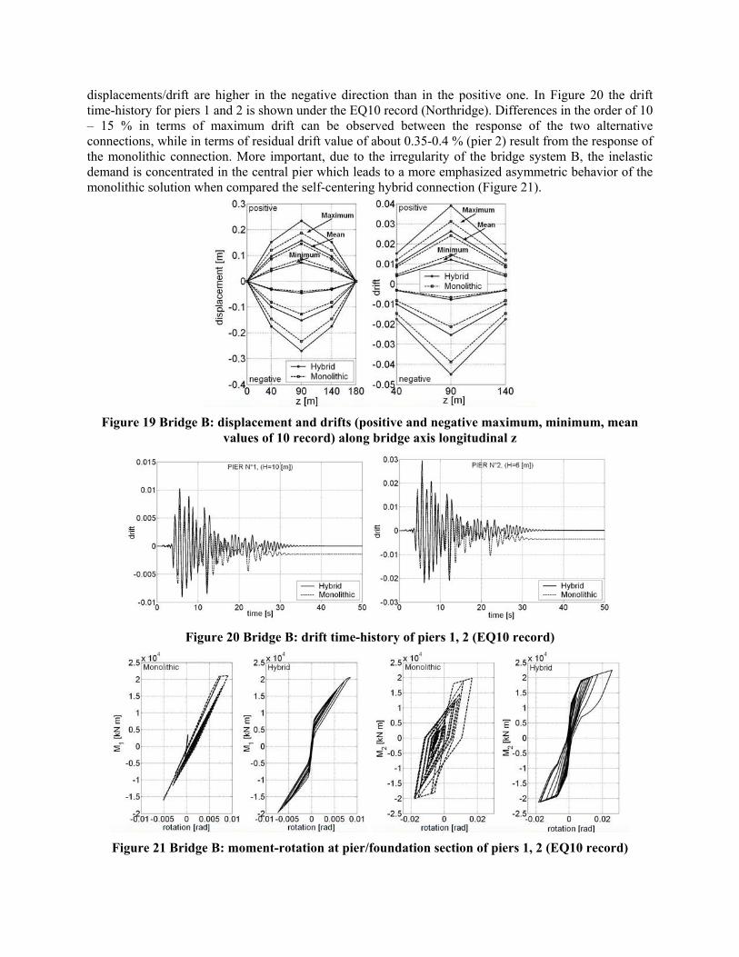
displacements/drift are higher in the negative direction than in the positive one. In Figure 20 the drift time-history for piers 1 and 2 is shown under the EQ10 record (Northridge). Differences in the order of 10 – 15 % in terms of maximum drift can be observed between the response of the two alternative connections, while in terms of residual drift value of about 0.35-0.4 % (pier 2) result from the response of the monolithic connection. More important, due to the irregularity of the bridge system B, the inelastic demand is concentrated in the central pier which leads to a more emphasized asymmetric behavior of the monolithic solution when compared the self-centering hybrid connection (Figure 21).
Figure 19 Bridge B: displacement and drifts (positive and negative maximum, minimum, mean
values of 10 record) along bridge axis longitudinal z
Figure 20 Bridge B: drift time-history of piers 1, 2 (EQ10 record)
Figure 21 Bridge B: moment-rotation at pier/foundation section of piers 1, 2 (EQ10 record)
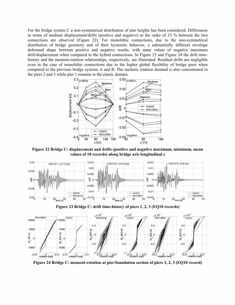
For the bridge system C a non-symmetrical distribution of pier heights has been considered. Differences in terms of medium displacement/drifts (positive and negative) in the order of 15 % between the two connections are observed (Figure 22). For monolithic connections, due to the non-symmetrical distribution of bridge geometry and of their hysteretic behavior, a substantially different envelope deformed shape between positive and negative results, with same values of negative maximum drift/displacement when compared to the hybrid connections. In Figure 23 and Figure 24 the drift time-history and the moment-rotation relationships, respectively, are illustrated. Residual drifts are negligible even in the case of monolithic connections due to the higher global flexibility of bridge piers when compared to the previous bridge systems A and B. The inelastic rotation demand is also concentrated in the piers 2 and 3 while pier 1 remains in the elastic domain.
Figure 22 Bridge C: displacement and drifts (positive and negative maximum, minimum, mean
values of 10 records) along bridge axis longitudinal z
Figure 23 Bridge C: drift time-history of piers 1, 2, 3 (EQ10 records)
Figure 24 Bridge C: moment-rotation at pier/foundation section of piers 1, 2, 3 (EQ10 record)

CONCLUSIONS The extension and application of hybrid or “controlled rocking” concept to bridge systems is an efficient and promising alternative solution to the traditional systems. The possibility of accommodating the inelastic demand at the critical section interface (pier/foundation and/or pier/deck) where a rocking motion takes place, clearly leads to a significant damage reduction in the pier element. As a consequence, repairing costs after seismic events would be limited to the replacement of the mild steel reinforcement (passing through the critical section) or of the sacrificial energy dissipating devices. For hybrid connections, the role of the λ parameter (ratio between self-centering and energy dissipation characteristics in terms of moment contributions) is fundamental for an adequate calibration of the seismic response of the system (flag-shape hysteresis), in order to limit maximum displacements at the top of the piers within desired (target) values and at the same time guarantee negligible residual (permanent) displacements. Non-linear time-history analyses on different bridge configurations (variation of regularity obtained through different distribution of pier heights) adopting monolithic or hybrid connections, have shown no substantial differences in terms of maximum displacements, with slightly higher values (10-15 %) for the less-dissipative hybrid systems. More important, negligible residual displacement results in the response of bridges with “controlled rocking” solutions, while values in order of 20% of the maximum pier drift/displacement should be expected and accepted when monolithic connections are adopting. The irregularity of the system seems also to emphasize the differences in terms of residual displacement more than those in terms of maximum displacements. More complete details on the sectional analysis and design approach, as well as on the parametric analyses with alternative deck stiffnesses and abutment restraint conditions are reported in Palermo [9].
REFERENCES 1. Priestley M J N. “The PRESSS Program – Current Status and Proposed Plans for Phase III”. PCI
Journal 1996, 41(2): 22-40. 2. Priestley M J N, Sritharan S, Conley J R, Pampanin S. “Preliminary Results and Conclusions from
the PRESSS Five-story Precast Concrete Test-building”, PCI Journal 1999, 44(6): 42-67. 3. Stanton J F, Stone W C, Cheok G S. “A Hybrid Reinforced Precast Frame for Seismic Regions”.
PCI Journal 1997, 42(2): 20-32. 4. MacRae G A, Kawashima K. “Post-Earthquake Residual Displacements of Bilinear Oscillators”.
Earthquake Engineering and Structural Dynamics 1997, 26: 701-716. 5. Christopoulos C, Pampanin S, Priestley M J N. “Performance-Based Seismic Response of Frame
Structures Including Residual Deformations. Part I: Single-Degree-of-Freedom Systems”. Journal of Earthquake Engineering 2003, 7 (1): 97-118.
6. Christopoulos C, Pampanin S. “Towards Performance-Based Design of MDOF Structures with Explicit Consideration on Residual Deformations” ISET Journal of Structural Engineering, Special Issue on “Performance-Based Seismic Design”, March 2004.
7. Pampanin S, Christopoulos C, Priestley M J N. “Performance-Based Seismic Response of Frame Structures Including Residual Deformations. Part II: Multi-Degree-of-Freedom Systems”. Journal of Earthquake Engineering 2003, 7 (1): 119-147.
8. Pampanin S, Priestley M J N, Sritharan S. “Analytical Modeling of the Seismic Behavior of Precast Concrete Frames Designed with Ductile Connections”. Journal of Earthquake Engineering (JEE) 2001, 5(3): 329-367, Imperial College Press.
9. Palermo A. “The Use of Controlled Rocking in the Seismic Design of Bridges”. Ph.D Dissertation. Technical University of Milan, 2004, under preparation.
10. Christopoulos C, Filiatrault A, Uang C-M, Folz B. “Post-tensioned Energy Dissipating Connections for Moment Resisting Steel Frames”. ASCE Journal of Structural Engineering, accepted for publication, 2001.
11. Kurama Y C, Sause R, Pessiki S, Lu L-W. “Seismic Response Evaluation of Unbonded Post-tensioned Precast Walls”. ACI Structural Journal 2002, 99(5): 641-651.
12. Holden T, Restrepo J, Mander J B. “Seismic Performance of Precast Reinforced and Prestressed Concrete Walls”. Journal of Structural Engineering 2003, 129(3): 277-424.
13. Mander J B, Chen C T. “Seismic Resistance of Bridge Piers Based on Damage Avoidance Design”. Technical Report NCEER-97-0014 (National Centre for Earthquake Engineering Research). State University of New York, Buffalo, December 10 1997.
14. Housner G W. “The Behaviour of Inverted Pendulum Structures during Earthquake”. Bullettin of Seismological Society of America 1963, 53(2): 403-417.
15. Hewes J T, Priestley M J N. “Experimental Testing of Unbonded Post-tensioned Precast Concrete Segmental Bridge Columns”. Proceedings of the 6th Caltrans Seismic Research Workshop Program, Radisson Hotel, Sacramento, California, June 12-13, Div. of Engineering Services, California Dept. of Transportation, Sacramento, 8 pages, 2001.
16. Kawashima K. “The 1996 Japanese Seismic Design Specifications of Highway Bridges and the Performance Based Design”. Proceedings, Seismic Design Methodologies for the Next Generation of Codes, June 24-27, Bled, Slovenia, Fajfar & Krawinkler (eds), Balkema, Rotterdam, 1997: 371-382.
17. Zatar W, Mutsuyoshi H. “Reduced Residual Displacements of Partially Prestressed Concrete Bridge Piers”. Proceedings of 12WCEE, 12th World Conference on Earthquake Engineering, Auckland, January 30-February 4, (1111) 1-8. (computer file), 2000.
18. Kawashima K. “Seismic Design of Concrete Bridges”. Proceedings of the 1st fib Congress. Osaka, October 13-19, 347-366, (computer file), 2002.
19. Ikeda S, Hirose S, Yamaguchi T, Nonaka S. “Seismic Performance of Concrete Piers Prestressed in the Critical Sections”. Proceedings of the 1st fib Congress. Osaka, October 13-19, 207-214, (computer file), 2002.
20. Takeda T, Sozen M A, Nielsen N N. “Reinforced Concrete Response to Simulated Earthquakes”. Journal of the Structural Division, Proceedings of American Society of Civil Engineers, 1970, 96(12): 2557-2573.
21 Ramberg W, Osgood W R. “Description of Stress-Strain Curves by Three Parameters”. National Advisory Committee on Aeronautics, Technical Note 902, 1943.
22. Muto K, Ohmori N, Sugano T, Miyashita T, Shimizu H. “Non-linear Analysis of Reinforced Concrete Buildings. Theory and Practice in Finite Element Structural Analysis”. Yamada, T. and Gallagher1973: 399-421, Tokyo, R.H. Eds. University of Tokyo Press.
23. Carr A. “RUAUMOKO, Inelastic Dynamic Analysis Program”. University of Canterbury 2003, Christchurch.
24. Priestley M J N. “Myths and Fallacies in Earthquake Engineering, Revisited. The Mallet Milne Lecture, 2003”. IUSS PRESS, 2003, Pavia.
25. ICC. “International Building Code”. International Conference of Building Officials, Whittier, C.A., 2000.
26. NEHERP. “Guidelines for the Seismic Rehabilitation of Buildings”. Federal Emergency Management Agency, FEMA-273, October, Washington, D.C., 1997.
27. EC8. “Eurocode 8: Design of Structures for Earthquake Resistance“. Draft January 2003. 28. Kowalsky M J. “A Displacement-based Approach for Seismic Design of Continuous Concrete
Bridges”. Earthquake Engineering and Structural Dynamics 2002, 31: 719-747. 29. Calvi G M, Kingsley G R. “Displacement-based Seismic Design of Multi-Degree of Freedom
Bridge Structures”. Earthquake Engineering and Structural Dynamics 1995; 24: 1247-1266. 30. Palermo A, Pampanin S, Calvi G M. “The Use of “Controlled Rocking” in Frame-Bridges:
Comparisons with Traditional Solutions”. Proceedings of 11th Nation Conference on Earthquake Engineering, (in Italian), 25th-29th January, Genova, 2004, abstract: pp. 229, CD-ROM file.