Embed Size (px)
Citation preview

Use of Duplex Stainless Steels in the Oil Refining Industry
API TECHNICAL REPORT 938-C
THIRD EDITION, FEBRUARY 2015
Copyright American Petroleum Institute
Provided by IHS under license with API
No reproduction or networking permitted without license from IHS
--`,,,,,`,,,``,`,,,,,,``,```-`-`,,`,,`,`,,`---

Special Notes
API publications necessarily address problems of a general nature. With respect to particular circumstances, local,
state, and federal laws and regulations should be reviewed.
Neither API nor any of API's employees, subcontractors, consultants, committees, or other assignees make any
warranty or representation, either express or implied, with respect to the accuracy, completeness, or usefulness of the
information contained herein, or assume any liability or responsibility for any use, or the results of such use, of any
information or process disclosed in this publication. Neither API nor any of API's employees, subcontractors,
consultants, or other assignees represent that use of this publication would not infringe upon privately owned rights.
API publications may be used by anyone desiring to do so. Every effort has been made by the Institute to assure the
accuracy and reliability of the data contained in them; however, the Institute makes no representation, warranty, or
guarantee in connection with this publication and hereby expressly disclaims any liability or responsibility for loss or
damage resulting from its use or for the violation of any authorities having jurisdiction with which this publication may
conflict.
API publications are published to facilitate the broad availability of proven, sound engineering and operating
practices. These publications are not intended to obviate the need for applying sound engineering judgment
regarding when and where these publications should be utilized. The formulation and publication of API publications
is not intended in any way to inhibit anyone from using any other practices.
Any manufacturer marking equipment or materials in conformance with the marking requirements of an API standard
is solely responsible for complying with all the applicable requirements of that standard. API does not represent,
warrant, or guarantee that such products do in fact conform to the applicable API standard.
Users of this Technical Report should not rely exclusively on the information contained in this document. Sound
business, scientific, engineering, and safety judgment should be used in employing the information contained herein.
All rights reserved. No part of this work may be reproduced, translated, stored in a retrieval system, or transmitted by any means,
electronic, mechanical, photocopying, recording, or otherwise, without prior written permission from the publisher. Contact the
Publisher, API Publishing Services, 1220 L Street, NW, Washington, DC 20005.
Copyright © 2015 American Petroleum Institute
Copyright American Petroleum Institute
Provided by IHS under license with API
No reproduction or networking permitted without license from IHS
--`,,,,,`,,,``,`,,,,,,``,```-`-`,,`,,`,`,,`---

Foreword
Nothing contained in any API publication is to be construed as granting any right, by implication or otherwise, for the
manufacture, sale, or use of any method, apparatus, or product covered by letters patent. Neither should anything
contained in the publication be construed as insuring anyone against liability for infringement of letters patent.
Suggested revisions are invited and should be submitted to the Standards Department, API, 1220 L Street, NW,
Washington, DC 20005, [email protected].
iii
Copyright American Petroleum Institute
Provided by IHS under license with API
No reproduction or networking permitted without license from IHS
--`,,,,,`,,,``,`,,,,,,``,```-`-`,,`,,`,`,,`---

Copyright American Petroleum Institute
Provided by IHS under license with API
No reproduction or networking permitted without license from IHS
--`,,,,,`,,,``,`,,,,,,``,```-`-`,,`,,`,`,,`---

Contents
Page
1 Scope . . . . . . . . . . . . . . . . . . . . . . . . . . . . . . . . . . . . . . . . . . . . . . . . . . . . . . . . . . . . . . . . . . . . . . . . . . . . . . . . . . 1
2 Normative References. . . . . . . . . . . . . . . . . . . . . . . . . . . . . . . . . . . . . . . . . . . . . . . . . . . . . . . . . . . . . . . . . . . . . 5
3 Terms, Definitions, and Acronyms . . . . . . . . . . . . . . . . . . . . . . . . . . . . . . . . . . . . . . . . . . . . . . . . . . . . . . . . . . 7
3.1 Terms and Definitions . . . . . . . . . . . . . . . . . . . . . . . . . . . . . . . . . . . . . . . . . . . . . . . . . . . . . . . . . . . . . . . . . . . . . 7
3.2 Acronyms . . . . . . . . . . . . . . . . . . . . . . . . . . . . . . . . . . . . . . . . . . . . . . . . . . . . . . . . . . . . . . . . . . . . . . . . . . . . . . 7
4 Metallurgy of DSSs . . . . . . . . . . . . . . . . . . . . . . . . . . . . . . . . . . . . . . . . . . . . . . . . . . . . . . . . . . . . . . . . . . . . . . . 9
4.1 Background . . . . . . . . . . . . . . . . . . . . . . . . . . . . . . . . . . . . . . . . . . . . . . . . . . . . . . . . . . . . . . . . . . . . . . . . . . . . . 9
4.2 Solidification . . . . . . . . . . . . . . . . . . . . . . . . . . . . . . . . . . . . . . . . . . . . . . . . . . . . . . . . . . . . . . . . . . . . . . . . . . . . 9
4.3 Problems to be Avoided During Welding . . . . . . . . . . . . . . . . . . . . . . . . . . . . . . . . . . . . . . . . . . . . . . . . . . . . . 9
4.4 Low and High Temperature Properties . . . . . . . . . . . . . . . . . . . . . . . . . . . . . . . . . . . . . . . . . . . . . . . . . . . . . . 10
4.5 Hardness Conversions . . . . . . . . . . . . . . . . . . . . . . . . . . . . . . . . . . . . . . . . . . . . . . . . . . . . . . . . . . . . . . . . . . . 12
5 Potential Environment-Related Failure Mechanisms . . . . . . . . . . . . . . . . . . . . . . . . . . . . . . . . . . . . . . . . . . 14
5.1 Chloride Pitting and Crevice Corrosion . . . . . . . . . . . . . . . . . . . . . . . . . . . . . . . . . . . . . . . . . . . . . . . . . . . . . 14
5.2 Corrosion in Seawater . . . . . . . . . . . . . . . . . . . . . . . . . . . . . . . . . . . . . . . . . . . . . . . . . . . . . . . . . . . . . . . . . . . 16
5.3 Chloride Stress Corrosion Cracking (CSCC) . . . . . . . . . . . . . . . . . . . . . . . . . . . . . . . . . . . . . . . . . . . . . . . . . 17
5.4 Hydrogen Stress Cracking (HSC)/Sulfide Stress Cracking (SSC) . . . . . . . . . . . . . . . . . . . . . . . . . . . . . . . . 19
5.5 Ammonium Bisulfide Corrosion . . . . . . . . . . . . . . . . . . . . . . . . . . . . . . . . . . . . . . . . . . . . . . . . . . . . . . . . . . . 21
5.6 Naphthenic Acid Corrosion . . . . . . . . . . . . . . . . . . . . . . . . . . . . . . . . . . . . . . . . . . . . . . . . . . . . . . . . . . . . . . . 22
5.7 475 °C (885 °F) Embrittlement . . . . . . . . . . . . . . . . . . . . . . . . . . . . . . . . . . . . . . . . . . . . . . . . . . . . . . . . . . . . . 22
6 Material Specifications . . . . . . . . . . . . . . . . . . . . . . . . . . . . . . . . . . . . . . . . . . . . . . . . . . . . . . . . . . . . . . . . . . . 24
6.1 Typical Specification Requirements for Wrought Materials . . . . . . . . . . . . . . . . . . . . . . . . . . . . . . . . . . . . . 24
6.2 Welded Versus Seamless Tubing and Piping. . . . . . . . . . . . . . . . . . . . . . . . . . . . . . . . . . . . . . . . . . . . . . . . . 27
6.3 Use of Integrally Finned Tubing. . . . . . . . . . . . . . . . . . . . . . . . . . . . . . . . . . . . . . . . . . . . . . . . . . . . . . . . . . . . 27
6.4 Use of Twisted Tubes . . . . . . . . . . . . . . . . . . . . . . . . . . . . . . . . . . . . . . . . . . . . . . . . . . . . . . . . . . . . . . . . . . . . 28
6.5 Duplex SS Castings and HIP Components. . . . . . . . . . . . . . . . . . . . . . . . . . . . . . . . . . . . . . . . . . . . . . . . . . . 29
6.6 Duplex SS Used as a Cladding Material . . . . . . . . . . . . . . . . . . . . . . . . . . . . . . . . . . . . . . . . . . . . . . . . . . . . . 29
7 Fabrication Requirements . . . . . . . . . . . . . . . . . . . . . . . . . . . . . . . . . . . . . . . . . . . . . . . . . . . . . . . . . . . . . . . . 29
7.1 Typical Specification Requirements . . . . . . . . . . . . . . . . . . . . . . . . . . . . . . . . . . . . . . . . . . . . . . . . . . . . . . . . 29
7.2 Typical Welding Processes and Filler Metals. . . . . . . . . . . . . . . . . . . . . . . . . . . . . . . . . . . . . . . . . . . . . . . . . 30
7.3 Dissimilar Metal Welding . . . . . . . . . . . . . . . . . . . . . . . . . . . . . . . . . . . . . . . . . . . . . . . . . . . . . . . . . . . . . . . . . 31
7.4 Ferrite Measurements vs. Austenite Spacing . . . . . . . . . . . . . . . . . . . . . . . . . . . . . . . . . . . . . . . . . . . . . . . . 31
7.5 Cold Working and Hot and Cold Bending. . . . . . . . . . . . . . . . . . . . . . . . . . . . . . . . . . . . . . . . . . . . . . . . . . . . 32
7.6 Tube-to-tubesheet Joints . . . . . . . . . . . . . . . . . . . . . . . . . . . . . . . . . . . . . . . . . . . . . . . . . . . . . . . . . . . . . . . . . 32
7.7 Post-Fabrication Cleaning . . . . . . . . . . . . . . . . . . . . . . . . . . . . . . . . . . . . . . . . . . . . . . . . . . . . . . . . . . . . . . . . 33
7.8 NDE Methods . . . . . . . . . . . . . . . . . . . . . . . . . . . . . . . . . . . . . . . . . . . . . . . . . . . . . . . . . . . . . . . . . . . . . . . . . . . 33
7.9 Hydrostatic Testing . . . . . . . . . . . . . . . . . . . . . . . . . . . . . . . . . . . . . . . . . . . . . . . . . . . . . . . . . . . . . . . . . . . . . . 34
7.10 Coating Requirements and Risk of CUI . . . . . . . . . . . . . . . . . . . . . . . . . . . . . . . . . . . . . . . . . . . . . . . . . . . . . 34
8 Examples of DSSs Applications within Refineries . . . . . . . . . . . . . . . . . . . . . . . . . . . . . . . . . . . . . . . . . . . . 34
Annex A (informative) Example of Special Material Requirements for DSSs. . . . . . . . . . . . . . . . . . . . . . . . . . . . 44
Annex B (informative) Example of Special Welding Procedure Qualification Requirements for DSSs . . . . . . 46
Annex C (informative) Example of Special Welding and Fabrication Requirements for DSSs . . . . . . . . . . . . . 47
Annex D (informative) Example of a Duplex SS Casting Specification . . . . . . . . . . . . . . . . . . . . . . . . . . . . . . . . . 48
Annex E (informative) Example of a Hot Isostatically-pressed (HIP) Duplex SS Material Specification . . . . . . 53
v
Copyright American Petroleum Institute
Provided by IHS under license with API
No reproduction or networking permitted without license from IHS
--`,,,,,`,,,``,`,,,,,,``,```-`-`,,`,,`,`,,`---

Contents
Page
Bibliography . . . . . . . . . . . . . . . . . . . . . . . . . . . . . . . . . . . . . . . . . . . . . . . . . . . . . . . . . . . . . . . . . . . . . . . . . . . . . . . . 57
Figures
1 Comparison of the Proof Stress and Pitting Resistance (based on PREN of the bulk chemistry)
of Duplex and Austenitic SS . . . . . . . . . . . . . . . . . . . . . . . . . . . . . . . . . . . . . . . . . . . . . . . . . . . . . . . . . . . . . . . 5
2 Possible Precipitations in DSSs . . . . . . . . . . . . . . . . . . . . . . . . . . . . . . . . . . . . . . . . . . . . . . . . . . . . . . . . . . . 11
3 Effect of Weld Metal Oxygen Content on the Toughness of the Weld . . . . . . . . . . . . . . . . . . . . . . . . . . . . 12
4 Compilation of Hardness Data for a Range of Duplex Parent Materials and Weldments Showing
the Best-fit Line and ASTM E140 Conversion for Ferritic Steel . . . . . . . . . . . . . . . . . . . . . . . . . . . . . . . . . . 13
5 CPT for 22 % Cr, Super and Hyper DSSs Alloys Compared to Austenitic SS Alloys in 6 % FeCl3,
ASTM G48 Test Method A. . . . . . . . . . . . . . . . . . . . . . . . . . . . . . . . . . . . . . . . . . . . . . . . . . . . . . . . . . . . . . . . . 15
6 CPTs at Various Concentrations of Sodium Chloride (at +300 mV vs. SCE, Neutral pH) . . . . . . . . . . . . . 15
7 CPTs and CCTs for 22 % Cr and Super DSSs Compared to Austenitic SS Alloys in ASTM G48 Tests. . 16
8 CSCC Resistance of DSSs Alloys Compared to Austenitic SS Alloys in Oxygen-bearing Neutral
Chloride Solutions. . . . . . . . . . . . . . . . . . . . . . . . . . . . . . . . . . . . . . . . . . . . . . . . . . . . . . . . . . . . . . . . . . . . . . . 18
9 Results of SCC Tests of 22 % Cr and 25 % Cr DSSs Alloys Compared to Austenitic SS Alloys in
Constant Load Tests in 40 % CaCl2, 1.5 pH at 100 °C with Aerated Test Solution . . . . . . . . . . . . . . . . . . 18
10 Impact Energy Curves for Alloys Aged at 300 °C and 325 °C: a) Quench Annealed S32750;
b) 45 % Cold Worked S31803 [°C = (°F – 32)/1.8] . . . . . . . . . . . . . . . . . . . . . . . . . . . . . . . . . . . . . . . . . . . . . . 25
11 Embrittlement of UNS S32304, S32205, and S32507 after Long Time Annealing . . . . . . . . . . . . . . . . . . . 26
Tables
1 Chemical Compositions of Commonly Used DSSs and Other Alloys . . . . . . . . . . . . . . . . . . . . . . . . . . . . . 2
2 ASME and ASTM Specifications for DSSs . . . . . . . . . . . . . . . . . . . . . . . . . . . . . . . . . . . . . . . . . . . . . . . . . . . . 4
3 Mechanical Properties of Various Duplex and 316L SSs . . . . . . . . . . . . . . . . . . . . . . . . . . . . . . . . . . . . . . . . 4
4 Partitioning of Elements of Various DSS Grades (% in ferrite/% in austenite). . . . . . . . . . . . . . . . . . . . . . . 9
5 ASME Code Maximum Allowable Temperatures . . . . . . . . . . . . . . . . . . . . . . . . . . . . . . . . . . . . . . . . . . . . . . 13
6 Estimated H2S Partial Pressure Limits for DSS in Production Services Based on Literature,
Laboratory and Experiential Data (KPa [psi]). . . . . . . . . . . . . . . . . . . . . . . . . . . . . . . . . . . . . . . . . . . . . . . . . 20
7 Successful Service Experience with DSS in Production Sour Services . . . . . . . . . . . . . . . . . . . . . . . . . . 21
8 Partitioning of Alloying Elements Between Phases . . . . . . . . . . . . . . . . . . . . . . . . . . . . . . . . . . . . . . . . . . . 23
9 Welding Consumables . . . . . . . . . . . . . . . . . . . . . . . . . . . . . . . . . . . . . . . . . . . . . . . . . . . . . . . . . . . . . . . . . . . 31
10 Case Histories of DSS Uses Reported in NACE International Refin-Cor . . . . . . . . . . . . . . . . . . . . . . . . . . 35
11 Case Histories of DSSs Uses Reported by Other Sources . . . . . . . . . . . . . . . . . . . . . . . . . . . . . . . . . . . . . 39
12 Summary List of DSSs Refinery Applications to Date . . . . . . . . . . . . . . . . . . . . . . . . . . . . . . . . . . . . . . . . . 43
D.1 Impact and Corrosion Test Requirements . . . . . . . . . . . . . . . . . . . . . . . . . . . . . . . . . . . . . . . . . . . . . . . . . . . 50
D.2 Welding Consumables . . . . . . . . . . . . . . . . . . . . . . . . . . . . . . . . . . . . . . . . . . . . . . . . . . . . . . . . . . . . . . . . . . . 51
vi
Copyright American Petroleum Institute
Provided by IHS under license with API
No reproduction or networking permitted without license from IHS
--`,,,,,`,,,``,`,,,,,,``,```-`-`,,`,,`,`,,`---

Introduction
Duplex stainless steels (DSSs) are finding increasing use in the refining industry, primarily because they often offer
an economical combination of strength and corrosion resistance. These stainless steels (SSs) typically have an
annealed structure that is generally half ferrite and half austenite, although the ratios can vary from approximately
35/65 to 55/45. Most refinery applications where DSSs are used are corrosive, and DSSs or other higher alloys are
required for adequate corrosion resistance. However, some plants are also starting to consider DSS as a “baseline”
material [1]. These plants are using DSS in applications where carbon steel may be acceptable, but DSSs have been
shown to be more economical, considering their higher strength and better long-term reliability.
DSSs are often used in lieu of austenitic SS in services where the common austenitics would have problems with
chloride pitting or chloride stress corrosion cracking (CSCC). Higher alloyed DSSs like super duplex and hyper duplex
are an economic alternative to higher alloys with similar corrosion resistance. Figure 1 (in Section 1) shows a
comparison of DSSs with various austenitic SSs, showing the difference in strength and chloride corrosion resistance
(expressed as pitting resistance equivalent number [PREN], which is defined in 5.1) [2]. This chart shows the excellent
combinations of higher strength and corrosion resistance available with DSSs. It also indicates that there are
“subfamilies” of specific grades within both the DSSs and austenitic families. This is also illustrated in Table 1 (in
Section 1).
DSSs have existed since the 1930s. However, the first generation steels, such as Type 329 (UNS S32900) had
unacceptable corrosion resistance and toughness at weldments [3], [4], [5]. Hence, the initial applications were almost
exclusively for heat exchanger tubing, particularly in corrosive cooling water services, and shafting or forgings. In the
1980s, second generation DSSs became commercially available which helped overcome the problems at the welds.
These new grades had nitrogen additions and better austenite/ferrite balances, which along with improved welding
practices designed for the DSSs, led to the welds’ mechanical (strength and toughness) and corrosion properties
being comparable to the annealed base metal. The DSSs most commonly used today in refineries include those with
22 %, 25 % and 27 % Cr. The 25 % Cr (super duplex grades) and 27 % Cr (hyper duplex grade) usually also contain
more molybdenum and nitrogen, and so have higher PREN values than the 22 % Cr duplex steels.
Table 1 lists the compositions and UNS numbers of various common DSSs, including some first generation DSSs for
comparison. Note that UNS S32205 is a “newer version” of UNS S31803 and while it also meets the S31803
chemistry, it is produced with higher minimum nitrogen, chromium, and molybdenum contents. In many cases,
material is dual-certified as S31803/S32205. ASME and ASTM standards for duplex SS grades are given in Table 2
(in Section 1), while Table 3 (in Section 1) provides the mechanical properties. Type 316L and other austenitic SS are
included in these tables for comparison.
This report has four primary objectives, which are to describe:
a) potential environment-related failure mechanisms and preventative measures to avoid them;
b) typical material specification requirements used by refiners;
c) typical fabrication specification requirements used by refiners;
d) examples of applications of DSSs within refineries.
vii
Copyright American Petroleum Institute
Provided by IHS under license with API
No reproduction or networking permitted without license from IHS
--`,,,,,`,,,``,`,,,,,,``,```-`-`,,`,,`,`,,`---

Copyright American Petroleum Institute
Provided by IHS under license with API
No reproduction or networking permitted without license from IHS
--`,,,,,`,,,``,`,,,,,,``,```-`-`,,`,,`,`,,`---

1
Use of Duplex Stainless Steels in the Oil Refining Industry
1 Scope
This report covers many of the “lean”, “standard”, “super”, and “hyper” grades of duplex stainless steels (DSSs) most
commonly used within refineries. The definitions of these terms have not been firmly established by the industry, and
vary between literature references and materials suppliers. Table 1 shows how the various grades are being classified
into “families” for the purposes of this report. The UNS numbers of the standard grades being used for corrosive refining
services include:
— Lean DSSs: S32101, S32202, S32304, S32003, S82011, and S82441;
— Standard DSSs: S31803 and S32205;
— Super DSSs: S32520, S32550, S32750, S32760, and S32906;
— Hyper DSS: S32707.
The grades which are labeled as “lean” (including grades sometimes called “semi-lean”) have either lower Cr, Ni, or
Mo than the standard grades, and are used in some process services that are less aggressive (primarily in corrosive
environments to replace 304L SS). These alloys have also been used for storage tanks and structural applications,
primarily for their higher strength as compared to carbon steel (CS). It is observed that new DSS alloys are being
introduced and are likely to continue to be introduced. These new grades can be reasonably placed in the context of
this discussion based on their composition.
The product forms within the scope are tubing, plate, sheet, forgings, pipe, and fittings for piping, vessel, exchanger,
and tank applications. The use of DSSs for tanks is also addressed by API 650, Annex X. The Third Edition of this
report (API 938-C) has added sections covering castings and hot isostatically-pressed (HIP) components for pumps,
valves, and other applications. The limited use of DSSs as a cladding is also briefly covered within this document.
The majority of refinery services where DSSs are currently being used or being considered in the refining industry
contain:
a) a wet, sour (H2S) environment, which may also contain hydrogen, ammonia, carbon dioxide, chlorides, and/or
hydrocarbons, which typically has a pH greater than 7;
b) water containing chlorides, with or without hydrocarbons—this includes many fresh water cooling water systems,
and some salt water systems with higher alloy grades;
c) hydrocarbons with naphthenic acids at greater than 200 °C (400 °F), but below the maximum allowable
temperatures in the ASME Code for DSSs (260 °C to 343 °C [500 °F to 650 °F], depending on the grade);
d) amines, such as MEA, MDEA, DEA, etc.; or
e) other environments, such as those containing caustic conditions.
The specific plant locations containing these services are described in a later section and the report scope will be
limited to the first four environments. Although DSSs have good resistance to caustic environments, this service is not
unique to or widespread in refining, and hence is not covered in detail in this report.
Copyright American Petroleum Institute
Provided by IHS under license with API
No reproduction or networking permitted without license from IHS
--`,,,,,`,,,``,`,,,,,,``,```-`-`,,`,,`,`,,`---

2 API TECHNICAL REPORT 938-CTab
le 1
—C
hem
ical C
om
po
sit
ion
s o
f C
om
mo
nly
Used
DS
Ss a
nd
Oth
er
Allo
ys
Mass %
a, e
UN
S
Nu
mb
er
Typ
e b
Cr
Mo
Ni
NC
uC
Mn
PS
Si
Min
PR
EN
(b
ulk
) d,f
Oth
er
Fir
st
Gen
era
tio
n D
SS
s
S32900
Type 3
29
23.0
to 2
8.0
1.0
to 2
.02.5
to 5
.0—
—0.0
80
1.0
00.0
40
0.0
30
0.7
526.3
f—
S31500
“3R
E60”
18.0
to 1
9.0
2.5
to 3
.04.2
5 to 5
.25
0.0
5 to 0
.10
—0.0
30
1.2
0 to 2
.00
0.0
30
0.0
30
1.4
0 to 2
.00
27.1
f
Lean
DS
Ss
S32304
2304 c
21.5
to 2
4.5
0.0
5 to 0
.60
3.0
to 5
.50.0
5 to 0
.20
0.0
5 to 0
.60
0.0
30
2.5
00.0
40
0.0
30
1.0
022.5
f—
S32101
2101
21.0
to 2
2.0
0.1
0 to 0
.80
1.3
5 to 1
.70
0.2
0 to 0
.25
0.1
0 to 0
.80
0.0
40
4.0
to 6
.00.0
40
0.0
30
1.0
024.5
f—
S32202
2202
21.5
to 2
4.0
0.4
51.0
0 to 2
.80
0.1
8 to 0
.26
—0.0
30
2.0
00.0
40
0.0
10
1.0
024.4
f
S32003
2003
19.5
to 2
2.5
1.5
0 to 2
.00
3.0
to 4
.00.1
4 to 0
.20
—0.0
30
2.0
00.0
30
0.0
20
1.0
026.7
f—
S82011
2102
20.5
to 2
3.5
0.1
0 to 1
.00
1.0
to 2
.00.1
5 to 0
.27
0.5
00.0
30
2.0
0 to 3
.00
0.0
40
0.0
20
1.0
023.1
f
S82441
2404
23.0
to 2
5.0
1.0
0 to 2
.00
3.0
to 4
.50.2
0 to 0
.30
0.1
0 to 0
.80
0.0
30
2.5
to 4
.00.0
35
0.0
05
0.7
029.5
f
Sta
nd
ard
DS
Ss
S31803
—21.0
to 2
3.0
2.5
to 3
.54.5
to 6
.50.0
8 to 0
.20
—0.0
30
2.0
00.0
30
0.0
20
1.0
030.5
f—
S32205
2205 c
22.0
to 2
3.0
3.0
to 3
.54.5
to 6
.50.1
4 to 0
.20
—0.0
30
2.0
00.0
30
0.0
20
1.0
034.1
f—
Su
per
DS
Ss
S32520
—24.0
to 2
6.0
3.0
to 5
.05.5
to 8
.00.2
0 to 0
.35
0.5
0 to 3
.00
0.0
30
1.5
00.0
35
0.0
20
0.8
037.1
f
S32550
255 c
24.0
to 2
7.0
2.9
to 3
.94.5
to 6
.50.1
0 to 0
.25
1.5
0 to 2
.50
0.0
40
1.5
00.0
40
0.0
30
1.0
035.2
f—
S32750
2507 c
24.0
to 2
6.0
3.0
to 5
.06.0
to 8
.00.2
4 to 0
.32
0.5
00.0
30
1.2
00.0
35
0.0
20
0.8
037.7
f—
S32760
“Z100”
24.0
to 2
6.0
3.0
to 4
.06.0
to 8
.00.2
0 to 0
.30
0.5
0 to 1
.00
0.0
30
1.0
00.0
30
0.0
10
1.0
040.0
dW
: 0.5
to 1
.0
S32906
28.0
to 3
0.0
1.5
0 to 2
.60
5.8
to 7
.50.3
0 to 0
.40
0.8
00.0
30
0.8
0 to 1
.50
0.0
30
0.0
30
0.8
037.8
f
Copyright American Petroleum Institute
Provided by IHS under license with API
No reproduction or networking permitted without license from IHS
--`,,,,,`,,,``,`,,,,,,``,```-`-`,,`,,`,`,,`---

USE OF DUPLEX STAINLESS STEELS IN THE OIL REFINING INDUSTRY 3
Hyp
er
DS
Ss
S32707
2707 c
26.0
to 2
9.0
4.0
to 5
.05.5
to 9
.50.3
0 to 0
.50
1.0
00.0
30
1.5
00.0
35
0.0
10
0.5
044.0
Co: 0.5
to 2
.0
Au
ste
nit
ic S
S
S31603
Type 3
16L
16.0
to 1
8.0
2.0
to 3
.010.0
to 1
4.0
0.1
0—
0.0
30
2.0
00.0
45
0.0
30
0.7
522.6
—
S31703
Type 3
17L
18.0
to 2
0.0
3.0
to 4
.011
.0 to 1
5.0
0.1
0—
0.0
30
2.0
00.0
45
0.0
30
0.7
527.9
—
N08020
“Allo
y 2
0”
19.0
to 2
1.0
2.0
to 3
.032.0
to 3
8.0
—3.0
0 to 4
.00
0.0
70
2.0
00.0
45
0.0
35
1.0
025.6
Cb +
Ta:
8×
C –
1.0
0
N08904
904L
19.0
to 2
3.0
4.0
to 5
.023.0
to 2
8.0
0.1
01.0
0 to 2
.00
0.0
20
2.0
00.0
40
0.0
30
1.0
032.2
6 %
Mo
Su
per
Au
ste
nit
ic S
S
N08367
—20.0
to 2
2.0
6.0
to 7
.023.5
to 2
5.5
0.1
8 to 0
.25
0.7
50.0
30
2.0
00.0
40
0.0
30
1.0
042.7
—
S31254
—19.5
to 2
0.5
6.0
to 6
.517.5
to 1
8.5
0.1
8 to 0
.22
0.5
0 to 1
.00
0.0
20
1.0
00.0
30
0.0
10
0.8
042.2
—
N08926
—19.0
to 2
1.0
6.0
to 7
.024.0
to 2
6.0
0.1
5 to 0
.25
0.5
0 to 1
.50
0.0
20
2.0
00.0
30
0.0
10
0.5
041.2
—
aS
ingle
valu
es i
ndic
ate
maxim
um
conte
nt
unle
ss o
therw
ise s
pecifie
d.
The n
um
ber
of
sig
nific
ant
figure
s r
eflects
the A
ST
M r
ecom
mended p
ractices a
s s
how
n i
n A
ST
M
A959, A
ST
M A
240, and A
ST
M A
789, but th
ese r
ule
s h
ave n
ot yet been u
niv
ers
ally
adopte
d for
all
pro
duct fo
rms a
nd a
ll specific
ations s
yste
ms.
bU
nle
ss o
therw
ise indic
ate
d,
a g
rade d
esig
nation o
rigin
ally
assig
ned b
y t
he A
merican I
ron a
nd S
teel In
stitu
te (
AIS
I).
Nam
es s
how
n in q
uota
tion m
ark
s a
re n
ot
liste
d in
AS
TM
specific
ations.
cA
s lis
ted b
y A
ST
M, a w
idely
-used c
om
mon n
am
e (
not a tra
dem
ark
and n
ot associa
ted w
ith a
ny o
ne p
roducer)
.
dM
inim
um
PR
EN
(see e
quations in 5
.1)
is c
alc
ula
ted b
ased o
n the m
inim
um
chem
istr
y r
equirem
ents
based o
n the o
vera
ll allo
y c
hem
istr
y—
see footn
ote
f. N
ote
that U
NS
S32760, w
hic
h h
as a
min
imum
PR
EN
of 40 r
equired b
y A
ST
M/A
SM
E m
ate
rial specific
ations.
eT
he c
hem
istr
y m
ay v
ary
slig
htly b
etw
een p
roduct
form
s a
nd t
he s
pecific
ations o
ften c
hange w
ith tim
e.
Hence,
for
the la
test
chem
istr
y r
equirem
ents
, th
e p
roduct
specific
ations s
hould
be r
evie
wed.
fW
ith d
uple
x S
S g
rades w
ith a
PR
EN
less than a
bout 40, th
ere
can b
e a
diff
ere
nce b
etw
een the P
RE
N b
ased o
n the o
vera
ll chem
istr
y v
ers
us the P
RE
Ns o
f th
e a
uste
nite
gra
ins a
nd the ferr
ite g
rain
s. In
sta
ndard
duple
x S
S g
rades, th
e a
uste
nite c
an h
ave a
low
er
PR
EN
, and in the lean d
uple
x S
S g
rades, th
e ferr
ite c
an h
ave a
low
er
PR
EN
,
com
pare
d to the P
RE
N b
ased o
n o
vera
ll chem
istr
y. In s
om
e s
evere
serv
ices, th
is h
as led to s
ele
ctiv
e a
ttack o
f th
e p
hase w
ith the low
er
PR
EN
.
Tab
le 1
—C
hem
ical C
om
po
sit
ion
s o
f C
om
mo
nly
Used
DS
Ss a
nd
Oth
er
Allo
ys
(C
ontinued)
Mass %
a, e
UN
S
Nu
mb
er
Typ
e b
Cr
Mo
Ni
NC
uC
Mn
PS
Si
Min
PR
EN
(b
ulk
) d,f
Oth
er
Copyright American Petroleum Institute
Provided by IHS under license with API
No reproduction or networking permitted without license from IHS
--`,,,,,`,,,``,`,,,,,,``,```-`-`,,`,,`,`,,`---

4 API TECHNICAL REPORT 938-C
Table 2—ASME and ASTM Specifications for DSSs
Product Form ASME or ASTM Specifications
Plate, Sheet SA-240
Bar Products SA-479, A276
Pipe SA-790, A928
Tubing SA-789
Fittings SA-815
Forgings SA-182
Castings SA-351, A890, A995
HIP Products ASTM A988
Bolting ASTM A1082
Testing ASTM A923, ASTM G48, ASTM A1084
Table 3—Mechanical Properties of Various Duplex and 316L SSs
UNSNumber
TypeTensile Strength, min Yield Strength, min Elongation
min %
Hardness, max
Mpa ksi Mpa ksi Brinell Rockwell C
S32304 2304 600 87 400 58 25.0 290 —
S32101 2101 650 95 450 65 30.0 290 —
S32202 2202 650 94 450 65 30.0 290 —
S32003 2003 620 90 450 65 25.0 293 31
S82011 (>5 mm) 2102 655 95 450 65 30 293 31
S82441 (≥10 mm) 2404 680 99 480 70 25 290 —
S31803 — 620 90 450 65 25.0 293 31
S32205 2205 655 95 450 65 25.0 293 31
S32550 255 760 110 550 80 15.0 302 32
S32750 2507 795 116 550 80 15.0 310 32
S32760 Z100 750 108 550 80 25.0 270 —
S32906 (≥4 mm) — 750 109 550 80 25.0 310 32
S32707 a 2707 920 133 700 101 25 318 34
S31603 316L 485 70 170 25 40.0 217 95 Rb c
N08825 b 825 586 85 241 35 30.0 — —
NOTE The values shown are for ASME SA-240 plate grades (except as noted below), and may vary slightly between product forms. Also, specifications often change with time. Hence, for the latest requirements, the product specifications should be reviewed.
a The values shown are for ASTM A789 tubing under 4 mm wall, since this material is not yet available in ASME SA-240 as plate form.
b N08825 is a nickel-based alloy shown for comparison purposes and its mechanical properties are based on ASME SB-424.
c This limit is below the Rockwell C scale and hence is reported as Rockwell B.
Copyright American Petroleum Institute
Provided by IHS under license with API
No reproduction or networking permitted without license from IHS
--`,,,,,`,,,``,`,,,,,,``,```-`-`,,`,,`,`,,`---

USE OF DUPLEX STAINLESS STEELS IN THE OIL REFINING INDUSTRY 5
2 Normative References
The following referenced documents are indispensable for the application of this document. For dated references,
only the edition cited applies. For undated references, the latest edition of the referenced document (including any
amendments) applies.
API Recommended Practice 578, Material Verification Program for New and Existing Alloy Piping Systems
API Recommended Practice 582, Welding Guidelines for the Chemical, Oil, and Gas Industries
API Standard 650, Welded Tanks for Oil Storage
API Recommended Practice 932-B, Design, Materials, Fabrication, Operation, and Inspection Guidelines for
Corrosion Control in Hydroprocessing Reactor Effluent Air Cooler (REAC) Systems
ASME Boiler and Pressure Vessel Code (BPVC) 1, Section VIII : Pressure Vessels; Division 1, Division 2
ASME BPVC, Section IX: “Welding and Brazing Qualifications”
ASME B31.3, Process Piping
ASME SA-182,Specification for Forged or Rolled Alloy-Steel Pipe Flanges, Forged Fittings, and Valves and Parts for
High-Temperature Service
ASME SA-240, Specification for Heat-Resisting Chromium and Chromium-Nickel Stainless Steel Plate, Sheet, and
Strip for Pressure Vessels
ASME SA-351, Specification for Castings, Austenitic, Austenitic-Ferritic (Duplex), for Pressure-Containing Parts
ASME SA-479, Specification for Stainless Steel Bars and Shapes for Use in Boilers and Other Pressure Vessels
Figure 1—Comparison of the Proof Stress and Pitting Resistance (based on PREN of the
bulk chemistry) of Duplex and Austenitic SS [2]
1 ASME International, 2 Park Avenue, New York, New York 10016-5990, www.asme.org.
25 30
PREN
35 40
90
60
30
600
400
200
Str
ess,
MP
a
Str
ess,
ksi
S31803
S32550S32750S32760
Superaustenitic
S32304
S31603N08904
Duplex alloys
Austenitic alloys
Copyright American Petroleum Institute
Provided by IHS under license with API
No reproduction or networking permitted without license from IHS
--`,,,,,`,,,``,`,,,,,,``,```-`-`,,`,,`,`,,`---

6 API TECHNICAL REPORT 938-C
ASME SA-789, Specification for Seamless and Welded Ferritic/Austenitic Stainless Steel Tubing for General Service
ASME SA-790, Specification for Seamless and Welded Ferritic/Austenitic Stainless Steel Pipe
ASME SA-815, Specification for Wrought Ferritic, Ferritic/Austenitic, and Martensitic Stainless Steel Piping Fittings
ASTM A276 2, Standard Specification for Stainless Steel Bars and Shapes
ASTM A890, Standard Specification for Castings, Iron-Chromium-Nickel-Molybdenum Corrosion-Resistant, Duplex
(Austenitic/Ferritic) for General Application
ASTM A923, Standard Test Methods for Detecting Detrimental Intermetallic Phase in Duplex Austenitic/Ferritic
Stainless Steels
ASTM A928, Standard Specification for Ferritic/Austenitic (Duplex) Stainless Steel Pipe Electric Fusion Welded with
Addition of Filler Metal
ASTM A988, Standard Specification for Hot Isostatically-Pressed Stainless Steel Flanges, Fittings, Valves and
Parts for High-Temperature Service
ASTM A995, Standard Specification for Castings, Austenitic-Ferritic (Duplex) Stainless Steel, for Pressure-
Containing Parts
ASTM A1082, Standard Specification for High Strength Precipitation Hardening and Duplex Stainless Steel Bolting
for Special Purpose Applications
ASTM A1084, Standard Test Method for Detecting Detrimental Phases in Lean Duplex Austenitic/Ferritic Stainless
Steels
ASTM E140, Standard Hardness Conversion Tables for Metals Relationship Among Brinell Hardness, Vickers Hardness, Rockwell Hardness, Superficial Hardness, Knoop Hardness, Scleroscope Hardness, and Leeb Hardness
ASTM E562, Standard Test Method for Determining Volume Fraction by Systematic Manual Point Count
ASTM G48, Standard Test Methods for Pitting and Crevice Corrosion Resistance of Stainless Steels and Related
Alloys by Use of Ferric Chloride Solution
AWS A4.2 3, Standard Procedures for Calibrating Magnetic Instruments to Measure the Delta Ferrite Content of
Austenitic and Duplex Ferritic-Austenitic Stainless Steel Weld Metal
NACE MR0103 4, Materials Resistant to Sulfide Stress Cracking in Corrosive Petroleum Refining Environments
NACE MR0175/ISO 15156, Petroleum and Natural Gas IndustriesMaterials for Use in H2S-Containing
Environments in Oil and Gas Production
NACE SP0198, Control of Corrosion Under Thermal Insulation and Fireproofing Materials—A Systems Approach
NACE TM0177, Laboratory Testing of Metals for Resistance to Sulfide Stress Cracking and Stress Corrosion
Cracking in H2S Environments
NIST 8481 5, Secondary Ferrite Number Standard—High Range
2 ASTM International, 100 Barr Harbor Drive, West Conshohocken, Pennsylvania 19428, www.astm.org.3 American Welding Society, 8669 NW 36 Street, #130, Miami, Florida 33166-6672, www.aws.org.4 NACE International (formerly the National Association of Corrosion Engineers), 1440 South Creek Drive, Houston, Texas
77084-4906, www.nace.org.5 National Institute of Standards and Technology, 100 Bureau Drive, Stop 3460, Gaithersburg, Maryland 20899, www.nist.gov.
Copyright American Petroleum Institute
Provided by IHS under license with API
No reproduction or networking permitted without license from IHS
--`,,,,,`,,,``,`,,,,,,``,```-`-`,,`,,`,`,,`---

USE OF DUPLEX STAINLESS STEELS IN THE OIL REFINING INDUSTRY 7
3 Terms, Definitions, and Acronyms
3.1 Terms and Definitions
For the purposes of this document, the following definitions apply.
3.1.1
duplex stainless steel
DSS
Stainless steels that are approximately 50 % austenitic and 50 % ferritic phases.
3.1.2
heat-affected zone
HAZ
The zone of base metal typically 0.5 mm to 4 mm (0.02 in. to 0.16 in.) wide adjacent to weld fusion lines, which may
have been microstructurally affected by the heat of welding. This zone typically has high residual welding stresses,
unless PWHT is done, and the stresses can extend beyond the HAZ. For modern DSSs, the transformed zone is
typically a maximum of 0.5 mm (0.02 in.) wide when proper weld procedures are used. Heat-affected zones can be
prone to certain stress corrosion cracking or corrosion mechanisms, depending on the material and service
conditions.
3.1.3
naphthenic acid
Organic, carboxylic acids which are present in certain crudes and distilled streams from a crude distillation unit, and
can cause corrosion at high temperatures.
3.1.4
weld
The weld deposit composed of either melted filler metal diluted with some melted base metal, or solely melted base
metal. Fusion welds made with no added filler metal are called autogenous welds.
3.1.5
weldment
The weld deposit, base metal heat-affected zones and the adjacent base metal zones subject to residual stresses
from welding.
3.2 Acronyms
AOD argon oxygen decarburized
CCT critical crevice corrosion temperature
CPT critical pitting temperature
CS carbon steel
CSCC chloride stress corrosion cracking
CW cooling water
DSS duplex stainless steel
EDS energy dispersive spectroscopy
ESR electro-slag re-melt
ESW electro-slag welding
FCAW flux-cored arc welding
Copyright American Petroleum Institute
Provided by IHS under license with API
No reproduction or networking permitted without license from IHS
--`,,,,,`,,,``,`,,,,,,``,```-`-`,,`,,`,`,,`---

8 API TECHNICAL REPORT 938-C
FCC fluidized catalytic cracking
FCCU fluidized catalytic cracking unit
FN ferrite number
GMAW gas metal-arc welding
GTAW gas tungsten-arc welding
HBW Brinell hardness number (using specific test equipment)
HIP hot isostatically-pressed
HRC Rockwell C hardness number
HRSG heat recovery steam generator
HSC hydrogen stress cracking
HV Vickers hardness number
JIP joint industry sponsored research project
LDSS lean duplex stainless steel
MIC microbiologically influenced corrosion
MDMT minimum design metal temperature
MT magnetic particle testing
NDE nondestructive examination
PAW plasma-arc welding
PQR procedure qualification record
PREN pitting resistance equivalent number
PT liquid penetrant testing
PWHT post-weld heat treatment
REAC reactor effluent air cooler
RT radiographic testing
SAW submerged-arc welding
SCC stress corrosion cracking
SDSS super duplex stainless steel
SEM scanning electron microscope
SMAW shielded metal-arc welding
SS stainless steel
SSC sulfide stress cracking
SWS sour water stripper
TSA thermal sprayed aluminum
TWI The Welding Institute
UT ultrasonic testing
VAR vacuum arc re-melt
VOD vacuum oxygen decarburized
WPS welding procedure specification
Copyright American Petroleum Institute
Provided by IHS under license with API
No reproduction or networking permitted without license from IHS
--`,,,,,`,,,``,`,,,,,,``,```-`-`,,`,,`,`,,`---

USE OF DUPLEX STAINLESS STEELS IN THE OIL REFINING INDUSTRY 9
4 Metallurgy of DSSs
4.1 Background
To achieve the proper specification of the materials combined with proper fabrication and welding practices in order to
obtain the expected toughness and corrosion resistance, an understanding of the metallurgical structure of DSSs and
the effects of various treatments on that structure is needed. Therefore, the metallurgy of DSSs is one of the first
topics covered in this report. The subsequent discussion covers the resistance of DSSs to specific degradation
mechanisms and generally assumes properly produced and fabricated base materials and welds unless otherwise
indicated.
Both the early and current grades of DSSs have good localized corrosion resistance in the annealed condition
because of their high chromium and molybdenum contents. When the first generation duplex grades were welded,
however, they lost the optimal phase balance. Excessive ferrite and precipitated sigma phase in the weld and weld
HAZ adversely affected both corrosion resistance and toughness. This problem was overcome in the 1980s by the
addition of nitrogen, which achieved a better balance between austenite and ferrite. Nitrogen was initially added as an
inexpensive austenite former. However, this addition quickly showed other benefits, including retarded sigma phase
precipitation, improved toughness, tensile and yield strength, and improved pitting and crevice corrosion resistance.
Close attention to the weld procedure is still necessary to obtain the optimum results.
4.2 Solidification
DSSs solidify as a fully ferritic structure and then with further cooling, some of the ferrite transforms to austenite within
the ferritic structure. Nitrogen raises the temperature at which the austenite formation begins. This allows the
equilibrium level of austenite and the desired phase balance to be achieved, even at relatively rapid cooling rates.
This favorable effect occurs during solidification, as in casting and welding, and in annealing and other high
temperature exposures, such as the HAZ during welding. It reduces the risk of excess ferrite in the HAZ, as discussed
in 4.3.
In some grades of DSS, the partitioning of the some alloying elements such as Cr, Ni, N, or Mo, can lead to
differences in the corrosion resistance between the phases to certain environments. For example, Selective Austenite
Attack has occurred on S32205 DSS in certain types of Flue Gas Desulfurization (FGD) units, while other services
have had Selective Ferrite Attack. This is discussed further in 5.1 and 5.5. Although partitioning depends on both the
chemistry and the thermal history, Table 4 shows partitioning test results of various grades [40].
4.3 Problems to be Avoided During Welding
There are two primary problems to be avoided when welding DSSs, namely:
1) excessive ferrite in the HAZ or weld deposit;
2) formation of harmful intermetallic phases (such as sigma phase or chi phase, which are complex compounds of
iron, chromium, and molybdenum) in the HAZ and weld deposit.
Table 4—Partitioning of Elements of Various DSS Grades (% in ferrite/% in austenite)
Grade Cr Ni Mo N Si Cu Mn
S32205 1.2 0.58 1.72 0.2 — — —
S32750 1.13 0.70 1.3 0.125 — — —
S32750 1.12 0.60 1.58 — 1.19 — 0.95
S32760 1.16 0.65 1.57 — 1.10 0.73 0.94
Copyright American Petroleum Institute
Provided by IHS under license with API
No reproduction or networking permitted without license from IHS
--`,,,,,`,,,``,`,,,,,,``,```-`-`,,`,,`,`,,`---

10 API TECHNICAL REPORT 938-C
High ferrite contents can result from extremely low heat input welding or from extremely rapid quenching. Rapid
quenching is damaging to DSSs if it causes the steel to remain mostly ferritic as it cools from the high temperature
exposure. The effect of higher nitrogen content is to promote rapid formation of austenite, making the DSSs less
sensitive to this problem. In virtually every case, the quenching rates fast enough to cause excessive ferrite are due to
low heat input welds performed on heavy sections, with the conduction in the workpiece itself providing the rapid
quench. Resistance welds, welds of sheet liners to plates, or tube-to-tubesheet welds are examples of situations
susceptible to extremely rapid cooling. Another example has been small wash passes on large welds that have
cooled to ambient temperature.
High ferrite content from welding is less pronounced with super and hyper duplex grades since their higher nickel and
nitrogen contents help to promote austenite formation during rapid cooling processes.
This risk can be overcome by welding practices, such as preheat or controlled heat input, which counteract the
tendency to excessively fast cooling of the weld and HAZ. Preheat should be performed with great care. Excessive
preheat and interpass temperatures will result in too slow cool down of the material with risk of formation of
intermetallic phases. Suggested limits on the ferrite content in weld and HAZ (appropriate for most refinery
applications) are given in API 582. Mockups are typically required for tube-to-tubesheet welding procedure
qualifications to show that the proper phase balance is achieved.
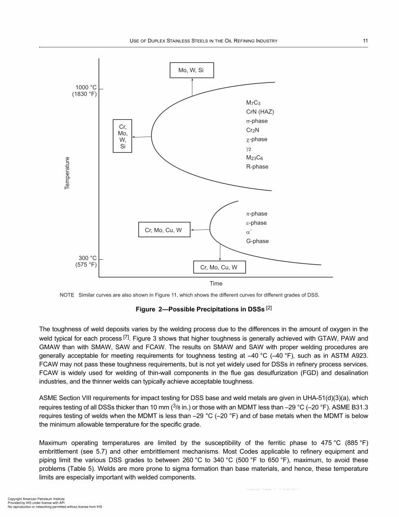
The formation of harmful intermetallic phases results from excessively high heat inputs or more accurately, excessive
cumulative time at high temperatures (700 °C to 955 °C [1300 °F to 1750 °F]), as shown in Figure 2. They are
extremely detrimental to impact toughness and corrosion resistance. [4], [5] The rate of this diffusion-controlled
process is most rapid at 815 °C to 870 °C (1500 °F to 1600 °F) and phase formation is cumulative with each
exposure. The exposure times shown below for having unacceptable amounts of intermetallic phase formation are
given to show a relative comparison between the alloy families and precise values would vary by composition and
other variables:
— for a 22 % Cr DSSs with nitrogen >0.14 %, about short times (significantly less than one hour) of exposure at
870 °C (1600 °F) will result in a significant loss of corrosion resistance and toughness;
— super and hyper DSSs will show similar degradation after even shorter times (minutes) at 850 °C (1560 °F);
— lean DSSs, such as S32304, are much more tolerant of time in this temperature range and can be exposed for
hours (typically over 10 hours) before being affected.
The cumulative exposures include the cooling time after the final annealing process and all welding (including future
repairs), hot forming, and thermal treatments (other than annealing).
Because the cooling provided by the work piece itself is the most effective method of reducing the time that the HAZ
and weld deposit are in the temperature range for formation of intermetallic phases, a low interpass temperature
during welding is desirable for minimizing the formation of intermetallic phases. The limit can vary based on the
welding procedure, metal thickness, and material grade, and typically is between 100 °C to 200 °C (210 °F to 390 °F).
Once intermetallic compounds form, they can only be removed by a full anneal with sufficient time at temperature to
dissolve the intermetallic compounds, followed by rapid cooling to prevent reformation. Such a treatment may not be
possible on a large fabrication, such as a vessel or tank. In that case, it would be necessary to cut out the affected
region and make a qualified repair.
4.4 Low and High Temperature Properties
DSSs with the proper structure can have adequate toughness for arctic ambient temperatures, but not for cryogenic
applications. Minimum allowable temperatures are –51 °C (–60 °F) in the ASME B31.3 Code and –29 °C (–20 °F) for
some cases in ASME Section VIII. These limits have qualifiers involving thickness, etc., and lower temperatures can
be used by impact testing the material [6]. Hence, actual limits are determined by reviewing the applicable Code.
Copyright American Petroleum Institute
Provided by IHS under license with API
No reproduction or networking permitted without license from IHS
--`,,,,,`,,,``,`,,,,,,``,```-`-`,,`,,`,`,,`---
USE OF DUPLEX STAINLESS STEELS IN THE OIL REFINING INDUSTRY 11
The toughness of weld deposits varies by the welding process due to the differences in the amount of oxygen in the
weld typical for each process [7]. Figure 3 shows that higher toughness is generally achieved with GTAW, PAW and
GMAW than with SMAW, SAW and FCAW. The results on SMAW and SAW with proper welding procedures are
generally acceptable for meeting requirements for toughness testing at –40 °C (–40 °F), such as in ASTM A923.
FCAW may not pass these toughness requirements, but is not yet widely used for DSSs in refinery process services.
FCAW is widely used for welding of thin-wall components in the flue gas desulfurization (FGD) and desalination
industries, and the thinner welds can typically achieve acceptable toughness.
ASME Section VIII requirements for impact testing for DSS base and weld metals are given in UHA-51(d)(3)(a), which
requires testing of all DSSs thicker than 10 mm (3/8 in.) or those with an MDMT less than –29 °C (–20 °F). ASME B31.3
requires testing of welds when the MDMT is less than –29 °C (–20 °F) and of base metals when the MDMT is below
the minimum allowable temperature for the specific grade.
Maximum operating temperatures are limited by the susceptibility of the ferritic phase to 475 °C (885 °F)
embrittlement (see 5.7) and other embrittlement mechanisms. Most Codes applicable to refinery equipment and
piping limit the various DSS grades to between 260 °C to 340 °C (500 °F to 650 °F), maximum, to avoid these
problems (Table 5). Welds are more prone to sigma formation than base materials, and hence, these temperature
limits are especially important with welded components.
Figure 2—Possible Precipitations in DSSs [2]
300 °C(575 °F)
1000 °C(1830 °F)
Tem
pe
ratu
reMo, W, Si
Cr,Mo,W,Si
Cr, Mo, Cu, W
Cr, Mo, Cu, W
Time
M7C3
CrN (HAZ)
-phase
Cr2N
-phase
2
M23C6
R-phase
-phase
-phase
´
G-phase
NOTE Similar curves are also shown in Figure 11, which shows the different curves for different grades of DSS.
Copyright American Petroleum Institute
Provided by IHS under license with API
No reproduction or networking permitted without license from IHS
--`,,,,,`,,,``,`,,,,,,``,```-`-`,,`,,`,`,,`---

12 API TECHNICAL REPORT 938-C
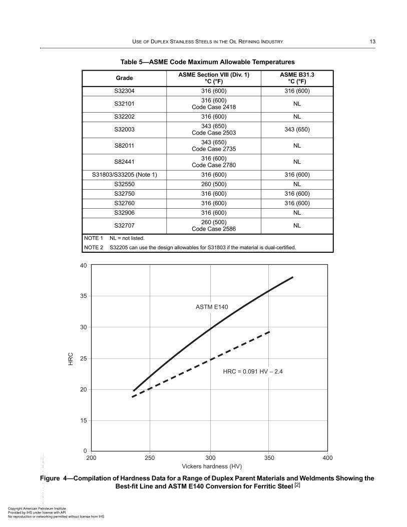
4.5 Hardness Conversions
The hardness conversions between the Rockwell C, Vickers and Brinell scales are different for DSSs as compared to
CS and other low-alloy, ferritic steels [2]. This is an important consideration when hardness limits from industry
standards in Rockwell C are applied to weld procedure qualifications, which are typically testing using a Vickers
method. The conversion chart given in ASTM E140 is often used, even though this chart was developed for CS and
low-alloy steels. It results in a conservatively low Vickers criteria for DSSs. This effect is shown by the curves in Figure
4. For example, for a desired limit of HRC 28, CS should use 286 HV, while DSSs should use 334 HV. Also relevant
for microhardness measurements is the possibility that the size and orientation of the two phases may be coarse
relative to the indenter size in certain products, such as cast DSSs.
Vickers hardness is the most practical and accurate hardness testing method for DSS welds, but the method of
preparation of the sample and the load used for the testing can strongly affect the results. Low loads are particularly
necessary for accurate measurement of HAZ hardness.
Figure 3—Effect of Weld Metal Oxygen Content on the Toughness of the Weld [7]
0
0
50
100
150
200
250
300
200 400 600 800 1000 1200 1400
GTAW, PAW
GMAW
SMAW, SAW
FCAW
Weld
Meta
l C
VN
Toughn
ess a
t +
20
°C
, J/c
m2
Weld Metal Oxygen Content, ppm
Copyright American Petroleum Institute
Provided by IHS under license with API
No reproduction or networking permitted without license from IHS
--`,,,,,`,,,``,`,,,,,,``,```-`-`,,`,,`,`,,`---
USE OF DUPLEX STAINLESS STEELS IN THE OIL REFINING INDUSTRY 13
Table 5—ASME Code Maximum Allowable Temperatures
GradeASME Section VIII (Div. 1)
°C (°F)ASME B31.3
°C (°F)
S32304 316 (600) 316 (600)
S32101316 (600)
Code Case 2418NL
S32202 316 (600) NL
S32003343 (650)
Code Case 2503343 (650)
S82011343 (650)
Code Case 2735NL
S82441316 (600)
Code Case 2780NL
S31803/S33205 (Note 1) 316 (600) 316 (600)
S32550 260 (500) NL
S32750 316 (600) 316 (600)
S32760 316 (600) 316 (600)
S32906 316 (600) NL
S32707260 (500)
Code Case 2586NL
NOTE 1 NL = not listed.
NOTE 2 S32205 can use the design allowables for S31803 if the material is dual-certified.
Figure 4—Compilation of Hardness Data for a Range of Duplex Parent Materials and Weldments Showing the
Best-fit Line and ASTM E140 Conversion for Ferritic Steel [2]
200
0
15
20
25
30
35
40
250 300 350 400
HRC = 0.091 HV – 2.4
ASTM E140
HR
C
Vickers hardness (HV)
Copyright American Petroleum Institute
Provided by IHS under license with API
No reproduction or networking permitted without license from IHS
--`,,,,,`,,,``,`,,,,,,``,```-`-`,,`,,`,`,,`---

14 API TECHNICAL REPORT 938-C
5 Potential Environment-Related Failure Mechanisms
5.1 Chloride Pitting and Crevice Corrosion
Because DSSs are generally designed with higher Cr levels than the austenitic stainless grades, and because the
duplex grades readily accept alloying with molybdenum and nitrogen, various DSSs grades have significantly better
chloride pitting and crevice corrosion resistance than the standard austenitic SS, such as 304L and 316L (UNS
S30403 and S31603). The most common tools for predicting the chloride pitting resistance of corrosion resistant
alloys are the PREN and CPT. The PREN is a statistical regression relationship based on the effect of composition on
CPT in a particular test environment, such as ASTM G48, for many commercial grades. The PREN correlates the
chloride pitting resistance provided by the contributing elements in the alloy composition, namely chromium,
molybdenum, nitrogen, and tungsten, as long as the elements are present in a “balanced” composition, as reflected in
the established grades. Two commonly reported equations are given below. There are several variations reported in
the literature, however, the following are the most prevalent (with the second formula being used by many industry
standards including, NACE MR0175/ISO 15156).
PREN = % Cr + 3.3 × % Mo + 16 × % N
PREN = % Cr + 3.3 × (% Mo + 0.5 × % W) + 16 × % N
While PREN is useful in roughly ranking alloys, other material factors may play a role in the chloride pitting resistance,
such as the surface finish, welding quality, and other fabrication details. In addition, with DSSs (especially for grades
with an overall PREN less than about 40), the two phases will have partitioning of the alloying elements, and hence,
can have a different PREN for each phase. For most DSSs material from experienced suppliers, this has not been a
significant problem as these suppliers strive to balance the PREN between the two phases. In standard duplex SS
grades, the austenite grains can have a lower PREN, and in the lean duplex SS grades, the ferrite grains can be
lower PREN compared to the PREN based on overall chemistry. In some severe services, such as some flue gas
desulfurization units, this has led to selective attack of the phase with the lower PREN. Some examples of alloy
partitioning for 25 Cr DSSs are shown in Table 4 and Table 8, which are part of 4.2 and 5.6 of this report, respectively.
Service factors affecting the aggressiveness of chloride pitting environments include temperature, chloride
concentration, oxygen content, other oxidizing species, and pH. One of the most common tests for determining the
CPT is the ASTM G48 Test Method E (formerly ASTM G48 Test Method C) test, which is run in an acidified aqueous
solution of ferric chloride having about 6 % FeCl3 by mass and about 1 % HCl. Results of ASTM G48 CPT tests in
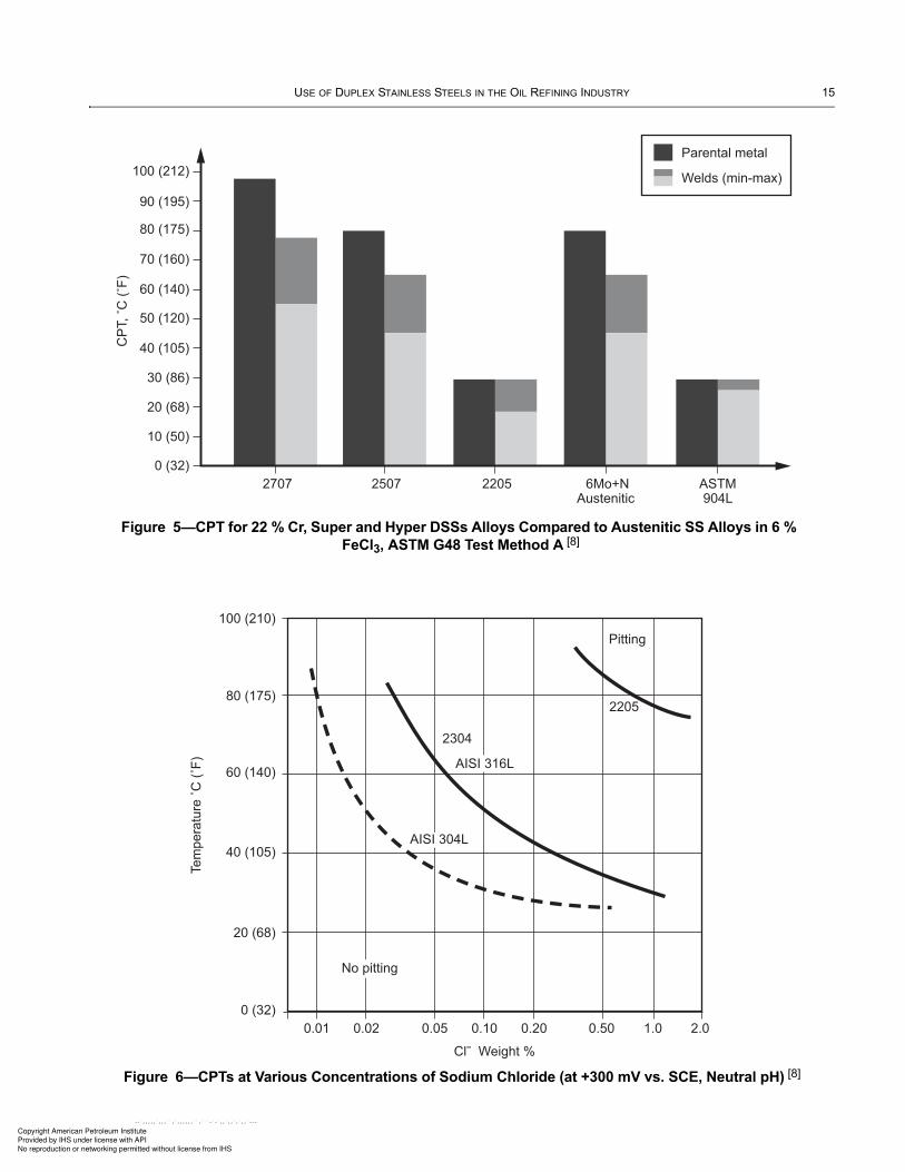
ferric chloride on various duplex and austenitic SS grades are shown in Figure 5 [8] and Figure 7 [9]. Figure 6 shows
the critical pitting temperatures at various concentrations of sodium chloride at neutral pH for 304L, 316L, UNS
S32304 and UNS S32205 [8].
One test program targeted for the refining industry measured the resistance of various alloys to 20 wt.% and 40 wt.%
ammonium chloride solutions and it showed excellent resistance of Super DSS with a PREN of 40 or higher [9].
However, a second test program showed pitting of Super DSS under an ammonium chloride salt deposit when the
relative humidity was 50 % and 60 % (the testing was done at 80 °C). This test program also studied the critical
relative humidity (CRH) of ammonium chloride salt deposits at different temperature, which also had an effect on the
corrosion [10].
Crevice corrosion resistance is similarly shown by a CCT that is commonly determined by ASTM G48 Test Method F
(formerly ASTM G48 Test Method D) test. This test gives lower temperature results, which indicate that it is a more
severe test. Figure 7 shows CCT results on duplex and austenitic SSs. The CCT is a function of the severity of the
crevice, including the selection of the crevice forming material.
Corrosion under insulation (CUI) is due to wet insulation forming aqueous chloride-containing solutions on the metal
surfaces. These conditions can cause corrosion on carbon steel, austenitic SS or DSS, and chloride stress corrosion
cracking (SCC) on austenitic SS or DSS. NACE SP0198, “Control of Corrosion Under Thermal Insulation and
Fireproofing Materials—A Systems Approach” addresses this concern and gives recommended coating systems.
Copyright American Petroleum Institute
Provided by IHS under license with API
No reproduction or networking permitted without license from IHS
--`,,,,,`,,,``,`,,,,,,``,```-`-`,,`,,`,`,,`---
USE OF DUPLEX STAINLESS STEELS IN THE OIL REFINING INDUSTRY 15
Figure 5—CPT for 22 % Cr, Super and Hyper DSSs Alloys Compared to Austenitic SS Alloys in 6 %
FeCl3, ASTM G48 Test Method A [8]
Figure 6—CPTs at Various Concentrations of Sodium Chloride (at +300 mV vs. SCE, Neutral pH) [8]
10 (50)
30 (86)
20 (68)
0 (32)
2707
Parental metal
Welds (min-max)
2507 2205 6Mo+NAustenitic
ASTM904L
40 (105)
80 (175)
60 (140)
100 (212)
50 (120)
70 (160)
90 (195)
0.01 0.02 0.05 0.10 0.20 0.50 1.0 2.0
0 (32)
20 (68)
40 (105)
60 (140)
80 (175)
100 (210)
AISI 316L
AISI 304L
No pitting
Pitting
2205
2304
Copyright American Petroleum Institute
Provided by IHS under license with API
No reproduction or networking permitted without license from IHS
--`,,,,,`,,,``,`,,,,,,``,```-`-`,,`,,`,`,,`---

16 API TECHNICAL REPORT 938-C
Duplex SS is more resistant than austenitic SS to corrosion and SCC, but not immune as shown by the following
excerpt from NACE SP0198:
“The higher-nickel, chromium, and molybdenum-containing austenitic stainless steel alloys and the lower-nickel,
higher-chromium duplex stainless steel alloys have been found to be more resistant to SCC under thermal
insulation, but are not immune. For example, recent offshore experience found that under severe conditions,
duplex stainless steels also can suffer from external SCC under insulation. Protective coatings and systems
may be used to mitigate the threat associated with CUI of austenitic and duplex stainless steels.”
Hence, DSS components which are insulated and in an area where the climate or atmospheric conditions and
temperature range create a risk of external chloride SCC, are typically protected by coating, using thermal spray
aluminum (TSA) or wrapping with foil in a similar manner as specified for austenitic SS. Other industry standards,
including some in Europe, are also adopting similar requirements.
5.2 Corrosion in Seawater
Although all the variables mentioned in 5.1 are important factors for corrosion resistance in seawater, there are rules-
of-thumb that have been developed. Experience has shown that SS typically need a PREN ≥40 to resist pitting and
crevice corrosion in ambient temperature seawater. Seawater corrosion is a highly complex situation where aeration,
filtration, biofouling and biofouling control, and salinity lead to corrosion behavior that is not necessarily directly
proportional to temperature. This makes the acceptability of 22 % Cr DSSs difficult to predict, hence, 25 % Cr Super
DSSs that meet the minimum PREN of 40 are more commonly used in seawater-cooled heat exchangers. 27 % Cr
Hyper DSS can be used in seawater applications at higher temperatures than Super DSSs.
The super and hyper duplex SS grades (PREN ≥40) have shown excellent resistance to general and localized
corrosion in polluted and unpolluted seawater. They can also be considered to have good resistance to stress
corrosion cracking in seawater service (see Section 5.3). These alloys also possess good erosion resistance in
seawater heat exchanger tubing applications when exposed to fluid velocities up to 10 m/s (32.8 ft/s).
Figure 7—CPTs and CCTs for 22 % Cr and Super DSSs Compared to
Austenitic SS Alloys in ASTM G48 Tests
0316L 317LMN
10
20
30
40
50
60
70
NOTE 27 % Cr Hyper DSS is reported to have a minimum CCT of 70 °C based on ASTM G48 testing .
N 08904 N 08926 S 31266 N 06625 S 31803 S 32205 S 32750 S 32520
CPT (°C)
CCT (°C)
[11], [12]
Copyright American Petroleum Institute
Provided by IHS under license with API
No reproduction or networking permitted without license from IHS
--`,,,,,`,,,``,`,,,,,,``,```-`-`,,`,,`,`,,`---

USE OF DUPLEX STAINLESS STEELS IN THE OIL REFINING INDUSTRY 17
It is common practice that seawater cooling water is chlorinated to control biofouling. Chlorination increases the
corrosion potential that causes localized corrosion attack. The maximum tube metal temperature limit for duplex SS
grades is lower with chlorinated seawater than in natural seawater.
Seawater also has normally a high amount of dissolved calcium and carbon dioxide that respects the chemical
equilibrium below:
Very often it is only the seawater that comes into contact with the hot tube wall that reaches sufficient temperatures to
cause corrosion. At approximately 60 °C (140 °F), seawater begins to decompose, driving CO2 from the system and
pushing the chemical equilibrium to the right, thus precipitating CaCO3. The higher temperatures under the CaCO3
deposits can lead to the deposition of sulfates, carbonates and other salts on the tube wall. If the higher temperature
approaches the boiling point, chloride salts can also deposit giving a very aggressive set of conditions. These
deposits and high temperatures can lead to a risk of crevice/underdeposit corrosion within a short time after their
formation.
In a modified version of ASTM G48A, test samples are exposed for periods of 24 hours in 6 % FeCl3. This solution
has a corrosion potential of +600 mV that is equivalent to continuously chlorinated seawater’s potential. When pits are
detected together with a substantial weight loss (> 5 mg), the test is interrupted. Otherwise, the temperature is
increased 5 °C (9 °F) and the test is continued. The CPT of S32707 defined in this way was 97.5 ˚C (207.5 °F),
compared to approximately 80˚C (176 °F) for S32750 [11], [12].
A typical limit for Super DSS (with PREN ≥40) heat exchanger tubing in seawater is 60 °C (140 °F) at flow velocities
of 1.5 m/s (5 ft/s), minimum. However, if there is a risk of deposits or if the seawater is chlorinated, the limit is
suggested to be reduced to 50 °C (120 °F). An additional requirement is that incoming seawater should be filtered in
order to reduce silt and sand deposits that promote corrosion. However, the calcium carbonate fouling described
above cannot be prevented by filtration or maintaining flow rates and hence, is typically the defining factor when it
comes to using super duplex and other stainless steels in chlorinated seawater cooling applications. For seawater-
cooled heat exchangers working with metal temperatures above this critical temperature of 60 °C (140 °F), there is a
risk of underdeposit corrosion. Hyper DSSs show improved resistance and are being used in some cases up to 70 °C
(160 °F), with or without continuous chlorination [11].
5.3 Chloride Stress Corrosion Cracking (CSCC)
The risk of CSCC restricts the use of standard austenitic SS grades, such as 304L and 316L, based on chloride
concentrations, temperatures and various other factors. Depending on the chloride concentration in the bulk solution
along with consideration of concentrating mechanisms (such as hot surfaces, underdeposits or crevices), actual
metal temperature, acidity/pH, tensile stress, time of exposure, and oxygen content, CSCC can cause rapid failures.
In most cases, temperatures greater than 60 °C (140 °F) are a risk for cracking of those austenitic SS grades, with
cracking tendency increasing with increasing metal temperature. However, the risk of CSCC is dependent upon all of
the listed factors, and in severe cases, CSCC can occur at slightly lower temperatures.
DSSs are a common “replacement” or alternative material in services where the threat of CSCC makes 300 series
SSs a poor or marginal alloy choice. Practical experience and laboratory testing have shown DDSs to have good
resistance to CSCC, but they are not immune [8], [13]. Figure 8 and Figure 9 present results of tests that compared
various grades of DSSs with other alloys in chloride solutions. Results from high-pressure autoclave tests in neutral,
oxygenated chloride solutions are shown in Figure 8 [8]. The tests indicate the comparative cracking thresholds
versus chloride concentrations and temperatures for various alloys.
Figure 9 shows the results of constant-load tests in an aerated, 40 % calcium chloride solution, acidified to a pH of 1.5
at 100 °C (212 °F) [8]. Time to failure is shown as a function of the loading level. The results show that the DSSs have
a much higher resistance to SCC under these conditions than does austenitic SS.
Ca2+
aq( ) 2HCO aq( ) –
3+ CaCO s( )3↔ CO g( )2 H2O+ +
Copyright American Petroleum Institute
Provided by IHS under license with API
No reproduction or networking permitted without license from IHS
--`,,,,,`,,,``,`,,,,,,``,```-`-`,,`,,`,`,,`---

18 API TECHNICAL REPORT 938-C
Figure 8—CSCC Resistance of DSSs Alloys Compared to Austenitic SS Alloys in Oxygen-bearing
Neutral Chloride Solutions [8]
Figure 9—Results of SCC Tests of 22 % Cr and 25 % Cr DSSs Alloys Compared to Austenitic SS
Alloys in Constant Load Tests in 40 % CaCl2, 1.5 pH at 100 °C with Aerated Test Solution [8]
0
0.80.60.40.20 1.00
100
300
200
400
500
600
AISI 316L
Stress/tensile strength
2205
2507
Tim
e to failu
re, h
Copyright American Petroleum Institute
Provided by IHS under license with API
No reproduction or networking permitted without license from IHS
--`,,,,,`,,,``,`,,,,,,``,```-`-`,,`,,`,`,,`---

USE OF DUPLEX STAINLESS STEELS IN THE OIL REFINING INDUSTRY 19
Additional considerations for predicting susceptibility of a DSS to CSCC include the following.
a) Chloride concentration can build up under boiling conditions, in the water film in contact with a heat-rejecting
surface, under deposits or in a crevice. Cases of CSCC have occurred on Standard and Super DSSs which were
exposed to chloride salt deposits, resulting in extremely high localized chloride concentrations, and some of these
cases were at surprisingly low temperatures [14], [15], [16], [17], [18]. The various types of chloride salts (such as Na,
Mg, Ca, Fe, NH4, Li, etc.) also showed variations in severity.
b) High pH environments, such as those containing NH4HS (ammonium bisulfide), amine, or caustic, are expected to
have higher thresholds for CSCC than neutral or acidic solutions.
c) Wet-dry conditions, as may occur when water drips on a hot metal surface, can be especially aggressive because
of localized thermal fatigue and/or crevice corrosion originating CSCC from the deposits formed as the water
evaporates (in some cases external coatings have been recommended on duplex SS components exposed to
seawater splashing which operate above 100 °C (212 °F) [19].
d) H2S may interact with chlorides to cause greater susceptibility to cracking, especially in acidic pH conditions, but
these interactions are still under investigation.
There have been a few reported cases of cracking in the industry, but most were under severe conditions where SCC
could be predicted. Some of those examples have occurred in offshore facilities and were attributed to external SCC
on relatively hot equipment. One case of internal CSCC on an offshore platform occurred on 22 % Cr DSSs after only
a few weeks of service. The conditions were 200,000 ppm to 460,000 ppm Cl, pH 3.4, 140 °C (284 °F) and no oxygen
(<1 ppb). There is one example of CSCC of a 25 % Cr DSSs in a crude unit application with chloride salt deposits
shown in Table 11, and other examples of CSCC from refinery services reported in NACE Refin-Cor are summarized
in Table 10 (these tables are part of Section 8 in this report).
CUI can also lead to corrosion or CSCC of DSSs, as discussed in 5.1 of this report.
5.4 Hydrogen Stress Cracking (HSC)/Sulfide Stress Cracking (SSC)
Many services where DSSs are used in refineries involve a water phase containing H2S, and hence, there is a risk of
HSC.
The behavior of DSSs with H2S aqueous solutions is dependent on the type of sulfur present in the environment. In
the water phase, there is a balance of H2S, HS– and S2–, as a function of the pH. The reactions for each pH level are
described below:
Fe + H2S = FeS + 2H+ (acid pH)
Fe + HS- = FeS + H+ + 2e (neutral pH)
Fe + S2– = FeS + 2e (basic pH)
One form of HSC is sulfide stress cracking (SSC), which can occur in high-strength (hard) zones of base materials or
welds. SSC susceptibility is dependent on many variables: partial pressure of H2S, pH, chloride content, temperature,
microstructure, hardness, cold work, surface finish, etc. In the NACE TM0177 test for SSC, most DSSs do not show
any cracking until the applied stress is well above the proof strength. Cold work decreases the threshold failure
stress.
Numerous fabrication requirements can be specified to minimize hardness and hence, susceptibility to these cracking
mechanisms. There has also been extensive testing done on DSSs resistance at acidic pHs to understand and avoid
this cracking. Although there is controversy on the test methods and the ability to compare results between different
test programs or to service conditions, the results have allowed some limits to be established on the use of different
Copyright American Petroleum Institute
Provided by IHS under license with API
No reproduction or networking permitted without license from IHS
--`,,,,,`,,,``,`,,,,,,``,```-`-`,,`,,`,`,,`---

20 API TECHNICAL REPORT 938-C
alloys. Note that the conditions in wet sour environments in oil production generally vary from those in refining.
Production environments typically also contain carbon dioxide and bicarbonate ions and are lower than neutral pH,
while many of the applicable refining environments contain high amounts of ammonia, and are higher than neutral
pH. Also, production environments often contain significantly higher levels of chlorides.
For solution annealed DSS materials, NACE MR0175/ISO 15156 gives varying PREN, temperature, H2S partial
pressure, and ferrite content limits (35 % to 65 % for wrought and cast materials, and 30-70% for welds), with any
chloride levels required for different grades of DSSs to prevent SSC. For these cases, it does not require a hardness
limit for the services within its scope. The process limits were developed specifically for the oil and gas production
industry, and were based on experience and laboratory testing focused on producing environments. Refining
environments have significant differences in pH, other contaminants, etc., and hence, the NACE MR0175 limits are
not always applicable. Refining applications of DSSs have often exceeded, and sometimes significantly, the H2S
partial pressure limits in NACE MR0175, and the DSSs have provided good resistance.
A separate table in NACE MR0175/ISO 15156 applies to cold-worked DSS materials, but the title of the table
indicates that it applies only to “downhole tubular, packers or other subsurface components”. For DSSs with various
PRENs, limits are given on H2S partial pressure, and in some cases, chloride contents, in addition to a hardness limit
of 36 HRC, maximum. Some users in the production industry reportedly apply this table to additional cold worked
components besides those listed in the table title.
Additional research is being done in oil and gas environments to possibly raise the NACE MR0175/ISO 15156 limits,
but this research may not be directly applicable to many of the high pH SSC environments in refineries. Table 6 and
Table 7 present data from recent papers [20], [21].
A second NACE standard is MR0103, which is similar to older versions of NACE MR0175, but is targeted for the
refining industry. It limits DSSs base materials in severe wet sour services to 28 HRC maximum hardness for PREN
≤40 and 32 HRC for PREN >40. For the weld procedure qualification, it specifies that the average hardness shall not
exceed 310 HV and no individual reading shall exceed 320 HV. Additional research is needed on this topic to optimize
these hardness limits in refining services.
Some SSC failures in refinery applications have been attributed to improper fabrication which led to ferrite contents
and/or hardnesses in some zones of the weldment being outside of specified limits. The suggested hardness limit of
310 HV, average (320 HV max), for Standard DSS weld procedure qualification given in API 582 for S31803/S32205,
along with the tight control of welding variables helps ensure that the production welding matches the qualified
procedures, which are the primary means of minimizing the risk of HSC/SSC. Super and Hyper DSSs require a
higher hardness limit due to their higher yield strength and testing indicates they are acceptable to higher values.
Table 6—Estimated H2S Partial Pressure Limits for DSS in Production Services Based on Literature,
Laboratory and Experiential Data (KPa [psi]) [20]
22 % Cr DSS 25 % Cr Super DSS
Chlorides pH 3.5 pH 4.5 pH 3.5 pH 4.5
1000 ppm 50 (7.25) >200 (29.0) 70 (10.15) >200 (29.0)
10,000 ppm 30 (4.35) 200 (29.0) 50 (7.25) >200 (29.0)
100,000 ppm 20 (2.90) 30 to 40 (4.35 to 5.80) 30 (4.35) 80 to 100 (11.6 to 14.5)
NOTE 1 This table is applicable to solution annealed materials.
NOTE 2 These limits have not been confirmed for welds.
NOTE 3 The variables of temperature and applied stress are considered to be “incorporated” and these limits encompass all practical ranges for wet sour applications at these pH ranges, which meet design codes.
NOTE 4 Higher pH (>8 or 9) refinery services may not be represented by this data.
Copyright American Petroleum Institute
Provided by IHS under license with API
No reproduction or networking permitted without license from IHS
--`,,,,,`,,,``,`,,,,,,``,```-`-`,,`,,`,`,,`---

USE OF DUPLEX STAINLESS STEELS IN THE OIL REFINING INDUSTRY 21
In 2011 through 2013 about seven cases of weld cracking were reported in hydroprocessing unit REAC services.
They were in some of the most severe refining environments with high NH4HS concentrations, high pressures and
high H2S partial pressures. The thickness at the welds were generally >25 mm (which resulted from the high pressure
service). Some cases were attributable to poor fabrication and were confirmed to have high hardness and/or high
ferrite contents in the weld or HAZ, which then led to SSC cracking. However, in other cases equipment seemed to be
fabricated using good industry practices [22]. These cases have been added to Table 11 and are currently under
further investigation (primarily by the Materials Technology Institute in a 2013-2014 program) with the objective of
developing additional fabrication and/or non-destructive testing (NDE) steps applicable to thick-wall duplex SS air
coolers and other components to help ensure their resistance to SSC and NH4HS corrosion in these environments.
5.5 Ammonium Bisulfide Corrosion
There is some laboratory data showing the resistance of DSSs to ammonium bisulfide environments [23], [24], and
extensive experiential data as shown by the examples included in Table 10 and Table 11 [25]. Case histories come
from hydroprocessing, sour water strippers, FCC and coker units. Duplex 2205 is one of the commonly-used alloys for
REACs under relatively severe conditions and was shown by an extensive testing program to be just slightly below
Alloy 825 in NH4HS (ammonium bisulfide) corrosion resistance. Super DSS was shown to have resistance slightly
superior to Alloy 825 and Alloy 625, and just slightly below Alloy C-276 [24]. Another good reference on the use of
DSSs in REACs is API 932-B.
There are numerous case histories of DSSs applications in hydroprocessing units with NH4HS concentrations up to
10 %. However, it is important to consider that there are other critical variables affecting the acceptability of, and
threshold NH4HS concentration for DSSs, including velocity (shear stress), H2S partial pressure, temperature, water
injection distribution and contacting, water quality, chlorides, etc. A proprietary joint research program was sponsored
by interested companies to collect data on NH4HS corrosion. The program was initiated in March 2000 and
concluded the initial phase of work in February 2003, and second and third phases shortly after [26]. Results of this
work have better defined the roles of several key variables on corrosion behavior, and developed a software program
called Predict-SW, which gives predicted NH4HS corrosion rates for various materials [24]. Some new applications
have used 9.1 m/s (30 ft/s) as the maximum velocity for Standard DSSs; however, this limit may be conservative in
many cases.
One case of DSS failing due to NH4HS corrosion in a sour water stripper (SWS) is listed in Table 10; however, the
NH4HS concentration was not reported. The environment in SWSs is different than in REACs, as SWS environments
are low pressure, do not have hydrocarbons, can have greater NH3 than H2S (in partial pressures), can have NH4HS
concentrations up to 25 %, etc. The Predict-SW software mentioned above also gives guidance for SWS
environments [24].
Table 7—Successful Service Experience with DSS in Production Sour Services [20]
DSSGrade
H2S PP[Kpa (psi)]
Temperature(°C)
pHChlorides
(ppm)Duration(years)
22 % Cr 25 (3.63) 80 6 8,000 8
22 % Cr ~1000 (145.0) 60 to 110 4.5 20 to 50,000 >3
22 % Cr ~400 (58.0) 40 to 60 3.7 <100 >10
22 % Cr 160 to 500 (23.2 to 72.5) 40 to 60 3.5 <100 >5
22 % Cr 75 (10.9) 50 to 80 4.7 25,000 6
25 % Cr 5.0 (0.73) <200 3.5 175,000 10
25 % Cr 125 (18.1) <125 4.2 25,000 6
Copyright American Petroleum Institute
Provided by IHS under license with API
No reproduction or networking permitted without license from IHS
--`,,,,,`,,,``,`,,,,,,``,```-`-`,,`,,`,`,,`---

22 API TECHNICAL REPORT 938-C
Recent reported SSC failure cases of duplex heavy wall (>25 mm [1 in.]) welded REACs have occurred on welds that
did not show obvious signs of improper fabrication. Further study is being done on these failures to optimize the
specifications for thick wall fabrication. Additional discussion on these failures and concerns is given in the previous
section of this report and they are listed in Table 11.
In air coolers (especially REACs) with a risk of wet ammonium chloride salt deposits, DSSs could be susceptible to
chloride pitting, as discussed above in 5.1. These deposits are extremely corrosive to almost all alloys, and hence,
the deposit formation should be prevented by process measures, such as water washing or maintaining a minimum
temperature, rather than attempting to prevent corrosion with metallurgy [26]. The presence of cyanides at levels
above about 20 ppm can also greatly increase the risk of NH4HS corrosion on almost all alloys, except the nickel-
based alloy C family. DSS piping has shown cyanide-related NH4HS corrosion in a Sour Water Stripper overhead with
80 ppm to 90 ppm cyanides [27].
5.6 Naphthenic Acid Corrosion
Naphthenic acid corrosion occurs primarily in crude units due to organic, carboxylic acids in the crude oil and distilled
cuts. The temperature range where it occurs is approximately 175 °C to 425 °C (350 °F to 800 °F), and the primary
variables affecting the corrosion rates are organic acid concentration, temperature, velocity, and sulfur content and
species. Molybdenum content is important for naphthenic acid corrosion resistance and alloys with 2.5 % minimum
Mo provide acceptable corrosion resistance in most cases.
There are little or no published laboratory data and minimal documented experiential data for DSSs in naphthenic
acid refining services. One case alleged the successful use of SDSS, grade S32707, in a crude preheater which was
known to encounter conditions which could cause naphthenic acid corrosion. Also, based on the numerous times
DSS has been specified for this service, there are probably many other recent applications currently in service. Some
industry materials experts believe DSS grades with ≥2.5 % Mo to have good naphthenic acid corrosion resistance
based on their alloy content, however, partitioning on the molybdenum between the austenitic and ferritic phases
needs to be considered, as discussed below.
In most areas susceptible to naphthenic acid corrosion, 317L austenitic SS which has a specified Mo content of 3 %
to 4 % has displayed excellent resistance, but there are some services where 317L SS has not performed adequately
or is deemed undesirable. Examples are heat exchanger tubing with a hot, naphthenic stream on one side and either
un-desalted crude, crude tower overhead or steam generating on the other side. 317L SS, although resistant to
naphthenic acid corrosion, would have risks of CSCC from the other side’s service. DSSs will have superior CSCC
resistance, as discussed in 5.3, but would be limited to 260 °C to 340 °C (500 °F to 650 °F) design temperatures
based on Code limits (shown in Table 5).
Partitioning of the molybdenum between the two phases of DSSs could affect the overall naphthenic acid corrosion
resistance. Early papers on DSS alloy development showed that the partitioning results in a ratio of 1.5 to 1.6 for Mo
in the ferrite to austenite phases [2], [4]. This means that the austenite phase may have as low as 38.5 % of the “bulk”
Mo content. Table 8 depicts some examples of partitioning in various DSS alloys and welds.
5.7 475 °C (885 °F) Embrittlement
Prolonged exposures at above 260 °C to 340 °C (500 °F to 650 °F) depending on grade, may initiate embrittlement in
DSSs. This phenomenon is most rapid at about 475 °C (885 °F), hence, it is known as “475 °C embrittlement.” The
mechanism causing the embrittlement is decomposition of the ferrite into a brittle, Cr-rich alpha prime phase. This is
the primary reason that the Code temperature limits are in the 260 °C to 340 °C (500 °F to 650 °F) range and
indicates that the DSSs should not be used for long durations above the Code limits.
The susceptibility to degradation of the base materials due to short-term exposures is shown in Figure 10 and
Figure 11 [2], [4]. The 25 % Cr and 27 % Cr alloys are more susceptible to this embrittlement than are UNS S32205 or
S32304, and they can embrittle from a room temperature toughness level of >150 J (111 ft-lb) to 27J (20 ft-lb) from 10
hours of exposure to 475 °C (885 °F). Similar levels of embrittlement would take >10,000 hours at 300 °C (570 °F).
This embrittlement will also occur more rapidly in weld metals than in base material.
Copyright American Petroleum Institute
Provided by IHS under license with API
No reproduction or networking permitted without license from IHS
--`,,,,,`,,,``,`,,,,,,``,```-`-`,,`,,`,`,,`---

USE OF DUPLEX STAINLESS STEELS IN THE OIL REFINING INDUSTRY 23
Table 8—Partitioning of Alloying Elements Between Phases
A—In 25 % Cr Alloys [27]
Sample PhasePhase
Volume %
Cr
(wt. %)
Ni
(wt. %)
Mo
(wt. %)
Fe
(wt. %)
N
(wt. %)PREN
1 aAustenite 65 24.5 8.3 2.9 Bal.
Ferrite 35 29.3 3.9 4.3 Bal.
2 aAustenite 65 25.4 8.5 3.3 Bal.
Ferrite 35 29.3 4.8 5.0 Bal.
3 bAustenite 23.5 8.2 3.5 0.48 42.7
Ferrite 26.5 5.8 4.5 0.06 42.3
a Estimated volume fraction of phases determined by backscattered SEM analysis. Chemical composition analysis of phases determined by
STEM/EDS analysis (nitrogen cannot be obtained using this testing equipment).
b Chemical composition and PREN numbers of individual phases of 25-7-4 quench-annealed at 1075 °C (1967 °F).
B—In 22 % Cr Weld Metals (Approx. Wt. %) [28]
Weld Metal Type Phase Cr Ni Mo N PREN
22 Cr-10 Ni-3 Mo-0.12 NAustenite 20 to 21.5 10.5 to 11.5 2.5 to 3 0.2 to 0.5 31.5 min
Ferrite 22 to 23.5 8.5 to 9.5 3 to 3.5 < 0.05 32 min
22 Cr-6 Ni-3 Mo-0.12 NAustenite 21 to 24 5.5 to 8 2.5 to 3.5 0.3 to 0.6 34 min
Ferrite 21 to 24 5.5 to 8 2.5 to 3.5 < 0.05 29 min
22 Cr-6 Ni-3 Mo-0.18 NAustenite 21 to 22 6 to 8 2.5 to 3 0.3 to 0.6 34 min
Ferrite 22 to 24 5 to 6 3 to 4 < 0.05 32 min
C—In 22 % Cr Base Metal and SMAW Weldments with Varying Arc Energy (Wt. %) [28]
Weld Region Phase Cr Ni Mo
Parent SteelAustenite 19.5 7.0 2.4
Ferrite 23.2 4.1 3.3
As-deposited Root aAustenite 23.7 7.8 2.8
Ferrite 23.9 7.5 3.0
Reheated Root aAustenite 23.4 7.7 2.7
Ferrite 23.7 7.2 3.0
As-deposited Root bAustenite 23.7 7.7 2.5
Ferrite 23.8 7.2 2.7
Reheated Root bAustenite 22.7 8.6 2.5
Ferrite 25.1 6.2 3.7
As-welded HAZ bAustenite 21.3 5.7 2.7
Ferrite 21.3 5.6 2.9
Reheated HAZ bAustenite 20.9 5.9 2.9
Ferrite 21.9 5.2 3.4
a Root and fill passes at 0.7 kJ/mm.
b Root at 0.5 kJ/mm, fill passes at 3.2 kJ/mm.
Copyright American Petroleum Institute
Provided by IHS under license with API
No reproduction or networking permitted without license from IHS
--`,,,,,`,,,``,`,,,,,,``,```-`-`,,`,,`,`,,`---

24 API TECHNICAL REPORT 938-C
6 Material Specifications
6.1 Typical Specification Requirements for Wrought Materials
Most users of DSSs in the petroleum industry have found that to ensure adequate corrosion and cracking resistance
in service, special requirements need to be added to the purchase order for both the material and fabrication. The
special material requirements are discussed in this section, while the fabrication requirements are provided in
Section 7. The material requirements are added to the applicable ASME/ASTM specifications listed in Table 2. Annex
A is an example of a specification containing the typical added material requirements for wrought products.
A nitrogen content of 0.14 %, minimum, in base metals of 22 % Cr DSSs is required in most refining services to
ensure adequate corrosion and environmental cracking resistance at welds. Therefore, if UNS S31803, which has a
specified nitrogen range of 0.08 % to 0.20 % is being used, it needs to be restricted to 0.14 % to 0.2 % nitrogen. UNS
S32205 meets the required nitrogen range, as shown in Table 1, but presently is not in the ASME Code in all wrought
product forms. It is believed that this situation will be remedied with time, as S32205 is being added to each wrought
product specification as they are revised.
A water quench after final anneal is another common requirement specified to ensure the desired corrosion
resistance. This minimizes the time the DSS is in the 982 °C to 705 °C (1800 °F to 1300 °F) range. One exception is
that ASTM A480 permits air cooling of sheet and tubing when the sheet is processed in a continuous anneal and
pickle line, but this is acceptable, as this method of cooling is very fast on thin sheets. For plates of even moderate
thicknesses, simple air cooling will not yield the optimal condition. Rapid cooling is necessary to minimize the
intermetallic phase content of the base material, particularly for material that is to be subsequently welded. The effect
of time in the temperature range for the formation of intermetallic phases is cumulative, and quenching will help to
reserve this time for welding and to ensure that the starting condition of the base metal will be uniform and consistent.
D—In 22 % Cr Base Metal and GTAW Weldment (Wt. %) [28]
Weld Region Phase Cr Ni Mo
Unfilled Weld RootAustenite 22.2 6.9 2.7
Ferrite 22.4 6.2 3.1
Reheated Weld RootAustenite 22.1 7.4 2.8
Ferrite 22.7 6.6 3.3
E—In 22 % Cr DSS Base Metal
Cr Ni Mo
Austenite Grain 1 20.90 6.64 2.48
Austenite Grain 2 20.09 6.99 2.22
Austenite Grain 3 20.04 7.01 2.19
Ferrite Grain 1 23.79 4.31 3.68
Ferrite Grain 2 23.61 4.36 3.73
Ferrite Grain 3 23.81 4.32 3.63
F—In 25 % Cr DSS Base Metal [29]
Cr Ni Mo N
Austenite 23.5 8.2 3.5 0.48
Ferrite 26.5 5.8 4.5 0.06
Copyright American Petroleum Institute
Provided by IHS under license with API
No reproduction or networking permitted without license from IHS
--`,,,,,`,,,``,`,,,,,,``,```-`-`,,`,,`,`,,`---

USE OF DUPLEX STAINLESS STEELS IN THE OIL REFINING INDUSTRY 25
Figure 10—Impact Energy Curves for Alloys Aged at 300 °C and 325 °C:
a) Quench Annealed S32750; b) 45 % Cold Worked S31803 [2] [°C = (°F – 32)/1.8]
Temperature (°C)
-200 -100 100
Impact
str
ength
(J/c
m2)
0
(b)
2000
100
300
200
10,000 hr0 hr 30,000 hr
1 x 10⁴ hr 3 x 10⁴ hr
300 °C
325 °C
Temperature (°C)
-200 -100 100
Imp
act
str
en
gth
(J/c
m2)
0
(a)
2000
100
300
200
AgingTemp 1 x 10⁴ hr 3 x 10⁴ hr
300 °C
325 °C
0 hrAgingTemp
Copyright American Petroleum Institute
Provided by IHS under license with API
No reproduction or networking permitted without license from IHS
--`,,,,,`,,,``,`,,,,,,``,```-`-`,,`,,`,`,,`---

26 API TECHNICAL REPORT 938-C
To avoid possible detrimental effects of intermetallic precipitates, most refiners’ purchase specifications call for a test
to indicate their content. If intermetallic precipitates are present, they will affect both low-temperature toughness and
corrosion resistance in most aqueous services. The tests typically used for Standard and Super DSS grades are
ASTM A923 Test Method B, Charpy V-Notch toughness testing, and/or Test Method C, ferric chloride corrosion
testing. The toughness test is done not to show adequate toughness for service (although this is also achieved and
generally meets requirements for toughness testing per Code as long as the lateral expansion is reported), but rather
to show the presence or absence of intermetallic precipitates, which affect both toughness at –40 °C (–40 °F) and the
corrosion resistance in most aqueous services.
The acceptance criteria for the various DSSs base metals, weld metals and heat affected zones given in ASTM A923
were selected because they reliably correlate with the presence of intermetallic phases. For 25 % Cr alloy UNS
S32750, ASTM A923 states that “the minimum impact energy shall be agreed upon by seller and purchaser.” Some
limits which are typically used for base metals and HAZs are: test at –46 °C (–50 °F), and meet 70 J average, 65 J
minimum (52 ft-lb average, 48 ft-lb minimum).
For Test Method C, acceptance criteria are provided in ASTM A923 for S31803 and S32205 base metal and weld
metal, and S32750, S32550, and S32520 base metal. It is expected that other grades will be added, but until then the
test method can be applied to other grades, subject to agreement on the test temperature and acceptance criterion.
Tubing of Standard and Super DSS grades is treated differently as far as testing to ensure optimum corrosion
resistance. ASTM A923 Test Method A is typically used. This test involves examining the metallographic structure for
evidence of intermetallic phases after etching that brings out the intermetallic phases and the ferrite sequentially.
Once the ferrite is stained dark without the indications of the intermetallic phases, as shown in the ASTM A923
acceptance figures, it is then concluded that the intermetallic phases are absent. ASTM A923 Test Method C can also
be required for tubing.
Figure 11—Embrittlement of UNS S32304, S32205, and S32507 after Long Time Annealing [30]
0.01 0.1 1.0 10
25072205
2304
100 1000 10,000
200 (390)
400 (750)
600 (1110)
800 (1470)
1000 (1830)
Aging time, h
Te
mp
era
ture
, °C
(°F
)
NOTE To the left of the curves, the impact strength is 27 J (20 ft-lb) or more.
Copyright American Petroleum Institute
Provided by IHS under license with API
No reproduction or networking permitted without license from IHS
--`,,,,,`,,,``,`,,,,,,``,```-`-`,,`,,`,`,,`---

USE OF DUPLEX STAINLESS STEELS IN THE OIL REFINING INDUSTRY 27
27 %Cr Hyper DSS tubing is typically specified to pass an ASTM A923 Method C test, with a 24 hour exposure in a
6 % FeCl3 solution at 80 °C (176 °F) and a criteria of weight loss of no more than 10 mdd.
Testing to measure intermetallic precipitates and to ensure proper corrosion resistance of Lean DSS grades is
covered in ASTM A1084. It has tests which “parallel” the ASTM A923 tests, but are modified to be at test conditions
which are appropriate for Lean DSS [31]. So far, the specification covers base metal grades UNS S32101 and
S32304, and it currently does not address weld metals. One paper showed data from applying these tests to welds
made on lean duplex SS with various filler metals [32].
Positive Materials Identification (PMI) testing is also specified by most purchasers to be done on all alloy pressure-
containing base metal components and welds. It is a non-destructive test, and various details are given in API 578.
This test helps ensure that the specified alloy grades are installed and avoids failures due to “mix-ups”.
6.2 Welded Versus Seamless Tubing and Piping
Many users allow either seamless or longitudinally welded tubing and piping. If GTAW, Plasma Arc Welded (PAW) or
Laser welded tubing is allowed, some users require additional testing to verify the seamweld is free of defects,
properly solution annealed followed by rapid cooling, and free of detrimental phases. For the seamweld, corrosion
testing in accordance with ASTM A923 Method C for DSS and SDSS, or ASTM A 1084 Method C for LDSS, is
typically required. For welded tubing which will be rolled into tubesheets, seamweld bead working or tube redrawing
are often recommended to avoid excessive weld root penetration, which could be a risk during rolling. For
nondestructive testing:
1) an electric test (eddy current); and
2) a hydrotest or air underwater test are typically required.
Welded piping is either made with filler metal (ASTM A928) with options regarding annealing to be specified in the
order, or without filler metal (ASTM A790) with the pipe to be fully annealed and quenched after welding. In some
cases, the filler metal is an overmatching DSS, and in others, it is matching. If weld filler metals are used, the optimum
annealing temperature range may be tighter (and on the high side) than it is for the base metals.
6.3 Use of Integrally Finned Tubing
Integrally finning introduces high degree of cold work. For seam welded tubing, the bead working and annealing, prior
to finning, needs to be optimized, especially for alloy 2205, which shows a higher degree of work hardening than lean
duplex stainless steels. Experience has shown that if these production steps are not optimized, small cracks can
develop in the seamweld fusion zone at the tube ID. Some users have required that a metallographic cross section be
taken from the integrally finned welded tubing seam weld to verify a properly annealed microstructure and freedom of
cracks at tube ID at the weldment.
One refiner reported extensive use of integrally finned duplex 2205 SS tubing in cooling water services. The tubes
were longitudinally-welded and tests by the tubing supplier showed a significant hardness increase from the finning
process, as expected based on the degree of cold working. Test results showed:
Bare tube before finning ..........Rc 30
Fin valley..................................Rc 44
Middle of fin..............................Rc 39
Midsection of tube wall ............Rc 32
ID of tube wall ..........................Rc 36
Copyright American Petroleum Institute
Provided by IHS under license with API
No reproduction or networking permitted without license from IHS
--`,,,,,`,,,``,`,,,,,,``,```-`-`,,`,,`,`,,`---
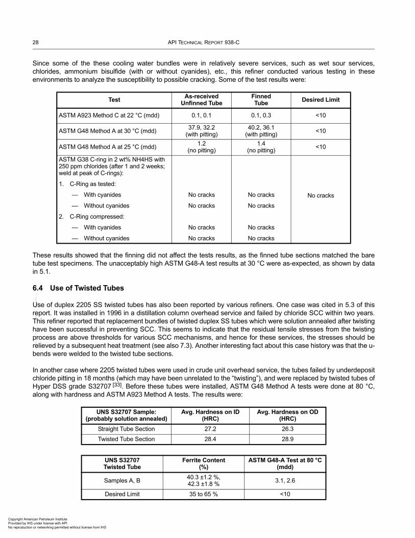
28 API TECHNICAL REPORT 938-C
Since some of the these cooling water bundles were in relatively severe services, such as wet sour services,
chlorides, ammonium bisulfide (with or without cyanides), etc., this refiner conducted various testing in these
environments to analyze the susceptibility to possible cracking. Some of the test results were:
These results showed that the finning did not affect the tests results, as the finned tube sections matched the bare
tube test specimens. The unacceptably high ASTM G48-A test results at 30 °C were as-expected, as shown by data
in 5.1.
6.4 Use of Twisted Tubes
Use of duplex 2205 SS twisted tubes has also been reported by various refiners. One case was cited in 5.3 of this
report. It was installed in 1996 in a distillation column overhead service and failed by chloride SCC within two years.
This refiner reported that replacement bundles of twisted duplex SS tubes which were solution annealed after twisting
have been successful in preventing SCC. This seems to indicate that the residual tensile stresses from the twisting
process are above thresholds for various SCC mechanisms, and hence for these services, the stresses should be
relieved by a subsequent heat treatment (see also 7.3). Another interesting fact about this case history was that the u-
bends were welded to the twisted tube sections.
In another case where 2205 twisted tubes were used in crude unit overhead service, the tubes failed by underdeposit
chloride pitting in 18 months (which may have been unrelated to the “twisting”), and were replaced by twisted tubes of
Hyper DSS grade S32707 [33]. Before these tubes were installed, ASTM G48 Method A tests were done at 80 °C,
along with hardness and ASTM A923 Method A tests. The results were:
TestAs-received
Unfinned TubeFinnedTube
Desired Limit
ASTM A923 Method C at 22 °C (mdd) 0.1, 0.1 0.1, 0.3 <10
ASTM G48 Method A at 30 °C (mdd)37.9, 32.2
(with pitting)40.2, 36.1
(with pitting)<10
ASTM G48 Method A at 25 °C (mdd) 1.2
(no pitting)1.4
(no pitting)<10
ASTM G38 C-ring in 2 wt% NH4HS with 250 ppm chlorides (after 1 and 2 weeks; weld at peak of C-rings):
1. C-Ring as tested:
— With cyanides
— Without cyanides
2. C-Ring compressed:
— With cyanides
— Without cyanides
No cracks
No cracks
No cracks
No cracks
No cracks
No cracks
No cracks
No cracks
No cracks
UNS S32707 Sample:(probably solution annealed)
Avg. Hardness on ID(HRC)
Avg. Hardness on OD (HRC)
Straight Tube Section 27.2 26.3
Twisted Tube Section 28.4 28.9
UNS S32707Twisted Tube
Ferrite Content (%)
ASTM G48-A Test at 80 °C(mdd)
Samples A, B40.3 ±1.2 %,42.3 ±1.8 %
3.1, 2.6
Desired Limit 35 to 65 % <10
Copyright American Petroleum Institute
Provided by IHS under license with API
No reproduction or networking permitted without license from IHS
--`,,,,,`,,,``,`,,,,,,``,```-`-`,,`,,`,`,,`---
USE OF DUPLEX STAINLESS STEELS IN THE OIL REFINING INDUSTRY 29
Other services where duplex 2205 SS twisted tubes have been used include a distillate hydrotreater hot separator
vapor trim cooler and a diesel rundown cooler. These exchangers used welded tube-to-tubesheet joints.
6.5 Duplex SS Castings and HIP Components
Annex D covers typical requirements for DSS castings for items, such as valve bodies and pump cases, in critical
services. Annex D does not cover centrifugally cast line pipe. Annex E covers typical requirements for DSS HIP
components. Some test results showing typical properties of HIP components and applications in the oil and gas
production industry (including subsea) are given in the references [34], [35].
6.6 Duplex SS Used as a Cladding Material
Duplex SS has been used extensively as an explosion-cladding material on carbon steel for applications which do not
require subsequent forming or heat treatment, as the duplex cladding would be degraded by any heat treatments
required on the carbon steel after forming or welding. The most common application is for thick tubesheets and
cladding layers of 8 mm to 19 mm thickness have been used. These applications have included both Standard and
Super DSS grades and have been for numerous different industries.
The full range of DSS cladding thickness applied by the explosion-cladding process has been about 3 mm to 19 mm
to date and there are also cases of titanium cladding being explosively applied to DSS base metal with thicknesses of
25 mm to 152 mm.
7 Fabrication Requirements
7.1 Typical Specification Requirements
In addition to special requirements on the materials, special welding and fabrication requirements are also needed to
ensure proper corrosion and environmental cracking resistance. These requirements are not difficult, they are just
“different” compared to austenitic SSs. Hence, with proper awareness, training and quality control, successful welds
can be achieved. These restrictions are applied in addition to the applicable Code requirements.
The goal of these additional restrictions is to ensure that the fabrication procedures will not significantly diminish the
corrosion resistance, mechanical strength or toughness of the steel. Typical specifications add requirements on the
topics listed in 7.1.1, 7.1.2, 7.1.3, and 7.1.4.
This document previously included examples of specifications for Duplex SS weld procedure qualifications in
Annex B and special production welding requirements in Annex C. These Annexes have been deleted in the Third
Edition of this document, as recent revisions to API 582 address these requirements.
7.1.1 Welding Procedure Qualification (WPS/PQR)
The following are typical specification requirements for WPS/PQR (in addition to applicable Code requirements).
a) Added essential variables for each process;
b) The following additional tests—listing the test methods, sample number and locations, and criteria:
1) ASTM A923 or A1084 (as applicable): Test Method B and/or Test Method C for standard and lean DSSs; and
both tests for 25 % Cr and higher alloys with criteria to be agreed to by purchaser,
2) Microstructure: measurement of intermetallics and percent ferrite from point count (see 7.4),
3) hardness survey; and
c) Qualification of critical repair welds with a partial penetration joint detail (and consideration of cumulative heat
implications).
Copyright American Petroleum Institute
Provided by IHS under license with API
No reproduction or networking permitted without license from IHS
--`,,,,,`,,,``,`,,,,,,``,```-`-`,,`,,`,`,,`---

30 API TECHNICAL REPORT 938-C
7.1.2 Welding
The following are typical specification requirements for welding (in addition to applicable Code requirements):
a) cutting and joint preparation restrictions;
b) welding process restrictions;
c) a list of acceptable filler metals (including permissible over-alloyed and nickel-based filler metals);
d) the maximum and minimum heat input;
e) a maximum interpass temperature;
f) GTAW root passes for single-sided welds with filler addition and cold-pass technique (thin gauge material [less
than about 3 mm] can be welded without filler metal);
g) the backing and shielding gas compositions;
h) heat tint removal on the process side, when accessible;
i) removal of arc strikes (arc strikes should be on the previous run [preferably] or in the joint).
7.1.3 Tube-to-tubesheet Joints
The following are typical specification requirements for tube-to-tubesheet joints:
a) some users: prohibition of rolled joints, except light rolling (<2 %) for positioning (due to possible high hardness)
and requirement of strength welds with filler metal;
b) other users: allowance of rolled joints or rolled and welded joints with prequalification mockup tests, including
hardness testing;
c) if welding, requirement of mockup and other tests as part of WPS/PQR.
7.1.4 NDE of Production Welds
The following are typical specification requirements for NDE of production welds (in addition to applicable Code
requirements):
a) PT of backgouging;
b) PT of completed welds;
c) percent ferrite measurement, with feritscope and calibration to AWS A4.2;
d) code-required NDE with added RT of high pressure and other critical welds.
7.2 Typical Welding Processes and Filler Metals
The acceptable welding processes include GTAW, SAW, GMAW, SMAW and FCAW (see 4.4). Commonly used filler
metals are shown in Table 9. Even though the weld filler metals used for welding of standard duplex SS grade 2205
has higher nominal nickel content (9 %) than the base metal (5 % nominal), they are often referred to as
“matching”.
Copyright American Petroleum Institute
Provided by IHS under license with API
No reproduction or networking permitted without license from IHS
--`,,,,,`,,,``,`,,,,,,``,```-`-`,,`,,`,`,,`---

USE OF DUPLEX STAINLESS STEELS IN THE OIL REFINING INDUSTRY 31
7.3 Dissimilar Metal Welding
For dissimilar metal welding, it is generally possible to weld DSSs to carbon steel, alloy steels, austenitic SS, and
other grades of DSSs (although PWHT requirements need to be considered). The important points to note in
selecting the filler metal are to obtain a weld metal with strength and corrosion resistance superior to at least one of
the dissimilar metals, and to achieve a phase balance that will ensure a mechanically tough weld. A duplex filler metal
is generally used for welded joints between DSSs and CS or austenitic SS, but austenitic SS filler metals have also
given satisfactory results. Examples of these DSSs filler metals are indicated for 22 % Cr and 25 % Cr DSSs in Table
9. Manufacturer’s recommendations are typically followed when welding DSSs to other alloys, along with the
recommendations in API 582.
When welding DSSs to carbon or alloy steels, consideration is usually given to the potential detrimental effects on the
DSS of the preheating or PWHTs required by the carbon or alloy steel. Preheating may slow the cooling of the DSS
HAZ enough that intermetallic phases form. Most PWHTs for steel will lead to formation of intermetallic phases in
DSSs. It may not always be possible to weld DSS to carbon or alloy steel and have both sides of the weld in an
optimal metallurgical condition. One solution is to butter the CS or low alloy with austenitic filler metal (e.g. E309L),
PWHT and then weld to the DSS using a DSS filler metal.
In some cases, Ni-based filler metals are proposed for either dissimilar metal welds or duplex welds. However, Ni-
based fillers may give rise to a fully ferritic zone adjacent to the fusion line in DSS, which would not meet the desired
ferrite requirement. This zone tends to give reduced toughness of the weldment. There can also be intermetallic
phases formed in the weld metal, resulting in reduced corrosion resistance. Nickel-based filler metals containing
niobium (Nb) have reportedly resulted in low weld metal toughness and solidification cracking and should be avoided,
but other high Cr, high Mo nickel-based filler metals (with <0.5 Nb) have been used successfully, such as ENiCrMo-4,
ENiCrMo-10, ENiCrMo-13, and ENiCrMo-14.
7.4 Ferrite Measurements vs. Austenite Spacing
Achieving the proper phase balance in weld deposits and heat affected zones is a critical concern during welding and
is verified by ferrite measurements done on the weld procedure qualification samples. Although ferrite measurements
in various areas of the microstructure using the ASTM E564 point count method are difficult and the accuracy
between laboratories has been poor, no better test has yet been devised. Another test method measures “austenite
spacing” and is referenced within one other industry standard for thick wall components (>25 mm). However, the
results of a test program using this method were recently presented at NACE and this testing showed that the
austenite spacing test is not valid for verifying the proper phase balance [36].
When obtaining ferrite measurements with the ASTM E564 manual point count testing method, an experienced
laboratory should be used. One expert reported that doing an electrolytic etch in 10 % oxalic, prior to the NaOH or
Table 9—Welding Consumables
Process 22 % Cr 25 % Cr (Note 1) 27 % Cr
SMAW SFA 5.4 E2209 SFA 5.4 E2553, E2594, or E2595 Not applicable
GTAW/GMAW SFA 5.9 ER2209 SFA 5.9 ER2553, or ER2594 As recommended by alloy supplier
SAWSFA 5.9 ER2209 with a flux designed for DSSs
SFA 5.9 ER2594 with a flux designed for DSSs
As recommended by alloy supplier
FCAW SFA 5.22 E2209TX-X or EC2209SFA 5.22 E2553TX-X, E2594TX-X, EC2553, or EC2594
Not applicable
NOTE This table does not cover some of the specialized 25 % Cr alloys. The material manufacturer’s (i.e. the alloy supplier’s) recommendations on welding consumables should be followed.
Copyright American Petroleum Institute
Provided by IHS under license with API
No reproduction or networking permitted without license from IHS
--`,,,,,`,,,``,`,,,,,,``,```-`-`,,`,,`,`,,`---

32 API TECHNICAL REPORT 938-C
KOH etch, results in the phases standing out better (oxalic clearly shows the phase boundaries and any nitrides,
which will not show with caustic etching alone).
The automatic image analysis techniques in ASTM E1245 are not yet developed with the necessary procedure
details for the purpose of determining the ferrite content in DSS wrought materials and weldments.
7.5 Cold Working and Hot and Cold Bending
Solution annealing is generally required by Code or purchaser specifications after cold work exceeds 10 %
deformation for 22 % Cr DSSs and on all cold worked or bent (hot or cold) components of 25 % Cr DSSs (except on
heat exchanger U-bends). If the cold deformation will exceed 15 %, an intermediate anneal may also be required.
This applies to tube and pipe cold bending and other cold forming operations. Except for the issues regarding
avoidance of SSC, higher limits might reasonably be considered if the fabrication equipment is capable of dealing with
high-strength DSSs.
Heat exchanger U-bends are difficult to heat treat without some zone of the tubes being exposed to an unacceptable
temperatures, which results in impaired corrosion resistance. With furnace heat treatments, which typically only have
the bends inserted into the furnace, the tangent lengths can be exposed to an unacceptable temperature. In addition,
testing has shown that the properties of the U-bends without heat treatment are acceptable for refinery services down
to bend radiuses of 1.5 times the tube diameter for super DSSs grades and at least 3.3 times the tube diameter for
S32205. Hence, various users have concluded that no heat treatment of U-bends should be specified, as long as
there is a 3.3D minimum radius for 2205 DSS (the inner row of tubes can be installed with the U-bend diagonal and
with a few less tubes to accommodate this larger minimum radius) [37].
In the cases where heat treatment of U-bends is specified, resistance or capacitance heating has been used
successfully with procedures carefully designed to minimize the time of tube exposure to the 700 °C to 950 °C
(1300 °F to 1750 °F) range.
Hot bending of piping is generally done using the induction bending process and the procedures are qualified with test
bends and various essential variables. The bending temperature for 22 % Cr is typically in the range of 1000 °C to
1066 °C (1830 °F to 1950 °F). During induction bending, DSS pipe is purged with nitrogen or argon (0.5 % maximum
oxygen). Bends produced from 22 % Cr DSS are solution annealed, if needed, to meet the required mechanical
properties. After final heat treatment of any DSS bend, a chemical descaling and neutralization treatment is typically
done. Any longitudinal welds normally receive 100 % RT after bending and the bend surface typically receives 100 %
PT. Dimensional and hardness testing are also performed.
7.6 Tube-to-tubesheet Joints
Tube-to-tubesheet welded joints can be prone to high hardness due to rapid cooling and tube-to-tubesheet rolled
joints can be prone to high hardness due to the cold work. This is a concern since many DSS heat exchangers and air
coolers used in refining are primarily in relatively severe wet sour services where high hardness (approximately
>320 HV for LDSS or DSS and >350 HV for SDSS) would be unacceptable. For shell-and-tube exchangers, the
preferred type of tube-to-tubesheet joint is determined on a case-by-case basis. Strength welding with light rolling
only (<2 %) has been used for wet sour services, or a rolling procedure that results in acceptable hardness for the
specific material grade and exchanger design have been used. To test the tube-to-tubesheet joint acceptability,
whether it is welded, rolled or welded and rolled, a mock-up is often required to prequalify the procedure.
Over-alloying of these welds (which are generally made with the GTAW process), such as with ER2509 or Ni-based
(Nb free) filler metal, can also be considered in order to help provide a better HAZ phase balance, even with the
inherent low heat input. Another option for alloy 2205 DSS tube-to-tubesheet joints is to use alloy 309Mo or 309LMo
SS GTAW filler metal with argon-2 % nitrogen shielding gas when an austenitic weld is acceptable for the service.
The nitrogen in the gas and the higher nickel content in the filler metal give a better phase balance in the HAZs of
these low heat input joints. Some users require argon-2 % nitrogen shielding gas for matching filler metals also.
Copyright American Petroleum Institute
Provided by IHS under license with API
No reproduction or networking permitted without license from IHS
--`,,,,,`,,,``,`,,,,,,``,```-`-`,,`,,`,`,,`---

USE OF DUPLEX STAINLESS STEELS IN THE OIL REFINING INDUSTRY 33
When rolled joints are used, seamweld tubing root penetration needs to be considered. Some users specify
beadworking for seamwelded DSS tubing, as discussed in 6.2. Rolled joints for less severe services (e.g. most
cooling water and non-wet sour hydrocarbons) can be used with less precaution to minimize the risk of high
hardnesses. Also, one test program with various degrees of rolling and rolled joints, with and without welding, did not
show any of the rolls to have unacceptably high hardnesses [38].
In some severe services removal of the crevice to prevent corrosion from the shell-side service may be needed.
When the shell-side service is seawater, some exchangers have been fabricated with crevice-free backface welding
techniques that involve seal welding of the tubes on the backside of the tubesheet.
For the mock-up used to prequalify the tube-to-tubesheet welding and/or rolling procedures, ASME Section IX, QW-
193 is generally followed with additional special requirements. The assembly of the mock-up is typically required to
simulate all steps of the production joint, including both welding and rolling. In addition, if production welding is to be
performed through the plug sheet, this should be simulated in the test assembly. Past testing has specified that the
access hole diameter and distance from hole to tubesheet shall be equal to production distances ±10 %. For testing,
in addition to the macro-examination required by ASME Section IX, QW-193, the microstructure, microhardnesses
and ferrite contents of one randomly selected weld section is typically analyzed (both in the weld and HAZs). In some
cases, for standard and SDSS grades, a quadrant section of a tube-to-tubesheet weld may also be subject to
corrosion testing with no pitting allowed.
7.7 Post-Fabrication Cleaning
The main objectives of post-fabrication cleaning are to:
— remove significant welding heat tints;
— remove weld spatter, flux, slag or arc strikes;
— remove surface contamination from smeared or embedded iron;
— remove surface contamination from dirt, oil, paint or crayon marks;
— ensure there is an adherent, continuous, protective, chromium-rich oxide layer on the entire surface.
Weld spatter, flux, slag, arc strikes, and some weld heat tints can be removed by mechanical cleaning, such as fine
abrasive grinding or with a stainless steel wire wheel or brush. A “fine” grinding wheel is typically used, as coarse
grinding marks can be another source of disruption of the protective passive oxide layer by allowing deposits to stick
to the surface. For removal of heat tints and other contaminants the order of efficiency of the cleaning methods is:
— blasting,
— grinding,
— pickling and passivation,
— electropolishing.
The best corrosion resistance is obtained by mechanical cleaning followed by chemical pickling and passivation [39].
7.8 NDE Methods
For Code-required NDE of welds, RT is relatively straightforward for DSSs and standard techniques can be used.
However, UT requires specialized techniques due to the anisotropic nature and relatively large grains of DSS
welds [2].
Copyright American Petroleum Institute
Provided by IHS under license with API
No reproduction or networking permitted without license from IHS
--`,,,,,`,,,``,`,,,,,,``,```-`-`,,`,,`,`,,`---

34 API TECHNICAL REPORT 938-C
7.9 Hydrostatic Testing
Some specifications limit the chloride content of hydrotest water to 50 ppm, similar to austenitic SSs, to minimize the
risk of chloride pitting or SCC during startup. However, other users consider that with the demonstrated resistance of
UNS S32205 to much higher levels of chloride and higher temperatures in long-term service, this limit is
unnecessarily conservative and costly. In any case, particular attention should also be given to drying of the
equipment after hydrostatic testing in order to minimize the risk of microbiologically influenced corrosion (MIC).
7.10 Coating Requirements and Risk of CUI
Duplex SS components which are insulated and in an area where the climate or atmospheric conditions and the
operating temperature range create a risk of external corrosion or chloride SCC due to CUI (see 5.1 of this report),
are typically externally protected in a similar manner as austenitic SS. NACE SP0198 addresses this concern and
gives recommended protection systems. Non-insulated DSSs are typically not coated as they have excellent
atmospheric corrosion resistance.
8 Examples of DSSs Applications within Refineries
Numerous data sources were reviewed to compile a list of past uses of DSSs within refineries. One source that
provided many case histories was NACE International’s Refin-Cor database. Refin-Cor is a compilation of
approximately 50 years of meeting minutes from the Refining Industry Corrosion Group. Table 10 shows the results of
a search within this database. The item number is the paragraph identifier within the minutes and the first two digits
indicate the year the item was presented. Table 11 shows other case histories from various published and
unpublished sources, such as DSS material suppliers’ case history reports and published literature primarily from
users.
A list of the applications and the corresponding corrosion or other failure mechanisms that led to the selection of DSS
is shown in Table 12. However, users are cautioned that in some services standard duplex grades may be inadequate
and higher DSS grades are preferred. Failures have occurred under some conditions, as listed in Table 10. Also,
failures can occur in almost all services if DSS is of poor material quality or is improperly fabricated.
Copyright American Petroleum Institute
Provided by IHS under license with API
No reproduction or networking permitted without license from IHS
--`,,,,,`,,,``,`,,,,,,``,```-`-`,,`,,`,`,,`---

USE OF DUPLEX STAINLESS STEELS IN THE OIL REFINING INDUSTRY 35Tab
le 1
0—
Case H
isto
ries o
f D
SS
Uses R
ep
ort
ed
in
NA
CE
In
tern
ati
on
al R
efi
n-C
or
Item
No
.U
nit
Serv
ice
Gra
de
Pro
ble
ms
Co
mm
en
ts
02F
5.1
9-3
6A
min
eM
EA
Recla
imer
2205
None
Repla
ced 3
00 s
eries S
S w
hic
h s
uffere
d C
l S
CC
08C
4.2
4-1
1A
min
eM
EA
Recla
imer
2205
Pitting in e
nds o
f U
-bends (
150 m
m
length
s)
due to im
pro
per
heat
treatm
ent. R
em
ain
der
of tu
be “
work
ing
very
well”
.
No longer
usin
g h
eat tr
eatm
ent of D
SS
s U
-bends
97F
5.4
-01
Coker
Fra
ctionato
r overh
ead
condenser
2205
Isola
ted p
itting o
n p
rocess s
ide a
fter
four
years
Both
base m
eta
l and w
eld
. O
n ferr
ite n
ot
auste
nite
03C
5.4
-01
Coker
Fra
ctionato
r overh
ead
condensers
2205
None
Repla
ced 7
0-3
0 C
u-N
i whic
h h
ad a
six
-year
life
and faile
d b
y c
orr
osio
n a
nd/o
r denic
kelif
ication.
Costs
were
the s
am
e
90F
9.1
6-4
0C
oolin
g W
ate
r>
250 °
F o
n p
rocess s
ide
2205
None
Exam
ple
s: F
CC
fra
ctionato
r overh
ead a
nd
vacuum
overh
ead c
ondenser
02F
5.1
7-0
1C
oolin
g W
ate
rF
resh w
ate
r re
circula
ted C
W
exchangers
at th
ree r
efin
eries
2205
None. H
ave n
ot fo
und p
ractical m
ate
rial
for
floating h
eads y
et (u
sin
g c
oate
d C
S
or
316 S
S to d
ate
).
Weld
ed D
SS
s tubes w
as found to b
e c
ost
com
para
ble
to b
rass a
nd r
eadily
availa
ble
08C
4.1
6-1
0C
oolin
g W
ate
rC
ritical b
undle
s in
fre
sh w
ate
r C
W s
erv
ice
2205
None
Repla
cin
g C
S b
undle
s that w
ere
not la
sting for
two r
uns
08C
4.1
6-1
7C
oolin
g W
ate
rN
um
ero
us b
undle
s in fre
sh
wate
r C
W s
erv
ice
2205
None
Recently d
id inte
rnal surv
ey; no s
igns o
f M
IC;
good s
erv
ice; re
pla
ce C
S tubes (
reusin
g C
S
tubesheets
) re
gula
rly; cost is
about tw
ice
com
pare
d to u
sin
g C
S tubes
80C
5.2
-04
Cru
de
Overh
ead c
ondenser
and
desalter
efflu
ent exchanger
3R
E60
One m
anufa
ctu
ring p
roble
m
80C
5.2
-05
Cru
de
Desalter
efflu
ent exchanger
and top P
/A e
xchanger
3R
E60
OK
in d
esalter efflu
ent; faile
d faste
r th
an
CS
in top P
/A d
ue to h
ot chlo
ride p
itting
80C
5.2
-06
Cru
de
Overh
ead
3R
E60
None
Test tu
be; show
ed 2
mpy to 3
mpy
87F
7.1
-13
Cru
de
Overh
ead c
ondenser
3R
E60
Faile
d b
y S
SC
in a
few
month
sTest tu
bes
89C
7.2
-09
Cru
de
Tow
er
top lin
ing
2205
None
Pre
vio
us s
ulfur
corr
osio
n o
f M
onel due to
incre
asin
g tem
pera
ture
to >
250 °
F
89F
9.2
-05
91C
9.1
-01
Cru
de
Vacuum
overh
ead c
ondenser
2205
None
Went to
2205 d
ue to foulin
g p
roble
ms o
n C
S;
not corr
osio
n
Copyright American Petroleum Institute
Provided by IHS under license with API
No reproduction or networking permitted without license from IHS
--`,,,,,`,,,``,`,,,,,,``,```-`-`,,`,,`,`,,`---

36 API TECHNICAL REPORT 938-C
92C
5.1
-16
Cru
de
Instr
um
ent tu
bin
g2304
None
Repla
ced 3
16 S
S that fa
iled b
y S
CC
97F
5.1
-06
Cru
de
Tow
er
inte
rnals
SC
C d
ue to h
ot caustic
Als
o c
racked 3
16 S
S a
nd c
orr
oded 4
10 S
S
98F
5.2
-24
99C
5.2
-01
Cru
de
Fra
ctionato
r overh
ead
condenser
2205
Som
e p
itting a
nd fatigue
(Late
r re
pla
ced d
ue to w
ear
at enla
rged b
affle
hole
s)
00F
5.2
-34
Cru
de
Tow
er
packin
g in top p
um
p-
aro
und a
rea
DS
Ss
None
Repla
ced M
onel, w
hic
h c
orr
oded d
ue to
evapora
ting s
our
wate
r and d
eposited s
alts
01F
5.2
-45
Cru
de
Fra
ctionato
r overh
ead
condenser
2205/2
507
2205 c
orr
oded a
nd w
as r
epla
ced w
ith
2507. S
hock c
ondensation
Repla
ced ferr
itic
SS
whic
h e
ventu
ally
corr
oded
01F
5.2
-46
Cru
de
Fra
ctionato
r to
wer cla
ddin
g in
to
p s
ection
2205
Did
well
min
or
pitting w
hic
h d
id n
ot
affect serv
iceabili
tyC
S h
ad c
orr
oded thro
ugh
98C
5.2
-10
Cru
de/B
itum
en
Fra
ctionato
r overh
ead
condenser
2205 tw
iste
d
tube
None
OK
after
one y
ear. F
oulin
g s
erv
ice
77F
6.3
-01
FC
C L
ight E
nds
Slu
rry/s
plit
ter
feed
3R
E60
None
Test tu
bes
98F
5.5
-02
FC
CU
Lig
ht ends r
eboile
rN
one
Str
ess r
elie
ved U
-bends, pic
kle
d. T
hey b
elie
ve
pic
klin
g p
rovid
es a
good p
assiv
e film
98F
5.5
-04
FC
CU
Dilu
ent re
covery
unit
2205 tw
iste
d
tube
Faile
d d
ue to C
SC
C a
t re
sid
ual str
ess
pattern
s in the tubes (
from
both
sid
es?)
Overh
ead is a
cid
ic d
ue to C
l and n
eutr
aliz
ed
with a
mm
onia
. A
lso C
W h
as s
ignific
ant C
l
85C
9.2
-01
H2S
O4 A
lky
DIB
overh
ead c
ondenser
3R
E60
Faile
d d
ue to flu
oride d
eposits
(10 %
to
15 %
F
)F
luorides in p
urc
hased feedsto
cks. W
ent to
S
anic
ro 2
8
10C
4.1
9-0
1F
lare
Gas
Recovery
Unit
Coker
flare
gas r
ecovery
liq
uid
rin
g c
om
pre
ssor
impelle
r
Cast duple
x
SS
None
Pre
vio
us c
ast 316 S
S im
pelle
r fa
iled b
y
chlo
ride S
CC
. T
hey h
ave n
um
ero
us fla
re g
as
recovery
liquid
rin
g c
om
pre
ssors
made o
f D
SS
.
98F
5.8
-01
HD
SR
EA
C3R
E60
CS
CC
under
deposits
At 300 °
F to 4
00 °
F w
here
deposits
colle
cte
d
98F
5.8
-02
HD
SE
xchanger
2205
SC
C u
nder
NH
4C
l deposits
Rest of exchanger
was in p
ristine c
onditio
n
97C
5.8
-08
HD
SS
trip
per
overh
ead a
ir c
oole
r2205
None
Surv
ey—
als
o p
ipin
g a
nd c
laddin
g in tow
er
top
89C
7.6
-06
96C
5.1
0-0
9H
DS
RE
AC
3R
E60
Exte
nsiv
e h
eader
weld
cra
cks fro
m
fabrication
Used C
S a
s a
tem
pora
ry r
epla
cem
ent
91C
9.7
-01
HD
SS
trip
per fr
actionato
r to
wer to
p
cla
ddin
g2205
None
Pre
vio
us N
H4H
S/N
H4C
l corr
osio
n o
n 3
09
overlaid
CS
in o
ne y
ear. A
t 250 °
F to 2
80 °
F
Tab
le 1
0—
Case H
isto
ries o
f D
SS
Uses R
ep
ort
ed
in
NA
CE
In
tern
ati
on
al R
efi
n-C
or
(Continued)
Item
No
.U
nit
Serv
ice
Gra
de
Pro
ble
ms
Co
mm
en
ts
Copyright American Petroleum Institute
Provided by IHS under license with API
No reproduction or networking permitted without license from IHS
--`,,,,,`,,,``,`,,,,,,``,```-`-`,,`,,`,`,,`---

USE OF DUPLEX STAINLESS STEELS IN THE OIL REFINING INDUSTRY 37
96C
5.1
0-0
3H
DS
RE
AC
2205
None—
recently insta
lled
8 %
NH
4H
S; 25 fps to 3
0 fps
96C
5.1
0-0
6H
DS
RE
AC
2205
None
OK
after
four
years
. A
t H
usky O
il. 4
.9 %
N
H4H
S
96C
5.1
0-0
7H
DS
RE
AC
Refe
rred to C
orr
osio
n/9
7 p
aper
whic
h inclu
des
successes a
nd failu
res
96C
5.1
0-0
8H
DS
RE
AC
Pro
duction p
aper
dis
cusses h
ydro
gen u
pta
ke
from
galv
anic
couple
96C
5.1
0-1
1H
DS
Last efflu
ent exchangers
3R
E60
None
OK
after
17 y
ears
. A
noth
er
bundle
in h
otter
serv
ice faile
d b
y 8
85 °
F e
mbrittle
ment
(opera
ting tem
pera
ture
≥600 °
F)
00F
5.8
-12
HD
SR
EA
C o
utlet pip
ing
2205
None
Repla
ced c
orr
oded C
S. N
H4H
S is
8 %
to 1
0 %
, w
ith 1
8 fps to 2
0 fps a
nd w
ate
r w
ash
04F
5.7
-31
HD
SR
EA
C2205
None. 2205 tubes in C
S h
eader
boxes.
Als
o in c
at fe
ed H
DS
and h
ydro
cra
cker
Tubes w
ere
seal w
eld
ed to h
eader
box. In
one
case, th
e C
S h
eader
suffere
d n
ozzle
corr
osio
n
due to N
H4H
S
86F
7.3
-02
HD
S—
Cat F
eed
Feed/e
fflu
ent (?
)3R
E60
Good
CS
CC
of auste
nitic
SS
. Test tu
bes
73F
8.4
-01
Hydro
gen P
lant
ME
A r
eboile
r3R
E60
None
Pre
vio
us S
CC
of 304 S
S w
ith 1
000 p
pm
Cl
97C
5.7
-03
Hydro
gen P
lant
Pot. c
arb
onate
CO
2 r
em
oval
reboile
r2507
None
OK
after 5 y
ears
. R
epla
ced c
orr
oded C
S. U
sed
weld
ed tube to T
S join
ts
86F
7.3
-03
Hydro
cra
cker
Reacto
r efflu
ent/str
ipper
feed
3R
E60
Cra
cked b
y S
CC
in four
month
s fro
m
str
ipper
feed s
ide
Mechanis
m n
ot defined. C
oncern
ed w
ith h
igh
H2S
and c
hlo
rides
87F
7.3
-04
Hydro
cra
cker
Fra
ctionato
r fe
ed/r
eacto
r efflu
ent
2304
None.
Repla
ced 3
04S
S, w
hic
h faile
d in
four years
due
to C
SC
C fro
m r
eacto
r efflu
ent
94C
5.8
-01
Hydro
cra
cker
Feed/e
fflu
ent exchangers
(2
nd s
tage)
3R
E60
Faile
d—
CS
CC
fro
m O
D a
nd h
ydro
gen
cra
ckin
g fro
m ID
96C
5.9
-06
Hydro
cra
cker
CW
at 150 °
F2205
None
OK
after
two y
ears
. R
epla
ced S
S that fa
iled b
y
SC
C a
t a U
-bend
85C
14.8
-03
Pip
elin
eC
onta
inin
g w
et C
O2
2205
None
17 m
iles; cheaper
than 3
16L
85C
14.8
-06
Pip
elin
eU
nder
desig
n; in
Ala
ska; did
an e
conom
ic
stu
dy
Tab
le 1
0—
Case H
isto
ries o
f D
SS
Uses R
ep
ort
ed
in
NA
CE
In
tern
ati
on
al R
efi
n-C
or
(Continued)
Item
No
.U
nit
Serv
ice
Gra
de
Pro
ble
ms
Co
mm
en
ts
Copyright American Petroleum Institute
Provided by IHS under license with API
No reproduction or networking permitted without license from IHS
--`,,,,,`,,,``,`,,,,,,``,```-`-`,,`,,`,`,,`---

38 API TECHNICAL REPORT 938-C
99F
5.1
6-0
4S
team
Gen.
Ste
am
genera
tor
with s
our
wate
r on o
ther
sid
e2205
None
79C
9.1
-04
SW
S
Feed/b
ottom
s3R
E60
None
AP
I S
urv
ey r
esult
79F
9.1
-01
SW
SR
eboile
r3R
E60
None
Test tu
bes
80F
11.1
-05
SW
SR
eboile
r3R
E60
Faile
d in less than a
year
Gas p
lant
86C
11.2
-01
SW
SS
trip
per
overh
ead
3R
E60
Good a
fter
18 m
onth
sP
revio
us p
roble
ms w
ith C
S, 304S
S, In
conel
600 a
nd T
i
86F
7.1
0-0
2S
WS
Str
ipper
overh
ead
3R
E60
None
88C
7.1
0-0
3S
WS
Reboile
r2205
Faile
d b
y u
nder-
deposit p
itting a
fter
thre
e to four
years
88C
7.1
0-0
4S
WS
Reboile
rs a
nd feed/b
ottom
s
exchanger
3R
E60
None
OK
after
15 y
ears
88C
7.1
0-0
6S
WS
Overh
ead a
ir c
oole
r and
feed/b
ottom
s e
xchanger
3R
E60
None
OK
after
thre
e to four
years
95C
5.5
-06
SW
SS
trip
per
overh
ead
2205
None
95C
5.5
-20
SW
SS
trip
per
overh
ead
2205
None
96F
5.1
2-0
2S
WS
Reboile
r2205
None
Corr
osio
n o
f C
S. 316 a
lso a
ccepta
ble
05C
5.1
1-0
1S
WS
Pip
ing
2205
None
Repla
ced h
ydrided T
i
05C
5.1
1-0
3S
WS
Overh
ead e
xchanger
2205
Faile
d a
fter
thre
e m
onth
s d
ue to
pre
fere
ntial attack o
f th
e a
uste
nitic
phase
Repla
ced a
lum
inum
whic
h faile
d a
fter
18
month
s d
ue to e
rosio
n
Tab
le 1
0—
Case H
isto
ries o
f D
SS
Uses R
ep
ort
ed
in
NA
CE
In
tern
ati
on
al R
efi
n-C
or
(Continued)
Item
No
.U
nit
Serv
ice
Gra
de
Pro
ble
ms
Co
mm
en
ts
Copyright American Petroleum Institute
Provided by IHS under license with API
No reproduction or networking permitted without license from IHS
--`,,,,,`,,,``,`,,,,,,``,```-`-`,,`,,`,`,,`---

USE OF DUPLEX STAINLESS STEELS IN THE OIL REFINING INDUSTRY 39Tab
le 1
1—
Case H
isto
ries o
f D
SS
s U
ses R
ep
ort
ed
by O
ther
So
urc
es
Un
itG
rad
eTu
be-
sh
eet
Mate
rial
Sh
ell-s
ide S
erv
ice
Sh
ell
Tem
p.
In/O
ut
(°F
)
Sh
ell
Pre
ssu
re(p
si)
Tu
be-s
ide S
erv
ice
Tu
be
Tem
p.
In/O
ut
(°F
)
Tu
be
Pre
ssu
re
(psi)
Co
mm
en
ts
Am
ine
2205
—0.1
3 m
ole
% H
2S
, 0.9
mole
% H
2O
237/1
15
87
CW
with 6
00 to 1
000
Cl, c
hro
mate
s inhib
.86/9
190
Sta
rted s
erv
ice in 1
983
Am
ine
2205
304 S
SA
min
e, C
O2,
cyanid
e, N
H3, H
2S
, poly
sulp
hid
es
——
Ste
am
——
Deliv
ere
d in 1
987. U
-bends. C
S
faile
d.
Note
1
Am
ine
2205
2205
(F51)
Heating m
ediu
m284/2
12
309
Ric
h M
DE
A, C
O2
160/1
65
196
CO
2 rem
oval p
lant, ric
h a
min
e h
eate
r,
seven y
ears
good s
erv
ice to d
ate
. T
ubes s
ee 1
3.7
fps. E
xpanded a
nd
str
ength
weld
ed
Cru
de
2205
CS
AP
S o
verh
ead
312/2
40
11
Undesalted c
rude feed
121/2
40 -
series
417
Tw
o b
undle
s. O
nly
bottom
half
Cru
de
2205
CS
Wet naphth
a (
OH
)240/1
10
(fro
m A
/C)
8C
W—
—Tw
o b
undle
s
Cru
de
2205
—
Waste
wate
r—1000 p
pm
m
axim
um
Cl, 5
000 p
pm
m
axim
um
H2S
, about 3
00
ppm
NH
3
104/1
94
—D
esalter
Eff. W
ate
r—6000 p
pm
maxim
um
C
l257/1
40
—In
sta
lled in 1
984
Cru
de
2205
—A
ir—
—D
esaltin
g—
15 %
mole
fr
act. C
O2, 2 p
pm
to 5
ppm
HC
l, 2
ppm
H2S
221
250
In s
erv
ice s
ince 1
982
Cru
de
2205
—S
team
203/1
94
145
Cru
de o
il68/1
40
362
Four
bundle
s—
Insta
lled in 1
983
Cru
de
2507
2507
Naphth
a p
um
p-a
round,
wate
r, c
hlo
ride s
alts
——
CW
——
The tubes h
ad e
xte
nsiv
e C
SC
C o
n
the O
D a
fter
appro
xim
ate
ly o
ne y
ear
Coker
Dupl.
CS
Overh
ead c
om
pre
ssor
inte
rsta
ge
250
a/1
05
37
CW
——
Tw
o b
undle
s. C
hannel coate
d w
ith
epoxy p
henolic
Coker
Dupl.
CS
Overh
ead c
om
pre
ssor
after
coole
r250/1
05
(Note
2)
145
CW
——
Tw
o b
undle
s. C
hannel coate
d w
ith
EP
; S
hell
304 S
S c
lad
Dis
tilla
tion
2205
—G
asolin
e w
ith s
ulp
hur
A: 192/2
19
B: 205/2
55
—H
ydro
carb
ons, w
ate
r,
som
e c
hlo
rides
A: 302/
219
B: 349/
273
—O
rdere
d in 1
984. C
S laste
d tw
o y
ears
Copyright American Petroleum Institute
Provided by IHS under license with API
No reproduction or networking permitted without license from IHS
--`,,,,,`,,,``,`,,,,,,``,```-`-`,,`,,`,`,,`---

40 API TECHNICAL REPORT 938-C
FC
CU
2205
CS
w/3
04L
SS
cla
dF
ractionato
r overh
ead
240
a/1
00
5C
W—
—E
ighte
en b
undle
s. S
hell
SS
cla
d a
lso
on B
, D
, F
FC
CU
2205
CS
w/
Belz
ona
Cat gas
238/1
00
40
CW
——
Four
bundle
s. 2205 insta
lled in 6
/98
FC
CU
2205
—G
as fro
m F
CC
dis
tilla
tion
238/1
26
—T
reate
d w
ate
r68 to 9
9/
201 to 2
20
—In
sta
lled in 1
988. C
S laste
d s
ix y
ears
Hydro
-cra
cker
2205
—A
ir—
—G
as w
ith 6
% H
2O
, 0. 1
6 %
NH
3, 77 %
H2,
3.1
H2S
266/1
22
1740
In s
erv
ice s
ince 1
983
Hydro
de-
sulfurization
2205
—B
FW
221/3
90
—P
rocess g
as
725/3
74
Ord
ere
d in 1
985
Hydro
de-
sulfurization
2205
—G
asoil,
H2O
, N
H4H
S
(30 %
)285/3
40
285
Ste
am
645/5
70
320
Insta
lled 1
987. C
S laste
d thre
e y
ears
Hydro
de-
sulfurization
(AR
DS
)
3R
E60/
2205
CS
/2205
Air
——
HH
PS
Overh
ead, hig
h
NH
4H
SN
ot
report
ed
Not
report
ed
Orig. C
S h
eaders
and 3
RE
60 tubes.
CS
nozzle
s. O
utlet dow
ncom
ers
corr
oded leak/fire in fiv
e to s
ix y
ears
. R
epla
ced w
ith 2
205 in 1
981. T
ubes
were
0.0
65 in. m
inim
um
. N
ow
many
are
clo
se to t
min
of 0.0
50 in. (0
.5 m
py
to 0
.7 m
py).
Som
e tubes h
ave b
een
plu
gged.
Hydro
-pro
cessin
g2205
2205
Air
——
Reacto
r efflu
ent
—2300
SS
C o
f m
ultip
le tube-t
o-t
ubesheet
weld
s s
hort
ly a
fter
Jan. 2002 s
tart
up
– s
om
e w
ithin
48 h
ours
. S
om
e w
eld
s
confirm
ed to h
ave h
igh ferr
ite (
see
Refe
rence 2
3).
Hydro
-pro
cessin
g2205
2205
Air
——
Reacto
r efflu
ent; 3
.8
wt.%
NH
4H
S in s
ep.
—1200
Nov.
2003. C
racked p
ipe w
eld
at
RE
AC
outlet; c
rackin
g w
ithin
weld
; w
eld
hard
ness a
nd ferr
ite w
ere
accepta
ble
. 1.2
5 in. of pip
e s
pring-
back a
t fa
ilure
location. 5 y
ears
of
serv
ice (
see R
efe
rence 2
3).
Tab
le 1
1—
Case H
isto
ries o
f D
SS
s U
ses R
ep
ort
ed
by O
ther
So
urc
es (
Continued)
Un
itG
rad
eTu
be-
sh
eet
Mate
rial
Sh
ell-s
ide S
erv
ice
Sh
ell
Tem
p.
In/O
ut
(°F
)
Sh
ell
Pre
ssu
re(p
si)
Tu
be-s
ide S
erv
ice
Tu
be
Tem
p.
In/O
ut
(°F
)
Tu
be
Pre
ssu
re
(psi)
Co
mm
en
ts
Copyright American Petroleum Institute
Provided by IHS under license with API
No reproduction or networking permitted without license from IHS
--`,,,,,`,,,``,`,,,,,,``,```-`-`,,`,,`,`,,`---

USE OF DUPLEX STAINLESS STEELS IN THE OIL REFINING INDUSTRY 41
Hydro
-pro
cessin
g2205
2205
Air
——
Reacto
r efflu
ent; 6
w
t.%
NH
4H
S in s
ep.
—2000
Mar. 2
005. 32 in. fr
actu
re in h
eader
box w
eld
. C
rackin
g a
long fusio
n lin
e.
Som
e h
igh ferr
ite a
nd h
igh
hard
nesses found in w
eld
and H
AZ
s;
9 y
ears
old
(see R
ef. 2
3)
Hydro
-pro
cessin
g2205
2205
Air
——
Reacto
r efflu
ent; 7
w
t.%
NH
4H
S in s
ep.
—2300
June 2
006. M
ultip
le R
EA
C o
utlet
header
and o
utlet pip
ing w
eld
cra
cks;
som
e c
racks w
ithin
weld
s a
nd s
om
e
alo
ng fusio
n lin
es; som
e h
igh ferr
ite
at w
eld
s ID
s; 2 y
ears
(see R
ef. 2
3)
Hydro
-pro
cessin
g2205
2205
Air
——
Reacto
r efflu
ent; 6
w
t.%
NH
4H
S in s
ep.
—2050
Oct. 2
009. H
eader
box r
uptu
re d
uring
pre
ssure
test fo
llow
ing r
epairs to
cra
cked tube-t
o-t
ubesheet w
eld
s;
cra
ckin
g a
long fusio
n lin
e. W
eld
fe
rrite a
nd h
ard
ness a
ll okay.
6 y
ears
of serv
ice (
see R
ef. 2
3)
Hydro
-pro
cessin
g2205
2205
Air
——
Reacto
r efflu
ent; 6
w
t.%
NH
4H
S in s
ep.
—2475
Sep. 2010. Leak in p
ipe-t
o-n
ozzle
w
eld
at R
EA
C o
utlet; found b
y
Inspecto
r about to
inspect w
eld
for
cra
ckin
g; le
ak a
long fusio
n li
ne; som
e
zones o
f hig
h ferr
ite found; 14 y
ears
of serv
ice (
see R
ef. 2
3)
Hydro
-pro
cessin
g2205
2205
Air
——
Reacto
r efflu
ent; 1
1.5
w
t.%
NH
4H
S in s
ep.
—1550
Mar. 2
012. M
ultip
le tube-t
o-t
ubesheet
leaks d
uring h
ydro
test after
a
turn
aro
und h
eat exchanger
cle
anin
g
and 8
years
of serv
ice. N
ew
in 2
004
and b
uilt
with late
st specific
ations
(see R
ef. 2
3)
Hydro
-pro
cessin
g2205
2205
Air
——
Reacto
r efflu
ent;
mostly ≤
5 w
t.%
N
H4H
S in s
ep.
—F
rom
250
to 2
000
15 a
dditio
nal R
EA
C r
ecently
inspecte
d for
possib
le c
rackin
g w
ith
no failu
res to d
ate
(see R
ef. 2
3)
HC
N
Hydro
finer
2205
CS
Hot separa
tor
overh
ead
300/1
15
227
CW
——
Tw
o b
undle
s
HC
N
Hydro
finer
2205
CS
Hot separa
tor
overh
ead
115/1
05
221
CW
——
HC
N
Hydro
finer
2205
CS
HC
N p
roduct str
ipper
overh
ead
196/1
15
85
CW
——
Tw
o b
undle
s
Tab
le 1
1—
Case H
isto
ries o
f D
SS
s U
ses R
ep
ort
ed
by O
ther
So
urc
es
(C
ontinued)
Un
itG
rad
eTu
be-
sh
eet
Mate
rial
Sh
ell-s
ide S
erv
ice
Sh
ell
Tem
p.
In/O
ut
(°F
)
Sh
ell
Pre
ssu
re(p
si)
Tu
be-s
ide S
erv
ice
Tu
be
Tem
p.
In/O
ut
(°F
)
Tu
be
Pre
ssu
re
(psi)
Co
mm
en
ts
Copyright American Petroleum Institute
Provided by IHS under license with API
No reproduction or networking permitted without license from IHS
--`,,,,,`,,,``,`,,,,,,``,```-`-`,,`,,`,`,,`---

42 API TECHNICAL REPORT 938-C
Jet
Hydro
finer
2205
CS
Jet fu
el s
trip
per
overh
ead
(als
o d
iesel str
ipper
overh
ead fro
m D
HF
–
nnf)
323/1
00
110
CW
——
CW
corr
osio
n (
A/C
are
CS
; B
/D a
re
2205 a
nd in s
eries)
Hydro
treating
2205
—R
eacto
r efflu
ent
669/
—P
reheate
d e
fflu
ent,
<10 p
pm
Cl, H
2S
100/5
32
—D
eliv
ere
d in 1
983. C
S c
orr
oded a
nd
321 p
itte
d
Hydro
treating
2205
—H
ydro
carb
ons
257/5
90
—E
fflu
ent, 2
% to 3
%
H2S
, N
H3
716/4
82
870
Insta
lled in 1
983. 321 faile
d b
y S
CC
Hydro
treating
2507
—S
eaw
ate
r81/9
940
Hydro
carb
ons, 1.7
%
H2S
, N
H3, 0.0
1 %
H2O
280/1
04
900
Deliv
ere
d in 1
989
SW
S2205
2205
Air
——
Str
ipper
OH
condenser, h
igh
NH
4H
S, 60 p
pm
Cl,
non-d
ete
cta
ble
CN
Not
report
ed
Not
report
ed
Faile
d a
fter
one y
ear
due to N
H4H
S
corr
osio
n o
ver
3 ft of th
e s
econd
pass. R
epla
ced w
ith 8
25 w
hic
h a
lso
faile
d in
one y
ear. N
ow
repla
cin
g w
ith
Haste
lloy C
SW
S
2205
Pip
ing
(sch.
10)
——
——
Str
ipper
OH
condenser, 1
5 to 2
2 %
N
H4H
S, 80 to 9
0 p
pm
C
N
210
19
Initia
l fa
ilure
after
4 y
ears
and
additio
nal fa
ilure
s a
fter
7 y
ears
. P
itting in
HA
Zs a
nd a
way fro
m w
eld
s.
Pro
perly fabricate
d. C
orr
osio
n d
ue to
hig
h C
N a
nd N
H4H
S.
Virgin
Lig
ht
Ends
2507
CS
Split
ter
overh
ead
111/1
00
205
CW
——
Sis
ter
bundle
(A
) is
CS
; C
W c
orr
osio
n
NO
TE
1
In testing, 304 S
S e
xperienced p
itting a
nd s
tress c
orr
osio
n c
rackin
g, w
hile
DS
Ss looked g
ood.
NO
TE
2
Inle
t te
mpera
ture
is low
er
as there
is a
wate
r in
jection.
Tab
le 1
1—
Case H
isto
ries o
f D
SS
s U
ses R
ep
ort
ed
by O
ther
So
urc
es (
Continued)
Un
itG
rad
eTu
be-
sh
eet
Mate
rial
Sh
ell-s
ide S
erv
ice
Sh
ell
Tem
p.
In/O
ut
(°F
)
Sh
ell
Pre
ssu
re(p
si)
Tu
be-s
ide S
erv
ice
Tu
be
Tem
p.
In/O
ut
(°F
)
Tu
be
Pre
ssu
re
(psi)
Co
mm
en
ts
Copyright American Petroleum Institute
Provided by IHS under license with API
No reproduction or networking permitted without license from IHS
--`,,,,,`,,,``,`,,,,,,``,```-`-`,,`,,`,`,,`---

USE OF DUPLEX STAINLESS STEELS IN THE OIL REFINING INDUSTRY 43
Table 12—Summary List of DSSs Refinery Applications to Date
ApplicationCorrosion/Failure
Mechanisms ResistedPossible Failure Mechanisms 2
Hydroprocessing units:
Reactor effluent air coolers and piping
Stripper overhead condensers and piping
Stripper tower top cladding
Fractionator feed/reactor effluent exchanger
NH4HS corrosion
NH4HS corrosion
NH4HS corrosion
H2/H2S corrosion, CSCC
All applications:
SSC
Chloride pitting or CSCC under NH4Cl deposits
CN-accelerated NH4HS corrosion
Sour water strippers:
Reboilers
Feed/bottoms exchangers
Overhead condensers or pump-around exchangers
Salt corrosion, CSCC
NH4HS corrosion
NH4HS corrosion
All applications:
SSC
Chloride pitting or CSCC under NH4Cl deposits
CN-accelerated NH4HS corrosion
Crude units:
Atmospheric tower overhead condenser and OH/crude exchangers
Vacuum jet condenser
Atmospheric tower top cladding
Desalter brine cooler
Desalter feed/brine exchanger
Exchangers with hot naphthenic streams on one side and streams containing aqueous chlorides (e.g. undesalted crude) on the other
Salt corrosion, CSCC, wet H2S, HCL corrosion
Salt corrosion, CSCC, wet H2S
Salt corrosion, CSCC, wet H2S
Salt corrosion, CSCC
Salt corrosion, CSCC
Naphthenic acid corrosion and CSCC
All applications:
SSC
Chloride pitting or CSCC under NH4Cl deposits
Amine units (H2S removal):
Regenerator overhead condenser
Lean amine cooler
Reboiler and reclaimer
NH4HS corrosion
Hot amine corrosion
Hot amine corrosion, acid gas corrosion, chlorides
All applications:
SSC
Chloride pitting or CSCC under NH4Cl deposits
CN-accelerated NH4HS corrosion
FCC and light ends recovery:
Fractionator overhead condenser
Compressor intercooler
Deethanizer reboiler
NH4HS corrosion
NH4HS corrosion
Wet H2S corrosion
All applications:
SSC
Chloride pitting or CSCC under NH4Cl deposits
CN-accelerated NH4HS corrosion
Coker:
Fractionator overhead condenser
Fractionator overhead compressor intercooler and aftercooler
NH4HS corrosion
NH4HS corrosion
All applications:
SSC
Chloride pitting or CSCC under NH4Cl deposits
CN-accelerated NH4HS corrosion
CO2 removal plant (hydrogen manufacturing plant):
Wet CO2 pipeline
Catacarb regen reboiler
CO2 corrosion
CO2 corrosion
Brackish or salt water cooling water exchangers Chloride pitting and SCC Chloride pitting or CSCC under Cl salt deposits
Fresh water (recirculated and cycled) cooling water exchangers
Underdeposit corrosion
HRSG boiler feed water heater coils Oxygenated demineralized water and condensing flue gas
Fuel gas piping Condensed water with chlorides
Instrument tubing (Note 1) External CSCC
NOTE 1 The high strength of DSS makes it difficult to bend in the field.
NOTE 2 These mechanisms can occur if the conditions are severe (i.e. over the limits for the given grade of DSS) and should be reviewed when selecting materials
Copyright American Petroleum Institute
Provided by IHS under license with API
No reproduction or networking permitted without license from IHS
--`,,,,,`,,,``,`,,,,,,``,```-`-`,,`,,`,`,,`---
44
Annex A(informative)
Example of Special Material Requirements for DSSs
A.1 Plate, Pipe, Forgings, Fittings, Bar
A.1.1 Standard DSSs with approximately 22 % Cr shall be specified as UNS S32205 or as dual certified UNS
S31803/S32205.
Super DSSs with approximately 25 % Cr shall be specified as UNS S32520, S32550, S32750, S32760, S32906, or
equivalent. When specified by purchaser or the applicable materials specification, Super DSS 25 % Cr grades shall
have a minimum PREN of 40.
Lean DSSs shall be specified as UNS S32304, S32101, S32003, S32202, S82011 or S82441.
Other specialized grades may be ordered by brand name when specified by purchaser.
A.1.2 Nitrogen for UNS S31803 shall be 0.14 % to 0.20 %.
A.1.3 Materials shall be water quenched and pickled after the final anneal by the materials supplier.
A.1.4 To ensure adequate corrosion resistance, each heat of material of Standard DSS grades (except for tubing
and fasteners) shall be tested per Test Method B or Test Method C in ASTM A923, and meet the given criteria. The
rapid screening test included in ASTM A923 shall not be used to accept material.
For Super DSS grades, both Test Method B and Test Method C shall be done. Test Method B for Super DSS grades,
shall include testing at –46 °C (–50 °F), and shall meet 70 J average, 65 J minimum (52 ft-lb average, 48 ft-lb
minimum). Test Method C for Super DSS grades shall include testing at 40 °C (104 °F) and shall meet 10 mdd
maximum.
For Lean DSS grades, each heat of material (except for tubing) shall be tested per Test Method B or Test Method C in
ASTM A1084, and meet the given criteria which shall be extended to all Lean DSS grades. The rapid screening test
included in ASTM A1084 shall not be used to accept material.
For all grades, any impact testing required by the applicable design Code shall also be met.
A.1.5 Welded fittings (nozzles etc.) made from plate shall be 100 % RT examined at the fitting fabricators shop.
A.1.6 Swaged nozzles shall be heat treated in accordance with Table 1 of ASME SA-790 after the swaging
operation.
A.1.7 Solution annealing is required after cold working on components (other than tubing) if the deformation
exceeds 10 % for the lean or standard grades of DSS. All cold formed Super DSS (other than tubing) shall be solution
annealed after cold forming.
A.1.8 Marking materials shall be suitable for SS and contain less than 200 ppm halogens and less than 200 ppm
sulfur. When requested, composition certificates of marking materials shall be provided. Dye stamping of final
products is prohibited.
A.1.9 Certified material test reports (CMTRs) are required for all materials.
Copyright American Petroleum Institute
Provided by IHS under license with API
No reproduction or networking permitted without license from IHS
--`,,,,,`,,,``,`,,,,,,``,```-`-`,,`,,`,`,,`---

USE OF DUPLEX STAINLESS STEELS IN THE OIL REFINING INDUSTRY 45
A.2 Tubing
A.2.1 Tubing shall be seamless or welded tubing, and welded tubing shall receive both hydrostatic testing and
nondestructive electric (eddy current) testing in accordance with ASME SA-789. Tubing shall be manufactured from
steel produced by the electric furnace process and subsequent VOD or AOD. Secondary melting processes, such as
VAR and ESR, are permitted.
A.2.2 Hyper DSS with approximately 27 % Cr, which is currently only available as tubing, shall be specified as UNS
S32707. Hyper DSS shall always have PREN greater than 48.
A.2.3 Tubing shall be solution annealed in the temperature range listed for the particular grade in ASME SA-789 for
sufficient time to eliminate intermetallic precipitates and then rapid cooled by water quenching, or air or inert gas
cooling to below 315 °C (600 °F). Other heat treatments and quenching media other than water must be approved by
purchaser. Welded DSS tubing shall be bead worked prior to in-line solution annealing followed by rapid cooling,
unless otherwise approved by purchaser. Laser welded tubing can be annealed without prior bead working when
approved by purchaser as long as it has proper root cleanliness and weld penetration.
A.2.4 The hardness testing criteria given in ASME SA-789 shall be modified to Rockwell C 28 maximum for lean
and Standard 22 % Cr DSSs. Failure to meet this hardness requirement shall constitute failure of the specimen and
shall result in hardness testing being required on each length in the heat lot represented by the specimen. For Super
and Hyper DSSs alloys, the maximum hardness limits shall be in accordance with ASME SA 789.
A.2.5 For Standard and Super DSSs, ASTM A923 Test Method C shall be done and meet the required criteria, or if
not given, then a criteria agreed to by purchaser and Supplier. 27 % Cr Hyper Duplex alloys shall pass a modified
ASTM A923 Test Method C test, with testing for 24 hours in a 6 % FeCl3 solution at 80 °C (176 °F) and have a weight
loss of no more than 10 mdd. In addition for all these grades, one specimen representing each heat lot shall receive a
microstructural examination per the requirements of ASTM A923 Test Method A. The presence of affected or
centerline structures shall be grounds for rejection of the solution anneal batch represented by the specimen and the
batch shall require reheat treatment and retesting. The sample size shall be a 2.54 cm (1 in.) long tube specimen for
each heat lot.
A.2.6 For Lean DSSs, ASTM A1084 Test Method C shall be done and meet the required criteria.
A.2.7 No weld repairs to tubes are permitted.
A.2.8 Twisted tubes shall require solution annealing at the temperatures and cooling rates given in ASME SA-789.
A.2.9 Tubes and tube u-bends should typically not be heat treated after bending or straightening unless otherwise
approved by purchaser. For standard grades, cold work shall be limited to 15 % maximum, which is equivalent to
limiting U-bending bend radii to a minimum of 3.3 times the tube diameter (3.3D). For 25 % Cr and 27 % Cr DSSs
grades, bends can be made down to 1.5D bend radii with no heat treatment required. If the hardness requirement
given in A.2.4 is exceeded due to working or bending, re-solution annealing per A.2.3 will be required.
A.2.10 For Standard DSS with U-bend radii less than 3.3D, and if heat treatment is allowed or required by
purchaser, the fabricator shall submit heat treatment plans for approval, which will include precautions to minimize the
exposure of any sections to 700 °C to 950 °C (1300 °F to 1750 °F), as this could cause unacceptable intermetallic
precipitation. The preferred heat treatment method is electric resistance, which is done for only seconds. Lubricants
shall be removed from tube surfaces prior to heat treatment.
A.2.11 After initial solution annealing or any other heat treating, other than bright anneal procedures, all tubing shall
receive a descaling treatment of pickling followed by a neutralizing and appropriate rinsing treatment. All mill scale
shall be removed.
Copyright American Petroleum Institute
Provided by IHS under license with API
No reproduction or networking permitted without license from IHS
--`,,,,,`,,,``,`,,,,,,``,```-`-`,,`,,`,`,,`---

46
Annex B(informative)
Example of Special Welding Procedure Qualification Requirements for DSSs
This Annex has been deleted. Recommended requirements are given in API 582.
Copyright American Petroleum Institute
Provided by IHS under license with API
No reproduction or networking permitted without license from IHS
--`,,,,,`,,,``,`,,,,,,``,```-`-`,,`,,`,`,,`---

47
Annex C(informative)
Example of Special Welding and Fabrication Requirements for DSSs
This Annex has been deleted. Recommended requirements are given in API 582.
Copyright American Petroleum Institute
Provided by IHS under license with API
No reproduction or networking permitted without license from IHS
--`,,,,,`,,,``,`,,,,,,``,```-`-`,,`,,`,`,,`---

48
Annex D(informative)
Example of a Duplex SS Casting Specification
D.1 General
D.1.1 Scope
This specification covers the material, testing, and inspection requirements for duplex stainless steel castings. This
specification supplements ASTM A995 and is applicable for Grades 1B, 4A, 5A, and 6A (UNS J93372, J92205,
J93404, and J93380). If any requirement of this document conflicts with ASTM A995 or other documents, the
purchaser shall be notified for resolution.
D.1.2 Definitions
D.1.2.1 The term “purchaser,” as used in this specification, shall mean the Owner, or their representatives.
D.1.2.2 The term “vendor,” as used in this specification, shall include those who have been contracted to provide the
specified materials.
D.1.2.3 A “heat lot” is defined as one heat treatment batch from the same heat, melt of material.
D.1.3 Referenced Documents
The following codes, standards, and specifications shall be considered as a part of this specification. All documents
shall be the latest editions in force.
ASME Sect. VIII, Boiler and Pressure Vessel Code
ASNT-TC-1A, Personnel Qualification and Certification in Nondestructive Testing
ASTM A703, Specification for Steel Castings, General Requirements for Pressure-Containing Parts
ASTM A802, Steel Castings, Surface Acceptance Standards, Visual Examination
ASTM A903, Steel Castings, Surface Acceptance Standards, Magnetic Particle and Liquid Penetrant Inspection
ASTM A923, Detecting Detrimental Intermetallic Phases in Wrought Duplex Austenitic/Ferritic Stainless Steels
ASTM A995, Castings, Austenitic-Ferritic (Duplex) Stainless Steel, for Pressure-Containing Parts
ASTM E165, Liquid Penetrant Inspection Method
ASTM E433, Standard Reference Photographs for Liquid Penetrant Inspection
ASTM E562, Determining Volume Fraction by Systematic Manual Point Count
ASTM E1245, Determining Inclusion Content of Steel and Other Metals by Automatic Image Analysis
EN 10204, European Standard, Metallic Products, Types of Inspection Documents
Copyright American Petroleum Institute
Provided by IHS under license with API
No reproduction or networking permitted without license from IHS
--`,,,,,`,,,``,`,,,,,,``,```-`-`,,`,,`,`,,`---

USE OF DUPLEX STAINLESS STEELS IN THE OIL REFINING INDUSTRY 49
MSS SP-54, Quality Standard for Steel Casting for Valves, Flanges and Fittings and Other Piping Components,
Radiographic Examination Method
MSS SP-55, Quality Standard for Castings for Valves, Flanges and Fittings and other Piping Components, Visual
Method
D.2 Process and Manufacture
D.2.1 Castings shall be made by one of the following processes:
a) electric arc or induction furnace melting followed by separate refining, such as vacuum oxygen
decarburized (VOD) or argon oxygen decarburized (AOD);
b) electric induction furnace melting with virgin metal or refined ingots; melt shall be protected with slag or other
means from atmospheric contamination or degassing. Foundry revert cannot be used without separate refining.
D.2.2 All castings furnished to this specification shall be solution annealed at 1120 °C (2050 °F) to 1150 °C
(2100 °F) for 1.0 hours per 25 mm (1 in.) section thickness, with a minimum of 2 hours and water quenched to room
temperature to obtain the required Duplex micro-structure. Prior to water quenching the casting may be furnace
cooled from the solution annealing temperature to no lower than 1040 °C (1900 °F). The furnace to water quench
time shall be less than 1 minute. Air cooling is not permitted.
D.2.3 The heat treatment of the castings shall be performed in-house by the foundry. Sub-contracting of the heat
treatment needs purchaser’s approval.
D.3 Chemical Composition and Tests
D.3.1 Composition
A certified product analysis of the casting is required and shall meet the limits required by ASTM A995, except that
the minimum Nitrogen content shall be 0.15 %.
D.3.2 Tension Testing
Supplementary requirement S14 from ASTM A703 shall be required.
D.4 Ferrite Content
D.4.1 One specimen from each heat lot shall also be examined to determine the ferrite/austenite ratio.
D.4.2 The ferrite content shall be 35 % to 60 %. The ferrite content shall be determined by the manual point count in
accordance with ASTM E562, minimum magnification shall be 500X. The maximum percent error, per E562, shall be
10 %. Alternatively, a computerized microstructural analysis per ASTM E1245, or any other method previously
agreed to in writing by the purchaser, may be used.
D.5 Special Tests For Detrimental Intermetallic Phases
D.5.1 An impact test in accordance with the requirements in Table D.1 and D.5.3 is required for every melt and heat
treatment lot. Exceptions require written approval of the purchaser. For castings with a net weight over 450 kg
(1000 lb), both the impact test and corrosion test (per Table D.1 and D.5.2) are required in accordance with
Table D.1.
Copyright American Petroleum Institute
Provided by IHS under license with API
No reproduction or networking permitted without license from IHS
--`,,,,,`,,,``,`,,,,,,``,```-`-`,,`,,`,`,,`---
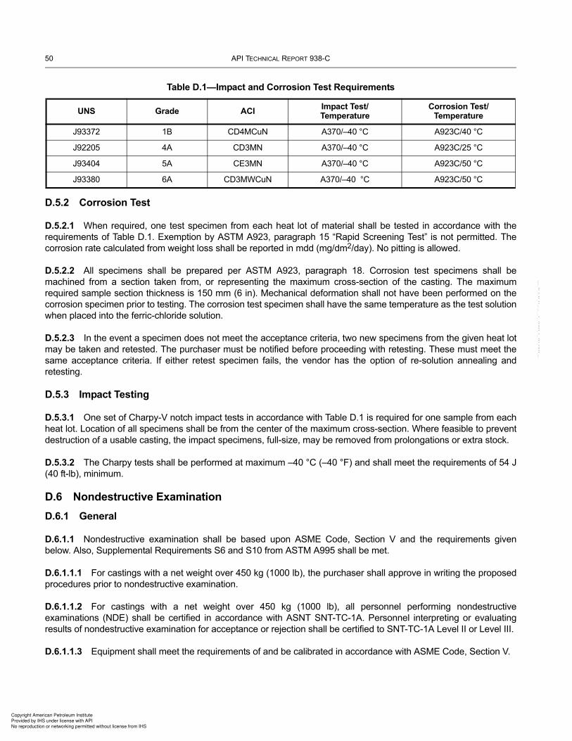
50 API TECHNICAL REPORT 938-C
D.5.2 Corrosion Test
D.5.2.1 When required, one test specimen from each heat lot of material shall be tested in accordance with the
requirements of Table D.1. Exemption by ASTM A923, paragraph 15 “Rapid Screening Test” is not permitted. The
corrosion rate calculated from weight loss shall be reported in mdd (mg/dm2/day). No pitting is allowed.
D.5.2.2 All specimens shall be prepared per ASTM A923, paragraph 18. Corrosion test specimens shall be
machined from a section taken from, or representing the maximum cross-section of the casting. The maximum
required sample section thickness is 150 mm (6 in). Mechanical deformation shall not have been performed on the
corrosion specimen prior to testing. The corrosion test specimen shall have the same temperature as the test solution
when placed into the ferric-chloride solution.
D.5.2.3 In the event a specimen does not meet the acceptance criteria, two new specimens from the given heat lot
may be taken and retested. The purchaser must be notified before proceeding with retesting. These must meet the
same acceptance criteria. If either retest specimen fails, the vendor has the option of re-solution annealing and
retesting.
D.5.3 Impact Testing
D.5.3.1 One set of Charpy-V notch impact tests in accordance with Table D.1 is required for one sample from each
heat lot. Location of all specimens shall be from the center of the maximum cross-section. Where feasible to prevent
destruction of a usable casting, the impact specimens, full-size, may be removed from prolongations or extra stock.
D.5.3.2 The Charpy tests shall be performed at maximum –40 °C (–40 °F) and shall meet the requirements of 54 J
(40 ft-lb), minimum.
D.6 Nondestructive Examination
D.6.1 General
D.6.1.1 Nondestructive examination shall be based upon ASME Code, Section V and the requirements given
below. Also, Supplemental Requirements S6 and S10 from ASTM A995 shall be met.
D.6.1.1.1 For castings with a net weight over 450 kg (1000 lb), the purchaser shall approve in writing the proposed
procedures prior to nondestructive examination.
D.6.1.1.2 For castings with a net weight over 450 kg (1000 lb), all personnel performing nondestructive
examinations (NDE) shall be certified in accordance with ASNT SNT-TC-1A. Personnel interpreting or evaluating
results of nondestructive examination for acceptance or rejection shall be certified to SNT-TC-1A Level II or Level III.
D.6.1.1.3 Equipment shall meet the requirements of and be calibrated in accordance with ASME Code, Section V.
Table D.1—Impact and Corrosion Test Requirements
UNS Grade ACIImpact Test/Temperature
Corrosion Test/Temperature
J93372 1B CD4MCuN A370/–40 °C A923C/40 °C
J92205 4A CD3MN A370/–40 °C A923C/25 °C
J93404 5A CE3MN A370/–40 °C A923C/50 °C
J93380 6A CD3MWCuN A370/–40 °C A923C/50 °C
Copyright American Petroleum Institute
Provided by IHS under license with API
No reproduction or networking permitted without license from IHS
--`,,,,,`,,,``,`,,,,,,``,```-`-`,,`,,`,`,,`---

USE OF DUPLEX STAINLESS STEELS IN THE OIL REFINING INDUSTRY 51
D.6.2 Visual Inspection
All castings shall be visually inspected per MSS SP-55 or ASTM A802. For ASTM A802 acceptance shall be in
accordance with Level II.
D.6.3 Liquid Penetrant Examination
D.6.3.1 Liquid penetrant examination is required for all castings.
D.6.3.2 Procedures for liquid penetrant examination (PT) shall be per ASTM E165.
D.6.3.3 The external surface, accessible wetted surfaces, and repairs require 100 % PT. Acceptance criteria shall
be in accordance with ASTM A903 Level I.
D.6.4 Radiography
D.6.4.1 For all castings for pressure rating Class 1500 and higher, radiography is required of all critical areas and
butt weld ends after the final heat treatment per ASTM A703, Supplementary Requirement S5.
D.6.4.2 Castings for rating Class 600 and 900 require radiography of all butt weld ends and of the critical areas of
the pilot casting of each pattern after the final heat treatment per ASTM A703, Supplementary Requirement S5.
D.6.4.3 The acceptance shall be per MSS SP 54.
D.7 Repairs
D.7.1 Welding processes shall be SMAW or GTAW.
D.7.2 No autogenous welding is allowed.
D.7.3 Welding procedures (WPS and PQR) and welders shall be qualified per ASME Code, Section IX. This
includes impact testing of full-size specimens at –40 °C (–40 °F) to meet minimum weld metal and heat affected zone
impact energy of 34 J (25 ft-lb) and 54 J (40 ft-lb), respectively.
D.7.4 Filler metals for repair welds shall be selected based on Table D.2, below, and matching or overmatching
fillers are allowed. For repairs requiring postweld heat treatment (solution annealing and water quenching), it is
advised to consult with the welding consumables manufacturer for recommended filler metals, especially in critical
services. There are special welding consumables made for castings.
Table D.2—Welding Consumables
Process Grade 4A Grade 1B, 5A and 6A
SMAW SFA 5.4 E2209 SFA 5.4 E2553, E2594 or E2595
GTAW/GMAW SFA 5.9 ER2209 SFA 5.9 ER2553, or ER2594
SAW SFA 5.9 ER2209 with a flux designed for DSSs SFA 5.9 ER2594 with a flux designed for DSSs
FCAW SFA 5.22 E2209TX-X or EC2209SFA 5.22 E2553TX-X, E2594TX-X,
EC2553, or EC2594
NOTE This table does not cover some of the specialized 25 % Cr alloys and the material manufacturer’s (i.e. the alloy supplier’s) recommendations on welding consumables should be followed.
Copyright American Petroleum Institute
Provided by IHS under license with API
No reproduction or networking permitted without license from IHS
--`,,,,,`,,,``,`,,,,,,``,```-`-`,,`,,`,`,,`---

52 API TECHNICAL REPORT 938-C
D.7.5 Castings require post weld heat treatment (solution annealing) per D.2.2 after all major repair welding of
Grade 1B, 4A, 5A, and 6A. PWHT (solution annealing) is also required for minor repair welding of wetted surfaces of
Grade 1B, 5A, and 6A.
D.8 Certification
D.8.1 The vendor shall certify in writing that the castings meet the requirements of the latest edition of ASTM
A 995 (including applicable supplementary requirements of ASTM A703) and this specification.
D.8.2 Certified copies of the material certifications meeting the requirements of ASTM and showing the results of all
tests shall be furnished to the purchaser.
D.8.3 All certifications shall be signed by a responsible officer of the vendor, whose identity shall be legally
displayed.
Copyright American Petroleum Institute
Provided by IHS under license with API
No reproduction or networking permitted without license from IHS
--`,,,,,`,,,``,`,,,,,,``,```-`-`,,`,,`,`,,`---

53
Annex E(informative)
Example of a Hot Isostatically-pressed (HIP) Duplex SS Material Specification
E.1 General
E.1.1 Scope
This specification is informative and is to be used as a manufacturing guide for HIP’ed DSSs materials. The materials
are covered by ASTM A988, and manufacturing practices and testing of material are included.
E.1.2 Definitions
Capsule – Container used for encapsulation and hot isostatic pressing of the powder.
Cross Contamination – An intermix of powder of different alloy type.
Filling tube – A tube on top of the capsule through which powder is filled.
HIP – Hot Isostatic Pressing.
Gas atomization – The process in which a melt is slushed into small particles in a controlled chamber. When the
particles solidify, a metal powder where each particle has the same composition as the melt is formed.
QTC – Quality Test Coupon.
E.1.3 Referenced Documents
The following standards and specifications shall be considered as a part of this specification. All documents shall be the latest editions published.
ASTM A370, Standard Test Methods and Definitions for Mechanical Testing of Steel Products
ASTM A388, Standard Practice for Ultrasonic Examination of Steel Forgings
ASTM A923, Standard Test Methods for Detecting Detrimental Intermetallic Phase in Duplex Austenitic/Ferritic
Stainless Steels
ASTM A988, Standard Specification for Hot Isostatically-Pressed Stainless Steel Flanges, Fittings, Valves, and Parts
for High Temperature Service
ASTM E165, Standard Practice for Liquid Penetrant Examination for General Industry
ASTM E562, Standard Practice for Determining Volume Fraction by Systematic Manual Point Count
ASTM G48, Standard Test Methods for Pitting and Crevice Corrosion Resistance of Stainless Steels and Related
Alloys by Use of Ferric Chloride Solution
DIN 50602, Metallographic examination; microscopic examination of special steels using standard diagrams to
assess the content of non-metallic inclusions
EN 10204, European Standard, Metallic Products, Type of Inspection Documents
Copyright American Petroleum Institute
Provided by IHS under license with API
No reproduction or networking permitted without license from IHS
--`,,,,,`,,,``,`,,,,,,``,```-`-`,,`,,`,`,,`---

54 API TECHNICAL REPORT 938-C
E.2 Material and Manufacture
E.2.1 Manufacturing Practice
E.2.1.1 The HIP’ed parts shall be manufactured from pre-alloyed powder. The powder shall be manufactured using
a gas atomization process, where the melting process in use can produce a specific composition.
E.2.1.2 If powder blends from different heats are used, all blends shall fulfill the standard requirements. Powder
blends shall also be mixed in such manner that a homogeneous blend is obtained, both in composition and particle
size.
E.2.1.3 The powder shall be stored in such manner that it is not in contact with the direct environment and to avoid
humidity and oxidation.
E.2.1.4 The HIP’ed part shall be manufactured from a homogeneous powder blend by filling a capsule with powder,
evacuating the capsule and then sealing it thoroughly.
E.2.1.5 The material used to produce capsules shall not have a harmful effect on the DSSs material, e.g. low alloy
carbon steel can be used. The capsules shall be cleaned of any type of dust or residue from the welding procedure.
E.2.1.6 The HIP’ing operation shall use adequate temperature, pressure and time to achieve full densification of the
whole part to a solid compact.
E.2.1.7 The capsule plate can be removed by pickling or machining.
E.2.2 Chemical Composition
Both powder blend and the HIP’ed part shall have a chemical composition that conforms to the specified composition
in ASTM A988.
E.2.3 Heat Treatment
E.2.3.1 Solution annealing followed by water quenching shall be performed. Components shall be placed so that
free circulation around each component can be ensured during the heat treatment process, including quenching.
E.2.3.2 The heat treatment can be performed prior to, or after, removal of the capsule plate. If the capsule plate is
removed prior to heat treatment, the process has to be performed in a protective environment.
E.3 Testing of Material Properties
E.3.1 Test Material
E.3.1.1 Material properties can be tested on elongations (such as fill stems) of HIP’ed component or on a QTC of
adequate size that has been produced from the same powder heat and heat treated in the same batch as the HIP’ed
component. A minimum of one test sample is required from each production batch, which is each powder batch and
quench lot.
E.3.1.2 All test qualification shall be performed on a similar position in the test sample. T /4 (thickness/4) shall be
used for parts >50 mm and T /2 for parts <50 mm, unless otherwise specified by buyer.
E.3.1.3 Densification shall be tested using argon analysis and on every single HIP’ed component at an adequate
position.
Copyright American Petroleum Institute
Provided by IHS under license with API
No reproduction or networking permitted without license from IHS
--`,,,,,`,,,``,`,,,,,,``,```-`-`,,`,,`,`,,`---

USE OF DUPLEX STAINLESS STEELS IN THE OIL REFINING INDUSTRY 55
E.3.2 Microstructure
E.3.2.1 The microstructure shall be investigated according to ASTM A923 Method A to determine the presence of
deleterious precipitations. One specimen etched in 40 % sodium hydroxide solution shall be used for examination.
The examination shall be performed using 400X to 500X magnification and the polish shall be performed to adequate
finish.
E.3.2.2 Ferrite content shall be determined with the point count method according to ASTM E562. A similar
specimen as in E.3.2.1 shall be used for examination. The ferrite content shall be within 40 % to 60 %.
E.3.2.3 Control of cross contamination shall be performed on etched material according to DIN 50602, Method K.
The etching shall be performed with adequate procedure to discover possible cross contamination. Preferably,
etching that is suitable for the duplex alloy shall be used. Cross contamination shall meet K3 < 10.
E.3.2.4 Control of non-metallic inclusions shall be performed on polished material according to DIN 50602, Method
K. Polishing shall be of adequate finish for examination. Inclusion levels shall meet K3 < 10.
E.3.3 Mechanical Properties
E.3.3.1 Tensile testing shall be performed according to ASTM A370 and meet the requirements of ASTM A988 for
the specific alloy.
E.3.3.2 Impact toughness shall be tested with Charpy-V notch testing according to ASTM A370 on one set
(including 3 specimens) of each test sample. The test temperature shall be –46 °C (–51 °F) and the impact toughness
shall be minimum 45J in average and minimum 35J on a single sample.
E.3.4 Corrosion Testing
E.3.4.1 Corrosion testing shall be performed according to ASTM G48 Method A.
E.3.4.2 Materials of 25Cr shall be tested at a temperature of 50 °C (122 °F) and exposure time 24h. After the test
exposure, the specimen shall be pickled for 5 minutes at 60 °C (140 °F) in a solution of 20 % HNO3 + 5 % HF. No
pitting shall be observed in 20X magnification and weight loss shall be less than 4.0 g/m2.
E.3.4.3 Materials of 22Cr shall be tested at a temperature of 25 °C (77 °F) and exposure time 24h. After the test
exposure, the specimen shall be pickled for 5 minutes at 60 °C (140 °F) in a solution of 20 % HNO3 + 5 % HF. No
pitting shall be observed in 20X magnification and weight loss shall be less than 4.0 g/m2 (0.0040 oz/ft2).
E.3.5 Densification
Argon level shall be tested using gas chromatography, argon content shall be ≤ 0.05 ppm on materials atomized in
nitrogen gas.
E.4 Non-Destructive Testing
E.4.1 Ultrasonic Testing
E.4.1.1 Ultrasonic testing is to be performed on the heat treated and pickled part. The testing shall be performed
according to ASTM A388.
E.4.1.2 The component shall have a surface condition that is suitable for ultrasonic testing. Manual grinding may be
required to ensure suitable conditions.
Copyright American Petroleum Institute
Provided by IHS under license with API
No reproduction or networking permitted without license from IHS
--`,,,,,`,,,``,`,,,,,,``,```-`-`,,`,,`,`,,`---
56 API TECHNICAL REPORT 938-C
E.4.2 Liquid Penetrant Testing
If liquid penetrant testing is to be performed, it shall be performed on the heat treated, pickled and machined part. The
testing shall be performed according to ASTM E165.
E.5 Finish and Appearance
The surface shall be ground to remove damaging edges and corners. The surface of all items shall be pickled.
E.6 Handling and Packing
Handling and packing must be done with care so that no contamination of other metallic materials is introduced to the
component surface. All handling equipment in direct contact must be clean.
E.7 Certification
A certificate shall be written and submitted to the purchaser according to EN 10204 3.1 or 3.2, ASTM or other
applicable material specification.
Copyright American Petroleum Institute
Provided by IHS under license with API
No reproduction or networking permitted without license from IHS
--`,,,,,`,,,``,`,,,,,,``,```-`-`,,`,,`,`,,`---

57
Bibliography
[1] Robert F. Herbert III, “Can Duplex Stainless Steels Improve the Key Performance Indicators of an Operating
Unit,” Duplex America 2000 Conference, Houston, Texas, Paper DA2 101, March 2000.
[2] Robert N. Gunn, Duplex Stainless Steels, Microstructure, Properties and Applications, Abington Publishing,
Cambridge England, 1997.
[3] Ralph M. Davison and James D. Redmond, “Practical Guide to Using Duplex Stainless Steels,” Materials
Performance, Jan. 1990, pp 57–62.
[4] J. Charles and P. Chemelle, “The history of duplex developments, nowadays DSS properties and duplex
market future trends,” Duplex Stainless Steel Conference, Beaune, France, Oct. 2010.
[5] Sudhakar P.V. Mahajanam, Raymundo P. Case, Hernan E. Rincon, Mike W. Joosten, Stig Gjesdal, and
Henning Monsen, “Effect of Sigma Phase on the Corrosion and Stress Corrosion of 2205 and 2507 Duplex
Stainless Steels,” NACE Corrosion/2011, Paper No. 11173, April 2011.
[6] Roger Francis and Stan Hebdon, “The Limiting Section Thickness for Duplex Stainless Steels,” NACE
Corrosion/2014, Paper C2014-3651, March 2014.
[7] Amelie Fanica, “Duplex Stainless Steel Welding,” Dubai, February 2008.
[8] Sandvik Materials Technology Brochure, S-120-ENG, “Sandvik Duplex Stainless Steels” January 2009.
[9] K. Toba, M. Ueyama, K. Kawano and J. Sakai, “Corrosion of Carbon Steel and Alloys in Concentrated
Ammonium Chloride Solutions,” Corrosion, Vol. 68, No. 11, Nov. 2012, p. 1049–1056.
[10] K. Toba, T. Suzuki, K. Kawano and J. Sakai, “Effect of Relative Humidity on Ammonium Chloride Corrosion in
Refineries,” Corrosion, Vol. 67, No. 5, May 2011, p. 05505-1 to 05505-7
[11] Sandvik Materials Technology Brochure, S- 51-63-ENG, “Sandvik SAF 2707 HD® (UNS S32707)—a hyper-
duplex stainless steel for severe chloride containing environments”, November 2006.
[12] Josefin Eidhagen, Ulf Kivisakk and Abby Sanchez, “Case stories in refinery and localized corrosion testing of
UNS S32707 in chlorides,” NACE Corrosion/2014, Paper C2014-4053, March 2014.
[13] OutoKumpu Brochure, 1088EN/1008EN-GB, “Duplex Stainless Steel,” Feb. 2009.
[14] T. Prosek, A. Iversen and C. Taxen, “Low Temperature Stress Corrosion Cracking of Stainless Steels in the
Atmosphere in Presence of Chloride Deposits,” NACE Corrosion/2008, Paper 08484, March 2008.
[15] R.F.A. Pettersson and E. Johansson, “Stress Corrosion Cracking Resistance of Duplex Grades,” Duplex
World 2010, The Netherlands: KCI Publishing, 2010.
[16] Tomas Prosek, Anne Le Gac, Sandra Le Manchet, Elisabeth Johansson, Christian Lojewski, Amelie Fanica,
Carolina Canderyd, Francois Dupoiron, Tom Snauwaert, Fleur Maas, Benny Droesbeke, and Dominique
Thierry, “Application Limits of Austenitic and Duplex Stainless Steels in Presence of Chloride Deposits in
Atmospheric Conditions,” Stainless Steel World Conference 2013, Maastricht, the Netherlands, October,
2013.
Copyright American Petroleum Institute
Provided by IHS under license with API
No reproduction or networking permitted without license from IHS
--`,,,,,`,,,``,`,,,,,,``,```-`-`,,`,,`,`,,`---

58 API TECHNICAL REPORT 938-C
[17] Sandra Le Manchet, Christian Lojewski and Amelie Fanica, “Resistance to Stress Corrosion Cracking of
Duplex Stainless Steels,” NACE Corrosion/2013, Paper C2013-2086, March 2013.
[18] Karly Moore and Cathleen Shargay, “Duplex Stainless Steel Chloride Stress Corrosion Cracking Risk in the
Oil Refining Industry,” NACE Corrosion/2013, Paper C2013-2520, March 2013.
[19] A. Turnbull and G. Hinds, “Stress Corrosion Cracking of Duplex Stainless Steel Under Simulated Evaporation
Conditions,” NACE Corrosion/07, Paper 07474, March 2007.
[20] Thierry Cassagne, Jerome Peultier, Sandra Le Manchet and Claude Duret, “An Update on the Use of Duplex
Stainless Steels in Sour Environments,” NACE Corrosion/2012, Paper C2012-0001381, March 2012.
[21] Sandra Le Manchet, Christian Lojewski, Amelie Fanica and Thierry Cassagne, “Corrosion Resistance of UNS
S31803 Duplex Stainless Steel in Sour Environments,” NACE Corrosion/2014, Paper C2014-3727, March
2014.
[22] Phil Anderson, “Sulfide Stress Cracking (SSC) of Duplex 2205 Welds in REAC Services—Correlations with
Process Conditions,” API 938-C Meeting, Sep. 2012.
[23] Richard Horvath, Michael Cayard and Russell Kane, “Prediction and Assessment of Ammonium Bisulfide
Corrosion Under Refinery Sour Water Service Conditions,” NACE Corrosion/2006, Paper 06576, Houston,
Texas, March 2006.
[24] Richard Horvath, Vishal Lagad, Sridhar Srinivasan and Russell Kane, Prediction and Assessment of
Ammonium Bisulfide Corrosion Under Refinery Sour Water Service Conditions—Part 2,” NACE Corrosion/
2010, Paper 10349, March 2010.
[25] A.K. Singh, E.L. Bereczky and A.J. Bagdasarian, “Duplex Stainless Steel in Refinery Hydroprocessing Units
Success and Failure Stories,” TWI Duplex Stainless Steels 94, Paper 16, Glasgow, Scotland, November 13–
16, 1994.
[26] Cathleen Shargay, James Turner, Barry Messer, Deyuan Fan and William Fort, “Design Considerations to
Minimize Chloride Corrosion in Hydrotreater REACs,” NACE Corrosion/2001, Paper 01543, March 2001.
[27] Julio G. Maldonado and Russell D. Kane, “Failure Analysis Investigation of Super Duplex Stainless Steel
Tubing,” Stainless Steel World Conference, Paper P0240, Houston, Texas, February 12–14, 2002.
[28] International Institute of Welding, Doc. II-1190-92, Welding Duplex and Super-duplex Stainless Steels—A
Guide for Industry, L. van Nassau, H. Meelker and J. Hilkes, July 1992.
[29] Sabrina Ronneteg, “Development in the use of DSS/SDSS in refinery heat exchanger applications,” NACE
Corrosion Technology Week, 2008.
[30] Sandvik Materials Technology Brochure, S-51-53-ENG, “The Sandvik Duplex Family of Stainless Steels.
Summary of Data,” December 1994.
[31] R. Pettersson, C. Canderyd, J.Y. Jonsson, P-E. Arnvig, “Qualification Testing of Lean Duplex Stainless Steels
for the Process Industry,” NACE Corrosion/2012, Paper C2012-0001527, March 2012.
[32] Sophia Ekman, Mikael Johansson, Jan Johansson and Elisabeth Johansson, “Inhibited Ferric Chloride
Corrosion Test of Lean Duplex Stainless Steel Welds,” NACE Corrosion/2014, Paper C2014-4076, March
2014.
Copyright American Petroleum Institute
Provided by IHS under license with API
No reproduction or networking permitted without license from IHS
--`,,,,,`,,,``,`,,,,,,``,```-`-`,,`,,`,`,,`---

USE OF DUPLEX STAINLESS STEELS IN THE OIL REFINING INDUSTRY 59
[33] Marcelo Senatore and Jonas Howling, “Application of Twisted Hyper Stainless Steel Duplex on Crude Unit
Overhead Condenser,” NACE Corrosion/2010, Paper 10357, March 2010.
[34] Anders Eklund, Björn-Olof Bengtsson, James F. Scanlon, and Greg Del Corso, “Properties of P/M Hipped
Stainless Steel,” Stainless Steel World Conference, Paper PSA10_012, 2010.
[35] Mats Peterssen, “HIP Presentation,” API 938-C Meeting Minutes, April 2012.
[36] Jonas Howing, “Austenite spacing—What does it tell us?”, API 938-C Meeting Minutes, April 2012.
[37] Cathleen Shargay, Karly Moore and John W. Wodarcyk, “Heat Treatment Issues on Stainless Steel Heat
Exchanger Tubes,” NACE Corrosion/2009, Paper 09338, March 2009.
[38] Cathleen Shargay, Tina Tajalli and Richard Clarke, “Optimizing Tube-to-Tubesheet Joints for Duplex Stainless
Steel Air Coolers and Exchangers,” Stainless Steel World Conference, Paper PSA10_002, 2010.
[39] International Molybdenum Association, “Practical Guidelines for the Fabrication of Duplex Stainless Steel,”
ISBN 978-1-907470-00-4, 2009.
[40] J. Charles, “Super Duplex Stainless Steels: Structure and Properties,” Duplex Stainless Steel Conference in
Beaune, France, 1991 (p 3–48; vol. 1).
Copyright American Petroleum Institute
Provided by IHS under license with API
No reproduction or networking permitted without license from IHS
--`,,,,,`,,,``,`,,,,,,``,```-`-`,,`,,`,`,,`---

Copyright American Petroleum Institute
Provided by IHS under license with API
No reproduction or networking permitted without license from IHS
--`,,,,,`,,,``,`,,,,,,``,```-`-`,,`,,`,`,,`---

Copyright American Petroleum Institute
Provided by IHS under license with API Licensee=Suncor Energy Inc - Sites 1, 3, & 7/9992021001, User=Abdolmaleki, Alire
Not for Resale, 03/03/2016 09:51:40 MSTNo reproduction or networking permitted without license from IHS
--`,,,,,`,,,``,`,,,,,,``,```-`-`,,`,,`,`,,`---

Product No. C938C03
Copyright American Petroleum Institute
Provided by IHS under license with API Licensee=Suncor Energy Inc - Sites 1, 3, & 7/9992021001, User=Abdolmaleki, Alire
Not for Resale, 03/03/2016 09:51:40 MSTNo reproduction or networking permitted without license from IHS
--`,,,,,`,,,``,`,,,,,,``,```-`-`,,`,,`,`,,`---


![An Introduction to Duplex Stainless Steels[1]](https://img.pdfslide.net/doc/110x75/5476ed11b4af9fc80a8b654f/an-introduction-to-duplex-stainless-steels1.jpg)