Embed Size (px)
Citation preview
62 TRANSPORTATION RESEARCH RECORD 1198
Use of Guardrails on Low Fill Bridge Length Culverts
T. J. HIRSCH AND DALE BEGGS
When multiple box culverts span more than 20 feet, the American Association of State Highway Transportation Officials (AASHTO) defines them as bridge length and, thus, normally require the use of a full-strength, rigid bridgerail. Using a rigid bridgerail creates a transition problem between the flexible metal beam guard fence, which is commonly used upstream of the bridgerail. It would be safer and more economical to continue the flexible metal beam guard fence across the culvert even when the culvert is more than 20 feet long and when the soil fill depth over the culvert is less than the standard guardrail post embedment depth (38 inches in Texas). It was believed that more post could be used (reduced post spacing) with a shallow embedment to achieve the desired guardrail strength. A metal beam guard fence design of this type was crash tested in this study and proved to be unsatisfactory. Another concept investigated was to rigidly mount steel guard fence posts to the top of the culvert deck when full soil embedment could not be achieved. A design of this type was also crash tested in this study and proved to be satisfactory.
When multiple box culverts span more than 20 feet, the American Association of State Highway Transportation Officials (AASHTO) (1) defines them as bridge length and, thus, normally require the use of a full-strength, rigid bridgerail. Using a rigid bridgerail creates a transition problem between the flexible metal beam guard fence, which is commonly used upstream of the bridgerail. It would be safer and more economical to continue the flexible metal beam guard fence across the culvert even when the culvert is more than 20 feet long and when the soil fill depth over the culvert is less than the standard guardrail post embedment depth of 38 inches. Many of these culverts have soil fills 6 to 38 inches deep.
The objective of this research study was to develop information to promote the concept of continuing the approach flexible metal beam guard fence across bridge length (over 20 feet) multiple box culverts. This concept is believed to be safer, more economical, and more effective than using rigid bridgerails on such culverts.
Research Report 405-1, The Effects of Embedment Depth, Soil Properties, and Post Type on the Performance of Highway Guardrail Posts (2) presented data which could be used to modify the current metal beam guard fence for application when the full 38-inch post embedment depth could not be achieved. It was believed that more posts could be used with a shallow embedment to achieve the desired guardrail strength. A metal beam guard fence design of this type was crash tested in this study and proved to be unsatisfactory.
Civil Engineering Department, Texas Transportation Institute, The Texas A&M University System, College Station, Tex. 77843.
Another concept investigated was to rigidly mount the guard fence post to the top of the culvert deck when full soil embedment could not be achieved. A design of this type was also crash tested in this study and proved to be satisfactory.
METAL BEAM GUARD FENCE DESIGNS AND CRASH TESTS
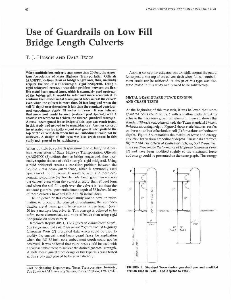
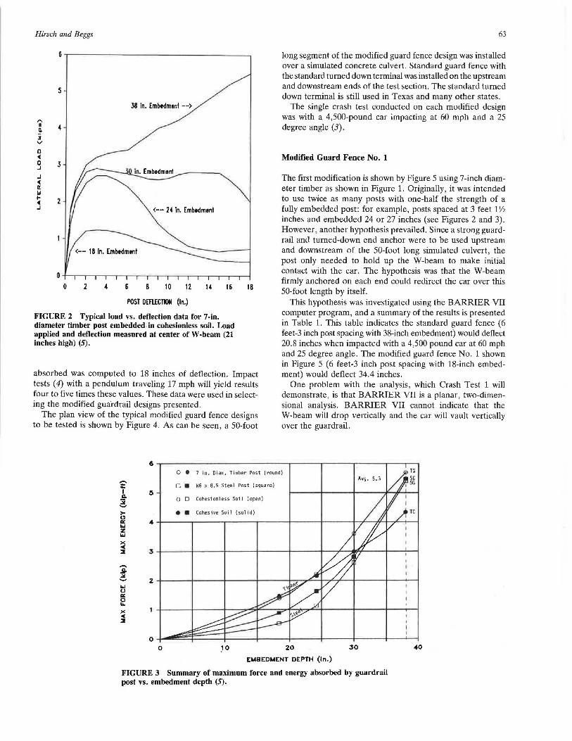
At the beginning of this research, it was believed that more guardrail posts could be used with a shallow embedment to achieve the necessary guard rail strength. Figure 1 shows the standard 38-inch embedment with the Texas standard 27-inch W-beam mounting height. Figure 2 shows static load test results on these posts in a cohesionless soil (3) for various embedment depths. Figure 3 summarizes the maximum force and energy absorbed for various embedment depths. These data are from figure 2 and The Effects of Embedment Depth, Soil Properties, and Post Type on the Performance of Highway Guardrail Posts (2) and have been modified slightly so the maximum force and energy could be presented on the same graph. The energy
4"
.., 27 "
0 21 •
a. ~
" ~ 21 " E 21 · ;::
:"ri ~ 0
"' .. h
" ~
)" 1"
di am. diam.
~ 13" 27"
Test l Test 2
~ .., "' i x .., " a.
LJ >-- ~
.., c
j .n
FIGURE 1 Standard Texas timber guardrail post and modified version used in Tests 1 and 2 (prior to 1984).
Hirsch and Beggs
5
38 in. Embedmenl -->
"' I 4 a. i v
0 <( 0 3 .J
.J <( a: Id I- 2 <( .J <-- 24 In. Embedmenl
<-- 18 in. Embedmenl
POST DEFLECTION (in.)
FIGURE 2 Typical load vs. deflection data for 7-in. diameter timber post embedded-in cohesionless soil. Load applied and deflection measured at center of W-beam (21 inches high) (5).
absorbed was computed to 18 inches of deflection. Impact tests ( 4) with a pendulum traveling 17 mph will yield results four to five times these values. These data were used in selecting the modified guardrail designs presented.
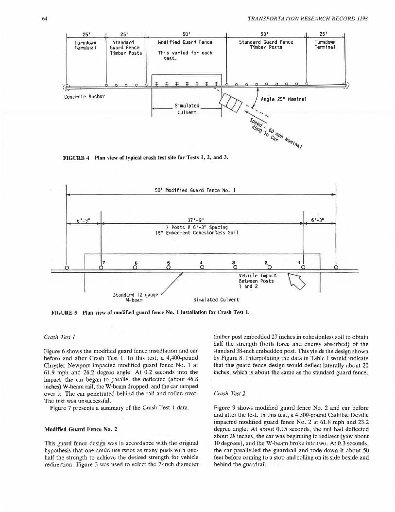
The plan view of the typical modified guard fence designs to be tested is shown by Figure 4. As can be seen, a 50-foot
63
long segment of the modified guard fence design was installed over a simulated concrete culvert. Standard guard fence with the standard turned down terminal was installed on the upstream and downstream ends of the test section. The standard turned down terminal is still used in Texas and many other states.
The single crash test conducted on each modified design was with a 4,500-pound car impacting at 60 mph and a 25 degree angle (3).
Modified Guard Fence No. 1
The first modification is shown by Figure 5 using 7-inch diameter timber as shown in Figure 1. Originally, it was intended to use twice as many posts with one-half the strength of a fully embedded post: for example, posts spaced at 3 feet 1 Yz inches and embedded 24 or 27 inches (see Figures 2 and 3). However, another hypothesis prevailed. Since a strong guardrail and turned-down end anchor were to be used upstream and downstream of the 50-foot long simulated culvert, the post only needed to hold up the W-beam to make initial contact with the car. The hypothesis was that the W-beam firmly anchored on each end could redirect the car over this 50-foot length by itself.
This hypothesis was investigated using the BARRIER VII computer program, and a summary of the results is presented in Table 1. This table indicates the standard guard fence ( 6 feet-3 inch post spacing with 38-inch embedment) would deflect 20.8 inches when impacted with a 4,500 pound car at 60 mph and 25 degree angle. The modified guard fence No. 1 shown in Figure 5 (6 feet-3 inch post spacing with 18-inch embedment) would deflect 34.4 inches.
One problem with the analysis, which Crash Test 1 will demonstrate, is that BARRIER VII is a planar, two-dimensional analysis. BARRIER VII cannot indicate that the W-beam will drop vertically and the car will vault vertically over the guardrail.
0 • 7 in. Diam. Timber Post (round) ,.... = I a.. :i ...... >-Cl II:: ..... z ..... x <( :I 3
,.... .9-:1' ...... 2 ..... u II:: 0 LA.
x <( :I
0 0
O • W6 x 8.5 Steel Post (square)
o O Cohesionless Soil (open)
e • Cohesive Soil (solid)
20
EMBEDMENT DEPTH (In.)
Avg. 5.3
30
FIGURE 3 Summary of maximum force and energy absorbed by guardrail post vs. embedment depth (5).
40
64
25' Turndown Tenninal
Concrete Anchor
25' Stan~ard
C:.uard Fence Timber Posts
50' ~odified Guar~ Fence
This varied for each test.
TRANSPORTATION RESEARCH RECORD 1198
50' 5tandard Guard Fence
Timber Posts
Angle 25° Nominal
25' Turndown Tenninal
--- Simulateci _ _ _ Culvert
FIGURE 4 Plan view of typical crash test site for Tests 1, 2, and 3.
50' Modified Guard Fence No. l -
6'-3" 37' -6" 6'-3'' 7 Posts @ 6'-3" Spacing
18" Embedment Cohesionless Soil
I 7 0 ()
6 6 0
,,,, •• ,. 12 ''"'' ~ W-beam
4 3 0 0
Simulated Culvert
2.0
Veh1 cl e Impact Between Posts l and 2
t I 0 0
~ I FIGURE 5 Plan view of modified guard fence No. 1 installation for Crash Test 1.
Crash Test 1
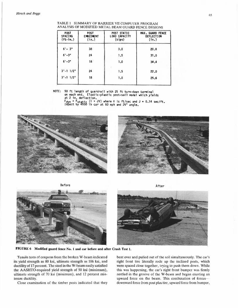
Figure 6 shows the modified guard fence installation and car before and after Crash Test 1. In this test, a 4,400-pound Chrysler Newport impacted modified guard fence No. 1 at 61.9 mph and 26.2 degree angle. At 0.2 seconds into the impact, the car began to parallel the deflected (about 46.8 inches) W-beam rail, the W-beam dropped, and the car ramped over it. The car penetrated behind the rail and rolled over. The test was unsuccessful.
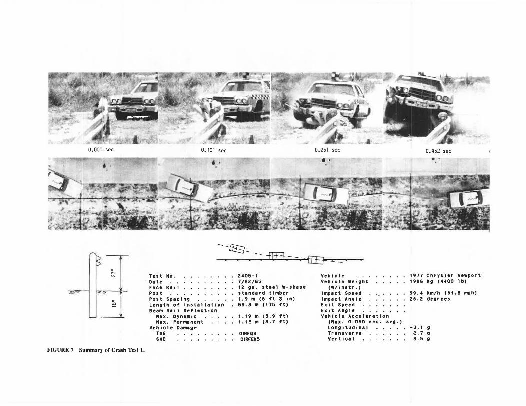
Figure 7 presents a summary of the Crash Test 1 data.
Modified Guard Fence No. 2
This guard fence design was in accordance with the original hypothesis that one could use twice as many posts with onehalf the strength to achieve the desired strength for vehicle redirection. Figure 3 was used to select the 7-inch diameter
timber post embedded 27 inches in cohesionless soil to obtain half the strength (both force and energy absorbed) of the standard 38-inch embedded post. This yields the design shown by Figure 8. Interpolating the data in Table 1 would indicate that this guard fence design would deflect laterally about 20 inches, which is about the same as the standard guard fence.
Crash Test 2
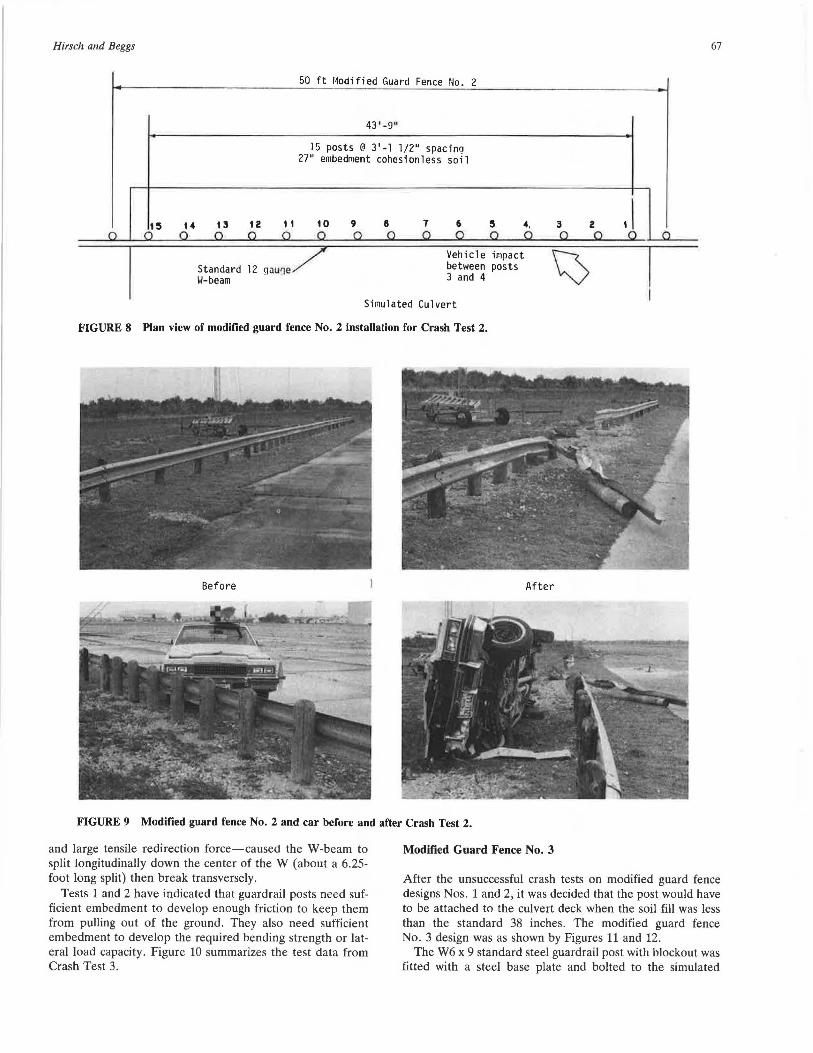
Figure 9 shows modified guard fence No. 2 and car before and after the test. In this test, a 4,500-pound Cadillac Deville impacted modified guard fence No. 2 at 61.8 mph and 23.2 degree angle. At about 0.15 seconds, the rail had deflected about 28 inches, the car was beginning to redirect (yaw about 10 degrees), and the W-beam broke into two. At 0.3 seconds, the car parallelled the guardrail and rode down it about 50 feet before coming to a stop and rolling on its side beside and behind the guardrail.
Hirsch and Beggs
TABLE 1 SUMMARY OF BARRIER VII COMPUTER PROGRAM ANALYSIS OF MODIFIED METAL BEAM GUARD FENCE DESIGNS
POST POST POST STATIC MAX. GUARD FENCE SPACING EMBEDMENT LOAD CAPACITY DEFLECTION (ft-fn.) (fn.) (kfps) (fn.)
6'- 3" 38 3.0 20.8
6'-3" 24 1.5 31.0
6'-3" 18 1.0 34.4
3'-1 1/2" 24 1.5 22.0
3'-1 1/2" 18 1.0 25.6
NOTE : 50 ft length of guardrail with 25 ft turn-down terminal on each end. Elastic-plastic post-soil model which yields at 2 in. deflection. Fdyn = Fstoti8 (1 +JV) where V is ft/sec and J = 0.14 sec/ft. Impact by 450 lb car at 60 mph and 25° angle.
Before After
FIGURE 6 Modified guard fence No. 1 and car before and after Crash Test 1.
65
Tensile tests of coupons from the broken W-beam indicated its yield strength as 80 k i ultimate strength as 106 ksi and ductil ity of 17 percen t. The steel in the W-beam easily satisfied the AASHTO-required yield strength of SO ksi (min imum), ultimate strength of 70 ksi (minimum), and 12 percent minimum ductility.
Close examination of the timber posts indicated that they
bent over and pulled out of the soil simultaneously. The car's right front tire literally rode up the inclined posts, which were spaced close togelher, trying to push them down. While this was happening, the car's right front bumper was firmly nestled in the groove of the W-beam and began exerting an upward force on the beam. This combination of forcesdownward force from post plus tire, upward force from bumper,
0.000 sec
• i·
~ .~
FIGURE 7 Summar) of Crash Test 1.
O. 101 sec 0,251 sec . ' • •
---rn--.
Test No. Date Face Rail Post Post Spacing Length of Installation Beam Rail Deflection
"ax. Dynamic "ax. Permanent
Vehicle Damage TAE SAE
~-----Fff3.- - .-~. . . . . . . 2405-1 7/22/85 12 ga. steel W-shape standard timber 1.9 m (6 ft 3 in) 53.3 m (175 ft)
t.19 m (3.9 ft) t.12 m (3.7 ft)
OtRFQ4 01RFEK5
Vehicle Vehicle Weight
(w/instr.) Impact Speed Impact Angle Exit Speed Exit Ansile Vehicle Acceleration
<"ax. 0.050 sec. avg.) Longitudinal Trans,•erse Vert i c:a l
0.452 sec .. .
1977 Chrysler Newport 1996 kg (4400 lb)
99.4 km/h (61.8 mph) 26.2 degrees
-3.1 g 2.7 g 3.5 g
Hirsch and Beggs 67
50 ft Modified Guard Fence No. 2
43' -9"
15 posts @ 3'-1 1/2" spacinQ 27" embedment cohesionless soil
t3
Standard W-beam
12 to 9 8 7 6 5 '· 3 2
Simulated Culvert
FIGURE 8 Plan view of modified guard fence No. 2 installation for Crash Test 2.
Before After
FIGURE 9 Modified guard fence No. 2 and car before and after Crash Test 2.
and large tensile redirection force-caused the W-beam to split longitudinally down the center of the W (about a 6.25-foot long split) then break transversely.
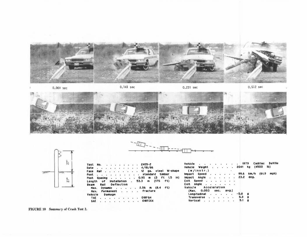
Tests 1 and 2 have indicated that guardrail posts need sufficient embedment to develop enough friction to keep them from pulling out of the ground. They also need sufficient embedment to develop the required bending strength or lateral load capacity. Figure 10 summarizes the test data from Crash Test 3.
Modified Guard Fence No. 3
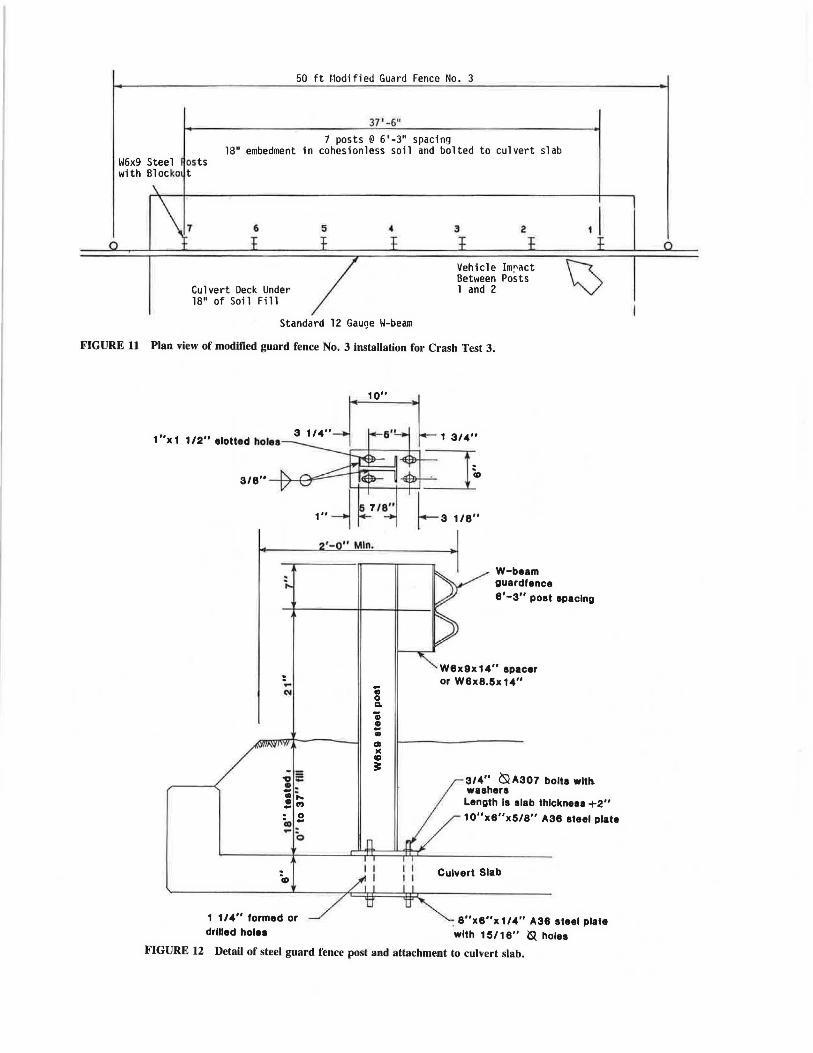
After the unsuccessful crash tests on modified guard fence designs Nos. 1 and 2, it was decided that the post would have to be attached to the culvert deck when the soil fill was less than the standard 38 inches. The modified guard fence No. 3 design was as shown by Figures 11 and 12.
The W6 x 9 standard steel guardrail post with blockout was fitted with a steel base plate and bolted to the simulated
0.000 sec 0.141 sec 0. 231 sec
(~--i - -1JJ:J- - : -fill - -:- -rrn1=-;- r.------..----....-. .
~;.-·
rN
" r-N
Test NO. Date race Rail Poat Poat Spacing Length of lnatallation Beam Rail Deflection
"ax. Dynalltic "ax. Permanent
Vehicle Damage TAE SAE
FIGURE 10 Summary of Crash Test 2.
2405-2 4/t8/86 t2 ga. steel w-shape standard timber
o.95 m (3 ft t.5 in) 53.3 m (t75 ft)
2.56 m (8.4 ft) fracture
OtRFQ4 01RFEK4
Vehicle Vehicle Weight
(•/instr.) Impact Speed Impact Angle Exit Speed Exit Angle Vehicle Acceleration
<"ax. 0.050 sec. avg.) Longitudinal Transverse Vertical
0.512 sec
1979 2041 kg
Cadillac (4500
99.6 km/h (61.9 23.2 deg.
-5.8 g 5.3 g 5.1 g
De Ville lb)
mph)
50 ft f.lodified Guard Fence No. 3
37'-6"
7 posts @ 6'-3" spacing 18" embedment in cohcsionless soil and bolted to culvert slab
1~6x9 Steel os ts with Bloc ko t
1 6 5
Culvert Deck Under 18" of Soil Fi 11
Standard
4
12 Gauge W-beam
3 2 , I Vehicle Im~act
~ Bet1~een Posts l and 2
FIGURE 11 Plan view of modified guard fence No. 3 installation for Crash Test 3.
1"x1 112" 1lotted hole1
. ... ~
,;e !: ..... .! C'J
- 0 io .. ... : 0
1 1/4" formed or drllled holes
'- "Min.
• 0 a. 'i • .. • OI )(
CD 3:
W-beam guardfence 8'-3" poet spacing
W8x9x14" spacer or W8x8.6x14"
314" ~ A307 bolts with. washers Length la slab thlckneaa +2"
10"x8"xS/8" A38 eteel plate
Culvert Slab
. 8"x8"x114" A36 steel plate with 15/ 18" iQ holes
FIGURE 12 Detail of steel guard fence post and attachment to culvert slab.
70 TRANSPORTATION RESEARCH RECORD 1198
39
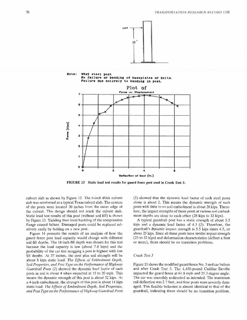
Hote: WGz9 steel post Ro failure or bending of baseplates or bolts. Failure due entirely to bendin1 in post.
Plot of 7
,.Dram vs. Db1plaa•m•nf
II ~ ~ I/ ...
I I r I
I .. 3
2
I 0
0 2 II
D•fl•atlan at laad (In.)
FIGURE 13 Static load test results for guard fence post used in Crash Test 3.
culvert slab as shown by Figure 12. The 6-inch thick culvert slab was reinforced as a typical Texas culvert slab. The centers of the posts were located 30 inches from the outer edge of the culvert. This design should not crack the culvert slab. Static load test results of this post (without soil fill) is shown by Figure 13. Yielding then local buckling of the compression flange caused failure. Damaged posts could be replaced rel· atively easily by bolting on a new post.
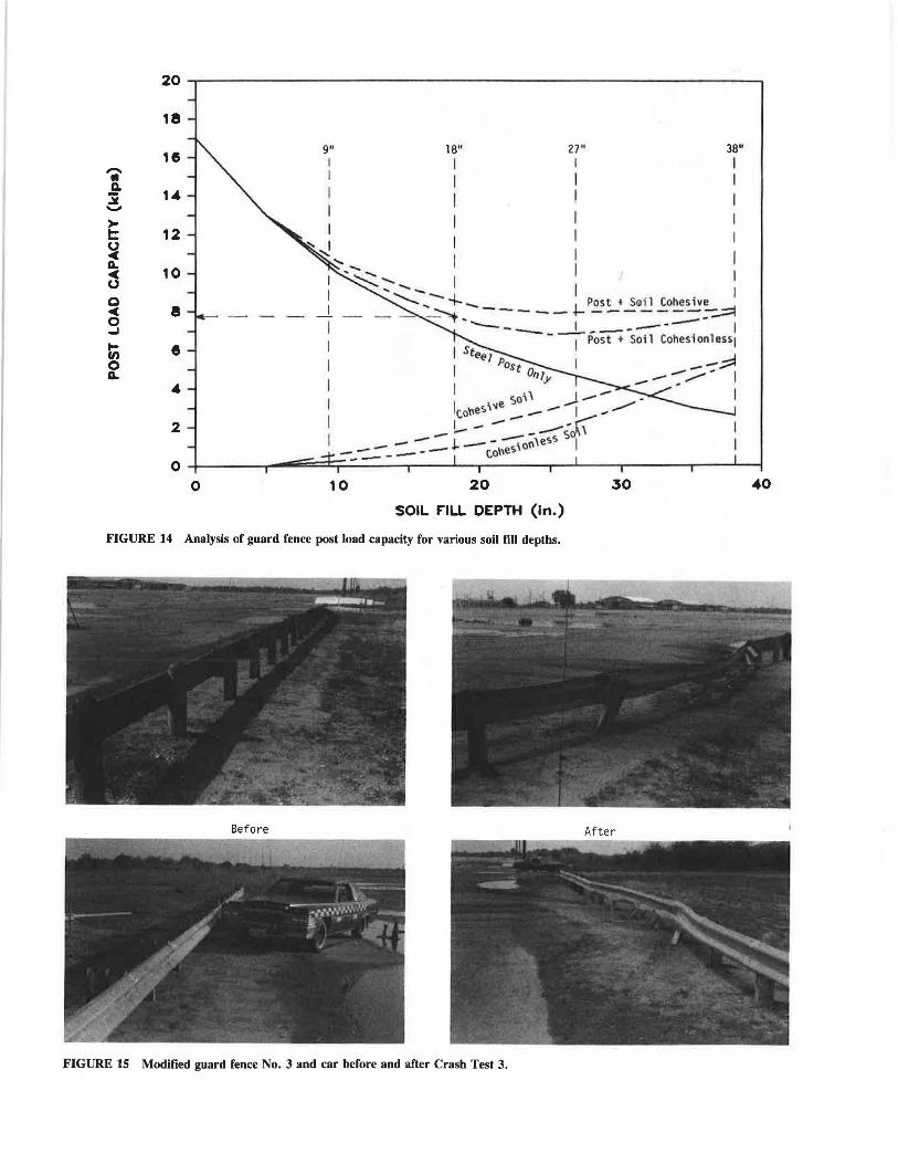
Figure 14 presents the results of an analysis of how the guard fence post load capacity would change with different soil fill depths. The 18-inch fill depth was chosen for this test because the load capacity is low (about 7.8 kips) and the probability of the car tire snagging a post is highest with low fill depths. At 37 inches, the post plus soil strength will be about 8 kips static load. The Effects of Embedment Depth, Soil Properties, and Post Type on the Performance of Highway Guardrail Posts (2) showed the dynamic load factor of such posts in soil is about 4 when impacted at 15 to 20 mph. This means the dynamic strength of this post is about 32 kips. At a 4-inch embedment, the strength of this post is about 14 kips static load. The Effects of Embedment Depth, Soil Properties, and Post Type on the Performance of Highway Guardrail Posts
(5) showed that the dynamic load factor of such steel posts alone is about 2. This means the dynamic strength of such posts with little to no soil embedment is about 28 kips. Therefore, the impact strengths of these posts at various soil embedment depths are close to each other (28 kips to 32 kips).
A typical guardrail post has a static strength of about 5.5 kips and a dynamic load factor of 4.5 (2). Therefore, the guardrail's dynamic impact strength is 5.5 kips times 4.5, or about 25 kips. Since all these posts have similar impact strength (25 to 32 kips) and deformation characteristics (deflect a foot or more), there should be no transition problems.
Crash Test 3
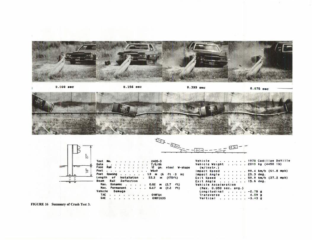
Figure 15 shows the modified guard fence No. 3 and car before and after Crash Test 3. The 4,450-pound Cadillac Deville impacted the guard fence at 61.8 mph and 25.3 degree angle. The car was smoothly redirected as intended. The maximum rail deflection was 2. 7 feet, and four posts were severely damaged. This flexible behavior is almost identical to that of the guardrail, indicating there should be no transition problem.
20
18
HS -• Ii. 14 :; ->
9" 18" 27" 38" I I I I I I I I I I I I
t: 12 0 ~ a.
10 ~ 0 0 ~ e - - -0 ...I ... e UJ 0 a.
4
2
0
I I I I
, ..... I I ~'::.' ..... _ I I I
:---...._ ... ~ ______ .j.... P~~+ ~~il ~o~~e ::.;:::I - ,., --_____ __j______ I
I Post + Soil Cohesion 1 ess1
II Stee1 Post --;;::l o -- __..- I n1;- .- _ ~
I ., I - I SO' -
lc,o\'les\"e - - I - _,,,.. I .-.- .;...--- - - ---sari'
- - - .1- -- -:\011'ess I --"".:- - - - - c,one~
0 10 20 30 40
SOIL F'ILL DEPTH (In.)
FIGURE 14 Analysis of guard fence post load capacity for various soil fill depths.
Before After
FIGURE 15 Modified guard fence No. 3 and car before and after Crash Test 3.
0. 000 sec
~ ... , ....
II 1• Jt 11
,_ N
Co
FIGURE 16 Summary of Crash Test 3.
Test No. Date • Face Rail Po1t Polt Spacing
0.156 sec
l ength of ln1tallation Beam Rail Deflection
Hax. D'namic Hax. Permanent
Vehicle Damage TAE SAE
0.399 sec
-fl-0_ /:l:"r-.. __ ft8-~ B rtB . · ---:=::4 • '
2405-3 Vehicle 1978 Cadil l ae DeVille 7/8/86 Vehicle Weight .. , 201 9 kg (4450 I b) 12 ga. steel W-1hape Cw/instr . )
W6x9 Impact Speed 99.4 km/h (61. 8 mph) 1.9 m (6 ft ·3 in) Impact Angle 25.3 deg. 53.3 m (175ft) Exit Speed . 59.9 km/h (37.2 mph)
Exit Angle 15.6 deg. 0.82 m (2.7 ft) Veh i cle Acceleration 0.67 m (2.2 ft) (Hax. 0.050 sec. avg . )
long i tudinal -2. 78 g 01RFQ4 Transverse 4. 59 g 01RFES35 Vert i cal -3. 43 g
Hirsch and Beggs 73
10 .--~~~---:~~~~---:-~~~~---:-~~~~-:-~~~~--,-~~~~--,-~~~~
z 8 ~ .... -' .... u u < -' < z -0 => 1--Cl z 0 -'
I !,
. . 5 ............ .......... , ..... .. ..... ___ ., ..... , ..... _, ·-··--.. ..
. . ·•••• •• U•••• : •• '•• ••• •• ••••••• ••• •: •
I I Max. O.j050 sec Av~ . -2.78 g !
-10 '--~~~~---~~~----~~~~~~~~~----~~~~----~~~~~~~~~
o.oo 0.10 0.20 o.3o o~o o.5o 0.60 0.10
TIME (SECONDS)
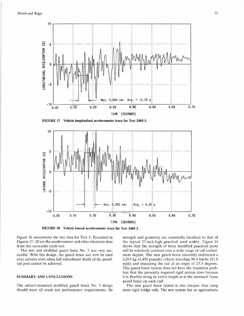
FIGURE 17 Vehicle longitudinal accelerometer trace for Test 2405-3.
z 0 -I-< c< .... _, ... u u < -' ~ ... 1-
10
5 ........
0
:5 -5 .. .. I .. ........................... .... r ..................... r Max. Q.050 sec I Avg. 4.591 g I
-10 L--~~~--'-~~~~-'----~.~--~-~_-.=-_-_-:.._-_-_--'-_~~~~-'--~~~~'--~~~-'
0.00 0. 10 0.20 0.30 0.40 0. 50 0.60 0.70
TIME (SECONDS)
FIGURE 18 Vehicle lateral accelerometer trace for Test 2405-3.
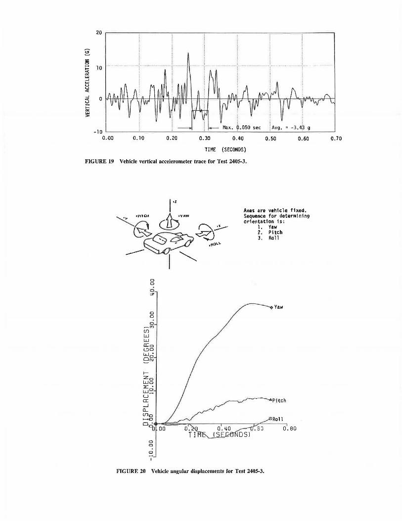
Figure 16 summarizes the test data for Test 3. Presented in Figures 17-20 are the accelerometer and other electronic data from this successful crash test.
This test and modified guard fence No. 3 was very successful. With this design, the guard fence can now be used over culverts even when full embedment depth of the guardrail post cannot be achieved .
SUMMARY AND CONCLUSIONS
The culvert-mounted modified guard fence No. 3 design should meet all crash test performance requirements. Its
strength and geometry are essentially identical to that of the typical 27-inch-high guardrail used widely. Figure 14 shows that the strength of these modified guardrail posts will be relatively constant over a wide range of soil embedment dep~hs. The new guard fence smoothly redirected a 2,019 kg (4,450 pounds) vehicle traveling 99.4 km/hr (61.8 mph) and impacting the rail at an angle of 25.3 degrees . This guard fence system does not have the transition problem that the presently required rigid system does because it is flexible along its entire length as is the standard Texas guard fence on each end.
This new guard fence system is also cheaper than using more rigid bridge rails. The new system has an approximate
~ .... ~ ..... ...J ..... u u <
10 ..
Ci! 0 u .... ~ ..... >
-10 0.00 0.10
Max . ~. 050 sec -3.4? g
0.20 0.30 0.40 0.50 0.60
TIME (SECONDS)
FIGURE 19 Vehicle vertical accelerometer trace for Test 2405-3.
0 0
0 :::2'
0 0
0 ~m
(/)
w w CI:o l:)O w. ~~ ~
' Zo Wo :E • LU~ u a: __J
CL (f)o .._,o 0.
9J
0 0
0
00
Axes are vehicle fixed. Sequence for determining orientation 1s:
1. Yaw 2. Pitch 3. Roll
Yaw
P1tch
Roll
0.80
FIGURE 20 Vehicle angular displacements for Test 2405-3.
0.70
Hirsch and Beggs
installation cost of $17 per foot as opposed to the $35 per foot cost of typical TIOl steel bridgerail.
ACKNOWLEDGMENTS
This research study was conducted under a cooperative program between the Texas Transportation Institute, the Texas State Department of Highways and Public Transportation (SDHPT), and the Federal Highway Administration. John J. Panak (Bridge Design Engineer, SDHPT) and Harold Cooner (Engineer of Geometric Design, SDHPT) were closely involved in all phases of this study.
REFERENCES
1. Standard Specifications for Highway Bridges, Thirteenth ed., American Association of State Highway and Transportation Officials, Washington, D. C. , 1983.
2. D. W. Eggers and T. J. Hirsch. The Effects of Embedment Depth, Soil Properties, and Post Type on the Performance of
75
Highway Guardrail Posts. Research Report 405-1, Texas Transportation Institute, Texas A&M University, College Station, Tex., Aug. 1986.
3. Jarvis D. Michie. NCHRP Report 230: Recommended Procedures for the Safety Performance Evaluation of Highway Appurtenances. TRB, National Research Council, Washington, D.C., March 1981.
4. J. F. Dewey, J. K. Jeyapalan, T. J. Hirsch, and H. E. Ross. A Study of the Soil-Structure Interaction Behavior of Highway Guardrail Post. Research Report No. 343-1, Texas Transportation Institute, Texas A&M University, College Station, Tex., July 1983.
5. Althea Arnold and T. J. Hirsch. Bridge Deck Designs for Railing Impacts. Research Report 295-lF, Texas Transportation Institute, Texas A&M University, College Station, Tex., Nov. 1983.
The contents of this report reflect the views of the authors, who are responsible for the opinions, findings, and conclusions presented herein. The contents do not necessarily reflect the official views or policies of the Federal Highway Administration. This report does not constitute a standard, specification, or regulation.