Embed Size (px)
Citation preview
New Developments Predicting Low Silica in Process Piping Using Handheld X-ray
Fluorescence (XRF) Presented to: NDT in Canada conference
Presented by: Mark Lessard
Business Development Manager
ThermoFisher Scientific [email protected]

Presentation Outline • Purpose of presentation:
Describe specific types of corrosion seen in piping systems and how elemental analysis may be used to prevent failures caused by these corrosion mechanisms.
• Presentation Outline
– Introduction-Corrosion Failures in Oil and Gas
– Sulfidation / Sulfidic Corrosion
– Elemental Analysis and Positive Material Identification (PMI)
– Principals of XRF
– Advances in handheld XRF
– PMI tools for Sample Preparation
– Interactive Demonstration of XRF
– Questions and Answers

Introduction: Corrosion Failures in Process Piping
• 41% of the largest losses in the hydrocarbon processing industry resulted from failures in piping systems.
• Corrosion is one of the leading causes of piping failures.
• OSHA’s National Emphasis Program (NEP) includes positive material identification (PMI).
• “Recognized And Generally Accepted Engineering Practices” or “RAGAGEP”
– Example RAGAGEP for PMI:
• API RP 578, Material Verification Program for New and Existing Alloy Piping Systems, Section 4.3
• CSB, Safety Bulletin – Positive Material Verification: Prevent Errors During Alloy Steel Systems Maintenance, BP Texas City, TX Refinery Fire
Second International Symposium on the Mechanical Integrity of Process Piping
January 1996, Houston, TX, USA

Sulfidation/Sulfidic Corrosion • Two mechanisms:
– Hydrogen-free sulfidation
– H2/H2S Corrosion
• Result of naturally occurring sulfur compounds found in crude oil.
• Causes accelerated corrosion in steel fittings, piping, heater tubes, and pressure vessels when the oil is heated for separation.
• A significant cause of leaks and failures of piping systems within the refining industry.

Sulfidation/Sulfidic Corrosion • The rate of sulfidation corrosion is a function of many factors including;
– Temperature
– Total sulfur concentration in the oil
– Types of sulfur compounds present
– Type of steam (light gas or heavy oil)
– Velocity
– Heat transfer conditions
– The presence or absence of hydrogen
– The material of construction
Prevention of Sulfidation Corrosion through Elemental Analysis
Hydrogen Free Sulfidation
– Increasing chromium content has a substantial effect of lowering the rate of sulfidation
– When carbon steel components are exposed to hydrogen-free sulfidation, those components with low Si content (<0.10%) may corrode at a significantly higher rate ( API 939-C )
H2/H2S Corrosion
– Carbon and low-alloy steels are ineffective in combating sulfidation below alloying levels of 12Cr-1Mo
– It is most common to use 18Cr-8Ni (300-series stainless) or higher alloyed steels in these environments
In-Situ Elemental Analysis of Piping Systems
2 Primary Technologies for Portable Analysis:
• Optical Emission Spectroscopy (OES)
– Technique of vaporizing sample surface and analyzing the emitted light spectra. The wavelength of the light corresponds to the elements present, while the intensity is a function of quantity of that element.
• X-ray Fluorescence Spectroscopy (XRF)
– Technique of exciting and ejecting atoms’ inner shell electrons with x-ray radiation and analyzing the fluorescent x-rays emitted when the atoms return to a stable state. X-ray energies emitted correspond to the individual elements, while the intensity is a function of quantity.

Handheld X-ray Fluorescence Spectroscopy Pros:
• Accurate
• Portable
– The handheld XRF analyzer weighs approximately 1.3 kg (3 lbs.) and is transported in a belt holster at the user’s side
• Reduced sample preparation
• Completely nondestructive
• Simplicity
– XRF technology is much more user-friendly, allowing relatively unskilled operators to participate in the inspection process
Cons:
• Can measure elements only down to Mg on the periodic table (cannot do carbon)
• Stricter regulation and licensing requirements

How the XRF Works
Each individual element produces its own set of characteristic x-rays; the basis for qualitative analysis
By counting the number of
characteristic x-rays of a given element we can determine its concentration; the basis for quantitative analysis

• Since late 1960s, XRF has evolved through 7 generations; each generation has added new measurement capabilities as indicated by the (3) groups below
– Smaller , Faster , Better performance & Easier to use • Today, nearly all alloys can be tested with these powerful tools. This addresses PMI
Concerns in the Upstream /Downstream & Transportation Markets
XRF Evolution in Performance
Measured (1) Element
at a time to:
>= 1.00% Chemistry in
>/= 1 to 2 minutes
Measured ( 16 to18 )
Elements at a time to:
>= 0.01% Chemistry in
</= 30 to 60 seconds
Measures ( 25 to 30 )
Elements at a time to:
>/= 0.003% Chemistry
</= 3 to 12 seconds
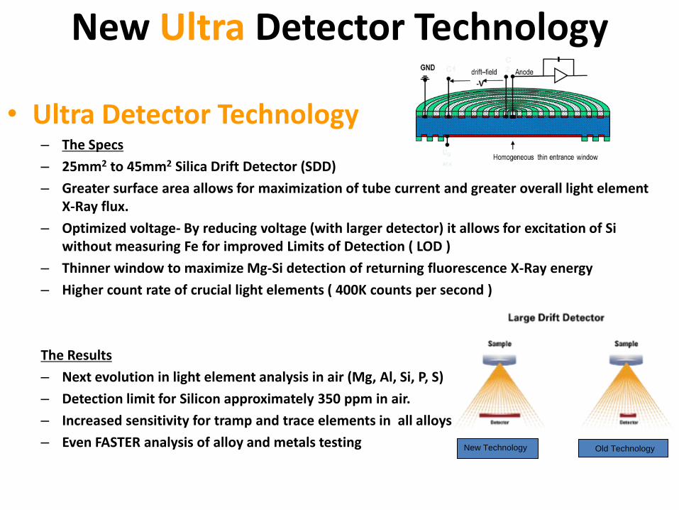
New Ultra Detector Technology
• Ultra Detector Technology – The Specs
– 25mm2 to 45mm2 Silica Drift Detector (SDD)
– Greater surface area allows for maximization of tube current and greater overall light element X-Ray flux.
– Optimized voltage- By reducing voltage (with larger detector) it allows for excitation of Si without measuring Fe for improved Limits of Detection ( LOD )
– Thinner window to maximize Mg-Si detection of returning fluorescence X-Ray energy
– Higher count rate of crucial light elements ( 400K counts per second )
The Results
– Next evolution in light element analysis in air (Mg, Al, Si, P, S)
– Detection limit for Silicon approximately 350 ppm in air.
– Increased sensitivity for tramp and trace elements in all alloys
– Even FASTER analysis of alloy and metals testing
New Technology Old Technology

How Filters in XRF Automatically Work the Element Range in
the Periodic Table
“ Low Filter “engaged
Automatically for :
Ti ,V , Cr
“ Main Filter“ engaged
Automatically for :
All Elements
“ Light Filter “engaged
Automatically for :
S, P, Si, Al, Mg
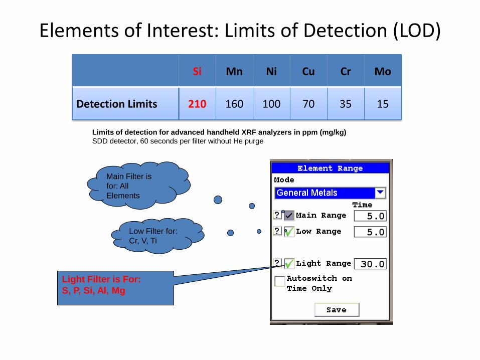
Elements of Interest: Limits of Detection (LOD)
Si Mn Ni Cu Cr Mo
Detection Limits 210 160 100 70 35 15
Limits of detection for advanced handheld XRF analyzers in ppm (mg/kg)
SDD detector, 60 seconds per filter without He purge
Low Filter for:
Cr, V, Ti
Light Filter is For:
S, P, Si, Al, Mg
Main Filter is
for: All
Elements

Existing Piping Systems ( Retro-Active PMI ) Programs :
Priority for API RP 578 2nd Edition – “High Temperature Sulfidic Corrosion - API RP 939-C” • Process Units Susceptible to Sulfidation:
– Carbon Steels with low silicon (0.10%) content can corrode at an accelerated rate – Assets at risk from this type of degradation should apply PMI control to determine
Silicon levels. (Retro-Active PMI is suggested and to follow API 578.) – See API 571 and API RP 939-C – See Section 7.1.4 & 5
Low Si-33%,PMI-18%,Specification Break-17%
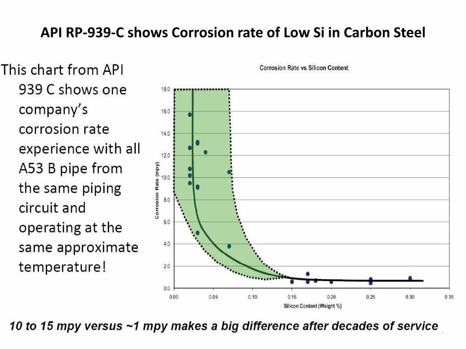
API RP-939-C shows Corrosion rate of Low Si in Carbon Steel

Measuring Low Si in the field has some Requirements
• Current Technologies both ( XRF/OES) have limits for the Process Temperature Range.
• Proper Sample preparation is required.
• Most material of concern for Sulfidation is Carbon Steel piping installed before 1985. This material was usually double/tripled stamped ( A53/A106/API 5LB,& A285 Plates )
• Typically, fittings have higher Si content where piping straight runs have less Si.
• Specification breaks are also a contributing factor ( 5Cr welded to 9Cr )
• Other Concerns for high temperature process ( 650 F and greater ) is using 5 Cr and 9Cr with both low Cr & Si.

Sample Preparation for Low Si Measurement
• Typical metal alloys used in the petrochemical industry will oxidize when exposed to atmospheric conditions. This oxide coating can affect the accuracy of the reading when performing an XRF analysis and must be removed.
• Sample contamination can occur if you prepare with the wrong abrasive disc. It is recommended to use grinding discs made from zirconium aluminum oxide. Zirconium is a metal not commonly found in steel alloys, so trace amounts found on the surface will not negatively affect test results.
• As a recommended starting point, the following grit sizes are suggested:
• Stainless Steel – 120 grit
• Cr/Mo Steel – 80 grit
• Carbon & Low Alloy Steel – 60 grit.

Thank You
Interactive Demonstration
And Questions?
My contact details
Mark Lessard
Business Development Manager
Thermo Scientific
Portable XRF Analyzers
2 Radcliff road
Tewksbury, MA 01876 USA
(T) 978-215-1315