Embed Size (px)
Citation preview
Use of simulation in the production of cast aluminium wheels
Bernd Meurer, Dirk Haferkamp and Alexander Jörg
Dr. B. Meurer, Dipl.-Ing. D. Haferkamp and Dipl.-Ing. A. Jörg, Michelin Kronprinz
Werke GmbH, Solingen.
Introduction
Recent years have seen a considerable increase in the market share of cast
aluminium wheels for new passenger cars. The decisive factor is not only a
technical advance through weight saving by comparison with steel wheels. The
designer also uses the possibility of positively changing the overall appearance of
the vehicle. Additionally, the cast wheel not only enables the fashioning of a
vehicle according to the individual taste of the customer but also the revaluation
of a special series, e.g. with stagnating sales of a particular series. There is also a
trend towards the largest optical appearance of the wheels, not only in new
vehicles but also in special series. Wheels in excess of 20” diameter are no
longer exceptional.
The development tendencies lead to immense technical involvement with
regard to optimisation of weight and the production process. The wheel
manufacturer is also under pressure due to the increasing speed of model
changing and shortening of development times, i.e. „time to market“. Finally, on
account of global souring the wheel is also the subject of worldwide competition
with regard to price. To summarise, the objective is thus to as quickly as possible
develop an optimally light wheel that conforms with the specification at the lowest
possible price.
This was exactly the aim of Michelin Kronprinz Werke GmbH when in 1998 the
company, as a long-time manufacturer of cast aluminium wheels, introduced
computerised simulation for low pressure diecasting. The process employs the
MAGMASOFT software developed by MAGMA Giessereitechnologie GmbH [1].
Simulation of casting represented a substantial step towards achieving
compliance with the automobile manufacturers requirements in accordance with

ISO/TS16949. Through the prediction of possible casting defects and optimisation
of the casting process with regard to the machine process parameter, it is already
possible to pre-calculate the optimal design of the die, casting and wheel during
the development phase.
Simulation of casting operations has many more advantages. In addition to the
comparison of different types and sizes of wheels it can also provide other
process knowledge which is not directly known or measurable from the real
process. For example, the flow speeds and behaviour of the melt during die filling,
formation of the microstructure, estimation of the mechanical properties and the
internal thermal stresses in the wheel and the die.
This article explains the use of casting simulation since the introduction of the
MAGMASOFT software. Individual examples are used to look at special casting
defects that can be mapped with simulation and avoided through optimisation.
The results are compared with and confirmed by production experience and those
published in the literature [2 to 5].
Production process, construction and potential defects of a cast wheel
Production of a cast wheel starts with the melting of the charge material and a
usual melt treatment. In general, AlSiMg with T6 heat treatment and AlSi11
aluminium silicon alloys are used. The molten aluminium is then filled into the
casting machine crucible furnace. An individual low pressure die is mounted on
the machine for each type of wheel, the later design side of the wheel being at the
bottom.
Figure 1 shows the arrangement of a low pressure die. The multi-component
die consists of bottom cores as well as up to four moveable lateral slides and a
top core and is heated up to 400 °C. According to the wheel geometry and die
design it is equipped with several independently adjustable cooling circuits, not
only in the bottom but also in the top core.
The die is filled with melt by means of pressure from the crucible furnace
located underneath it. This rises via the feed tube and the gate sleeve through a
metal sieve and thence into the die cavity along the hub and spokes up to the rim.
The cooling circuits are already switched on at defined times during and after die
filling, whereby the pressure from the crucible also remains after filling in order to
maintain feeding. After opening of the lateral slide, the wheel that has shrunk onto
the top core is lifted from the die through raising of the core and mechanically
ejected onto a slewing plate. Whilst the die is open a new sieve is laid into the
gate funnel before it is closed and the next wheel cast.
The die filling is very much dependent on the wheel geometry. Figure 2 shows
the pressure curve as a function of the process time for a 7J×16 thin-spoke cast
wheel. The process time can be divided into four different parts:
a) die filling;
b) pressure holding time;
c) cooling time without pressure;
d) removal of the wheel and die maintenance.
The actual filling of the die only takes a few seconds, after which the wheel
solidifies during the pressure holding time. After falling below the coherency
temperature, i.e. the temperature at which the dendritic network is formed,
feeding is no longer possible. In the course of further cooling to solidus
temperature the danger of distortion of the wheel during removal is reduced and
further heating of the die avoided.
The raw castings are then subjected to further processes.
• Deflashing and optical inspection whilst still at the casting machine
• 100 % X-ray inspection
• If necessary, T6 heat treatment
• Mechanical machining
• Deburring and checking (density, out-of-balance)
• Surface treatment (powder coating and painting)
A large percentage of problems occurring with cast wheels is caused by casting
defects, only a small part of which can be determined optically or by X-ray directly
after the casting process. Under certain circumstances individual defects only
become detectable after mechanical machining, surface coating or diverse
checks.
On account of the geometry and wall thickness ratios, the solidification rate
varies in different areas of the wheel. If with unfavourable geometrical conditions
the volume deficit occurring at the change between the liquid and solid phase can
no longer be fed, this results in so-called shrinkage porosity.
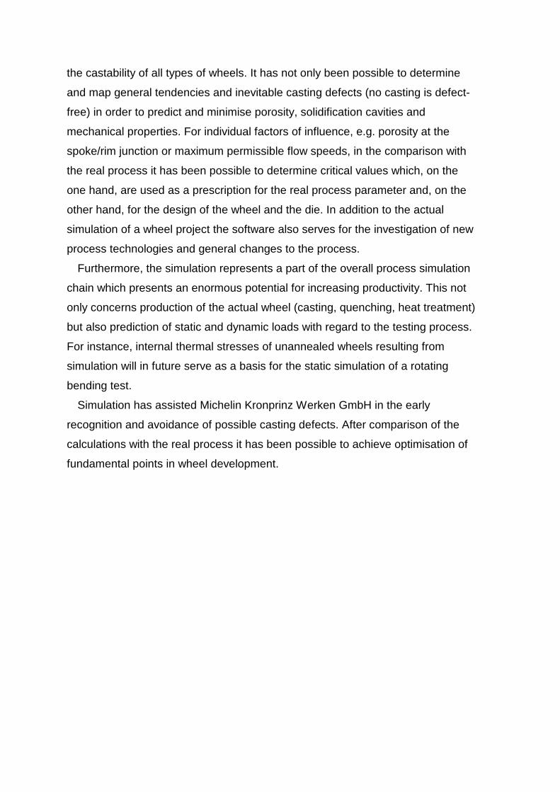
The following typical defects in a cast wheel are (Figure 3):
• Oxide inclusions and solidification cavities in the rim area (a) lead to pressure
loss of the wheel/tyre unit.
• Shrinkage porosity occurs at the junction between spoke and rim (b).
• Shrinkage porosity in the hub area (c) briefly occurs at times during the process
if the cooling in the centre area is no longer sufficient.
• Fast filling velocities lead to turbulent die filling and defective ventilation of the
die to air inclusions and oxide formation [3]. Both effect the porosity [3], the
service life [6] and the surface quality of the rim.
On account of the commercial aspects with large series production, pre-
determination of the optimum process parameter and ideal design of the casting
geometry, finished part geometry and the complete layout of the die for a cast
wheel becomes more and more important with increasing size of the wheel:
• Longer die filling paths increase the risk of shrinkage porosity and porosity in
the rim area.
• The process times are longer, on account of the heavier raw casting
• The percentage of scrap increases with an unchanged size of the casting
machine holding furnace and the associated less number of castings per
charge.
• With heat treated wheels there is a greater risk of distortion, so that the
percentage of extra material for mechanical machining becomes higher.

Simulation
The prerequisite for simulation of low pressure die casting is simulation of the
real casting process itself, the major effort being concentrated on the compilation
of the models for wheel and tool and the input of all necessary process
parameters. The data of the wheel geometry, the machining allowances, the die
and the cooling compiled by CAD are imported via the STL interface by means of
MAGMASOFT. After generation of the network and entry of the approximated
casting parameters, the actual calculation of die filling and solidification is carried
out for several cycles.
Results and analysis of simulation
The main points of the calculations are the investigation and forecasting of the
castability of a wheel under the given geometrical and calculatory aspects
(number of castings, scrap rate) in order to achieve series cast wheel production
in accordance with customer specifications at the first attempt. In a first
calculation stage the die filling and solidification simulations are carried out with
standardised process parameters. Because real process parameters, e.g. pouring
temperature, process time, pressure build-up, cooling duration, are not yet
available at this point, the values used for the calculation are based on
experience and analyses of real wheel projects and comparison of simulations
already carried out on similar wheels. In the light of the results of the simulation, if
necessary, optimisation stages are undertaken in a second stage, which may not
only concern the geometry of the wheel and die but also the process parameter.
DOE (Design of Experiment) methods are used for reduction of the number of
attempts and also the simulations respectively.
Die filling
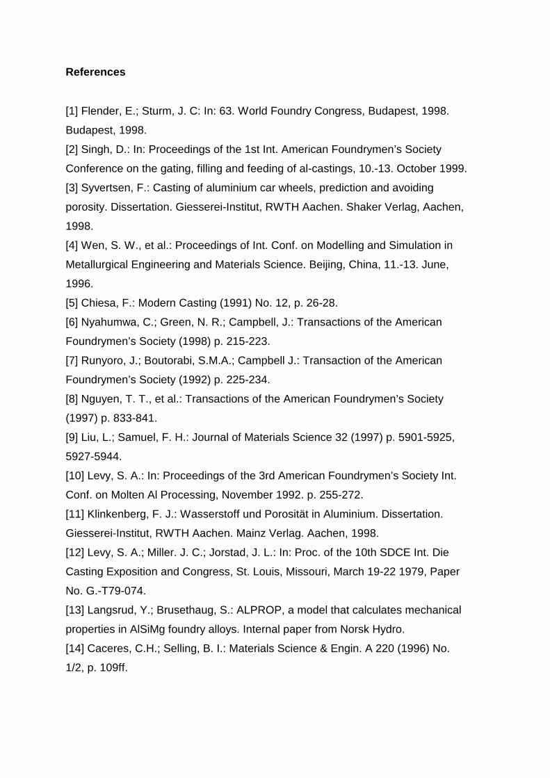
The relationship of the calculated maximum flow speeds to the degree of die
filling is shown in Figure 4 by the example of a 7J×16 cast wheel. The values of
the maximum flow speeds are standardised to the highest values at the beginning
of die filling. Nevertheless, as also with the following figures, these values do not
show the maximum flow speeds at the front of the melt or at a local point but are
values that can occur at arbitrary positions in the component. In general, this can
be divided into three phases, as shown in the example of the selected wheel with
a filigree spoke shape (Figure 4):a) Start of die filling: With entry of the melt into the die cavity the maximum flow
speed goes down because the volume of the die cavity increases.
b) Start of filling of the spokes: With the reduction of the feed cross-section in the
relatively thin spokes the melt locally accelerates in this region.
c) Start of rim filling: On reaching the larger volume with entry into the rim region
the maximum speed of the melt again reduces until the wheel is completely
filled.
An important prerequisite for good cast quality of an aluminium wheel is optimal
die filling whilst avoiding turbulence of the melt [2, 3, 7, 8]. Only phase (a) in
Figure 2 is of decisive importance for the actual die filling, the further sections of
the process only serve for backup feeding (b) and solidification (b to d). In phase
(a) the flow speeds increase with an increase in the build-up of pressure, so that
there is also a greater risk of turbulence during die filling. Fundamental tests show
that flow speeds in excess of 0.5 m/s result in breaking up of the melt front [7] (by
comparison with this, on account of model simplification, the calculated critical
limit is higher). Breaking up of the melt leads to new oxidation of the melt front
and to the inclusion of oxide skins. These oxides predominantly consist of Al2O3
and MgO spinels [9] and have a considerable effect on the surface quality.
Results of service life tests are also negatively influenced by turbulent die filling
[6] because of the increase in the probability of the formation of aluminium and
magnesium oxides near to the surface, cracks frequently commencing at these
surface defects. Furthermore, tests [10] show that the problem of porosity of cast
aluminium wheels is strongly dependent on oxide and other metallic and non-
metallic inclusions.
Calculations for two different pressure build-up curves for a wheel with solid
spokes resulted in a laminar and a turbulent die filling. The flow profiles show
clear differences (Figure 5). This shows the maximum flow speeds as a function
of the filling time for both variants. The die filling states on achieving maximum
flow speeds are also shown. The absolute maximums of both calculations show
only very little difference. The more important factor is the different magnitudes of
the high speed areas and the point in time of their occurrence.
A laminar cast wheel already exhibits maximum flow speed after a relatively low
50 % of the filling time. At this time the spokes are only partially filled. Nearly all of
the surface of the melt in the die has contact with the ambient air. The maximum
flow speeds only occur in the middle area of the wheel, where there is increased
danger of the formation and entry of oxides. If they do form, they are not
transported into the rim but predominantly collect on the back of the spoke and in
the middle area. As shown in the following, the total area of high flow speeds is
small when compared with a turbulently cast wheel.
With turbulent die filling the maximum flow speed is achieved at a relatively
later 80 % of the filling time. In this case, the spoke and hub areas are already
completely and the rim almost half-filled. The melt front in the rim area is wave-
shaped (Figure 5). The only contact with air is at the melt front in the rim area.
The maximum flow not only occurs in the middle area, where with complete filling
of the die cavity entry of air is no longer possible, but also in the rim area.
Particularly here the high speeds occur over longer times by comparison with
laminar cast wheels. For this reason, there is a considerably greater probability of
breaking down of the melt front and the inclusion of oxides, resulting in an
increase in porosity in the rim area. With turbulent die filling higher flow speeds
are reached over longer periods than with a laminar filled wheel. The results of
the calculations for this wheel were confirmed in reality.
In the comparison of the calculated maximum flow speeds for different types of
wheel, dependent on the wheel size, design and process parameter, there were
clear differences in the flow conditions (Figure 6). The figure shows the
calculated maximum flow speeds of different wheels (size, design) and different
process parameters (wheel 1a and 1b) at the beginning of die filling (10 % filling
ratio). At this point in time only the middle area of the wheel is full. Calculated
critical thresholds of the flow speeds are about 80 % of the maximum flow rates in
relationship to wheel 1a. The characteristic factor for wheel 1 is the great
difference in level between the hub and the lowest point of the spoke (top-
casting). The design of wheel 2 is such that the melt rises from the gate to the
rim. In spite of the same pressure build-up and the same wheel size, wheels 1a

and 2 exhibit considerably different maximum flow speeds. The risk of surface
problems and porosity is thus considerably less for wheel 2.
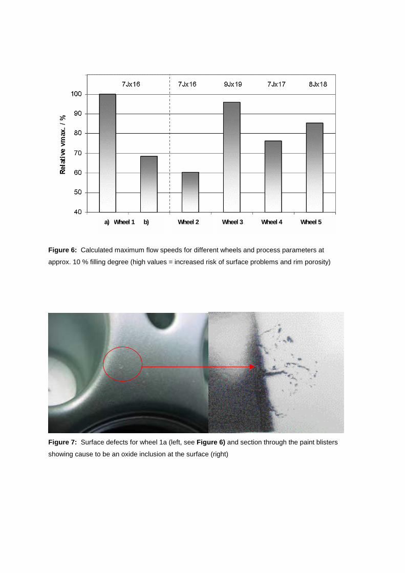
For wheel 1a the calculated flow speeds are high; comparative casting tests
resulted in surface problems. A material test clearly showed that this was due to
oxides near to the surface. Figure 7 shows such a defect and a microscopic
section of it. Small changes to the die and particularly reduction of the flow
speeds (through a slower pressure build-up) enabled the avoidance of this defect.
Wheel 1b in Figure 6 shows that the maximum flow speeds are in excess of 30 %
lower than the initial version (wheel 1a).
Contrary to this, on account of the design, wheel 2 exhibits only low and non-
critical flow speeds.
Calculations and tests show that laminar die filling not only positively influences
the surface quality but also reduces the risk of porosity (see explanation to
Figure 5).However, there are limits to the optimisation of the filling process because the
complete thermal condition of the die must simultaneously be taken into account
as a peripheral condition. Too slow die filling increases the risk of freezing by
decreasing the melt temperature below the alloy-dependent coherence
temperature. However, the calculations show no evidence of solidification cavities
caused by this on account of the premature freezing of the melt.
Calculations with MAGMASOFT allow the direct comparison of critical
parameters, e.g. flow speeds, that cannot, or only with difficulty, be measured
during the process and enable a comparison independent of the wheel design.
This means that it is not only possible to optimise the design of the casting and
the die but also, for example, to define the input parameter for the pressure build-
up curve on the casting machine.
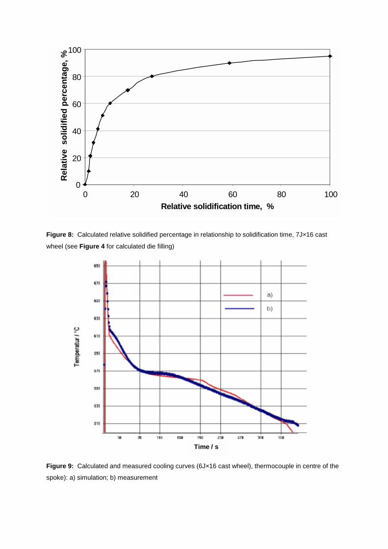
Solidification and cooling curves
During and after completion of die filling the wheel starts to solidify. Figure 8explains the relationship between the solidified percentage of the total volume of
the cast wheel and the solidification time. 80 % of the wheel has already solidified
after a max. 30 % of the process time. At this point in time the majority of the
residual melt is in the middle area of the wheel. The illustrated solidification time
is thus a part of the total process time (see Figure 2). Ideally, solidification should
occur directionally, starting from the rim, via the spokes to the hub. In this case,
the main potential for increasing productivity and thus reduction of the process
time lies in optimisation of the cooling and the die design in the middle area of the
wheel.
For investigation of the process times the calculated and measured cooling
curves at points in the wheel and die were compared. Figure 9 shows the good
agreement between simulation and measurement of the cooling curve by a
thermocouple placed in the wheel spoke. The differences between all calculated
and actual cooling times and thus also the process times are less than 10 %. This
is on the one hand due to model simplification (heat transmission coefficients,
formation of air gaps, shrinking, pouring parameter, cooling) and, on the other
hand, to the actual measuring difficulties (contact between thermocouple and
metal).
Consideration of the cyclical casting process is important for series production.
The thermal condition of the die, which is for example influenced by interruptions
or filling of the casting machine, has a decisive influence on the resultant casting.
Figure 10 shows the achievement of a stable process parameter, i.e. constant
solidification time with constant casting quality, in relationship to the initial
temperature and number of cycles. For an initial 250 °C die, theoretically up to 10
cycles are necessary in order to achieve stable process conditions. The right-
hand part of Figure 10 shows the peak temperatures of a thermocouple in the
bottom core. Here, stable conditions already occur after four cycles
(measurements a few millimetres away from the surface). This shows that the
temperature control of the die reacts completely unsensitively and thus provides
only a small indication of the wheel quality. With an ideally preheated die stable
conditions are already achieved after 2 to 3 cycles. The calculation shows that, in
the case of a cold die, stable process conditions are more rapidly achieved when
the start-up process is run with shorter cycle times, and the following heating of
the die controlled with a successively lengthened cycle time until stable conditions
are achieved [3].
Microstructure and mechanical properties
In addition to the alloy composition and heat-treatment [10, 12], the assessment
and prediction of the microstructure are very strongly dependent on the
solidification conditions, which can vary considerably in accordance with the
wheel design. The formation of the microstructure is however decisive for the
mechanical properties of the material. The dendrite arm spacings calculated with
MAGMASOFT are used for estimation of the secondary dendrite arm spacing.
Measurements of the relationship between the secondary dendrite arm spacing
and the mechanical properties of AlSi7Mg [13] and the further worsening of these
with increasing damage to the microstructure on account of the sum of inclusions
and intermetallic phases [14] serve for estimation of achievable elongations on
fracture, which are in good agreement with measurements.
Consequently, a wheel with a thinner spoke solidifies faster, has a finer
microstructure and thus better mechanical properties than a wheel with a
massive, thick spoke (Table 1). The 3 % elongation specified for the spoke in
wheel 7 is thus more difficult to achieve than it is for wheel 6. For this reason, in
contrast to real specifications, it is generally more sensible and desirable that
mechanical properties such as elongation on fracture are not contained in the
specification for individual areas, e.g. position of sample in the spoke but,
analogous to other materials, in dependence of the wall thicknesses.
The influence of a relatively cold die at 250 °C on the microstructure and the
mechanical properties is shown in Figure 11. If the „cold“ die heats up to stable
conditions in the course of a few cycles, as in the case after an interruption or
refilling of the pouring furnace, on account of the slower solidification of the
microstructure with an increasingly hotter die, the secondary dendrite arm spacing
increases. In the stated case this can lead to a 20 % coarsing of the
microstructure, this being associated with the expectation of a 50 % reduction in
elongation on fracture. Simulation enables estimation of the achievable formation
of the microstructure and thus of the mechanical properties.
Summary and conclusion
The introduction of simulation with MAGMASOFT has widely led to optimisation
of the wheel and die design as well as the process parameters. On account of the
similarly of the products, simulation offers the possibility of good comparability of
the castability of all types of wheels. It has not only been possible to determine
and map general tendencies and inevitable casting defects (no casting is defect-
free) in order to predict and minimise porosity, solidification cavities and
mechanical properties. For individual factors of influence, e.g. porosity at the
spoke/rim junction or maximum permissible flow speeds, in the comparison with
the real process it has been possible to determine critical values which, on the
one hand, are used as a prescription for the real process parameter and, on the
other hand, for the design of the wheel and the die. In addition to the actual
simulation of a wheel project the software also serves for the investigation of new
process technologies and general changes to the process.
Furthermore, the simulation represents a part of the overall process simulation
chain which presents an enormous potential for increasing productivity. This not
only concerns production of the actual wheel (casting, quenching, heat treatment)
but also prediction of static and dynamic loads with regard to the testing process.
For instance, internal thermal stresses of unannealed wheels resulting from
simulation will in future serve as a basis for the static simulation of a rotating
bending test.
Simulation has assisted Michelin Kronprinz Werken GmbH in the early
recognition and avoidance of possible casting defects. After comparison of the
calculations with the real process it has been possible to achieve optimisation of
fundamental points in wheel development.
References
[1] Flender, E.; Sturm, J. C: In: 63. World Foundry Congress, Budapest, 1998.
Budapest, 1998.
[2] Singh, D.: In: Proceedings of the 1st Int. American Foundrymen’s Society
Conference on the gating, filling and feeding of al-castings, 10.-13. October 1999.
[3] Syvertsen, F.: Casting of aluminium car wheels, prediction and avoiding
porosity. Dissertation. Giesserei-Institut, RWTH Aachen. Shaker Verlag, Aachen,
1998.
[4] Wen, S. W., et al.: Proceedings of Int. Conf. on Modelling and Simulation in
Metallurgical Engineering and Materials Science. Beijing, China, 11.-13. June,
1996.
[5] Chiesa, F.: Modern Casting (1991) No. 12, p. 26-28.
[6] Nyahumwa, C.; Green, N. R.; Campbell, J.: Transactions of the American
Foundrymen’s Society (1998) p. 215-223.
[7] Runyoro, J.; Boutorabi, S.M.A.; Campbell J.: Transaction of the American
Foundrymen’s Society (1992) p. 225-234.
[8] Nguyen, T. T., et al.: Transactions of the American Foundrymen’s Society
(1997) p. 833-841.
[9] Liu, L.; Samuel, F. H.: Journal of Materials Science 32 (1997) p. 5901-5925,
5927-5944.
[10] Levy, S. A.: In: Proceedings of the 3rd American Foundrymen’s Society Int.
Conf. on Molten Al Processing, November 1992. p. 255-272.
[11] Klinkenberg, F. J.: Wasserstoff und Porosität in Aluminium. Dissertation.
Giesserei-Institut, RWTH Aachen. Mainz Verlag. Aachen, 1998.
[12] Levy, S. A.; Miller. J. C.; Jorstad, J. L.: In: Proc. of the 10th SDCE Int. Die
Casting Exposition and Congress, St. Louis, Missouri, March 19-22 1979, Paper
No. G.-T79-074.
[13] Langsrud, Y.; Brusethaug, S.: ALPROP, a model that calculates mechanical
properties in AlSiMg foundry alloys. Internal paper from Norsk Hydro.
[14] Caceres, C.H.; Selling, B. I.: Materials Science & Engin. A 220 (1996) No.
1/2, p. 109ff.

Picture Index
Figure 1. Arrangement of die for low pressure die casting
Figure 2. Pressure build-up curve during low pressure casting of a wheel with a
filigree spoke geometry (7J×16 wheel): a) die filling; b) pressure holding time; c)
cooling without pressure; d) removal from die and die maintenance; e) casting of
next wheel
Figure 3. Critical areas of a cast wheel: a) porosity in rim area; b) solidification
cavities at spoke/rim junction; c) solidification cavities in hub area
Figure 4. Calculated maximum flow speeds in relationship to degree of die filling
(7J×16 wheel in Figure 2): a) start of filling; b) beginning of spoke filling; c)
beginning of rim filling
Figure 5. Calculated maximum flow speeds as a function of the filling time for
laminar and turbulent die filling, i.e. low and high pressure build-up respectively
(10J×19 cast wheel with a massive, thick spoke); the wheel sketches show the
relevant degree of filling with achievement of maximum flow speeds
Figure 6. Calculated maximum flow speeds for different wheels and process
parameters at approx. 10 % filling degree (high values = increased risk of surface
problems and rim porosity)
Figure 7. Surface defects for wheel 1a (left, see Figure 6) and section through
the paint blisters showing cause to be an oxide inclusion at the surface (right)
Figure 8. Calculated relative solidified percentage in relationship to solidification
time, 7J×16 cast wheel (see Figure 4 for calculated die filling)
Figure 9. Calculated and measured cooling curves (6J×16 cast wheel),
thermocouple in centre of the spoke): a) simulation; b) measurement

Figure 10. Effect of the start-up process with a cold (250 °C) and a hot (450 °C)
die on the solidification time and achievement of stable process conditions
Figure 11. Calculation of maximum dendrite arm spacings (DAS) in relationship
to increasing heating up and number of cycles (7J×16 cast wheel, 250 °C initial
die temperature, see Figure 10)

Figure 1: Arrangement of die for low pressure die casting
0
20
40
60
80
100
120
0 20 40 60 80 100 120
Relative process time / %
Rel
ativ
e pr
essu
re b
uild
-up
/ %
a) b) c) d) e)
Solidification
Diefilling
Figure 2: Pressure build-up curve during low pressure casting of a wheel with a filigree spoke
geometry (7J×16 wheel): a) die filling; b) pressure holding time; c) cooling without pressure; d)
removal from die and die maintenance; e) casting of next wheel
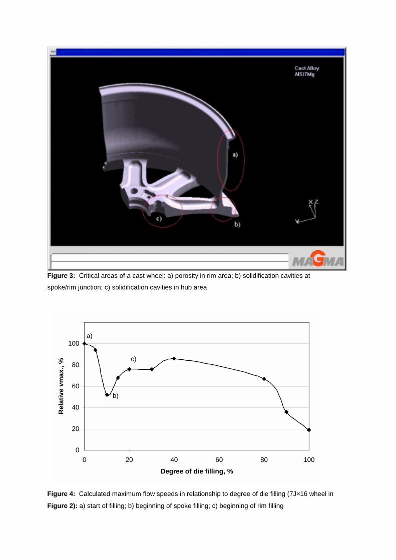
Figure 3: Critical areas of a cast wheel: a) porosity in rim area; b) solidification cavities at
spoke/rim junction; c) solidification cavities in hub area
0
20
40
60
80
100
120
0 20 40 60 80 100
Degree of die filling, %
Rel
ativ
e vm
ax.,
%
a)
b)
c)
Figure 4: Calculated maximum flow speeds in relationship to degree of die filling (7J×16 wheel in
Figure 2): a) start of filling; b) beginning of spoke filling; c) beginning of rim filling

Relative filling time, %
Figure 5: Calculated maximum flow speeds as a function of the filling time for laminar and
turbulent die filling, i.e. low and high pressure build-up respectively (10J×19 cast wheel with a
massive, thick spoke); the wheel sketches show the relevant degree of filling with achievement of
maximum flow speeds
Wheel 1a) b) Wheel 2 Wheel 3 Wheel 4 Wheel 5
Figure 6: Calculated maximum flow speeds for different wheels and process parameters at
approx. 10 % filling degree (high values = increased risk of surface problems and rim porosity)
Figure 7: Surface defects for wheel 1a (left, see Figure 6) and section through the paint blisters
showing cause to be an oxide inclusion at the surface (right)
0
20
40
60
80
100
0 20 40 60 80 100Relative solidification time, %
Rela
tive
sol
idifi
ed p
erce
ntag
e, %
Figure 8: Calculated relative solidified percentage in relationship to solidification time, 7J×16 cast
wheel (see Figure 4 for calculated die filling)
Time / s
Figure 9: Calculated and measured cooling curves (6J×16 cast wheel), thermocouple in centre of the
spoke): a) simulation; b) measurement

40
60
80
100
120
0 2 4 6 8 10No. of cycles
Solid
ifica
tion
tom
e, %
Start withcold die, 250°C
Start withhot die, 450°C
T / °C
Figure 10: Effect of the start-up process with a cold (250 °C) and a hot (450 °C) die on the
solidification time and achievement of stable process conditions
50
60
70
80
0 2 4 6 8 10No. of cycles
DA
S, µµ µµ
m
Start withcold die, 250°C
Figure 11: Calculation of maximum dendrite arm spacings (DAS) in relationship to increasing
heating up and number of cycles (7J×16 cast wheel, 250 °C initial die temperature, see Figure 10)

Wheel type Spoke Hub
DAS in µm A in % DAS in µm A in %
Wheel 6 8J×17
(thin spoke)
40 to 50 6,0 to 7,0 50 to 61 4,0 to 6,0
Wheel 7 7J×15
(thick spoke)
60 to 67 3,3 to 3,9 60 to 76 2,7 to 4,0
Table 1: Calculated secondary dendrite arm spacings (DAS) and elongation on fracture A (with max.
1 % porosity) for various wheel types