Embed Size (px)
Citation preview

Use of StreetPave for Design ofConcrete Pavements for
Cities and Counties in Minnesota
Matthew Oman, Primary Author Braun Intertec Corporation
March 2012Research Project
Final Report 2012-10

To request this document in an alternative format, call Bruce Lattu at 651-366-4718 or 1-800-657-3774 (Greater Minnesota); 711 or 1-800-627-3529 (Minnesota Relay). You may also send an e-mail to [email protected]. (Please request at least one week in advance).

Technical Report Documentation Page 1. Report No. 2. 3. Recipients Accession No. MN/RC 2012-10 4. Title and Subtitle 5. Report Date
Use of StreetPave for Design of Concrete Pavements for Cities and Counties in Minnesota
March 2012 6.
7. Author(s) 8. Performing Organization Report No. Matthew S. Oman, Amy J. Grothaus 9. Performing Organization Name and Address 10. Project/Task/Work Unit No. Braun Intertec Corporation 11001 Hampshire Avenue South Bloomington, MN 55438
11. Contract (C) or Grant (G) No.
(c) 00068
12. Sponsoring Organization Name and Address 13. Type of Report and Period Covered Minnesota Department of Transportation Research Services Section 395 John Ireland Boulevard, Mail Stop 330 St. Paul, MN 55155
Final Report 14. Sponsoring Agency Code
15. Supplementary Notes http://www.lrrb.org/pdf/201210.pdf 16. Abstract (Limit: 250 words)
The Minnesota Department of Transportation’s (MnDOT) concrete pavement design procedure, RigidPave, is based on the 1981 American Association of State Highway and Transportation Officials (AASHTO) Interim Guide and is entirely empirically-based. The American Cement Pavement Association (ACPA) developed StreetPave based on the Portland Cement Association (PCA) thickness design method with updated information, including a new fatigue model. This study compared RigidPave to StreetPave with a review of the input variables and design inputs used by surrounding departments of transportation. Existing thin (six inches or less) concrete pavements were also evaluated, which included both city and county pavements and test cells at MnROAD. There are two primary differences between the RigidPave and StreetPave: 1) traffic is handled differently and 2) the underlying design methodology. Both are based on time-tested and proven design methodologies and provide generally similar designs. The predicted design lives of the doweled low-volume cells at MnROAD appear to be similar using either StreetPave or RigidPave. The examples provided by cities and counties typically did not contain enough known information, and therefore, required too many assumptions for analysis. The authors recommend that StreetPave is added as an alternate concrete pavement thickness design procedure for city and county projects in Minnesota. Use of the StreetPave is currently allowed by the Virginia Department of Transportation for design of secondary roads. It was also determined that RigidPave has a built-in reliability of approximately 89% due to a factor of safety that is applied to the modulus of rupture. An alternate approach to allowing StreetPave as a design option would be to incorporate the reliability knowledge of RigidPave learned as part of this project. 17. Document Analysis/Descriptors MnDOT, State Aid, Concrete Pavement Design, ACPA, StreetPave, Low-volume
18. Availability Statement No restrictions. Document available from: National Technical Information Services, Alexandria, Virginia 22312
19. Security Class (this report) 20. Security Class (this page) 21. No. of Pages 22. Price Unclassified Unclassified 56

Use of StreetPave for Design of Concrete Pavements for Cities and Counties in Minnesota
Final Report
Prepared by:
Matthew S. Oman Amy J. Grothaus
Braun Intertec Corporation
March 2012
Published by:
Minnesota Department of Transportation Research Services Section
395 John Ireland Boulevard St. Paul, Minnesota 55155-1899
This report represents the results of research conducted by the authors and does not necessarily represent the views or policies of the Local Road Research Board, the Minnesota Department of Transportation, or Braun Intertec Corporation. This report does not contain a standard or specified technique.
The authors, the Local Road Research Board, the Minnesota Department of Transportation, and Braun Intertec Corporation do not endorse products or manufacturers. Any trade or manufacturers’ names that may appear herein do so solely because they are considered essential to this report.

ACKNOWLEDGMENTS
The authors would like to thank the following members of the technical advisory panel (TAP) for their participation in this project and their valuable input:
Malaki Ruranika, MnDOT State Aid, Technical Liaison Farideh Amiri, MnDOT Research Services, Administrative Liaison Other Members
o MnDOT – Tim Andersen, Jerry Geib, Rob Golish, and Julie Skallman o Counties – John Brunkhorst (McLeod) and Mike Sheehan (Olmsted) o Cities – Mark Maloney (Shoreview) and Steven Lang (Austin) o Industry – Matt Zeller (Minnesota Concrete Paving Association)
The authors would also like to thank Neil Lund for providing internal reviews of the task deliverables.
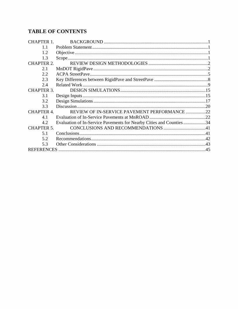
TABLE OF CONTENTS
CHAPTER 1. BACKGROUND .........................................................................................1 1.1 Problem Statement ...................................................................................................1 1.2 Objective ..................................................................................................................1 1.3 Scope ........................................................................................................................1
CHAPTER 2. REVIEW DESIGN METHODOLOGIES ...................................................2 2.1 MnDOT RigidPave ..................................................................................................2 2.2 ACPA StreetPave .....................................................................................................5 2.3 Key Differences between RigidPave and StreetPave ..............................................8 2.4 Related Work ...........................................................................................................9
CHAPTER 3. DESIGN SIMULATIONS .........................................................................15 3.1 Design Inputs .........................................................................................................15 3.2 Design Simulations ................................................................................................17 3.3 Discussion ..............................................................................................................20
CHAPTER 4. REVIEW OF IN-SERVICE PAVEMENT PERFORMANCE .................22 4.1 Evaluation of In-Service Pavements at MnROAD ................................................22 4.2 Evaluation of In-Service Pavements for Nearby Cities and Counties ...................34
CHAPTER 5. CONCLUSIONS AND RECOMMENDATIONS ....................................41 5.1 Conclusions ............................................................................................................41 5.2 Recommendations ..................................................................................................42 5.3 Other Considerations .............................................................................................43
REFERENCES ..............................................................................................................................45

LIST OF TABLES
Table 1. MnDOT RigidPave Inputs ................................................................................................ 4 Table 2. AASHTO ‘93 Inputs ......................................................................................................... 4 Table 3. Reliability Calculations for MnDOT RigidPave Using AASHTO ’93 ............................ 5 Table 4. Selected Concrete Design Parameters for Evaluation of Neighboring States to Minnesota (from ACPA)............................................................................................................... 11 Table 5. StreetPave Baseline Inputs for Sensitivity ...................................................................... 16 Table 6. StreetPave Sensitivity to Design Inputs (Resulting Change in Design Thickness Compared to Baseline of 6.6”)...................................................................................................... 16 Table 7. RigidPave Design Inputs ................................................................................................ 16 Table 8. StreetPave Design Inputs ................................................................................................ 17 Table 9. RigidPave Versus StreetPave Design Thicknesses ......................................................... 18 Table 10. StreetPave Designs for Local Roads ............................................................................. 20 Table 11. Average As-Built Thicknesses of MnROAD Cells ...................................................... 23 Table 12. Range of Composite k-Value Recommendations from StreetPave .............................. 24 Table 13. Average Composite k-Values from StreetPave Recommendations ............................. 24 Table 14. MnROAD Mainline Single Axles................................................................................. 27 Table 15. MnROAD Mainline Tandem Axles .............................................................................. 27 Table 16. MnROAD Mainline Tridem Axles ............................................................................... 27 Table 17. StreetPave Design Inputs for MnROAD Test Cells ..................................................... 28 Table 18. StreetPave Analysis Results for MnROAD Test Cells with Comparison Using RigidPave ...................................................................................................................................... 29 Table 19. Adjusted Reliability and Percent Cracking to Achieve One Year of Service Life ....... 30 Table 20. MnDOT RQI Description ............................................................................................. 30 Table 21. McLeod County, MN Design Parameters ..................................................................... 36 Table 22. Michigan DOT M-13 Design Parameters ..................................................................... 37 Table 23. Michigan DOT M-99 Design Parameters ..................................................................... 38 Table 24. StreetPave Backcalculated Design Life for City and County In-Service Pavements ... 40
1
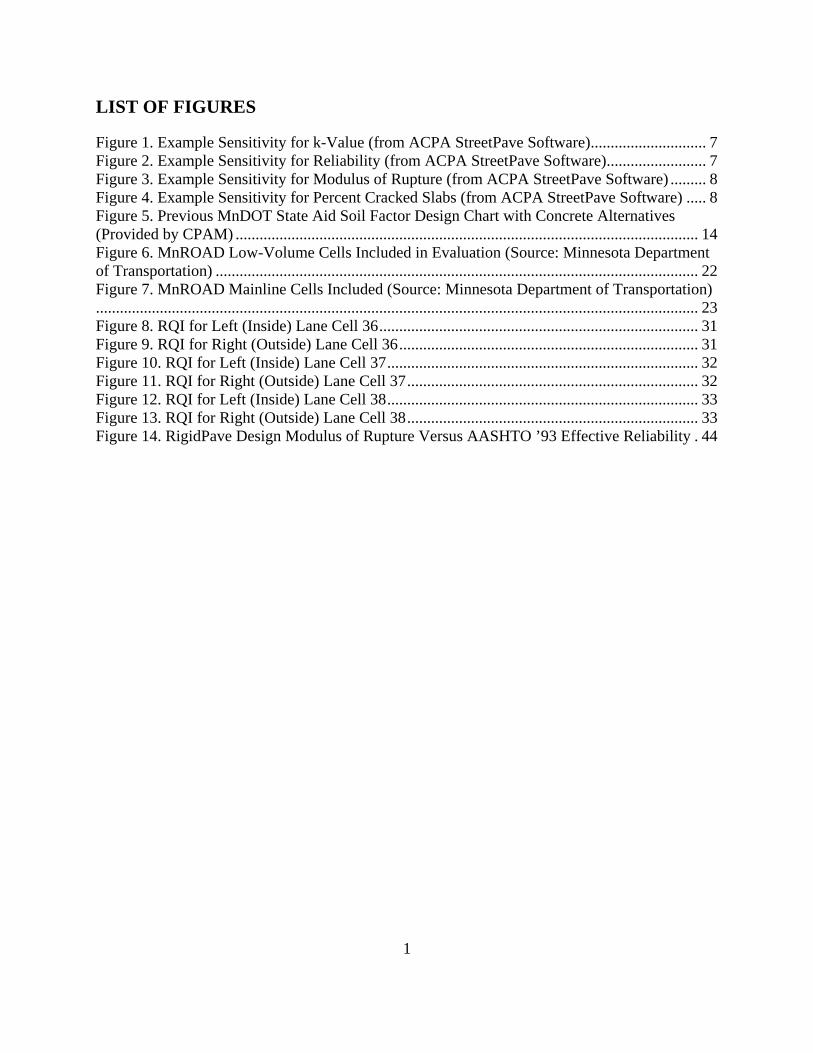
LIST OF FIGURES
Figure 1. Example Sensitivity for k-Value (from ACPA StreetPave Software) ............................. 7 Figure 2. Example Sensitivity for Reliability (from ACPA StreetPave Software) ......................... 7 Figure 3. Example Sensitivity for Modulus of Rupture (from ACPA StreetPave Software) ......... 8 Figure 4. Example Sensitivity for Percent Cracked Slabs (from ACPA StreetPave Software) ..... 8 Figure 5. Previous MnDOT State Aid Soil Factor Design Chart with Concrete Alternatives (Provided by CPAM) .................................................................................................................... 14 Figure 6. MnROAD Low-Volume Cells Included in Evaluation (Source: Minnesota Department of Transportation) ......................................................................................................................... 22 Figure 7. MnROAD Mainline Cells Included (Source: Minnesota Department of Transportation)....................................................................................................................................................... 23 Figure 8. RQI for Left (Inside) Lane Cell 36 ................................................................................ 31 Figure 9. RQI for Right (Outside) Lane Cell 36 ........................................................................... 31 Figure 10. RQI for Left (Inside) Lane Cell 37 .............................................................................. 32 Figure 11. RQI for Right (Outside) Lane Cell 37 ......................................................................... 32 Figure 12. RQI for Left (Inside) Lane Cell 38 .............................................................................. 33 Figure 13. RQI for Right (Outside) Lane Cell 38 ......................................................................... 33 Figure 14. RigidPave Design Modulus of Rupture Versus AASHTO ’93 Effective Reliability . 44

1
EXECUTIVE SUMMARY
The Minnesota Department of Transportation’s (MnDOT) concrete pavement design procedure is based on the 1981 American Association of State Highway and Transportation Officials (AASHTO) Interim Guide with a modification to adapt to local conditions. The AASHTO procedures are tied to the 1958-1960 AASHTO Road Test results, and thus, the MnDOT design procedure is entirely empirically-based. Since the time of the Road Test much more knowledge has been learned about pavement design and performance. The design method utilized in American Concrete Pavement Association’s (ACPA) StreetPave software is based on the Portland Cement Association (PCA) thickness design method. The StreetPave software incorporates results from the AASHTO Road Test, more recent information from mechanistic-empirical studies, and a newly updated fatigue model. This study compared MnDOT’s RigidPave program to ACPA’s StreetPave program. Included was a review of the input variables for each system, as well as a review of the design inputs used by surrounding DOTs. A review was conducted of known thin (six inches or less) concrete pavements in both Minnesota and neighboring states for design comparison purposes. This review included both city and county pavements, as well as eight concrete test cells at MnROAD. In general, RigidPave and StreetPave are too different in their methodologies to perform a direct comparison. There are two primary differences between the two methods: 1) traffic is handled differently – RigidPave uses ESALs and StreetPave uses load spectra; and 2) the design methodology – RigidPave is empirical while StreetPave is both mechanistic and empirical. Both are based on time-tested and proven design methodologies and provide generally similar designs when comparable conditions are considered, although they should not be expected to produce identical design thicknesses. It is essential that the designer understands the inputs, their origin, and the impact of each on the calculated design thickness. The original MnROAD low-volume concrete test cells provided the best opportunity to evaluate the StreetPave procedure. The predicted design lives of these low-volume cells appears to be in line whether evaluated using StreetPave or RigidPave. In addition, the measured ride quality index (RQI) data indicates very good performance after 14 years of service. The examples provided by cities and counties typically did not contain enough known information, and therefore, required a lot of assumptions for analysis. The assumptions were made based on best guesses from traffic maps, soil maps, etc., but any erroneous values could compound and drastically skew the results, and in most cases, were eliminated due to this factor. StreetPave is based on the time-tested and proven PCA thickness procedure with roots dating back to the 1930s. The fatigue model in StreetPave was updated in 2005 and has been referred to as “the best available fatigue model”. In addition, the Virginia Department of Transportation allows both the PCA and ACPA design methods for secondary roads. As a result of this study and the literature reviews, the authors recommend that StreetPave is added as an alternate concrete pavement thickness design procedure for city and county projects in Minnesota. The authors do not in any way endorse the equivalent asphalt design component or the life cycle cost module. This is because these were not evaluated as part of the scope of this project.

Based on performance observed at MnROAD, it is recommended that the minimum concrete pavement thickness be reduced from six inches to five inches for city and county projects. This is already allowed on a project-by-project basis but requires approval from the MnDOT pavement design engineer. Joint spacing on such projects should be in the 10- to 12-foot range. It was also determined that RigidPave has a built-in reliability of about 89%, based on the AASHTO ’93 design procedure. This is due to the fact that a factor of safety is applied to the modulus of rupture because a reliability input was not available when RigidPave was developed. An alternate approach to allowing StreetPave as a design option would be to incorporate the reliability knowledge of RigidPave learned as part of this project.

1
CHAPTER 1. BACKGROUND
1.1 Problem Statement
Concrete pavements in Minnesota have been designed for decades using the American Association of State Highway and Transportation Officials (AASHTO) ’72 design method as revised in 1981. This method used the empirical data obtained from the AASHTO Road Test in Illinois in the 1950’s. The AASHTO Road Test only lasted two years and obtained limited data. The Minnesota Department of Transportation’s (MnDOT) preferred design software, RigidPave, used for their trunk highways and by default on local roads, is based on this limited data. Since that time much more knowledge has been learned about pavement design. The design method utilized in the StreetPave software, developed by the American Concrete Pavement Association (ACPA), is based on the Portland Cement Association’s (PCA) thickness design method and recent long term pavement performance data that was included in the new AASHTO Mechanistic-Empirical design method. Allowing StreetPave as a thickness design alternative might lead to more optimized pavements, thus resulting in savings to taxpayers.
1.2 Objective
The goals of this study are to compare and document the differences between MnDOT’s RigidPave program and ACPA’s StreetPave program, highlight the differences in the thickness design methodology, and learn how to reconcile these differences. A review will also be conducted of the input variables used by surrounding DOTs using the RigidPave software or other similar methods to compare results; the ACPA’s website will be the source of DOT information (http://apps.acpa.org/apps/APDPass.aspx). The results of StreetPave will also be compared to data obtained by the MnROAD test facility to assess them relative to data for in-service concrete pavements. The ultimate goal of the project, as indirectly identified in the Local Road Research Board (LRRB) problem statement, is to make a recommendation to allow or disallow the use of StreetPave for use on City and County State Aid projects in Minnesota.
1.3 Scope
1 Compare and document the differences between MnDOT’s RigidPave program and ACPA’s StreetPave program to show the major differences in concrete pavement thickness for various designs. The differences in design methodology will also be highlighted to better understand the reasons for differences in design thickness. Finally, the results from StreetPave will be evaluated against in-service rigid pavements, such as at MnROAD or in the County system.

2
CHAPTER 2. REVIEW DESIGN METHODOLOGIES
2.1 MnDOT RigidPave
MnDOT’s RigidPave design procedure is based on the 1981 AASHTO Interim Guide with a modification to adapt to local conditions [1]. As a result of having its roots tied to the 1958-1960 AASHTO Road Test, the MnDOT procedure is entirely empirically based. Under this design method, MnDOT designs and constructs only Jointed Plain Concrete Pavement (JPCP). The design procedure has traditionally been a software-type application but has recently switched to a spreadsheet format. The following are MnDOT recommendations for designing JPCP.
2.1.1 Slab Thickness
Slab thickness is determined using the cumulative 35-year design-lane Concrete Equivalent Single Axle Loads (CESALs), which are based on the AASHTO Load Equivalency Factors (LEFs). The equation was developed from the AASHTO Road Test and solves for the cumulative number of ESALs a pavement can withstand before it falls to a given serviceability level. Historically, MnDOT has required a 7-inch minimum concrete pavement thickness for State Highways. In the new spreadsheet version of RigidPave, MnDOT requires a minimum thickness of 6-inches for State Highways. However, the MnDOT Pavement Design Engineer can approve designs less than 6-inches for City and County projects on a case-by-case basis.
Standard values used in RigidPave are:
• pt = terminal serviceability. A value of 2.5 is used for both urban and rural designs. • k-value = modulus of subgrade reaction. Correlation between plate load tests and soil
R-value tests were done as part of MnDOT Investigation 183 and the following equation is built into the RigidPave program. MnDOT does note that this relationship differs significantly from those of other agencies and that caution should be taken when evaluating different design procedures.
k = −1.17 + 63�R-value Eq. 1
• Sc = concrete modulus of rupture. MnDOT includes a safety factor of 1.33 into the design and the accepted value for RigidPave design is Sc = 500 psi.
• E = concrete modulus of elasticity. This value is rarely tested and MnDOT assumes a value of 4,200,000 psi.
• Wt = number of ESALs to reach pt. To account for harsher winter conditions and the resulting longer frozen subgrade and base periods in Minnesota than in Illinois, an adjustment factor of 0.93 is applied to the forecasted ESALs.
2.1.2 Protected Edge
The protected edge design is MnDOT’s standard. A protected edge can be a widened lane, tied-concrete shoulder, curb & gutter, or the interior lanes if more than four 12-foot lanes. MnDOT

3
uses values directly from AASHTO for J, the load transfer coefficient. For protected or widened edge, J = 2.6 (J = 3.2 for 12 foot width). It is commonly discussed that changing from J = 2.6 (widened) to J = 3.2 (standard) results in an increase in design thickness of approximately one inch. It should also be noted that a 13.5-foot widened pavement with a design thickness of 8-inches requires 1760 yd3 of concrete per mile, which is identical to what is required for a 12-foot wide, 9-inch thick pavement.
2.1.2 Base, Subbase and Subgrade
All new concrete pavement designs will include some amount of aggregate base and granular material. These layers can significantly affect pavement performance by improving and unifying support and providing subsurface drainage benefits. However, no structural value is assigned to these layers. The subgrade in RigidPave is characterized by R-value and is correlated to the k-value as shown in Equation 1. This equation is specific to MnDOT.
2.1.3 Transverse Concrete Joints
Typical JPCP designs are constructed with transverse joints sawed perpendicular to the centerline and spaced uniformly at 15 feet. For 6- to 6.5-inch concrete pavements, the typical joint spacing is 12 feet. Typically, the joints include corrosion-resistant, epoxy-coated dowel bars. The bars are generally 15 inches in length and are placed mid-depth in the pavement at a12-inch spacing.
2.1.4 Reliability
Reliability is not an input in RigidPave, but is an important factor in pavement design procedures, particularly in AASHTO ’93 and StreetPave. To truly compare MnDOT RigidPave and StreetPave, an estimate of the inherent reliability in the MnDOT design procedure is necessary. The AASHTO ’81 equation [1] is identical to the AASHTO ’93 equation [2] except for the addition of ZR (standard normal deviate z-value), SO (overall standard deviation), and CD (drainage coefficient).
In the determination of inherent reliability for RigidPave, values were needed for SO and CD. AASHTO recommends SO values between 0.30 to 0.40, so 0.35 was used to represent average conditions. A value of 1.0 was used for CD so there was no significance to this variable.
Thickness designs were then conducted at several ESAL and k-value levels. The full range of input values is shown in Table 1. A spreadsheet was created to solve the AASHTO ’93 rigid pavement design equation for the inputs shown in Table 2. The pavement thickness was set equal to the RigidPave design and values of ZR/Reliability were solved by setting the difference in calculated ESALs (W18) between each equation equal to zero.

4
Table 1. MnDOT RigidPave Inputs
Design Input Value(s) Reason For Selection
R-value 12 – 40 – 70 Typical low, medium, and high values were chosen for Minnesota’s soils.
k-value 217 – 397 – 526 These were calculated using the equation relating R-value to k-value in RigidPave.
ESALs 500,000 – 3,000,000 – 10,000,000
These were arbitrarily chosen to represent low, medium, and high ESAL values.
ESAL Adjustment Factor 0.93 RigidPave-specific input.
J 3.2 Set to evaluate a typical non-widened concrete pavement.
Pt 2.5 RigidPave-specific input. Sc (psi) 500 RigidPave-specific input.
Table 2. AASHTO ‘93 Inputs
Design Input Value(s) Reason For Selection k-value 217 – 397 – 526 Included to mimic RigidPave.
ESALs 465,000 – 2,790,000 – 9,300,000
These are the result of the ESAL values in Table 1 and the 0.93 ESAL factor.
J 3.2 Included to mimic RigidPave. Pt 2.5 Included to mimic RigidPave.
Sc (psi) 665* The 1.33 safety factor built into RigidPave was not used outside of RigidPave. See * note.
*A Factor of Safety (FOS) of 1.33 has historically been applied in the RigidPave design procedure to reduce the design modulus of rupture. Using the default value in RigidPave of 500 psi, a value of 665 psi (500*1.33) was used to evaluate other design methods [2].
The results from this analysis provided a very consistent value of effective reliability of approximately 89%. The full results are shown in Table 3.
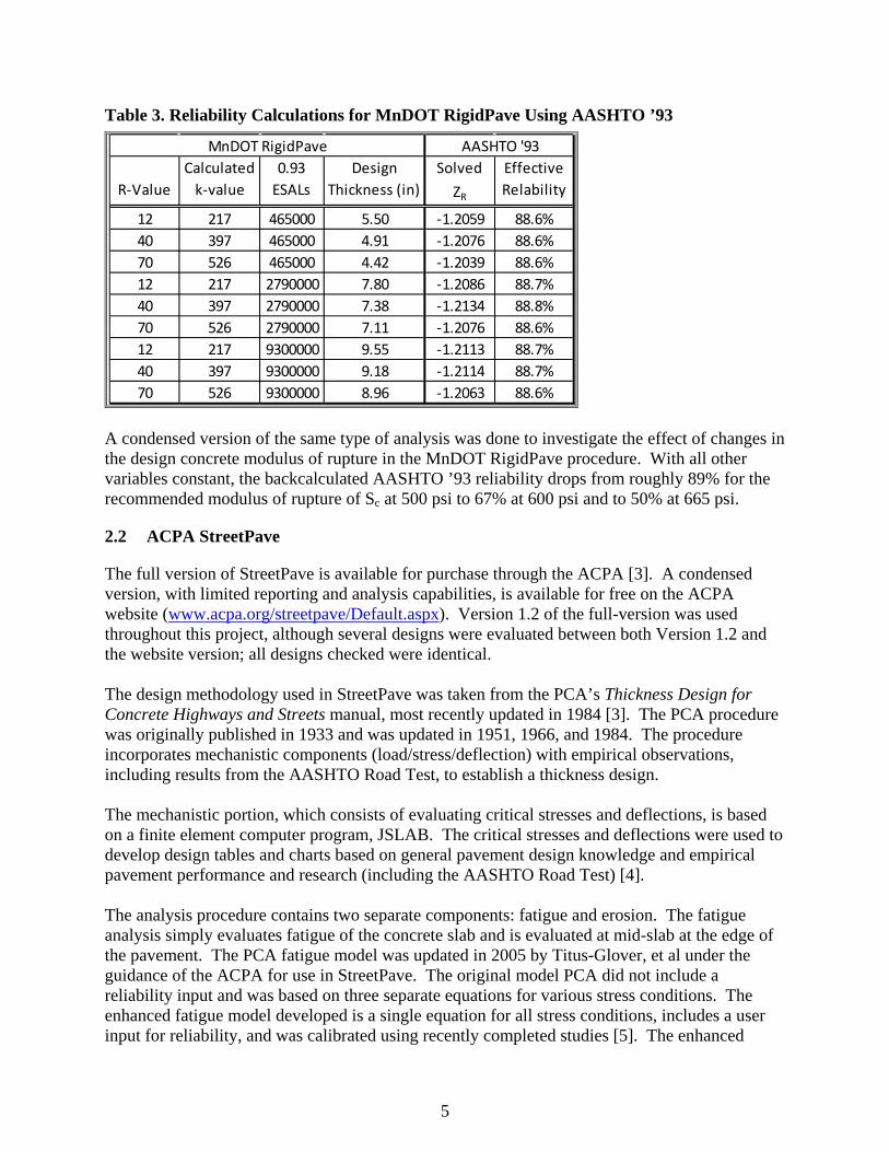
5
Table 3. Reliability Calculations for MnDOT RigidPave Using AASHTO ’93
A condensed version of the same type of analysis was done to investigate the effect of changes in the design concrete modulus of rupture in the MnDOT RigidPave procedure. With all other variables constant, the backcalculated AASHTO ’93 reliability drops from roughly 89% for the recommended modulus of rupture of Sc at 500 psi to 67% at 600 psi and to 50% at 665 psi.
2.2 ACPA StreetPave
The full version of StreetPave is available for purchase through the ACPA [3]. A condensed version, with limited reporting and analysis capabilities, is available for free on the ACPA website (www.acpa.org/streetpave/Default.aspx). Version 1.2 of the full-version was used throughout this project, although several designs were evaluated between both Version 1.2 and the website version; all designs checked were identical. The design methodology used in StreetPave was taken from the PCA’s Thickness Design for Concrete Highways and Streets manual, most recently updated in 1984 [3]. The PCA procedure was originally published in 1933 and was updated in 1951, 1966, and 1984. The procedure incorporates mechanistic components (load/stress/deflection) with empirical observations, including results from the AASHTO Road Test, to establish a thickness design. The mechanistic portion, which consists of evaluating critical stresses and deflections, is based on a finite element computer program, JSLAB. The critical stresses and deflections were used to develop design tables and charts based on general pavement design knowledge and empirical pavement performance and research (including the AASHTO Road Test) [4]. The analysis procedure contains two separate components: fatigue and erosion. The fatigue analysis simply evaluates fatigue of the concrete slab and is evaluated at mid-slab at the edge of the pavement. The PCA fatigue model was updated in 2005 by Titus-Glover, et al under the guidance of the ACPA for use in StreetPave. The original model PCA did not include a reliability input and was based on three separate equations for various stress conditions. The enhanced fatigue model developed is a single equation for all stress conditions, includes a user input for reliability, and was calibrated using recently completed studies [5]. The enhanced
R-ValueCalculated
k-value0.93
ESALsDesign
Thickness (in)Solved
ZR
Effective Relability
12 217 465000 5.50 -1.2059 88.6%40 397 465000 4.91 -1.2076 88.6%70 526 465000 4.42 -1.2039 88.6%12 217 2790000 7.80 -1.2086 88.7%40 397 2790000 7.38 -1.2134 88.8%70 526 2790000 7.11 -1.2076 88.6%12 217 9300000 9.55 -1.2113 88.7%40 397 9300000 9.18 -1.2114 88.7%70 526 9300000 8.96 -1.2063 88.6%
AASHTO '93MnDOT RigidPave

6
fatigue model was recently recommended as the fatigue model for the design procedure of pervious concrete because it was considered “the best available fatigue model” [6]. The erosion analysis evaluates the potential for a concrete pavement to fail by pumping, erosion of the foundation support, and/or joint faulting, and is based on corner deflections [4]. The primary failure observed at the AASHTO Road Test in the concrete pavements was pumping or erosion of the support layers. The PCA created the erosion model to limit the likelihood of this type of failure. The model is based on AASHTO Road Test results with additional faulting studies from several states, including Minnesota. The model evaluates the power or work done by the pavement system as a function of corner deflection, pressure at the slab-foundation interface, concrete modulus of elasticity and Poisson’s ratio, slab thickness, and modulus of subgrade reaction. Conceptually, a thinner pavement has a shorter deflection basin than a thicker pavement, and therefore, will “punch” into the subbase faster [7]. The procedure allows for single, tandem, and tridem axles with up to 10 axle weights in each group, essentially creating what is commonly referred to as “load spectra.” The cumulative damage concept, or Miner’s hypothesis, is utilized to evaluate the accumulation of damage from each of the load subgroups. The damage is evaluated as a ratio of the number of loads of a given axle to the number of allowable loads of the same combination and is considered sufficient if the cumulative damage of all loads is less than 1.0.
2.2.1 StreetPave Design Input Summary
StreetPave has many inputs required for a given design which include: • Mean Annual Air Temperature (MAAT) (this input is not used in concrete pavement
design and only affects the equivalent asphalt pavement design [8]) • Terminal Serviceability (pt) (this input is not necessary for concrete pavement design and
is only used to calculate the number of ESALs for the asphalt pavement design [8]) • Percent cracked slabs at end of service life • Design life • Reliability • Traffic category (residential, collector, minor arterial, major arterial, and user-defined) • Design lanes & directional distribution • Average Daily Truck Traffic (ADTT) or Average Daily Traffic (ADT) with % trucks • Traffic growth • Modulus of subgrade reaction, k • Average 28-day flexural strength, Mr (equal to Sc in AASHTO) • Concrete modulus of elasticity, E • Load transfer dowels • Edge support
2.2.2 Other Features
StreetPave has several additional features including: • The ability to design concrete overlays.

7
• The option to perform life cycle cost analysis (full version only). The program has built-in initial costs of equivalent pavements and predicted maintenance.
• The option to design an equivalent asphalt section (full version only). • The ability to conduct a sensitivity analysis of selected variables (full version only).
Screenshots of StreetPave sensitivity analyses are shown in Figures 1-4.
Figure 1. Example Sensitivity for k-Value (from ACPA StreetPave Software)
Figure 2. Example Sensitivity for Reliability (from ACPA StreetPave Software)

8
Figure 3. Example Sensitivity for Modulus of Rupture (from ACPA StreetPave Software)
Figure 4. Example Sensitivity for Percent Cracked Slabs (from ACPA StreetPave Software)
2.3 Key Differences between RigidPave and StreetPave
There are several key differences between the two design methodologies: • RigidPave is based entirely on empirical pavement performance observations and the
equivalent damage concept from the AASHTO Road Test. StreetPave is a mechanistic-empirical procedure based on computed stresses, strains, and deflections and empirical performance observations.
• RigidPave converts the entire traffic stream into a single traffic number, ESALs. StreetPave evaluates the traffic stream with load spectra and assesses each load and axle

9
type separately, and allows for more detailed traffic input. This detail can dramatically influence design thickness as heavy axle loads have a significant effect on loading. According to AASHTO, the relative damage caused by an axle load is proportional to the ratio of that axle load to a standard axle load expressed to the fourth power [9]. This is informally referred to by pavement engineers as the “4th Power Law”.
• StreetPave classifies roadways according to traffic category. • StreetPave incorporates the percentage of cracked slabs into design. • StreetPave allows the user to specify reliability rating. • StreetPave does allow the option to include equivalent flexible pavement design
thickness and life cycle cost analysis. However, the flexible design procedure is not MnDOT’s accepted method and was, thus, not evaluated.
2.4 Related Work
2.4.1 Review of Neighboring State DOT Concrete Pavement Design Practices
A subtask identified in the project work plan was to review concrete pavement practices for neighboring states. The work plan identified the ACPA Agency Practice Explorer as the sole source of information for other DOTs. The application is available on ACPA’s website [10]. The following states were selected for inclusion in this review:
• Illinois – info available • Iowa – info available • Michigan – info available • Nebraska – not available • North Dakota – not available • South Dakota – info available • Wisconsin – info available
A full summary is shown in Table 4.
Rigid Pavement Type Of those State agencies above that have responded to the ACPA, the majority build JPCP as Minnesota does. In South Dakota, however, about 75% of the new concrete pavements are Continuously Reinforced Concrete Pavements (CRCP). Of Michigan’s new rigid pavements, approximately 1% is Jointed Reinforced Concrete Pavement (JRCP).
JPCP Design Procedure Iowa, Michigan, and South Dakota use the AASHTO ‘86/’93 procedure, Wisconsin uses AASHTO ’72, and Illinois uses their own procedure. It appears that most states are designing highways similarly to Minnesota, with the exception of Minnesota’s 0.93 ESAL reduction factor.
JPCP Design Period Illinois, Michigan, South Dakota, and Wisconsin all use a design period of 20 years, which is considerably shorter than Minnesota’s design period of 35 years. Iowa designs for a 40-year period.

10
JPCP Minimum Thickness Similar to Minnesota, a 6-inch minimum is followed in Illinois, Michigan, and Wisconsin. However, in Iowa and South Dakota, the minimum is 8 inches.
Strength Requirement All of the selected State agencies with information available use some form of flexural strength for design. The 28-day values range from 575 to 670 psi, while Illinois requires 650 psi at 14 days. These are all substantially higher than Minnesota’s value of 500 psi. However, the AASHTO ’93 procedure used by other states allows for the incorporation of reliability, whereas the Minnesota RigidPave procedure, based on AASHTO ’81, applies a factor of safety directly to the concrete modulus of rupture value.
Shoulder Type Shoulder types vary and range from asphalt to concrete to aggregate in all states.
Widened Slab A widened slab is allowed in all surveyed states. However, the other states use a 14-foot width criterion, whereas Minnesota defines a 13-foot slab as widened/protected.

11
Table 4. Selected Concrete Design Parameters for Evaluation of Neighboring States to Minnesota (from ACPA)
Description Minnesota Illinois Iowa Michigan South
Dakota Wisconsin % New
Concrete Pavements:
JPCP
100% - 100% 99% 25% 100%
% New Concrete
Pavements: JRCP
0% - 0% 1% 0% 0%
% New Concrete
Pavements: CRCP
0% - 0% 0% 75% 0%
JPCP: Design Procedure
Modified AASHTO
81
State Procedure
AASHTO 86/93, PCA
AASHTO 86/93
AASHTO 86/93
AASHTO 72
JPCP: Design Period 35 yrs 20 yrs 40 yrs 20 yrs 20 yrs 20 yrs
JPCP: Min Thickness 6 in. 6 in. 8 in. 6 in. 8 in. 6 in.
Design Strength
Parameter
Flexural (Third Point)
Flexural (Center Point)
Flexural (Third Point)
Flexural (Center Point)
Flexural (Third Point)
Flexural (Third Point)
Thickness Design
Strength
500 psi @ 28 days
650 psi @ 14 days
575 psi @ 28 days
670 psi @ 28 days
650 psi @ 28 days
650 psi @ 26 days
Typical Shoulder on
Highways Asphalt Concrete Asphalt Concrete Asphalt Asphalt
Typical Shoulder on
Secondary Aggregate Concrete Aggregate Asphalt Aggregate Asphalt
Widened Slab Width (if
used) 13' 14' 14' 14' 14' 14'
2.4.2 Previous MnDOT State Aid Soil Factor Design Chart for Concrete Pavement
In the fall of 2005, the MnDOT Pavement Design Section, in cooperation with the Minnesota Concrete Pavement Association (CPAM), modified the long-standing MnDOT State Aid Soil Factor Pavement Design Chart. The chart had historically only provided asphalt design sections.

12
The design procedure used to develop the “catalog” of rigid pavement designs for low-volume roads was StreetPave. Of the numerous inputs in StreetPave, many were held constant for adaption to the Soil Factor design. The following summarizes what was included in the 2005 evaluation: The following inputs were considered constants for all designs:
• Mean Annual Air Temperature (MAAT) o Selected for Minnesota to be 45 degrees.
• Terminal Serviceability o The terminal serviceability was chosen to be 2.25.
• Percent cracked slabs at end of service life o 25% cracked slabs was used.
• Design life o A 20-year design life was chosen to be consistent with the asphalt design.
• Reliability o The reliability used in all designs was 75%.
• Traffic category o The traffic category used in the designs was “Collector.” A Collector is defined
as a high volume rural or secondary street or a low-volume arterial or primary highway. The typical ADTT levels of a Collector range from 40 to 1000, which fit the original design parameters well.
• Design lanes & distribution o The design was set for a 2-lane road with 50% directional distribution and 100%
design lane distribution to best simulate a 2-lane road or highway. • Traffic growth
o There was no traffic growth included in the designs. The upper portion of the chart references the traffic levels and how they should be used. For new designs a projected ADT is to be used, so traffic growth had already been considered.
• Average 28-day flexural strength o The average 28-day flexural strength used in the designs was 600 psi.
• Concrete modulus of elasticity o Young’s Modulus can be automatically calculated by StreetPave and was utilized.
For Sc =600 psi, E = 4,050,000 psi. The following inputs were varied for each design:
• ADTT o The ADTT was input for the varying levels of traffic based on the existing chart.
It was agreed that the design ADTT would be 75% of the range of each category. o The two 7-ton designs are based on an ADT of less than 400 and 400 to 1000.
MnDOT’s MinniESAL program was used to estimate the number of trucks for both 400 and 1000 ADT. MinniESAL calculated 33 and 89 trucks respectively. For the less than 400 ADT, 33 trucks were used. For the 400 to 1000 ADT, the 75% value of the range (75 trucks/day) was used.
• Load transfer dowels o Dowel bars were included for half of the designs. A 1-inch diameter bar was
assumed.

13
• Edge support o Edge support was used in half of the designs. Edge support is assumed to include:
tied curb and gutter; tied shoulder or parking lane; widened lane width of 13 feet or more.
• Modulus of subgrade reaction, k o The k-values used in the designs were supplied by MnDOT for the correlating soil
factors and were calculated based on MnDOT’s correlation between k-value and R-value.
General notes from the final document include the following:
• It was agreed that all designs would be rounded to half-inch increments as output from StreetPave. It was also agreed that the minimum undoweled pavement thickness would be 5 inches. For doweled pavements, it was agreed that the minimum thickness would be 6 inches to ensure that minimum cover for the dowels would be accomplished. It was agreed to include a doweled option on all designs with over 150 HCADT even though it added thickness. For the lower volume designs, a doweled option was only offered if the undoweled option was 5.5 inches or thicker.
• After reviewing the final designs, it was agreed that only the widened edge designs, with and without dowels, would be published. It was also agreed, after reviewing the final designs, that a note would be included requiring an additional 1 inch of thickness if a widened edge was not used.
• A note was also added to point out that a 4-inch Class 5 base was assumed for a paving platform and that local experience may dictate a thicker section. The Class 5 was not included in the design calculations and any additional Class 5 will not change the concrete thickness.
• A note referencing the Minnesota State Statute that excludes concrete pavements from seasonal load restrictions was also included.
The final version of the design chart is shown in Figure 5. Based on a memo on the MnDOT State Aid website pertaining to concrete pavement design, it is believed that the design of concrete pavements on State Aid routes reverted from the updated State Aid Soil Factor Design Chart to MnDOT RigidPave on November 15, 2010 [11].

14
Figure 5. Previous MnDOT State Aid Soil Factor Design Chart with Concrete Alternatives (Provided by CPAM)
S.F.MinimumBit. G. E.
TotalG. E.
w/odowels
w/dowels S.F.
MinimumBit. G. E.
TotalG. E.
w/odowels
w/dowels S.F.
MinimumBit. G. E.
TotalG. E.
w/odowels
w/dowels
50 3.00 7.25 5.0 N/A 50 7.00 14.00 5.0 6.0 50 8.00 20.30 5.5 6.0
75 3.00 9.38 5.0 N/A 75 7.00 17.50 5.0 6.0 75 8.00 26.40 6.0 6.0
100 3.00 11.50 5.0 N/A 100 7.00 21.00 5.0 6.0 100 8.00 32.50 6.0 6.0
110 3.00 12.40 5.0 N/A 110 7.00 22.40 5.5 6.0 110 8.00 35.00 6.0 6.0
120 3.00 13.20 5.0 N/A 120 7.00 23.80 5.5 6.0 120 8.00 37.40 6.0 6.0
130 3.00 14.00 5.0 N/A 130 7.00 25.20 5.5 6.0 130 8.00 39.80 6.0 6.0G.E. FACTOR*
2.25
S.F.MinimumBit. G. E.
TotalG. E.
w/odowels
w/dowels S.F.
MinimumBit. G. E.
TotalG. E.
w/odowels
w/dowels 2.25
50 3.00 9.00 5.0 N/A 50 7.00 16.00 5.0 6.0 2.00
75 3.00 12.00 5.0 N/A 75 7.00 20.50 5.5 6.0 1.50
100 3.00 15.00 5.0 N/A 100 7.00 25.00 5.5 6.0 1.50
110 3.00 16.20 5.0 N/A 110 7.00 26.80 5.5 6.0 1.00
120 3.00 17.40 5.0 N/A 120 7.00 28.60 5.5 6.0 0.75
130 3.00 18.60 5.5 6.0 130 7.00 30.40 6.0 6.0 0.50
SOILFACTOR ASSUMED(S.F.) % R-VALUE
S.F.MinimumBit. G. E.
TotalG. E.
w/odowels
w/dowels S.F.
MinimumBit. G. E.
TotalG. E.
w/odowels
w/dowels 50 - 75 70 - 75
50 7.00 10.25 5.0 N/A 50 8.00 18.50 5.5 6.0 50 - 75 30 - 70
75 7.00 13.90 5.0 N/A 75 8.00 23.70 5.5 6.0 50 70
100 7.00 17.50 5.0 N/A 100 8.00 29.00 5.5 6.0 100 - 130 20
110 7.00 19.00 5.0 N/A 110 8.00 31.10 6.0 6.0 130 + --
120 7.00 20.50 5.0 N/A 120 8.00 33.20 6.0 6.0 100 12
130 7.00 22.00 5.5 6.0 130 8.00 35.30 6.0 6.0 120 12
130 10NOTE: If 10 ton design is to be used, see Road Design Manual 7-3.. For full depth bituminous pavements, see Road Design Manual 7-3. * Granular Equivalent Factor per MnDOT Technical Memorandum 98-02-MRR-01 .
Concrete Design Notes: - Minimum thickness is 5"- Edge support consists of: tied curb & gutter; tied shoulder; widened lane (13' minimum). Add 1" to thickness if no edge support is used.
construction reasons. This will not affect the thickness of the concrete.- Minimum thickness for doweled concrete is 6" to ensure cover over the dowel bars. All dowels assumed to be 1" diameter and in the wheel paths, minimum.- Panel lengths should not exceed the panel width; i.e. 12' x 12', 13' x 13'. Joints in tied C & G and shoulders should match the pavement.- References to 7-Ton & 9-Ton are for comparative reasons only. MN Statute 169.87 Subdivision 2 omits portland cement concrete pavements from seasonal load restrictions.
A - 2
A - 3
A - 4
A - 5
A - 6
A - 7 - 5
A - 7 - 6
- All concrete assumed to have a minimum 4" Class 5 paving platform. Local experience may dictate a thicker section of class 5 for
Bituminous Bituminous
Plant-mixed Bit Spec 2350/2360
Plant-mixed Bit - Type 41, 61
Plant-mixed Bit - Type 31
Aggregate Base (Cl 5 & 6) 3138
Aggregate Base (Class 3 & 4) 3138
Concrete w/Edge Support
Concrete w/Edge Support
7 TON @ LESS THAN 400 ADT
PAVEMENT DESIGN USING SOIL FACTORSRequired Gravel Equivalency (G.E.) and concrete thickness for various Soil Factors (S.F.)
For new construction or reconstruction use projected ADT. For resurfacing or reconditioning use present ADT.All units of G.E. and concrete are in inches.
Bituminous
Concrete w/ Edge Support
9 TON @ 300-600 HCADT
9 TON @150-300 HCADT 9 TON @ MORE THAN 1100 HCADTConcrete w/
Edge Support BituminousBituminous
TYPE OF MATERIAL
9 TON @ LESS THAN 150 HCADT 9 TON @ 600 - 1100 HCADT
Concrete w/Edge Support
Concrete w/Edge SupportBituminous
BituminousConcrete w/
Edge Support
7 TON @ 400 - 1000 ADT
A - 1
Select Granular Spec 3149.2B
Cold In-Place Rec./ Rubblized PCC
Bit. Pavement Reclamation
SOIL CLASSAASHTO

15
CHAPTER 3. DESIGN SIMULATIONS
The current available version of the StreetPave software is 1.3. It was determined on November 30th, 2011, after the initial comparisons were complete, that the current version of the software had not been used for the design runs. According to ACPA’s website, the changes from Version 1.2 to 1.3 should have no impact on the project. The following changes identified by ACPA were taken from their website:
1. On the asphalt design type drop-down, selection options were changed to display granular base thicknesses in metric units, when the user is in metric mode.
2. Changed asphalt granular base images to depict metric units when user is in metric mode. 3. Fixed bug with aggregate base cost calculation that occurs when the user is in metric
mode or switches between English and metric units and does not select/change the aggregate base unit drop-down. Specifically, under this scenario, when running a life cycle cost report, the aggregate base cost will report an incorrect value if the user does not specifically select an option from the aggregate base unit drop-down for both concrete and asphalt.
Due to minimal changes and to maintain consistency throughout the project, StreetPave Version 1.2 was used for all design runs.
3.1 Design Inputs
Prior to conducting design simulations in RigidPave and StreetPave, a side-by-side comparison was performed of the inputs required for each system. One major difference is how traffic is incorporated into the design procedure. RigidPave uses CESALs while StreetPave uses load spectra. To equalize the two procedures in terms of traffic, an attempt was made to make an apples-to-apples comparison by choosing StreetPave inputs that mimic ESALs. This was done by using the user-defined load distribution in StreetPave and including only 1000 18-kip single axles. This results in one ESAL per truck, therefore making the total number of trucks equal to the design life ESALs. To gain a general feeling and understanding of the StreetPave software, a simple sensitivity analysis was done prior to running design simulations. The baseline inputs, chosen as arbitrary median values, are shown in Table 5. In the analysis, only one value was changed to determine its effect on design thickness. The baseline design produces a design thickness of 6.6 inches; the relative difference in thickness between the baseline and any given sensitivity evaluation is shown in Table 6.

16
Table 5. StreetPave Baseline Inputs for Sensitivity
Reliability 85% ESALs 3,000,000 k-value 300 Sc (psi) 600 Pt 2.25 Cracked Slabs 15%
Table 6. StreetPave Sensitivity to Design Inputs (Resulting Change in Design Thickness Compared to Baseline of 6.6”)
Reliability produced the greatest impact on the calculated thickness and drastically increases between a reliability of 95% and 99%. The subgrade k-value and modulus of rupture are both sensitive inputs, whereas the percentage of cracked slabs and ESALs are only moderately sensitive inputs. As suspected, the terminal serviceability had no effect on the calculated thickness. The final inputs used in the RigidPave and StreetPave design simulations are shown in Tables 7 and 8. Table 7. RigidPave Design Inputs
Design Life 35 years MnDOT’s typical design life CESALs 500,000 – 3,000,000 – 10,000,000 Low, medium, high traffic R-value 12 – 40 – 70 Low, medium, high support J-value 2.6 – 3.2 Standard or widened slab Sc (psi) 500 MnDOT’s default value E (psi) 4,200,000 MnDOT’s default value
50% 75% 85% 90% 95% 99% 0.5 3 10 100 300 500 500 600 700 2.0 2.25 2.5 5% 15% 25%Reliability -0.32 -0.24 0.00 0.19 0.53 1.99
ESALs -0.27 0.00 0.47k-value 1.00 0.00 -0.38Sc (psi) 0.73 0.00 -0.48
Pt 0.00 0.00 0.00Cracked Slabs 0.53 0.00 -0.24
Reliability ESALs (Million) k-value Sc (psi) Pt Cracked Slabs

17
Table 8. StreetPave Design Inputs
Design Life 35 years MnDOT’s typical design life
Pt 2.5 Value built into RigidPave (although not incorporated into concrete design in StreetPave)
Percent Cracks 15% StreetPave default value
Reliability 89% Match RigidPave effective reliability
Traffic Category User Defined 18-kip single axles – mimic ESALs
Truck Growth 0% per year Growth accounted for in ESALs Number of Lanes 2 Directional Distribution 50%
Sc (psi) 665 RigidPave design value * 1.33 FOS
E (psi) 4,200,000 MnDOT’s default value
3.2 Design Simulations
3.2.1 RigidPave Versus StreetPave
Once the design simulation inputs were determined, a design matrix was developed that considered various traffic loading conditions (using equivalent ESALs in StreetPave), the presence or absence of edge support and various soil characteristics. The following were the traffic loading values evaluated:
• 500,000 ESALs • 3,000,000 ESALs • 10,000,000 ESALs
Edge support, J-value in AASHTO and MnDOT design, that were studied included:
• J is 2.6 (edge support present) • J is 3.2 (no edge support)
Three values of subgrade support were evaluated. A range of R-values were arbitrarily chosen and the corresponding k-value from Equation 1 was used in both StreetPave and RigidPave. The values were as follows:
• R-value of 12 (k-value = 217) • R-value of 40 (k-value = 397) • R-value of 70 (k-value = 526)
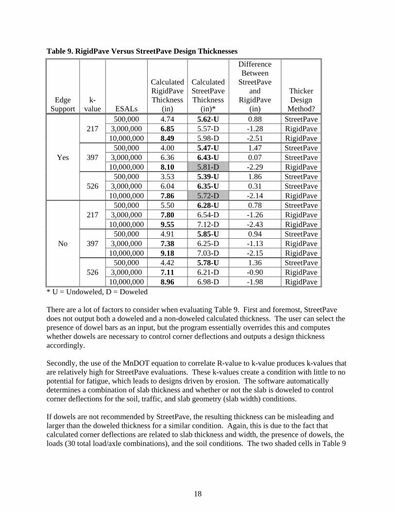
Table 9 below presents the design thickness in each system using the various inputs.
18
Table 9. RigidPave Versus StreetPave Design Thicknesses
Edge Support
k-value ESALs
Calculated RigidPave Thickness
(in)
Calculated StreetPave Thickness
(in)*
Difference Between
StreetPave and
RigidPave (in)
Thicker Design
Method?
Yes
217 500,000 4.74 5.62-U 0.88 StreetPave
3,000,000 6.85 5.57-D -1.28 RigidPave 10,000,000 8.49 5.98-D -2.51 RigidPave
397 500,000 4.00 5.47-U 1.47 StreetPave
3,000,000 6.36 6.43-U 0.07 StreetPave 10,000,000 8.10 5.81-D -2.29 RigidPave
526 500,000 3.53 5.39-U 1.86 StreetPave
3,000,000 6.04 6.35-U 0.31 StreetPave 10,000,000 7.86 5.72-D -2.14 RigidPave
No
217 500,000 5.50 6.28-U 0.78 StreetPave
3,000,000 7.80 6.54-D -1.26 RigidPave 10,000,000 9.55 7.12-D -2.43 RigidPave
397 500,000 4.91 5.85-U 0.94 StreetPave
3,000,000 7.38 6.25-D -1.13 RigidPave 10,000,000 9.18 7.03-D -2.15 RigidPave
526 500,000 4.42 5.78-U 1.36 StreetPave
3,000,000 7.11 6.21-D -0.90 RigidPave 10,000,000 8.96 6.98-D -1.98 RigidPave
* U = Undoweled, D = Doweled There are a lot of factors to consider when evaluating Table 9. First and foremost, StreetPave does not output both a doweled and a non-doweled calculated thickness. The user can select the presence of dowel bars as an input, but the program essentially overrides this and computes whether dowels are necessary to control corner deflections and outputs a design thickness accordingly. Secondly, the use of the MnDOT equation to correlate R-value to k-value produces k-values that are relatively high for StreetPave evaluations. These k-values create a condition with little to no potential for fatigue, which leads to designs driven by erosion. The software automatically determines a combination of slab thickness and whether or not the slab is doweled to control corner deflections for the soil, traffic, and slab geometry (slab width) conditions. If dowels are not recommended by StreetPave, the resulting thickness can be misleading and larger than the doweled thickness for a similar condition. Again, this is due to the fact that calculated corner deflections are related to slab thickness and width, the presence of dowels, the loads (30 total load/axle combinations), and the soil conditions. The two shaded cells in Table 9

19
illustrate two instances of this phenomenon and occurred with k-values equal to 397 and 526 with edge support conditions. Correspondence with the ACPA during this project indicates that a new release of StreetPave will provide both doweled and undoweled design thicknesses, which will help make comparisons like those shown in Table 9 more realistic (i.e., only compare doweled to doweled designs).
3.2.2 Typical StreetPave Low-Volume Design
To determine a recommended set of StreetPave inputs for low-volume road designs, generic design simulations were conducted using typical values for low-volume road applications. All four of the default traffic distributions available in StreetPave were evaluated, which include “Residential”, “Collector”, “Minor Arterial”, and “Major Arterial”. Four arbitrary values of ADTT were identified for each traffic category to mimic expected traffic levels for each traffic category. Single values were identified for reliability (75%) and design life (20 years). These options established the design thicknesses shown in Table 10.

20
Table 10. StreetPave Designs for Local Roads
Edge Support
k-value
StreetPave Traffic Category
Assumed ADTT
Calculated Design
Thickness (in)
Yes
217
Residential 50 4.5 Collector 450 5.3
Minor Arterial 850 6.2 Major Arterial 1250 6.6
397
Residential 50 4.1 Collector 450 5.0
Minor Arterial 850 5.9 Major Arterial 1250 6.5
526
Residential 50 3.9 Collector 450 4.9
Minor Arterial 850 5.8 Major Arterial 1250 6.3
No
217
Residential 50 5.3 Collector 450 6.2
Minor Arterial 850 7.1 Major Arterial 1250 7.6
397
Residential 50 4.9 Collector 450 5.7
Minor Arterial 850 6.5 Major Arterial 1250 7.1
526
Residential 50 4.7 Collector 450 5.5
Minor Arterial 850 6.3 Major Arterial 1250 6.8 Range in Calculated Thickness 3.9 -7.6
3.3 Discussion
In all design comparisons at the low ESAL level, StreetPave produced thicker design sections than did RigidPave. This is likely due to two reasons:
1. The addition of dowel bars and/or increase in slab thickness (aggregate interlock) in StreetPave to achieve minimum criteria. In all cases, the low-ESAL designs in StreetPave were driven by the erosion analysis (corner deflection/pumping/faulting) and not fatigue (traditional load-related cracking).
2. RigidPave calculations are based on AASHTO empirical observations in which all
concrete pavements were doweled. Unlike the StreetPave designs, the thin RigidPave

21
designs were not increased and the output thickness is the calculated thickness. However, MnDOT would require approval by the Pavement Design Engineer for pavements less than the 6-inch minimum, which would alter Table 9 to show thicker design sections for all low ESAL cases except for one (500,000 ESALs, k=217, and J=3.2).
In all design comparisons at the high ESAL level, StreetPave produced thinner designs than RigidPave. This is likely due to the forced simulation of ESALs (use of 18-kip single axles only) in the StreetPave designs. This approach clearly did not capture the impact of heavier axle loads and the non-linear relationship between axle load and induced damage. Including heavier axle loads would have had a definite impact on the calculated thicknesses in StreetPave. In general, the two design methods are different in their methodologies and cannot possibly be compared using a satisfactory “apples-to-apples” approach. Both are based on proven design methodologies and can be used for most situations. It is essential that the designer understands the inputs, the origin of those inputs, and the impact of each input on the calculated design thickness.

22
CHAPTER 4. REVIEW OF IN-SERVICE PAVEMENT PERFORMANCE
A subtask for this project was to evaluate in-service thin concrete pavements and backcalculate the projected service life using StreetPave. “Thin” concrete pavements were considered anything less than seven inches.
4.1 Evaluation of In-Service Pavements at MnROAD
The thin concrete pavements at MnROAD included four (4) test cells on the low-volume loop and four (4) test cells on the mainline. The low-volume cells that were evaluated were Cells 36, 37, and 38, built in 1993, and Cell 32, which was built in 2000. Mainline cells included in the evaluation are 113, 213, 313 and 413 and were built in 2008.
4.1.1 Pavement Materials
The construction of each test cell that was evaluated is shown in Figures 6 and 7.
Figure 6. MnROAD Low-Volume Cells Included in Evaluation (Source: Minnesota Department of Transportation)

23
Figure 7. MnROAD Mainline Cells Included (Source: Minnesota Department of Transportation) The actual constructed thickness of each test cell varies from the design values shown in Figures 6 and 7. Table 11 provides the average as-built thicknesses of the MnROAD test cells evaluated for this project. Table 11. Average As-Built Thicknesses of MnROAD Cells
Test Cell Location Cell
Design Thickness
(in)
As-built Thickness
(in) [reference]
Low-volume 36 6 6.53 [2]
Low-volume 37 6 6.85 [2]
Low-volume 38 6 6.57 [2]
Low-volume 32 5 5.41 [12]
Mainline 113 5 5.63 [13] Mainline 213 5.5 5.96 [13] Mainline 313 6 6.22 [13] Mainline 413 6.5 6.43 [13]

24
It should also be noted that although the mainline cells shown in Table 11 were constructed in October of 2008, they were not subjected to live traffic until February of 2009 [14]. Given that MnDOT does not recommend using their R-value/k-value relationship in design procedures outside of RigidPave, a relationship was developed using recommendations from StreetPave. The values creating a composite k-value based on unbound compacted granular subbase materials are shown in Table 12. To minimize interpolation, a simple regression was developed based on average values of those provided in Table 12. The values used to develop the regression are shown in Table 13. Table 12. Range of Composite k-Value Recommendations from StreetPave
Soil k-value
Thickness of Unbound Granular Subbase 4” 6” 9” 12”
100 106 128 116 152 132 187 149 223 150 152 183 163 212 181 256 201 300 200 200 235 206 269 226 319 248 370
Table 13. Average Composite k-Values from StreetPave Recommendations
Soil k-value
Thickness of Unbound Granular Subbase 4” 6” 9” 12”
100 117 134 160 186 150 168 188 219 251 200 218 238 273 309
A simple, two-variable linear regression was performed using soil k-value and subbase thickness as the independent variables and composite k-value as the dependent variable. The results of the regression are as follows: average composite k-value = 1.1 × k-value + 10.2 × subbase thickness - 39.0 Eq. 2 The R2 value of 0.995 indicates a nearly perfect fit. Reasonable extrapolation outside the ranges shown for soil k-value and subbase thickness in Table 13 will be okay. The only exception is for subbase thicknesses less than 4-inches where the natural soil k-value should be used instead.
4.1.2 Traffic Loading
Low-Volume Test Sections For the low-volume MnROAD cells, the traffic loading is provided by a single semi-truck that is operated by MnDOT staff. A typical day of operation results in 80 laps around the low-volume loop. Prior to 2007, there were two load configurations: the legal load, nominally 80,000 lbs gross, operated four days per week on the inside 80-kip lane of the loop road and the heavy-load, nominally 102,000 lbs gross, operated one day per week in the outside 102-kip lane [15]. Since 2007, the low-volume road test cells are loaded five days per week by the 80-kip vehicle on the inside lane; the outside lane receives no traffic loading [16].

25
StreetPave cannot model loading on only a select number of days a week, so an equivalent number of loads per day were necessary. For the two configurations, the following were used in StreetPave:
• 80-kip: 80 trucks/day * 4 days/week / (7 days/week) = 46 trucks/day • 102-kip: 80 trucks/day * 1 day/week / (7 days/week) = 11 trucks/day
In reality, the time of day that loading occurs does affect concrete pavement response to load. However, StreetPave does not incorporate any temperature effect on the concrete pavement, and thus, this assumption does not affect the predicted performance. It should be noted that temperature effects on concrete pavement are not directly accounted for in RigidPave either. There are two different semi-trucks used to pull the trailer, resulting in slightly different axle load distributions. In addition, the loads have slightly changed over time, so the average axle loads by axle type provided in the reference [15] were entered into StreetPave as the loads for the low-volume design runs.
• 80-kip: 80 trucks/day*4 day/week/(7 days/week) = 46 trucks/day o Single (steer) axle: 11.75 kips o Tandem (drive) axles: 33.5 kips (combined) o Tandem (trailer) axles: 34.1 kips (combined)
• 102-kip: 80 trucks/day * 1 day/week / (7 days/week) = 11 trucks/day o Single (steer) axle: 13 kips o Tandem (drive) axles: 44 kips (combined) o Tandem (trailer) axles: 46 kips (combined)
Mainline Test Sections The MnROAD mainline test cells are subjected to live westbound I-94 traffic. MnDOT has had three different Weigh-in-Motion (WIM) systems over the years. These systems provide the highest level of traffic data including traffic volume, lane distribution, vehicle classification, and axle distribution. Much work has been done regarding MnROAD traffic data, but a single source was used to generate the StreetPave inputs for the sake of consistency [17]. Basic StreetPave design inputs for the mainline cells were as follows:
• 4 lanes with an assumed 50/50 directional distribution • 79% design lane distribution • 12.1% trucks in the traffic stream • 5.4% traffic growth
The current traffic volume for MnROAD was obtained from the MnDOT Office of Transportation and Data Analysis. For 2008 (construction year of cells 113, 213, 313, and 413), MnROAD had a two-way daily volume of 61,000. In the research done by Oman [17], the resulting MnROAD mainline traffic data was prepared for input in the Mechanistic-Empirical Pavement Design Guide (MEPDG). In addition to the values already identified in this section, Oman developed the following values:

26
• Day of Week (DOW) distributions by vehicle classification by month • Overall Heavy Commercial (HC) breakdown by vehicle classification • Overall Time of Day (TOD) distributions • Monthly Distribution Factors (MDF) by vehicle classification • Axle Groups Per Vehicle (AGPV) (single, tandem, tridem, quad) by vehicle classification • Axle Load Factor (ALF) distributions by vehicle classification by month
StreetPave only accepts the total number of expected axles for all vehicles and not by classification. In addition, StreetPave allows for only ten load levels for single, tandem, and tridem axles, whereas the ALFs generated for the MEPDG contain 39 load levels for singles and tandems and 31 load levels for tridem and quad axles. Needless to say, a fair amount of data reduction was required to convert the MEPDG traffic input format into the StreetPave input format. The following illustrates the general approach to convert the MEPDG traffic data into the StreetPave format. The spreadsheet with all summary data and calculations will be made available to MnDOT as part of this project.
• DOW, TOD, and MDF are not included in StreetPave and are not necessary for conversion into StreetPave’s format and were ignored.
• The number of quad axles in the MEPDG format was extremely low; for this reason, and due to limitations of the StreetPave software (accepts only single, tandem, and tridem axles), they were ignored in this analysis.
• To match StreetPave’s format (axles per 1,000 trucks), a fictitious truck volume of 1,000 was used to generate the load spectra inputs.
• The HC by vehicle classification was multiplied by 1,000 to get a volume for each vehicle classification.
• The volume for each vehicle classification was multiplied by the AGPV for each axle to obtain the total number of expected axles for each vehicle type.
• ALF by month is not significant for StreetPave; overall averages by vehicle classification were calculated for each of the 39 axle loads by axle type.
• For each axle type, the total number of axle loads at each load level were multiplied by the average ALF for each vehicle type for the same load level. These were totaled across all vehicle types to establish the total number of expected axle loads at each load levels for single, tandem, and tridem axles.
• The number of different loads levels in the MEPDG needed to be reduced to 10 levels for StreetPave. The load levels in StreetPave for the Major Arterial traffic category were used and are shown in Tables 14A-C.
• Because there were intermediate values to consider in the MEPDG axle loads (i.e., single axles @ 15, 16, 17, etc), 50% of the number of axles below the StreetPave value and 50% of the values above the StreetPave value were also assumed to be included in the distribution for the StreetPave load value. For example, the calculated number of single axles at 15-, 16-, and 17-kip load levels in the MEPDG were 33.14, 25.76, and 29.66, respectively. The amount of 16-kip singles in the final StreetPave distribution was 33.14*.5+25.76+29.66*.5 = 57.2 16-kip axles per 1000 trucks.

27
The final reduced output is shown in Tables 14A – C. These were entered into StreetPave as a “user-defined” traffic category. Table 14. MnROAD Mainline Single Axles
Kips Axles / 1000 Trucks 16 57.2 18 50.7 20 29.5 22 8.14 24 1.60 26 0.296 28 0.111 30 0.050 32 0.004 34 0.001
Table 15. MnROAD Mainline Tandem Axles
Kips Axles / 1000 Trucks 24 174.8 28 179.1 32 218.1 36 159.3 40 38.0 44 4.14 48 0.528 52 0.085 56 0.022 60 0.006
Table 16. MnROAD Mainline Tridem Axles
Kips Axles / 1000 Trucks 24 2.08 30 3.56 36 8.66 42 9.20 48 3.48 54 0.985 60 0.331 66 0.115 72 0.028 78 0.008

28
4.1.3 Design Inputs
Young’s Modulus (E) was set to 4,200,000 psi for all design runs as it is very seldom tested and has little effect on pavement design [2]. The modulus of rupture (Mr) was provided by MnDOT for some cells but not for others. In the case where no modulus of rupture was available, a value of 665 psi was used (500 psi * 1.33 factor of safety). The final inputs for both the mainline and low-volume test cells are as shown Table 23: Table 17. StreetPave Design Inputs for MnROAD Test Cells
36 37 38 32 113 213 313 413 Percent Cracking 15% 15% 15% 15% 5% 5% 5% 5% Reliability 75% 75% 75% 75% 89% 89% 89% 89%
Traffic Category 80k, 102k
80k, 102k
80k, 102k
80k, 102k User User User User
Truck Growth 0% 0% 0% 0% 5.4% 5.4% 5.4% 5.4% Number of Lanes 2 2 2 2 4 4 4 4 Directional Distribution 100% 100% 100% 100% 79% 79% 79% 79% Assumed R-value 70 70 12 12 12 12 12 12 Soil k-value* 220 220 75 75 75 75 75 75 Composite k-value** 254 254 95 105 146 146 135 130 Mr (psi)*** 685 736 751 714* 665 665 665 665 Dowel Bars Yes No Yes No Yes Yes Yes Yes Average As-Built Thickness (in) 6.53 6.85 6.57 5.41 5.63 5.96 6.22 6.43
* Assumed values derived from StreetPave help file. ** Values calculated from Equation 2 and subbase thicknesses from Figures 6 and 7. *** Mr data was provided by MnDOT. Cell 32, Mr was provided by Burnham [14].
4.1.4 Analysis Results
The results of the MnROAD design simulations are shown in Table 24.

29
Table 18. StreetPave Analysis Results for MnROAD Test Cells with Comparison Using RigidPave
Cell
Projected Years Until Failure in StreetPave
Controlling Failure Mode in StreetPave
Backcalculated RigidPave
Allowable ESALs (based on cell
values in Tables 11 and 15)
Approximate Projected Number
of Years Until Failure in
RigidPave* 36, 80-kip 101 Erosion 2,034,000 101 36, 102-kip 76 Erosion 37, 80-kip 37 Erosion 2,516,000 125 37, 102-kip 30 Erosion 38, 80-kip 59 Erosion 1,200,000 60 38, 102-kip 46 Fatigue 32, 80-kip 3 Erosion 460,000 23 32, 102-kip < 1 Fatigue
113 < 1 Fatigue 557,000 < 1 213 < 1 Fatigue 735,000 < 1 313 < 1 Fatigue 903,000 < 1 413 < 1 Fatigue 1,070000 1
* Based on allowable ESALs as determined by RigidPave and approximate ESALs per year for the low-volume and mainline test cells provided by MnDOT [18]. From this reference, MnDOT indicates that the low-volume concrete cells receive approximately 20,000 ESALs/year; this is independent of the lane (80-kip or 102-kip). The mainline concrete cells receive approximately 1,000,000 ESALs/year. Although some scatter is evident, the predicted number of years until failure using StreetPave or RigidPave for the MnROAD Cells 36 and 38 are reasonably close. The predictions for Cells 37 and 32 are significantly different, with RigidPave predicting far longer service lives. These two cells, though, are the only un-doweled sections evaluated, and neither the RigidPave software nor the MnDOT Pavement Manual provides guidance for designing without dowel bars. In fact, the AASHTO ’93 Guide recommends that a designer considering using un-doweled joints should develop an appropriate J-value or check their design with another procedure, such as the PCA [9]. The predictions for the mainline cells (113-413) are essentially equal between the two methods. It should be noted that likely no concrete pavement design procedure would predict more than over two years of service life for the four thin mainline sections, due to the extremely heavy interstate traffic loading conditions. The StreetPave analysis could be improved with known concrete modulus of rupture values as opposed to assumed average values. This is because the fatigue criteria in StreetPave are directly related to stress ratio (applied stress/allowable stress). The four mainline cells and one low-volume cell that are not projected to provide at least one year of service were evaluated in further detail. To achieve at least one year of service, the

30
reliability and/or percent cracking values were varied in StreetPave to achieve one year of service. Table 23 shows the values necessary to achieve one year of predicted service life. Table 19. Adjusted Reliability and Percent Cracking to Achieve One Year of Service Life
Cell Reliability Percent
Cracking 32, 102-
kip 62% 15%
113 39% 50% 213 50% 34% 313 50% 23% 413 50% 16%
4.1.5 Pavement Performance Observations
Performance data is routinely collected at MnROAD. MnDOT currently utilizes three different rating types to quantify the condition of the pavement and project future conditions. The three metrics include Ride Quality Index (RQI) or pavement roughness, which is measured on a 0.0 to 5.0 scale; Surface Rating (SR), measured on a 0.0 to 4.0 scale; and the Pavement Quality Index (PQI), ranging from 0.0 to 4.5 [19]. The PQI is essentially a composite of both RQI and SR. MnDOT’s descriptive ratings and the corresponding ranges of RQI values is shown in Table 24. Table 20. MnDOT RQI Description
RQI Range Descriptive Rating 4.1 - 5.0 Very Good 3.1 - 4.0 Good 2.1 - 3.0 Fair 1.1 - 2.0 Poor 0.0 - 1.0 Very Poor
MnROAD Low-Volume Cells Pavement performance data was provided by MnDOT for the three original low-volume cells included (36, 37, and 38). Historical RQI values are provided in the following figures.

31
Figure 8. RQI for Left (Inside) Lane Cell 36
Figure 9. RQI for Right (Outside) Lane Cell 36
0.00
0.50
1.00
1.50
2.00
2.50
3.00
3.50
4.00
4.50
5.00Ri
de Q
ualit
y In
dex
(RQ
I)RQI for Left Lane Cell #36
LWP
RWP
0.00
0.50
1.00
1.50
2.00
2.50
3.00
3.50
4.00
4.50
5.00
Ride
Qua
lity
Inde
x (R
QI)
RQI for Right Lane Cell #36
LWP
RWP

32
Figure 10. RQI for Left (Inside) Lane Cell 37
Figure 11. RQI for Right (Outside) Lane Cell 37
0.00
0.50
1.00
1.50
2.00
2.50
3.00
3.50
4.00
4.50
5.00Ri
de Q
ualit
y In
dex
(RQ
I)RQI for Left Lane Cell #37
LWP
RWP
0.00
0.50
1.00
1.50
2.00
2.50
3.00
3.50
4.00
4.50
5.00
Ride
Qua
lity
Inde
x (R
QI)
RQI for Right Lane Cell #37
LWP
RWP

33
Figure 12. RQI for Left (Inside) Lane Cell 38
Figure 13. RQI for Right (Outside) Lane Cell 38
0.00
0.50
1.00
1.50
2.00
2.50
3.00
3.50
4.00
4.50
5.00Ri
de Q
ualit
y In
dex
(RQ
I)RQI for Left Lane Cell #38
LWP
RWP
0.00
0.50
1.00
1.50
2.00
2.50
3.00
3.50
4.00
4.50
5.00
Ride
Qua
lity
Inde
x (R
QI)
RQI for Right Lane Cell #38
LWP
RWP
There are certainly inconsistencies over time in the RQI provided by MnDOT as the measured International Roughness Index (IRI) is affected by the pavement’s response to the temperature at

34
the time of measurement. That said, general trends of performance data are easily identifiable from the provided figures. The RQI data does not extend to the current date, but regardless, all three low-volume cells were in “good” condition (RQI levels between 3 and 4) after nearly 14 years of service (where the available RQI data terminates). In terms of ride quality, this level of performance at least does not contradict the performance life ranges predicted by StreetPave. The actual performance of the low-volume cells will likely be between the 30 to 101 years predicted by StreetPave, but without projections from a pavement management system, it is difficult to relate actual performance to predicted performance at these extreme timeframes. RigidPave predicts a reasonably similar number of years of service for the low-volume test cells. As a point of reference, the original low-volume concrete cells were designed in 1992 using RigidPave for a three year design life [2]. The calculated design thicknesses of slightly over four inches were rounded up to the MnDOT minimum thickness of six inches [20].
MnROAD Mainline Cells Basic performance data was provided by MnDOT for the mainline cells [14]. The first observed slab cracking occurred on cells 113 and 213 in September of 2010, which was after approximately a year and a half of service. It is Tom Burnham’s opinion that sensor leads and supports within the pavement created a weakened plane that led to accelerated cracking in these areas. However, some of the cracking present in cells 113 and 213 is also due to fatigue as the cracks occurred in non-instrumented panels. Full-depth repairs were conducted on the panels in August of 2011, but many panels continue to perform well. According to the StreetPave analysis for typical interstate inputs, the test sections should have only lasted a few days or weeks before failing in fatigue. Clearly the pavement has performed far superior to what is predicted by StreetPave and further evaluation into materials properties would be necessary to fully understand the performance observed.
4.2 Evaluation of In-Service Pavements for Nearby Cities and Counties
At the Task 2B Technical Advisory Panel meeting, several cities, counties, and DOTs were identified by the TAP to include in a general survey. Email and phone surveys were conducted with several cities and counties in Minnesota and surrounding states, as well as surrounding DOTs. The response rate was not 100%, but the participation provided a range of potential pavements to evaluate. Each agency was asked to provide design and construction details for any thin (6 inches or less) in-service pavements. The following agencies were contacted and the responses are summarized below.
• McLeod County, MN – pavement section provided and most supporting information • Michigan DOT – pavement sections provided and some supporting information • City of Cherokee, IA – pavement section provided but limited supporting information • City of Austin, MN – pavement sections provided but limited supporting information

35
City of St. Anthony, MN – pavement section provided but limited supporting information City of Kaukauna, WI – pavement section provided but limited supporting information City of Johnston, IA – indicated no thin concrete pavements exist City of East Grand Forks, MN – indicated no thin concrete pavements exist City of Fridley, MN – indicated no thin concrete pavements exist City of Minneapolis, MN – no data provided City of Bettendorf, IA – no data provided
4.2.1 Design Inputs
McLeod County, Minnesota – CSAH 2
One thin concrete pavement exists in McLeod County on CSAH 2. The road was constructed to a 6-inch design thickness. However, it should be noted that the southern 4000 feet was constructed to seven inches because the poor subgrade conditions got progressively worse from heavy construction traffic. The following design parameters were provided and/or assumed for modeling of this pavement section:

36
Table 21. McLeod County, MN Design Parameters
Agency McLeod County, MN Segment CSAH 2 Year Built 2006
Pavement Design Cross Section 6” PCC 3” reclaimed bituminous and agg base 2” class 5
Reliability 85% (assumed value for Collector) % Cracked Slabs 15% (assumed value for Collector)
R-value 6 to 12 (assumed for clays, however, County borings indicated very wet and weak soils in areas)
k-value 50 (R-value = 6) to 75 (R-value = 12) (assumed based on “low” support in StreetPave help file for recommended k-values)
Composite k-value* 67 (R-value = 6) to 95 (R-value = 12)
Material Properties • Mr = 665 psi (calculated from project beam
breaks) • E = 4,200,000 (assumed)
Dowels Yes Edge Support Yes, widened slab
Traffic Data
• Collector (assumed) • ADT = 1,350 (provided by County) • % Trucks = 8.9% (MnDOT default value for
Rural in Minnesota) • Growth Rate = 1% (assumed value)
StreetPave Project Service Life 14 years (R-value = 6) to 39 years (R-value = 12) Controlling Failure Mode Fatigue
* Composite k-value calculated using Equation 2 In terms of performance, CSAH 2 is generally performing well, with the exception of the north end which has experienced some cracking. McLeod County indicated that borings were performed in the areas with premature cracking. From their description, the soils were extremely saturated, very soft clays. The analysis was done using two assumed values for the subgrade R-value in an attempt to compensate for the weak soil conditions in the evaluation. The assumed saturated R-value did indicate a fatigue failure after only 14 years of service, whereas the normal assumed R-value based on the site soils indicates a design life of 39 years.
Michigan DOT – M-13 The following design parameters were provided and/or assumed for modeling this pavement section:

37
Table 22. Michigan DOT M-13 Design Parameters
Agency Michigan DOT Segment M-13 in Pinconning Year Built 2005
Pavement Design Cross Section 6” PCC 6” dense graded aggregate 12” sand
Reliability 85% (assumed value for Minor Arterial) % Cracked Slabs 15% (assumed value for Minor Arterial) R-value 40 (assumed)*
k-value 150 (based on “medium” support in StreetPave help file for recommended k-values)
Composite k-value** 310
Material Properties • Mr = 665 psi (assumed) • E = 4,200,000 (assumed)
Dowels No Edge Support No
Traffic Data
• Minor Arterial Category (assumed based on traffic volume and StreetPave help file for Traffic Category)
• ADT = 9,600 (provided by DOT) • % Trucks = 5.0% (provide by DOT) • Growth Rate = 2% (assumed)
StreetPave Project Service Life 105 years Controlling Failure Mode Fatigue * From USDA Websoil Survey, the site consists of primarily sandy loams and loamy sands [21]. ** Composite k-value calculated using Equation 2 In terms of performance, M-13 is performing well according to the survey response. A handful of slabs have cracked and some of those are in the vicinity of manhole structures. Minor deterioration of concrete near the joints was observed in the early stages of the service life. The M-13 site was built with 5.5-foot by 5.5-foot panels which are considerably smaller than the typical panel sizes of 12 to 15 feet. Evaluation of this size slab in StreetPave is likely outside the range of values used to develop the analysis models and caution should be exercised when evaluating this section using StreetPave. Michigan DOT – M-99 The following design parameters were provided and/or assumed for modeling this pavement section:

38
Table 23. Michigan DOT M-99 Design Parameters
Agency Michigan DOT Segment M-99 in Springport Year Built 2006
Pavement Design Cross Section 6” PCC 6” dense graded aggregate 12” sand
Reliability 85% (assumed value for Collector) % Cracked Slabs 15% (assumed value for Collector) R-value 20 (assumed value)*
k-value 120 (based on “medium” support in StreetPave help file for recommended k-values)
Composite k-value* 277
Material Properties • Mr = 665 psi (assumed) • E = 4,200,000 (assumed)
Dowels No Edge Support No
Traffic Data
• Collector (assumed based on traffic volume and StreetPave help file for Traffic Category)
• ADT = 2,260 (provided by DOT) • % Trucks = 4.5% (provide by DOT) • Growth Rate = 2% (assumed value)
StreetPave Project Service Life 26 years Controlling Failure Mode Fatigue
* From USDA Websoil Survey, the site consists of primarily sandy clay loams and clay loams [21]. ** Composite k-value calculated using Equation 2 Based on the survey response, M-99 is a short segment. The approximately 800-foot long section has not performed very well. Several transverse cracks occurred shortly after construction, but these were attributed to late sawing and not fatigue cracking. Annual inspections have continually found additional distresses present. Like M-13, this section also contains very small slab sizes. This project was built with 6-foot by 6-foot panels and caution should be exercised when evaluating this section using StreetPave due to the author’s opinion that the StreetPave mechanistic models were not likely developed for slabs this small.
City of Cherokee, Iowa – West Cherry Street Cherokee, Iowa, indicated they have one thin concrete pavement section on West Cherry Street that was built in 2011. The 6-inch concrete over 12 inches of scarified material section was designed according to the Iowa Statewide Urban Design Specifications (SUDAS) [22]. Since the road is so new, performance data is not available. Supporting information provided by the

39
City was the R-value, concrete compressive strength results, and that dowels were included with a tied concrete curb. A key assumption was necessary for the traffic volume and the percentage of trucks; backcalculated performance using StreetPave was eliminated as a result.
City of Austin, Minnesota – Various Streets The City of Austin identified the following three thin concrete pavements that were designed as 6-inches of concrete over 4-inches of sand or Class 5 base:
1. 1st Avenue NE from Oakland Place to 19th Street NE 2. 1st Avenue NW from 8th Street NW to 12th Street NW 3. 2nd Avenue NW from 4th Street NW to 12th Street NW
The pavements range from 33 to 52 years old and were all reported as being in good condition with only isolated areas of cracking. Assumptions were necessary for R-value, concrete strength, traffic volume, and the percentage of trucks; backcalculated performance using StreetPave was eliminated as a result.
City of St. Anthony, Minnesota – Various Streets The City of St. Anthony pavement network was largely constructed of 6-inch concrete pavement built over unimproved subgrade between 1960 and 1976. The City is currently replacing all of these pavements with bituminous sections and anticipates that all concrete pavements will be replaced by 2020. The concrete pavements were reported to be in poor to very poor condition due to the fact that no reinforcement was used and the roads were constructed with little to no correction of the underlying soils, which consist of very soft clays. Assumptions were necessary for concrete strength, traffic volume, and the percentage of trucks; backcalculated performance using StreetPave was eliminated as a result.
City of Kaukauna, Wisconsin – Various Streets All new and reconstructed residential streets are built with a 6-inch concrete pavement with crushed aggregate base, with the exception of streets that carry truck traffic. In those instances, the design standard is an 8-inch thickness. In general, the pavements are performing very well with very little cracking and no noticeable faulting. Assumptions were necessary for R-value, concrete strength, traffic volume, and the percentage of trucks; backcalculated performance using StreetPave was eliminated as a result.
4.2.2 Analysis Results
Using the inputs provided by each agency and best-guess assumptions, the design thickness was back-calculated in StreetPave to predict the year at which the pavement is expected to fail. Results are shown in Table 24.

40
Table 24. StreetPave Backcalculated Design Life for City and County In-Service Pavements
Section
Years Until
Failure Controlling
Failure Mode Input
Assumptions? McLeod County, MN 14-39 Fatigue Several Michigan DOT – M-13 105 Fatigue Several Michigan DOT – M-99 26 Fatigue Several
4.2.3 Discussion
This portion of the in-service pavement evaluation proved to be more difficult than initially planned. There were two main deficiencies. The first and most important was that a number of inputs needed to be assumed without much knowledge of conditions. The most common information not provided was the volume of traffic and the percentage of that traffic that is trucks. This task could be significantly improved with more accurate materials strength data and/or traffic volume and loading. The second major deficiency was the lack of performance data. The service life of the pavement sections provided varied greatly and detailed performance data could validate the projected design lives.

41
CHAPTER 5. CONCLUSIONS AND RECOMMENDATIONS
5.1 Conclusions
In general, MnDOT’s RigidPave and ACPA’s StreetPave are too different in their methodologies to compare as “apples to apples.” The most obvious differences are the way traffic is handled (RigidPave uses ESALS and StreetPave uses load spectra) and the design basis (RigidPave is empirical, StreetPave is mechanistic-empirical). Both are based on time-tested and proven design methodologies and provide generally similar designs when comparable conditions are considered, although they should not be expected to produce identical design thicknesses. It is essential that the designer understands the inputs, the origin of those inputs, and the impact of each input on the calculated design thickness. The following are some general conclusions and observations:
• Design procedures, minimum design thicknesses, and required material strength parameters are similar in Minnesota, Illinois, Iowa, Michigan, South Dakota, and Wisconsin yet each state has an entirely unique system of requirements. The point is that no single design procedure or approach is necessarily right or wrong.
• The inherent reliability within RigidPave was determined to be approximately 89%. This is due to the factor of safety (1.33) that is applied to the default concrete modulus of rupture value of 500 psi. If a designer selects a concrete modulus of rupture of 600 psi in RigidPave, the built-in reliability is reduced to approximately 67%. When the average modulus of rupture historically observed in Minnesota (665 psi) is applied, the reliability of RigidPave is reduced to 50%.
• In both RigidPave and StreetPave, the presence of edge support reduces the calculated design thickness by approximately one inch.
• MnDOT recommends using care when applying the Investigation 183 k-value equation (Equation 1) to other design procedures. This was done for equivalence in Chapter 3 but should not be done in actual designs using StreetPave.
• RigidPave uses a factored default modulus of rupture equal to 500 psi. This value should not be used in procedures other than RigidPave.
• The approach used in this project to model ESALs in StreetPave does not accurately represent the traffic loads. Because StreetPave is partly based on fatigue analysis, including 18-kip axles exclusively eliminated the effects of heavier loads and the so-called 4th power law.
• If “determine equivalent asphalt thickness” is selected in StreetPave, the number of flexible ESALs is shown for comparison. This was used to provide a check of the traffic inputs. By definition, the AASHTO LEFs are equivalent for an 18-kip single axle for both flexible and rigid pavements. Through the approaches used, an error was identified in the flexible ESALs used in StreetPave. Essentially, the ESALs used for flexible pavement are twice as high as expected; this appears to be due to the design lane distribution factor. This error had absolutely no impact on the results obtained in this project.
• The original doweled MnROAD low-volume cells (36 and 38) provided the best opportunity to evaluate the StreetPave procedure. The predicted design lives of these

42
low-volume cells appears to be in line whether evaluated using StreetPave or RigidPave and the measured RQI data indicates very good performance after 14 years of service.
• The examples provided by cities and counties did not contain enough known information, and therefore, required a lot of assumptions to be made for analysis. The assumptions were made based on best guesses from traffic maps, soil maps, etc., but any erroneous values could compound and drastically skew the results, and in most cases, were eliminated due to this factor.
• Additional information could be obtained, particularly for the McLeod County example, to further refine the evaluation of predicted life using StreetPave.
5.2 Recommendations
StreetPave is based on the time-tested and proven PCA thickness procedure with roots dating back to the 1930s. The fatigue model incorporated into StreetPave was updated in 2005 and has been referred to as “the best model available” by concrete pavement experts. In addition, the Virginia DOT allows the use of the PCA, ACPA, or AASHTO design methods in its guidelines for secondary roads [23]. As a result of the study and the literature review, the authors recommend that StreetPave be added as an alternate concrete pavement thickness design procedure for City and County projects in Minnesota. For pavement design details, such as dowel standard plates or joint layout, it is recommended to follow current MnDOT standards. The authors do not in any way endorse the equivalent asphalt design component or the life cycle cost module. This is because these were not evaluated as part of the scope of this project. If StreetPave is implemented by MnDOT State Aid, whether it is in a Technical Memorandum, a supplement to the MnDOT Pavement Design Manual, or some other delivery method, it is recommended that the Cities and Counties be given some guidance to address design input values. The following are some general guidelines for using StreetPave that could be incorporated:
• Users should use the “help” items in the software to provide guidance and to select the majority of the input values.
• For typical low-volume designs, the following are recommended values: o Cracked Slabs: 15% for primary roads, 25% for secondary roads. o Terminal Serviceability: 2.25 although not incorporated into concrete pavement
design. o Reliability: 75-85% for primary roads, 50-75% for secondary roads o Design Life: Selected by the individual agency o Traffic Category: Based on MnDOT’s traffic forecasting methods, the average
CESALs/truck is about 0.82 for “Urban” (3.9% HC) and 0.93 “Rural” (8.9% HC) [24]. Based on the StreetPave traffic distributions, the ’93 AASHTO rigid ESALs/Truck is about 0.34 for “Residential”, 0.39 for “Collector”, 0.78 for “Minor Arterial”, and 0.88 for “Major Arterial”.

43
• For typical County routes, the Minor Arterial distribution will likely provide the most accurate traffic distribution. For typical City routes, the Collector distribution will likely provide the most accurate traffic distribution.
o Design Lane Distribution: Use StreetPave built-in values based on the number of lanes at the facility.
o Subgrade Support: Use the recommended and composite k-values from the StreetPave help file. The composite k-values can also be calculated using Equation 2 in this report. To convert R-value to a k-value, a general range of R-values from 12 to 70 is common for soils in Minnesota; this range corresponds to a k-value range of about 75 to 220 using StreetPave’s recommendations.
o Concrete Modulus of Rupture: 665 psi. o Concrete Modulus of Elasticity: The MnDOT default value of 4,200,000 psi is
okay for use in StreetPave. Additionally, the automatically calculated value based on the entered Modulus of Rupture is also okay for use in StreetPave.
It is also recommended that the identified errors in the flexible ESALs be corrected by the ACPA to provide an equivalent asphalt design. This has already been brought to the attention of the ACPA and will be updated in a future release.
5.3 Other Considerations
A component of the LRRB problem statement was to optimize design thicknesses for low-volume concrete roads, thus better utilizing tax payers’ dollars. Based on general performance observed at MnROAD of the nominally five to six inch concrete pavements, consideration should be given to re-evaluate the minimum design thickness of six inches for City and County projects. This is already allowed on a project-by-project basis but requires approval from the MnDOT Pavement Design Engineer. Joint spacing on such projects should be in the 10 to 12 foot range. The MnDOT State Aid Office could consult the MnDOT Office of Transportation Data and Analysis to develop a default axle load distribution for use in StreetPave for the CSAH system. At the time this report was written, one WIM system is located on CSAH system in Minnesota, CSAH 14 in Polk County. This route experiences heavy truck traffic during the fall beet harvest but probably has a pretty typical low-volume-type truck traffic distribution the rest of the year. This would be useful for any design procedure for any pavement type, but particularly for StreetPave given the need for load spectra. An alternate approach to incorporating a lower-level of design reliability into City and County concrete pavement projects would be to add reliability to the current RigidPave procedure. Based on the procedure used to calculate the inherent reliability of StreetPave during this project, a chart was produced to estimate reliability for design moduli of rupture between 300 and 665 psi. The schematic in Figure 14 could be easily implemented into the current MnDOT RigidPave spreadsheet design procedure.

44
Figure 14. RigidPave Design Modulus of Rupture Versus AASHTO ’93 Effective Reliability For example, if a designer would like to design a concrete pavement at a 75% level of reliability using RigidPave, the design modulus of rupture used in RigidPave would be about 565 psi. This approach would be very seamless and would require little effort. However, an officially accepted mechanistic-empirical design procedure would still be lacking for concrete pavements on the MnDOT State Aid system.

45
REFERENCES
1. Minnesota Department of Transportation. MnDOT Pavement Design Manual. St. Paul, MN: Minnesota Department of Transportation, 2007.
2. Burnham, T. R. and W. M. Pirkl. Application of Empirical and Mechanistic-Empirical
Pavement Design Procedures to MnROAD Concrete Pavement Test Sections. St. Paul, MN: Minnesota Department of Transportation, 1997.
3. American Concrete Pavement Association. ACPA StreetPave Software. Accessed November
2011. www.acpa.org/streetpave/Default.aspx. 4. Huang, Y.H. Pavement Analysis and Design. Upper Saddle River, NJ: Prentice-Hall, Inc.,
1993. 5. Titus-Glover, L., J. Mallela, M.I. Darter, G. Voigt, and S. Waalkes. “Enhanced Portland
Cement Concrete Fatigue Model for StreetPave.” Transportation Research Record, 1919, pp. 29-37, 2005.
6. Vancura, M., K. MacDonald, and L. Khazanovich. “Structural Analysis of Pervious Concrete
Pavement.” Transportation Research Record, 2226, pp. 13-20, 2011. 7. Lee, Y-H, and S.H. Carpenter. “PCAWIN Program for Jointed Concrete Pavement Design.”
Tamkang Journal of Science and Engineering, 4(4), pp. 293-300, 2001. 8. N. Delatte, Concrete Pavement Design, Construction, and Performance, New York, NY:
Spon Press, 2007. 9. American Association of State Highway and Transportation Officials. AASHTO Guide for
Design of Pavement Structure. Washington, D.C.: AASHTO, 1993. 10. American Concrete Pavement Association. “ACPA Agency Practice Explorer.” Accessed
November 2011. http://apps.acpa.org/apps/APDPass.aspx. 11. Minnesota Department of Transportation. “State Aid Concrete Pavement Design.” Accessed
November 2011, www.dot.state.mn.us/stateaid/ProjDeliv/Plans/StateAidConcretePavementDesign11-15-10.doc.
12. Burnham, T.R. Construction Report for MnROAD PCC Test Cells 32, 52 and 53. St. Paul,
MN: Minnesota Department of Transportation, 2001. 13. Johnson, A., T. Clyne, and B. Worel. 2008 MnROAD Phase II Construction Report. St. Paul,
MN: Minnesota Department of Transportation, 2009. 14. Burnham, T. Telephone interview. December 9, 2011.

46
15. Clyne, T., and B. Worel. “MnROAD Semi Tractor Trailer.” 2009.
http://www.dot.state.mn.us/mnroad/data/pdfs/semidescription.pdf. 16. Worel, B., T. Burnham, and T. Clyne. “MnROAD Lessons Learned and Future Initiatives”.
MnROAD Research Conference, October 2011. http://www.dot.state.mn.us/mnroad/calendar/PDF's/Worel.pdf
17. Oman, M.S. “MnROAD Traffic Characterization for the Mechanistic-Empirical Pavement
Design Guide Using Weigh-in-Motion Data.” Master of Science Project Paper, Minneapolis, MN: University of Minnesota, 2008.
18. Clyne, T. “MnROAD Research Facility.” MnROAD Open House, St. Paul, MN: Minnesota
Department of Transportation, August 2010. http://www.terraroadalliance.org/events/mnroad/2010/documents/1-mnroadoverview-clyne.pdf.
19. Minnesota Department of Transportation. An Overview of MnDOT’s Pavement Condition
Rating Procedures and Indices. St. Paul, MN: Minnesota Department of Transportation, 2006.
20. Snyder, M. Lessons Learned from MnROAD (1992-2006). Washington, D.C.: American
Concrete Pavement Association, 2008. 21. United States Department of Agriculture. “Soil Survey.” Washington, D.C.: USDA.
Accessed January 2012. http://websoilsurvey.nrcs.usda.gov/app/ 22. Iowa Statewide Urban Design Specifications (SUDAS). Accessed December 2011.
http://www.iowasudas.org/design.cfm. 23. Virginia Department of Transportation. Pavement Design Guide for Subdivision and
Secondary Roads in Virginia. Richmond, VA: Virginia Department of Transportation, 2009. 24. Minnesota Department of Transportation. MnDOT Procedure Manual for Forecasting
Traffic on Minnesota’s Highway Systems. St. Paul, MN: Minnesota Department of Transportation, 2010.