Embed Size (px)
Citation preview
Use of the Radon Transform as aMethod of Extracting Symbolic Representations
of Shape in Two Dimensions
Violet Leavers T
The perception and representation of shapeplays a prominent role in computer vision research.Vision alone cannot deliver computationally real-istic descriptions of shape; the image must firstbe processed to extract symbolic representations ofthe sort computers can manipulate. The presentwork evaluates the use of the Radon transform asa means whereby the transition from edge imagedata to symbolic representation may be realized.The potential of the method is developed and illus-trated by consideration of the criteria fundamentalto an efficient representation of shape. Geometricproperties and spatial relations made explicit by thetransformation are listed and used to encode rep-resentations of shape. A methodology is suggestedfor the extraction of the salient features of a modelrepresentation, the use of those features in objectrecognition and the recovery of the viewer objectcorrespondence.
1 . Introduction
The evolution of computational models forshape can be traced through successive trends inpattern recognition. In the 1960's, shape was rep-resented by idealized templates. This method isinefficient because each object requires a uniquetemplate to represent each possible orientation andlocation of the object. Some years later shapesand patterns were being represented on the basisof global feature measurements, e.g., moments[l],[2] or Fourier coefficients[3]. These methods, whilethey are computationally efficient and reasonablyinsensitive to noise and quantisation, have the ma-jor disadvantage that the computed value of a globalfeature for the visible portion of an occluded ob-ject bears an arbitrary relationship to the valuethat would be computed for the whole object.
Other models of shape depend on knowl-edge of the boundary of the object, for example,chain coding[4]. In this technique, the boundaryof the object is represented by short segments. Inthe most basic of implementations, each segmentwill have associated with it, one of eight possible
T Department of Physics, King's College, Strand,London WC2R 2LS.
orientations. Thus the method has the advantageof generating shape primitives that may be used toconstruct a description of any curve to some finiteresolution dictated by the length and possible ori-entations of the line segments. However, the weak-ness inherent in this and other curve approxima-tion schemes is that, since the representation is onedimensional, the shape of the interior region is notmade explicit. The method makes explicit the re-lationships between adjacent points along the con-tour but not where and in what ways the contourdoubles back on itself. This doubling back has amarked effect on our concept of shape[5].
The different methods can be categorizedaccording to whether they are region based or con-tour based representations. It is generally acceptedthat the capacity to decompose a shape into itsirreducible components or shape primitives is afundamental prerequisite of any representation ofshape. Contour based representations generallylend themselves more favourably to the generationof perceptually meaningful shape primitives. Forexample, Brady and Asada[6] use a hybrid methodof shape detection where a representation whichuses smoothed local symmetries (a region basedrepresentation, which does not produce percep-tually meaningful primitives) is supplemented bythe curvature primal sketch[7]. (a contour basedmethod).
A further class of methods of shape detec-tion is that of parametric transformation. TheHough transform[8], a special case of the Radontransform[9], is the most widely known and usedof these methods. Using this technique, shapes arecharacterized by the parameters associated withthe curves that form the boundary of the object.The spatially extended data of the binary edgeimage of the object are transformed to producespatially compact features in a suitable parame-ter space. A comprehensive review of the Houghtransform, its applications and implementationsis given by Illingworth and Kittler[10]. A majordrawback of the technique is that each new shaperequires that the kernel of the transformation berewritten in a form particular to that shape. Trans-form spaces of a minimum dimensionality of four[ll]'are required to accumulate the results of such trans-formations. This implies that each recasting of thetransformation allows the detection of only oneparticular shape. To date, the Hough transformmethod of parametric transformation remains atthe level of an efficient method of template match-ing.
An additional parametric transform methodexists whereby an image may be decomposed into
273
AVC 1988 doi:10.5244/C.2.42
its constituent shape primitives. It has been shown[12] that the Radon transform may be retained asthe generic transformation in a parametric trans-formation technique that allows any analyticallydefined, two dimensional shape to be detected tosome predetermined finite resolution. The repre-sentation is contour-based. Two basic shape prim-itives are generated by the technique these are thestraight line and curve where a curve may be anarc of a conic section. The technique requires onlytwo dimensional transform spaces in which to ac-cumulate the results of the transformation and noprior knowledge of the shape under detection isrequired except the degree of resolution dictatedby the application. The present work exploits thistechnique as a method of shape recognition by set-ting in a formal framework the obvious potentialof the method. It will be shown that the represen-tations of shape developed are independent of ro-tation and translation and that the viewer-objectcorrespondence may be recovered. A language ofshape derives quite naturally from the methodol-ogy. The structure of the language is hierarchical,it also has the desirable property of succinctly ex-pressing the shape of an object where the majorityof the descriptors are either binary or integer val-
i)
ues.
2 . The Use of the Radon Transform
The Radon transform may be written in theconvenient form suggested by Gel'fand et al.[13]:
= j dxF(x)6{p-i-x) (1)
where x = {x,y), £ = (cos9,sin9) and, F(x) is afunction denned on a domain D. In two dimen-sions, S(p — £ • x), represents a delta function dis-tribution situated along a line, L, with equationp — £ • x = 0 where £ is a unit vector in the di-rection of the normal to that line and p is the al-gebraic length of the normal. It is of particularinterest to consider the case in which the generalfunction .F(x) is replaced by a particular functionFD(JC), where
FD(x) =1, inD;0, otherwise.
This definition corresponds to the transformationof a binary image and is required by the presenttheory as the shapes extracted from digital im-ages will be represented as binary edge maps or^-function curves[14].
Gelfand et al.[13] have deduced the follow-ing properties associated with the transformation:
The Shifting propertyIf c is some displacement of the vector xthen:
(2)
ii) Transform of a Linear TransformIf A is a matrix and (A~1)T is the trans-pose of the inverse of A then:
)(3)
If A is not a unitary transformation, 77 =(A"1)1^ is not a unit vector and equation3 must be written as:
A shift in the image space corresponds to adisplacement in the p direction only of the trans-form plane. A rotation, denoted by A in property2, will cause a displacement in the 9 direction only.
It is known[14], [12] that where the imageundergoing transformation is a ^-function curvethen the maxima generated in transform space cor-respond to the tangents to that curve at the pointswhere curve and tangent have a common normal.In accordance with this, any curve in the imagespace is uniquely represented by the loci of themaxima it generates in the transform space. Iso-lated maximum values correspond to straight linesegments in the image space. The maxima in trans-form space associated with arcs of conic sectionsin image space occur as the constituent points ofa sinusoid.
It has been shown[15], [12] that convolutionfilters may be designed to locate the maxima intransform space corresponding to the tangents tothe curves in edge image space and hence it is pos-sible to extract parametric information, about thecurves in image space, from the transform plane.However, while the Radon transform is shown toencode parametric information about shape in thisdirectly accessible way, the information about thearcs of conic sections is spatially extended. Theinformation needs to be presented in a more com-pact form if it is to be useful.
The forms of the distributions of maximain the transform space associated with the arcs ofconic sections in image space are well defined[12]
•and it is possible to extend the technique to in-clude a second transformation which treats the
274
approximately linear portions of the sinusoids asstraight line segments[12]. The filtered image ofthe transform plane, containing only points whichare maxima in the 9 direction, may be used as theinput to this second transformation. Isolated max-ima in this second transform space correspond toarcs of conic sections in the image space. Hence,the technique can be used to decompose the edgeimage into its constituent shape primitives wherethose primitives are straight lines or arcs of conicsections.
3 . Representing shape
From the previous solutions to the problemsof shape representation certain criteria emerge asbeing essential to a good representation of shape.A list has been compiled from various sources,most notably Marr[16], Brady[17] and Biedermann[18]. The means whereby the use of the Radontransform may be exploited with respect to thetask of shape detection is developed with respectto each item on this list.
3.1 Accessibility
It is necessary to demonstrate that any pro-posed representation of shape is computationallyrealistic[16].
It is proposed that the Radon transformprovides the ideal vehicle for the transition from avisual-stimulus orientated representation (the digi-tal image) to some representation suitable for recog-nition and acts as the bridge between the repre-sentation of shape within the image and the inter-nal symbolic representation of shape required forrecognition.
The development of fast, efficient implemen-tations of parametric transformation methods ofshape detection has received much attention in therecent literature[19], [20], [21], [11], [22], [23] andit has been shown that it is possible to implementsuch techniques in a time commensurate with realtime applications.
3.2 Decomposition
The power of any representation derivesfrom an allowance of free combinations of compo-nents. A set of primitives or irreducible compo-nents should therefore be associated with the rep-resentation. Where the set of primitives is small,particularly line discriminations need not be madein the detection process[18].
The methodology developed in [12] and out-lined in section 2. can be used to decompose a
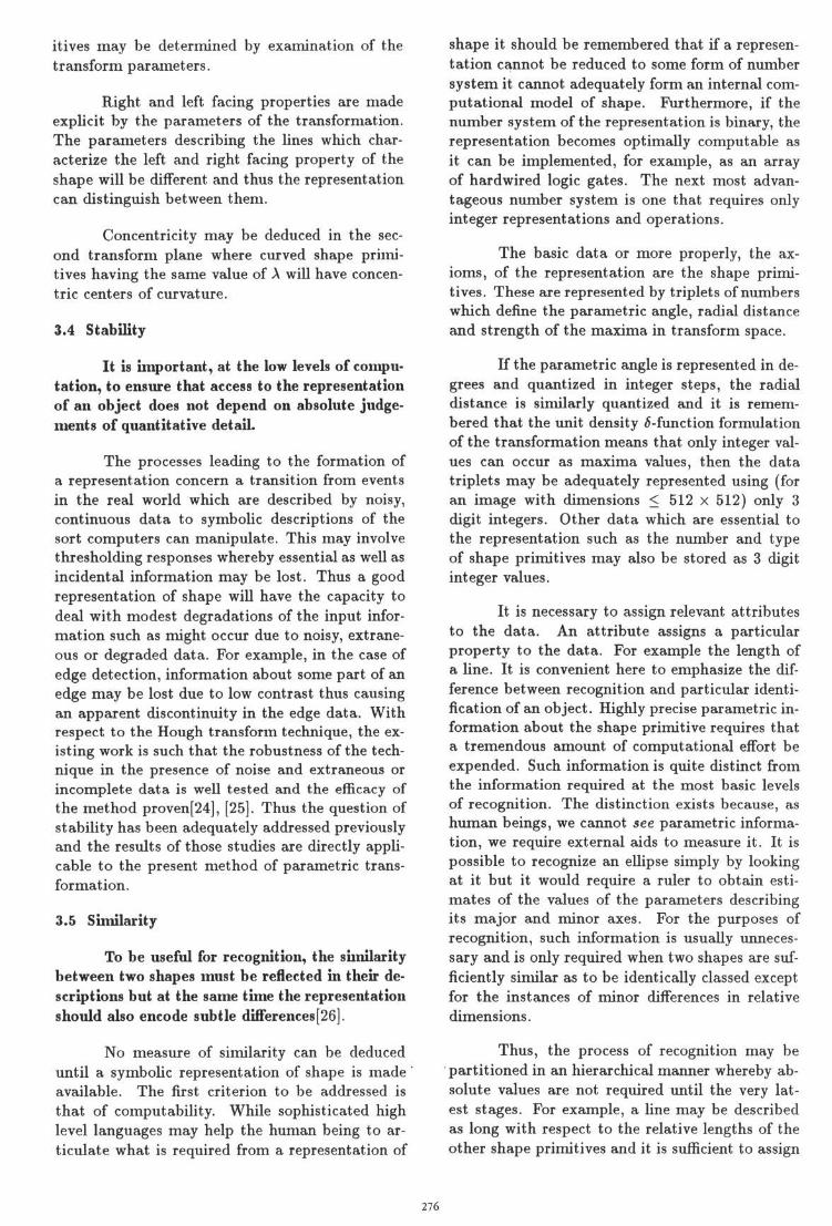
binary edge image into its constituent shape prim-itives where those primitives are of two basic types,straight lines and arcs of conic sections. By wayof illustration, the binary image of a hand drawncurve is shown in Fig. 1. The binary data aretransformed and an intensity map of the resultingtransform plane is shown in Fig. 2. The resultof filtering the transform space to locate the max-ima associated with the curved shape primitivesis shown in Fig. 3. The transform space is thenfiltered in order to locate the maxima associatedwith the straight line shape primitives the resultsof this operation are shown in Fig. 4. A secondtransformation process (of the filtered transformplane shown in Fig. 3 is then required and a sec-ond filtering operation. The results of these twooperations are shown in Fig. 5 and Fig. 6.
The method generates efficient shape primi-tives that are sufficient to decompose a binary edgeimage of a curve into its constituent straight linesand, (to some predetermined resolution)[12], arcsof conic section.
3.3 Geometric and Spatial Relations
It is not sufficient to decompose the im-age into its constituent shape primitives, in addi-tion, the representation should also make explicitthe geometric and spatial relations between thoseshape primitives
Once the transformation and filtering pro-cesses are complete, the parameters associated withthe shape primitives are known. These parametersare labelled p and 9 for the first transformation andv and A for the second transformation. Inspectionof the parameters will yield the geometric proper-ties and relative spatial arrangements of the shapeprimitives.
Parallelism between pairs of straight linesmay be deduced by inspection and grouping of allof the shape primitives having the same value of9.
Knowledge of the relative lengths of the prim-itives may be obtained from the transformation inthe following way. Each point on a straight linewill contribute a value of 1 to the value of themaxima in transform space associated with thatstraight line. The value of the maxima may thusbe used as a measure of the length of the line. Sim-ilarly for the curved shape primitives, the value ofthe maxima in the second transform space associ-ated with a curved shape primitive in the imagespace will be a measure of the relative length ofthat curved shape primitive.
The symmetry between particular shape prim-
275
itives may be determined by examination of thetransform parameters.
Right and left facing properties are madeexplicit by the parameters of the transformation.The parameters describing the lines which char-acterize the left and right facing property of theshape will be different and thus the representationcan distinguish between them.
Concentricity may be deduced in the sec-ond transform plane where curved shape primi-tives having the same value of A will have concen-tric centers of curvature.
3.4 Stability
It is important, at the low levels of compu-tation, to ensure that access to the representationof an object does not depend on absolute judge-ments of quantitative detail.
The processes leading to the formation ofa representation concern a transition from eventsin the real world which are described by noisy,continuous data to symbolic descriptions of thesort computers can manipulate. This may involvethresholding responses whereby essential as well asincidental information may be lost. Thus a goodrepresentation of shape will have the capacity todeal with modest degradations of the input infor-mation such as might occur due to noisy, extrane-ous or degraded data. For example, in the case ofedge detection, information about some part of anedge may be lost due to low contrast thus causingan apparent discontinuity in the edge data. Withrespect to the Hough transform technique, the ex-isting work is such that the robustness of the tech-nique in the presence of noise and extraneous orincomplete data is well tested and the efficacy ofthe method proven[24], [25]. Thus the question ofstability has been adequately addressed previouslyand the results of those studies are directly appli-cable to the present method of parametric trans-formation.
3.5 Similarity
To be useful for recognition, the similaritybetween two shapes must be reflected in their de-scriptions but at the same time the representationshould also encode subtle differences[26].
No measure of similarity can be deduceduntil a symbolic representation of shape is made 'available. The first criterion to be addressed isthat of computability. While sophisticated highlevel languages may help the human being to ar-ticulate what is required from a representation of
shape it should be remembered that if a represen-tation cannot be reduced to some form of numbersystem it cannot adequately form an internal com-putational model of shape. Furthermore, if thenumber system of the representation is binary, therepresentation becomes optimally computable asit can be implemented, for example, as an arrayof hardwired logic gates. The next most advan-tageous number system is one that requires onlyinteger representations and operations.
The basic data or more properly, the ax-ioms, of the representation are the shape primi-tives. These are represented by triplets of numberswhich define the parametric angle, radial distanceand strength of the maxima in transform space.
If the parametric angle is represented in de-grees and quantized in integer steps, the radialdistance is similarly quantized and it is remem-bered that the unit density ^-function formulationof the transformation means that only integer val-ues can occur as maxima values, then the datatriplets may be adequately represented using (foran image with dimensions < 512 X 512) only 3digit integers. Other data which are essential tothe representation such as the number and typeof shape primitives may also be stored as 3 digitinteger values.
It is necessary to assign relevant attributesto the data. An attribute assigns a particularproperty to the data. For example the length ofa line. It is convenient here to emphasize the dif-ference between recognition and particular identi-fication of an object. Highly precise parametric in-formation about the shape primitive requires thata tremendous amount of computational effort beexpended. Such information is quite distinct fromthe information required at the most basic levelsof recognition. The distinction exists because, ashuman beings, we cannot see parametric informa-tion, we require external aids to measure it. It ispossible to recognize an ellipse simply by lookingat it but it would require a ruler to obtain esti-mates of the values of the parameters describingits major and minor axes. For the purposes ofrecognition, such information is usually unneces-sary and is only required when two shapes are suf-ficiently similar as to be identically classed exceptfor the instances of minor differences in relativedimensions.
Thus, the process of recognition may bepartitioned in an hierarchical manner whereby ab-solute values are not required until the very lat-est stages. For example, a line may be describedas long with respect to the relative lengths of theother shape primitives and it is sufficient to assign
276

or not assign such a property to a shape primi-tive, i.e., a line is either long or not long. In ad-dition, such an attribute as length is a particularconcept, i.e. there is no dependence between par-ticular items of data. This means that such anattribute may be expressed as strings of binarydigits. For example a rectangle may be labelledwith respect to length as:
Length = (0,1,0,1) = 0101
where it is understood that each digit representsthe assignment of the attribute long to an orderedlist of the shape primitives which form the 4 sidesof the rectangle.
It is necessary to assign relational conceptsand structural properties to the data. These areexpressed by linking the data in some structuredway. Again it is only necessary to use booleantruth values in the assignment of those relationalattributes. For example, the line labelled a is ei-ther parallel to the line labelled b or it is not. Arelational concept may thus be represented by theelements of a two dimensional matrix. Where twoelements are related by the concept then a truthvalue is obtained. Where no such relation existsthen a zero or false value is obtained. It is notedthat, using such a representation, the ordering ofthe shape primitives, once fixed, is not significant.
Once a symbolic representation of shape hasbeen made available, it then becomes possible toevaluate and compare representations and to de-termine the similarities and differences betweenparticular instances of image data.
3.6 Saliency
The representation should be such that grossor salient features associated with shape can bemade explicit and used to bring essential informa-tion to the foreground allowing smaller and moreeasily manipulated descriptions to suffice. Theability to extract two or three salient primitivecomponents means that objects can be quickly recog-nised even when they are partially occluded ortheir images are extensively degraded[18].
Salient features may be extracted by sim-ply determining the pair or triplet of shape prim-itives having the greatest or near greatest valuesof transform maxima. The method first takes cen-trally positioned model images, transforms thoseimages; filters the transformed images for maximaand stores, as triplets of data, the information as-sociated with those maxima. The data triplets areordered on the strength of the maxima. The top-most pair or triplet of data sets from this ordered
list become the salient features for that particularobject.
Knowing that each description of an objecta set salient features does not help to distinguishone particular object from another. The angle be-tween the salient shape primitives is different inthe case of each model image and, because angu-lar differences are invariant under the operationsof translation, rotation and scaling, the differencebetween images may be expressed by these angu-lar differences, A0£-odc!, between the salient shapeprimitives.
A description of the object is constructedin the following way. The angular differences, A0,and the differences between radial distances, Ar,are calculated for each member of the ordered listwith respect to each other member of the list. Theresults are stored as a matrix where the upper tri-angle of the matrix contains information about theangular differences, A^JJ*Offe, and the lower trian-gle contains information about the differences inangular distance, Ar^af fe. The matrix so formedis refered to as Dima9e (A0O-, Arfj). For angulardifferences > TT/2 the value w - A0 is stored. Asimilar constraint is applied to the values of A0 ex-tracted from the images. This is necessary whenthe transform plane is represented in the ranges[0,ir] and [-p,p].
Once all the salient features are known theymay be used to identify a particular image. Detailsof a relevant study are given in [12].
3.7 Invariance
Information that is the basis of recognitionshould be invariant to the operations of transla-tion, rotation and scaling.
It is a generally accepted principle that thesymbolic description of an object will be repre-sented in an object centred co-ordinate system butthat the image input will be represented in a viewercentred co-ordinate system. This is a classic com-puter vision problem: matching an internal de-scription of shape with an instance of image datawhen the two are described with respect to twodifferent co-ordinate systems. To be useful, a rep-resentation of shape should offer invariance underthe operations of translation, rotation and scalingand should make explicit the viewer-object corre-spondence.
Using the present technique, the viewer-objectorientation correspondence may be recovered inthe following way.
Once the object has been identified by its
277
salient features, it is then possible to match par-ticular shape primitives in the image with theircorresponding shape primitives in the computer'sinternal model of the identified object in the fol-lowing way:
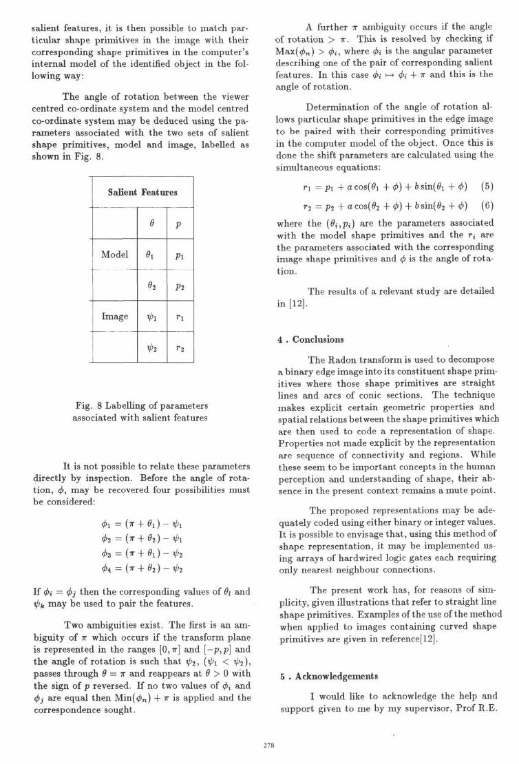
The angle of rotation between the viewercentred co-ordinate system and the model centredco-ordinate system may be deduced using the pa-rameters associated with the two sets of salientshape primitives, model and image, labelled asshown in Fig. 8.
Salient Features
Model
Image
1|
9
Ox
o2
V>i
V'2
P
Pi
P2
Fig. 8 Labelling of parametersassociated with salient features
It is not possible to relate these parametersdirectly by inspection. Before the angle of rota-tion, <f>, may be recovered four possibilities mustbe considered:
fa = O r + 0 2 ) - V'lfa = {v + 9i) - fa
fa = (^ + 02)-1p2
If (j>i = <f>j then the corresponding values of 6i andV>fc may be used to pair the features.
Two ambiguities exist. The first is an am-biguity of IT which occurs if the transform planeis represented in the ranges [0,7r] and [— p,p] andthe angle of rotation is such that tp2, (V'l < V'2),passes through 6 = IT and reappears at 6 > 0 withthe sign of p reversed. If no two values of <j>i and<f>j are equal then Min((/>n) + w is applied and thecorrespondence sought.
A further TT ambiguity occurs if the angleof rotation > TT. This is resolved by checking ifMax(<£n) > <f>i, where fa is the angular parameterdescribing one of the pair of corresponding salientfeatures. In this case 4>i |-+ fa + v a n ( langle of rotation.
1S
Determination of the angle of rotation al-lows particular shape primitives in the edge imageto be paired with their corresponding primitivesin the computer model of the object. Once this isdone the shift parameters are calculated using thesimultaneous equations:
=Pl +a cos(0i
a cos(02r2 = P2
6 sin(0i
b sin(02
(5)
(6)
where the {6i,Pi) are the parameters associatedwith the model shape primitives and the r,- arethe parameters associated with the correspondingimage shape primitives and <f> is the angle of rota-tion.
The results of a relevant study are detailedin [12].
4 . Conclusions
The Radon transform is used to decomposea binary edge image into its constituent shape prim-itives where those shape primitives are straightlines and arcs of conic sections. The techniquemakes explicit certain geometric properties andspatial relations between the shape primitives whichare then used to code a representation of shape.Properties not made explicit by the representationare sequence of connectivity and regions. Whilethese seem to be important concepts in the humanperception and understanding of shape, their ab-sence in the present context remains a mute point.
The proposed representations may be ade-quately coded using either binary or integer values.It is possible to envisage that, using this method ofshape representation, it may be implemented us-ing arrays of hardwired logic gates each requiringonly nearest neighbour connections.
The present work has, for reasons of sim-plicity, given illustrations that refer to straight lineshape primitives. Examples of the use of the methodwhen applied to images containing curved shapeprimitives are given in reference [12].
5 . Acknowledgements
I would like to acknowledge the help andsupport given to me by my supervisor, Prof R.E.
278
Burge, Head of the Physics Dept. at King's Col-lege. The work presented in this paper was fi-nanced by the National Physical Laboratory, Ted-dington, Middx. under extra mural research con-tract no. EMRM 82-0437 with the support of Mr.Ed Brocklehurst of that Institution.
References
[1] Hu M. Visual pattern recognition by mo-ment invariants IRE Trans, on inform, the-ory, IT-8, 179-187, 1962.
[2] Duda R. and Hart P., Pattern classificationand scene analysts, Wiley 1973.
[3] Zahn C.T. and Roskies R.Z. Fourier de-scriptors for plane closed curves, IEEE Trans,on computers, C-21, 269-281, 1972
[4] Freeman H. Computer processing of line draw-ings images, Computing Surveys, 57-97, March1974.
[5] Latto A., Mumford D. and Shah J. Therepresentation of shape, IEEE Workshop oncomputer vision, Anapolis, 1984.
[6] Brady M.J. and Asada H. Smoothed Lo-cal Symmetries and their implementations,MIT Artificial Intelligence Lab. Memo 757,Febuary 1984.
[7] Asada H. and Brady M. The curvature pri-mal sketch IEEE Trans, on Pattern Anal,and Mach. Intell., Vol PAMI-8, No 1, Jan-uary 1986.
[8] Hough P.V.C. Method and means for Recog-nising complex patterns. U.S. Patent No.3069654, 1962
[9] Radon J. Uber die Bestimmung von Funk-tionen durch ihre Integralwerte langs gewisserMannigfaltigkeiten. Berichte SachsischeAkademie der Wissenschaften Leipzig, Math-Phys Kl., 69, 262-267 , 1917.
[10] Illingworth J. and Kittler J. A survey ofefficient Hough Transform methods, AlveyVision Club Meeting, Cambridge.
[11] Gerig G. and Klein F. Fast contour iden-tification through efficient Hough transformand simplified interpretation strategies. Proc.8th Int. Conf. Pattern Recognition, Vol 1,Paris 1986.
[12] Leavers V.F. Submitted as part of a PhDThesis, Shape Parametrisation and Object
Recognition in Machine Vision London Uni-versity, June 1988.
[13] Gel'fand I.M., Graev M.I. and Vilenkin N.Ya.Generalized functions Vol 5, Academic Press,New York, 1966.
[14] Leavers V.F. and Miller G.F. The RadonTransformation of 6-function curves. A ge-ometric Approach, Alvey Vision Conference,Cambridge 1987.
[15] Leavers V.F. and Boyce J.F. The Radontransform and its application to shape de-tection in computer vision, Image and Vi-sion Computing Vol.5, May 1987.
[16] Marr D. Computer Vision W. H. Freeman,1980.
[17] Brady M. Criteria for shape representations,Human and Machine Vision, Beck J. andRosenfeld A. eds. Academic press, 1983
[18] Biedermann I. Human image understand-ing: recent research and theory, ComputerVision Graphics and Image Processing, Vol32, 29-73, 1985.
[19] O'Rourke J. and Sloan K.R. Dynamic quan-tisation: two adaptive data structures formultidimensional spaces, IEEE T-PAMI, Vol6, 1984
[20] Li H., Lavin M.A. and LeMaster R.J. FastHough Trans/orm Proc. of 3rd workshop oncomputer vision: Bellair, Michgan 1985
[21] Li H. Fast Hough Transform for multidi-mensional signal processing, IBM Researchreport, RC 11562, York Town Heights 1985
[22] Illingworth J. and Kittler J. The adaptiveHough transform in press IEEE T-PAMI1987
[23] Leavers V.F. and Sandier M. B. An efficientRadon transform BPRA 4th InternationalConf., Cambridge, 1988.
[24] Shapiro S.D. Transformation for the com-puter detection of curves in noisy pictures,Computer Graphics and Image processing,Vol 4, 328-338, December 1975.
[25] Shapiro S.D. and Iannino A. Geometric con-structions for predicting Hough transformperformance, IEEE Trans. Pattern Anal,and Mach. Intell., Vol PAMI-1, 310-317,July 1979.
279
Fig.l Binary image of curve Fig.4 Straight line filter
Fig.2 First transform Fig.5 Second transform
Fig.3 Curve filtering process Fig.6 Filtered Second transform280


![11.[23 36]quadrature radon transform for smoother tomographic reconstruction](https://img.pdfslide.net/doc/110x75/54825b12b07959520c8b478b/1123-36quadrature-radon-transform-for-smoother-tomographic-reconstruction.jpg)