Embed Size (px)
Citation preview
HPE StoreEver MSL2024, MSL4048,MSL8048, and MSL8096 Tape LibrariesUser and Service Guide
Part Number: Q6Q62-00024aPublished: February 2018Edition: 10
AbstractThis guide provides information on installing, configuring, upgrading, and troubleshooting the tapelibrary. This guide is intended for system administrators and other users who need physical andfunctional knowledge of the tape library.
© Copyright 2006, 2007, 2010, 2012, 2015, 2018 Hewlett Packard Enterprise Development LP
NoticesThe information contained herein is subject to change without notice. The only warranties for Hewlett PackardEnterprise products and services are set forth in the express warranty statements accompanying suchproducts and services. Nothing herein should be construed as constituting an additional warranty. HewlettPackard Enterprise shall not be liable for technical or editorial errors or omissions contained herein.
Confidential computer software. Valid license from Hewlett Packard Enterprise required for possession, use,or copying. Consistent with FAR 12.211 and 12.212, Commercial Computer Software, Computer SoftwareDocumentation, and Technical Data for Commercial Items are licensed to the U.S. Government undervendor's standard commercial license.
Links to third-party websites take you outside the Hewlett Packard Enterprise website. Hewlett PackardEnterprise has no control over and is not responsible for information outside the Hewlett Packard Enterprisewebsite.
AcknowledgmentsIntel®, Itanium®, Pentium®, Intel Inside®, and the Intel Inside logo are trademarks of Intel Corporation in theUnited States and other countries.
Microsoft® and Windows® are either registered trademarks or trademarks of Microsoft Corporation in theUnited States and/or other countries.
Adobe® and Acrobat® are trademarks of Adobe Systems Incorporated.
Java® and Oracle® are registered trademarks of Oracle and/or its affiliates.
UNIX® is a registered trademark of The Open Group.
Contents
Features........................................................................................................9MSL2024 front panel........................................................................................................................... 9MSL4048 front panel......................................................................................................................... 10MSL8048 and MSL8096 front panel.................................................................................................. 11MSL2024 back panel.........................................................................................................................12MSL4048 back panel.........................................................................................................................13MSL8048 and MSL8096 back panel................................................................................................. 13Power supply back panel (MSL4048, MSL8048 and MSL8096) ......................................................14Controller health status indicator.......................................................................................................14Tape drive back panels......................................................................................................................15
Tape drive power indicator......................................................................................................16Library options ..................................................................................................................................16
Redundant power supply........................................................................................................17HPE StoreEver 1/8 G2 Tape Autoloader and MSL Tape Libraries Encryption Kit ................. 17Command View TL TapeAssure............................................................................................. 17LTFS Support..........................................................................................................................18MSL8048 upgrade license......................................................................................................18HPE MSL Library Extender.....................................................................................................18
Hardware-based encryption ............................................................................................................. 20KMIP-based key servers.........................................................................................................20Application-managed encryption............................................................................................ 21
Logical libraries..................................................................................................................................21MSL2024 and MSL8048 Tape Libraries partitions..................................................................22MSL4048 and MSL8096 Tape Libraries partitions..................................................................22
Control path and data path failover................................................................................................... 24
Installing the tape library.......................................................................... 25Location requirements.......................................................................................................................25FC connection information.................................................................................................................27SAS connection information.............................................................................................................. 28Parallel SCSI configuration information.............................................................................................29Preparing the host............................................................................................................................. 32Unpacking the shipping container..................................................................................................... 33Removing the shipping lock ..............................................................................................................33Installing the library in a rack ............................................................................................................34Installing the tabletop conversion kit..................................................................................................36Installing tape drives..........................................................................................................................37Installing a redundant power supply..................................................................................................39Changing the SCSI address (parallel SCSI drives only)................................................................... 39Connecting the FC cable...................................................................................................................40Connecting the SAS cable.................................................................................................................40Connecting the parallel SCSI cable...................................................................................................41Powering on the library .....................................................................................................................42Configuring the library ...................................................................................................................... 42
Recommended FC interface configuration............................................................................. 43Verifying the connection.................................................................................................................... 44Labeling the tape cartridges.............................................................................................................. 44Verifying the installation.....................................................................................................................45
Downloading product firmware............................................................................................... 45
Contents 3
Configuring additional features..........................................................................................................46
Tape cartridges and magazines................................................................47Tape cartridges..................................................................................................................................47
LTO-7 Type M media for LTO-8 drives....................................................................................47Recommended practices for using and maintaining tape cartridges......................................47Recommended practices for labeling tape cartridges.............................................................48Write-protecting data cartridges..............................................................................................49Read and write compatibility...................................................................................................50Supported media.................................................................................................................... 51
Magazines......................................................................................................................................... 52MSL2024 magazine slot numbering....................................................................................... 53MSL4048 magazine slot numbering....................................................................................... 53MSL8048 and MSL8096 magazine slot numbering................................................................54
Operating the library ................................................................................ 57The remote management interface (RMI)......................................................................................... 57
Overview of the RMI............................................................................................................... 57Logging in to the library.......................................................................................................... 58Status pane.............................................................................................................................59The Help link...........................................................................................................................61Identity ................................................................................................................................... 61
The Identity > Library page.......................................................................................... 61The Identity > Drive page.............................................................................................63The Identity > Network page........................................................................................65
Status......................................................................................................................................66The Status > Library page........................................................................................... 66The Status > Drive page.............................................................................................. 68The Status > Inventory page .......................................................................................70The Status > Security page......................................................................................... 72
Configuration.......................................................................................................................... 73The Configuration > System page............................................................................... 73The Configuration > Security page.............................................................................. 79The Configuration > Drive page...................................................................................79The Configuration > License Key page........................................................................81The Configuration > Network page.............................................................................. 81The Configuration > Network Management page........................................................ 83The Configuration > Password page........................................................................... 85The Configuration > Date/Time page...........................................................................86The Configuration > Log page..................................................................................... 87The Configuration > Alerts page.................................................................................. 87The Configuration > Save/Restore page..................................................................... 88
Operations.............................................................................................................................. 88The Operations > Move Media page........................................................................... 89The Operations > Inventory page................................................................................ 89The Operations > Magazines page..............................................................................89
Support................................................................................................................................... 90The Support > General Diagnostic page..................................................................... 90The Support > Service page— Service restricted .......................................................90The Support > Firmware page..................................................................................... 90The Support > Reboot page ....................................................................................... 91The Support > Library Logs page................................................................................ 91The Support > Drive page ...........................................................................................92The Support > Support Ticket page............................................................................. 92
4 Contents
Using the MSL2024 OCP ................................................................................................................. 94LED indicators........................................................................................................................ 95Home screen ......................................................................................................................... 95OCP buttons........................................................................................................................... 96The OCP menu structure........................................................................................................97
Entering the administrator password........................................................................... 98Unlocking the mailslot (Unlock Mailslot)................................................................................. 98Status/Information...................................................................................................................99
Viewing cartridge inventory (Status/Information > Inventory)...................................... 99Viewing library information (Status/Information> Library Information) ...................... 101Viewing drive information (Status/Information > Drive Information)...........................102Viewing component status (Status/Information > Component Status).......................102Viewing network information (Status/Information > Network Information)................. 103
Configuring the library...........................................................................................................103Configuring logical libraries (Status/Information > Set Logical Libraries).................. 104Changing the administrator password (Configuration > Change Admin Password)..104Setting the number of reserved slots (Configuration > Set Reserved Slot Count).....105Configuring the mailslot (Configuration > Configure Mailslot)....................................105Configuring the bar code reporting format (Configuration > Barcode FormatReporting).................................................................................................................. 105Changing the SCSI address — parallel SCSI drives (Configuration> ChangeDrive)......................................................................................................................... 106Changing the drive configuration — Fibre Channel drives (Configuration>Change Drive)............................................................................................................106Setting the master drive (Configuration > Set Master Drive)..................................... 107Setting behaviors (Configuration > Library behavior) ............................................... 108Setting the date and time (Configuration > Library Date/Time) .................................109Configuring IPv4 network settings (Configuration > Configure Network Settings).....110Configuring automatic cleaning (Configuration > Configure Auto Cleaning)..............110Restoring factory defaults (Configuration > Restore Defaults)................................... 111Saving the library configuration (Configuration> Save/Restore Configuration) .........112Restoring the library configuration (Configuration> Save/Restore Configuration) .... 112
Accessing the operations functions...................................................................................... 113Unlocking, removing, and replacing magazines (Operations > Unlock Left orRight Magazine)......................................................................................................... 113Cleaning a tape drive (Operations > Clean Drive) .................................................... 114Moving tapes in the library (Operations > Move Tape) ..............................................115Updating tape cartridge inventory (Operations > Perform Inventory).........................116Rebooting the library (Operations > Reboot Library) ................................................ 116Enabling password locks (Operations > Enable Library Password Locks) ............... 116
Accessing the support functions........................................................................................... 116Powering a drive on or off (Support > Power On/Off Drive) ...................................... 117Running the demonstration (Support > Run Demo)...................................................117Running the slot to slot test (Support > Run Slot To Slot Test).................................. 118Running the wellness test (Support > Run Wellness Test)........................................ 118Upgrading firmware (Support > Library FW Upgrade) .............................................. 119Upgrading drive firmware from a USB flash drive (Support> Drive FW Upgrade) ....120Upgrading drive firmware from a firmware upgrade tape (Support> Drive FWUpgrade) ...................................................................................................................120Viewing logs (Support > Library Error Log) ...............................................................121Downloading a support ticket (Support > Download Support Ticket).........................121Forcing the drive to eject a tape (Support > Force Drive To Eject Tape)................... 122
Using the MSL4048, MSL8048, and MSL8096 OCP ..................................................................... 122Overview...............................................................................................................................122
Operations available using the OCP..........................................................................122OCP navigation buttons.............................................................................................123
Using the OCP......................................................................................................................124
Contents 5
Status message bar...................................................................................................125Menu bar....................................................................................................................126Setting the administrator password............................................................................127
Illustrated menu option and navigation examples.................................................................128Opening mailslots (Operations > Open Mailslots)..................................................... 128Unlocking, removing, and replacing magazines (Operations > Unlock Left/RightMagazines)................................................................................................................ 131Moving Media (Operations > Move Media)................................................................131
Info menu..............................................................................................................................133Viewing status information (Info > Status)................................................................. 133Viewing identity information (Info > Identity Library).................................................. 133Viewing identity information (Info > Identity Drives)...................................................134Viewing inventory information (Info > Inventory)........................................................134Viewing network information (Info > Network)........................................................... 134
Configuration menu.............................................................................................................. 134Changing the number of logical libraries (Configuration > Logical Libraries)............ 135Changing the library configuration (Configuration > Library)..................................... 135Changing the drive configuration (Configuration > Drives)........................................ 137Changing the network configuration (Configuration > Network)................................ 137Barcode reporting format (Configuration > Barcode Reporting)................................ 137Setting and changing the administrator password (Configuration> Set AdminPassword)..................................................................................................................137Restore defaults (Configuration > Restore Defaults)................................................. 138Setting the library date and time (Configuration > Set Date and Time)..................... 139Saving and restoring the library configuration (Configuration> Save/Restore)..........139
Operations menu.................................................................................................................. 139Opening the mailslot (Operations > Open Mailslot)................................................... 140Unlocking, removing, and replacing magazines (Operations > Unlock Left/RightMagazines)................................................................................................................ 140Moving Media (Operations > Move Media)................................................................141Performing Inventory (Operations > Inventory)..........................................................141Enabling Password Locks (Operations > Enable Password Locks).......................... 141
Support menu....................................................................................................................... 141Powering drives on and off (Support > Power on/off Drives)..................................... 141Cleaning the tape drive (Support > Clean Drive)....................................................... 141Running tests (Support > Run Tests).........................................................................142Viewing logs (Support > View Logs).......................................................................... 142Updating library and drive firmware (Support > FW Upgrade)...................................142Force ejecting a drive (Support > Force Drive Eject).................................................144Downloading a support ticket (Support > Support Ticket)..........................................144Rebooting the tape library (Support > Reboot).......................................................... 144
Troubleshooting information and procedures......................................145The library displays errors............................................................................................................... 145Fibre Channel connection problems................................................................................................145Detection problems after installing a SAS drive.............................................................................. 146Detection problems after installing a parallel SCSI drive.................................................................147Operation problems.........................................................................................................................151Performance problems.................................................................................................................... 159
Average file size................................................................................................................... 160File storage system ..............................................................................................................160Connection from the backup server to the disk array........................................................... 160Backup/archive server.......................................................................................................... 160Backup/archive software and method...................................................................................161Connection from the archive/backup host server to the library ............................................161
6 Contents
Data cartridges..................................................................................................................... 161Tape drive read or write performance seems slow............................................................... 161
Service and repair........................................................................................................................... 162Releasing the magazines manually......................................................................................162
The wellness test.............................................................................................................................163Running the wellness test.....................................................................................................165
Error codes......................................................................................................................................166Finding error code information on the MSL2024 OCP .........................................................166Finding error code information on the MSL4048, MSL8048 and MSL8096 OCP ................167Finding error code information on the RMI........................................................................... 168Generating a report or support ticket from L&TT..................................................................169Downloading a support ticket from the library.......................................................................169Viewing a downloaded support ticket................................................................................... 169Finding error code information on an L&TT support ticket or report.....................................169Main error code descriptions................................................................................................ 171Error sub-code descriptions..................................................................................................188Drive error codes.................................................................................................................. 198
Warning events................................................................................................................................198Configuration change events...........................................................................................................208Information events...........................................................................................................................210Diagnosing problems with Library & Tape Tools.............................................................................. 211
Upgrading and servicing the library ..................................................... 213Possible tools needed..................................................................................................................... 213Installing a new tape drive...............................................................................................................214Replacing a tape drive.....................................................................................................................216Removing and replacing a magazine.............................................................................................. 219
Removing a magazine using the MSL2024 OCP ................................................................ 219Removing a magazine using the MSL4048, MSL8048 and MSL8096 OCP ....................... 219Releasing magazines using the RMI ................................................................................... 220Releasing the magazine using the manual magazine release............................................. 220
Installing a redundant power supply (MSL4048, MSL8048, and MSL8096 only) ...........................221Replacing the power supply (MSL4048, MSL8048 and MSL8096) ................................................223Replacing the library controller (MSL4048, MSL8048 and MSL8096) ........................................... 224Removing and replacing the base chassis......................................................................................226
Removing the tape cartridge from the tape drive..................................................................227Removing the cables, magazines, and tape drive ...............................................................227Removing the power supply and library controller (MSL4048, MSL8048 and MSL8096only) .....................................................................................................................................228Removing the base chassis..................................................................................................229Installing the replacement chassis........................................................................................230Replacing the tabletop conversion cover..............................................................................231Replacing the library components and cables......................................................................231Verifying the chassis replacement........................................................................................ 232
Websites................................................................................................... 233
Support and other resources................................................................. 234Accessing Hewlett Packard Enterprise Support..............................................................................234Accessing updates.......................................................................................................................... 234Customer self repair........................................................................................................................ 235Remote support...............................................................................................................................235Warranty information....................................................................................................................... 235
Contents 7
Regulatory information.................................................................................................................... 236Documentation feedback.................................................................................................................236
Technical specifications..........................................................................237Physical specifications.....................................................................................................................237Environmental specifications...........................................................................................................238Electrical specifications................................................................................................................... 238Regulatory specifications.................................................................................................................239Regulatory compliance identification numbers................................................................................240Default and restore defaults settings...............................................................................................240
Electrostatic discharge........................................................................... 243Preventing electrostatic damage..................................................................................................... 243Grounding methods.........................................................................................................................243
Warranty and regulatory information ....................................................244Warranty information....................................................................................................................... 244Regulatory information.................................................................................................................... 244
Belarus Kazakhstan Russia marking....................................................................................244Turkey RoHS material content declaration........................................................................... 245Ukraine RoHS material content declaration..........................................................................245
8 Contents
FeaturesThe HPE StoreEver MSL2024, MSL4048, MSL8048, and MSL8096 Tape Libraries provide compact, high-capacity, low-cost solutions for simple, unattended data backup. This unique design houses up to 12 tapecartridges for each U of height. Tape cartridges can be accessed through removable magazines and one ormore mailslots. Each magazine holds up to 12 tape cartridges.
The libraries are compatible with most operating systems. However, the libraries require either direct supportfrom the operating system or a compatible backup application to take full advantage of their many features. Toverify compatibility, see the BURA Data Agile Compatibility Matrix at http://www.hpe.com/storage/DAPRcompatibility.
The libraries are customer expandable with exchangeable tape drives. The libraries support Ultrium full-heightand half-height tape drives. To see the tape drives currently available for each tape library, see the MSLQuickSpecs at http://www.hpe.com/storage/msl. For a list of all supported configurations, see the Businessclass libraries drive matrix on the BURA Data Agile website at http://www.hpe.com/storage/DAPRcompatibility.
The library provides two user interfaces:
• Remote management interface (RMI)—With the RMI you can monitor and operate the library from awebpage. You can access most library functions from the RMI. See The remote management interface(RMI) on page 57.
• Operator control panel (OCP)—With the OCP you can monitor and operate the library from the front panel.
◦ MSL2024: See Using the MSL2024 OCP on page 94.
◦ MSL4048, MSL8048 and MSL8096: See Using the MSL4048, MSL8048, and MSL8096 OCP on page122.
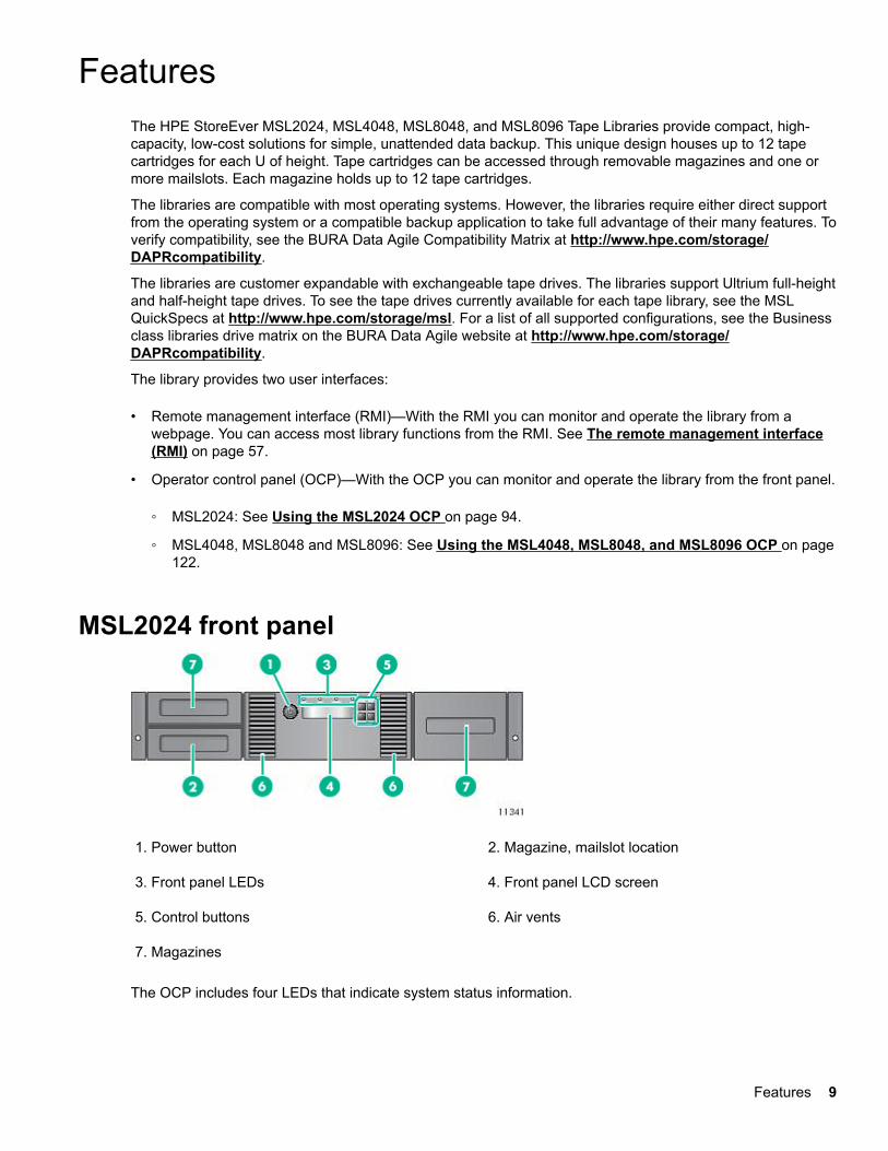
MSL2024 front panel
1. Power button 2. Magazine, mailslot location
3. Front panel LEDs 4. Front panel LCD screen
5. Control buttons 6. Air vents
7. Magazines
The OCP includes four LEDs that indicate system status information.
Features 9
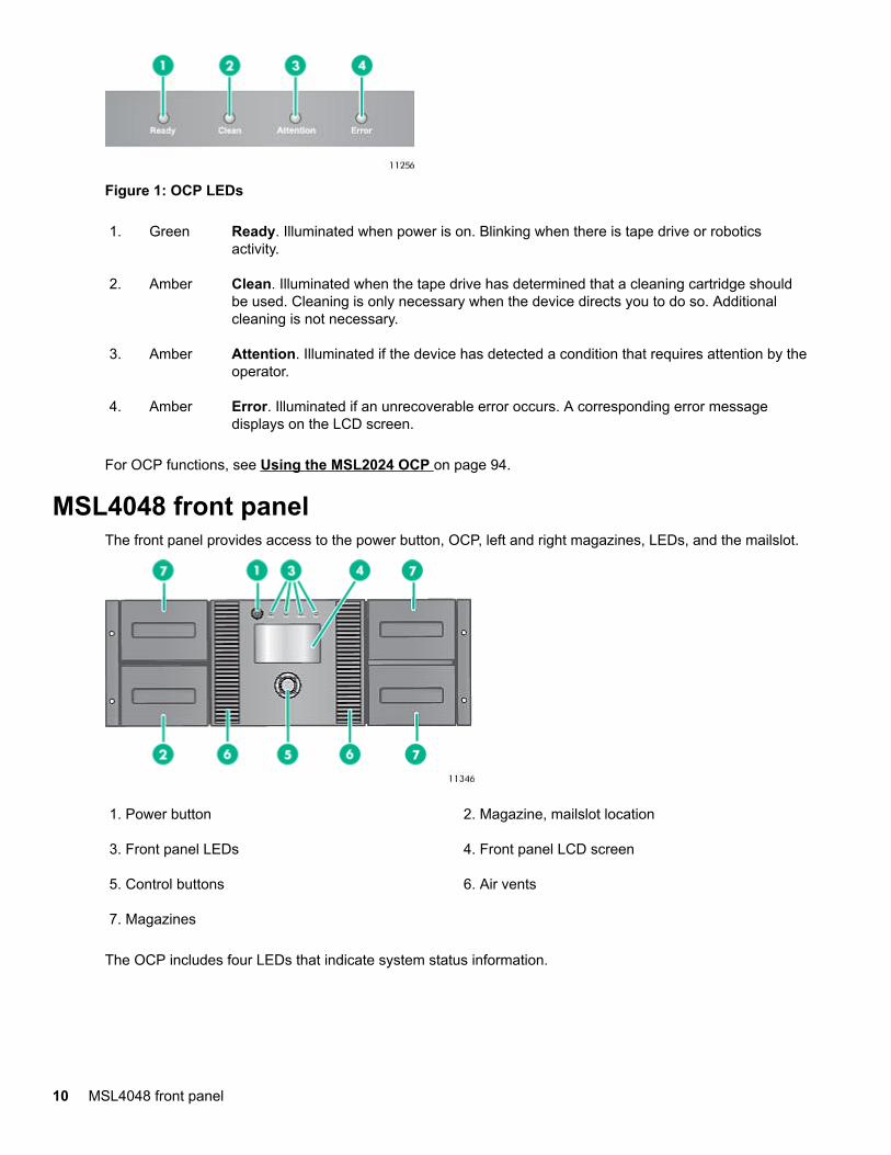
Figure 1: OCP LEDs
1. Green Ready. Illuminated when power is on. Blinking when there is tape drive or roboticsactivity.
2. Amber Clean. Illuminated when the tape drive has determined that a cleaning cartridge shouldbe used. Cleaning is only necessary when the device directs you to do so. Additionalcleaning is not necessary.
3. Amber Attention. Illuminated if the device has detected a condition that requires attention by theoperator.
4. Amber Error. Illuminated if an unrecoverable error occurs. A corresponding error messagedisplays on the LCD screen.
For OCP functions, see Using the MSL2024 OCP on page 94.
MSL4048 front panelThe front panel provides access to the power button, OCP, left and right magazines, LEDs, and the mailslot.
1. Power button 2. Magazine, mailslot location
3. Front panel LEDs 4. Front panel LCD screen
5. Control buttons 6. Air vents
7. Magazines
The OCP includes four LEDs that indicate system status information.
10 MSL4048 front panel
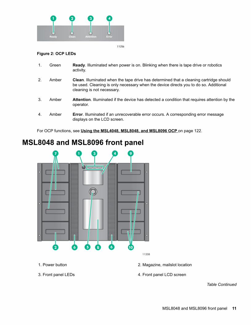
Figure 2: OCP LEDs
1. Green Ready. Illuminated when power is on. Blinking when there is tape drive or roboticsactivity.
2. Amber Clean. Illuminated when the tape drive has determined that a cleaning cartridge shouldbe used. Cleaning is only necessary when the device directs you to do so. Additionalcleaning is not necessary.
3. Amber Attention. Illuminated if the device has detected a condition that requires attention by theoperator.
4. Amber Error. Illuminated if an unrecoverable error occurs. A corresponding error messagedisplays on the LCD screen.
For OCP functions, see Using the MSL4048, MSL8048, and MSL8096 OCP on page 122.
MSL8048 and MSL8096 front panel
1. Power button 2. Magazine, mailslot location
3. Front panel LEDs 4. Front panel LCD screen
Table Continued
MSL8048 and MSL8096 front panel 11
5. Control buttons 6. Air vents
7. Magazine 8. Observation window
9. 12-slot mailslot (MSL8096 only) 10. Magazine (MSL8096 only)
The OCP includes four LEDs that indicate system status information.
Figure 3: OCP LEDs
1. Green Ready. Illuminated when power is on. Blinking when there is tape drive or roboticsactivity.
2. Amber Clean. Illuminated when the tape drive has determined that a cleaning cartridge shouldbe used. Cleaning is only necessary when the device directs you to do so. Additionalcleaning is not necessary.
3. Amber Attention. Illuminated if the device has detected a condition that requires attention by theoperator.
4. Amber Error. Illuminated if an unrecoverable error occurs. A corresponding error messagedisplays on the LCD screen. For more information, see The library displays errors onpage 145.
For OCP functions, see Using the MSL4048, MSL8048, and MSL8096 OCP on page 122 .
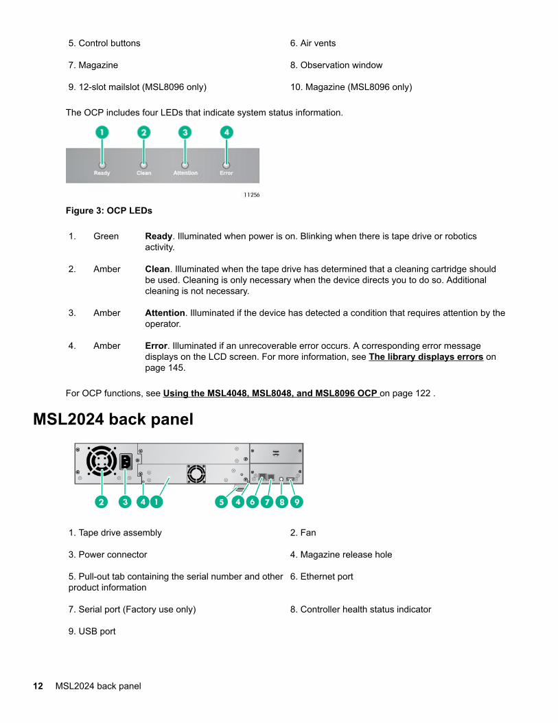
MSL2024 back panel
1. Tape drive assembly 2. Fan
3. Power connector 4. Magazine release hole
5. Pull-out tab containing the serial number and otherproduct information
6. Ethernet port
7. Serial port (Factory use only) 8. Controller health status indicator
9. USB port
12 MSL2024 back panel
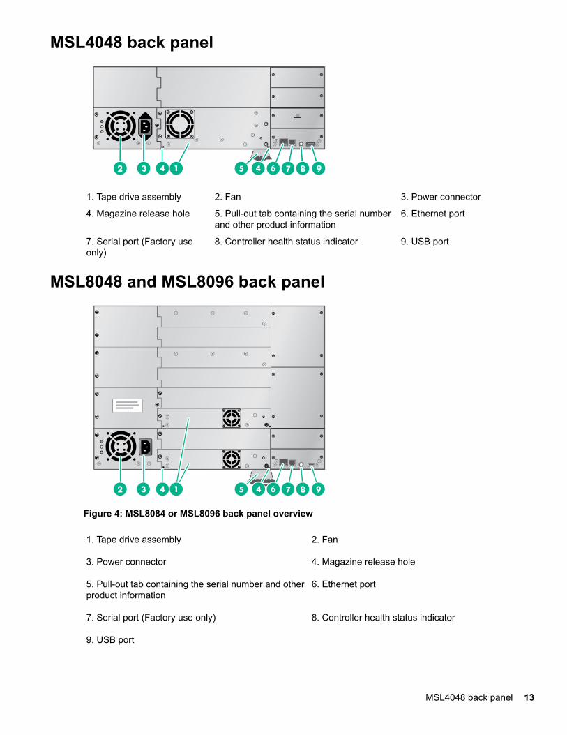
MSL4048 back panel
1. Tape drive assembly 2. Fan 3. Power connector
4. Magazine release hole 5. Pull-out tab containing the serial numberand other product information
6. Ethernet port
7. Serial port (Factory useonly)
8. Controller health status indicator 9. USB port
MSL8048 and MSL8096 back panel
Figure 4: MSL8084 or MSL8096 back panel overview
1. Tape drive assembly 2. Fan
3. Power connector 4. Magazine release hole
5. Pull-out tab containing the serial number and otherproduct information
6. Ethernet port
7. Serial port (Factory use only) 8. Controller health status indicator
9. USB port
MSL4048 back panel 13
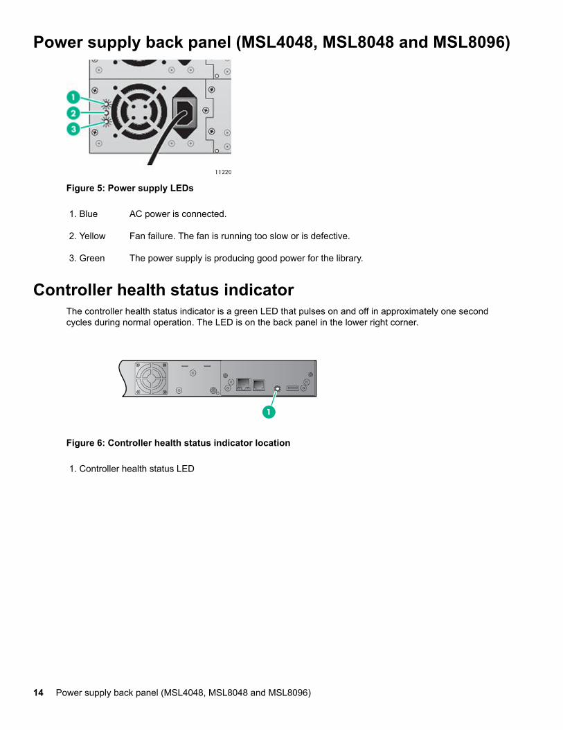
Power supply back panel (MSL4048, MSL8048 and MSL8096)
Figure 5: Power supply LEDs
1. Blue AC power is connected.
2. Yellow Fan failure. The fan is running too slow or is defective.
3. Green The power supply is producing good power for the library.
Controller health status indicatorThe controller health status indicator is a green LED that pulses on and off in approximately one secondcycles during normal operation. The LED is on the back panel in the lower right corner.
Figure 6: Controller health status indicator location
1. Controller health status LED
14 Power supply back panel (MSL4048, MSL8048 and MSL8096)
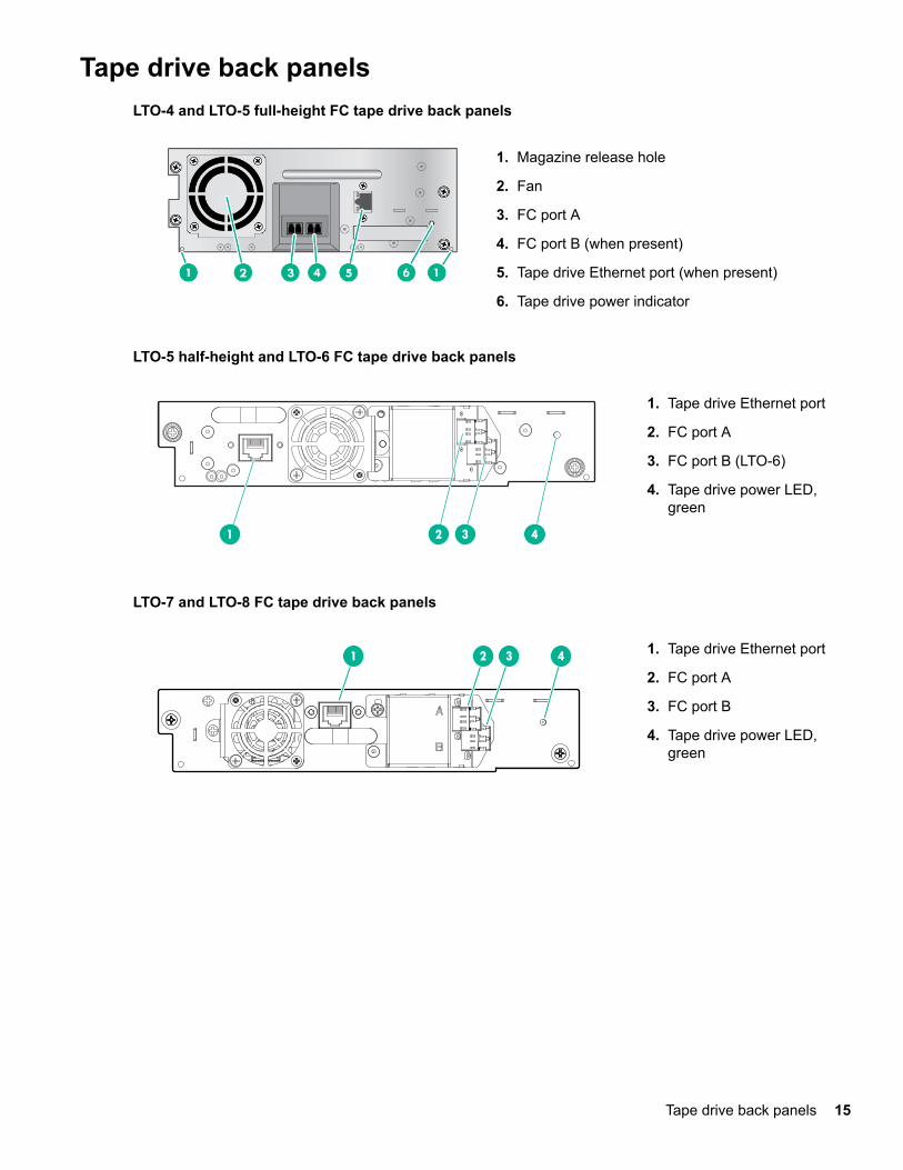
Tape drive back panelsLTO-4 and LTO-5 full-height FC tape drive back panels
1. Magazine release hole
2. Fan
3. FC port A
4. FC port B (when present)
5. Tape drive Ethernet port (when present)
6. Tape drive power indicator
LTO-5 half-height and LTO-6 FC tape drive back panels
1 2 3 4
1. Tape drive Ethernet port
2. FC port A
3. FC port B (LTO-6)
4. Tape drive power LED,green
LTO-7 and LTO-8 FC tape drive back panels
1 2 3 4 1. Tape drive Ethernet port
2. FC port A
3. FC port B
4. Tape drive power LED,green
Tape drive back panels 15
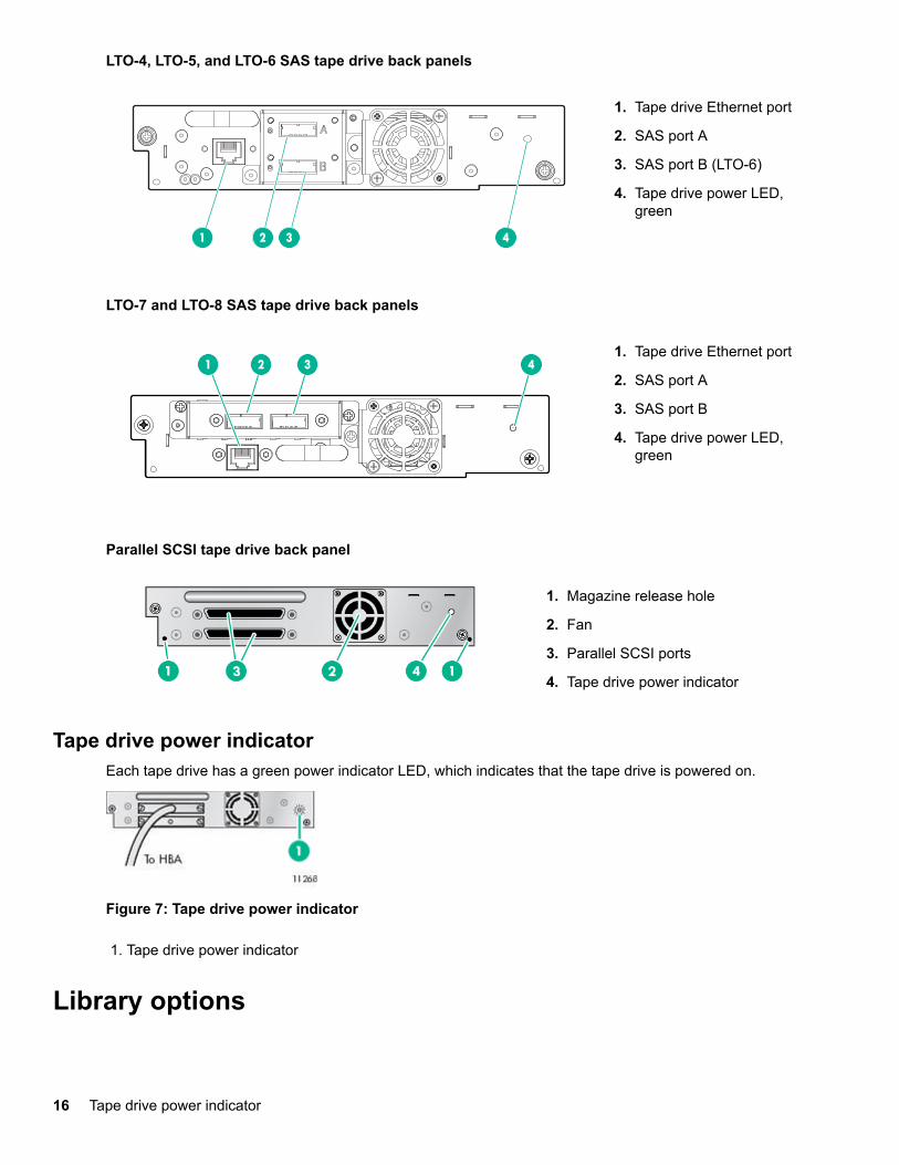
LTO-4, LTO-5, and LTO-6 SAS tape drive back panels
1 2 3 4
1. Tape drive Ethernet port
2. SAS port A
3. SAS port B (LTO-6)
4. Tape drive power LED,green
LTO-7 and LTO-8 SAS tape drive back panels
1 2 3 41. Tape drive Ethernet port
2. SAS port A
3. SAS port B
4. Tape drive power LED,green
Parallel SCSI tape drive back panel
1. Magazine release hole
2. Fan
3. Parallel SCSI ports
4. Tape drive power indicator
Tape drive power indicatorEach tape drive has a green power indicator LED, which indicates that the tape drive is powered on.
Figure 7: Tape drive power indicator
1. Tape drive power indicator
Library options
16 Tape drive power indicator
Redundant power supplyThe MSL4048, MSL8048, and MSL8096 tape libraries have a redundant power supply option. The redundantpower supply allows the library to continue operating when one power supply fails. With the redundant powersupply system, the library can monitor the status of each power supply and power supply fan. The redundantpower supply can be installed without powering off the library.
For instructions on installing the redundant power supply, see Installing a redundant power supply.
HPE StoreEver 1/8 G2 Tape Autoloader and MSL Tape Libraries Encryption KitThe encryption kit provides secure generation and storage of encryption keys. The encryption kit can be usedwith any StoreEver 1/8 G2 Tape Autoloader or MSL2024, MSL3040, MSL4048, MSL6480, MSL8048, andMSL8096 Tape Library with at least one LTO-4 or later generation tape drive. The encryption kit cannot beused with the MSL6000.
The encryption kit supports your manual security policies and procedures by providing secure storage forencryption keys. Access to the key server tokens and their backup files is protected with user-specifiedpasswords. You will need to create processes to protect the tokens and secure the passwords.
Before enabling the encryption kit, verify that the library is running the most current firmware to ensurecompatibility between the token and library.
To use the encryption kit, insert a key server token in the USB port on the back of the library and then enablethe encryption kit and configure the token from the RMI.
IMPORTANT:
When encryption is enabled with the encryption kit, the library will not use encryption keys from othersources, such as a key management system or application software. Disable encryption in applicationswriting to the library when encryption is enabled with the encryption kit. Applications that attempt tocontrol encryption while encryption is enabled with the encryption kit will not be able to do so, which cancause backups or other write operations to fail.
For information about configuring and using the encryption kit, see the encryption kit user guide, which isavailable from the Hewlett Packard Enterprise Information Library at http://www.hpe.com/info/storage/docs.
Command View TL TapeAssureHPE Command View TL software provides a browser-based GUI for remote management and monitoring ofmost Hewlett Packard Enterprise libraries. With Command View TL, you can view and analyze theperformance and health of supported tape drives and media in multiple devices at the same time. In addition,TapeAssure displays more extensive drive and media health information than is visible in the RMI.
Command View TL software is installed on a management station. The management station can also be usedto manage HPE EML and ESL Tape Libraries. For best performance, locate the management station in thesame physical location and on the same IP subnet as the library. Command View TL software is available fordownload without charge from the Hewlett Packard Enterprise website at http://www.hpe.com/storage/cvtldownload.
For information on installing and using Command View TL, see the HPE Interface Manager and CommandView TL User Guide, available from the information library: http://www.hpe.com/info/storage/docs
Command View TL support is included in all library firmware that supports LTO-5 and later generation tapedrives. To find and download the most up-to-date firmware revision, visit the Hewlett Packard Enterprisesupport website at http://www.hpe.com/support/hpesc.
Redundant power supply 17
LTFS SupportThe HPE StoreOpen Automation application simplifies use of the Linear Tape File System (LTFS)functionality. LTFS makes tape self-describing, file-based, and easy-to-use. The automation applicationextends LTFS functionality, presenting an autoloader or library and its tape cartridges as a collection offolders. This extension results in easy data access and management. For more information about LTFScapabilities, see http://www.hpe.com/storage/StoreOpen.
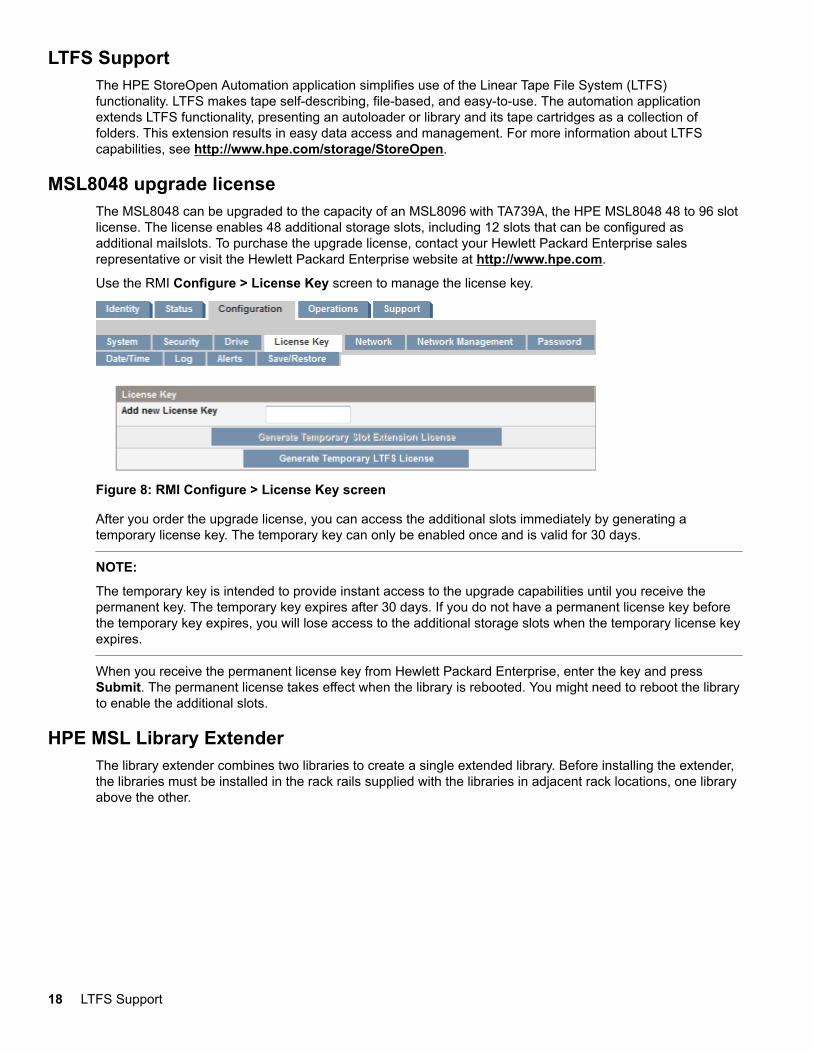
MSL8048 upgrade licenseThe MSL8048 can be upgraded to the capacity of an MSL8096 with TA739A, the HPE MSL8048 48 to 96 slotlicense. The license enables 48 additional storage slots, including 12 slots that can be configured asadditional mailslots. To purchase the upgrade license, contact your Hewlett Packard Enterprise salesrepresentative or visit the Hewlett Packard Enterprise website at http://www.hpe.com.
Use the RMI Configure > License Key screen to manage the license key.
Figure 8: RMI Configure > License Key screen
After you order the upgrade license, you can access the additional slots immediately by generating atemporary license key. The temporary key can only be enabled once and is valid for 30 days.
NOTE:
The temporary key is intended to provide instant access to the upgrade capabilities until you receive thepermanent key. The temporary key expires after 30 days. If you do not have a permanent license key beforethe temporary key expires, you will lose access to the additional storage slots when the temporary license keyexpires.
When you receive the permanent license key from Hewlett Packard Enterprise, enter the key and pressSubmit. The permanent license takes effect when the library is rebooted. You might need to reboot the libraryto enable the additional slots.
HPE MSL Library ExtenderThe library extender combines two libraries to create a single extended library. Before installing the extender,the libraries must be installed in the rack rails supplied with the libraries in adjacent rack locations, one libraryabove the other.
18 LTFS Support
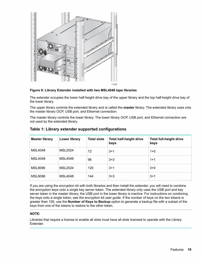
Figure 9: Library Extender installed with two MSL4048 tape libraries
The extender occupies the lower half-height drive bay of the upper library and the top half-height drive bay ofthe lower library.
The upper library controls the extended library and is called the master library. The extended library uses onlythe master library OCP, USB port, and Ethernet connection.
The master library controls the lower library. The lower library OCP, USB port, and Ethernet connection arenot used by the extended library.
Table 1: Library extender supported configurations
Master library Lower library Total slots Total half-height drivebays
Total full-height drivebays
MSL4048 MSL2024 72 3+1 1+0
MSL4048 MSL4048 96 3+3 1+1
MSL8096 MSL2024 120 3+1 3+0
MSL8096 MSL4048 144 3+3 3+1
If you are using the encryption kit with both libraries and then install the extender, you will need to combinethe encryption keys onto a single key server token. The extended library only uses the USB port and keyserver token in the master library; the USB port in the lower library is inactive. For instructions on combiningthe keys onto a single token, see the encryption kit user guide. If the number of keys on the two tokens isgreater than 100, use the Number of Keys to Backup option to generate a backup file with a subset of thekeys from one of the tokens to restore to the other token.
NOTE:
Libraries that require a license to enable all slots must have all slots licensed to operate with the LibraryExtender.
Features 19
Hardware-based encryptionThe LTO-4 and later generation tape drives include hardware capable of encrypting data while writing data,and decrypting data when reading. Hardware encryption can be used with or without compression whilemaintaining the full speed and capacity of the tape drive and media.
Encryption is the process of changing data into a form that cannot be read until it is deciphered with the keyused to encrypt the data. Encryption protects the data from unauthorized access and use. LTO tape drivesuse the 256-bit version of the industry-standard AES encrypting algorithm to protect your data.
To use this feature, you need:
• The 1/8 G2 & MSL Encryption Kit or a KMIP-based key server or a backup application that supportshardware encryption.
• LTO-4 or later generation media; no encryption will be performed when writing LTO-3 and earliergenerations of tape.
Your company policy will determine when to use encryption. For example, your company could requireencryption of company confidential and financial data, but not for personal data. Company policy will alsodefine how to generate and manage encryption keys. Backup applications that support encryption willgenerate a key for you or allow you to enter a key manually.
For information about using the encryption kit, see HPE StoreEver 1/8 G2 Tape Autoloader and MSL TapeLibraries Encryption Kit on page 17.
KMIP-based key serversThe library supports integration with encryption key management servers using the Key ManagementInteroperability Protocol (KMIP) standard. KMIP is an industry standard protocol for communications betweena key management server and an encryption system. The KMIP technical committee of the OASIS standardsbody (Organization for the Advancement of Structured Information Standards) developed the KMIPspecification.
The KMIP feature allows the library to obtain encryption keys from selected KMIP-compliant key managers.These keys can be used to encrypt data as it is written to tape. Up to six key servers can be configured forfailover purposes.
For instructions on configuring the KMIP feature, see the HPE StoreEver MSL Tape Libraries Encryption KeyServer Configuration Guide, available from the Enterprise Information Library at http://www.hpe.com/info/storage/docs.
Key managers
To use the KMIP feature, the library must have access to a KMIP key manager. Hewlett Packard Enterpriseonly supports KMIP when used with a supported key manager, listed in the compatibility matrix at http://www.hpe.com/storage/DAPRcompatibility.
Operation
When the KMIP feature is enabled and properly configured, tape data will automatically be encrypted withkeys delivered from the KMIP key manager. Tapes are encrypted on a key-per-tape basis.
Write, and append operations: The tape drive will request a key when data is written. The library, acting asan intermediary, can request the key manager to create a key. The library then obtains that key and delivers itto the tape drive. A name, which is associated with the media identifier, identifies the key. The key is notretained in the tape drive any longer than necessary to perform encryption operations.
Read operations: The tape drive will request a key. The library, acting as an intermediary, obtains the keyidentifier, requests that key from the key manager, and delivers it to the tape drive. The key is not retained inthe tape drive any longer than necessary to perform decryption operations.
20 Hardware-based encryption
Licensing
The KMIP feature requires that the StoreEver MSL2024/4048/8096 KMIP license has been installed beforethe feature can be enabled and configured.
Application-managed encryptionHardware encryption is off by default and is switched on by settings in your backup application. The backupapplication also generates and supplies the encryption key. Your backup application must support hardwareencryption for this feature to work. For a current list of suitable backup software, see the compatibility matrixat: http://www.hpe.com/storage/DAPRcompatibility
NOTE:
The library can only obtain encryption keys from one source. Using the encryption kit will prevent application-managed encryption.
Encryption is primarily designed to protect the media once it is offline and to prevent it being accessed fromanother machine. The tape drive can read and append the encrypted media without being prompted for a keywhile the machine and application that first encrypted the tape are accessing the tape.
There are two main instances when you will need to know the key:
• If you try to import the media to another machine or another instance of the backup application.
• If you are recovering your system after a disaster.
NOTE:
Encryption with keys that are generated directly from passwords or passphrases might be less secure thanencryption using truly random keys. Your application will explain the available options and methods. Refer tothe application user documentation for more information.
If you are unable to supply the key when requested to do so, no one will be able to access the encrypteddata, including support engineers.
This feature guarantees the security of your data, but also means that you must carefully manage theencryption key used to generate the tape.
CAUTION:
Keep a record or backup of your encryption keys and store it in a secure place separate from thecomputer running the backup software.
For detailed instructions about enabling encryption, see the documentation supplied with your backupapplication or with the encryption kit. The documentation will also highlight any default states, for examplewhen copying tapes, that might need to be changed when using encrypted tapes.
Logical librariesYou can configure a tape library with multiple tape drives into logical libraries. Each logical library mustcontain at least one tape drive. Each logical library is configured independently, allowing use by differentbackup applications and with different backup policies. For example, one logical library could perform abackup operation for one department while the second logical library restores data for another department.Data cartridges in one logical library cannot be shared with other logical libraries.
If the mailslot is enabled, all logical libraries have access to the mailslot. The tape library prohibits a cartridgethat was placed in the mailslot by one logical library from being moved into another logical library. The libraryallows a cartridge that was placed in the mailslot by the operator to be moved into any logical library. If
Application-managed encryption 21
sharing the mailslot among logical libraries is an issue in your environment or your backup application doesnot support mailslot sharing, disable the mailslot.
Each logical library has a unique serial number and World Wide Identifier (WWID), which can be found in theRMI Identity > Library screen.
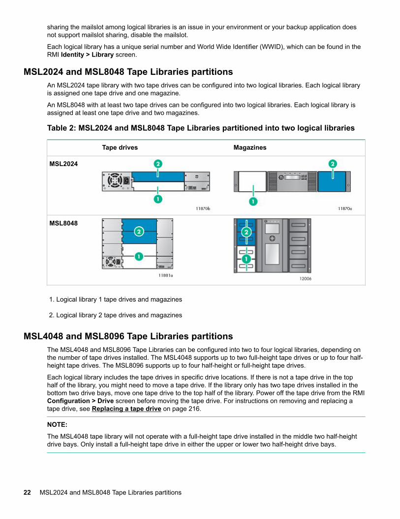
MSL2024 and MSL8048 Tape Libraries partitionsAn MSL2024 tape library with two tape drives can be configured into two logical libraries. Each logical libraryis assigned one tape drive and one magazine.
An MSL8048 with at least two tape drives can be configured into two logical libraries. Each logical library isassigned at least one tape drive and two magazines.
Table 2: MSL2024 and MSL8048 Tape Libraries partitioned into two logical libraries
Tape drives Magazines
MSL2024
MSL8048
1. Logical library 1 tape drives and magazines
2. Logical library 2 tape drives and magazines
MSL4048 and MSL8096 Tape Libraries partitionsThe MSL4048 and MSL8096 Tape Libraries can be configured into two to four logical libraries, depending onthe number of tape drives installed. The MSL4048 supports up to two full-height tape drives or up to four half-height tape drives. The MSL8096 supports up to four half-height or full-height tape drives.
Each logical library includes the tape drives in specific drive locations. If there is not a tape drive in the tophalf of the library, you might need to move a tape drive. If the library only has two tape drives installed in thebottom two drive bays, move one tape drive to the top half of the library. Power off the tape drive from the RMIConfiguration > Drive screen before moving the tape drive. For instructions on removing and replacing atape drive, see Replacing a tape drive on page 216.
NOTE:
The MSL4048 tape library will not operate with a full-height tape drive installed in the middle two half-heightdrive bays. Only install a full-height tape drive in either the upper or lower two half-height drive bays.
22 MSL2024 and MSL8048 Tape Libraries partitions
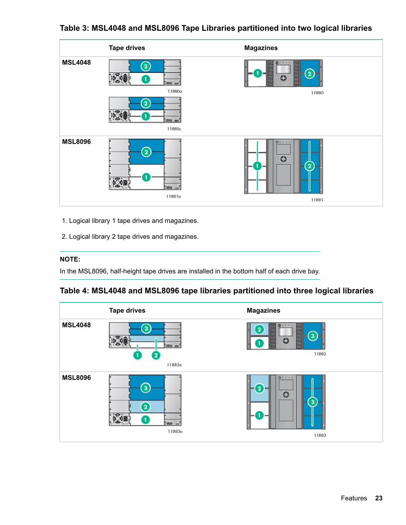
Table 3: MSL4048 and MSL8096 Tape Libraries partitioned into two logical libraries
Tape drives Magazines
MSL4048
MSL8096
1. Logical library 1 tape drives and magazines.
2. Logical library 2 tape drives and magazines.
NOTE:
In the MSL8096, half-height tape drives are installed in the bottom half of each drive bay.
Table 4: MSL4048 and MSL8096 tape libraries partitioned into three logical libraries
Tape drives Magazines
MSL4048
MSL8096
Features 23
1. Logical library 1 tape drive and magazines 2. Logical library 2 tape drive and magazines
3. Logical library 3 tape drives and magazines.
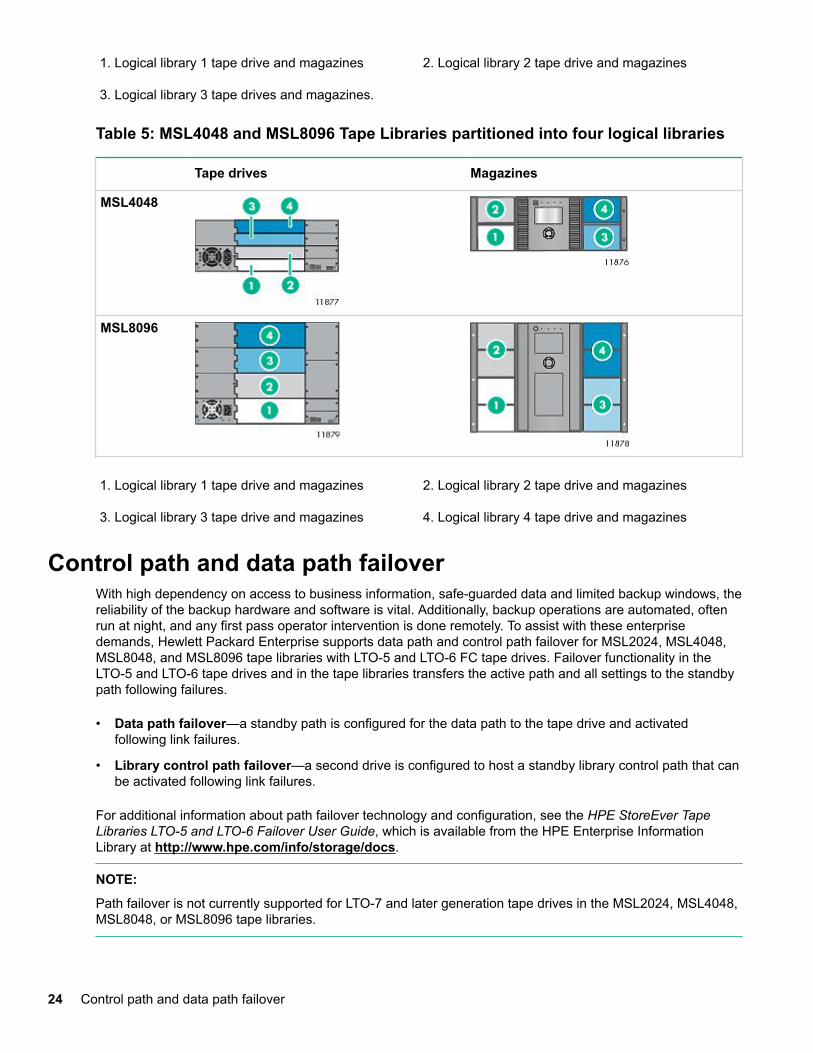
Table 5: MSL4048 and MSL8096 Tape Libraries partitioned into four logical libraries
Tape drives Magazines
MSL4048
MSL8096
1. Logical library 1 tape drive and magazines 2. Logical library 2 tape drive and magazines
3. Logical library 3 tape drive and magazines 4. Logical library 4 tape drive and magazines
Control path and data path failoverWith high dependency on access to business information, safe-guarded data and limited backup windows, thereliability of the backup hardware and software is vital. Additionally, backup operations are automated, oftenrun at night, and any first pass operator intervention is done remotely. To assist with these enterprisedemands, Hewlett Packard Enterprise supports data path and control path failover for MSL2024, MSL4048,MSL8048, and MSL8096 tape libraries with LTO-5 and LTO-6 FC tape drives. Failover functionality in theLTO-5 and LTO-6 tape drives and in the tape libraries transfers the active path and all settings to the standbypath following failures.
• Data path failover—a standby path is configured for the data path to the tape drive and activatedfollowing link failures.
• Library control path failover—a second drive is configured to host a standby library control path that canbe activated following link failures.
For additional information about path failover technology and configuration, see the HPE StoreEver TapeLibraries LTO-5 and LTO-6 Failover User Guide, which is available from the HPE Enterprise InformationLibrary at http://www.hpe.com/info/storage/docs.
NOTE:
Path failover is not currently supported for LTO-7 and later generation tape drives in the MSL2024, MSL4048,MSL8048, or MSL8096 tape libraries.
24 Control path and data path failover
Installing the tape libraryProcedure
1. Plan the installation.
• Location requirements
• FC configuration information
• SAS configuration information
• Parallel SCSI configuration information
2. Prepare the host
3. Unpack the shipping container
4. Remove the shipping lock
5. Install the library in a rack
6. Install the tabletop conversion kit
7. Install tape drives
8. Change the SCSI address (parallel SCSI drives only)
9. Connect the parallel SCSI cable
10. Connect the FC cable
11. Connect the SAS cable
12. Power on the library
13. Configure the library
14. Verify the connection
15. Label the tape cartridges
16. Verify the installation
17. Configure additional features
Location requirementsSelect an open rack location with access to the host server and a power outlet. If possible, install the library inthe middle or higher part of the rack to avoid dust from the floor and to allow easy access to the mailslot andmagazines.
IMPORTANT:
The library must be mounted on the enclosed rack rails. Placing the library on a surface, such as a tabletop or rack shelf, could result in library errors.
If installing the library with the library extender, determine the master and lower units, and install them inadjacent rack locations, with the master library directly above the lower library. To install the extender, bothlibraries must be installed in the rack rails.
Installing the tape library 25
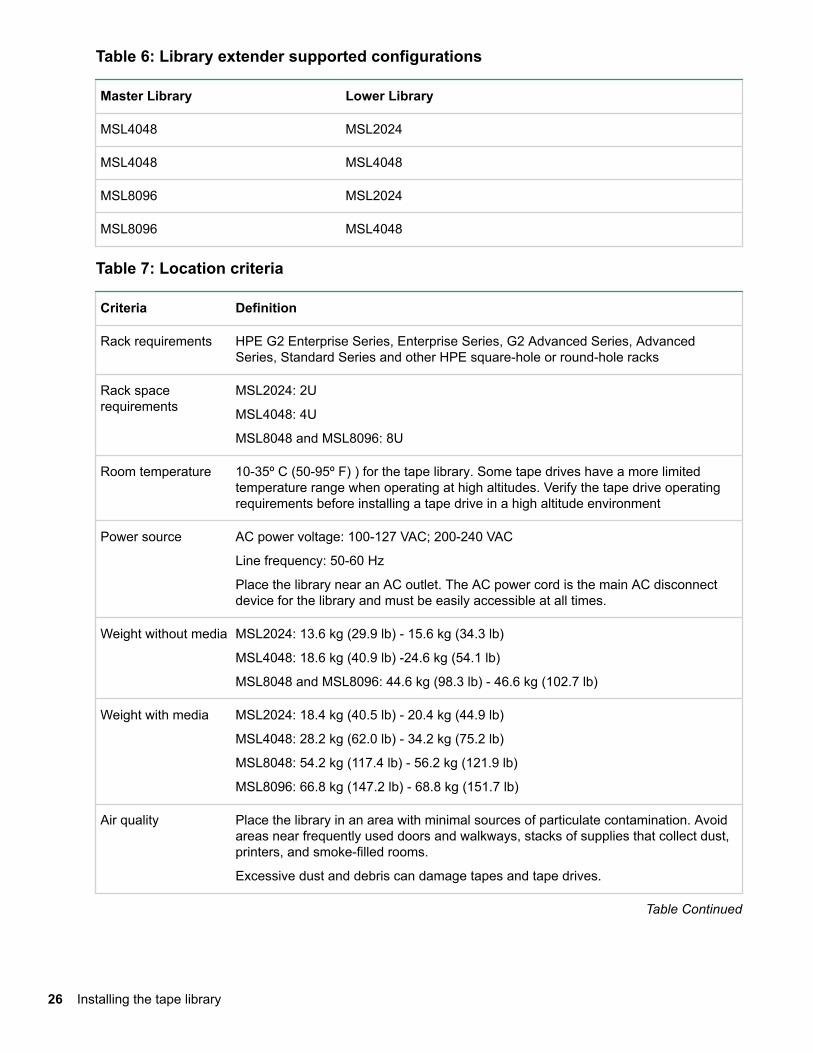
Table 6: Library extender supported configurations
Master Library Lower Library
MSL4048 MSL2024
MSL4048 MSL4048
MSL8096 MSL2024
MSL8096 MSL4048
Table 7: Location criteria
Criteria Definition
Rack requirements HPE G2 Enterprise Series, Enterprise Series, G2 Advanced Series, AdvancedSeries, Standard Series and other HPE square-hole or round-hole racks
Rack spacerequirements
MSL2024: 2U
MSL4048: 4U
MSL8048 and MSL8096: 8U
Room temperature 10-35º C (50-95º F) ) for the tape library. Some tape drives have a more limitedtemperature range when operating at high altitudes. Verify the tape drive operatingrequirements before installing a tape drive in a high altitude environment
Power source AC power voltage: 100-127 VAC; 200-240 VAC
Line frequency: 50-60 Hz
Place the library near an AC outlet. The AC power cord is the main AC disconnectdevice for the library and must be easily accessible at all times.
Weight without media MSL2024: 13.6 kg (29.9 lb) - 15.6 kg (34.3 lb)
MSL4048: 18.6 kg (40.9 lb) -24.6 kg (54.1 lb)
MSL8048 and MSL8096: 44.6 kg (98.3 lb) - 46.6 kg (102.7 lb)
Weight with media MSL2024: 18.4 kg (40.5 lb) - 20.4 kg (44.9 lb)
MSL4048: 28.2 kg (62.0 lb) - 34.2 kg (75.2 lb)
MSL8048: 54.2 kg (117.4 lb) - 56.2 kg (121.9 lb)
MSL8096: 66.8 kg (147.2 lb) - 68.8 kg (151.7 lb)
Air quality Place the library in an area with minimal sources of particulate contamination. Avoidareas near frequently used doors and walkways, stacks of supplies that collect dust,printers, and smoke-filled rooms.
Excessive dust and debris can damage tapes and tape drives.
Table Continued
26 Installing the tape library
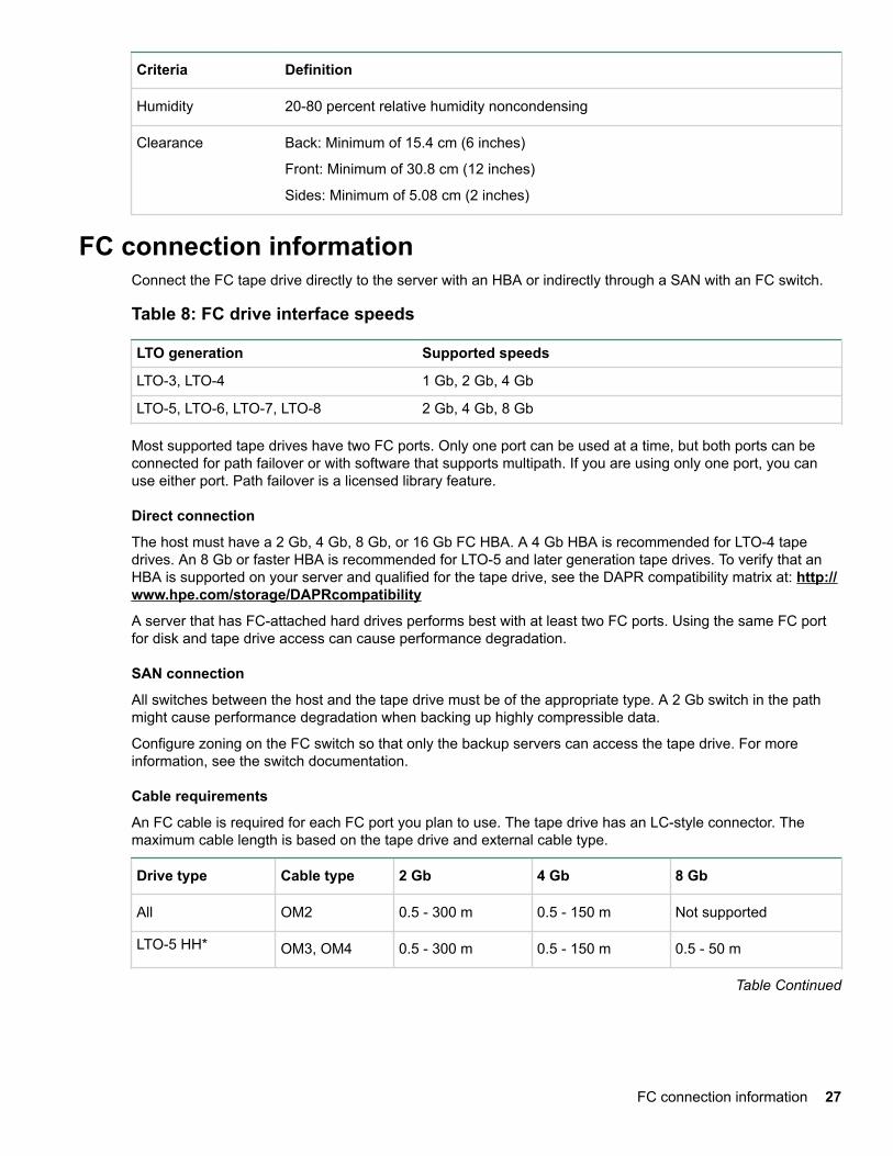
Criteria Definition
Humidity 20-80 percent relative humidity noncondensing
Clearance Back: Minimum of 15.4 cm (6 inches)
Front: Minimum of 30.8 cm (12 inches)
Sides: Minimum of 5.08 cm (2 inches)
FC connection informationConnect the FC tape drive directly to the server with an HBA or indirectly through a SAN with an FC switch.
Table 8: FC drive interface speeds
LTO generation Supported speeds
LTO-3, LTO-4 1 Gb, 2 Gb, 4 Gb
LTO-5, LTO-6, LTO-7, LTO-8 2 Gb, 4 Gb, 8 Gb
Most supported tape drives have two FC ports. Only one port can be used at a time, but both ports can beconnected for path failover or with software that supports multipath. If you are using only one port, you canuse either port. Path failover is a licensed library feature.
Direct connection
The host must have a 2 Gb, 4 Gb, 8 Gb, or 16 Gb FC HBA. A 4 Gb HBA is recommended for LTO-4 tapedrives. An 8 Gb or faster HBA is recommended for LTO-5 and later generation tape drives. To verify that anHBA is supported on your server and qualified for the tape drive, see the DAPR compatibility matrix at: http://www.hpe.com/storage/DAPRcompatibility
A server that has FC-attached hard drives performs best with at least two FC ports. Using the same FC portfor disk and tape drive access can cause performance degradation.
SAN connection
All switches between the host and the tape drive must be of the appropriate type. A 2 Gb switch in the pathmight cause performance degradation when backing up highly compressible data.
Configure zoning on the FC switch so that only the backup servers can access the tape drive. For moreinformation, see the switch documentation.
Cable requirements
An FC cable is required for each FC port you plan to use. The tape drive has an LC-style connector. Themaximum cable length is based on the tape drive and external cable type.
Drive type Cable type 2 Gb 4 Gb 8 Gb
All OM2 0.5 - 300 m 0.5 - 150 m Not supported
LTO-5 HH* OM3, OM4 0.5 - 300 m 0.5 - 150 m 0.5 - 50 m
Table Continued
FC connection information 27
Drive type Cable type 2 Gb 4 Gb 8 Gb
All except LTO-5 HH OM3, OM4 0.5 - 500 m 0.5 - 380 m 0.5 - 150 m
* The LTO-5 Ultrium 3000 half-height drive is shown as LTO-5 HH.
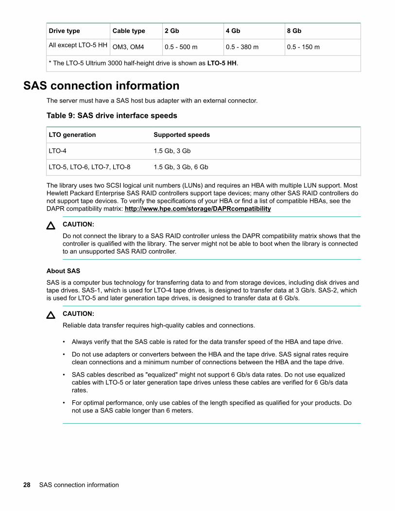
SAS connection informationThe server must have a SAS host bus adapter with an external connector.
Table 9: SAS drive interface speeds
LTO generation Supported speeds
LTO-4 1.5 Gb, 3 Gb
LTO-5, LTO-6, LTO-7, LTO-8 1.5 Gb, 3 Gb, 6 Gb
The library uses two SCSI logical unit numbers (LUNs) and requires an HBA with multiple LUN support. MostHewlett Packard Enterprise SAS RAID controllers support tape devices; many other SAS RAID controllers donot support tape devices. To verify the specifications of your HBA or find a list of compatible HBAs, see theDAPR compatibility matrix: http://www.hpe.com/storage/DAPRcompatibility
CAUTION:
Do not connect the library to a SAS RAID controller unless the DAPR compatibility matrix shows that thecontroller is qualified with the library. The server might not be able to boot when the library is connectedto an unsupported SAS RAID controller.
About SAS
SAS is a computer bus technology for transferring data to and from storage devices, including disk drives andtape drives. SAS-1, which is used for LTO-4 tape drives, is designed to transfer data at 3 Gb/s. SAS-2, whichis used for LTO-5 and later generation tape drives, is designed to transfer data at 6 Gb/s.
CAUTION:
Reliable data transfer requires high-quality cables and connections.
• Always verify that the SAS cable is rated for the data transfer speed of the HBA and tape drive.
• Do not use adapters or converters between the HBA and the tape drive. SAS signal rates requireclean connections and a minimum number of connections between the HBA and the tape drive.
• SAS cables described as "equalized" might not support 6 Gb/s data rates. Do not use equalizedcables with LTO-5 or later generation tape drives unless these cables are verified for 6 Gb/s datarates.
• For optimal performance, only use cables of the length specified as qualified for your products. Donot use a SAS cable longer than 6 meters.
28 SAS connection information
Cable requirements
SAS uses serial connections, with a direct connection between the host server and each of the storagedevices. This method eliminates the need to configure SCSI buses and assign SCSI IDs, as is required forparallel SCSI devices.
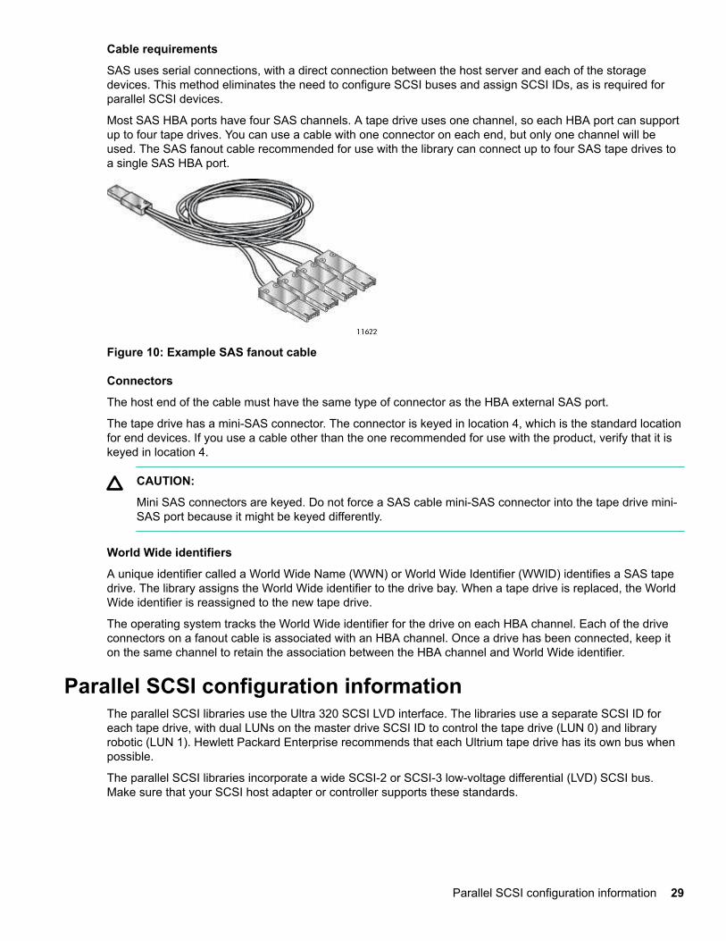
Most SAS HBA ports have four SAS channels. A tape drive uses one channel, so each HBA port can supportup to four tape drives. You can use a cable with one connector on each end, but only one channel will beused. The SAS fanout cable recommended for use with the library can connect up to four SAS tape drives toa single SAS HBA port.
Figure 10: Example SAS fanout cable
Connectors
The host end of the cable must have the same type of connector as the HBA external SAS port.
The tape drive has a mini-SAS connector. The connector is keyed in location 4, which is the standard locationfor end devices. If you use a cable other than the one recommended for use with the product, verify that it iskeyed in location 4.
CAUTION:
Mini SAS connectors are keyed. Do not force a SAS cable mini-SAS connector into the tape drive mini-SAS port because it might be keyed differently.
World Wide identifiers
A unique identifier called a World Wide Name (WWN) or World Wide Identifier (WWID) identifies a SAS tapedrive. The library assigns the World Wide identifier to the drive bay. When a tape drive is replaced, the WorldWide identifier is reassigned to the new tape drive.
The operating system tracks the World Wide identifier for the drive on each HBA channel. Each of the driveconnectors on a fanout cable is associated with an HBA channel. Once a drive has been connected, keep iton the same channel to retain the association between the HBA channel and World Wide identifier.
Parallel SCSI configuration informationThe parallel SCSI libraries use the Ultra 320 SCSI LVD interface. The libraries use a separate SCSI ID foreach tape drive, with dual LUNs on the master drive SCSI ID to control the tape drive (LUN 0) and libraryrobotic (LUN 1). Hewlett Packard Enterprise recommends that each Ultrium tape drive has its own bus whenpossible.
The parallel SCSI libraries incorporate a wide SCSI-2 or SCSI-3 low-voltage differential (LVD) SCSI bus.Make sure that your SCSI host adapter or controller supports these standards.
Parallel SCSI configuration information 29
IMPORTANT:
The libraries are NOT compatible with a high-voltage differential (HVD) SCSI bus. Do not put the libraryon a narrow (50-pin) parallel SCSI bus because doing so will severely degrade performance.
If the host computer will have multiple parallel SCSI devices, you must decide how they will be configured intoone or more parallel SCSI buses.
About parallel SCSI buses
A parallel SCSI bus consists of the host bus adapter (HBA), the parallel SCSI devices, the parallel SCSIcables, and the terminators. The HBA and devices are connected in a chain, with each device connected tothe next. The last device must have a SCSI terminator. Each device in the chain must have a unique SCSIaddress (SCSI ID).
Complex devices, such as the library, assign subaddresses, called logical unit numbers (LUNs), to differentparts of the device. The HBA and operating system must support multiple LUNs, also called LUN scanning,for the application software to operate the library. HPE Smart Array controllers, most third-party RAIDcontrollers, and many on-board SCSI controllers do not support multiple LUNs.
An HBA might have one or two channels, with each channel supporting one parallel SCSI bus. Check to seehow many channels the HBA has and what devices are already connected to the HBA. Some devices, suchas parallel SCSI disk drives, could be inside the server.
The devices on a parallel SCSI bus share bandwidth so be careful about which devices you put together on abus. Also, putting a single-ended (SE) SCSI device on the bus will slow all the devices on the bus down to SEspeed. To see what kind of parallel SCSI interface a device has, see the interface specifications for thedevice.
HBA requirements
For optimum performance, place each tape drive on its own parallel SCSI bus and use a host bus adapterthat can transfer data as fast as the library can read and write. Verify that the operating system supports theHBA. For best performance, use an Ultra 320 HBA. For current HBA compatibility information, see thecompatibility matrix at: http://www.hpe.com/storage/DAPRcompatability.
IMPORTANT:
Do not connect an LTO tape drive to an SE SCSI bus, as it severely degrades library performance. Asingle-ended SCSI host bus adapter severely degrades library performance and limits cable length.Also, if any SE devices are on the SCSI bus, all the devices on the bus slow down to SE speed,severely degrading performance.
Multiple LUN support
The library uses a single SCSI ID and two logical unit numbers (LUN). LUN 0 controls the tape drive and LUN1 controls the robotic. The library requires an HBA that supports multiple LUNs. If multiple LUN support is notenabled, the host computer cannot scan beyond LUN 0 to discover the library. It just sees the tape drive.
Parallel SCSI HPE Smart Array controllers, RAID controllers, and most on-board HBAs do not supportmultiple LUNs. For current HBA compatibility information, see the compatibility matrix at http://www.hpe.com/storage/DAPRcompatability.
IMPORTANT:
The library requires an HBA that supports multiple LUNs, which is also called “LUN scanning.”
30 Installing the tape library
Optimizing throughput
If possible, put each tape drive on its own parallel SCSI bus. For optimum performance, each LTO-4 tapedrive must be on its own Ultra 320 SCSI bus. This configuration will give you the best performance andeasiest installation.
If a tape drive must share a parallel SCSI bus with one or more other devices or the library has multiple tapedrives that must share a bus, follow these guidelines to plan your parallel SCSI buses for the highestperformance:
• Do not put a tape drive on the same parallel SCSI bus as a disk drive because the system and backupperformance will be slow when data is written from the hard drive to tape or from tape to the hard drive.
• Do not put a tape drive on the same parallel SCSI bus as a disk array because the disk and the tape driveperformance will be affected. Most RAID controllers do not support multiple LUNs and the data on the diskarray could become corrupted.
• Avoid putting an SE SCSI device on the same bus as a tape drive because the SE device will slow thetape drive to SE speed and reduce the allowable cable length.
Default SCSI addresses
NOTE:
The HBA also has a SCSI address, which is typically 7.
Verify that each device on the bus has a unique SCSI address. If these preconfigured addresses will not beunique on a bus, change the SCSI address of one or more of the tape drives during the installation process.
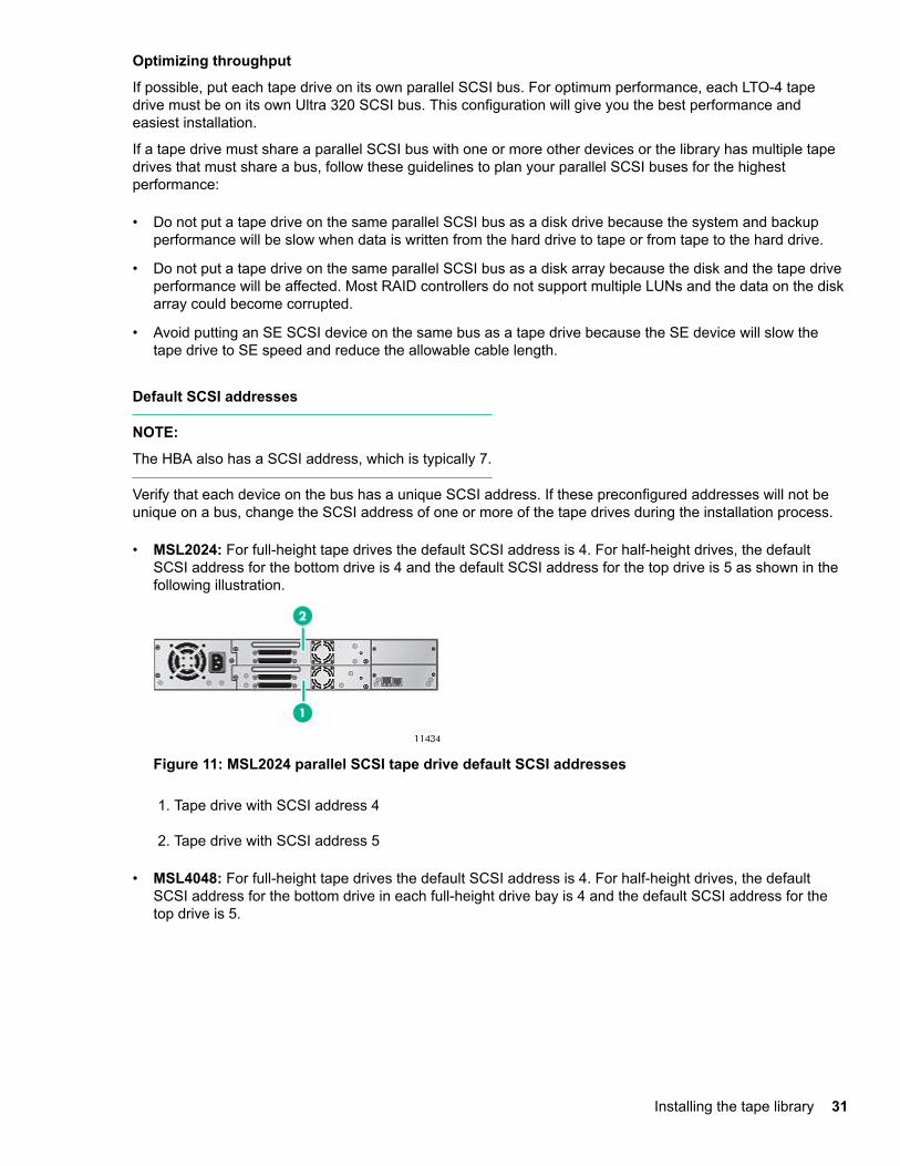
• MSL2024: For full-height tape drives the default SCSI address is 4. For half-height drives, the defaultSCSI address for the bottom drive is 4 and the default SCSI address for the top drive is 5 as shown in thefollowing illustration.
Figure 11: MSL2024 parallel SCSI tape drive default SCSI addresses
1. Tape drive with SCSI address 4
2. Tape drive with SCSI address 5
• MSL4048: For full-height tape drives the default SCSI address is 4. For half-height drives, the defaultSCSI address for the bottom drive in each full-height drive bay is 4 and the default SCSI address for thetop drive is 5.
Installing the tape library 31
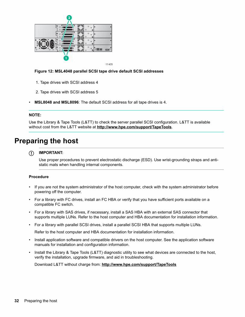
Figure 12: MSL4048 parallel SCSI tape drive default SCSI addresses
1. Tape drives with SCSI address 4
2. Tape drives with SCSI address 5
• MSL8048 and MSL8096: The default SCSI address for all tape drives is 4.
NOTE:
Use the Library & Tape Tools (L&TT) to check the server parallel SCSI configuration. L&TT is availablewithout cost from the L&TT website at http://www.hpe.com/support/TapeTools.
Preparing the hostIMPORTANT:
Use proper procedures to prevent electrostatic discharge (ESD). Use wrist-grounding straps and anti-static mats when handling internal components.
Procedure
• If you are not the system administrator of the host computer, check with the system administrator beforepowering off the computer.
• For a library with FC drives, install an FC HBA or verify that you have sufficient ports available on acompatible FC switch.
• For a library with SAS drives, if necessary, install a SAS HBA with an external SAS connector thatsupports multiple LUNs. Refer to the host computer and HBA documentation for installation information.
• For a library with parallel SCSI drives, install a parallel SCSI HBA that supports multiple LUNs.
Refer to the host computer and HBA documentation for installation information.
• Install application software and compatible drivers on the host computer. See the application softwaremanuals for installation and configuration information.
• Install the Library & Tape Tools (L&TT) diagnostic utility to see what devices are connected to the host,verify the installation, upgrade firmware, and aid in troubleshooting.
Download L&TT without charge from: http://www.hpe.com/support/TapeTools
32 Preparing the host
Unpacking the shipping containerCAUTION:
If the temperature in the room where the library will be installed varies 15ºC (30ºF) from the room whereit was stored, allow library to acclimate to the surrounding environment for at least 12 hours beforeunpacking the shipping container.
Procedure
1. Clear a level work surface near where you will place the library.
2. Inspect the container for shipping damage. If you notice any damage, report it to the shipping companyimmediately.
3. Remove the packaging, accessories, and library from the box one layer at a time.
4. Place the library on a level work surface.
CAUTION:
Do not place the library on either end or its sides as doing so might damage it.
5. Carefully remove the foam padding and then the bag from the library.
6. Save the packaging materials for moving or shipping the library in the future.
7. Verify that you received the following components:
a. Library
b. Ethernet cable
c. Two rack rails with packets of rack hardware
8. Verify that you have the necessary cables.
a. For a library with FC drives, you must provide an FC cable for each FC port you plan to use. See FCconnection information on page 27.
b. For a library with SAS drives, you must provide a SAS cable with the correct connector for your HBA.See SAS connection information on page 28.
Removing the shipping lockSkip this step for the MSL8048 and MSL8096.
The shipping lock prevents the robotic transport mechanism from moving during shipment. Remove theshipping lock before powering on the library. The shipping lock is held in place with a piece of tape and islocated in the top center of the library. After removing the shipping lock, store it on the back panel of thelibrary for future use.
Procedure
1. Locate the tape and shipping lock at the top of the library.
Unpacking the shipping container 33
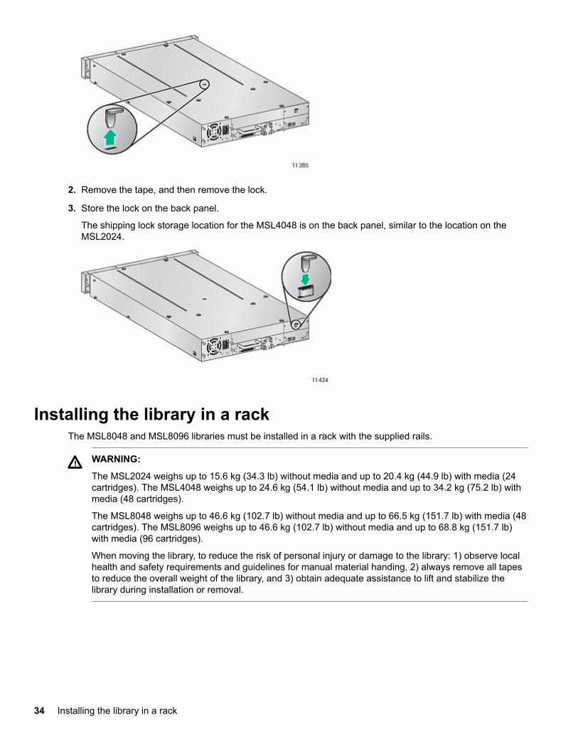
2. Remove the tape, and then remove the lock.
3. Store the lock on the back panel.
The shipping lock storage location for the MSL4048 is on the back panel, similar to the location on theMSL2024.
Installing the library in a rackThe MSL8048 and MSL8096 libraries must be installed in a rack with the supplied rails.
WARNING:
The MSL2024 weighs up to 15.6 kg (34.3 lb) without media and up to 20.4 kg (44.9 lb) with media (24cartridges). The MSL4048 weighs up to 24.6 kg (54.1 lb) without media and up to 34.2 kg (75.2 lb) withmedia (48 cartridges).
The MSL8048 weighs up to 46.6 kg (102.7 lb) without media and up to 66.5 kg (151.7 lb) with media (48cartridges). The MSL8096 weighs up to 46.6 kg (102.7 lb) without media and up to 68.8 kg (151.7 lb)with media (96 cartridges).
When moving the library, to reduce the risk of personal injury or damage to the library: 1) observe localhealth and safety requirements and guidelines for manual material handing, 2) always remove all tapesto reduce the overall weight of the library, and 3) obtain adequate assistance to lift and stabilize thelibrary during installation or removal.
34 Installing the library in a rack
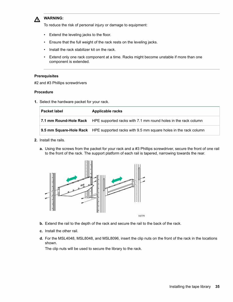
WARNING:
To reduce the risk of personal injury or damage to equipment:
• Extend the leveling jacks to the floor.
• Ensure that the full weight of the rack rests on the leveling jacks.
• Install the rack stabilizer kit on the rack.
• Extend only one rack component at a time. Racks might become unstable if more than onecomponent is extended.
Prerequisites
#2 and #3 Phillips screwdrivers
Procedure
1. Select the hardware packet for your rack.
Packet label Applicable racks
7.1 mm Round-Hole Rack HPE supported racks with 7.1 mm round holes in the rack column
9.5 mm Square-Hole Rack HPE supported racks with 9.5 mm square holes in the rack column
2. Install the rails.
a. Using the screws from the packet for your rack and a #3 Phillips screwdriver, secure the front of one railto the front of the rack. The support platform of each rail is tapered, narrowing towards the rear.
b. Extend the rail to the depth of the rack and secure the rail to the back of the rack.
c. Install the other rail.
d. For the MSL4048, MSL8048, and MSL8096, insert the clip nuts on the front of the rack in the locationsshown.The clip nuts will be used to secure the library to the rack.
Installing the tape library 35
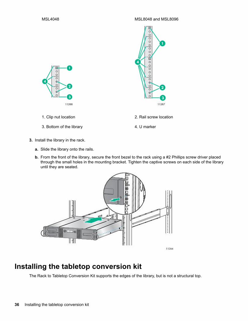
MSL4048 MSL8048 and MSL8096
1. Clip nut location 2. Rail screw location
3. Bottom of the library 4. U marker
3. Install the library in the rack.
a. Slide the library onto the rails.
b. From the front of the library, secure the front bezel to the rack using a #2 Phillips screw driver placedthrough the small holes in the mounting bracket. Tighten the captive screws on each side of the libraryuntil they are seated.
Installing the tabletop conversion kitThe Rack to Tabletop Conversion Kit supports the edges of the library, but is not a structural top.
36 Installing the tabletop conversion kit
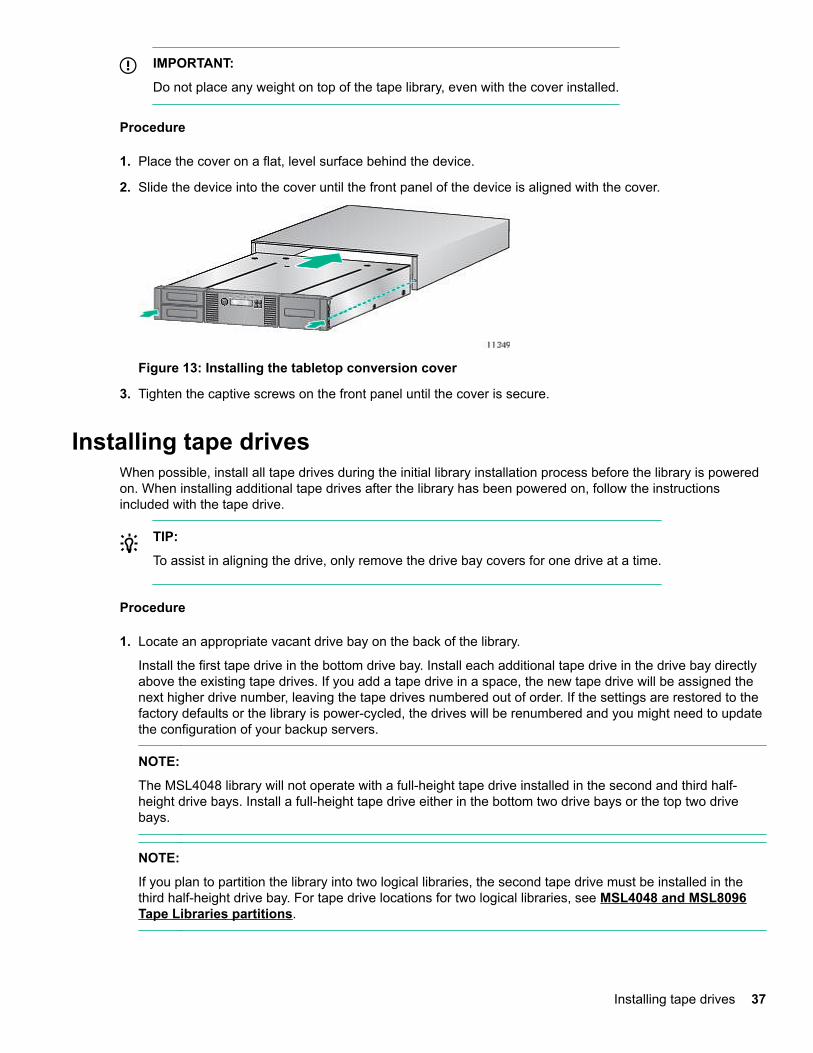
IMPORTANT:
Do not place any weight on top of the tape library, even with the cover installed.
Procedure
1. Place the cover on a flat, level surface behind the device.
2. Slide the device into the cover until the front panel of the device is aligned with the cover.
Figure 13: Installing the tabletop conversion cover
3. Tighten the captive screws on the front panel until the cover is secure.
Installing tape drivesWhen possible, install all tape drives during the initial library installation process before the library is poweredon. When installing additional tape drives after the library has been powered on, follow the instructionsincluded with the tape drive.
TIP:
To assist in aligning the drive, only remove the drive bay covers for one drive at a time.
Procedure
1. Locate an appropriate vacant drive bay on the back of the library.
Install the first tape drive in the bottom drive bay. Install each additional tape drive in the drive bay directlyabove the existing tape drives. If you add a tape drive in a space, the new tape drive will be assigned thenext higher drive number, leaving the tape drives numbered out of order. If the settings are restored to thefactory defaults or the library is power-cycled, the drives will be renumbered and you might need to updatethe configuration of your backup servers.
NOTE:
The MSL4048 library will not operate with a full-height tape drive installed in the second and third half-height drive bays. Install a full-height tape drive either in the bottom two drive bays or the top two drivebays.
NOTE:
If you plan to partition the library into two logical libraries, the second tape drive must be installed in thethird half-height drive bay. For tape drive locations for two logical libraries, see MSL4048 and MSL8096Tape Libraries partitions.
Installing tape drives 37
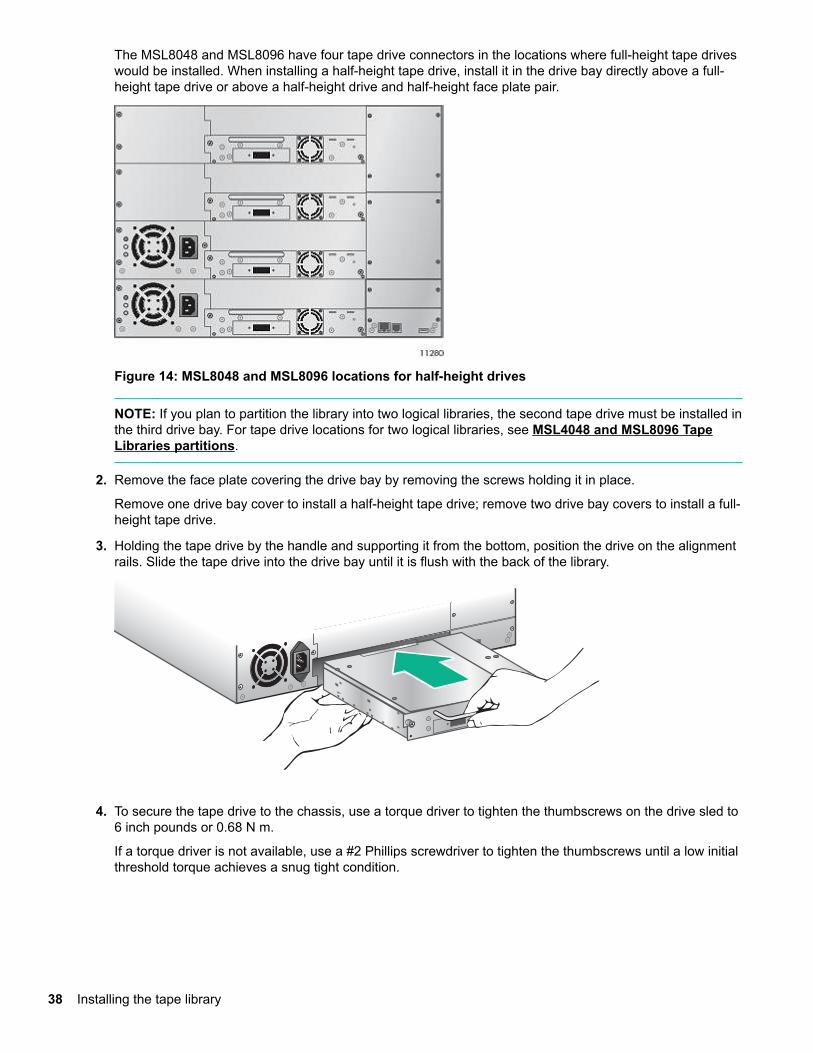
The MSL8048 and MSL8096 have four tape drive connectors in the locations where full-height tape driveswould be installed. When installing a half-height tape drive, install it in the drive bay directly above a full-height tape drive or above a half-height drive and half-height face plate pair.
Figure 14: MSL8048 and MSL8096 locations for half-height drives
NOTE: If you plan to partition the library into two logical libraries, the second tape drive must be installed inthe third drive bay. For tape drive locations for two logical libraries, see MSL4048 and MSL8096 TapeLibraries partitions.
2. Remove the face plate covering the drive bay by removing the screws holding it in place.
Remove one drive bay cover to install a half-height tape drive; remove two drive bay covers to install a full-height tape drive.
3. Holding the tape drive by the handle and supporting it from the bottom, position the drive on the alignmentrails. Slide the tape drive into the drive bay until it is flush with the back of the library.
4. To secure the tape drive to the chassis, use a torque driver to tighten the thumbscrews on the drive sled to6 inch pounds or 0.68 N m.
If a torque driver is not available, use a #2 Phillips screwdriver to tighten the thumbscrews until a low initialthreshold torque achieves a snug tight condition.
38 Installing the tape library
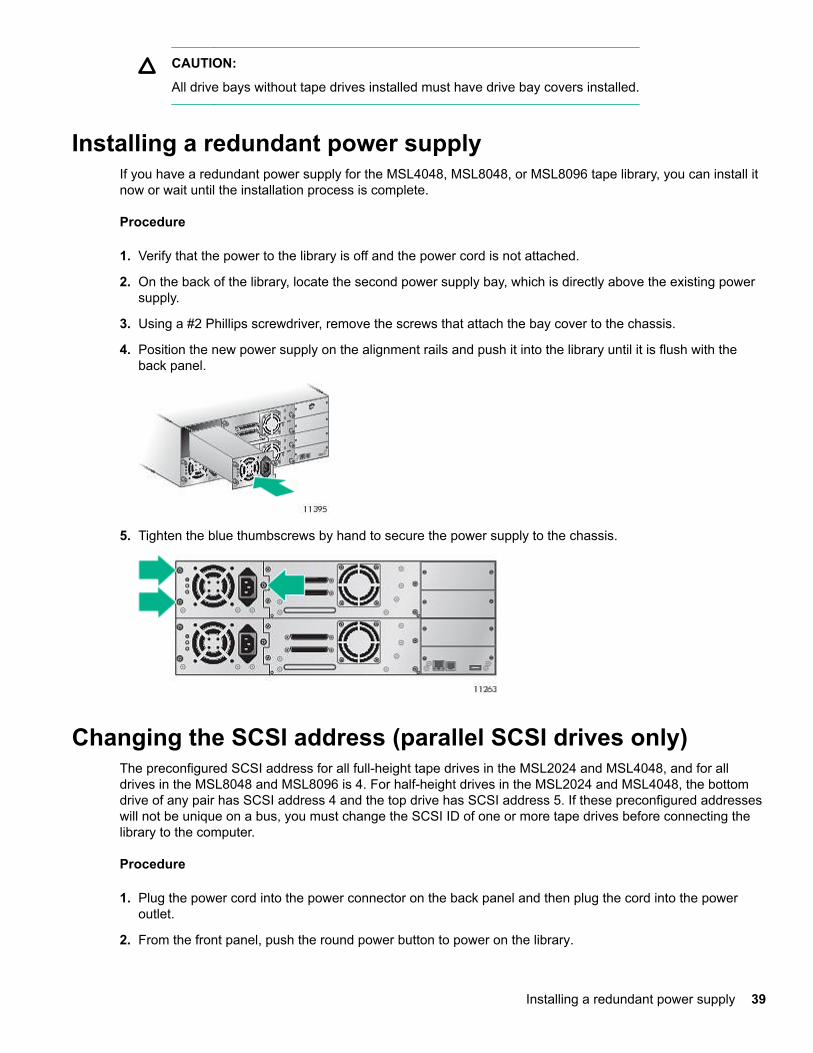
CAUTION:
All drive bays without tape drives installed must have drive bay covers installed.
Installing a redundant power supplyIf you have a redundant power supply for the MSL4048, MSL8048, or MSL8096 tape library, you can install itnow or wait until the installation process is complete.
Procedure
1. Verify that the power to the library is off and the power cord is not attached.
2. On the back of the library, locate the second power supply bay, which is directly above the existing powersupply.
3. Using a #2 Phillips screwdriver, remove the screws that attach the bay cover to the chassis.
4. Position the new power supply on the alignment rails and push it into the library until it is flush with theback panel.
5. Tighten the blue thumbscrews by hand to secure the power supply to the chassis.
Changing the SCSI address (parallel SCSI drives only)The preconfigured SCSI address for all full-height tape drives in the MSL2024 and MSL4048, and for alldrives in the MSL8048 and MSL8096 is 4. For half-height drives in the MSL2024 and MSL4048, the bottomdrive of any pair has SCSI address 4 and the top drive has SCSI address 5. If these preconfigured addresseswill not be unique on a bus, you must change the SCSI ID of one or more tape drives before connecting thelibrary to the computer.
Procedure
1. Plug the power cord into the power connector on the back panel and then plug the cord into the poweroutlet.
2. From the front panel, push the round power button to power on the library.
Installing a redundant power supply 39
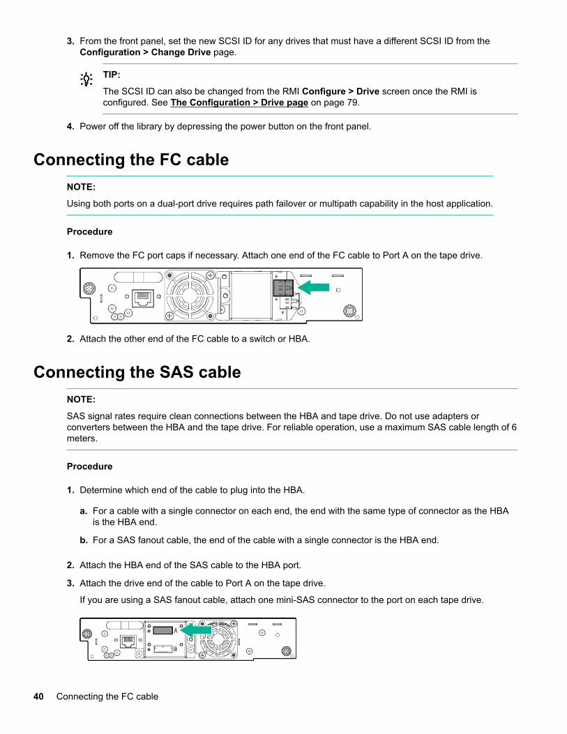
3. From the front panel, set the new SCSI ID for any drives that must have a different SCSI ID from theConfiguration > Change Drive page.
TIP:
The SCSI ID can also be changed from the RMI Configure > Drive screen once the RMI isconfigured. See The Configuration > Drive page on page 79.
4. Power off the library by depressing the power button on the front panel.
Connecting the FC cableNOTE:
Using both ports on a dual-port drive requires path failover or multipath capability in the host application.
Procedure
1. Remove the FC port caps if necessary. Attach one end of the FC cable to Port A on the tape drive.
2. Attach the other end of the FC cable to a switch or HBA.
Connecting the SAS cableNOTE:
SAS signal rates require clean connections between the HBA and tape drive. Do not use adapters orconverters between the HBA and the tape drive. For reliable operation, use a maximum SAS cable length of 6meters.
Procedure
1. Determine which end of the cable to plug into the HBA.
a. For a cable with a single connector on each end, the end with the same type of connector as the HBAis the HBA end.
b. For a SAS fanout cable, the end of the cable with a single connector is the HBA end.
2. Attach the HBA end of the SAS cable to the HBA port.
3. Attach the drive end of the cable to Port A on the tape drive.
If you are using a SAS fanout cable, attach one mini-SAS connector to the port on each tape drive.
40 Connecting the FC cable
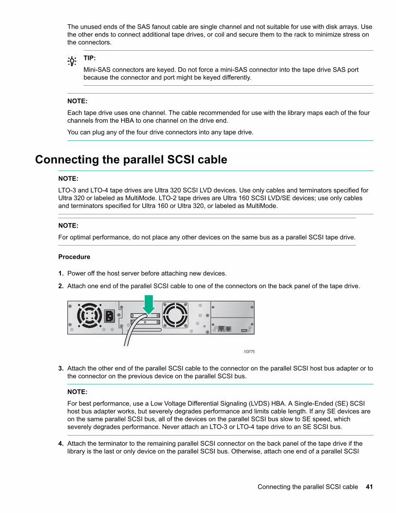
The unused ends of the SAS fanout cable are single channel and not suitable for use with disk arrays. Usethe other ends to connect additional tape drives, or coil and secure them to the rack to minimize stress onthe connectors.
TIP:
Mini-SAS connectors are keyed. Do not force a mini-SAS connector into the tape drive SAS portbecause the connector and port might be keyed differently.
NOTE:
Each tape drive uses one channel. The cable recommended for use with the library maps each of the fourchannels from the HBA to one channel on the drive end.
You can plug any of the four drive connectors into any tape drive.
Connecting the parallel SCSI cableNOTE:
LTO-3 and LTO-4 tape drives are Ultra 320 SCSI LVD devices. Use only cables and terminators specified forUltra 320 or labeled as MultiMode. LTO-2 tape drives are Ultra 160 SCSI LVD/SE devices; use only cablesand terminators specified for Ultra 160 or Ultra 320, or labeled as MultiMode.
NOTE:
For optimal performance, do not place any other devices on the same bus as a parallel SCSI tape drive.
Procedure
1. Power off the host server before attaching new devices.
2. Attach one end of the parallel SCSI cable to one of the connectors on the back panel of the tape drive.
3. Attach the other end of the parallel SCSI cable to the connector on the parallel SCSI host bus adapter or tothe connector on the previous device on the parallel SCSI bus.
NOTE:
For best performance, use a Low Voltage Differential Signaling (LVDS) HBA. A Single-Ended (SE) SCSIhost bus adapter works, but severely degrades performance and limits cable length. If any SE devices areon the same parallel SCSI bus, all of the devices on the parallel SCSI bus slow to SE speed, whichseverely degrades performance. Never attach an LTO-3 or LTO-4 tape drive to an SE SCSI bus.
4. Attach the terminator to the remaining parallel SCSI connector on the back panel of the tape drive if thelibrary is the last or only device on the parallel SCSI bus. Otherwise, attach one end of a parallel SCSI
Connecting the parallel SCSI cable 41
cable to the remaining port and the other end to the next device on the parallel SCSI bus. Make sure thatthe last device on the parallel SCSI bus is properly terminated.
IMPORTANT:
For the library and tape drives to operate correctly, each SCSI tape drive must have a SCSIterminator unless the tape drive is part of a properly terminated chain. A tape drive without anattached SCSI cable must also have a SCSI terminator.
Powering on the libraryWARNING:
To reduce the risk of electric shock or damage to the equipment:
• Use an approved power cord. If you have questions about the type of power cord to use, contactyour authorized service provider.
• Use a power cord rated for your product and for the voltage and current marked on the electricalratings label of the product. The voltage and current rating of the cord must be greater than thevoltage and current rating marked on the product.
Procedure
1. If you plan to use the RMI, use an Ethernet cable to connect the library to a working LAN connection. Thelibrary Ethernet connector is on the back of the library.
2. Attach a power cable to the power connector on each power supply on the back of the library.
3. Plug the power cables into the nearest properly grounded power outlets.
4. Power on the library by pressing the power button on the front panel.
5. To verify that the library has power, check the LCD screen.
If the library does not have power, check the power connections and your power source.
During the Power On Self-Test (POST), all four LEDs are illuminated briefly, followed by a flashing ReadyLED. When the initialization sequence is complete, the Home screen is displayed.
If the inventory takes over five minutes, the splash screen is displayed. To see the Home screen, pressany button.
6. Plug in the host server and all attached devices.
7. Power on any other devices you powered off earlier.
8. Power on the server.
Configuring the libraryProcedure
1. Set the administrator password.
Setting an administrator password provides access to the administrator functions with the RMI or OCP,and restricts access to administrator functions to only those people who know the administrator password.
42 Powering on the library
The library comes with a null administrator password, which until set allows unrestricted access to alladministrative functions through the OCP but not the RMI. Once the administrator password has been setfrom the OCP, it can be changed from either the OCP or RMI.
• For the MSL2024, see Changing the administrator password (Configuration > Change AdminPassword) on page 104.
• For the MSL4048, MSL8048, and MSL8096, see Setting and changing the administrator password(Configuration> Set Admin Password) on page 137.
2. Set the date and time.
The date and time are used by the library to record events. For ease of communication and productsupport, set the date and time during the initial installation process.
• For the MSL2024, see Setting the date and time (Configuration > Library Date/Time) on page 109.
• For the MSL4048, MSL8048, and MSL8096, see Setting the library date and time (Configuration >Set Date and Time) on page 139.
3. If necessary, configure the FC interface.
Recommended FC interface configuration
4. Configure the library network settings.
Configuring the library network settings enables you to monitor, configure, and control most libraryfunctions from the RMI. By default, the device will obtain an IP address from an IPv4 DHCP server.Optionally, you can configure the device to use a static IP address. Once logged in to the RMI, you canadminister further network changes through the RMI.
• For the MSL2024, see Configuring IPv4 network settings (Configuration > Configure NetworkSettings) on page 110.
• For the MSL4048, MSL8048, and MSL8096, see Changing the network configuration(Configuration > Network) on page 137.
5. The device supports IPv4 and IPv6 Internet Protocols. By default, the device is configured to use IPv4, themost common version. You can enable IPv6 or both Internet Protocols from the OCP or RMI. Use the RMIto finish configuring IPv6. (See The Configuration > Network page on page 81.)
Recommended FC interface configurationDrives connected to a SAN
Leave the FC port at the default settings of Port Speed: Automatic and Port Type: Auto Detect. With thesesettings, the tape drive will use the appropriate configuration.
Drives connected directly to the host
• For LTO-7 and later drives, use Loop mode.
• For LTO-6 and earlier drives, leave the FC port at the default settings of Port Speed: Automatic and PortType: Auto Detect. With these settings, the tape drive will use the appropriate configuration.
Use the Configuration > Drives screen to change the settings.
Recommended FC interface configuration 43

Verifying the connectionProcedure
1. Install the application software and/or drivers that are compatible with the library.
Backup software packages might require additional software or licensing to communicate with the robotics.
For software compatibility information, see the Data Agile BURA Compatibility Matrix at: http://www.hpe.com/storage/buracompatibility
2. Verify the connection between the library and the host:
a. Install the Library & Tape Tools Diagnostic/Installation Check Utility onto the host computer.
This utility verifies that the unit is connected and communicating with the host server. It also verifies thatthe device is functioning and provides diagnostic information. To verify your connections, run theLibrary & Tape Tools Installation Check from the programs menu.
L&TT is available without cost at:http://www.hpe.com/support/TapeTools
b. Confirm that the host server operating system recognizes the library.
In Windows, look for tape drives and media changers in the Device Manager.
For more information on verifying the connection of parallel SCSI devices, consult the operating systemdocumentation.
Labeling the tape cartridgesThe library will operate without barcode labels on the cartridges. Using barcode labels in productionenvironments improves inventory time in the library and eases cartridge handling processes outside thelibrary.
Attaching a bar code label to each tape cartridge enables the library and application software to identify thecartridge quickly, which speeds up inventory time. Make using bar code labels on your tapes a practice.
IMPORTANT:
Misusing and misunderstanding bar code technology can result in backup and restore failures. Toensure that your bar code labels meet Hewlett Packard Enterprise quality standards, always purchasethem from an approved supplier and never print bar code labels yourself.
Prerequisites
High-quality preprinted barcode labels with the correct Media ID.
Procedure
Apply a high-quality preprinted bar code label to each tape cartridge.
LTO tape cartridges have a recessed area on the face of the cartridge next to the write-protect switch. Usethis area for attaching the adhesive-backed bar code label.
44 Verifying the connection
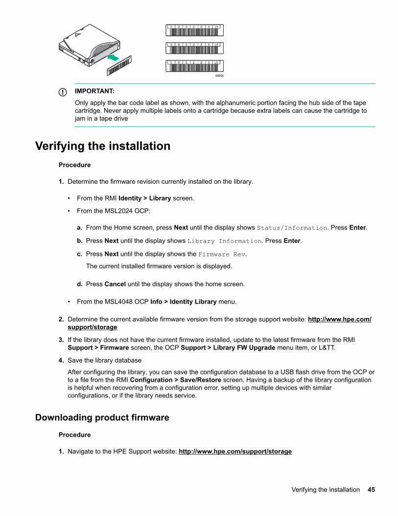
IMPORTANT:
Only apply the bar code label as shown, with the alphanumeric portion facing the hub side of the tapecartridge. Never apply multiple labels onto a cartridge because extra labels can cause the cartridge tojam in a tape drive
Verifying the installationProcedure
1. Determine the firmware revision currently installed on the library.
• From the RMI Identity > Library screen.
• From the MSL2024 OCP:
a. From the Home screen, press Next until the display shows Status/Information. Press Enter.
b. Press Next until the display shows Library Information. Press Enter.
c. Press Next until the display shows the Firmware Rev.
The current installed firmware version is displayed.
d. Press Cancel until the display shows the home screen.
• From the MSL4048 OCP Info > Identity Library menu.
2. Determine the current available firmware version from the storage support website: http://www.hpe.com/support/storage
3. If the library does not have the current firmware installed, update to the latest firmware from the RMISupport > Firmware screen, the OCP Support > Library FW Upgrade menu item, or L&TT.
4. Save the library database
After configuring the library, you can save the configuration database to a USB flash drive from the OCP orto a file from the RMI Configuration > Save/Restore screen. Having a backup of the library configurationis helpful when recovering from a configuration error, setting up multiple devices with similarconfigurations, or if the library needs service.
Downloading product firmware
Procedure
1. Navigate to the HPE Support website: http://www.hpe.com/support/storage
Verifying the installation 45
IMPORTANT:
Access to some updates might require product entitlement when accessed through the HewlettPackard Enterprise Support Center. You must have an HPE Passport set up with relevantentitlements.
To view and update your entitlements, and to link your contracts and warranties with your profile,navigate to: http://www.hpe.com/support/AccessToSupportMaterials
2. Browse or search for the necessary firmware.
3. Download the firmware.
To upgrade firmware from the OCP, copy the firmware image onto a FAT-32 formatted USB flash drive.
Configuring additional featuresThe tape library has many features to customize it for your organization.
Procedure
1. Naming the tape library, which is done from the RMI Configuration > Network screen. See TheConfiguration > Network page on page 81.
2. Partitioning a library with multiple tape drives into logical libraries. See The Configuration > System pageon page 73.
3. Enabling and configuring SNMP network management or Command View TL TapeAssure. See TheConfiguration > Network Management page on page 83.
4. Setting up email event notification. See The Configuration > Alerts page on page 87.
5. To use the RMI and OCP in Japanese, enable the Japanese language option through the RMI. See TheConfiguration > System page on page 73.
46 Configuring additional features
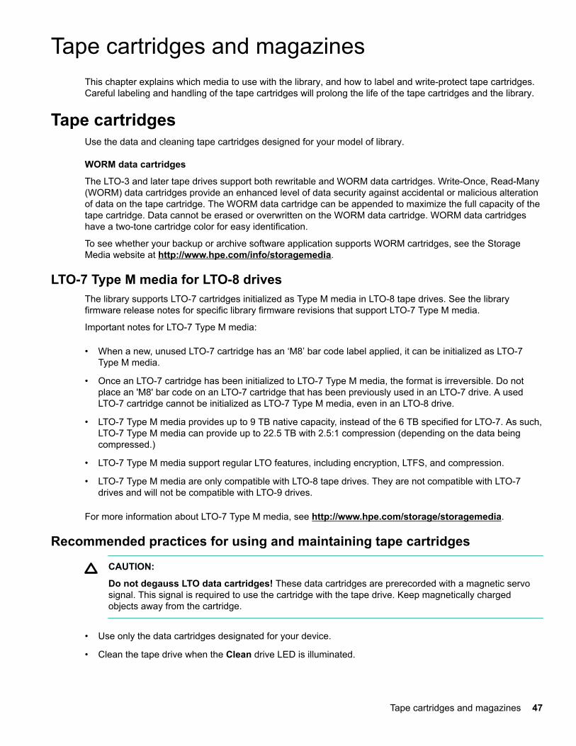
Tape cartridges and magazinesThis chapter explains which media to use with the library, and how to label and write-protect tape cartridges.Careful labeling and handling of the tape cartridges will prolong the life of the tape cartridges and the library.
Tape cartridgesUse the data and cleaning tape cartridges designed for your model of library.
WORM data cartridges
The LTO-3 and later tape drives support both rewritable and WORM data cartridges. Write-Once, Read-Many(WORM) data cartridges provide an enhanced level of data security against accidental or malicious alterationof data on the tape cartridge. The WORM data cartridge can be appended to maximize the full capacity of thetape cartridge. Data cannot be erased or overwritten on the WORM data cartridge. WORM data cartridgeshave a two-tone cartridge color for easy identification.
To see whether your backup or archive software application supports WORM cartridges, see the StorageMedia website at http://www.hpe.com/info/storagemedia.
LTO-7 Type M media for LTO-8 drivesThe library supports LTO-7 cartridges initialized as Type M media in LTO-8 tape drives. See the libraryfirmware release notes for specific library firmware revisions that support LTO-7 Type M media.
Important notes for LTO-7 Type M media:
• When a new, unused LTO-7 cartridge has an ‘M8’ bar code label applied, it can be initialized as LTO-7Type M media.
• Once an LTO-7 cartridge has been initialized to LTO-7 Type M media, the format is irreversible. Do notplace an 'M8' bar code on an LTO-7 cartridge that has been previously used in an LTO-7 drive. A usedLTO-7 cartridge cannot be initialized as LTO-7 Type M media, even in an LTO-8 drive.
• LTO-7 Type M media provides up to 9 TB native capacity, instead of the 6 TB specified for LTO-7. As such,LTO-7 Type M media can provide up to 22.5 TB with 2.5:1 compression (depending on the data beingcompressed.)
• LTO-7 Type M media support regular LTO features, including encryption, LTFS, and compression.
• LTO-7 Type M media are only compatible with LTO-8 tape drives. They are not compatible with LTO-7drives and will not be compatible with LTO-9 drives.
For more information about LTO-7 Type M media, see http://www.hpe.com/storage/storagemedia.
Recommended practices for using and maintaining tape cartridges
CAUTION:
Do not degauss LTO data cartridges! These data cartridges are prerecorded with a magnetic servosignal. This signal is required to use the cartridge with the tape drive. Keep magnetically chargedobjects away from the cartridge.
• Use only the data cartridges designated for your device.
• Clean the tape drive when the Clean drive LED is illuminated.
Tape cartridges and magazines 47
CAUTION:
Use only Ultrium Universal Cleaning Cartridges (UCC).
• Do not drop a cartridge. Excessive shock can damage the internal contents of the cartridge or thecartridge case itself, making the cartridge unusable.
• Do not expose data cartridges to direct sunlight or sources of heat, including portable heaters and heatingducts.
• The operating temperature range for data cartridges is 10 to 35º C. The storage temperature range is 16 to32º C in a dust-free environment with relative humidity always between 20 percent and 80 percent(noncondensing).
• If the data cartridge has been exposed to temperatures outside the specified ranges, stabilize the cartridgeat room temperature for the same length of time it was exposed to extreme temperatures or 24 hours,whichever is less.
• Do not place data cartridges near sources of electromagnetic energy or strong magnetic fields such ascomputer monitors, electric motors, speakers, or X-ray equipment. Exposure to electromagnetic energy ormagnetic fields can destroy data and the embedded servo code written on the media by the cartridgemanufacturer. The cartridge is unusable without the embedded servo code.
• Place identification labels only in the designated area on the cartridge.
Recommended practices for labeling tape cartridgesThe library contains a bar code reader that reads the tape labels and stores the inventory data in memory.The device then provides the inventory information to the host application, OCP, and RMI. A bar code label oneach tape cartridge enables the bar code reader to identify the cartridge quickly, which speeds up inventorytime. Make using bar code labels on your tape cartridges a practice.
TIP:
The bar code scanner scans each tape or the back of the storage slot until it reads the bar code label forthe cartridge or storage slot, or determines that the slot is empty. The bar code scanner can identify aproperly labeled cartridge on the first scan. It can identify an empty slot on the second scan. It will tryseveral more scans and then tap on the cartridge before determining that an unlabeled cartridge is inthe slot, which takes about four times as long as identifying a properly labeled cartridge.
The inventory time for an MSL8048 or MSL8096 filled with unlabeled cartridges is about 30 minutes.Even if you do not need the bar code information, use bar code labels to speed up inventory time.
A proper bar code label includes the Media ID in the last two characters of the bar code. LTO-3 and earliergeneration tape drives prevent later generation media from being loaded into the drive. If an LTO-4 or latertape drive is installed in the library or is in the removed state, the library will not load an unlabeled cartridgeinto an LTO-3 or earlier generation tape drive.
Though not recommended, checking Ignore Barcode Media ID in the RMI Configuration > System screenwill keep the library from interpreting bar code Media IDs.
The host software might track the following information through the associated bar code:
• Date of format or initialization
• Tape cartridge media pool
• Data residing on the tape
48 Recommended practices for labeling tape cartridges
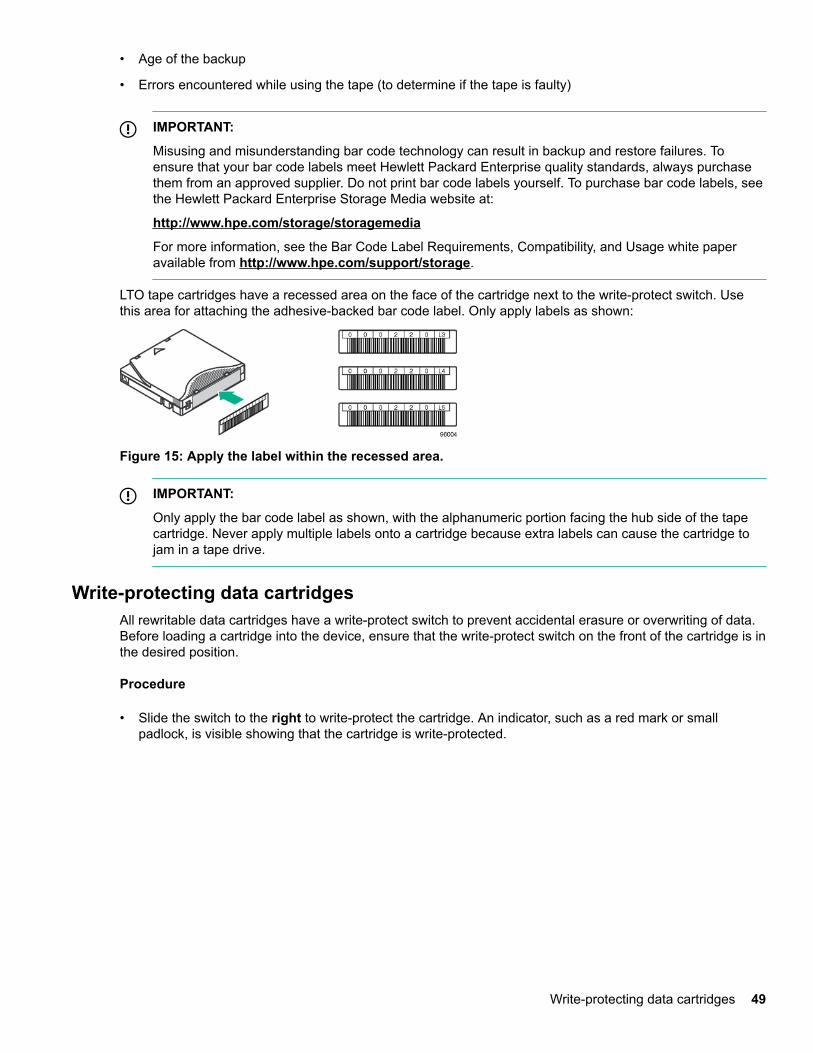
• Age of the backup
• Errors encountered while using the tape (to determine if the tape is faulty)
IMPORTANT:
Misusing and misunderstanding bar code technology can result in backup and restore failures. Toensure that your bar code labels meet Hewlett Packard Enterprise quality standards, always purchasethem from an approved supplier. Do not print bar code labels yourself. To purchase bar code labels, seethe Hewlett Packard Enterprise Storage Media website at:
http://www.hpe.com/storage/storagemedia
For more information, see the Bar Code Label Requirements, Compatibility, and Usage white paperavailable from http://www.hpe.com/support/storage.
LTO tape cartridges have a recessed area on the face of the cartridge next to the write-protect switch. Usethis area for attaching the adhesive-backed bar code label. Only apply labels as shown:
Figure 15: Apply the label within the recessed area.
IMPORTANT:
Only apply the bar code label as shown, with the alphanumeric portion facing the hub side of the tapecartridge. Never apply multiple labels onto a cartridge because extra labels can cause the cartridge tojam in a tape drive.
Write-protecting data cartridgesAll rewritable data cartridges have a write-protect switch to prevent accidental erasure or overwriting of data.Before loading a cartridge into the device, ensure that the write-protect switch on the front of the cartridge is inthe desired position.
Procedure
• Slide the switch to the right to write-protect the cartridge. An indicator, such as a red mark or smallpadlock, is visible showing that the cartridge is write-protected.
Write-protecting data cartridges 49
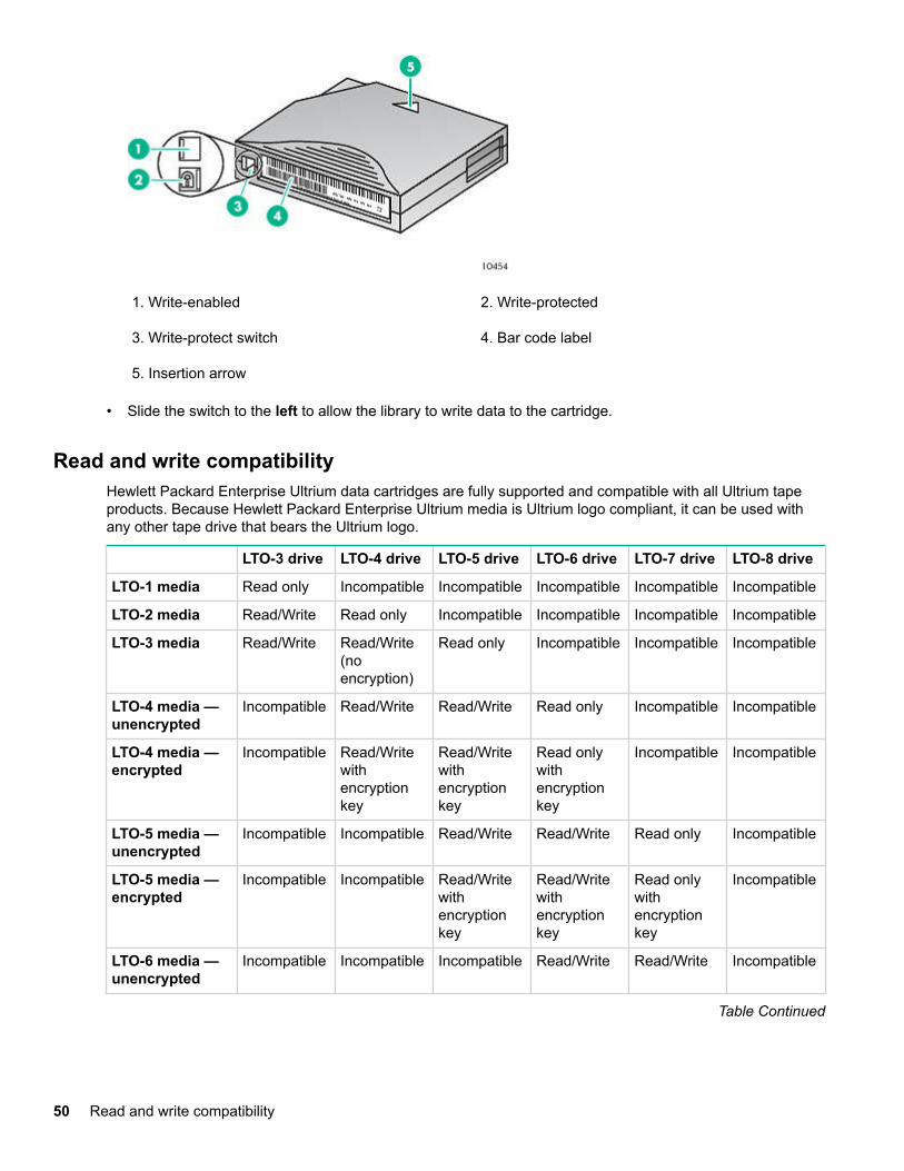
1. Write-enabled 2. Write-protected
3. Write-protect switch 4. Bar code label
5. Insertion arrow
• Slide the switch to the left to allow the library to write data to the cartridge.
Read and write compatibilityHewlett Packard Enterprise Ultrium data cartridges are fully supported and compatible with all Ultrium tapeproducts. Because Hewlett Packard Enterprise Ultrium media is Ultrium logo compliant, it can be used withany other tape drive that bears the Ultrium logo.
LTO-3 drive LTO-4 drive LTO-5 drive LTO-6 drive LTO-7 drive LTO-8 drive
LTO-1 media Read only Incompatible Incompatible Incompatible Incompatible Incompatible
LTO-2 media Read/Write Read only Incompatible Incompatible Incompatible Incompatible
LTO-3 media Read/Write Read/Write(noencryption)
Read only Incompatible Incompatible Incompatible
LTO-4 media —unencrypted
Incompatible Read/Write Read/Write Read only Incompatible Incompatible
LTO-4 media —encrypted
Incompatible Read/Writewithencryptionkey
Read/Writewithencryptionkey
Read onlywithencryptionkey
Incompatible Incompatible
LTO-5 media —unencrypted
Incompatible Incompatible Read/Write Read/Write Read only Incompatible
LTO-5 media —encrypted
Incompatible Incompatible Read/Writewithencryptionkey
Read/Writewithencryptionkey
Read onlywithencryptionkey
Incompatible
LTO-6 media —unencrypted
Incompatible Incompatible Incompatible Read/Write Read/Write Incompatible
Table Continued
50 Read and write compatibility
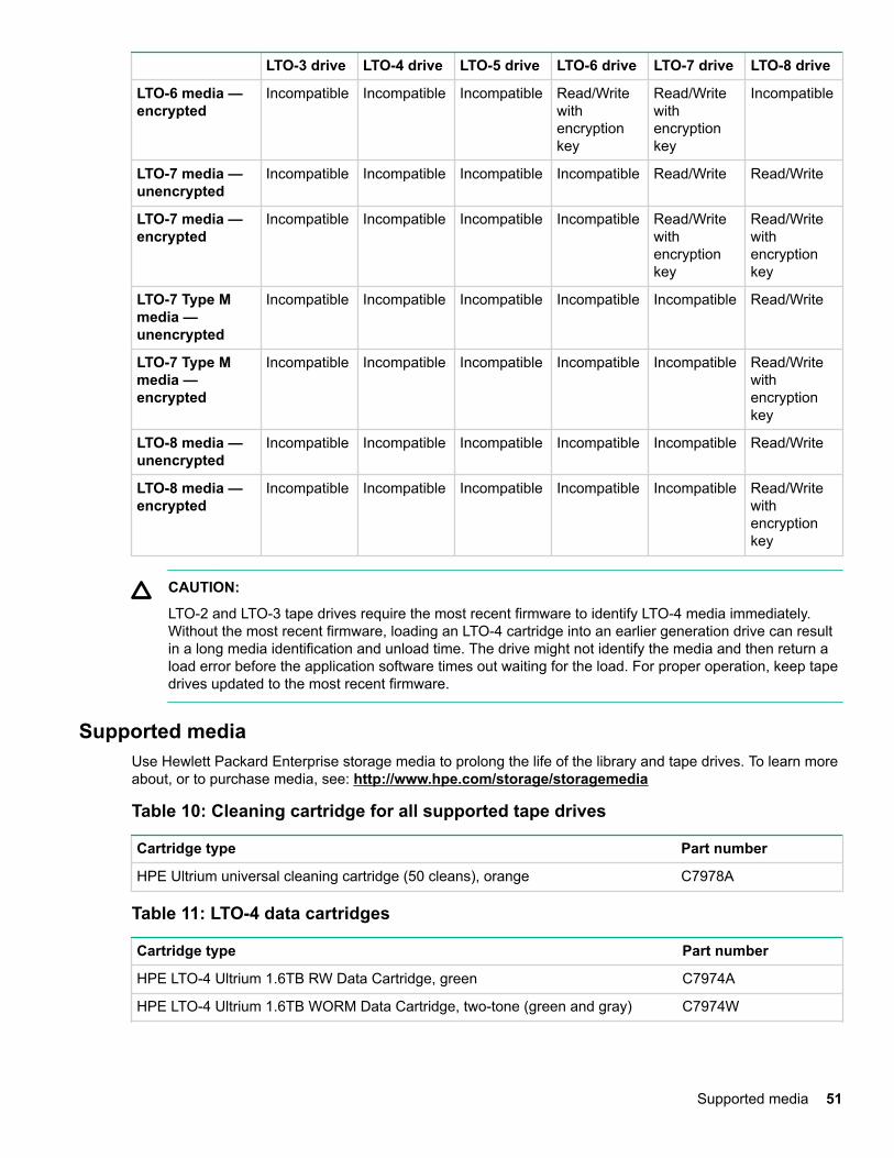
LTO-3 drive LTO-4 drive LTO-5 drive LTO-6 drive LTO-7 drive LTO-8 drive
LTO-6 media —encrypted
Incompatible Incompatible Incompatible Read/Writewithencryptionkey
Read/Writewithencryptionkey
Incompatible
LTO-7 media —unencrypted
Incompatible Incompatible Incompatible Incompatible Read/Write Read/Write
LTO-7 media —encrypted
Incompatible Incompatible Incompatible Incompatible Read/Writewithencryptionkey
Read/Writewithencryptionkey
LTO-7 Type Mmedia —unencrypted
Incompatible Incompatible Incompatible Incompatible Incompatible Read/Write
LTO-7 Type Mmedia —encrypted
Incompatible Incompatible Incompatible Incompatible Incompatible Read/Writewithencryptionkey
LTO-8 media —unencrypted
Incompatible Incompatible Incompatible Incompatible Incompatible Read/Write
LTO-8 media —encrypted
Incompatible Incompatible Incompatible Incompatible Incompatible Read/Writewithencryptionkey
CAUTION:
LTO-2 and LTO-3 tape drives require the most recent firmware to identify LTO-4 media immediately.Without the most recent firmware, loading an LTO-4 cartridge into an earlier generation drive can resultin a long media identification and unload time. The drive might not identify the media and then return aload error before the application software times out waiting for the load. For proper operation, keep tapedrives updated to the most recent firmware.
Supported mediaUse Hewlett Packard Enterprise storage media to prolong the life of the library and tape drives. To learn moreabout, or to purchase media, see: http://www.hpe.com/storage/storagemedia
Table 10: Cleaning cartridge for all supported tape drives
Cartridge type Part number
HPE Ultrium universal cleaning cartridge (50 cleans), orange C7978A
Table 11: LTO-4 data cartridges
Cartridge type Part number
HPE LTO-4 Ultrium 1.6TB RW Data Cartridge, green C7974A
HPE LTO-4 Ultrium 1.6TB WORM Data Cartridge, two-tone (green and gray) C7974W
Supported media 51
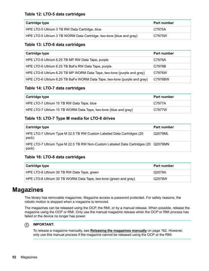
Table 12: LTO-5 data cartridges
Cartridge type Part number
HPE LTO-5 Ultrium 3 TB RW Data Cartridge, blue C7975A
HPE LTO-5 Ultrium 3 TB WORM Data Cartridge, two-tone (blue and gray) C7975W
Table 13: LTO-6 data cartridges
Cartridge type Part number
HPE LTO-6 Ultrium 6.25 TB MP RW Data Tape, purple C7976A
HPE LTO-6 Ultrium 6.25 TB BaFe RW Data Tape, purple C7976B
HPE LTO-6 Ultrium 6.25 TB MP WORM Data Tape, two-tone (purple and gray) C7976W
HPE LTO-6 Ultrium 6.25 TB BaFe WORM Data Tape, two-tone (purple and gray) C7976BW
Table 14: LTO-7 data cartridges
Cartridge type Part number
HPE LTO-7 Ultrium 15 TB RW Data Tape, blue C7977A
HPE LTO-7 Ultrium 15 TB WORM Data Tape, two-tone (blue and gray) C7977W
Table 15: LTO-7 Type M media for LTO-8 drives
Cartridge type Part number
HPE LTO-7 Ultrium Type M 22.5 TB RW Custom Labeled Data Cartridges (20pack)
Q2078ML
HPE LTO-7 Ultrium Type M 22.5 TB RW Non-Custom Labeled Data Cartridges (20pack)
Q2078MN
Table 16: LTO-8 data cartridges
Cartridge type Part number
HPE LTO-8 Ultrium 30 TB RW Data Tape, green Q2078A
HPE LTO-8 Ultrium 30 TB WORM Data Tape, two-tone (green and gray) Q2078W
MagazinesThe library has removable magazines. Magazine access is password protected. For safety reasons, therobotic motion is stopped when a magazine is removed.
The magazines can be released using the OCP, the RMI, or by a manual release. When possible, release themagazine using the OCP or RMI. Only use the manual magazine release when the OCP or RMI process hasfailed or the device no longer has power.
IMPORTANT:
To release a magazine manually, see Releasing the magazines manually on page 162. However,only use this manual process if the magazine cannot be released using the OCP or the RMI.
52 Magazines
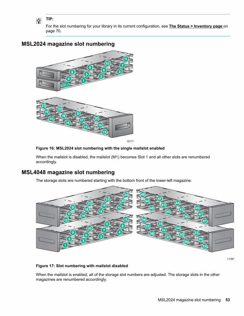
TIP:
For the slot numbering for your library in its current configuration, see The Status > Inventory page onpage 70.
MSL2024 magazine slot numbering
Figure 16: MSL2024 slot numbering with the single mailslot enabled
When the mailslot is disabled, the mailslot (M1) becomes Slot 1 and all other slots are renumberedaccordingly.
MSL4048 magazine slot numberingThe storage slots are numbered starting with the bottom front of the lower-left magazine.
Figure 17: Slot numbering with mailslot disabled
When the mailslot is enabled, all of the storage slot numbers are adjusted. The storage slots in the othermagazines are renumbered accordingly.
MSL2024 magazine slot numbering 53
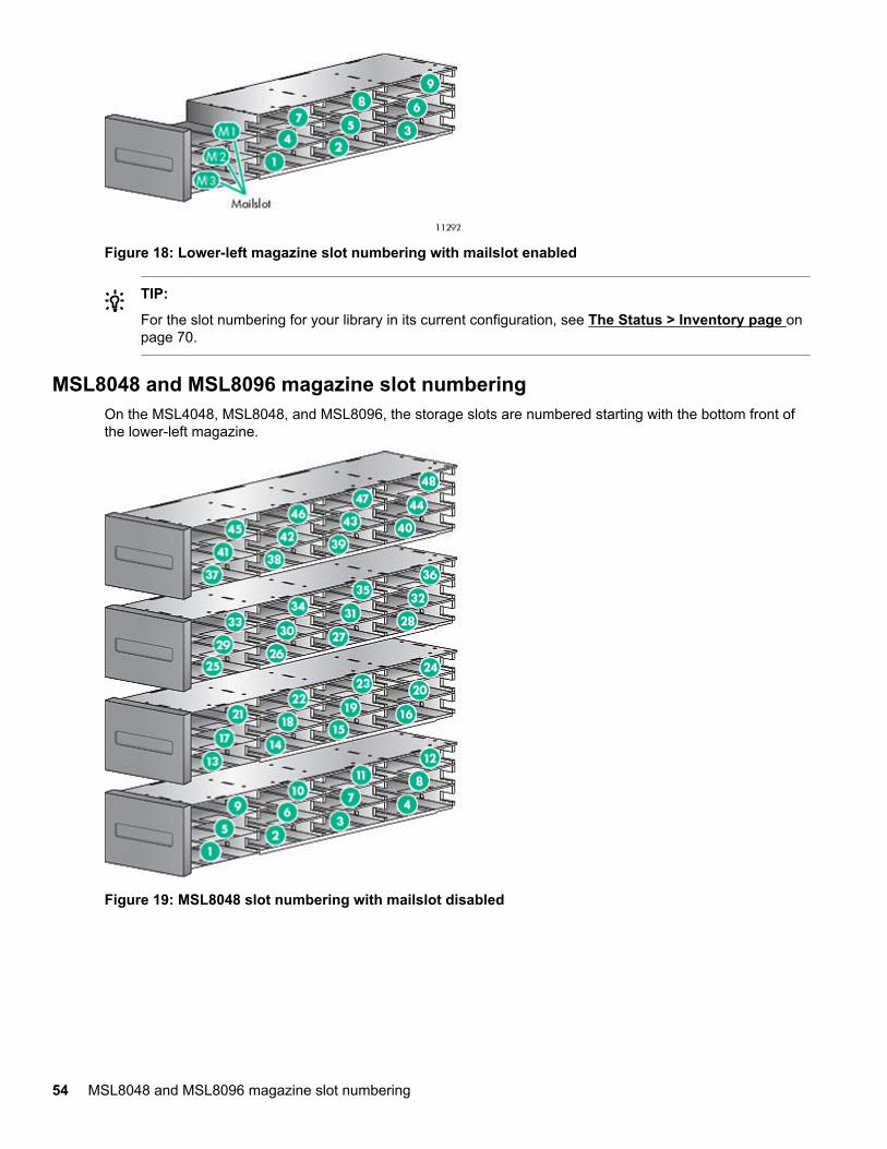
Figure 18: Lower-left magazine slot numbering with mailslot enabled
TIP:
For the slot numbering for your library in its current configuration, see The Status > Inventory page onpage 70.
MSL8048 and MSL8096 magazine slot numberingOn the MSL4048, MSL8048, and MSL8096, the storage slots are numbered starting with the bottom front ofthe lower-left magazine.
Figure 19: MSL8048 slot numbering with mailslot disabled
54 MSL8048 and MSL8096 magazine slot numbering
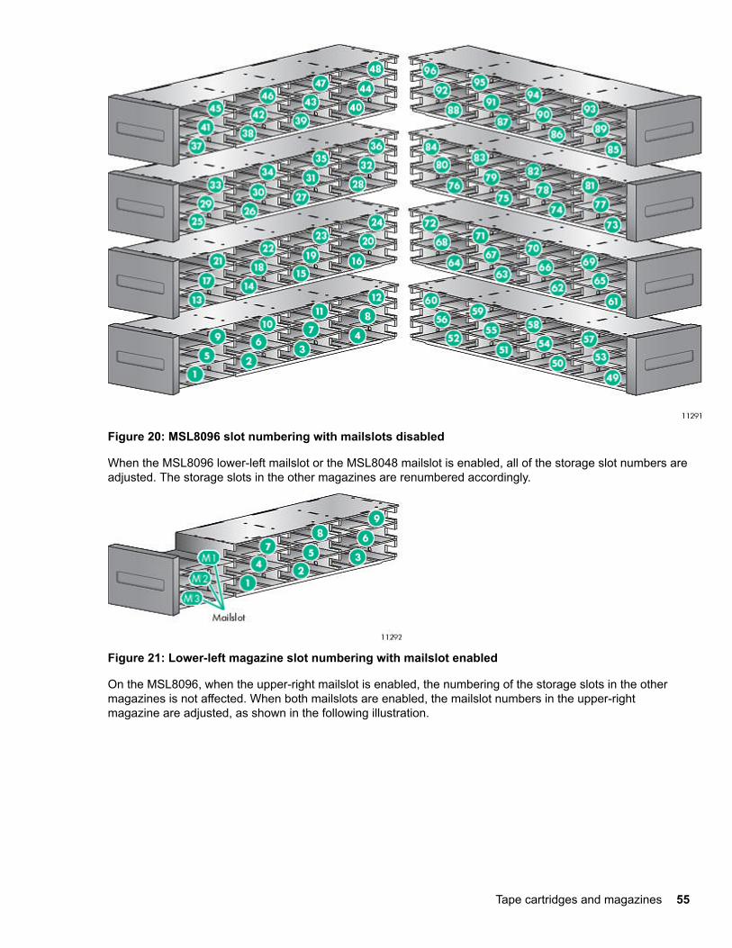
Figure 20: MSL8096 slot numbering with mailslots disabled
When the MSL8096 lower-left mailslot or the MSL8048 mailslot is enabled, all of the storage slot numbers areadjusted. The storage slots in the other magazines are renumbered accordingly.
Figure 21: Lower-left magazine slot numbering with mailslot enabled
On the MSL8096, when the upper-right mailslot is enabled, the numbering of the storage slots in the othermagazines is not affected. When both mailslots are enabled, the mailslot numbers in the upper-rightmagazine are adjusted, as shown in the following illustration.
Tape cartridges and magazines 55
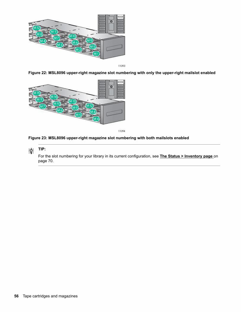
Figure 22: MSL8096 upper-right magazine slot numbering with only the upper-right mailslot enabled
Figure 23: MSL8096 upper-right magazine slot numbering with both mailslots enabled
TIP:
For the slot numbering for your library in its current configuration, see The Status > Inventory page onpage 70.
56 Tape cartridges and magazines
Operating the libraryThe library supports the following operation methods:
• Remote management interface (RMI)— this interface lets you monitor and control the library from a webpage. You can access most library functions from the RMI.
• Operator control panel (OCP) — this interface lets you operate the device from the front panel.
• Host backup software— You can perform any functions provided by the backup software.
NOTE:
Before using the RMI, the library network settings must be configured and the administrator password set.
The remote management interface (RMI)
Overview of the RMIThe RMI lets you monitor and control your device through the World Wide Web (WWW). The RMI hosts adedicated, protected internet site that displays a graphical representation of your device.
Before using the RMI, you must configure the device network settings and set the administratorpassword with the OCP. (See Configuring IPv4 network settings (Configuration > Configure NetworkSettings) on page 110 and Changing the administrator password (Configuration > Change AdminPassword) on page 104.)
To start the RMI, open any HTML browser and enter the IP address of the device in the browser address bar.
TIP:
Check the Help screens in the RMI for additional information. The help pages are updated with mostfirmware updates and often contain technical details that are not contained in this document. To accessRMI help, click Help on the right side of the web page banner, as shown in The Help link on page 61.
The following functions are available through the RMI:
• Identity on page 61
◦ The Identity > Library page on page 61
◦ The Identity > Drive page on page 63
◦ The Identity > Network page on page 65
• Status on page 66
◦ The Status > Library page on page 66
◦ The Status > Drive page on page 68
◦ The Status > Inventory page on page 70
◦ The Status > Security page on page 72
• Configuration on page 73
Operating the library 57
◦ The Configuration > System page on page 73
◦ The Configuration > Security page on page 79
◦ The Configuration > Drive page on page 79
◦ The Configuration > License Key page on page 81
◦ The Configuration > Network page on page 81
◦ The Configuration > Network Management page on page 83
◦ The Configuration > Password page on page 85
◦ The Configuration > Date/Time page on page 86
◦ The Configuration > Log page on page 87
◦ The Configuration > Alerts page on page 87
◦ The Configuration > Save/Restore page on page 88
• Operations on page 88
◦ The Operations > Move Media page on page 89
◦ The Operations > Inventory page on page 89
◦ The Operations > Magazines page on page 89
• Support on page 90
◦ The Support > General Diagnostic page on page 90
◦ The Support > Service page— Service restricted on page 90
◦ The Support > Firmware page on page 90
◦ The Support > Reboot page on page 91
◦ The Support > Library Logs page on page 91
◦ The Support > Drive page on page 92
◦ The Support > Support Ticket page on page 92
Logging in to the library
Prerequisites
• The network settings have been configured from the OCP.
• The administrator password is set.
Procedure
1. Navigate to the library web interface.
58 Logging in to the library
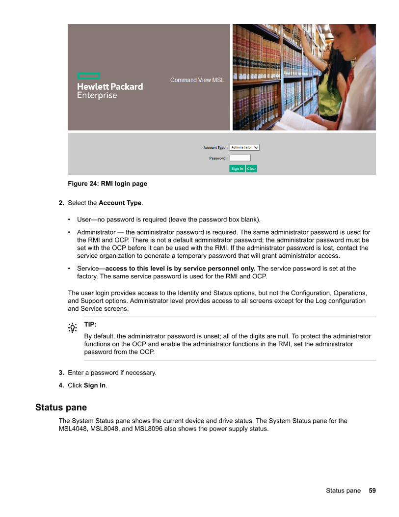
Figure 24: RMI login page
2. Select the Account Type.
• User—no password is required (leave the password box blank).
• Administrator — the administrator password is required. The same administrator password is used forthe RMI and OCP. There is not a default administrator password; the administrator password must beset with the OCP before it can be used with the RMI. If the administrator password is lost, contact theservice organization to generate a temporary password that will grant administrator access.
• Service—access to this level is by service personnel only. The service password is set at thefactory. The same service password is used for the RMI and OCP.
The user login provides access to the Identity and Status options, but not the Configuration, Operations,and Support options. Administrator level provides access to all screens except for the Log configurationand Service screens.
TIP:
By default, the administrator password is unset; all of the digits are null. To protect the administratorfunctions on the OCP and enable the administrator functions in the RMI, set the administratorpassword from the OCP.
3. Enter a password if necessary.
4. Click Sign In.
Status paneThe System Status pane shows the current device and drive status. The System Status pane for theMSL4048, MSL8048, and MSL8096 also shows the power supply status.
Status pane 59
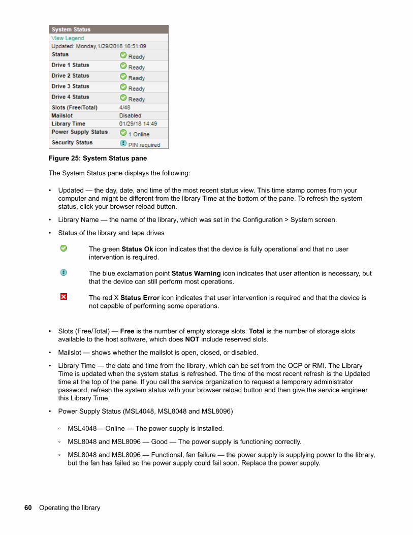
Figure 25: System Status pane
The System Status pane displays the following:
• Updated — the day, date, and time of the most recent status view. This time stamp comes from yourcomputer and might be different from the library Time at the bottom of the pane. To refresh the systemstatus, click your browser reload button.
• Library Name — the name of the library, which was set in the Configuration > System screen.
• Status of the library and tape drives
The green Status Ok icon indicates that the device is fully operational and that no userintervention is required.
The blue exclamation point Status Warning icon indicates that user attention is necessary, butthat the device can still perform most operations.
The red X Status Error icon indicates that user intervention is required and that the device isnot capable of performing some operations.
• Slots (Free/Total) — Free is the number of empty storage slots. Total is the number of storage slotsavailable to the host software, which does NOT include reserved slots.
• Mailslot — shows whether the mailslot is open, closed, or disabled.
• Library Time — the date and time from the library, which can be set from the OCP or RMI. The LibraryTime is updated when the system status is refreshed. The time of the most recent refresh is the Updatedtime at the top of the pane. If you call the service organization to request a temporary administratorpassword, refresh the system status with your browser reload button and then give the service engineerthis Library Time.
• Power Supply Status (MSL4048, MSL8048 and MSL8096)
◦ MSL4048— Online — The power supply is installed.
◦ MSL8048 and MSL8096 — Good — The power supply is functioning correctly.
◦ MSL8048 and MSL8096 — Functional, fan failure — the power supply is supplying power to the library,but the fan has failed so the power supply could fail soon. Replace the power supply.
60 Operating the library
◦ Installed, failed — The power supply installed in the unit is not working and the library no longer hasredundant power. Replace the power supply.
NOTE:
If the MSL4048 has two power supplies and one fails, after a power cycle the library will not recognizethe failed power supply as installed in the library.
The number of power supplies installed in the library is displayed next to the icon.
◦ MSL8048 and MSL8096 — Removed — a power supply was installed in this location before but hasbeen removed. Power Supply 1 will always show Removed when it is missing. Power Supply 2 willshow Removed until the library is rebooted.
• Security Status — indicates the security status when encryption is enabled.
The green Status Ok icon indicates that encryption is enabled, the encryption token is inserted,and no operator attention is required.
The blue exclamation point Status Warning icon indicates that user attention is necessary. Forexample, the token is not inserted or the token PIN has not been entered. For additionalinformation, see the event log.
The red X Status Error icon indicates that user intervention is required and that the device isnot capable of encrypting data.
The Help linkFor additional information about fields on the RMI screens, click the Help link in the upper right corner. Thehelp pages are updated with most firmware updates and often contain technical details that are not containedin this document.
Figure 26: Help link
Identity
The Identity > Library pageThe library provides static information about the device.
The Help link 61
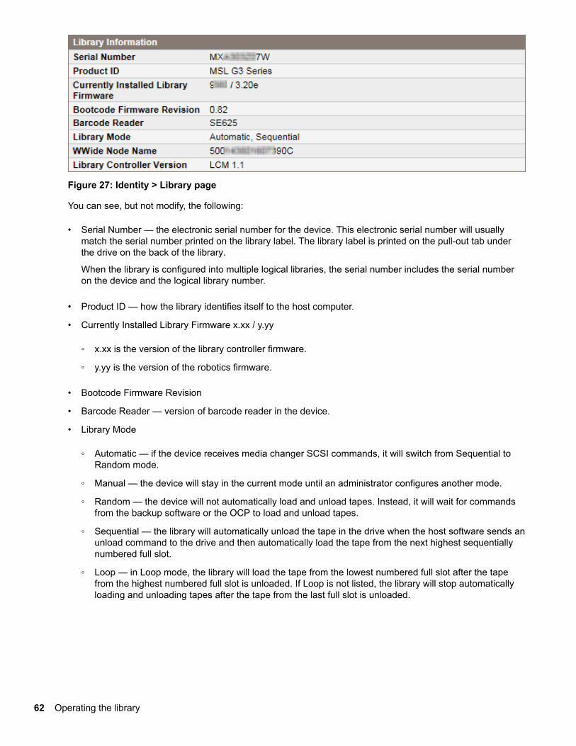
Figure 27: Identity > Library page
You can see, but not modify, the following:
• Serial Number — the electronic serial number for the device. This electronic serial number will usuallymatch the serial number printed on the library label. The library label is printed on the pull-out tab underthe drive on the back of the library.
When the library is configured into multiple logical libraries, the serial number includes the serial numberon the device and the logical library number.
• Product ID — how the library identifies itself to the host computer.
• Currently Installed Library Firmware x.xx / y.yy
◦ x.xx is the version of the library controller firmware.
◦ y.yy is the version of the robotics firmware.
• Bootcode Firmware Revision
• Barcode Reader — version of barcode reader in the device.
• Library Mode
◦ Automatic — if the device receives media changer SCSI commands, it will switch from Sequential toRandom mode.
◦ Manual — the device will stay in the current mode until an administrator configures another mode.
◦ Random — the device will not automatically load and unload tapes. Instead, it will wait for commandsfrom the backup software or the OCP to load and unload tapes.
◦ Sequential — the library will automatically unload the tape in the drive when the host software sends anunload command to the drive and then automatically load the tape from the next highest sequentiallynumbered full slot.
◦ Loop — in Loop mode, the library will load the tape from the lowest numbered full slot after the tapefrom the highest numbered full slot is unloaded. If Loop is not listed, the library will stop automaticallyloading and unloading tapes after the tape from the last full slot is unloaded.
62 Operating the library
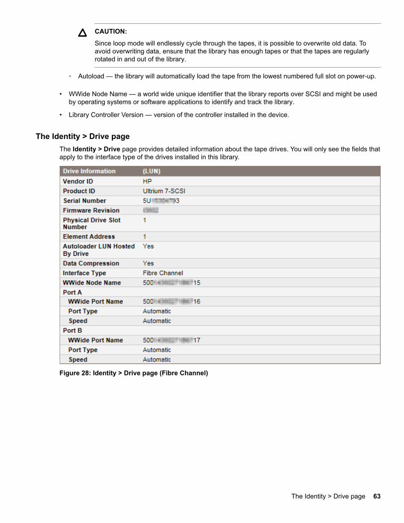
CAUTION:
Since loop mode will endlessly cycle through the tapes, it is possible to overwrite old data. Toavoid overwriting data, ensure that the library has enough tapes or that the tapes are regularlyrotated in and out of the library.
◦ Autoload — the library will automatically load the tape from the lowest numbered full slot on power-up.
• WWide Node Name — a world wide unique identifier that the library reports over SCSI and might be usedby operating systems or software applications to identify and track the library.
• Library Controller Version — version of the controller installed in the device.
The Identity > Drive pageThe Identity > Drive page provides detailed information about the tape drives. You will only see the fields thatapply to the interface type of the drives installed in this library.
Figure 28: Identity > Drive page (Fibre Channel)
The Identity > Drive page 63
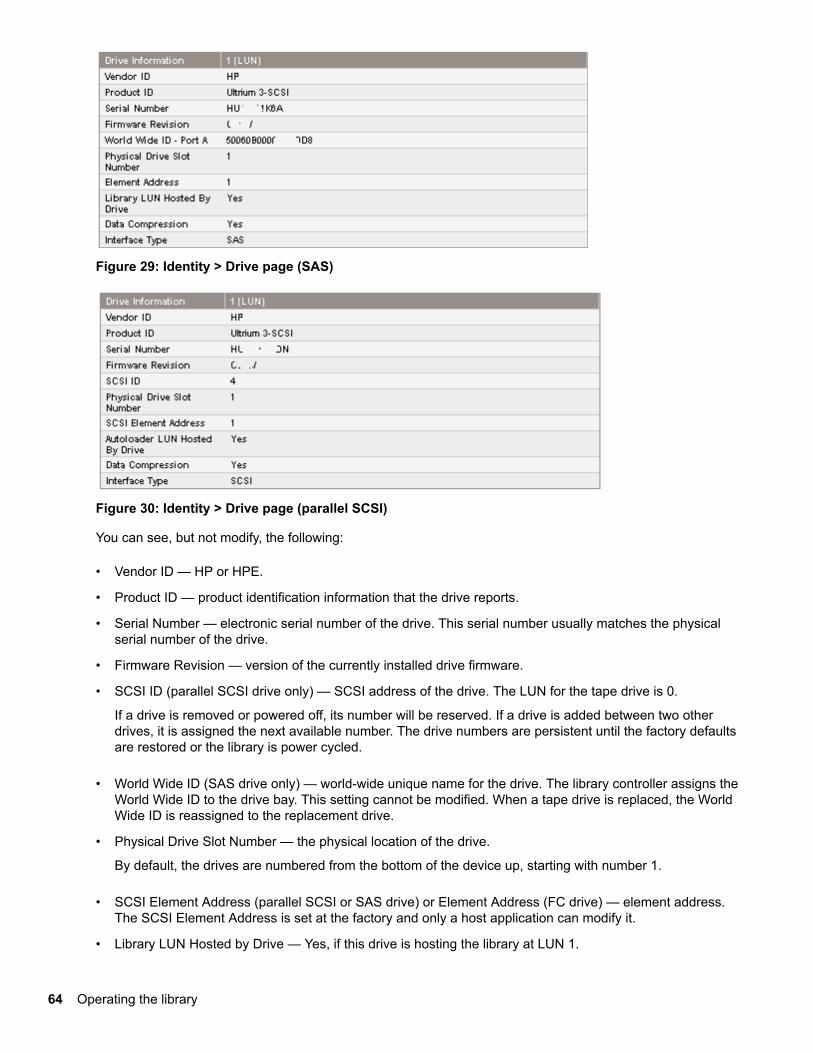
Figure 29: Identity > Drive page (SAS)
Figure 30: Identity > Drive page (parallel SCSI)
You can see, but not modify, the following:
• Vendor ID — HP or HPE.
• Product ID — product identification information that the drive reports.
• Serial Number — electronic serial number of the drive. This serial number usually matches the physicalserial number of the drive.
• Firmware Revision — version of the currently installed drive firmware.
• SCSI ID (parallel SCSI drive only) — SCSI address of the drive. The LUN for the tape drive is 0.
If a drive is removed or powered off, its number will be reserved. If a drive is added between two otherdrives, it is assigned the next available number. The drive numbers are persistent until the factory defaultsare restored or the library is power cycled.
• World Wide ID (SAS drive only) — world-wide unique name for the drive. The library controller assigns theWorld Wide ID to the drive bay. This setting cannot be modified. When a tape drive is replaced, the WorldWide ID is reassigned to the replacement drive.
• Physical Drive Slot Number — the physical location of the drive.
By default, the drives are numbered from the bottom of the device up, starting with number 1.
• SCSI Element Address (parallel SCSI or SAS drive) or Element Address (FC drive) — element address.The SCSI Element Address is set at the factory and only a host application can modify it.
• Library LUN Hosted by Drive — Yes, if this drive is hosting the library at LUN 1.
64 Operating the library
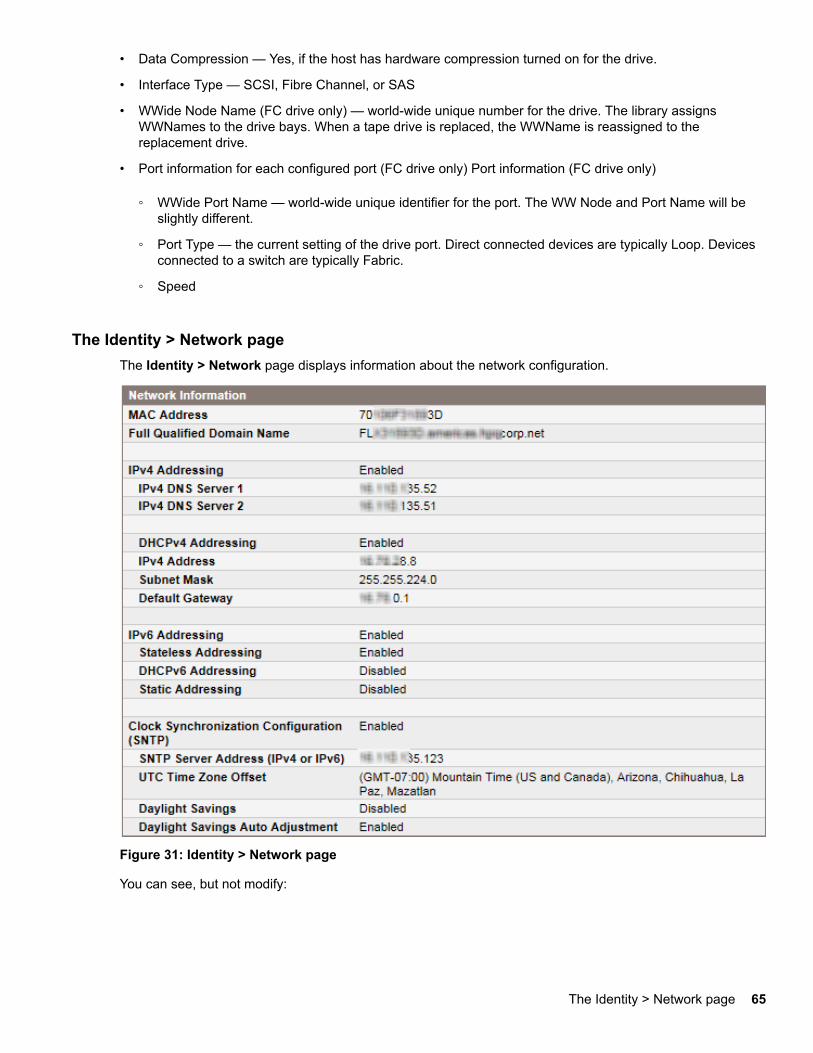
• Data Compression — Yes, if the host has hardware compression turned on for the drive.
• Interface Type — SCSI, Fibre Channel, or SAS
• WWide Node Name (FC drive only) — world-wide unique number for the drive. The library assignsWWNames to the drive bays. When a tape drive is replaced, the WWName is reassigned to thereplacement drive.
• Port information for each configured port (FC drive only) Port information (FC drive only)
◦ WWide Port Name — world-wide unique identifier for the port. The WW Node and Port Name will beslightly different.
◦ Port Type — the current setting of the drive port. Direct connected devices are typically Loop. Devicesconnected to a switch are typically Fabric.
◦ Speed
The Identity > Network pageThe Identity > Network page displays information about the network configuration.
Figure 31: Identity > Network page
You can see, but not modify:
The Identity > Network page 65
• MAC Address — a unique identifier for the library controller network interface
• Full Qualified Domain Name — the fully qualified domain name for the library
• Clock Synchronization Configuration (SNTP) — When Enabled, the library displays the current time anddate from the configured SNTP server.
When IPv4 Addressing is Enabled, you can see, but not modify:
• IPv4 DNS Server 1 and IPv4 DNS Server 2 — addresses of the configured DNS servers used whenDHCP Addressing is not Enabled.
• DHCPv4 Addressing — When Enabled, the library will request an IP address from a DHCP server eachtime the device is booted.
• IPv4 Address — the library network address
• Subnet Mask — The network mask of the library controller used when DHCP Addressing is not Enabled.
• Default Gateway — the gateway used when DHCP Addressing is not Enabled.
When IPv6 Addressing is Enabled, you can see, but not modify:
• Stateless Addressing — when Enabled, the device will generate an address for itself based on the routinginformation obtained from a router advertisement and the MAC address. The device can manage up to fiveglobal addresses at the same time, which can be assigned from different routers.
• DHCPv6 Addressing — when Enabled, the library will request an IP address from a DHCP server eachtime the device is booted.
• Static Addressing — when Enabled, the device will use a statically configured address.
• Static Assigned Address — the IPv6 address when Static Addressing Enabled is On.
Status
The Status > Library pageThe Status > Library page displays dynamic information about the device. When you click Refresh, thestatus is updated immediately.
66 Status
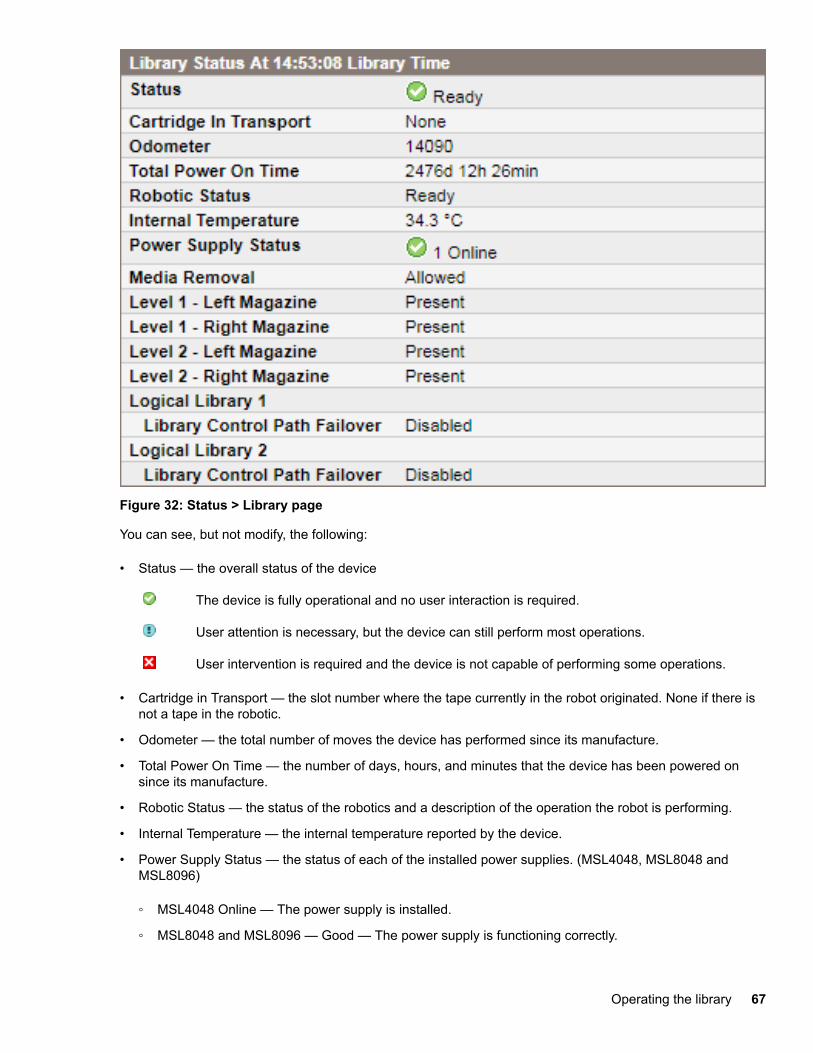
Figure 32: Status > Library page
You can see, but not modify, the following:
• Status — the overall status of the device
The device is fully operational and no user interaction is required.
User attention is necessary, but the device can still perform most operations.
User intervention is required and the device is not capable of performing some operations.
• Cartridge in Transport — the slot number where the tape currently in the robot originated. None if there isnot a tape in the robotic.
• Odometer — the total number of moves the device has performed since its manufacture.
• Total Power On Time — the number of days, hours, and minutes that the device has been powered onsince its manufacture.
• Robotic Status — the status of the robotics and a description of the operation the robot is performing.
• Internal Temperature — the internal temperature reported by the device.
• Power Supply Status — the status of each of the installed power supplies. (MSL4048, MSL8048 andMSL8096)
◦ MSL4048 Online — The power supply is installed.
◦ MSL8048 and MSL8096 — Good — The power supply is functioning correctly.
Operating the library 67
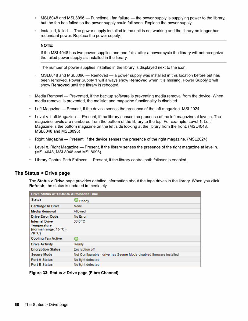
◦ MSL8048 and MSL8096 — Functional, fan failure — the power supply is supplying power to the library,but the fan has failed so the power supply could fail soon. Replace the power supply.
◦ Installed, failed — The power supply installed in the unit is not working and the library no longer hasredundant power. Replace the power supply.
NOTE:
If the MSL4048 has two power supplies and one fails, after a power cycle the library will not recognizethe failed power supply as installed in the library.
The number of power supplies installed in the library is displayed next to the icon.
◦ MSL8048 and MSL8096 — Removed — a power supply was installed in this location before but hasbeen removed. Power Supply 1 will always show Removed when it is missing. Power Supply 2 willshow Removed until the library is rebooted.
• Media Removal — Prevented, if the backup software is preventing media removal from the device. Whenmedia removal is prevented, the mailslot and magazine functionality is disabled.
• Left Magazine — Present, if the device senses the presence of the left magazine. MSL2024
• Level n. Left Magazine — Present, if the library senses the presence of the left magazine at level n. Themagazine levels are numbered from the bottom of the library to the top. For example, Level 1. LeftMagazine is the bottom magazine on the left side looking at the library from the front. (MSL4048,MSL8048 and MSL8096)
• Right Magazine — Present, if the device senses the presence of the right magazine. (MSL2024)
• Level n. Right Magazine — Present, if the library senses the presence of the right magazine at level n.(MSL4048, MSL8048 and MSL8096)
• Library Control Path Failover — Present, if the library control path failover is enabled.
The Status > Drive pageThe Status > Drive page provides detailed information about the tape drives in the library. When you clickRefresh, the status is updated immediately.
Figure 33: Status > Drive page (Fibre Channel)
68 The Status > Drive page
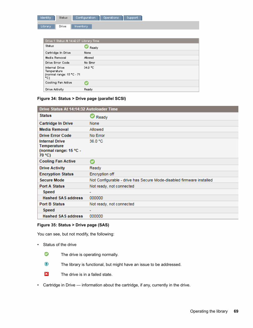
Figure 34: Status > Drive page (parallel SCSI)
Figure 35: Status > Drive page (SAS)
You can see, but not modify, the following:
• Status of the drive
The drive is operating normally.
The library is functional, but might have an issue to be addressed.
The drive is in a failed state.
• Cartridge in Drive — information about the cartridge, if any, currently in the drive.
Operating the library 69
• Media Removal — Prevented if the backup software is preventing media removal from the library. Whenmedia removal is prevented, the library will not open the mailslot or magazines.
• Drive Error Code — the current drive error code if the drive is in a failed state. See Drive error codes onpage 198 for a list of drive error codes.
• Internal Drive Temperature — internal temperature reported by the drive. The normal temperature range isprovided for reference and varies depending on the type of tape drive. If there is any possibility of errordue to temperature, the tape drive will send out error events.
NOTE:
The Internal Drive Temperature is not the temperature of the tape path in the drive nor is this temperaturethe operating environment temperature.
• Cooling Fan Active — On when the cooling fan is on
• Drive Activity — the current drive activity
• Encryption status — The status of encryption on the drive.
• Secure Mode (LTO-7 and later drives)
◦ Enabled — the drive has Secure Mode-enabled firmware installed and is in a FIPS Support Modeenabled partition
◦ Disabled — the drive has Secure Mode-enabled firmware installed and is in a FIPS Support Modedisabled partition
◦ Not Configurable — The drive has Secure Mode-disabled firmware installed. The drive is running thenormal firmware image, which is FIPS Secure Mode-disabled.
• Port A Status and Port B Status — status of the ports
• Speed (Fibre Channel and SAS drives) — the current speed setting of the drive port
• Port Type (Fibre Channel drives only) — the current setting of the drive port. Direct connected devices aretypically Loop. Devices connected to a switch are typically Fabric.
• N-Port ID (Fibre Channel drives only) — Fabric address. Only relevant when in Fabric mode.
• ALPA (Fibre Channel drives only) — Loop address. Only relevant when in Loop mode.
• Hashed SAS address — A short version of the SAS World Wide Identifier (WWI) that is generated using awell-defined hash algorithm and is suitable for device identification in most systems. Some managementsoftware might report this value.
The Status > Inventory pageThe Status > Inventory page provides detailed information about the tape cartridges in the tape drives, witha summary of tapes in magazine slots.
70 The Status > Inventory page
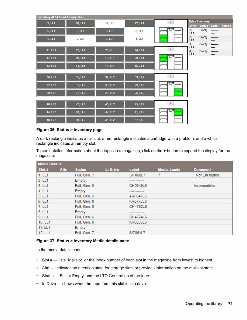
Figure 36: Status > Inventory page
A dark rectangle indicates a full slot, a red rectangle indicates a cartridge with a problem, and a whiterectangle indicates an empty slot.
To see detailed information about the tapes in a magazine, click on the + button to expand the display for themagazine.
Figure 37: Status > Inventory Media details pane
In the media details pane:
• Slot # — lists “Mailslot” or the index number of each slot in the magazine from lowest to highest.
• Attn — indicates an attention state for storage slots or provides information on the mailslot state.
• Status — Full or Empty, and the LTO Generation of the tape.
• In Drive — shows when the tape from this slot is in a drive.
Operating the library 71
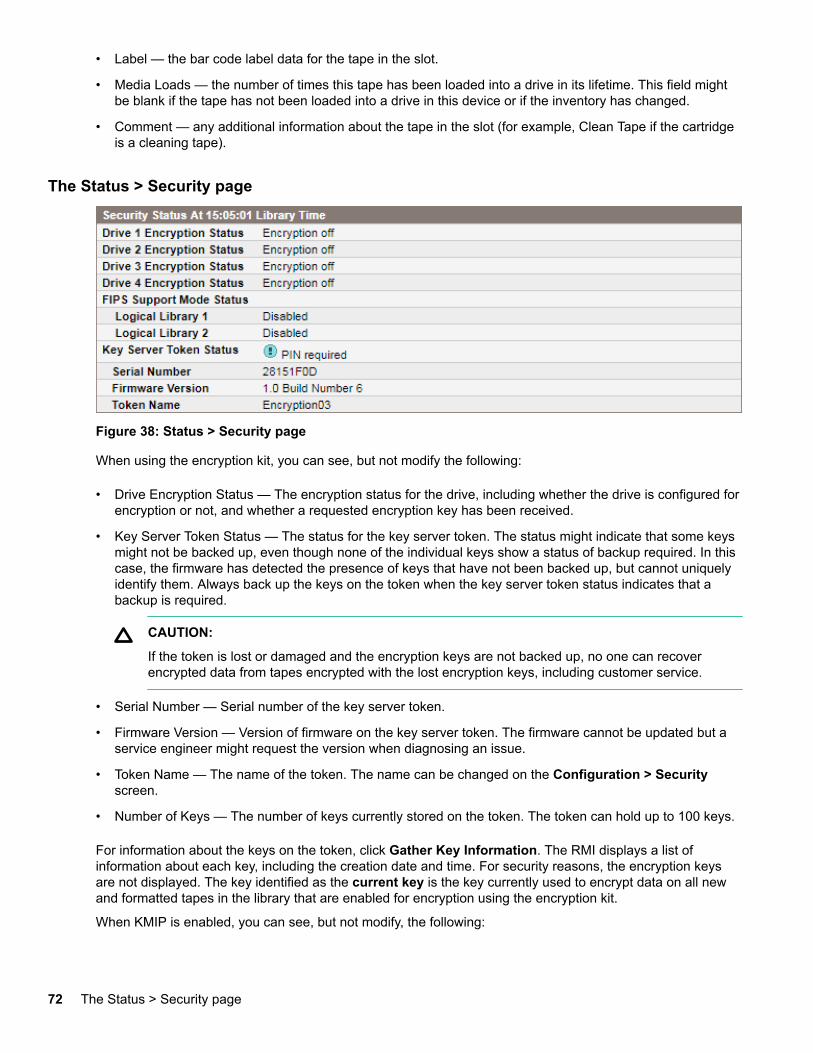
• Label — the bar code label data for the tape in the slot.
• Media Loads — the number of times this tape has been loaded into a drive in its lifetime. This field mightbe blank if the tape has not been loaded into a drive in this device or if the inventory has changed.
• Comment — any additional information about the tape in the slot (for example, Clean Tape if the cartridgeis a cleaning tape).
The Status > Security page
Figure 38: Status > Security page
When using the encryption kit, you can see, but not modify the following:
• Drive Encryption Status — The encryption status for the drive, including whether the drive is configured forencryption or not, and whether a requested encryption key has been received.
• Key Server Token Status — The status for the key server token. The status might indicate that some keysmight not be backed up, even though none of the individual keys show a status of backup required. In thiscase, the firmware has detected the presence of keys that have not been backed up, but cannot uniquelyidentify them. Always back up the keys on the token when the key server token status indicates that abackup is required.
CAUTION:
If the token is lost or damaged and the encryption keys are not backed up, no one can recoverencrypted data from tapes encrypted with the lost encryption keys, including customer service.
• Serial Number — Serial number of the key server token.
• Firmware Version — Version of firmware on the key server token. The firmware cannot be updated but aservice engineer might request the version when diagnosing an issue.
• Token Name — The name of the token. The name can be changed on the Configuration > Securityscreen.
• Number of Keys — The number of keys currently stored on the token. The token can hold up to 100 keys.
For information about the keys on the token, click Gather Key Information. The RMI displays a list ofinformation about each key, including the creation date and time. For security reasons, the encryption keysare not displayed. The key identified as the current key is the key currently used to encrypt data on all newand formatted tapes in the library that are enabled for encryption using the encryption kit.
When KMIP is enabled, you can see, but not modify, the following:
72 The Status > Security page
• Drive Encryption Status — The encryption status for the drive, including whether the drive is configured forencryption or not, and whether a requested encryption key has been received. To update the status, clickRefresh.
• Security Status — Shows whether KMIP key management is configured or not. Configure KMIP in theConfiguration > Security screen.
• Signed Certificate — Displays information about the library SSL client certificate.
◦ Serial Number — The serial number provided by the certificate authority that signed the certificate.
◦ Status — Indicates whether the library deems the certificate to be valid or not.
◦ Valid Between Dates — Displays the time frame when the certificate is valid. The certificate authority,which is typically on the KMIP server, assigns these dates.
◦ Common Name — A name that the library assigns automatically. Some KMIP servers require thisname to match the library KMIP client user name.
Configuration
The Configuration > System pageUse the Configuration > System page to modify the system configuration.
System configuration changes are only applied after Apply or Submit is selected. After making the selection,a warning page informs you of the impact of the proposed change. In some cases, a pop-up screen asks youto confirm the change. Many changes also require the device to reboot. You might need to click Refresh tosee the changes.
Configuration 73
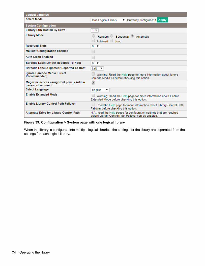
Figure 39: Configuration > System page with one logical library
When the library is configured into multiple logical libraries, the settings for the library are separated from thesettings for each logical library.
74 Operating the library
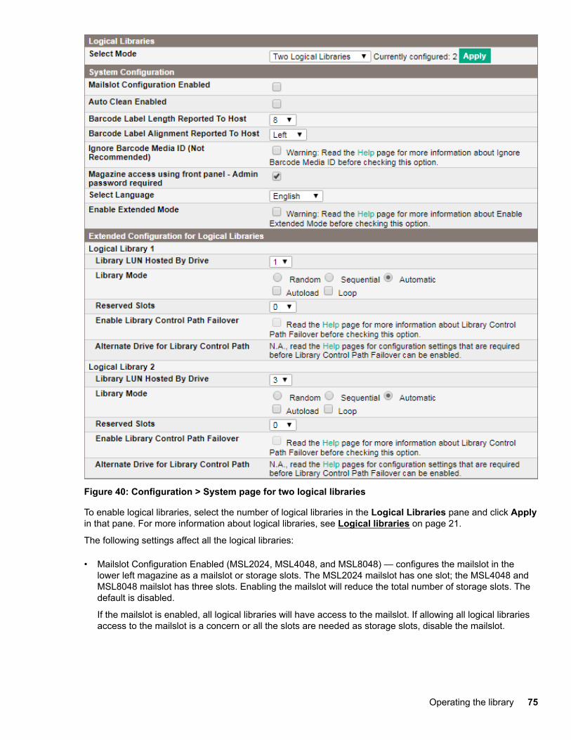
Figure 40: Configuration > System page for two logical libraries
To enable logical libraries, select the number of logical libraries in the Logical Libraries pane and click Applyin that pane. For more information about logical libraries, see Logical libraries on page 21.
The following settings affect all the logical libraries:
• Mailslot Configuration Enabled (MSL2024, MSL4048, and MSL8048) — configures the mailslot in thelower left magazine as a mailslot or storage slots. The MSL2024 mailslot has one slot; the MSL4048 andMSL8048 mailslot has three slots. Enabling the mailslot will reduce the total number of storage slots. Thedefault is disabled.
If the mailslot is enabled, all logical libraries will have access to the mailslot. If allowing all logical librariesaccess to the mailslot is a concern or all the slots are needed as storage slots, disable the mailslot.
Operating the library 75
CAUTION:
The mailslot is located where the lowest numbered storage slot would be. Enabling and disabling themailslot renumbers all the other storage slots. After enabling or disabling the mailslot, update thebackup software inventory. You might also need to reconfigure the backup software to adjust thenumber of storage slots and presence of the mailslot.
• Mailslot Configuration (MSL8096) — configures the mailslot in the lower-left magazine and upper-rightmagazine as mailslots or storage slots. Enabling a mailslot will reduce the number of storage slots. Thedefault is no mailslots enabled.
If the mailslot is enabled, all logical libraries will have access to the mailslot. If allowing all logical librariesaccess to the mailslot is a concern or all the slots are needed as storage slots, disable the mailslot.
Enable mailslots by selecting the mailslot slots in the Mailslot Configuration drop-down list.
◦ 0 disables both mailslots.
◦ 3 enables the lower-left mailslot only.
◦ 12 enables the upper-right mailslot only.
◦ 15 enables both mailslots.
CAUTION:
The lower-left mailslot is located where the lowest numbered storage slots would be. Enabling anddisabling it will renumber all the storage slots. On the MSL8096, enabling or disabling the lower-leftmagazine also affects the numbering of the slots in the upper-right mailslot. After enabling ordisabling the lower left mailslot, update the backup software inventory. You might also need toreconfigure the backup software to adjust the number of storage slots and presence of the mailslot.
• Auto Clean Enabled — When auto clean is enabled, the device automatically loads a cleaning cartridgewhen a tape drive is ready for cleaning. The device identifies a cleaning cartridge if it has a bar code labelthat starts with CLN. It can only identify an unlabeled cleaning tape after it has been loaded into the tapedrive.
The device can use a cleaning cartridge from any slot, even if the slot is not active. The device tracks theusage count for each of the cleaning cartridges. When multiple cleaning cartridges are available, thedevice will first choose an unknown cleaning cartridge so the device can start tracking the cartridge usagecount. If the device knows the usage count for all the cleaning cartridges, the device will choose the onewith the highest usage count.
Auto cleaning is disabled by default. You can enable automatic cleaning even if there are no cleaningcartridges in the device. In this case, the device will display a warning message.
The tape library can load a cleaning cartridge from any logical library to any tape drive.
CAUTION:
Only enable automatic cleaning in either the backup application or the device, not both.
• Barcode Label Length Reported to Host — the number of bar code characters reported to the hostapplication. This option provides interchange compatibility with libraries with more limited bar code readingcapabilities. The maximum length is 15 and the default is 8.
76 Operating the library
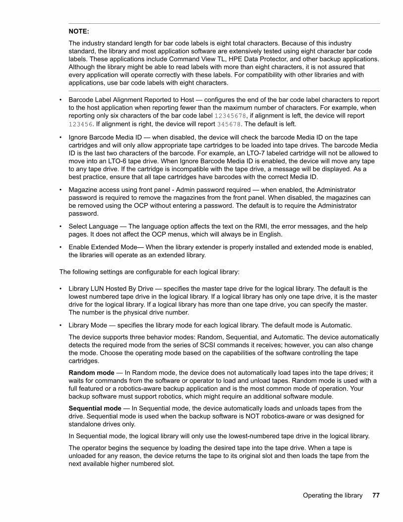
NOTE:
The industry standard length for bar code labels is eight total characters. Because of this industrystandard, the library and most application software are extensively tested using eight character bar codelabels. These applications include Command View TL, HPE Data Protector, and other backup applications.Although the library might be able to read labels with more than eight characters, it is not assured thatevery application will operate correctly with these labels. For compatibility with other libraries and withapplications, use bar code labels with eight characters.
• Barcode Label Alignment Reported to Host — configures the end of the bar code label characters to reportto the host application when reporting fewer than the maximum number of characters. For example, whenreporting only six characters of the bar code label 12345678, if alignment is left, the device will report123456. If alignment is right, the device will report 345678. The default is left.
• Ignore Barcode Media ID — when disabled, the device will check the barcode Media ID on the tapecartridges and will only allow appropriate tape cartridges to be loaded into tape drives. The barcode MediaID is the last two characters of the barcode. For example, an LTO-7 labeled cartridge will not be allowed tomove into an LTO-6 tape drive. When Ignore Barcode Media ID is enabled, the device will move any tapeto any tape drive. If the cartridge is incompatible with the tape drive, a message will be displayed. As abest practice, ensure that all tape cartridges have barcodes with the correct Media ID.
• Magazine access using front panel - Admin password required — when enabled, the Administratorpassword is required to remove the magazines from the front panel. When disabled, the magazines canbe removed using the OCP without entering a password. The default is to require the Administratorpassword.
• Select Language — The language option affects the text on the RMI, the error messages, and the helppages. It does not affect the OCP menus, which will always be in English.
• Enable Extended Mode— When the library extender is properly installed and extended mode is enabled,the libraries will operate as an extended library.
The following settings are configurable for each logical library:
• Library LUN Hosted By Drive — specifies the master tape drive for the logical library. The default is thelowest numbered tape drive in the logical library. If a logical library has only one tape drive, it is the masterdrive for the logical library. If a logical library has more than one tape drive, you can specify the master.The number is the physical drive number.
• Library Mode — specifies the library mode for each logical library. The default mode is Automatic.
The device supports three behavior modes: Random, Sequential, and Automatic. The device automaticallydetects the required mode from the series of SCSI commands it receives; however, you can also changethe mode. Choose the operating mode based on the capabilities of the software controlling the tapecartridges.
Random mode — In Random mode, the device does not automatically load tapes into the tape drives; itwaits for commands from the software or operator to load and unload tapes. Random mode is used with afull featured or a robotics-aware backup application and is the most common mode of operation. Yourbackup software must support robotics, which might require an additional software module.
Sequential mode — In Sequential mode, the device automatically loads and unloads tapes from thedrive. Sequential mode is used when the backup software is NOT robotics-aware or was designed forstandalone drives only.
In Sequential mode, the logical library will only use the lowest-numbered tape drive in the logical library.
The operator begins the sequence by loading the desired tape into the tape drive. When a tape isunloaded for any reason, the device returns the tape to its original slot and then loads the tape from thenext available higher numbered slot.
Operating the library 77
To determine more specifically how you want tapes loaded into the tape drive while in Sequential mode,set the Loop and Autoload options.
◦ When Autoload mode is set, the device automatically loads the cartridge from the lowest-numberedfull slot into the tape drive. It then follows standard sequential operation. After configuring Autoloadmode, you must do one of the following for Autoload mode to take effect:
– Power cycle the device from the front panel.
– Reboot the device from the RMI Support > Reboot screen.
– Move the lowest-numbered cartridge to the drive before starting the backup application. If themailslot is enabled, the lowest cartridge location will be in the mailslot.
◦ When Loop mode is on, the original first cartridge in the sequence is reloaded after the device hascycled through all available cartridges. If Loop mode is off and the last cartridge has been unloaded,the device stops loading cartridges. The device waits until an operator loads another tape.
CAUTION:
Use caution when choosing Loop mode because it makes it possible to overwrite data onpreviously written cartridges.
When the device is partitioned into logical libraries, each logical library operates as an independent library.The device only loads tapes from the slots associated with one logical library into the tape drive associatedwith that logical library. The library will not load tapes from slots associated with another logical library.Only the lowest-numbered tape drive in a multidrive logical library will be used.
Automatic mode: In Automatic mode, the device switches from Sequential mode into Random modewhen it receives certain SCSI commands. Automatic mode is the default setting.
• Reserved Slots — The number of slots in the logical library that are not available to the backup software.You can store cleaning tapes in reserved slots, or leave reserved slots empty. The slots are reserved fromthe highest slot number down. The default is to make the maximum number of slots active. Each logicallibrary must have at least two active slots.
• Enable Library Control Path Failover — This option provides a mechanism where a library control pathhosted by a Fibre Channel drive can be reassigned to an alternative drive retaining all worldwide names,configuration settings, and with minimal interruption to current operation. The reassignment takes placedwhen the primary master drive is powered off for service. Reassignment can allow a backup to completewhen the master drive suffers a problem and must be removed for service.
The Alternate Drive for Library Control Path will be displayed as N.A until these requirements are met:
◦ The library must have two or more LTO-5 or LTO-6 Fibre Channel drives of the same type (for example,LTO-generation and form factor).
◦ If the library is partitioned into multiple logical libraries, each logical library must contain at least twoLTO-5 or LTO-6 Fibre Channel drives.
◦ A host connection through a SAN switch with NPIV is enabled for associated ports.
◦ All drive ports are configured as Fabric.
78 Operating the library
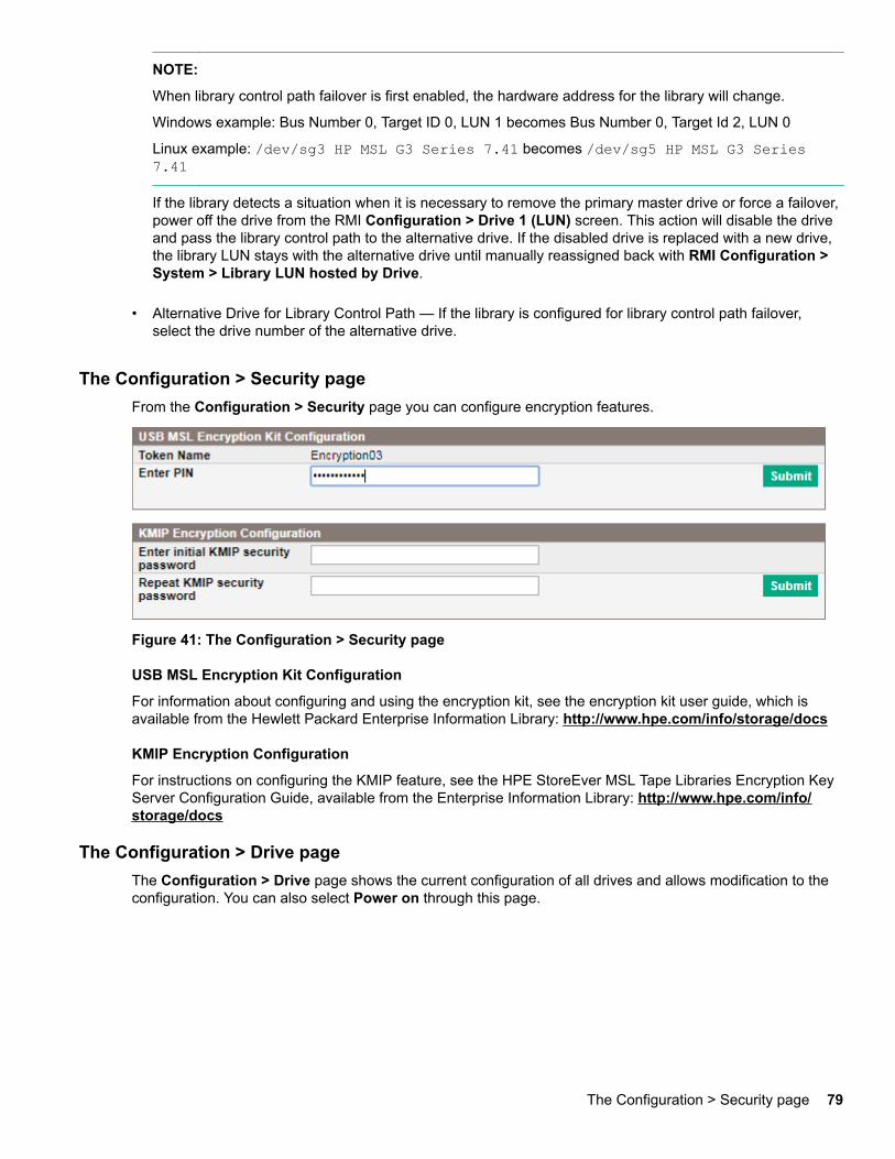
NOTE:
When library control path failover is first enabled, the hardware address for the library will change.
Windows example: Bus Number 0, Target ID 0, LUN 1 becomes Bus Number 0, Target Id 2, LUN 0
Linux example: /dev/sg3 HP MSL G3 Series 7.41 becomes /dev/sg5 HP MSL G3 Series7.41
If the library detects a situation when it is necessary to remove the primary master drive or force a failover,power off the drive from the RMI Configuration > Drive 1 (LUN) screen. This action will disable the driveand pass the library control path to the alternative drive. If the disabled drive is replaced with a new drive,the library LUN stays with the alternative drive until manually reassigned back with RMI Configuration >System > Library LUN hosted by Drive.
• Alternative Drive for Library Control Path — If the library is configured for library control path failover,select the drive number of the alternative drive.
The Configuration > Security pageFrom the Configuration > Security page you can configure encryption features.
Figure 41: The Configuration > Security page
USB MSL Encryption Kit Configuration
For information about configuring and using the encryption kit, see the encryption kit user guide, which isavailable from the Hewlett Packard Enterprise Information Library: http://www.hpe.com/info/storage/docs
KMIP Encryption Configuration
For instructions on configuring the KMIP feature, see the HPE StoreEver MSL Tape Libraries Encryption KeyServer Configuration Guide, available from the Enterprise Information Library: http://www.hpe.com/info/storage/docs
The Configuration > Drive pageThe Configuration > Drive page shows the current configuration of all drives and allows modification to theconfiguration. You can also select Power on through this page.
The Configuration > Security page 79
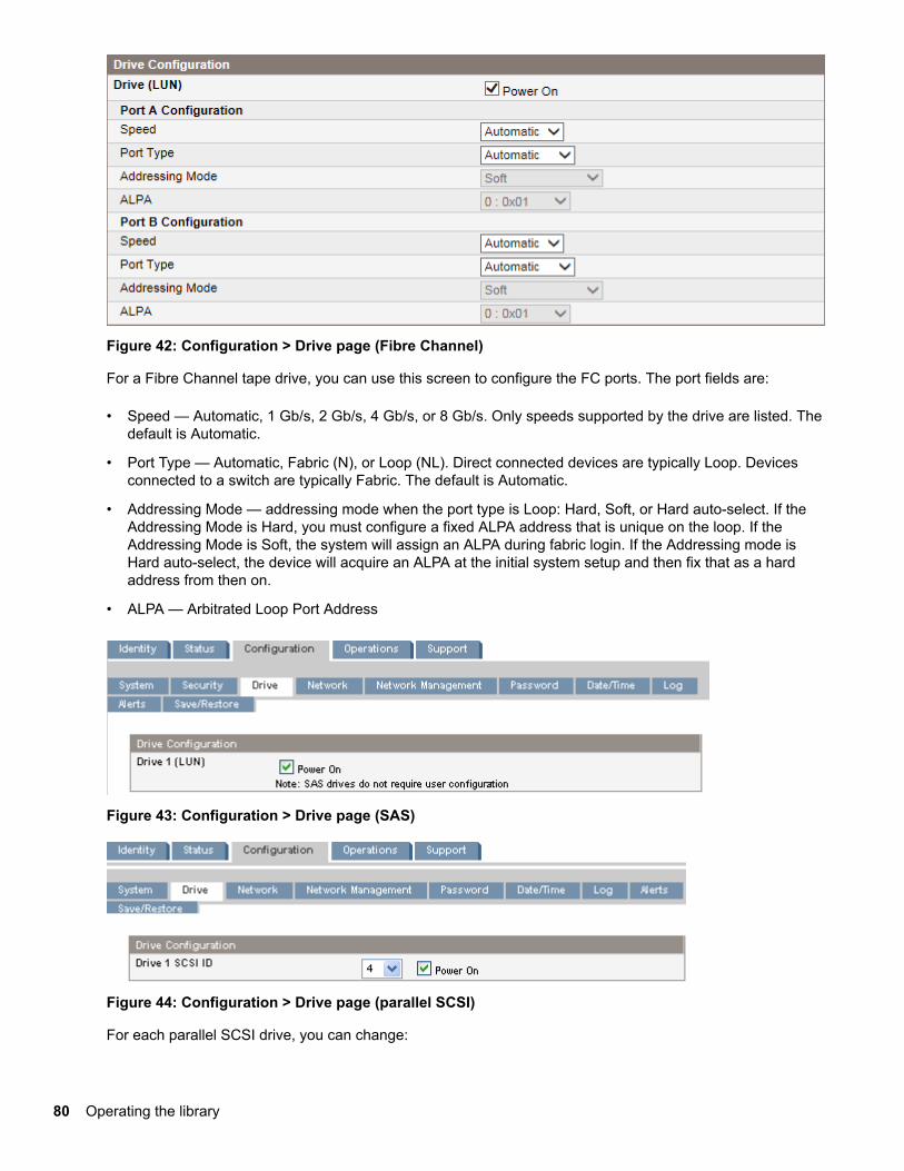
Figure 42: Configuration > Drive page (Fibre Channel)
For a Fibre Channel tape drive, you can use this screen to configure the FC ports. The port fields are:
• Speed — Automatic, 1 Gb/s, 2 Gb/s, 4 Gb/s, or 8 Gb/s. Only speeds supported by the drive are listed. Thedefault is Automatic.
• Port Type — Automatic, Fabric (N), or Loop (NL). Direct connected devices are typically Loop. Devicesconnected to a switch are typically Fabric. The default is Automatic.
• Addressing Mode — addressing mode when the port type is Loop: Hard, Soft, or Hard auto-select. If theAddressing Mode is Hard, you must configure a fixed ALPA address that is unique on the loop. If theAddressing Mode is Soft, the system will assign an ALPA during fabric login. If the Addressing mode isHard auto-select, the device will acquire an ALPA at the initial system setup and then fix that as a hardaddress from then on.
• ALPA — Arbitrated Loop Port Address
Figure 43: Configuration > Drive page (SAS)
Figure 44: Configuration > Drive page (parallel SCSI)
For each parallel SCSI drive, you can change:
80 Operating the library
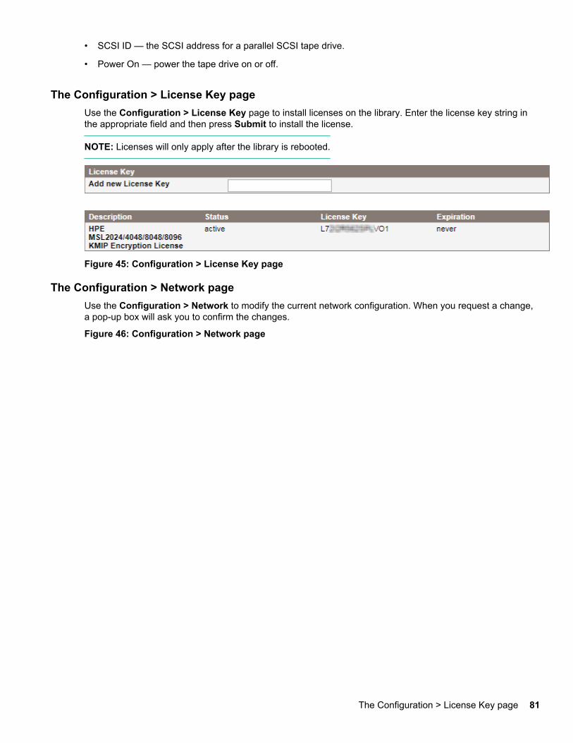
• SCSI ID — the SCSI address for a parallel SCSI tape drive.
• Power On — power the tape drive on or off.
The Configuration > License Key pageUse the Configuration > License Key page to install licenses on the library. Enter the license key string inthe appropriate field and then press Submit to install the license.
NOTE: Licenses will only apply after the library is rebooted.
Figure 45: Configuration > License Key page
The Configuration > Network pageUse the Configuration > Network to modify the current network configuration. When you request a change,a pop-up box will ask you to confirm the changes.
Figure 46: Configuration > Network page
The Configuration > License Key page 81
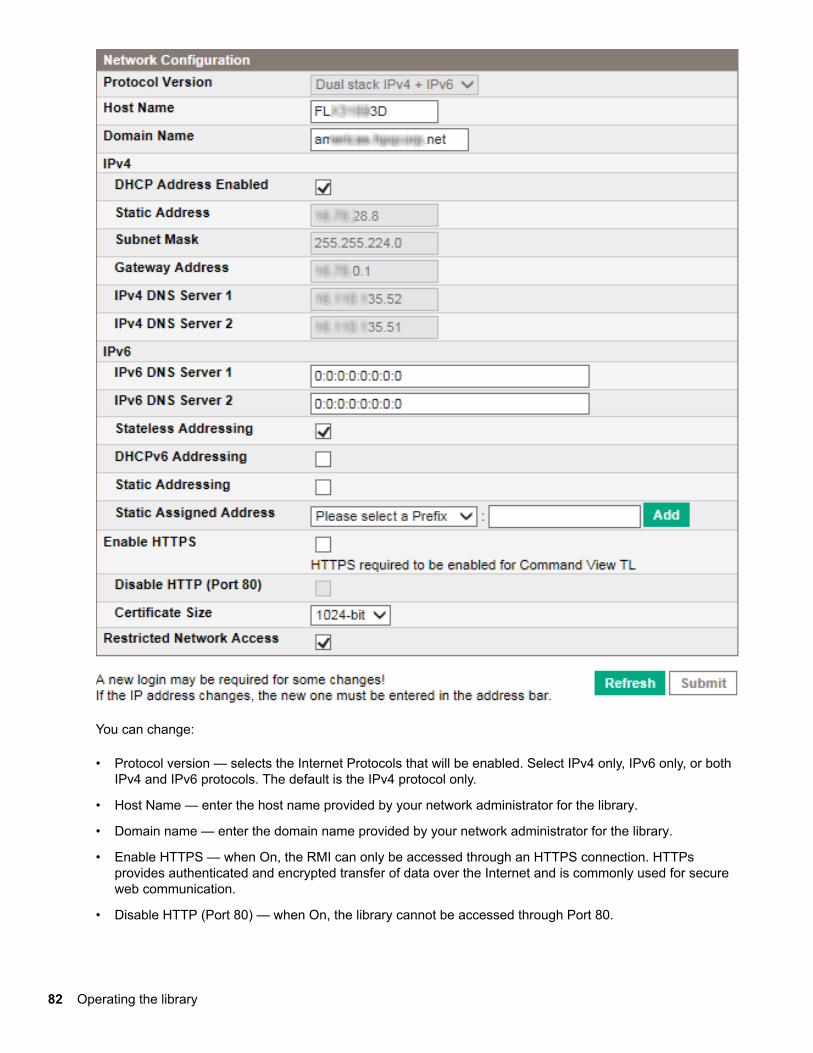
You can change:
• Protocol version — selects the Internet Protocols that will be enabled. Select IPv4 only, IPv6 only, or bothIPv4 and IPv6 protocols. The default is the IPv4 protocol only.
• Host Name — enter the host name provided by your network administrator for the library.
• Domain name — enter the domain name provided by your network administrator for the library.
• Enable HTTPS — when On, the RMI can only be accessed through an HTTPS connection. HTTPsprovides authenticated and encrypted transfer of data over the Internet and is commonly used for secureweb communication.
• Disable HTTP (Port 80) — when On, the library cannot be accessed through Port 80.
82 Operating the library
• Certificate Size — select the number of bits used for HTTPS encryption. The default is 1024 bits. Using2048-bit encryption will cause a slight lag in RMI connections.
• Restricted Network Access — when On, disables all nonessential network functionality that is not requiredfor normal product operation. In most circumstances, leave this option On.
For IPv4, you can change:
• DHCP Address — when On, the library will request an IP address from a DHCP server each time thedevice is booted. The default is On.
• Static Address — configures the IP address when DHCP is not enabled.
• Subnet Mask — configures the network mask of the library controller when DHCP Address is not On.
• Gateway Address — configures the gateway address when DHCP Address is not On.
• IPv4 DNS Server 1 and IPv4 DNS Server 2 — configures the addresses of up to two DNS servers whenDHCP Address is not On.
For IPv6, you can change:
• IPv6 DNS Server 1 and IPv6 DNS Server 2 — configures the addresses of up to two DNS servers whenDHCPv6 is not enabled.
• Stateless Addressing Enabled — when On, the library will generate an address for itself based on therouting information obtained from a router advertisement and the MAC address. The library can manageup to five global addresses at the same time, which can be assigned from different routers. The default isOn.
• DHCPv6 Addressing Enabled — when On, the library will request an IP address from a DHCP server eachtime the device is booted. The default is Off.
• Static Addressing Enabled — when On, the library will use a statically configured address. The default isOff.
• Static Assigned Address — configures the address when Static Addressing Enabled is On. You can selectthe standard prefix, FE80:, or the prefix of a nearby router. Enter the remainder of the address and clickAdd.
To remove an IPv6 static IP address, click Delete next to the address in the Current IPv6 Addresses pane.
The Configuration > Network Management pageUse the Configuration > Network Management page to enable and configure SNMP. SNMP allowsapplications such as HPE Systems Insight Manager to manage the device. The device supports both SNMPconfiguration and SNMP traps. SNMP can only be configured with the RMI; it cannot be configured with theOCP.
Command View TL TapeAssure provides comprehensive summaries and detailed information about theproperties, performance, utilization, and health of all tape drives and media for all monitored Hewlett PackardEnterprise libraries. This data can be exported on demand or at scheduled times to a comma-separatedvalues (CSV) file for analysis with spreadsheet programs or custom scripts.
The Configuration > Network Management page 83
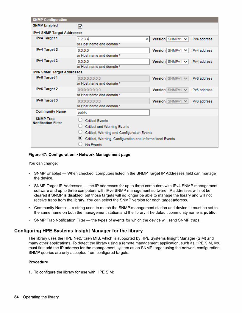
Figure 47: Configuration > Network Management page
You can change:
• SNMP Enabled — When checked, computers listed in the SNMP Target IP Addresses field can managethe device.
• SNMP Target IP Addresses — the IP addresses for up to three computers with IPv4 SNMP managementsoftware and up to three computers with IPv6 SNMP management software. IP addresses will not becleared if SNMP is disabled, but those targets will no longer be able to manage the library and will notreceive traps from the library. You can select the SNMP version for each target address.
• Community Name — a string used to match the SNMP management station and device. It must be set tothe same name on both the management station and the library. The default community name is public.
• SNMP Trap Notification Filter — the types of events for which the device will send SNMP traps.
Configuring HPE Systems Insight Manager for the libraryThe library uses the HPE NetCitizen MIB, which is supported by HPE Systems Insight Manager (SIM) andmany other applications. To detect the library using a remote management application, such as HPE SIM, youmust first add the IP address for the management system as an SNMP target using the network configuration.SNMP queries are only accepted from configured targets.
Procedure
1. To configure the library for use with HPE SIM:
84 Operating the library
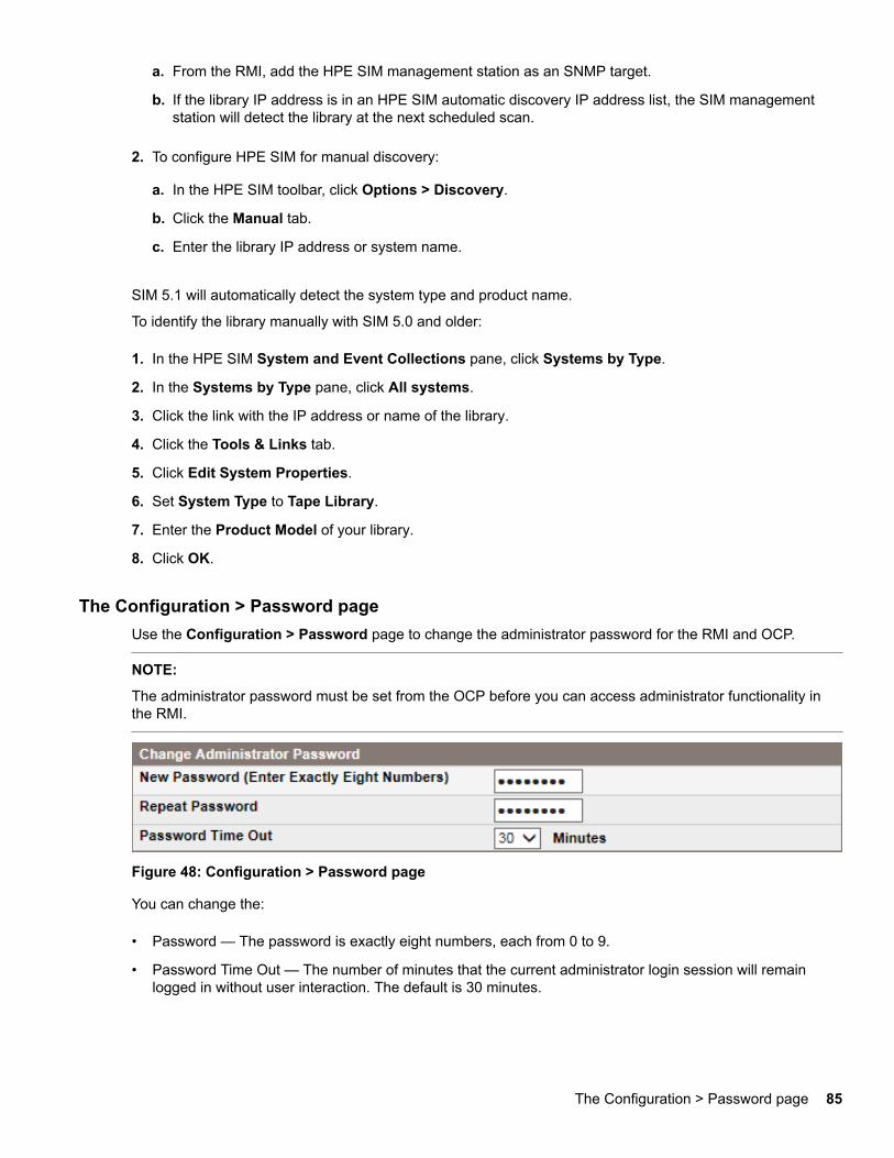
a. From the RMI, add the HPE SIM management station as an SNMP target.
b. If the library IP address is in an HPE SIM automatic discovery IP address list, the SIM managementstation will detect the library at the next scheduled scan.
2. To configure HPE SIM for manual discovery:
a. In the HPE SIM toolbar, click Options > Discovery.
b. Click the Manual tab.
c. Enter the library IP address or system name.
SIM 5.1 will automatically detect the system type and product name.
To identify the library manually with SIM 5.0 and older:
1. In the HPE SIM System and Event Collections pane, click Systems by Type.
2. In the Systems by Type pane, click All systems.
3. Click the link with the IP address or name of the library.
4. Click the Tools & Links tab.
5. Click Edit System Properties.
6. Set System Type to Tape Library.
7. Enter the Product Model of your library.
8. Click OK.
The Configuration > Password pageUse the Configuration > Password page to change the administrator password for the RMI and OCP.
NOTE:
The administrator password must be set from the OCP before you can access administrator functionality inthe RMI.
Figure 48: Configuration > Password page
You can change the:
• Password — The password is exactly eight numbers, each from 0 to 9.
• Password Time Out — The number of minutes that the current administrator login session will remainlogged in without user interaction. The default is 30 minutes.
The Configuration > Password page 85
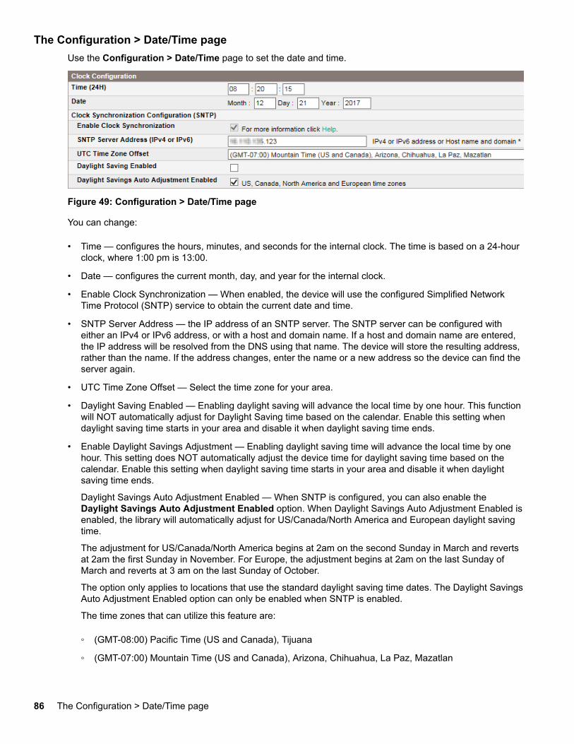
The Configuration > Date/Time pageUse the Configuration > Date/Time page to set the date and time.
Figure 49: Configuration > Date/Time page
You can change:
• Time — configures the hours, minutes, and seconds for the internal clock. The time is based on a 24-hourclock, where 1:00 pm is 13:00.
• Date — configures the current month, day, and year for the internal clock.
• Enable Clock Synchronization — When enabled, the device will use the configured Simplified NetworkTime Protocol (SNTP) service to obtain the current date and time.
• SNTP Server Address — the IP address of an SNTP server. The SNTP server can be configured witheither an IPv4 or IPv6 address, or with a host and domain name. If a host and domain name are entered,the IP address will be resolved from the DNS using that name. The device will store the resulting address,rather than the name. If the address changes, enter the name or a new address so the device can find theserver again.
• UTC Time Zone Offset — Select the time zone for your area.
• Daylight Saving Enabled — Enabling daylight saving will advance the local time by one hour. This functionwill NOT automatically adjust for Daylight Saving time based on the calendar. Enable this setting whendaylight saving time starts in your area and disable it when daylight saving time ends.
• Enable Daylight Savings Adjustment — Enabling daylight saving time will advance the local time by onehour. This setting does NOT automatically adjust the device time for daylight saving time based on thecalendar. Enable this setting when daylight saving time starts in your area and disable it when daylightsaving time ends.
Daylight Savings Auto Adjustment Enabled — When SNTP is configured, you can also enable theDaylight Savings Auto Adjustment Enabled option. When Daylight Savings Auto Adjustment Enabled isenabled, the library will automatically adjust for US/Canada/North America and European daylight savingtime.
The adjustment for US/Canada/North America begins at 2am on the second Sunday in March and revertsat 2am the first Sunday in November. For Europe, the adjustment begins at 2am on the last Sunday ofMarch and reverts at 3 am on the last Sunday of October.
The option only applies to locations that use the standard daylight saving time dates. The Daylight SavingsAuto Adjustment Enabled option can only be enabled when SNTP is enabled.
The time zones that can utilize this feature are:
◦ (GMT-08:00) Pacific Time (US and Canada), Tijuana
◦ (GMT-07:00) Mountain Time (US and Canada), Arizona, Chihuahua, La Paz, Mazatlan
86 The Configuration > Date/Time page
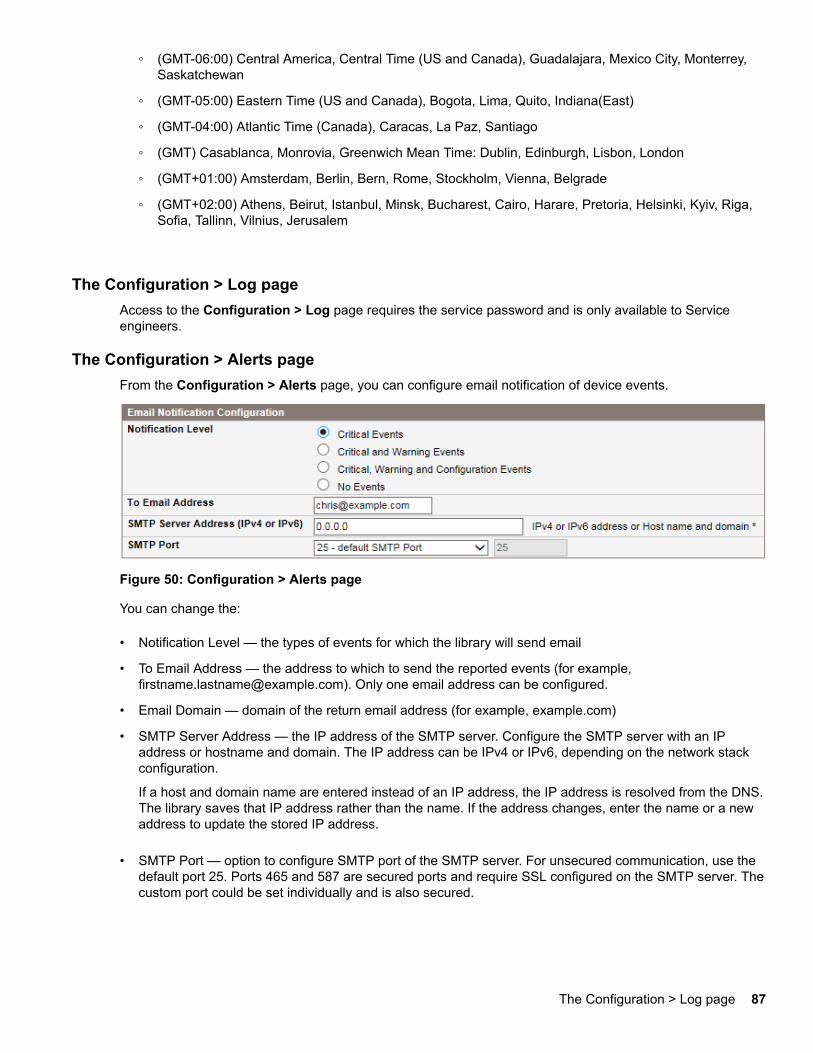
◦ (GMT-06:00) Central America, Central Time (US and Canada), Guadalajara, Mexico City, Monterrey,Saskatchewan
◦ (GMT-05:00) Eastern Time (US and Canada), Bogota, Lima, Quito, Indiana(East)
◦ (GMT-04:00) Atlantic Time (Canada), Caracas, La Paz, Santiago
◦ (GMT) Casablanca, Monrovia, Greenwich Mean Time: Dublin, Edinburgh, Lisbon, London
◦ (GMT+01:00) Amsterdam, Berlin, Bern, Rome, Stockholm, Vienna, Belgrade
◦ (GMT+02:00) Athens, Beirut, Istanbul, Minsk, Bucharest, Cairo, Harare, Pretoria, Helsinki, Kyiv, Riga,Sofia, Tallinn, Vilnius, Jerusalem
The Configuration > Log pageAccess to the Configuration > Log page requires the service password and is only available to Serviceengineers.
The Configuration > Alerts pageFrom the Configuration > Alerts page, you can configure email notification of device events.
Figure 50: Configuration > Alerts page
You can change the:
• Notification Level — the types of events for which the library will send email
• To Email Address — the address to which to send the reported events (for example,[email protected]). Only one email address can be configured.
• Email Domain — domain of the return email address (for example, example.com)
• SMTP Server Address — the IP address of the SMTP server. Configure the SMTP server with an IPaddress or hostname and domain. The IP address can be IPv4 or IPv6, depending on the network stackconfiguration.
If a host and domain name are entered instead of an IP address, the IP address is resolved from the DNS.The library saves that IP address rather than the name. If the address changes, enter the name or a newaddress to update the stored IP address.
• SMTP Port — option to configure SMTP port of the SMTP server. For unsecured communication, use thedefault port 25. Ports 465 and 587 are secured ports and require SSL configured on the SMTP server. Thecustom port could be set individually and is also secured.
The Configuration > Log page 87
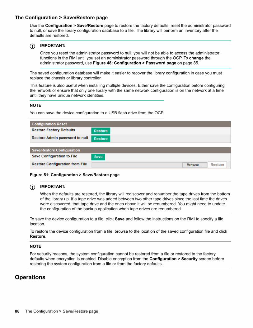
The Configuration > Save/Restore pageUse the Configuration > Save/Restore page to restore the factory defaults, reset the administrator passwordto null, or save the library configuration database to a file. The library will perform an inventory after thedefaults are restored.
IMPORTANT:
Once you reset the administrator password to null, you will not be able to access the administratorfunctions in the RMI until you set an administrator password through the OCP. To change theadministrator password, use Figure 48: Configuration > Password page on page 85.
The saved configuration database will make it easier to recover the library configuration in case you mustreplace the chassis or library controller.
This feature is also useful when installing multiple devices. Either save the configuration before configuringthe network or ensure that only one library with the same network configuration is on the network at a timeuntil they have unique network identities.
NOTE:
You can save the device configuration to a USB flash drive from the OCP.
Figure 51: Configuration > Save/Restore page
IMPORTANT:
When the defaults are restored, the library will rediscover and renumber the tape drives from the bottomof the library up. If a tape drive was added between two other tape drives since the last time the driveswere discovered, that tape drive and the ones above it will be renumbered. You might need to updatethe configuration of the backup application when tape drives are renumbered.
To save the device configuration to a file, click Save and follow the instructions on the RMI to specify a filelocation.
To restore the device configuration from a file, browse to the location of the saved configuration file and clickRestore.
NOTE:
For security reasons, the system configuration cannot be restored from a file or restored to the factorydefaults when encryption is enabled. Disable encryption from the Configuration > Security screen beforerestoring the system configuration from a file or from the factory defaults.
Operations
88 The Configuration > Save/Restore page
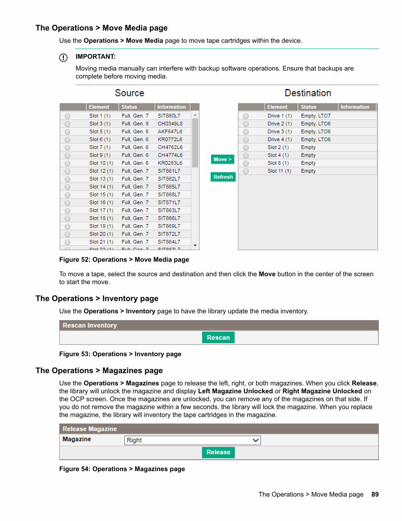
The Operations > Move Media pageUse the Operations > Move Media page to move tape cartridges within the device.
IMPORTANT:
Moving media manually can interfere with backup software operations. Ensure that backups arecomplete before moving media.
Figure 52: Operations > Move Media page
To move a tape, select the source and destination and then click the Move button in the center of the screento start the move.
The Operations > Inventory pageUse the Operations > Inventory page to have the library update the media inventory.
Figure 53: Operations > Inventory page
The Operations > Magazines pageUse the Operations > Magazines page to release the left, right, or both magazines. When you click Release,the library will unlock the magazine and display Left Magazine Unlocked or Right Magazine Unlocked onthe OCP screen. Once the magazines are unlocked, you can remove any of the magazines on that side. Ifyou do not remove the magazine within a few seconds, the library will lock the magazine. When you replacethe magazine, the library will inventory the tape cartridges in the magazine.
Figure 54: Operations > Magazines page
The Operations > Move Media page 89
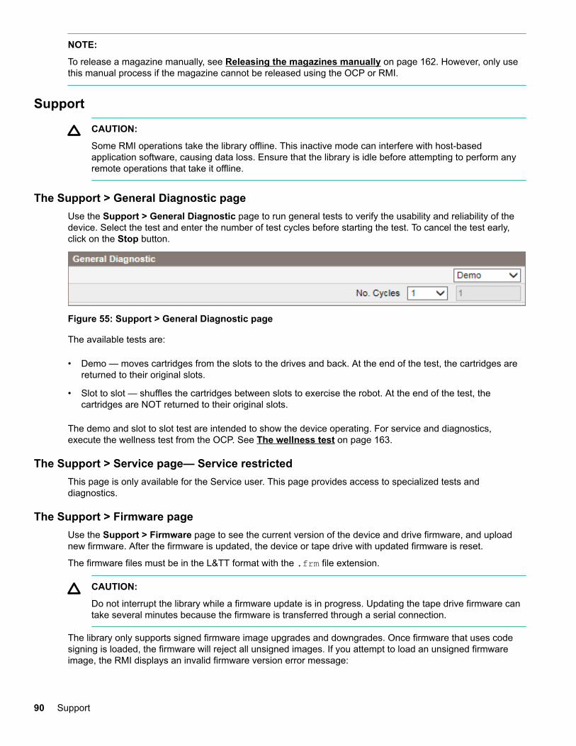
NOTE:
To release a magazine manually, see Releasing the magazines manually on page 162. However, only usethis manual process if the magazine cannot be released using the OCP or RMI.
Support
CAUTION:
Some RMI operations take the library offline. This inactive mode can interfere with host-basedapplication software, causing data loss. Ensure that the library is idle before attempting to perform anyremote operations that take it offline.
The Support > General Diagnostic pageUse the Support > General Diagnostic page to run general tests to verify the usability and reliability of thedevice. Select the test and enter the number of test cycles before starting the test. To cancel the test early,click on the Stop button.
Figure 55: Support > General Diagnostic page
The available tests are:
• Demo — moves cartridges from the slots to the drives and back. At the end of the test, the cartridges arereturned to their original slots.
• Slot to slot — shuffles the cartridges between slots to exercise the robot. At the end of the test, thecartridges are NOT returned to their original slots.
The demo and slot to slot test are intended to show the device operating. For service and diagnostics,execute the wellness test from the OCP. See The wellness test on page 163.
The Support > Service page— Service restrictedThis page is only available for the Service user. This page provides access to specialized tests anddiagnostics.
The Support > Firmware pageUse the Support > Firmware page to see the current version of the device and drive firmware, and uploadnew firmware. After the firmware is updated, the device or tape drive with updated firmware is reset.
The firmware files must be in the L&TT format with the .frm file extension.
CAUTION:
Do not interrupt the library while a firmware update is in progress. Updating the tape drive firmware cantake several minutes because the firmware is transferred through a serial connection.
The library only supports signed firmware image upgrades and downgrades. Once firmware that uses codesigning is loaded, the firmware will reject all unsigned images. If you attempt to load an unsigned firmwareimage, the RMI displays an invalid firmware version error message:
90 Support
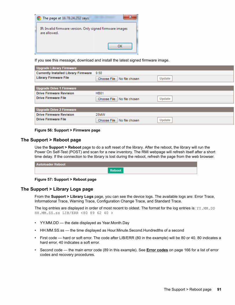
If you see this message, download and install the latest signed firmware image.
Figure 56: Support > Firmware page
The Support > Reboot pageUse the Support > Reboot page to do a soft reset of the library. After the reboot, the library will run thePower On Self-Test (POST) and scan for a new inventory. The RMI webpage will refresh itself after a shorttime delay. If the connection to the library is lost during the reboot, refresh the page from the web browser.
Figure 57: Support > Reboot page
The Support > Library Logs pageFrom the Support > Library Logs page, you can see the device logs. The available logs are: Error Trace,Informational Trace, Warning Trace, Configuration Change Trace, and Standard Trace.
The log entries are displayed in order of most recent to oldest. The format for the log entries is: YY.MM.DDHH.MM.SS.ss LIB/ERR <80 89 62 40 >
• YY.MM.DD — the date displayed as Year.Month.Day
• HH.MM.SS.ss — the time displayed as Hour.Minute.Second.Hundredths of a second
• First code — hard or soft error. The code after LIB/ERR (80 in the example) will be 80 or 40. 80 indicates ahard error, 40 indicates a soft error.
• Second code — the main error code (89 in this example). See Error codes on page 166 for a list of errorcodes and recovery procedures.
The Support > Reboot page 91
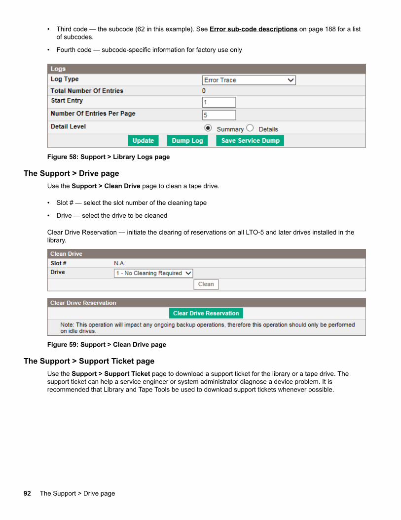
• Third code — the subcode (62 in this example). See Error sub-code descriptions on page 188 for a listof subcodes.
• Fourth code — subcode-specific information for factory use only
Figure 58: Support > Library Logs page
The Support > Drive pageUse the Support > Clean Drive page to clean a tape drive.
• Slot # — select the slot number of the cleaning tape
• Drive — select the drive to be cleaned
Clear Drive Reservation — initiate the clearing of reservations on all LTO-5 and later drives installed in thelibrary.
Figure 59: Support > Clean Drive page
The Support > Support Ticket pageUse the Support > Support Ticket page to download a support ticket for the library or a tape drive. Thesupport ticket can help a service engineer or system administrator diagnose a device problem. It isrecommended that Library and Tape Tools be used to download support tickets whenever possible.
92 The Support > Drive page
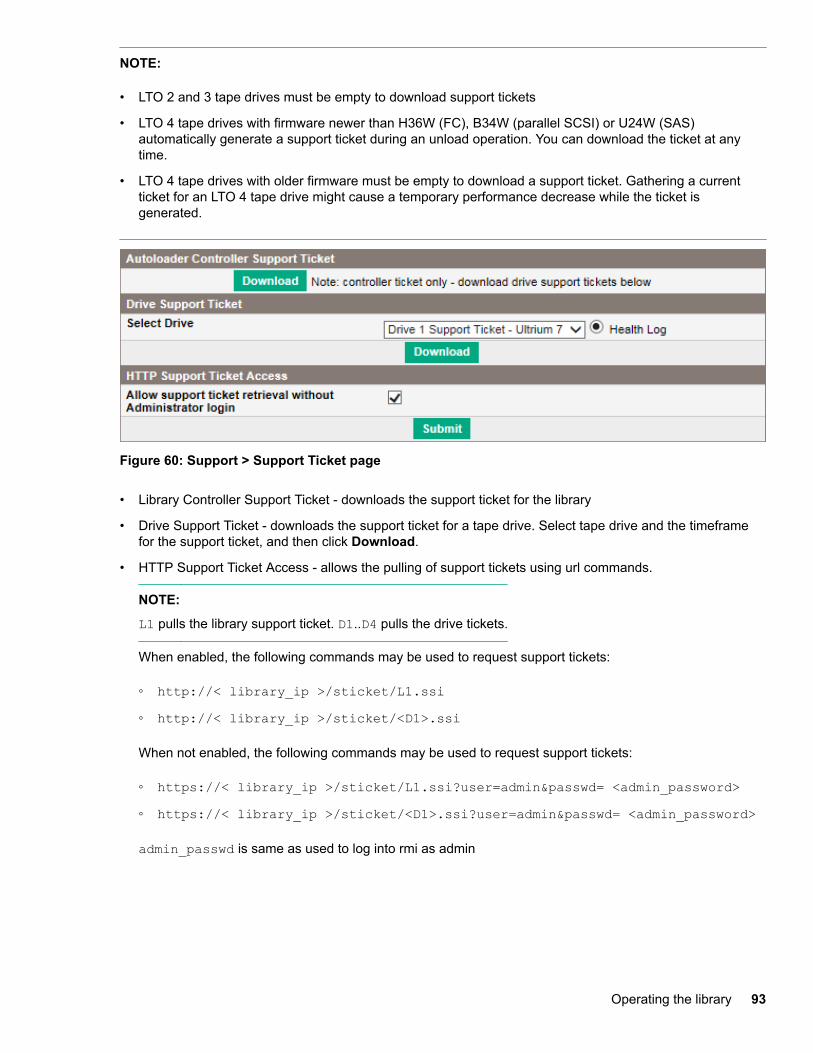
NOTE:
• LTO 2 and 3 tape drives must be empty to download support tickets
• LTO 4 tape drives with firmware newer than H36W (FC), B34W (parallel SCSI) or U24W (SAS)automatically generate a support ticket during an unload operation. You can download the ticket at anytime.
• LTO 4 tape drives with older firmware must be empty to download a support ticket. Gathering a currentticket for an LTO 4 tape drive might cause a temporary performance decrease while the ticket isgenerated.
Figure 60: Support > Support Ticket page
• Library Controller Support Ticket - downloads the support ticket for the library
• Drive Support Ticket - downloads the support ticket for a tape drive. Select tape drive and the timeframefor the support ticket, and then click Download.
• HTTP Support Ticket Access - allows the pulling of support tickets using url commands.
NOTE:
L1 pulls the library support ticket. D1..D4 pulls the drive tickets.
When enabled, the following commands may be used to request support tickets:
◦ http://< library_ip >/sticket/L1.ssi◦ http://< library_ip >/sticket/<D1>.ssi
When not enabled, the following commands may be used to request support tickets:
◦ https://< library_ip >/sticket/L1.ssi?user=admin&passwd= <admin_password>◦ https://< library_ip >/sticket/<D1>.ssi?user=admin&passwd= <admin_password>
admin_passwd is same as used to log into rmi as admin
Operating the library 93
Using the MSL2024 OCPThe OCP on the front of the library includes a 2-line by 16-character green backlit liquid crystal display (LCD),four function keys, and four LEDs. This panel provides everything you need to monitor the library status andcontrol its functions.
The following functions are available through the OCP:
• Unlocking the mailslot (Unlock Mailslot) on page 98
• Status/Information on page 99
◦ Viewing cartridge inventory (Status/Information > Inventory) on page 99
◦ Viewing library information (Status/Information> Library Information) on page 101
◦ Viewing drive information (Status/Information > Drive Information) on page 102
◦ Viewing component status (Status/Information > Component Status) on page 102
◦ Viewing network information (Status/Information > Network Information) on page 103
• Configuring the library on page 103
◦ Configuring logical libraries (Status/Information > Set Logical Libraries) on page 104
◦ Changing the administrator password (Configuration > Change Admin Password) on page 104
◦ Setting the number of reserved slots (Configuration > Set Reserved Slot Count) on page 105
◦ Configuring the mailslot (Configuration > Configure Mailslot) on page 105
◦ Configuring the bar code reporting format (Configuration > Barcode Format Reporting) on page105
◦ Changing the SCSI address — parallel SCSI drives (Configuration> Change Drive) on page 106
◦ Setting the master drive (Configuration > Set Master Drive) on page 107
◦ Setting behaviors (Configuration > Library behavior) on page 108
◦ Setting the date and time (Configuration > Library Date/Time) on page 109
◦ Configuring IPv4 network settings (Configuration > Configure Network Settings) on page 110
◦ Configuring automatic cleaning (Configuration > Configure Auto Cleaning) on page 110
◦ Restoring factory defaults (Configuration > Restore Defaults) on page 111
◦ Saving the library configuration (Configuration> Save/Restore Configuration) on page 112
• Accessing the operations functions on page 113
◦ Unlocking, removing, and replacing magazines (Operations > Unlock Left or Right Magazine) onpage 113
◦ Cleaning a tape drive (Operations > Clean Drive) on page 114
◦ Moving tapes in the library (Operations > Move Tape) on page 115
◦ Updating tape cartridge inventory (Operations > Perform Inventory) on page 116
94 Using the MSL2024 OCP
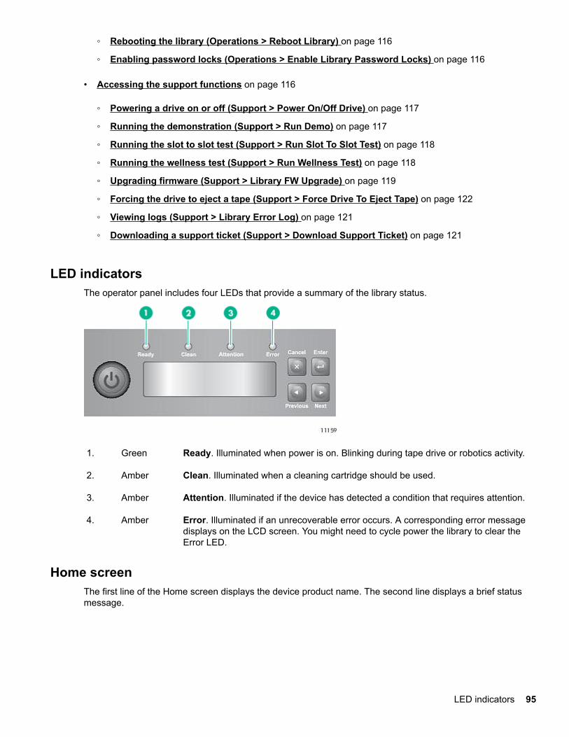
◦ Rebooting the library (Operations > Reboot Library) on page 116
◦ Enabling password locks (Operations > Enable Library Password Locks) on page 116
• Accessing the support functions on page 116
◦ Powering a drive on or off (Support > Power On/Off Drive) on page 117
◦ Running the demonstration (Support > Run Demo) on page 117
◦ Running the slot to slot test (Support > Run Slot To Slot Test) on page 118
◦ Running the wellness test (Support > Run Wellness Test) on page 118
◦ Upgrading firmware (Support > Library FW Upgrade) on page 119
◦ Forcing the drive to eject a tape (Support > Force Drive To Eject Tape) on page 122
◦ Viewing logs (Support > Library Error Log) on page 121
◦ Downloading a support ticket (Support > Download Support Ticket) on page 121
LED indicatorsThe operator panel includes four LEDs that provide a summary of the library status.
1. Green Ready. Illuminated when power is on. Blinking during tape drive or robotics activity.
2. Amber Clean. Illuminated when a cleaning cartridge should be used.
3. Amber Attention. Illuminated if the device has detected a condition that requires attention.
4. Amber Error. Illuminated if an unrecoverable error occurs. A corresponding error messagedisplays on the LCD screen. You might need to cycle power the library to clear theError LED.
Home screenThe first line of the Home screen displays the device product name. The second line displays a brief statusmessage.
LED indicators 95
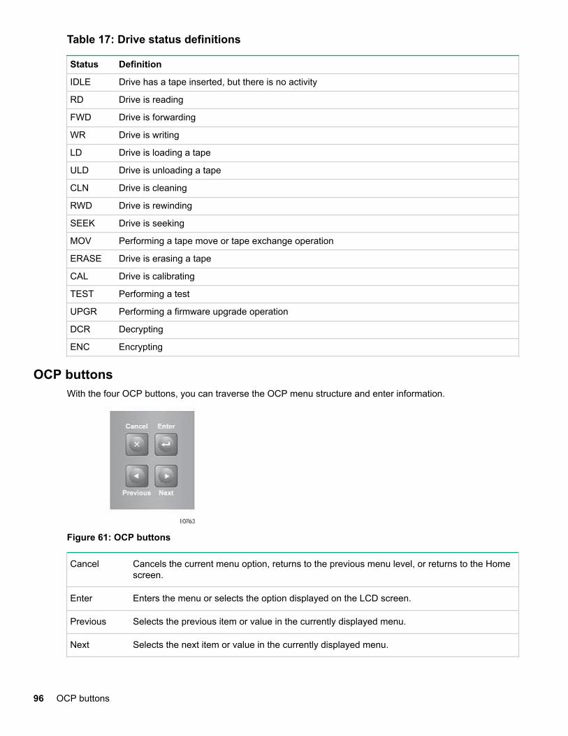
Table 17: Drive status definitions
Status Definition
IDLE Drive has a tape inserted, but there is no activity
RD Drive is reading
FWD Drive is forwarding
WR Drive is writing
LD Drive is loading a tape
ULD Drive is unloading a tape
CLN Drive is cleaning
RWD Drive is rewinding
SEEK Drive is seeking
MOV Performing a tape move or tape exchange operation
ERASE Drive is erasing a tape
CAL Drive is calibrating
TEST Performing a test
UPGR Performing a firmware upgrade operation
DCR Decrypting
ENC Encrypting
OCP buttonsWith the four OCP buttons, you can traverse the OCP menu structure and enter information.
Figure 61: OCP buttons
Cancel Cancels the current menu option, returns to the previous menu level, or returns to the Homescreen.
Enter Enters the menu or selects the option displayed on the LCD screen.
Previous Selects the previous item or value in the currently displayed menu.
Next Selects the next item or value in the currently displayed menu.
96 OCP buttons
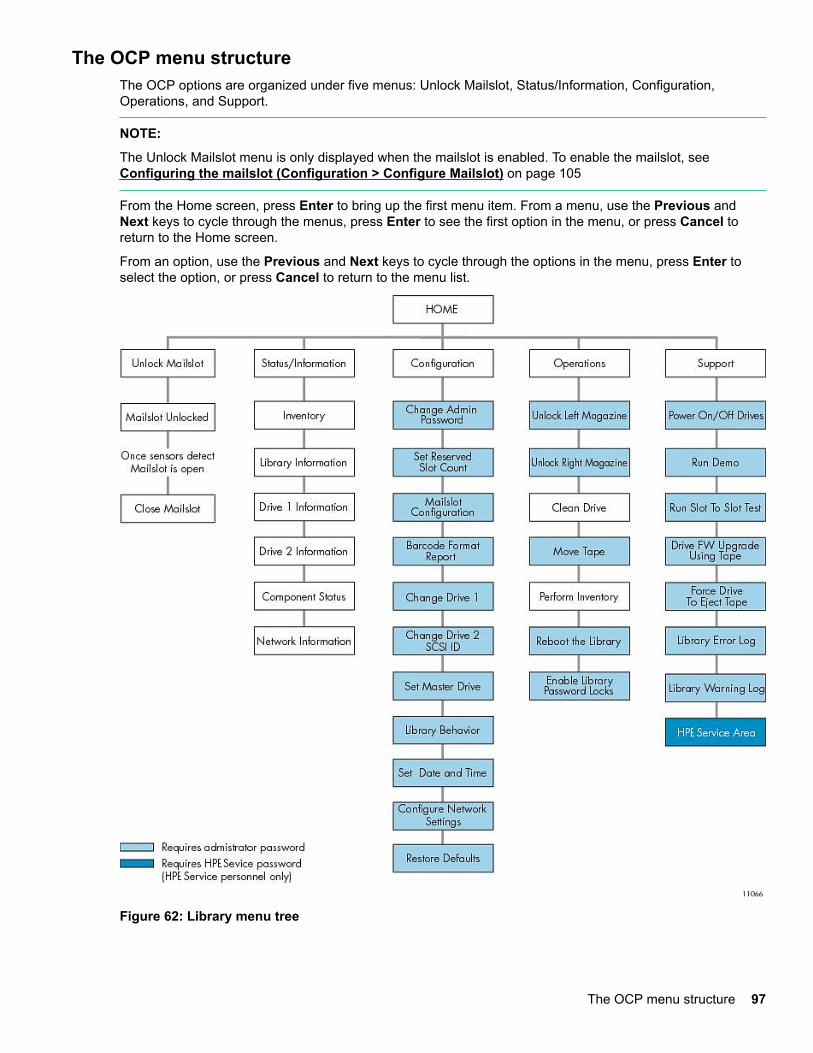
The OCP menu structureThe OCP options are organized under five menus: Unlock Mailslot, Status/Information, Configuration,Operations, and Support.
NOTE:
The Unlock Mailslot menu is only displayed when the mailslot is enabled. To enable the mailslot, see Configuring the mailslot (Configuration > Configure Mailslot) on page 105
From the Home screen, press Enter to bring up the first menu item. From a menu, use the Previous andNext keys to cycle through the menus, press Enter to see the first option in the menu, or press Cancel toreturn to the Home screen.
From an option, use the Previous and Next keys to cycle through the options in the menu, press Enter toselect the option, or press Cancel to return to the menu list.
Figure 62: Library menu tree
The OCP menu structure 97
The administrator password accesses all of the available functionality, except for the Service Area. A userwithout the administrator password has access to the Unlock Mailslot and Status/Information menus.
Entering the administrator password
TIP:
By default, the administrator password is unset; all of the digits are null. Set the administrator passwordfrom the OCP to protect the administrator functions on the OCP and enable the administrator functionsin the RMI.
Options that require a password will prompt for a password before allowing access to the restricted screens.Once entered, the administrator password does not need to be entered again unless there is no user activityfor five minutes or the password lock is enabled.
The number 1 should be flashing. To enter the password, do the following:
Procedure
1. From the OCP, press Next to scroll to the first number of the password.
2. Press Enter. The number you selected is replaced with an asterisk (*), and the cursor proceeds to the nexttext box.
3. Repeat steps 1 and 2 until you have entered all eight numbers. After the last number has been entered,the screen continues to the restricted area.
NOTE:
If you forget the administrator password, you cannot enter a new password. Call your customer servicerepresentative.
Unlocking the mailslot (Unlock Mailslot)The mailslot in the left magazine is used only with host system software that supports this feature. Themailslot feature allows you to insert or remove a single tape without removing the entire magazine. Thebenefit of using a mailslot is that the device will not inventory the rest of the slots in the magazine so thedevice can return to service sooner. The mailslot is in the left magazine.
NOTE:
The Unlock Mailslot menu is only displayed when the mailslot is enabled. To enable the mailslot, see Configuring the mailslot (Configuration > Configure Mailslot) on page 105
Procedure
1. From the Home screen, press Next until the screen displays Unlock Mailslot. Press Enter to select.
2. The mailslot ejects automatically. Pull the mailslot out to access the tape.
3. The screen displays Close Mailslot.
4. Remove the tape cartridge from the mailslot and insert a different tape cartridge.
5. Push the magazine back into the library.
98 Entering the administrator password
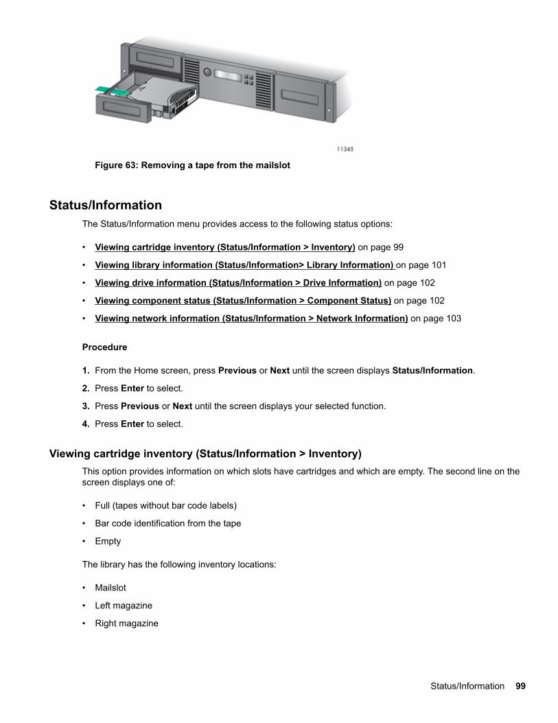
Figure 63: Removing a tape from the mailslot
Status/InformationThe Status/Information menu provides access to the following status options:
• Viewing cartridge inventory (Status/Information > Inventory) on page 99
• Viewing library information (Status/Information> Library Information) on page 101
• Viewing drive information (Status/Information > Drive Information) on page 102
• Viewing component status (Status/Information > Component Status) on page 102
• Viewing network information (Status/Information > Network Information) on page 103
Procedure
1. From the Home screen, press Previous or Next until the screen displays Status/Information.
2. Press Enter to select.
3. Press Previous or Next until the screen displays your selected function.
4. Press Enter to select.
Viewing cartridge inventory (Status/Information > Inventory)This option provides information on which slots have cartridges and which are empty. The second line on thescreen displays one of:
• Full (tapes without bar code labels)
• Bar code identification from the tape
• Empty
The library has the following inventory locations:
• Mailslot
• Left magazine
• Right magazine
Status/Information 99
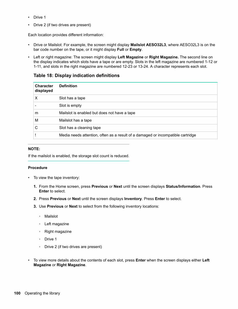
• Drive 1
• Drive 2 (if two drives are present)
Each location provides different information:
• Drive or Mailslot: For example, the screen might display Mailslot AESO32L3, where AESO32L3 is on thebar code number on the tape, or it might display Full or Empty.
• Left or right magazine: The screen might display Left Magazine or Right Magazine. The second line onthe display indicates which slots have a tape or are empty. Slots in the left magazine are numbered 1-12 or1-11, and slots in the right magazine are numbered 12-23 or 13-24. A character represents each slot.
Table 18: Display indication definitions
Characterdisplayed
Definition
X Slot has a tape
- Slot is empty
m Mailslot is enabled but does not have a tape
M Mailslot has a tape
C Slot has a cleaning tape
! Media needs attention, often as a result of a damaged or incompatible cartridge
NOTE:
If the mailslot is enabled, the storage slot count is reduced.
Procedure
• To view the tape inventory:
1. From the Home screen, press Previous or Next until the screen displays Status/Information. PressEnter to select.
2. Press Previous or Next until the screen displays Inventory. Press Enter to select.
3. Use Previous or Next to select from the following inventory locations:
◦ Mailslot
◦ Left magazine
◦ Right magazine
◦ Drive 1
◦ Drive 2 (if two drives are present)
• To view more details about the contents of each slot, press Enter when the screen displays either LeftMagazine or Right Magazine.
100 Operating the library
◦ Mailslot
◦ Left magazine
◦ Right magazine
◦ Drive 1
◦ Drive 2 (if two drives are present)
• To view the inventory of a magazine, press Enter when the OCP displays Left or Right Magazine.
The OCP will display the contents of the lowest numbered slot in the magazine. The display will show thetape bar code number, Full, or Empty.
1. Use Previous or Next to scroll through the remaining slots in the magazine. Press Cancel to chooseanother inventory location.
• To view the inventory of a tape drive, press Previous or Next until the screen displays Drive 1, or Drive 2.The display will show the tape bar code number, Full, or Empty. Press Enter to view the source of thetape loaded in the drive. For example, Drive 1 Tape Source = Slot 2, indicates that the tape in Drive 1was loaded from slot 2.
Viewing library information (Status/Information> Library Information)
Procedure
1. From the Home screen, press Previous or Next until the screen displays Status/Information. PressEnter to select.
2. Press Previous or Next until the screen displays Library Information . Press Enter to select.
3. By using Previous or Next, you can select from the following information screens:
• Library Time
• Firmware rev.
• Product ID
• Serial number
• SCSI ID and LUN (SCSI devices only)
• Slots and Mailslots
• Master drive
• Odometer
• Power On Time
• WWide Node Name for the FC node to which the Library is connected. (Fibre Channel only)
Viewing library information (Status/Information> Library Information) 101
Viewing drive information (Status/Information > Drive Information)
Procedure
1. From the Home screen, press Previous or Next until the screen displays Status/Information. PressEnter to select.
2. Press Previous or Next until the screen displays Drive 1 Information or Drive 2 Information. PressEnter to select.
3. By using Previous or Next, you can select from the following information screens:
• Serial number
• Drive type
• Firmware revision
• SCSI ID (parallel SCSI tape drives only)
For a Fibre Channel tape drive, you can also select from the following information screens:
• The WWide Node Name for the FC node to which the tape drive is connected.
• The WWide Port Name and Port Type for Port A.
• The WWide Port Name and Port Type for Port B.
World Wide names are assigned automatically; they cannot be configured.
Viewing component status (Status/Information > Component Status)
Procedure
1. From the Home screen, press Previous or Next until the screen displays Status/Information. PressEnter to select.
2. Press Previous or Next until the screen displays Component Status. Press Enter to select.
3. By using Previous or Next, you can select from the following information screens:
• Drive activity
• Library status
• Drives status
• Fan status
The second line of the screen will display one of the following:
• Good — the component is operating normally.
• Warning — the component might have an issue that should be addressed. The Library is functional.
102 Viewing drive information (Status/Information > Drive Information)
• Critical — the component has an error condition that should be addressed. The Library might not befully functional.
• Failed — the component has a known failure and should be replaced.
Viewing network information (Status/Information > Network Information)
Procedure
1. From the Home screen, press Previous or Next until the screen displays Status/Information. PressEnter to select.
2. Press Previous or Next until the screen displays Network Information. Press Enter to select.
3. Press Previous or Next to access the following information:
• IPv4 Network Enabled or Disabled
• IPv6 Network Enabled or Disabled
• Host Name
• Domain Name
• MAC Address
4. For IPv4 Network or IPv6 Network, press Enter and then use Previous or Next to access the networkaddresses and configuration.
Configuring the libraryConfigure the library from the Configuration menu.
Procedure
1. From the Home screen, press Previous or Next until the screen displays Configuration.
2. Press Enter to select.
3. Press Previous or Next until the screen displays your selected function.
• Configuring logical libraries (Status/Information > Set Logical Libraries) on page 104
• Changing the administrator password (Configuration > Change Admin Password) on page 104
• Setting the number of reserved slots (Configuration > Set Reserved Slot Count) on page 105
• Configuring the mailslot (Configuration > Configure Mailslot) on page 105
• Configuring the bar code reporting format (Configuration > Barcode Format Reporting) on page105
• Changing the SCSI address — parallel SCSI drives (Configuration> Change Drive) on page 106
• Changing the drive configuration — Fibre Channel drives (Configuration> Change Drive) onpage 106
• Setting the master drive (Configuration > Set Master Drive) on page 107
Viewing network information (Status/Information > Network Information) 103
• Setting behaviors (Configuration > Library behavior) on page 108
• Setting the date and time (Configuration > Library Date/Time) on page 109
• Configuring IPv4 network settings (Configuration > Configure Network Settings) on page 110
• Configuring automatic cleaning (Configuration > Configure Auto Cleaning) on page 110
• Restoring factory defaults (Configuration > Restore Defaults) on page 111
• Saving the library configuration (Configuration> Save/Restore Configuration) on page 112
4. Press Enter to select.
Configuring logical libraries (Status/Information > Set Logical Libraries)Use Set Logical Libraries to configure a two-drive tape library into one or two logical libraries. Access to thisfeature requires the administrator password. For more information about logical libraries, see Logicallibraries on page 21.
Procedure
1. From the Home screen, press Previous or Next until the screen displays Configuration. Press Enter toselect.
2. Press Previous or Next until the screen displays Set Logical Libraries. Press Enter to select.
3. Enter the administrator password if prompted.
4. Press Previous or Next to scroll through the display until the desired number of logical libraries isdisplayed, then press Enter.
Changing the administrator password (Configuration > Change Admin Password)Use Change Admin Password to set or change the administrator password. Once the administratorpassword is set, you must know the administrator password or the service password to change theadministrator password. Passwords consist of exactly eight numbers each between the values of 0 and 9.
Screens that require a password prompt for the password before allowing access to the restricted areas.Once entered, the administrator password does not have to be entered a second time unless there is no useractivity for five minutes. Enter the administrator password if you are prompted to do so.
NOTE:
If you forget the administrator password, you cannot enter a new password. Call your customer servicerepresentative.
Procedure
1. From the Home screen, press Previous or Next until the screen displays Configuration. Press Enter toselect.
2. Press Previous or Next until the screen displays Change Admin Password. Press Enter to select.
104 Configuring logical libraries (Status/Information > Set Logical Libraries)
3. The first number is flashing. Press Previous or Next to change the value of the flashing number. When theflashing number shows the desired value, press Enter to select.
4. The screen displays the second number flashing. Repeat Step 3 until you have entered all eightcharacters. Press Enter to select. After the last number has been entered, the password has been set tothe new password.
Setting the number of reserved slots (Configuration > Set Reserved Slot Count)You can access reserved slots from the RMI and the OCP, but the reserved slots are invisible to the host andbackup software. For example, you might keep a cleaning cartridge in a reserved slot if your backup softwaredoes not manage the cleaning process.
You can reserve up to 22 slots.
Prerequisites
Access to this feature requires the administrator password.
Procedure
1. From the Home screen, press Previous or Next until the screen displays Configuration. Press Enter toselect.
2. Press Previous or Next until the screen displays Set Reserved Slot Count. Press Enter to select.
3. Enter the administrator password if prompted.
4. Press Previous or Next to scroll through the display until the desired number of slots is displayed, thenpress Enter.
Configuring the mailslot (Configuration > Configure Mailslot)The mailslot is a single slot at the front of the left magazine that you can access without removing the wholemagazine. Loading a tape through the mailslot is faster than opening the magazine because the device doesnot need to inventory the rest of the magazine slots when you use the mailslot. Also, the device can continueto function when the mailslot is open. Access to this feature requires the administrator password.
Procedure
1. From the Home screen, press Previous or Next until the screen displays Configuration. Press Enter toselect.
2. Press Previous or Next until the screen displays Configure Mailslot. Press Enter to select.
3. Enter the administrator password if prompted.
4. The screen displays either Mailslot Enabled or Mailslot Disabled.
5. Press Previous or Next until the screen displays Disable Mailslot? or Enable Mailslot?. Press Enterwhen the correct action is displayed.
Configuring the bar code reporting format (Configuration > Barcode Format Reporting)You can configure how the tape bar code is displayed in the OCP and RMI, and how it is reported to the hostsoftware. You can configure the number of characters to display and whether to justify the numbers to the leftor right. For example, when reporting only six characters of the bar code label 12345678, if alignment is left,the device will report 123456. If alignment is right, the device will report 345678. The maximum length is 15
Setting the number of reserved slots (Configuration > Set Reserved SlotCount) 105
characters. The default configuration is 8 Left. The OCP displays bar code labels longer than eight charactersin an abbreviated form.
Prerequisites
The administrator password.
Procedure
1. From the Home screen, press Previous or Next until the screen displays Configuration. Press Enter toselect.
2. Press Previous or Next until the screen displays Barcode Format Reporting. Press Enter to select.
3. Press Previous or Next until the screen displays either Display Format or Host Format. The second linedisplays the number of characters and the current format. To change the current format, press Enter toselect either Display or Host. An example of the screen display is # of characters 8.
4. Press Previous or Next until the desired number of characters is listed. Press Enter to select.
5. The screen displays either Alignment Left or Alignment Right. Use Previous or Next to toggle betweenthe two choices. Press Enter to select the correct alignment.
Changing the SCSI address — parallel SCSI drives (Configuration> Change Drive)
CAUTION:
If you change the SCSI ID, you might need to cycle power on the host server and reconfigure yourbackup software before you can use the device.
This option changes the SCSI address of a tape drive. The tape drive logical unit number (LUN) will alwaysbe LUN 0 on the SCSI address. The library SCSI address will be the same as the master drive, but will useLUN 1. Access to this feature requires the administrator password.
Procedure
1. From the Home screen, press Previous or Next until the screen displays Configuration. Press Enter toselect.
2. Press Previous or Next until the screen displays Change Drive 1 or Change Drive 2. Press Enter toselect.
3. Enter the administrator password if prompted.
4. The screen displays the current SCSI ID. Press Previous or Next to change the SCSI ID number. PressEnter to select.
An example of the screen display is Drive 1 SCSI ID 6 .
Changing the drive configuration — Fibre Channel drives (Configuration> Change Drive)This option allows you to configure the FC ports for your tape drive.
Each drive has two ports, A and B.
106 Changing the SCSI address — parallel SCSI drives (Configuration>Change Drive)
NOTE:
Hewlett Packard Enterprise recommends that you cable Port A only and that you configure Port B for AutoDetect on Fibre Speedand Port Type.
Only cable Port A and configure Port B for Auto Detect on Fibre Speed and Port Type.
Procedure
1. From the Home screen, press Previous or Next until the screen displays Configuration. Press Enter toselect.
2. Press Previous or Next until the screen displays Change Drive 1. Press Enter to select.
3. Enter the administrator password if prompted.
4. The screen displays Port A. Press Enter to select and display Fibre Speed.
5. Press Enter to display Set Fibre Speed. Press Previous or Next to toggle through the speed settings(Auto Detect, 1 Gb/s, 2 Gb/s, 4 Gb/s, or 8 Gb/s). Only speeds supported by the drive are listed. PressEnter to select the required speed.
6. The screen displays Port Type. Press Enter to display Set Port Type. Press Previous or Next to togglethrough the port types (Fabric (N), Loop (NL), or Auto Detect). Press Enter to select the required porttype.
7. If you selected Fabric (N) or Auto Detect, configuration is now complete; go to step 9. If you selectedLoop (NL), Set Port Loop Mode is displayed. Press Previous or Next to toggle through the loop modes(Soft, Hard, or Hard Auto Select). Press Enter to select the required loop mode.
8. If you selected Soft or Hard Auto Select, configuration is now complete; go to step 9. If you selectedHard, Set ALPA is displayed with the first number flashing. Press Previous or Next until the flashingnumber reads correctly. Press Enter to move to the next number. Repeat this step until all numbers inthe address are correct. Press Enter.
9. Press Enter to save the settings and reset the port.
The screen displays Port B.
10. Press Enter to select and display Fibre Speed. Select Auto Detect. Press Enter.
11. Press Enter to select and display Port Type. Select Auto Detect. Press Enter.
Setting the master drive (Configuration > Set Master Drive)
CAUTION:
If you change the SCSI ID, you might need to cycle power on the host server and reconfigure yourbackup software before you can use the device.
Procedure
1. From the Home screen, press Previous or Next until the screen displays Configuration. Press Enter toselect.
2. Press Previous or Next until the screen displays Set Master Drive. Press Enter to select.
3. Enter the administrator password if prompted.
Setting the master drive (Configuration > Set Master Drive) 107
4. Press Previous or Next until the screen displays either Master Drive Drive 1 or Master Drive Drive 2.
5. Press Enter to select the displayed configuration. The screen displays either Drive 1 Set to Master, orDrive 2 Set to Master, and the Ready LED blinks.
Setting behaviors (Configuration > Library behavior)The library supports three behavior modes: Random, Sequential, and Automatic. The library automaticallydetects the required mode from the series of SCSI commands it receives; however, you can also change themode. Choose the operating mode based on the capabilities of the software controlling the tape cartridges.
The library mode can be set independently for each logical library.
Random mode: In Random mode, the device does not automatically load tapes into the tape drive; it waitsfor commands from the software or operator to load and unload tapes. Random mode is used with a fullfeatured or a robotics-aware backup application and is the most common mode of operation. Your backupsoftware must support robotics, which might require an additional software module.
Sequential mode: In Sequential mode, the device automatically loads and unloads tapes from the drive.Sequential mode is used when the backup software is NOT robotics-aware or was designed for standalonedrives only.
In Sequential mode, the library will only use the lowest-numbered tape drive.
The operator begins the sequence by loading the desired tape into the tape drive. When a tape is unloadedfor any reason, the device automatically removes the tape from the drive, returns it to its original slot, thenloads the tape from the next available higher numbered slot.
To determine how you want tapes loaded into the tape drive while in Sequential mode, set the Loop andAutoload options.
• When Autoload mode is set, the device automatically loads the cartridge from the lowest-numbered fullslot into the tape drive. It then follows standard sequential operation. After configuring Autoload mode, youmust do one of the following for Autoload mode to take effect:
◦ Power cycle the device from the front panel.
◦ Reboot the device from the RMI Support > Reboot screen.
◦ Move the lowest-numbered cartridge to the drive before starting the backup application. If the mailslotis enabled, the lowest cartridge location will be in the mailslot.
• When Loop mode is on, the original first cartridge in the sequence is reloaded after the device has cycledthrough all available cartridges. If Loop mode is off and the last cartridge has been unloaded, the devicestops loading cartridges until you load another manually.
CAUTION:
Use caution when choosing Loop mode because it makes it possible to overwrite data on previouslywritten cartridges.
When a library is partitioned into logical libraries, each logical library operates as an independent library.Thus, the library only loads tapes from the slots associated with one logical library into the tape driveassociated with that logical library; it will not load tapes from slots associated with another logical library.
Automatic mode: In Automatic mode, the device switches from Sequential mode into Random mode when itreceives certain SCSI commands. Automatic mode is the default setting.
108 Setting behaviors (Configuration > Library behavior)
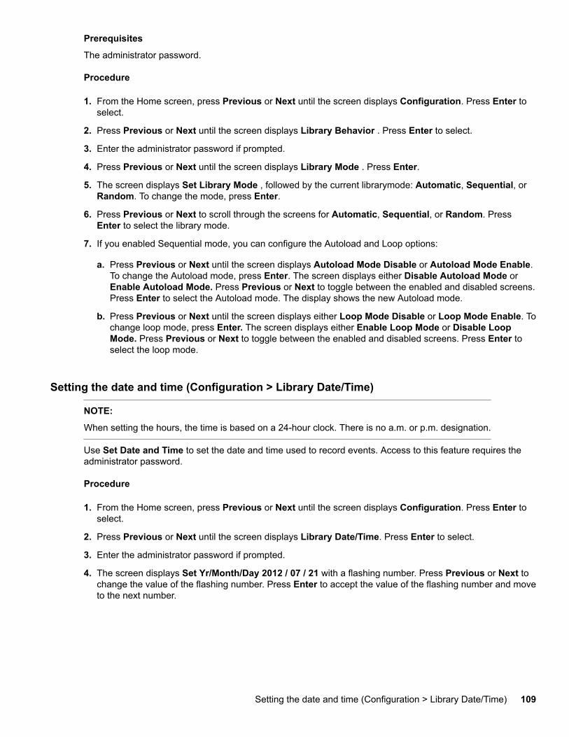
Prerequisites
The administrator password.
Procedure
1. From the Home screen, press Previous or Next until the screen displays Configuration. Press Enter toselect.
2. Press Previous or Next until the screen displays Library Behavior . Press Enter to select.
3. Enter the administrator password if prompted.
4. Press Previous or Next until the screen displays Library Mode . Press Enter.
5. The screen displays Set Library Mode , followed by the current librarymode: Automatic, Sequential, orRandom. To change the mode, press Enter.
6. Press Previous or Next to scroll through the screens for Automatic, Sequential, or Random. PressEnter to select the library mode.
7. If you enabled Sequential mode, you can configure the Autoload and Loop options:
a. Press Previous or Next until the screen displays Autoload Mode Disable or Autoload Mode Enable.To change the Autoload mode, press Enter. The screen displays either Disable Autoload Mode orEnable Autoload Mode. Press Previous or Next to toggle between the enabled and disabled screens.Press Enter to select the Autoload mode. The display shows the new Autoload mode.
b. Press Previous or Next until the screen displays either Loop Mode Disable or Loop Mode Enable. Tochange loop mode, press Enter. The screen displays either Enable Loop Mode or Disable LoopMode. Press Previous or Next to toggle between the enabled and disabled screens. Press Enter toselect the loop mode.
Setting the date and time (Configuration > Library Date/Time)
NOTE:
When setting the hours, the time is based on a 24-hour clock. There is no a.m. or p.m. designation.
Use Set Date and Time to set the date and time used to record events. Access to this feature requires theadministrator password.
Procedure
1. From the Home screen, press Previous or Next until the screen displays Configuration. Press Enter toselect.
2. Press Previous or Next until the screen displays Library Date/Time. Press Enter to select.
3. Enter the administrator password if prompted.
4. The screen displays Set Yr/Month/Day 2012 / 07 / 21 with a flashing number. Press Previous or Next tochange the value of the flashing number. Press Enter to accept the value of the flashing number and moveto the next number.
Setting the date and time (Configuration > Library Date/Time) 109
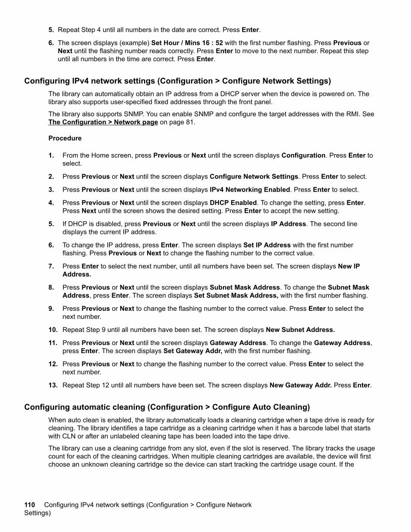
5. Repeat Step 4 until all numbers in the date are correct. Press Enter.
6. The screen displays (example) Set Hour / Mins 16 : 52 with the first number flashing. Press Previous orNext until the flashing number reads correctly. Press Enter to move to the next number. Repeat this stepuntil all numbers in the time are correct. Press Enter.
Configuring IPv4 network settings (Configuration > Configure Network Settings)The library can automatically obtain an IP address from a DHCP server when the device is powered on. Thelibrary also supports user-specified fixed addresses through the front panel.
The library also supports SNMP. You can enable SNMP and configure the target addresses with the RMI. See The Configuration > Network page on page 81.
Procedure
1. From the Home screen, press Previous or Next until the screen displays Configuration. Press Enter toselect.
2. Press Previous or Next until the screen displays Configure Network Settings. Press Enter to select.
3. Press Previous or Next until the screen displays IPv4 Networking Enabled. Press Enter to select.
4. Press Previous or Next until the screen displays DHCP Enabled. To change the setting, press Enter.Press Next until the screen shows the desired setting. Press Enter to accept the new setting.
5. If DHCP is disabled, press Previous or Next until the screen displays IP Address. The second linedisplays the current IP address.
6. To change the IP address, press Enter. The screen displays Set IP Address with the first numberflashing. Press Previous or Next to change the flashing number to the correct value.
7. Press Enter to select the next number, until all numbers have been set. The screen displays New IPAddress.
8. Press Previous or Next until the screen displays Subnet Mask Address. To change the Subnet MaskAddress, press Enter. The screen displays Set Subnet Mask Address, with the first number flashing.
9. Press Previous or Next to change the flashing number to the correct value. Press Enter to select thenext number.
10. Repeat Step 9 until all numbers have been set. The screen displays New Subnet Address.
11. Press Previous or Next until the screen displays Gateway Address. To change the Gateway Address,press Enter. The screen displays Set Gateway Addr, with the first number flashing.
12. Press Previous or Next to change the flashing number to the correct value. Press Enter to select thenext number.
13. Repeat Step 12 until all numbers have been set. The screen displays New Gateway Addr. Press Enter.
Configuring automatic cleaning (Configuration > Configure Auto Cleaning)When auto clean is enabled, the library automatically loads a cleaning cartridge when a tape drive is ready forcleaning. The library identifies a tape cartridge as a cleaning cartridge when it has a barcode label that startswith CLN or after an unlabeled cleaning tape has been loaded into the tape drive.
The library can use a cleaning cartridge from any slot, even if the slot is reserved. The library tracks the usagecount for each of the cleaning cartridges. When multiple cleaning cartridges are available, the device will firstchoose an unknown cleaning cartridge so the device can start tracking the cartridge usage count. If the
110 Configuring IPv4 network settings (Configuration > Configure NetworkSettings)
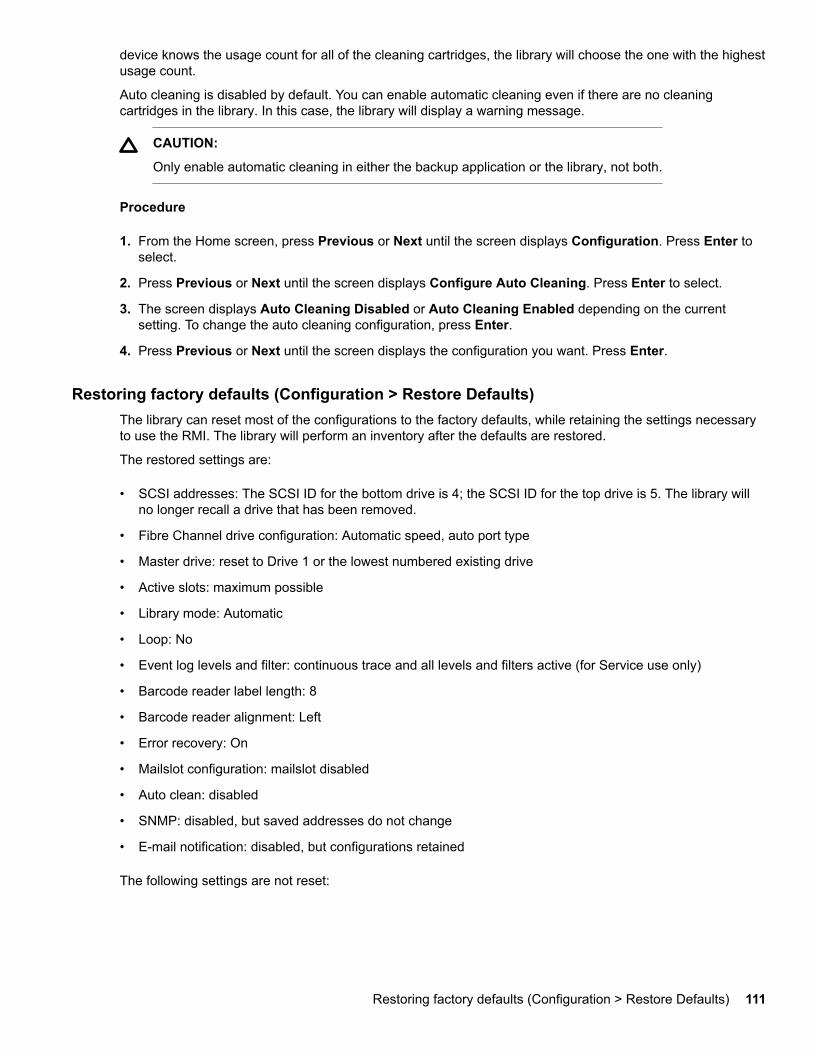
device knows the usage count for all of the cleaning cartridges, the library will choose the one with the highestusage count.
Auto cleaning is disabled by default. You can enable automatic cleaning even if there are no cleaningcartridges in the library. In this case, the library will display a warning message.
CAUTION:
Only enable automatic cleaning in either the backup application or the library, not both.
Procedure
1. From the Home screen, press Previous or Next until the screen displays Configuration. Press Enter toselect.
2. Press Previous or Next until the screen displays Configure Auto Cleaning. Press Enter to select.
3. The screen displays Auto Cleaning Disabled or Auto Cleaning Enabled depending on the currentsetting. To change the auto cleaning configuration, press Enter.
4. Press Previous or Next until the screen displays the configuration you want. Press Enter.
Restoring factory defaults (Configuration > Restore Defaults)The library can reset most of the configurations to the factory defaults, while retaining the settings necessaryto use the RMI. The library will perform an inventory after the defaults are restored.
The restored settings are:
• SCSI addresses: The SCSI ID for the bottom drive is 4; the SCSI ID for the top drive is 5. The library willno longer recall a drive that has been removed.
• Fibre Channel drive configuration: Automatic speed, auto port type
• Master drive: reset to Drive 1 or the lowest numbered existing drive
• Active slots: maximum possible
• Library mode: Automatic
• Loop: No
• Event log levels and filter: continuous trace and all levels and filters active (for Service use only)
• Barcode reader label length: 8
• Barcode reader alignment: Left
• Error recovery: On
• Mailslot configuration: mailslot disabled
• Auto clean: disabled
• SNMP: disabled, but saved addresses do not change
• E-mail notification: disabled, but configurations retained
The following settings are not reset:
Restoring factory defaults (Configuration > Restore Defaults) 111
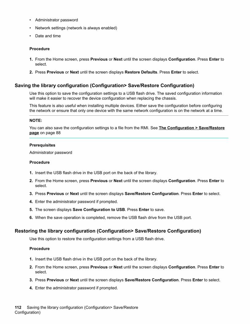
• Administrator password
• Network settings (network is always enabled)
• Date and time
Procedure
1. From the Home screen, press Previous or Next until the screen displays Configuration. Press Enter toselect.
2. Press Previous or Next until the screen displays Restore Defaults. Press Enter to select.
Saving the library configuration (Configuration> Save/Restore Configuration)Use this option to save the configuration settings to a USB flash drive. The saved configuration informationwill make it easier to recover the device configuration when replacing the chassis.
This feature is also useful when installing multiple devices. Either save the configuration before configuringthe network or ensure that only one device with the same network configuration is on the network at a time.
NOTE:
You can also save the configuration settings to a file from the RMI. See The Configuration > Save/Restorepage on page 88
Prerequisites
Administrator password
Procedure
1. Insert the USB flash drive in the USB port on the back of the library.
2. From the Home screen, press Previous or Next until the screen displays Configuration. Press Enter toselect.
3. Press Previous or Next until the screen displays Save/Restore Configuration. Press Enter to select.
4. Enter the administrator password if prompted.
5. The screen displays Save Configuration to USB. Press Enter to save.
6. When the save operation is completed, remove the USB flash drive from the USB port.
Restoring the library configuration (Configuration> Save/Restore Configuration)Use this option to restore the configuration settings from a USB flash drive.
Procedure
1. Insert the USB flash drive in the USB port on the back of the library.
2. From the Home screen, press Previous or Next until the screen displays Configuration. Press Enter toselect.
3. Press Previous or Next until the screen displays Save/Restore Configuration. Press Enter to select.
4. Enter the administrator password if prompted.
112 Saving the library configuration (Configuration> Save/RestoreConfiguration)
5. Press Previous or Next until the screen displays Restore Config from USB. Press Enter.
6. Press Previous or Next until the screen displays the filename of the device configuration file on the USBdrive. Press Enter to select the firmware file.
7. When the restore operation is completed, remove the USB flash drive from the USB port.
Accessing the operations functionsThe Operations menu provides access to the following functions:
• Unlocking, removing, and replacing magazines (Operations > Unlock Left or Right Magazine) onpage 113
• Cleaning a tape drive (Operations > Clean Drive) on page 114
• Moving tapes in the library (Operations > Move Tape) on page 115
• Updating tape cartridge inventory (Operations > Perform Inventory) on page 116
• Rebooting the library (Operations > Reboot Library) on page 116
• Enabling password locks (Operations > Enable Library Password Locks) on page 116
Procedure
1. From the Home screen, press Previous or Next until the screen displays Operations. Press Enter toselect.
2. Press Previous or Next until the screen displays your selected function. Press Enter to select.
Unlocking, removing, and replacing magazines (Operations > Unlock Left or RightMagazine)
Prerequisites
Administrator password
Procedure
1. From the Home screen, press Previous or Next on the OCP until the screen displays Operations.
2. Press Enter to select.
3. Press Previous or Next until the screen displays either Unlock Left Magazine or Unlock RightMagazine.
4. Press Enter to select the desired magazine to unlock.
5. Enter the administrator password if requested.
6. The display reads Left Magazine Unlocked or Right Magazine Unlocked.
7. Pull the released magazine out of the library.
8. The screen now displays Insert Left Magazine or Insert Right Magazine. The library cannot perform anyother operation until the magazine is replaced. After exchanging tapes in a magazine, slide the magazinecompletely into the library. The magazine locks into place once it is correctly installed and the device
Accessing the operations functions 113
inventories the magazine. The Ready LED blinks while the device inventories the magazine and thenstops when the operation is complete.
Cleaning a tape drive (Operations > Clean Drive)When the Clean LED is on, a tape drive is ready for cleaning. Cleaning times can range from a few secondsto a few minutes during which time the Ready LED blinks. Use only the designated cleaning cartridge for yourtape drive model.
Use only Ultrium Universal cleaning cartridges.
IMPORTANT:
If the cleaning cartridge is not a valid cleaning cartridge, the LCD screen displays Invalid Tape and thecartridge is returned to its original location.
IMPORTANT:
If the Clean LED or the Attention LED (on load or unload) lights when inserting the same cartridge afteryou have cleaned the drive, there might be a problem with that cartridge.
If you use the OCP to clean the tape drive, load the cleaning cartridge into the mailslot or any other empty slotbefore beginning the cleaning steps. If you would like to keep a cleaning cartridge in the device, the backupsoftware must manage tape drive cleaning or be configured to bypass the slot containing the cleaningcartridge.
Procedure
1. Make sure that a cleaning cartridge is in the mailslot or one of the magazines.
2. From the Home Screen, press Previous or Next until the screen displays Operations. Press Enter toselect.
3. Press Previous or Next until the screen displays Clean Drive. Press Enter to select.
4. Use Previous or Next until the screen displays Drive 1 or Drive 2. The second line can display eitherClean Required or Good for both drives. Select the drive for Clean Required.
5. When the screen displays the correct drive, press Enter.
The screen displays either Cleaning Tape Slot 4 or Cleaning Tape Slot XX, where XX representsflashing blocks. If a slot number is displayed, the tape in that slot has a bar code label identifying the tapeas a cleaning tape. If a slot number is displayed, continue to Step 6. If no slot number is displayed, itindicates that the device is not able to detect that a cleaning tape with a bar code is in the device. In thiscase, the operator must select the slot where a cleaning tape resides.
6. Use Previous or Next to display the location of a cleaning tape.
7. When the correct location for the cleaning tape is displayed, press Enter to select.
While the library cleans the drive, the screen displays Cleaning Drive 1 in progress or Cleaning Drive 2in progress.
After the cleaning cycle is complete, the screen displays either Cleaning Drive 1 Complete , or CleaningDrive 1 Failed . If the cleaning cycle failed, press Enter to display the error code and message explainingthe failure.
The library returns the cleaning cartridge to the original slot. If you loaded the cartridge from the frontpanel, unload it now by using the mailslot or by removing the magazine. When the tape drive cleaningcycle is complete, the Clean LED turns off (if previously on).
114 Cleaning a tape drive (Operations > Clean Drive)
Moving tapes in the library (Operations > Move Tape)Use this option to move a cartridge from a tape drive, a tape slot in any magazine or the mailslot to any otherlocation not already holding a tape. You can also load and unload tape cartridges to and from the installedtape drives. Select where you want to move the tape from and then indicate where you want to move the tapeto.
Prerequisites
Administrator password.
Procedure
1. From the Home screen, press Previous or Next until the screen displays Operations. Press Enter toselect.
2. Press Previous or Next until the screen displays Move Tape. Press Enter to select.
3. Enter the administrator password if prompted. Use Previous or Next to select the source.
• Mailslot
• Right Magazine
• Left Magazine
• Drive 1
• Drive 2 (if two drives are present)
4. When the correct source is displayed, press Enter to select.
5. If the source selected is a magazine, use Previous or Next to select the slot. Only slots with tapes arelisted. The second line displays the bar code for the tape or reads Full.
6. Once the correct slot is displayed, press Enter to select.
You have now selected the tape you would like to move. The screen now requests the destination for thistape.
7. Use Previous or Next to select from the destination.
• Mailslot
• Right Magazine
• Left Magazine
• Drive 1
• Drive 2 (if two drives are present)
8. When the correct destination is displayed, press Enter to select.
9. If the destination selected is a magazine, use Previous or Next to display the slot. Only empty slots arelisted.
Once the correct slot is displayed, press Enter to select. The library now moves the tape from the selectedsource, to the selected destination. While the library moves the tape, the screen displays Moving Tape.Once the tape has been moved, the screen displays either Move Complete, or Move Failed. If the movefailed, press Enter to display the error code and message explaining the failure.
Moving tapes in the library (Operations > Move Tape) 115
Updating tape cartridge inventory (Operations > Perform Inventory)This option updates the library tape cartridge inventory. The device checks each slot and drive to determinewhich tape, if any, is present.
NOTE:
This command is only needed if the inventory in the library is different than the inventory displayed on thefront panel, which would not happen under normal conditions.
Procedure
1. From the Home screen, press Previous or Next until the screen displays Operations. Press Enter toselect.
2. Press Previous or Next until the screen displays Perform Inventory. Press Enter to select.
3. While the inventory is in progress, the screen displays Inventory in Progress...
4. The library now checks the drive and each slot for the presence of a tape to update the inventoryinformation. The Ready LED blinks during this operation.
Rebooting the library (Operations > Reboot Library)This option reboots the library and forces a new cartridge inventory, clearing any current error condition.
CAUTION:
This option interrupts the current backup or restore operation and causes the operation to fail. Use thisoption if the device is in an error state.
Procedure
1. From the Home screen, press Previous or Next until the screen displays Operations. Press Enter toselect.
2. Press Previous or Next until the screen displays Reboot Library. Press Enter to select.
3. The Ready LED blinks during the reboot operation.
Enabling password locks (Operations > Enable Library Password Locks)This option locks the restricted areas. This option is typically used if you do not want to wait for the time out toreset the locks. Power cycling or rebooting the library also resets the locks.
Procedure
1. From the Home screen, press Previous or Next until the screen displays Operations. Press Enter toselect.
2. Press Previous or Next until the screen displays Enable Library Password Locks. Press Enter toselect.
Accessing the support functionsThe Support menu provides access to the following support functions:
116 Updating tape cartridge inventory (Operations > Perform Inventory)

• Powering a drive on or off (Support > Power On/Off Drive) on page 117
• Running the demonstration (Support > Run Demo) on page 117
• Running the slot to slot test (Support > Run Slot To Slot Test) on page 118
• Running the wellness test (Support > Run Wellness Test) on page 118
• Upgrading firmware (Support > Library FW Upgrade) on page 119
• Downloading a support ticket (Support > Download Support Ticket) on page 121
• Viewing logs (Support > Library Error Log) on page 121
• Forcing the drive to eject a tape (Support > Force Drive To Eject Tape) on page 122
Procedure
1. From the Home screen, press Previous or Next until the screen displays Support. Press Enter to select.
2. Press Previous or Next until the screen displays your selected function. Press Enter to select.
Powering a drive on or off (Support > Power On/Off Drive)Use this option to power a drive on or off without interrupting power to the rest of the library and the seconddrive. This option is typically used when replacing one drive in a two-drive configuration.
Prerequisites
Administrator password.
Procedure
1. From the Home screen, press Previous or Next until the screen displays Support. Press Enter to select.
2. Press Previous or Next until the screen displays Power On/Off Drives. Press Enter to select.
3. Enter the administrator password, if prompted.
4. Press Previous or Next until the screen displays the drive you are powering on or off. The screen displaysDrive 1. The second line in the screen displays the current state, which is either Power ON or PowerOFF.
5. To change the power status, press Enter. The screen displays either Press Enter to Power off DRV 1, orPress Enter to Power on DRV 1. Press Enter to select. The Ready LED blinks during the operations.
Running the demonstration (Support > Run Demo)Use this option to run a device demonstration program. The demonstration continues until the OCP Cancelbutton is pressed. During the demonstration, the device will move cartridges to the tape drive and back. At theend of the demonstration, the cartridges are returned to their original slots.
NOTE:
To stop the demonstration, press Cancel on the OCP.
Prerequisites
Administrator password.
Powering a drive on or off (Support > Power On/Off Drive) 117
Procedure
1. From the Home screen, press Previous or Next until the screen displays Support. Press Enter to select.
2. Press Previous or Next until the screen displays Run Demo. Press Enter to select.
3. Enter the administrator password if prompted.
4. Use Previous and Next to select the number of cycles: 270, 540, 1080, or Endless. Press Enter to startthe demonstration.
5. While the test is running, the first line of the screen displays Demo Test. The second line displays thenumber of cycles completed and the number of errors. The Ready LED blinks until the test is complete.
Running the slot to slot test (Support > Run Slot To Slot Test)Use this option to verify that the robot can move media in and out of each of the magazine slots.
To stop the slot to slot test, press the Cancel button.
NOTE:
At the end of the test, the cartridges are NOT returned to their original slots.
Prerequisites
Administrator password
Procedure
1. From the Home screen, press Previous or Next until the screen displays Support. Press Enter to select.
2. Press Previous or Next until the screen displays Run Slot To Slot Test. Press Enter to select.
3. Enter the administrator password, if prompted.
4. Press Previous or Next until the screen displays Select Number of Cycles. Use Previous or Next toselect the number of cycles: 270, 540, 1080, or Endless. Press Enter.
5. While the test is running, the screen displays progress as shown: Run Slot To Slot. The second line onthe display shows the number of cycles completed. The Ready LED blinks until the test is complete.
6. When the test is complete, the screen displays the number of cycles completed and the number of errors.If the test failed, press Enter to display the error and message describing the cause.
Running the wellness test (Support > Run Wellness Test)Use this option to check the health of the library for the specified number of loops. If a failure occurs duringthe test, check the error code and failure message for more information. Access to this feature requires theadministrator password. For more information about the wellness test, see The wellness test on page 163.
For complete testing, enable the mailslot and ensure that each top-row corner slot contains a tape cartridge.During the test, the library will open the mailslot and ask you to insert a tape cartridge. You can use anycompatible Ultrium data tape cartridge for this test.
IMPORTANT:
The library will remove any tape cartridges from tape drives and go offline when running the wellnesstest. Verify that any applications using the library have completed before starting the wellness test.
To stop the wellness test, press the Cancel button.
118 Running the slot to slot test (Support > Run Slot To Slot Test)
Prerequisites
Administrator password.
Procedure
1. From the Home screen, press Previous or Next until the screen displays Support. Press Enter to select.
2. Press Previous or Next until the screen displays Run Wellness Test. Press Enter to select.
3. Enter the administrator password, if prompted.
4. On a library with two tape drives, press Previous or Next to select the tape drive to test: Drive 1, Drive 2,or All Drives. Press Enter to select the drive option.
5. Use Previous or Next to select a number of cycles: 1 - 10. Press Enter.
6. While the test is running, the screen displays progress as shown: Wellness test. The second line on thedisplay shows the number of cycles completed. The Ready LED blinks until the test is complete.
7. When the test is complete, the screen displays the test completion status, including any recoveries orerrors that might have occurred. See Error codes on page 166 for a list of error codes and errormessages.
Upgrading firmware (Support > Library FW Upgrade)The library allows two types of firmware to be upgraded — one for the tape drive and the other for the libraryitself. You can upgrade both types of firmware from a USB flash drive. You can also upgrade the tape drivefirmware from a firmware upgrade tape. Access to this feature requires the administrator password.
The library only supports signed firmware image upgrades and downgrades. Once firmware that uses codesigning is loaded, the firmware will reject all unsigned images. If you attempt to load an unsigned firmwareimage, the RMI displays an invalid firmware version error message.
If you see this message, download the latest signed firmware image from the support website at http://www.hpe.com/support/storage.
Prerequisites
Administrator password.
Procedure
1. Download current library firmware using Library & Tape Tools or from the Hewlett Packard Enterprisesupport website at http://www.hpe.com/support/storage. Copy the firmware onto the USB flash drive.
TIP:
The display will only show the first 16 characters of the file name. If the USB drive has multiplefirmware files, ensure that you can distinguish the files from the first 16 characters in their file names.
2. Insert the USB flash drive into the USB port on the back of the library.
3. From the Home screen, press Previous or Next until the screen displays Support. Press Enter to select.
4. Press Previous or Next until the screen displays Library FW upgrade. Press Enter to select.
5. Enter the administrator password if prompted.
6. Press Previous or Next until the screen displays the filename of the library\ firmware file on the USB drive.Press Enter to select the firmware file.
Upgrading firmware (Support > Library FW Upgrade) 119
7. If the upgrade failed, press Enter to display the error code and message describing the cause of thefailure.
8. Remove the USB flash drive from the USB port.
Upgrading drive firmware from a USB flash drive (Support> Drive FW Upgrade)The library allows two types of firmware to be upgraded — one for the tape drive and the other for the libraryitself. You can upgrade both types of firmware from a USB flash drive. You can also upgrade the tape drivefirmware from a firmware upgrade tape.
The library only supports signed firmware image upgrades and downgrades. Once firmware that uses codesigning is loaded, the firmware will reject all unsigned images. If you attempt to load an unsigned firmwareimage, the RMI displays an invalid firmware version error message.
If you see this message, download the latest signed firmware image from the MSL website at http://www.hpe.com/info/msl.
Prerequisites
Administrator password.
Procedure
1. Insert the USB flash drive into the USB port on the back of the device.
2. From the Home screen, press Previous or Next until the screen displays Support. Press Enter to select.
3. Press Previous or Next until the screen displays Drive FW Upgrade. Press Enter to select.
4. Enter the administrator password if prompted.
5. Press Previous or Next until the screen displays Drive FW Upgrade by USB. Press Enter to select.
6. Press Previous or Next until the screen displays the filename of the drive firmware file on the USB drive.Press Enter to select the firmware file.
If the upgrade failed, press Enter to display the error code and message describing the cause of thefailure.
7. Remove the USB flash drive from the USB port.
Upgrading drive firmware from a firmware upgrade tape (Support> Drive FW Upgrade)The library allows two types of firmware to be upgraded — one for the tape drive and the other for the libraryitself. You can upgrade both types of firmware from a USB flash drive. You can also upgrade the tape drivefirmware from a firmware upgrade tape. Access to this feature requires the administrator password.
The library only supports signed firmware image upgrades and downgrades. Once firmware that uses codesigning is loaded, the firmware will reject all unsigned images. If you attempt to load an unsigned firmwareimage, the RMI displays an invalid firmware version error message.
If you see this message, download the latest signed firmware image from the MSL website at http://www.hpe.com/info/msl.
Prerequisites
Administrator password
120 Upgrading drive firmware from a USB flash drive (Support> Drive FWUpgrade)
Procedure
1. Load a firmware upgrade tape into the mailslot or any open slot. If all slots are full, remove a data tape tomake room for the firmware upgrade tape.
2. From the Home screen, press Previous or Next until the screen displays Support. Press Enter to select.
3. Enter the administrator password if prompted.
4. Press Previous or Next until the screen displays Drive FW Upgrade. Press Enter to select.
5. Press Previous or Next until the screen displays Drive FW Upgrade by Tape. Press Enter to select.
6. Press Previous or Next until the display shows the correct slot location of the firmware upgrade tapeinstalled in the device (example) FW Tape Location Slot: Mailslot. Press Enter to select the correctfirmware tape location. The screen displays Upgrading Drive FW.
When the update is complete, the screen displays either Success Export FW Tape, or Failed Export FWTape.
7. If the upgrade failed, press Enter to display the error code and message describing the cause of thefailure.
8. Remove the firmware upgrade tape from the library using either the mailslot or by removing the magazinewhere the tape has been placed.
Viewing logs (Support > Library Error Log)The library keeps a log of recent error and warning messages. See Error codes on page 166 for moreinformation about error codes.
Procedure
1. From the Home screen, press Previous or Next until the screen displays Support. Press Enter to select.
2. Press Previous or Next until the screen displays Library Error Log to see error messages or LibraryWarning Log to see warnings. Press Enter to select.
3. Enter the administrator password, if prompted.
4. Press Enter to see the message description. Press Cancel to return to the message code.
5. Press Next to see the next message.
Downloading a support ticket (Support > Download Support Ticket)A support ticket contains information that can help a system administrator or support engineer diagnoselibrary problems. Use this option to download a support ticket to a USB flash drive. Downloading the supportticket to a USB flash drive lets you view the ticket on a computer that is not connected to the library.
You can view the support ticket with the Library & Tape Tools.
Procedure
1. Insert a USB flash drive into the USB port on the back panel.
2. From the Home screen, press Previous or Next until the screen displays Support. Press Enter to select.
3. Press Previous or Next until the screen displays Download Support Ticket. Press Enter to select.
Viewing logs (Support > Library Error Log) 121
Forcing the drive to eject a tape (Support > Force Drive To Eject Tape)Use this option to make the tape drive eject the tape and place it into an open slot. Before issuing thiscommand, attempt to eject the tape with the move command (See Moving tapes in the library (Operations> Move Tape) on page 115).
Procedure
1. From the Home screen, press Previous or Next until the screen displays Support. Press Enter to select.
2. Press Previous or Next until the screen displays Force Drive To Eject Tape. Press Enter to select.
3. Press Previous or Next until the screen displays Drive 1 or Drive 2. The second line on the display showsthe bar code number of the tape, Full, or Empty. To select the desired drive to eject the tape, press Enter.
4. If the tape is successfully ejected from the drive, the screen displays the slot location where the tape wasmoved to.
NOTE:
If the drive has difficulty ejecting the tape, suspect bad or damaged media.
Using the MSL4048, MSL8048, and MSL8096 OCP
OverviewThe front panel includes:
• A liquid crystal display (LCD) that shows tape library status information and is used to access the OCPmenus.
• LEDs that illuminate to indicate library conditions and alerts.
• Navigation buttons that allow you to scroll through, select, and make changes to different OCP menus andsettings.
This panel provides everything you need to monitor library status and access the OCP menus.
Operations available using the OCP
• Info menu on page 133
◦ Viewing status information (Info > Status) on page 133
◦ Viewing identity information (Info > Identity Library) on page 133
◦ Viewing identity information (Info > Identity Drives) on page 134
◦ Viewing inventory information (Info > Inventory) on page 134
◦ Viewing network information (Info > Network) on page 134
• Configuration menu on page 134
◦ Changing the number of logical libraries (Configuration > Logical Libraries) on page 135
◦ Changing the library configuration (Configuration > Library) on page 135
122 Forcing the drive to eject a tape (Support > Force Drive To Eject Tape)
◦ Changing the drive configuration (Configuration > Drives) on page 137
◦ Changing the network configuration (Configuration > Network) on page 137
◦ Barcode reporting format (Configuration > Barcode Reporting) on page 137
◦ Setting and changing the administrator password (Configuration> Set Admin Password) on page137
◦ Restore defaults (Configuration > Restore Defaults) on page 138
◦ Setting the library date and time (Configuration > Set Date and Time) on page 139
◦ Display Contrast
◦ Saving and restoring the library configuration (Configuration> Save/Restore) on page 139
• Operations menu on page 139
◦ Opening the mailslot (Operations > Open Mailslot) on page 140
◦ Unlocking, removing, and replacing magazines (Operations > Unlock Left/Right Magazines) onpage 131
◦ Moving Media (Operations > Move Media) on page 141
◦ Performing Inventory (Operations > Inventory) on page 141
◦ Enabling Password Locks (Operations > Enable Password Locks) on page 141
• Support menu on page 141
◦ Powering drives on and off (Support > Power on/off Drives) on page 141
◦ Cleaning the tape drive (Support > Clean Drive) on page 141
◦ Running tests (Support > Run Tests) on page 142
◦ Viewing logs (Support > View Logs) on page 142
◦ Updating library and drive firmware (Support > FW Upgrade) on page 142
◦ Force ejecting a drive (Support > Force Drive Eject) on page 144
◦ Rebooting the tape library (Support > Reboot) on page 144
OCP navigation buttonsFour menus are accessed through the OCP: Info, Configuration, Operations, and Support. Use thenavigation buttons to select menu items and work with the screen displays. The navigation buttons havedifferent functions depending upon where you are in the menu structure.
OCP navigation buttons 123
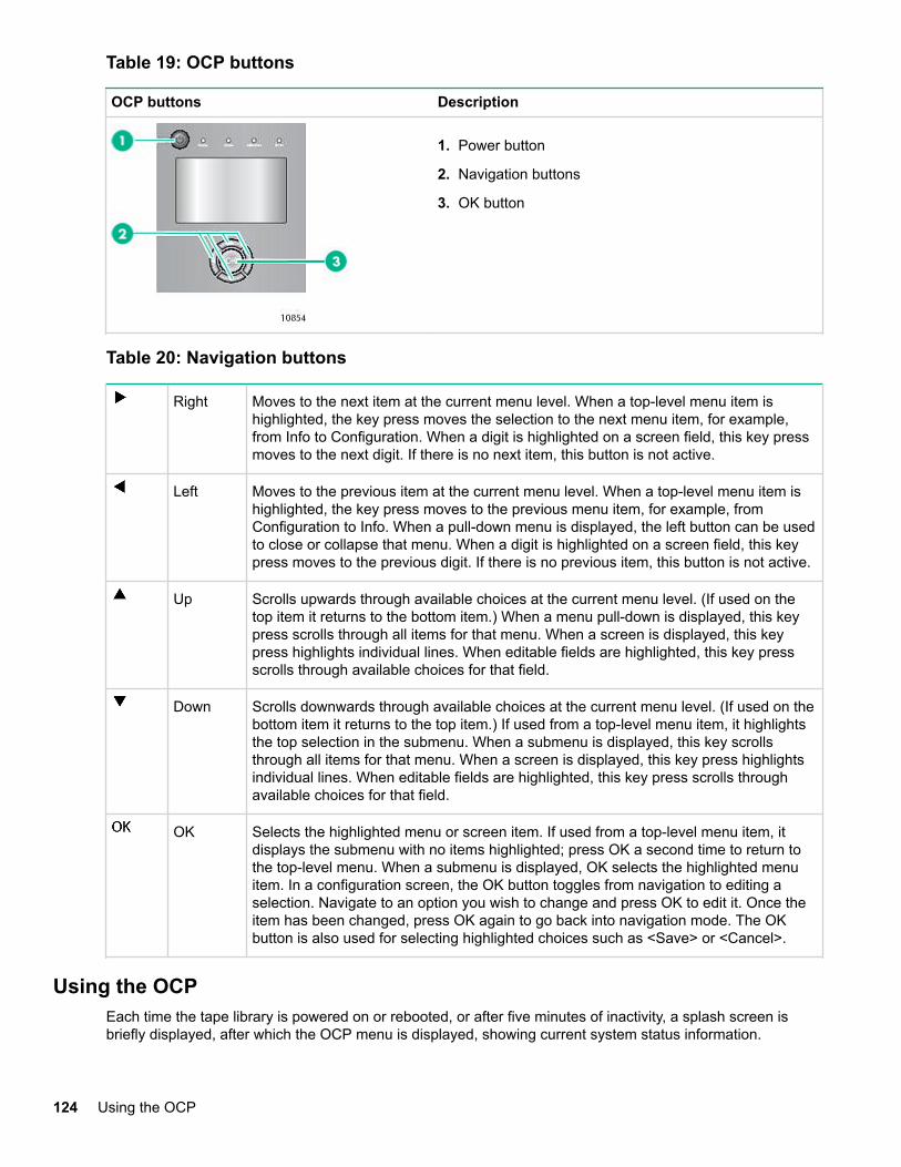
Table 19: OCP buttons
OCP buttons Description
1. Power button
2. Navigation buttons
3. OK button
Table 20: Navigation buttons
Right Moves to the next item at the current menu level. When a top-level menu item ishighlighted, the key press moves the selection to the next menu item, for example,from Info to Configuration. When a digit is highlighted on a screen field, this key pressmoves to the next digit. If there is no next item, this button is not active.
Left Moves to the previous item at the current menu level. When a top-level menu item ishighlighted, the key press moves to the previous menu item, for example, fromConfiguration to Info. When a pull-down menu is displayed, the left button can be usedto close or collapse that menu. When a digit is highlighted on a screen field, this keypress moves to the previous digit. If there is no previous item, this button is not active.
Up Scrolls upwards through available choices at the current menu level. (If used on thetop item it returns to the bottom item.) When a menu pull-down is displayed, this keypress scrolls through all items for that menu. When a screen is displayed, this keypress highlights individual lines. When editable fields are highlighted, this key pressscrolls through available choices for that field.
Down Scrolls downwards through available choices at the current menu level. (If used on thebottom item it returns to the top item.) If used from a top-level menu item, it highlightsthe top selection in the submenu. When a submenu is displayed, this key scrollsthrough all items for that menu. When a screen is displayed, this key press highlightsindividual lines. When editable fields are highlighted, this key press scrolls throughavailable choices for that field.
OK Selects the highlighted menu or screen item. If used from a top-level menu item, itdisplays the submenu with no items highlighted; press OK a second time to return tothe top-level menu. When a submenu is displayed, OK selects the highlighted menuitem. In a configuration screen, the OK button toggles from navigation to editing aselection. Navigate to an option you wish to change and press OK to edit it. Once theitem has been changed, press OK again to go back into navigation mode. The OKbutton is also used for selecting highlighted choices such as <Save> or <Cancel>.
Using the OCPEach time the tape library is powered on or rebooted, or after five minutes of inactivity, a splash screen isbriefly displayed, after which the OCP menu is displayed, showing current system status information.
124 Using the OCP
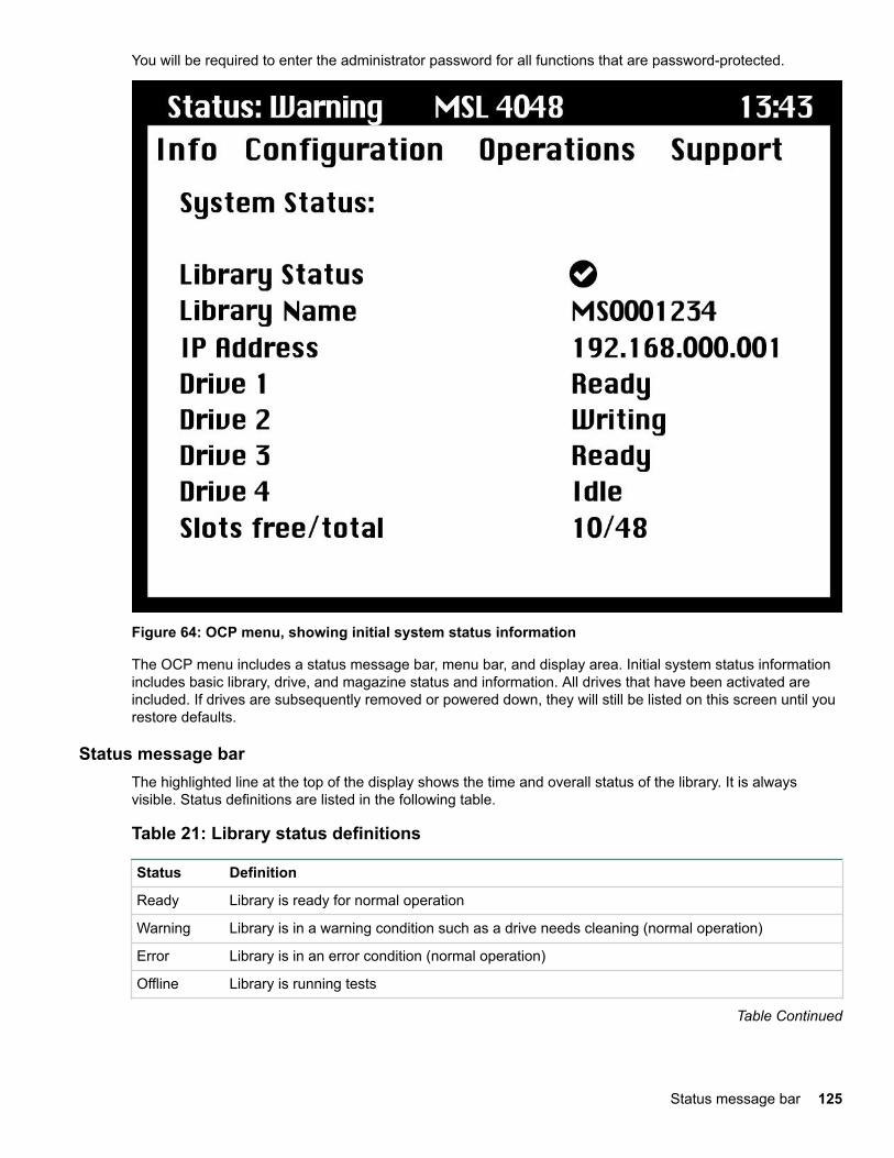
You will be required to enter the administrator password for all functions that are password-protected.
Figure 64: OCP menu, showing initial system status information
The OCP menu includes a status message bar, menu bar, and display area. Initial system status informationincludes basic library, drive, and magazine status and information. All drives that have been activated areincluded. If drives are subsequently removed or powered down, they will still be listed on this screen until yourestore defaults.
Status message barThe highlighted line at the top of the display shows the time and overall status of the library. It is alwaysvisible. Status definitions are listed in the following table.
Table 21: Library status definitions
Status Definition
Ready Library is ready for normal operation
Warning Library is in a warning condition such as a drive needs cleaning (normal operation)
Error Library is in an error condition (normal operation)
Offline Library is running tests
Table Continued
Status message bar 125

Status Definition
Load Library is loading a tape
Unload Library is unloading a tape
Menu barThe menu bar contains four groups of menu functions:
• Info
• Configuration
• Operations
• Support
126 Menu bar
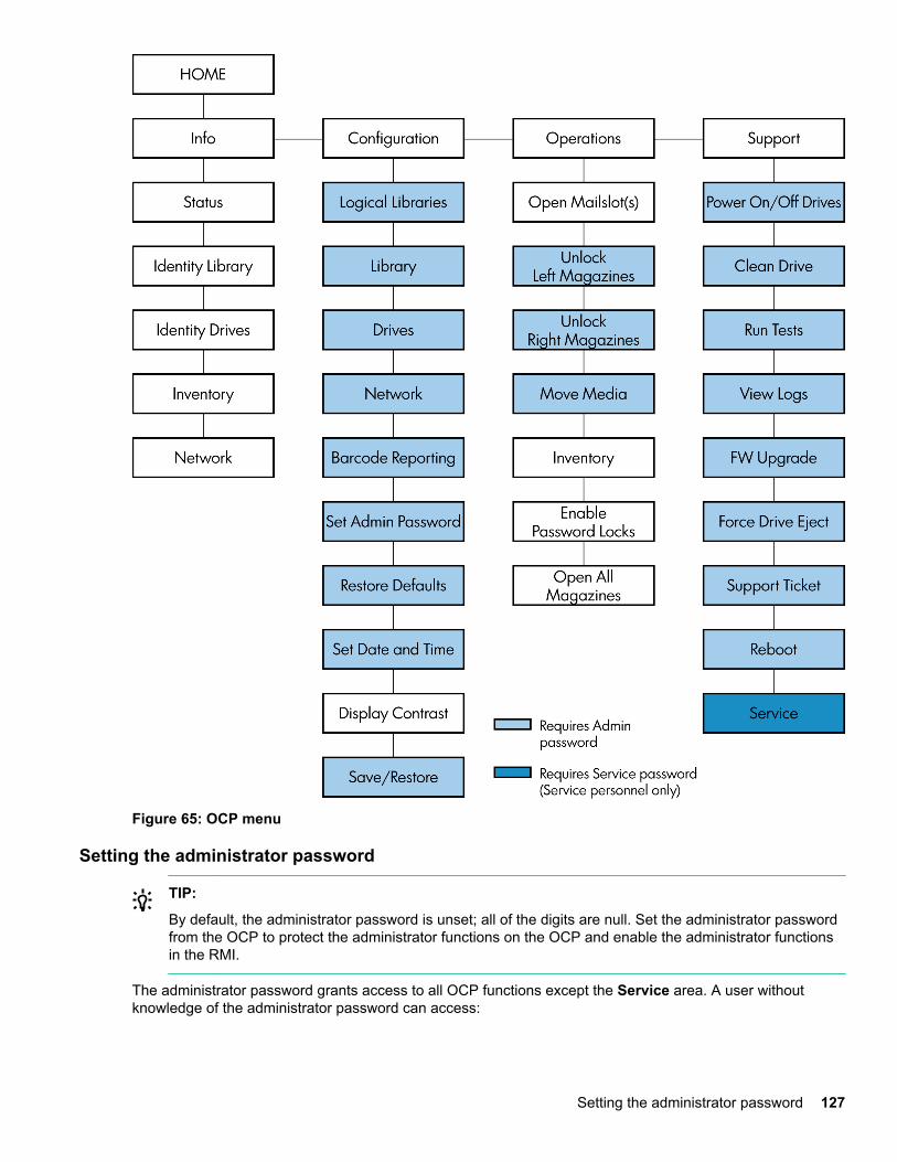
Figure 65: OCP menu
Setting the administrator password
TIP:
By default, the administrator password is unset; all of the digits are null. Set the administrator passwordfrom the OCP to protect the administrator functions on the OCP and enable the administrator functionsin the RMI.
The administrator password grants access to all OCP functions except the Service area. A user withoutknowledge of the administrator password can access:
Setting the administrator password 127
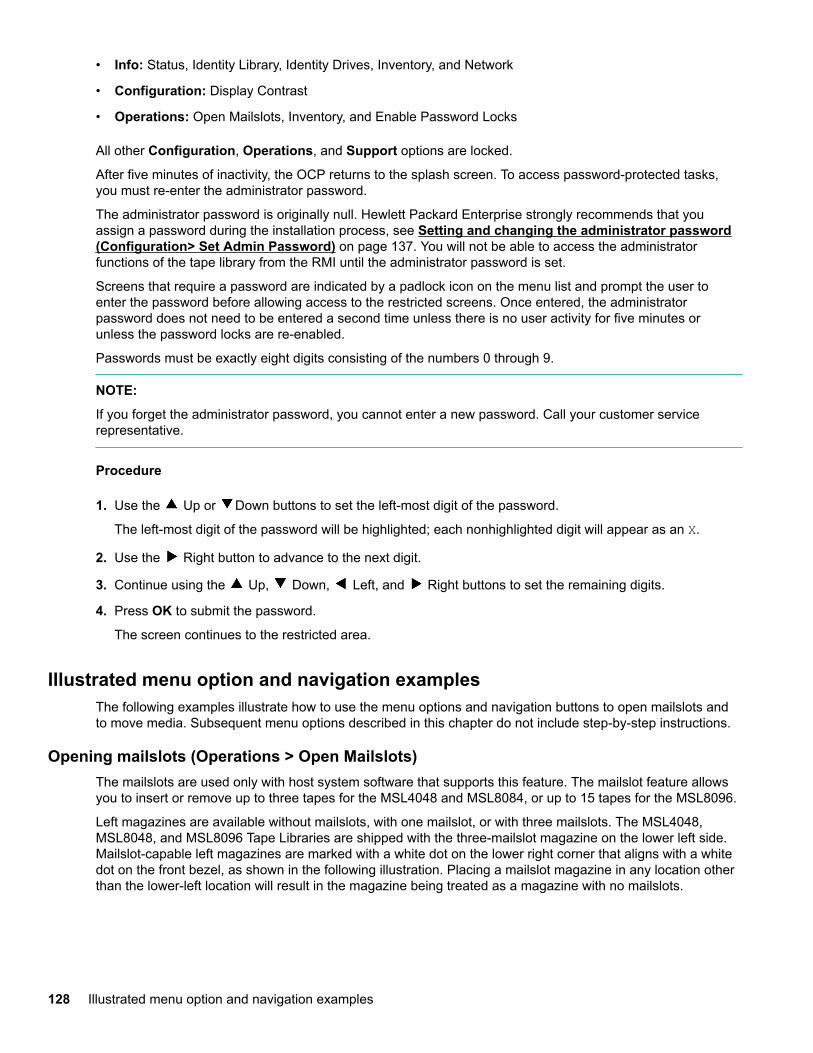
• Info: Status, Identity Library, Identity Drives, Inventory, and Network
• Configuration: Display Contrast
• Operations: Open Mailslots, Inventory, and Enable Password Locks
All other Configuration, Operations, and Support options are locked.
After five minutes of inactivity, the OCP returns to the splash screen. To access password-protected tasks,you must re-enter the administrator password.
The administrator password is originally null. Hewlett Packard Enterprise strongly recommends that youassign a password during the installation process, see Setting and changing the administrator password(Configuration> Set Admin Password) on page 137. You will not be able to access the administratorfunctions of the tape library from the RMI until the administrator password is set.
Screens that require a password are indicated by a padlock icon on the menu list and prompt the user toenter the password before allowing access to the restricted screens. Once entered, the administratorpassword does not need to be entered a second time unless there is no user activity for five minutes orunless the password locks are re-enabled.
Passwords must be exactly eight digits consisting of the numbers 0 through 9.
NOTE:
If you forget the administrator password, you cannot enter a new password. Call your customer servicerepresentative.
Procedure
1. Use the Up or Down buttons to set the left-most digit of the password.
The left-most digit of the password will be highlighted; each nonhighlighted digit will appear as an X.
2. Use the Right button to advance to the next digit.
3. Continue using the Up, Down, Left, and Right buttons to set the remaining digits.
4. Press OK to submit the password.
The screen continues to the restricted area.
Illustrated menu option and navigation examplesThe following examples illustrate how to use the menu options and navigation buttons to open mailslots andto move media. Subsequent menu options described in this chapter do not include step-by-step instructions.
Opening mailslots (Operations > Open Mailslots)The mailslots are used only with host system software that supports this feature. The mailslot feature allowsyou to insert or remove up to three tapes for the MSL4048 and MSL8084, or up to 15 tapes for the MSL8096.
Left magazines are available without mailslots, with one mailslot, or with three mailslots. The MSL4048,MSL8048, and MSL8096 Tape Libraries are shipped with the three-mailslot magazine on the lower left side.Mailslot-capable left magazines are marked with a white dot on the lower right corner that aligns with a whitedot on the front bezel, as shown in the following illustration. Placing a mailslot magazine in any location otherthan the lower-left location will result in the magazine being treated as a magazine with no mailslots.
128 Illustrated menu option and navigation examples
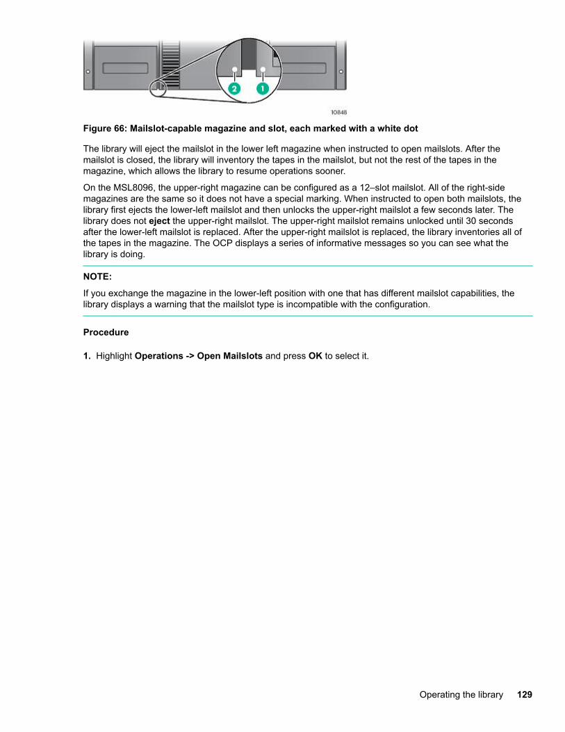
Figure 66: Mailslot-capable magazine and slot, each marked with a white dot
The library will eject the mailslot in the lower left magazine when instructed to open mailslots. After themailslot is closed, the library will inventory the tapes in the mailslot, but not the rest of the tapes in themagazine, which allows the library to resume operations sooner.
On the MSL8096, the upper-right magazine can be configured as a 12–slot mailslot. All of the right-sidemagazines are the same so it does not have a special marking. When instructed to open both mailslots, thelibrary first ejects the lower-left mailslot and then unlocks the upper-right mailslot a few seconds later. Thelibrary does not eject the upper-right mailslot. The upper-right mailslot remains unlocked until 30 secondsafter the lower-left mailslot is replaced. After the upper-right mailslot is replaced, the library inventories all ofthe tapes in the magazine. The OCP displays a series of informative messages so you can see what thelibrary is doing.
NOTE:
If you exchange the magazine in the lower-left position with one that has different mailslot capabilities, thelibrary displays a warning that the mailslot type is incompatible with the configuration.
Procedure
1. Highlight Operations -> Open Mailslots and press OK to select it.
Operating the library 129
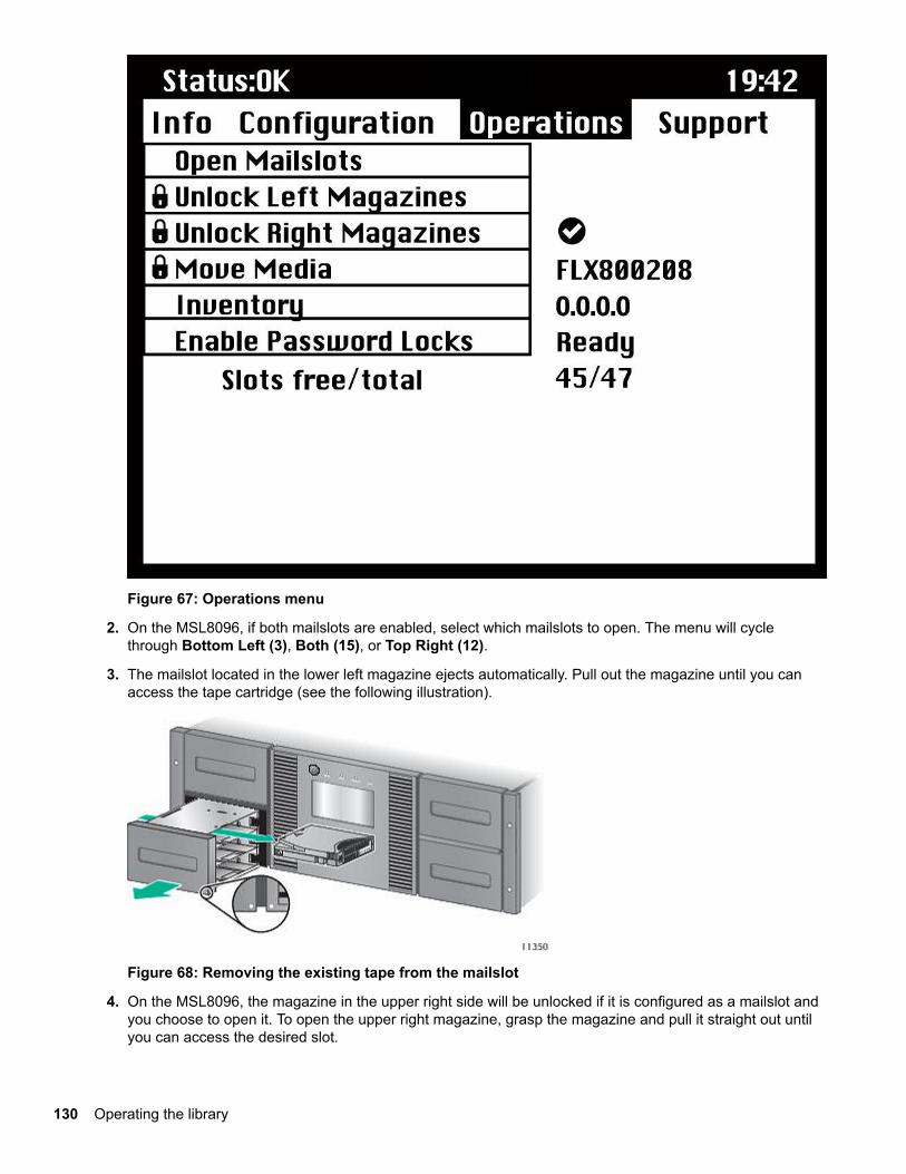
Figure 67: Operations menu
2. On the MSL8096, if both mailslots are enabled, select which mailslots to open. The menu will cyclethrough Bottom Left (3), Both (15), or Top Right (12).
3. The mailslot located in the lower left magazine ejects automatically. Pull out the magazine until you canaccess the tape cartridge (see the following illustration).
Figure 68: Removing the existing tape from the mailslot
4. On the MSL8096, the magazine in the upper right side will be unlocked if it is configured as a mailslot andyou choose to open it. To open the upper right magazine, grasp the magazine and pull it straight out untilyou can access the desired slot.
130 Operating the library
NOTE:
The following message might be displayed:
Mailslot opening. No button pushes are accepted during this time.
NOTE:
If the SCSI Prevent/Allow Media Removal bit is set, the mailslot cannot be unlocked/opened from the frontpanel and the following message is displayed: Media Removal Prevented by Host Software. Press OKto continue and return to the open mailslot pull-down menu. Try the operation again from the backupsoftware.
5. The following message is displayed: Please close Mailslot(s). Remove the existing tape cartridges fromthe mailslot and insert new tape cartridges, as required.
6. Push the mailslot back into the library.
Unlocking, removing, and replacing magazines (Operations > Unlock Left/Right Magazines)This option grants access to the left and right magazines. After exchanging tapes in a magazine, slide themagazine completely into the library. The magazine locks into place. Access to the magazines requires theuse of the administrator password.
On the MSL4048, once all left or right magazines are correctly installed, the library inventories the magazines.The Ready LED blinks during the inventory operation.
On the MSL8048 and MSL8096, the library leaves all magazines on a side unlocked for several seconds.During that time, you can pull out as many magazines on the side as you want. A magazine is locked when itis pushed back into the library. The library will wait about 30 seconds after the last magazine is installedbefore starting the inventory. Before the inventory starts, you can unlock the magazines on either side.
NOTE:
Due to the library design, all left or all right magazines will be unlocked. The library will halt robotic functionsuntil all magazines are present. It is not possible to unlock all of the magazines at once from the front panel.
Moving Media (Operations > Move Media)This option instructs the library to move a cartridge from a tape drive, a tape slot in any magazine or themailslot in the left magazine to any other location not already holding a tape. This option also lets you loadand unload tape cartridges to and from the installed tape drives. To use this command, you must first selectwhere you want to move the tape from (in one of the Source fields), and then indicate where you want tomove the tape to (in one of the Destinations fields).
Source Type: This option toggles between all available sources: mailslot, magazines, and the active drives.
Source -> Source by Label: If appropriate, this option toggles between available source cartridges. In thefollowing example, the source type is a magazine, so you must select a cartridge from the magazine. You cando this by selecting a specific slot (Source field) or specifying the target cartridge barcode (Source by Labelfield). Only Full source slots are available for selection.
Destination Type: This toggles between all available destinations: Mailslot, Magazine, and Drive.
Destination: If appropriate, this option allows you to specify the cartridge destination. For a magazine, selecta slot. Only Empty destination slots are available for selection.
Access to the Move Media option requires the use of the administrator password.
Unlocking, removing, and replacing magazines (Operations > Unlock Left/Right Magazines) 131
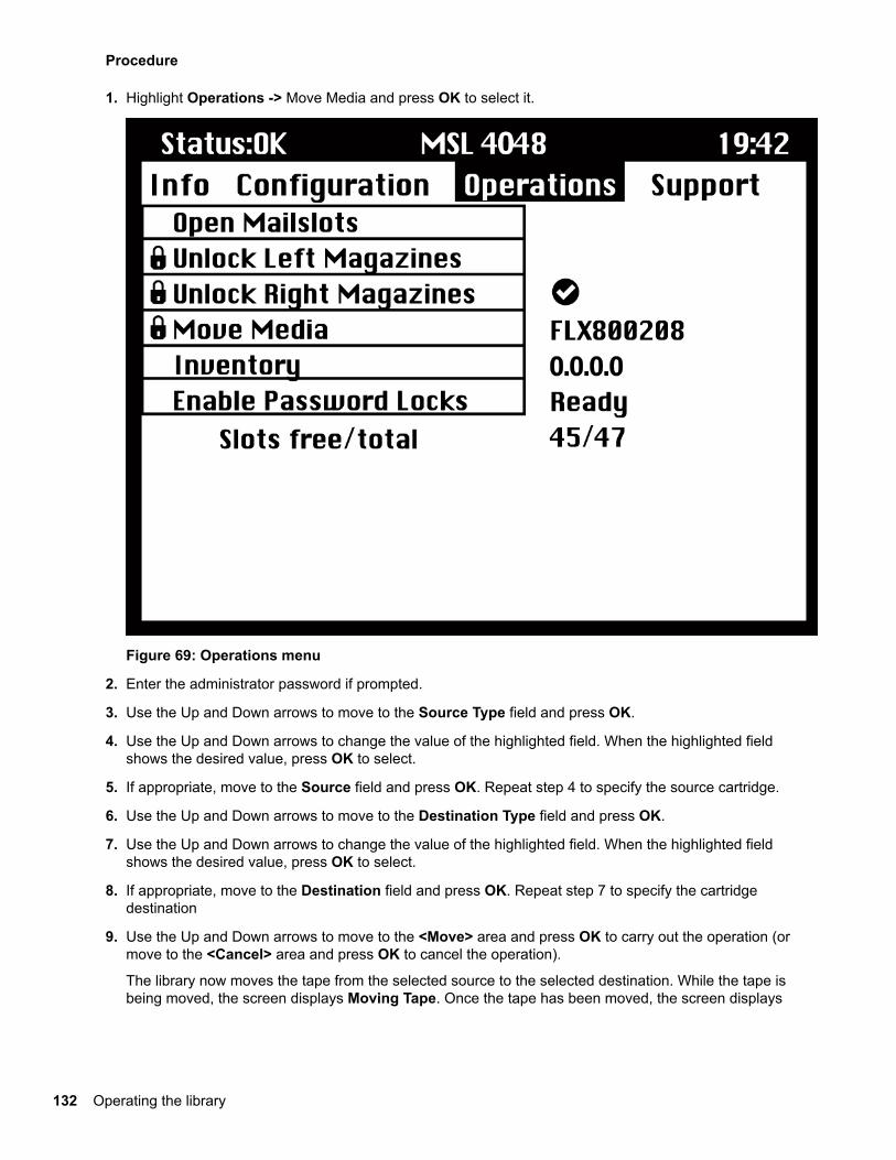
Procedure
1. Highlight Operations -> Move Media and press OK to select it.
Figure 69: Operations menu
2. Enter the administrator password if prompted.
3. Use the Up and Down arrows to move to the Source Type field and press OK.
4. Use the Up and Down arrows to change the value of the highlighted field. When the highlighted fieldshows the desired value, press OK to select.
5. If appropriate, move to the Source field and press OK. Repeat step 4 to specify the source cartridge.
6. Use the Up and Down arrows to move to the Destination Type field and press OK.
7. Use the Up and Down arrows to change the value of the highlighted field. When the highlighted fieldshows the desired value, press OK to select.
8. If appropriate, move to the Destination field and press OK. Repeat step 7 to specify the cartridgedestination
9. Use the Up and Down arrows to move to the <Move> area and press OK to carry out the operation (ormove to the <Cancel> area and press OK to cancel the operation).
The library now moves the tape from the selected source to the selected destination. While the tape isbeing moved, the screen displays Moving Tape. Once the tape has been moved, the screen displays
132 Operating the library
either Move Complete, or Move Failed. If the move failed, press OK to display the error code andmessage explaining the failure.
Info menuThe Info menu options provide the following options. None of these options is password protected.
• Viewing status information (Info > Status) on page 133
• Viewing identity information (Info > Identity Library) on page 133
• Viewing identity information (Info > Identity Drives) on page 134
• Viewing inventory information (Info > Inventory) on page 134
• Viewing network information (Info > Network) on page 134
Viewing status information (Info > Status)Status information can be displayed for the system, the library, or for a specific drive.
NOTE:
The number of drives available for selection in the Status menu depends on the number of drives that havebeen active in the library. For a library that has only two drives, the menu displays Drive 1 and Drive 2. For alibrary that has four drives, the menu displays Drive 1, Drive 2, Drive 3, and Drive 4 (even though the status ofsome might be offline or missing).
• Library: displays the status of the library without the drives. It shows the library status, odometer, poweron time, robotic status, slot and barcode of any cartridge in transport, number of free and total slots, andstatus of the mailslots.
• Drives: displays the status of the selected drive. It shows the drive status, source slot, tape barcode, errorcode (if appropriate), drive temperature, status of cooling fan, and drive activity. For Fibre Channel drives,the following additional items are displayed:
◦ The link status of each port might be: No Light, Logged In, Logged Out, ALPA Conflict, or NegotiationLink. No Light or ALPA Conflict indicates an error condition. See Fibre Channel connection problemson page 145.
◦ The speed for each port: 1 Gb/s, 2 Gb/s, 4 Gb/s, or 8 Gb/s. Only speeds supported by each port aredisplayed.
NOTE:
Use the Left or Right buttons to toggle through the status information for all drives without returning to theInfo -> Status submenu.
Viewing identity information (Info > Identity Library)Displays
• Library serial number
• Library product ID
• Controller and bootcode firmware revisions
Info menu 133

• Library mode
• Number of reserved slots
• Status of the mailslot
• Library LUN Host Drive
A Fibre Channel library also displays the WW Node Name for the FC node to which it is connected.
World Wide names are assigned automatically; they cannot be configured.
Viewing identity information (Info > Identity Drives)Displays the status of the selected drive. It shows the SCSI ID, physical drive number, serial number, firmwarerevision, element address, the ID string, and whether the drive is the library LUN host drive.
The following additional information is displayed for a Fibre Channel drive:
• WWide Node Name for the FC node to which the tape drive is connected.
• WWide Port Name and Port Type for Port A.
• WWide Port Name and Port Type for Port B.
NOTE:
Use the Left or Right buttons to toggle through the identity information for all drives without returning to theInfo -> Identity menu.
World Wide names are assigned automatically; they cannot be configured.
Viewing inventory information (Info > Inventory)Inventory information can be displayed for a magazine or for a drive.
• Magazine: The first inventory screen displays the contents of magazine number 1 (lower left). The topsection of this screen shows which mailslots are occupied (shaded background) or empty (whitebackground). If the mailslot is enabled, the storage slot count is reduced. The lower section gives moreinformation about each slot. Mailslots are identified in the Slot column as MS1, MS2, or MS3. The labelshows any barcode details. Slots containing tapes without barcodes are labeled Full. Info shows whetherthe tape is write-protected (WP) or if that media needs attention (!). Use the Left or Right buttons to scrollthrough and view the inventory for all magazines.
• Drive: This screen displays the contents of each drive. The Label column identifies which tape is in thedrive and the Source column identifies the slot from which it came. Other information defines the type oftape (data or cleaning) and whether tapes are write-protected or valid/invalid.
Viewing network information (Info > Network)This option provides information about the network setting for the library. This screen will show informationabout the network connectivity of the library. If DHCP is ON, the values currently being found by DHCP for IPAddr, Netmask and Gateway will be displayed.
Configuration menuThe Configuration menu provides the following options:
134 Viewing identity information (Info > Identity Drives)
• Changing the number of logical libraries (Configuration > Logical Libraries) on page 135
• Changing the library configuration (Configuration > Library) on page 135
• Changing the drive configuration (Configuration > Drives) on page 137
• Changing the network configuration (Configuration > Network) on page 137
• Barcode reporting format (Configuration > Barcode Reporting) on page 137
• Setting and changing the administrator password (Configuration> Set Admin Password) on page137
• Restore defaults (Configuration > Restore Defaults) on page 138
• Setting the library date and time (Configuration > Set Date and Time) on page 139
• Display Contrast
• Saving and restoring the library configuration (Configuration> Save/Restore) on page 139
Changing the number of logical libraries (Configuration > Logical Libraries)This option allows you to specify the number of logical libraries for the physical tape library. For moreinformation about logical libraries, see Logical libraries on page 21.
Access to this feature requires the administrator password.
Changing the library configuration (Configuration > Library)This option allows you to specify the drive that is assigned as master drive and the library mode, and definehow many slots are active and whether the mailslots are enabled.
Access to this feature requires the administrator password.
• Library Master Drive: This option designates which drive acts as the master and hosts the library LUN.
NOTE:
The library SCSI ID will be the master drive SCSI ID with a LUN of 1.
• Library Mode: The library supports three behavior modes: Random, Sequential, and Automatic. Thelibrary automatically detects the required mode from the series of SCSI commands it receives; however,you can also change the mode. Choose the operating mode based on the capabilities of the softwarecontrolling the tape cartridges. The library mode can be set independently for each logical library.
• Reserved Slots: This option sets the number of reserved slots in the library. Reserved slots are slots thatcan be accessed by the RMI and the OCP, but are invisible to the host and backup software. On theMSL4048 and MSL8048, you can reserve up to 46 slots. On the MSL8096, you can reserve up to 94 slots.
• Mailslots enabled: This option enables or disables mailslots. On the MSL4048 and MSL8048, all threemailslots are enabled or disabled based on this setting. On the MSL8096, you can choose to enable thelower-left mailslot (three slots), the upper-right mailslot (12 slots), both mailslots (15 slots), or disable themailslots.
• Auto Cleaning: This option enables or disables automatic cleaning.
Library modesThe library supports three behavior modes: Random, Sequential, and Automatic.
Changing the number of logical libraries (Configuration > LogicalLibraries) 135
Random mode: In Random mode, the device does not automatically load tapes into the tape drives; it waitsfor commands from the software or operator to load and unload tapes. Random mode is used with a fullfeatured or a robotics-aware backup application and is the most common mode of operation. Your backupsoftware must support robotics, which might require an additional software module.
Sequential mode: In Sequential mode, the device automatically loads and unloads tapes from the drive.Sequential mode is used when the backup software is NOT robotics-aware or was designed for standalonedrives only.
In Sequential mode, the library will only use the lowest-numbered tape drive.
The operator begins the sequence by loading the desired tape into the tape drive. When a tape is unloadedfor any reason, the device automatically removes the tape from the drive, returns it to its original slot, thenloads the tape from the next available higher numbered slot.
To specify how you want tapes loaded into the tape drive while in Sequential mode, you can set the Loop andAutoload options.
• When Autoload mode is set, the device automatically loads the cartridge from the lowest-numbered fullslot into the tape drive. It then follows standard sequential operation. After configuring Autoload mode, youmust do one of the following for Autoload mode to take effect:
◦ Power cycle the device from the front panel.
◦ Reboot the device from the RMI Support > Reboot screen.
◦ Move the lowest-numbered cartridge to the drive before starting the backup application. If the mailslotis enabled, the lowest cartridge location will be in the mailslot.
• When Loop mode is on, the original first cartridge in the sequence is reloaded after the device has cycledthrough all available cartridges. If Loop mode is off and the last cartridge has been unloaded, the devicestops loading cartridges until you load another manually.
CAUTION:
Use caution when choosing Loop mode because it makes it possible to overwrite data on previouslywritten cartridges.
When a library is partitioned into logical libraries, each logical library operates as an independent library.Thus, the library only loads tapes from the slots associated with one logical library into the tape driveassociated with that logical library; it will not load tapes from slots associated with another logical library. Onlythe lowest-numbered tape drive in a multi-drive logical library will be used.
Automatic mode: In Automatic mode, the device switches from Sequential mode into Random mode when itreceives certain SCSI commands. Automatic mode is the default setting.
Automatic cleaningWhen auto clean is enabled, the tape library automatically loads a cleaning cartridge when a tape drive needsto be cleaned. The library identifies a tape cartridge as a cleaning cartridge if it has a barcode label that startswith CLN or after an unlabeled cleaning tape has been loaded into the tape drive.
The library can use a cleaning cartridge from any slot, even if the slot is reserved. The library keeps track ofthe usage count for each of the cleaning cartridges. When multiple cleaning cartridges are available, thelibrary will first choose an unknown cleaning cartridge so the library can start tracking the cartridge usagecount. If the library knows the usage count for all of the cleaning cartridges, the library will choose the onewith the highest usage count.
Auto cleaning is disabled by default. You can enable automatic cleaning even if there are no cleaningcartridges in the device. In this case, the device will display a warning message.
136 Operating the library
CAUTION:
Only enable automatic cleaning in either the backup application or the library, not both.
Changing the drive configuration (Configuration > Drives)Parallel SCSI drives: This option allows you to configure the SCSI ID of the drive.
CAUTION:
If you change the SCSI ID, you must also cycle power on the host server and reconfigure the backupsoftware before using the library.
Fibre Channel drives: This option allows you to configure the Fibre Speed, Type, ALPA, and Loop mode forthe drive Fibre Channel ports. See The Configuration > Drive page on page 79 for more information aboutconfiguring the Fibre Channel ports.
Access to this feature requires the administrator password.
Procedure
1. Highlight the setting you want to change. Press OK to select the value field.
2. Press the Up or Down buttons to until the correct value is displayed. Press OK to accept the value.
3. Press the Up or Down buttons to navigate to <Save>. Press OK to save.
Changing the network configuration (Configuration > Network)The library can automatically obtain an IP address from a DHCP server when the library is powered up. Thelibrary also supports user-specified fixed addresses through the front panel. This option allows the operator toset the network settings or allow the library to autoconfigure using the DHCP server settings.
Access to this feature requires the administrator password.
Barcode reporting format (Configuration > Barcode Reporting)This option sets the format for displaying the tape bar codes for both the OCP and the host. With this option,you can configure the number of characters to display and the justification of those numbers to the left orright. Access to this feature requires the administrator password.
Setting and changing the administrator password (Configuration> Set Admin Password)This option allows you to change the administrator password. Access to this feature requires the administratorpassword or the Service password. Passwords consist of exactly eight characters each between the value of0 and 9.
Restricted areas (indicated by a padlock icon) prompt for this administrator password before granting access.Once entered, the administrator password does not have to be entered a second time unless there is no useractivity for five minutes. To access this screen, enter the administrator password first, if you have not alreadydone so.
NOTE:
If you forget the administrator password, you cannot enter a new password. Call your customer servicerepresentative.
Changing the drive configuration (Configuration > Drives) 137
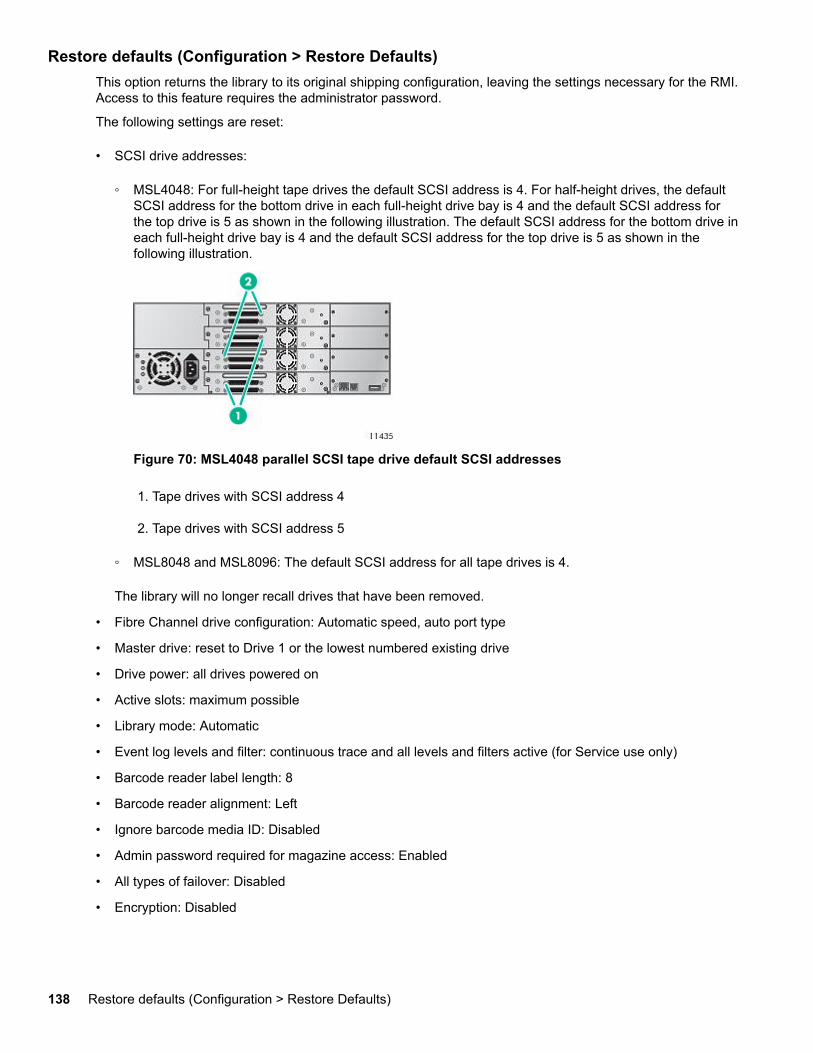
Restore defaults (Configuration > Restore Defaults)This option returns the library to its original shipping configuration, leaving the settings necessary for the RMI.Access to this feature requires the administrator password.
The following settings are reset:
• SCSI drive addresses:
◦ MSL4048: For full-height tape drives the default SCSI address is 4. For half-height drives, the defaultSCSI address for the bottom drive in each full-height drive bay is 4 and the default SCSI address forthe top drive is 5 as shown in the following illustration. The default SCSI address for the bottom drive ineach full-height drive bay is 4 and the default SCSI address for the top drive is 5 as shown in thefollowing illustration.
Figure 70: MSL4048 parallel SCSI tape drive default SCSI addresses
1. Tape drives with SCSI address 4
2. Tape drives with SCSI address 5
◦ MSL8048 and MSL8096: The default SCSI address for all tape drives is 4.
The library will no longer recall drives that have been removed.
• Fibre Channel drive configuration: Automatic speed, auto port type
• Master drive: reset to Drive 1 or the lowest numbered existing drive
• Drive power: all drives powered on
• Active slots: maximum possible
• Library mode: Automatic
• Event log levels and filter: continuous trace and all levels and filters active (for Service use only)
• Barcode reader label length: 8
• Barcode reader alignment: Left
• Ignore barcode media ID: Disabled
• Admin password required for magazine access: Enabled
• All types of failover: Disabled
• Encryption: Disabled
138 Restore defaults (Configuration > Restore Defaults)
NOTE:
Defaults will not be reset if encryption is enabled.
• HTTPS: Disabled
• Restricted Network Access: Enabled
• Error recovery: On
• Mailslot configuration: mailslot disabled
• Auto clean: disabled
• SNMP: disabled, but saved addresses do not change
• E-mail notification: disabled, but configurations retained
• License keys
The following settings are not reset:
• Administrator password
• Network settings (network is always enabled and the network addresses are retained)
• Date and time
IMPORTANT:
When the defaults are restored, the library will rediscover and renumber the tape drives from the bottomof the library up. If a tape drive was added between two other tape drives since the last time the driveswere discovered, that tape drive and the ones above it will be renumbered. You might need to updatethe configuration of the backup application when tape drives are renumbered.
Setting the library date and time (Configuration > Set Date and Time)This option sets the date and time used by the library to record events. Access to this feature requires theadministrator password.
NOTE:
Time is based on a 24-hour clock. There is no a.m. or p.m. designation. For example: 1:00 p.m. is 13:00.
Saving and restoring the library configuration (Configuration> Save/Restore)This option saves the library configuration to a USB flash drive and restores the configuration from the USBflash drive.
For a list of the configuration settings that are saved, see Default and restore defaults settings.
Operations menuThe Operations menu contains the following library operation options:
• Opening the mailslot (Operations > Open Mailslot) on page 140
• Unlocking, removing, and replacing magazines (Operations > Unlock Left/Right Magazines) onpage 131
Setting the library date and time (Configuration > Set Date and Time) 139
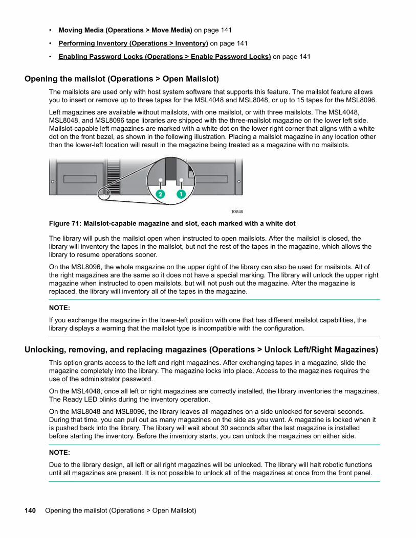
• Moving Media (Operations > Move Media) on page 141
• Performing Inventory (Operations > Inventory) on page 141
• Enabling Password Locks (Operations > Enable Password Locks) on page 141
Opening the mailslot (Operations > Open Mailslot)The mailslots are used only with host system software that supports this feature. The mailslot feature allowsyou to insert or remove up to three tapes for the MSL4048 and MSL8048, or up to 15 tapes for the MSL8096.
Left magazines are available without mailslots, with one mailslot, or with three mailslots. The MSL4048,MSL8048, and MSL8096 tape libraries are shipped with the three-mailslot magazine on the lower left side.Mailslot-capable left magazines are marked with a white dot on the lower right corner that aligns with a whitedot on the front bezel, as shown in the following illustration. Placing a mailslot magazine in any location otherthan the lower-left location will result in the magazine being treated as a magazine with no mailslots.
Figure 71: Mailslot-capable magazine and slot, each marked with a white dot
The library will push the mailslot open when instructed to open mailslots. After the mailslot is closed, thelibrary will inventory the tapes in the mailslot, but not the rest of the tapes in the magazine, which allows thelibrary to resume operations sooner.
On the MSL8096, the whole magazine on the upper right of the library can also be used for mailslots. All ofthe right magazines are the same so it does not have a special marking. The library will unlock the upper rightmagazine when instructed to open mailslots, but will not push out the magazine. After the magazine isreplaced, the library will inventory all of the tapes in the magazine.
NOTE:
If you exchange the magazine in the lower-left position with one that has different mailslot capabilities, thelibrary displays a warning that the mailslot type is incompatible with the configuration.
Unlocking, removing, and replacing magazines (Operations > Unlock Left/Right Magazines)This option grants access to the left and right magazines. After exchanging tapes in a magazine, slide themagazine completely into the library. The magazine locks into place. Access to the magazines requires theuse of the administrator password.
On the MSL4048, once all left or right magazines are correctly installed, the library inventories the magazines.The Ready LED blinks during the inventory operation.
On the MSL8048 and MSL8096, the library leaves all magazines on a side unlocked for several seconds.During that time, you can pull out as many magazines on the side as you want. A magazine is locked when itis pushed back into the library. The library will wait about 30 seconds after the last magazine is installedbefore starting the inventory. Before the inventory starts, you can unlock the magazines on either side.
NOTE:
Due to the library design, all left or all right magazines will be unlocked. The library will halt robotic functionsuntil all magazines are present. It is not possible to unlock all of the magazines at once from the front panel.
140 Opening the mailslot (Operations > Open Mailslot)
Moving Media (Operations > Move Media)This option instructs the library to move a cartridge from a tape drive, a tape slot in any magazine or a mailslotto any other location not already holding a tape. This option also lets you load and unload tape cartridges toand from the installed tape drives. To use this command, you must first select where you want to move thetape from (in one of the Source fields), and then indicate where you want to move the tape to (in one of theDestinations fields).
Source Type: This toggles between all available mailslot, magazines, and drives.
Source -> Source by Label: If appropriate, this toggles between available source cartridges. Only Fullsource slots are available for selection.
Destination Type: This toggles between all available destinations: Mailslot, Magazine, and Drive.
Destination: If appropriate, this option allows you to specify the cartridge destination. For a magazine, selecta slot. Only Empty destination slots are available for selection.
Access to the Move Media option requires the use of the administrator password.
Performing Inventory (Operations > Inventory)This option updates the inventory status of the library. The library checks each slot and drive for bar codesand determines if tapes are present or not.
NOTE:
This command is needed only if the inventory in the library is different than the inventory displayed on thefront panel, which would not happen under normal conditions.
Enabling Password Locks (Operations > Enable Password Locks)This option locks the restricted areas. This is typically used if the operator does not want to wait for the timeout to reset the locks. Power cycling or library Reset also resets the locks.
Support menuThe following Support menu options are available:
• Powering drives on and off (Support > Power on/off Drives) on page 141
• Cleaning the tape drive (Support > Clean Drive) on page 141
• Running tests (Support > Run Tests) on page 142
• Viewing logs (Support > View Logs) on page 142
• Updating library and drive firmware (Support > FW Upgrade) on page 142
• Force ejecting a drive (Support > Force Drive Eject) on page 144
• Rebooting the tape library (Support > Reboot) on page 144
Powering drives on and off (Support > Power on/off Drives)This option allows the powering up or down of a drive without interrupting power to the rest of the library andthe other drives. This is typically used when replacing one drive. Access to this feature requires theadministrator password.
Cleaning the tape drive (Support > Clean Drive)This option allows you to clean the drives. Access to this feature requires the administrator password.
Moving Media (Operations > Move Media) 141
When the Clean drive LED is on, the tape drive needs to be cleaned. Cleaning times can range from a fewseconds to a few minutes during which time the Ready LED blinks. Use only the designated cleaningcartridge for your tape drive model. All cartridges are available at http://www.hpe.com/info/storagemedia.
Use only Ultrium Universal cleaning cartridges.
IMPORTANT:
If the cleaning cartridge is not a valid cleaning cartridge, the LCD screen displays Invalid Tape and thecartridge is exported.
IMPORTANT:
If the Clean drive LED or the Media Attention LED (on load or unload) occurs when inserting the samecartridge after you have cleaned the drive, there might be a problem with that cartridge.
When using the OCP to clean the tape drive, import the cleaning cartridge into the mailslot or any other emptyslot before beginning the cleaning steps. If you would like to keep a cleaning cartridge in the library, thebackup software must manage tape drive cleaning or be configured to bypass the slot containing the cleaningcartridge.
The Clean drive option lets you load a cleaning tape into any active drive. To use this command, you mustfirst select the drive to be cleaned and then select where you want to load the cleaning tape from.
• Source Type: This toggles between all available sources: Mailslot, Magazine.
• Source/Source by Label: If appropriate, this toggles between available source cartridges. Barcode labelsbeginning with CLN are automatically displayed at the top of the list.
After cleaning, the library returns the cleaning cartridge to the original slot. If you loaded the cartridge from thefront panel, you should now unload it from that slot either by using the mailslot, or by removing the magazine.When the tape drive cleaning is complete, the Clean LED turns off (if previously on).
Running tests (Support > Run Tests)This option allows you to run a demo, a wellness test, or a slot to slot test and to specify the number of testcycles required. You can abort the test at any time, if necessary. Access to this feature requires theadministrator password. For more information about the wellness test, see The wellness test on page 163.
NOTE:
Abort is available only on the OCP. You cannot abort a test that has been started from the RMI.
Viewing logs (Support > View Logs)This option allows you to view the following logs: Error, Warning, Informational, Configuration, and All Eventspossible. Access to this feature requires the administrator password.
Updating library and drive firmware (Support > FW Upgrade)The tape library allows two types of firmware to be upgraded — one for the tape drives and the other for thetape library itself. You can upgrade both types of firmware from a USB flash drive, the RMI, or L&TT. You canalso upgrade drive firmware from a firmware upgrade tape.
The library only supports signed firmware image upgrades and downgrades. Once firmware that uses codesigning is loaded, the firmware will reject all unsigned images. If you attempt to load an unsigned firmwareimage, the RMI displays an invalid firmware version error message:
142 Running tests (Support > Run Tests)
If you see this message, download the latest signed firmware image from the MSL website at: http://www.hpe.com/info/msl
Using a USB flash drive to upgrade firmware (Support > FW Upgrade> By USB)This option allows you to upgrade tape library or tape drive firmware using a USB flash drive in the tapelibrary USB port on the back panel. No operations will be available until the upgrade completes. Access to thisfeature requires the administrator password.
Procedure
1. Download current firmware using Library & Tape Tools or from the Hewlett Packard Enterprise supportwebsite: http://www.hpe.com/support/storage. Copy the firmware onto the USB flash drive.
2. Insert the USB flash drive into the USB port on the back of the device.
3. From the Support menu, select FW Upgrade > By USB.
4. Select the target for the upgrade, which will be one of the tape drives or the library, and select the filenameof the firmware.
5. Click Upgrade.
6. When the upgrade is complete, remove the USB flash drive from the USB port.
Using Library & Tape Tools (L&TT) to update library and drive firmwareYou can download library and drive firmware using the L&TT diagnostic utility. This utility might already beinstalled on your server. If not, download it from http://www.hpe.com/support/TapeTools.
Online help and instructions are included with L&TT. The firmware download procedure involves these steps:
Procedure
1. Run the L&TT utility.
2. If prompted to download new firmware from the website, select Yes; otherwise, select Get Firmware fromWeb under the File menu.
3. Select the desired firmware revisions for the library that you would like to download firmware to, and thenclick Download. The firmware file is copied into the L&TT firmware folder.
4. Close the firmware window.
5. Select the library in the By Product device list tab, and then select the Firmware button. The latestrevision available for the library is automatically selected.
6. Click Start Update to update the firmware for the library.
Using a firmware upgrade tape to update drive firmware (Support> FW Upgrade > By Tape)This option allows the updating of drive code using a firmware upgrade tape. No operations will be availableuntil the update completes. Access to this feature requires the administrator password. To use this command,select the drive or drives to be upgraded, and then select where you want to load the firmware upgrade tapefrom.
• Source Type: This toggles between all available sources: magazines and drives.
• Source: This toggles between available source cartridges. You can select a specific slot (Source field) orspecify the firmware upgrade tape barcode (Source by Label field). Unlabeled tapes must be accessed bytheir slot number.
Operating the library 143
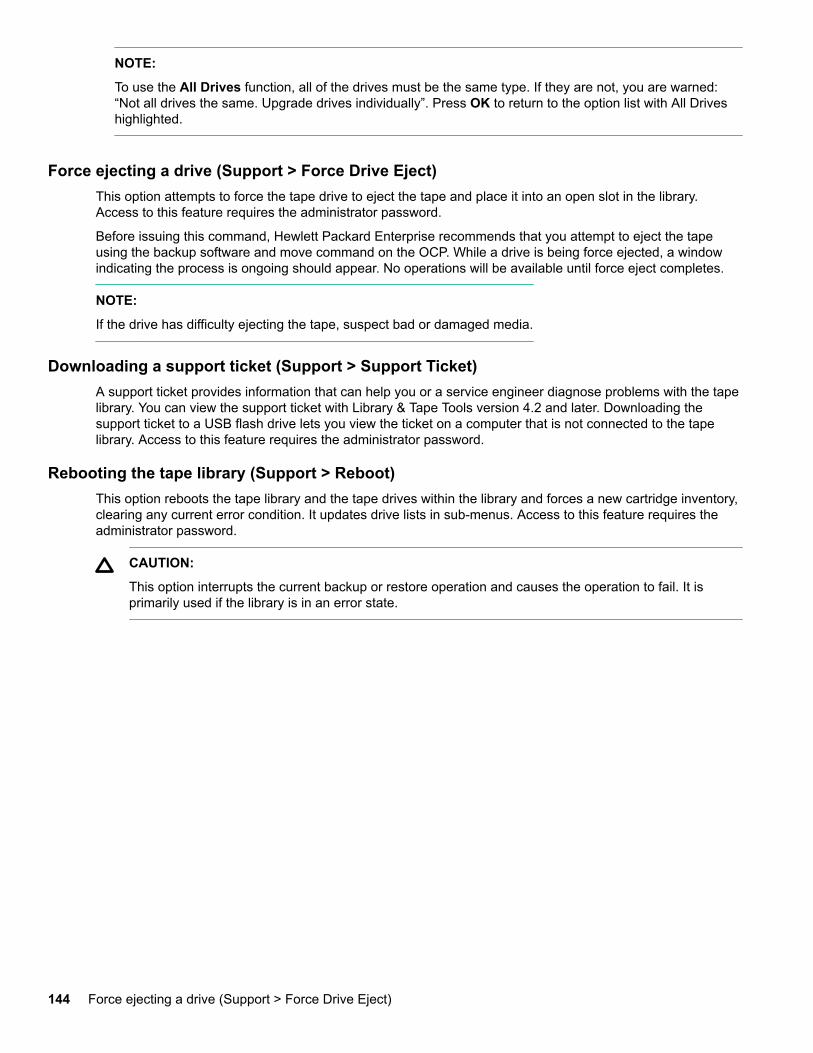
NOTE:
To use the All Drives function, all of the drives must be the same type. If they are not, you are warned:“Not all drives the same. Upgrade drives individually”. Press OK to return to the option list with All Driveshighlighted.
Force ejecting a drive (Support > Force Drive Eject)This option attempts to force the tape drive to eject the tape and place it into an open slot in the library.Access to this feature requires the administrator password.
Before issuing this command, Hewlett Packard Enterprise recommends that you attempt to eject the tapeusing the backup software and move command on the OCP. While a drive is being force ejected, a windowindicating the process is ongoing should appear. No operations will be available until force eject completes.
NOTE:
If the drive has difficulty ejecting the tape, suspect bad or damaged media.
Downloading a support ticket (Support > Support Ticket)A support ticket provides information that can help you or a service engineer diagnose problems with the tapelibrary. You can view the support ticket with Library & Tape Tools version 4.2 and later. Downloading thesupport ticket to a USB flash drive lets you view the ticket on a computer that is not connected to the tapelibrary. Access to this feature requires the administrator password.
Rebooting the tape library (Support > Reboot)This option reboots the tape library and the tape drives within the library and forces a new cartridge inventory,clearing any current error condition. It updates drive lists in sub-menus. Access to this feature requires theadministrator password.
CAUTION:
This option interrupts the current backup or restore operation and causes the operation to fail. It isprimarily used if the library is in an error state.
144 Force ejecting a drive (Support > Force Drive Eject)
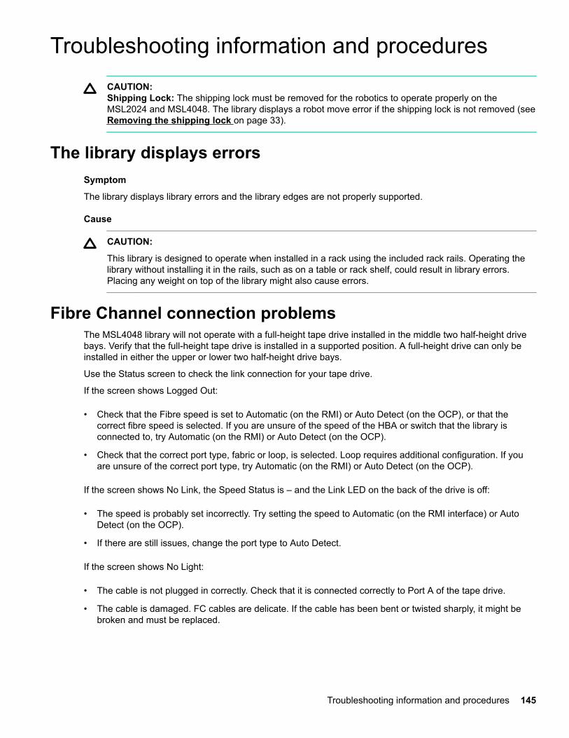
Troubleshooting information and proceduresCAUTION:Shipping Lock: The shipping lock must be removed for the robotics to operate properly on theMSL2024 and MSL4048. The library displays a robot move error if the shipping lock is not removed (see Removing the shipping lock on page 33).
The library displays errorsSymptom
The library displays library errors and the library edges are not properly supported.
Cause
CAUTION:
This library is designed to operate when installed in a rack using the included rack rails. Operating thelibrary without installing it in the rails, such as on a table or rack shelf, could result in library errors.Placing any weight on top of the library might also cause errors.
Fibre Channel connection problemsThe MSL4048 library will not operate with a full-height tape drive installed in the middle two half-height drivebays. Verify that the full-height tape drive is installed in a supported position. A full-height drive can only beinstalled in either the upper or lower two half-height drive bays.
Use the Status screen to check the link connection for your tape drive.
If the screen shows Logged Out:
• Check that the Fibre speed is set to Automatic (on the RMI) or Auto Detect (on the OCP), or that thecorrect fibre speed is selected. If you are unsure of the speed of the HBA or switch that the library isconnected to, try Automatic (on the RMI) or Auto Detect (on the OCP).
• Check that the correct port type, fabric or loop, is selected. Loop requires additional configuration. If youare unsure of the correct port type, try Automatic (on the RMI) or Auto Detect (on the OCP).
If the screen shows No Link, the Speed Status is – and the Link LED on the back of the drive is off:
• The speed is probably set incorrectly. Try setting the speed to Automatic (on the RMI interface) or AutoDetect (on the OCP).
• If there are still issues, change the port type to Auto Detect.
If the screen shows No Light:
• The cable is not plugged in correctly. Check that it is connected correctly to Port A of the tape drive.
• The cable is damaged. FC cables are delicate. If the cable has been bent or twisted sharply, it might bebroken and must be replaced.
Troubleshooting information and procedures 145
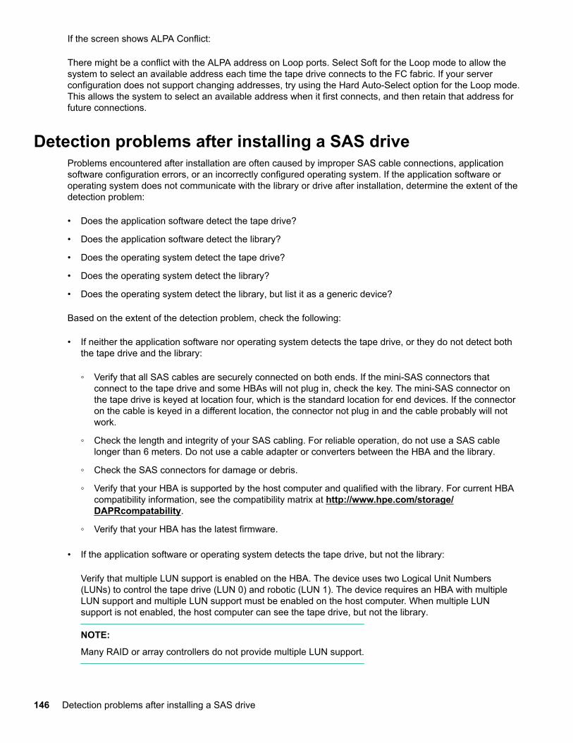
If the screen shows ALPA Conflict:
There might be a conflict with the ALPA address on Loop ports. Select Soft for the Loop mode to allow thesystem to select an available address each time the tape drive connects to the FC fabric. If your serverconfiguration does not support changing addresses, try using the Hard Auto-Select option for the Loop mode.This allows the system to select an available address when it first connects, and then retain that address forfuture connections.
Detection problems after installing a SAS driveProblems encountered after installation are often caused by improper SAS cable connections, applicationsoftware configuration errors, or an incorrectly configured operating system. If the application software oroperating system does not communicate with the library or drive after installation, determine the extent of thedetection problem:
• Does the application software detect the tape drive?
• Does the application software detect the library?
• Does the operating system detect the tape drive?
• Does the operating system detect the library?
• Does the operating system detect the library, but list it as a generic device?
Based on the extent of the detection problem, check the following:
• If neither the application software nor operating system detects the tape drive, or they do not detect boththe tape drive and the library:
◦ Verify that all SAS cables are securely connected on both ends. If the mini-SAS connectors thatconnect to the tape drive and some HBAs will not plug in, check the key. The mini-SAS connector onthe tape drive is keyed at location four, which is the standard location for end devices. If the connectoron the cable is keyed in a different location, the connector not plug in and the cable probably will notwork.
◦ Check the length and integrity of your SAS cabling. For reliable operation, do not use a SAS cablelonger than 6 meters. Do not use a cable adapter or converters between the HBA and the library.
◦ Check the SAS connectors for damage or debris.
◦ Verify that your HBA is supported by the host computer and qualified with the library. For current HBAcompatibility information, see the compatibility matrix at http://www.hpe.com/storage/DAPRcompatability.
◦ Verify that your HBA has the latest firmware.
• If the application software or operating system detects the tape drive, but not the library:
Verify that multiple LUN support is enabled on the HBA. The device uses two Logical Unit Numbers(LUNs) to control the tape drive (LUN 0) and robotic (LUN 1). The device requires an HBA with multipleLUN support and multiple LUN support must be enabled on the host computer. When multiple LUNsupport is not enabled, the host computer can see the tape drive, but not the library.
NOTE:
Many RAID or array controllers do not provide multiple LUN support.
146 Detection problems after installing a SAS drive
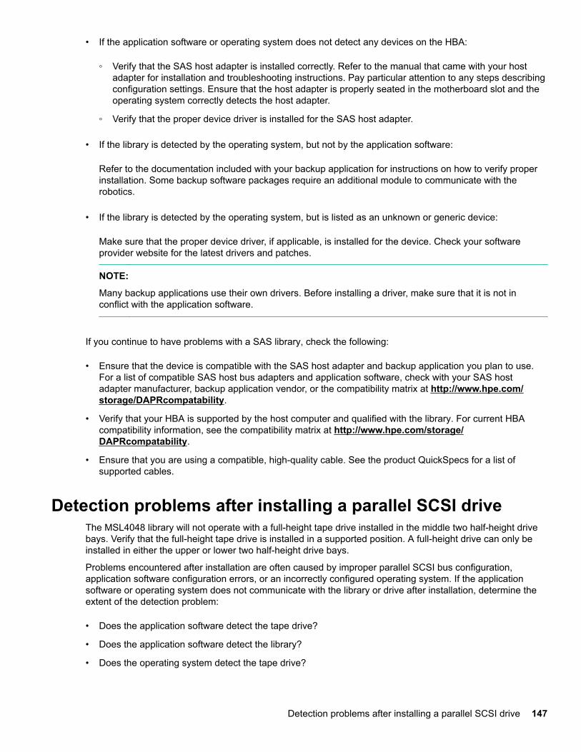
• If the application software or operating system does not detect any devices on the HBA:
◦ Verify that the SAS host adapter is installed correctly. Refer to the manual that came with your hostadapter for installation and troubleshooting instructions. Pay particular attention to any steps describingconfiguration settings. Ensure that the host adapter is properly seated in the motherboard slot and theoperating system correctly detects the host adapter.
◦ Verify that the proper device driver is installed for the SAS host adapter.
• If the library is detected by the operating system, but not by the application software:
Refer to the documentation included with your backup application for instructions on how to verify properinstallation. Some backup software packages require an additional module to communicate with therobotics.
• If the library is detected by the operating system, but is listed as an unknown or generic device:
Make sure that the proper device driver, if applicable, is installed for the device. Check your softwareprovider website for the latest drivers and patches.
NOTE:
Many backup applications use their own drivers. Before installing a driver, make sure that it is not inconflict with the application software.
If you continue to have problems with a SAS library, check the following:
• Ensure that the device is compatible with the SAS host adapter and backup application you plan to use.For a list of compatible SAS host bus adapters and application software, check with your SAS hostadapter manufacturer, backup application vendor, or the compatibility matrix at http://www.hpe.com/storage/DAPRcompatability.
• Verify that your HBA is supported by the host computer and qualified with the library. For current HBAcompatibility information, see the compatibility matrix at http://www.hpe.com/storage/DAPRcompatability.
• Ensure that you are using a compatible, high-quality cable. See the product QuickSpecs for a list ofsupported cables.
Detection problems after installing a parallel SCSI driveThe MSL4048 library will not operate with a full-height tape drive installed in the middle two half-height drivebays. Verify that the full-height tape drive is installed in a supported position. A full-height drive can only beinstalled in either the upper or lower two half-height drive bays.
Problems encountered after installation are often caused by improper parallel SCSI bus configuration,application software configuration errors, or an incorrectly configured operating system. If the applicationsoftware or operating system does not communicate with the library or drive after installation, determine theextent of the detection problem:
• Does the application software detect the tape drive?
• Does the application software detect the library?
• Does the operating system detect the tape drive?
Detection problems after installing a parallel SCSI drive 147
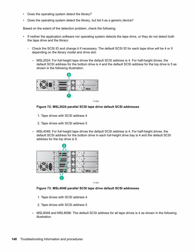
• Does the operating system detect the library?
• Does the operating system detect the library, but list it as a generic device?
Based on the extent of the detection problem, check the following:
• If neither the application software nor operating system detects the tape drive, or they do not detect boththe tape drive and the library:
◦ Check the SCSI ID and change it if necessary. The default SCSI ID for each tape drive will be 4 or 5depending on the library model and drive slot:
– MSL2024: For full-height tape drives the default SCSI address is 4. For half-height drives, thedefault SCSI address for the bottom drive is 4 and the default SCSI address for the top drive is 5 asshown in the following illustration.
Figure 72: MSL2024 parallel SCSI tape drive default SCSI addresses
1. Tape drives with SCSI address 4
2. Tape drives with SCSI address 5
– MSL4048: For full-height tape drives the default SCSI address is 4. For half-height drives, thedefault SCSI address for the bottom drive in each full-height drive bay is 4 and the default SCSIaddress for the top drive is 5.
Figure 73: MSL4048 parallel SCSI tape drive default SCSI addresses
1. Tape drives with SCSI address 4
2. Tape drives with SCSI address 5
– MSL8048 and MSL8096: The default SCSI address for all tape drives is 4 as shown in the followingillustration.
148 Troubleshooting information and procedures
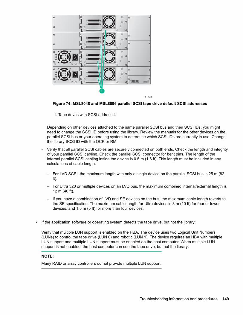
Figure 74: MSL8048 and MSL8096 parallel SCSI tape drive default SCSI addresses
1. Tape drives with SCSI address 4
Depending on other devices attached to the same parallel SCSI bus and their SCSI IDs, you mightneed to change the SCSI ID before using the library. Review the manuals for the other devices on theparallel SCSI bus or your operating system to determine which SCSI IDs are currently in use. Changethe library SCSI ID with the OCP or RMI.
◦ Verify that all parallel SCSI cables are securely connected on both ends. Check the length and integrityof your parallel SCSI cabling. Check the parallel SCSI connector for bent pins. The length of theinternal parallel SCSI cabling inside the device is 0.5 m (1.6 ft). This length must be included in anycalculations of cable length.
– For LVD SCSI, the maximum length with only a single device on the parallel SCSI bus is 25 m (82ft).
– For Ultra 320 or multiple devices on an LVD bus, the maximum combined internal/external length is12 m (40 ft).
– If you have a combination of LVD and SE devices on the bus, the maximum cable length reverts tothe SE specification. The maximum cable length for Ultra devices is 3 m (10 ft) for four or fewerdevices, and 1.5 m (5 ft) for more than four devices.
• If the application software or operating system detects the tape drive, but not the library:
Verify that multiple LUN support is enabled on the HBA. The device uses two Logical Unit Numbers(LUNs) to control the tape drive (LUN 0) and robotic (LUN 1). The device requires an HBA with multipleLUN support and multiple LUN support must be enabled on the host computer. When multiple LUNsupport is not enabled, the host computer can see the tape drive, but not the library.
NOTE:
Many RAID or array controllers do not provide multiple LUN support.
Troubleshooting information and procedures 149
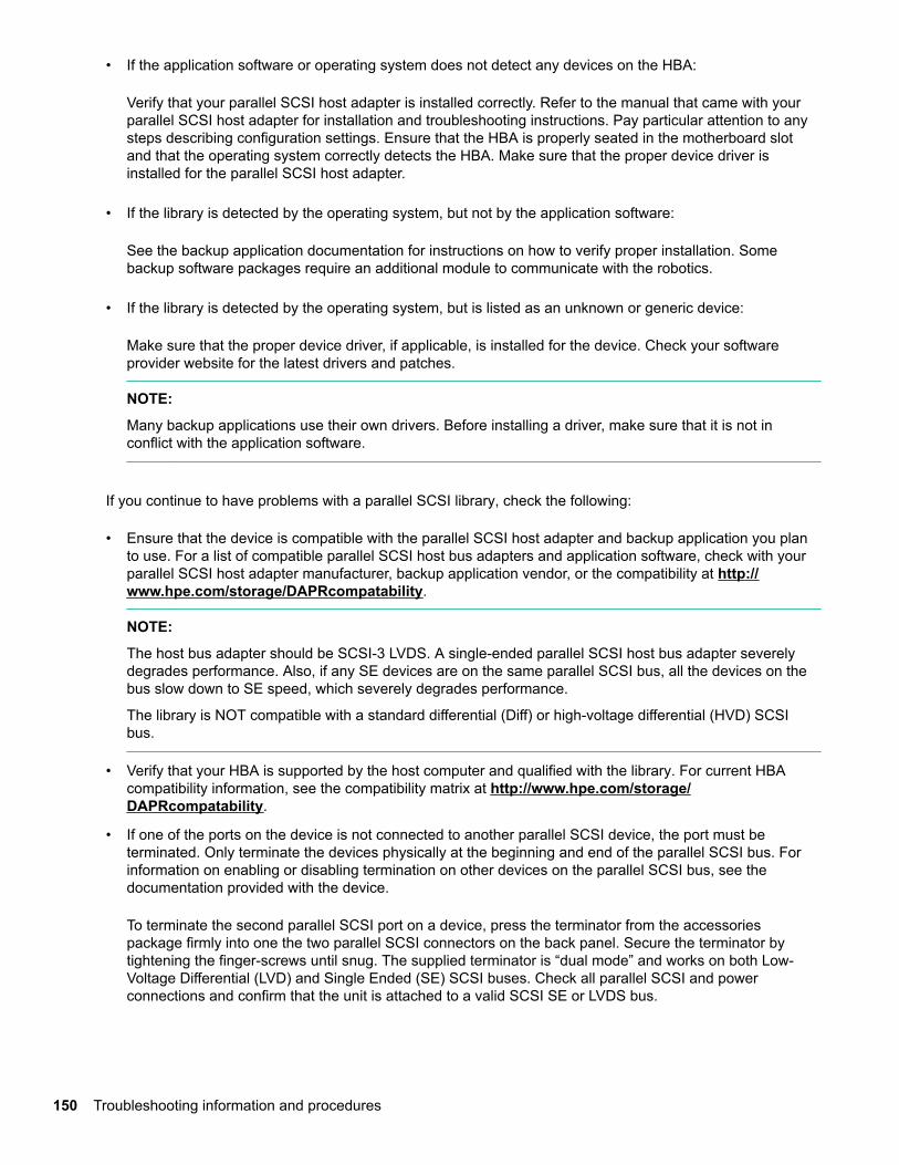
• If the application software or operating system does not detect any devices on the HBA:
Verify that your parallel SCSI host adapter is installed correctly. Refer to the manual that came with yourparallel SCSI host adapter for installation and troubleshooting instructions. Pay particular attention to anysteps describing configuration settings. Ensure that the HBA is properly seated in the motherboard slotand that the operating system correctly detects the HBA. Make sure that the proper device driver isinstalled for the parallel SCSI host adapter.
• If the library is detected by the operating system, but not by the application software:
See the backup application documentation for instructions on how to verify proper installation. Somebackup software packages require an additional module to communicate with the robotics.
• If the library is detected by the operating system, but is listed as an unknown or generic device:
Make sure that the proper device driver, if applicable, is installed for the device. Check your softwareprovider website for the latest drivers and patches.
NOTE:
Many backup applications use their own drivers. Before installing a driver, make sure that it is not inconflict with the application software.
If you continue to have problems with a parallel SCSI library, check the following:
• Ensure that the device is compatible with the parallel SCSI host adapter and backup application you planto use. For a list of compatible parallel SCSI host bus adapters and application software, check with yourparallel SCSI host adapter manufacturer, backup application vendor, or the compatibility at http://www.hpe.com/storage/DAPRcompatability.
NOTE:
The host bus adapter should be SCSI-3 LVDS. A single-ended parallel SCSI host bus adapter severelydegrades performance. Also, if any SE devices are on the same parallel SCSI bus, all the devices on thebus slow down to SE speed, which severely degrades performance.
The library is NOT compatible with a standard differential (Diff) or high-voltage differential (HVD) SCSIbus.
• Verify that your HBA is supported by the host computer and qualified with the library. For current HBAcompatibility information, see the compatibility matrix at http://www.hpe.com/storage/DAPRcompatability.
• If one of the ports on the device is not connected to another parallel SCSI device, the port must beterminated. Only terminate the devices physically at the beginning and end of the parallel SCSI bus. Forinformation on enabling or disabling termination on other devices on the parallel SCSI bus, see thedocumentation provided with the device.
To terminate the second parallel SCSI port on a device, press the terminator from the accessoriespackage firmly into one the two parallel SCSI connectors on the back panel. Secure the terminator bytightening the finger-screws until snug. The supplied terminator is “dual mode” and works on both Low-Voltage Differential (LVD) and Single Ended (SE) SCSI buses. Check all parallel SCSI and powerconnections and confirm that the unit is attached to a valid SCSI SE or LVDS bus.
150 Troubleshooting information and procedures
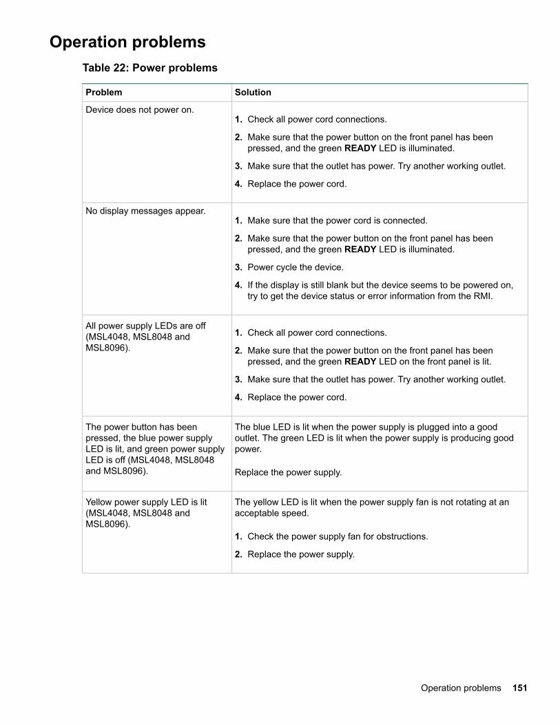
Operation problemsTable 22: Power problems
Problem Solution
Device does not power on.1. Check all power cord connections.
2. Make sure that the power button on the front panel has beenpressed, and the green READY LED is illuminated.
3. Make sure that the outlet has power. Try another working outlet.
4. Replace the power cord.
No display messages appear.1. Make sure that the power cord is connected.
2. Make sure that the power button on the front panel has beenpressed, and the green READY LED is illuminated.
3. Power cycle the device.
4. If the display is still blank but the device seems to be powered on,try to get the device status or error information from the RMI.
All power supply LEDs are off(MSL4048, MSL8048 andMSL8096).
1. Check all power cord connections.
2. Make sure that the power button on the front panel has beenpressed, and the green READY LED on the front panel is lit.
3. Make sure that the outlet has power. Try another working outlet.
4. Replace the power cord.
The power button has beenpressed, the blue power supplyLED is lit, and green power supplyLED is off (MSL4048, MSL8048and MSL8096).
The blue LED is lit when the power supply is plugged into a goodoutlet. The green LED is lit when the power supply is producing goodpower.
Replace the power supply.
Yellow power supply LED is lit(MSL4048, MSL8048 andMSL8096).
The yellow LED is lit when the power supply fan is not rotating at anacceptable speed.
1. Check the power supply fan for obstructions.
2. Replace the power supply.
Operation problems 151
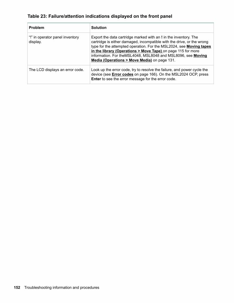
Table 23: Failure/attention indications displayed on the front panel
Problem Solution
“!” in operator panel inventorydisplay.
Export the data cartridge marked with an ! in the inventory. Thecartridge is either damaged, incompatible with the drive, or the wrongtype for the attempted operation. For the MSL2024, see Moving tapesin the library (Operations > Move Tape) on page 115 for moreinformation. For theMSL4048, MSL8048 and MSL8096, see MovingMedia (Operations > Move Media) on page 131.
The LCD displays an error code. Look up the error code, try to resolve the failure, and power cycle thedevice (see Error codes on page 166). On the MSL2024 OCP, pressEnter to see the error message for the error code.
152 Troubleshooting information and procedures
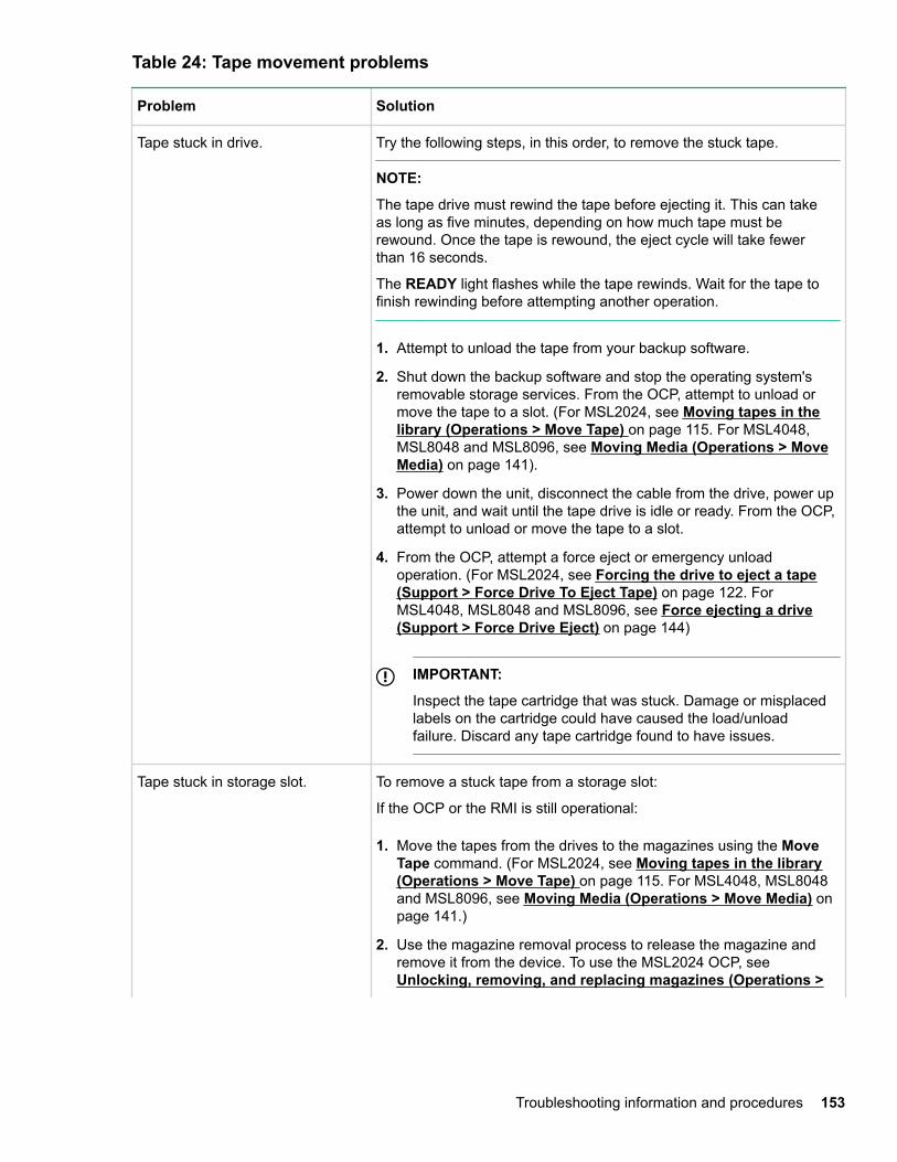
Table 24: Tape movement problems
Problem Solution
Tape stuck in drive. Try the following steps, in this order, to remove the stuck tape.
NOTE:
The tape drive must rewind the tape before ejecting it. This can takeas long as five minutes, depending on how much tape must berewound. Once the tape is rewound, the eject cycle will take fewerthan 16 seconds.
The READY light flashes while the tape rewinds. Wait for the tape tofinish rewinding before attempting another operation.
1. Attempt to unload the tape from your backup software.
2. Shut down the backup software and stop the operating system'sremovable storage services. From the OCP, attempt to unload ormove the tape to a slot. (For MSL2024, see Moving tapes in thelibrary (Operations > Move Tape) on page 115. For MSL4048,MSL8048 and MSL8096, see Moving Media (Operations > MoveMedia) on page 141).
3. Power down the unit, disconnect the cable from the drive, power upthe unit, and wait until the tape drive is idle or ready. From the OCP,attempt to unload or move the tape to a slot.
4. From the OCP, attempt a force eject or emergency unloadoperation. (For MSL2024, see Forcing the drive to eject a tape(Support > Force Drive To Eject Tape) on page 122. ForMSL4048, MSL8048 and MSL8096, see Force ejecting a drive(Support > Force Drive Eject) on page 144)
IMPORTANT:
Inspect the tape cartridge that was stuck. Damage or misplacedlabels on the cartridge could have caused the load/unloadfailure. Discard any tape cartridge found to have issues.
Tape stuck in storage slot. To remove a stuck tape from a storage slot:
If the OCP or the RMI is still operational:
1. Move the tapes from the drives to the magazines using the MoveTape command. (For MSL2024, see Moving tapes in the library(Operations > Move Tape) on page 115. For MSL4048, MSL8048and MSL8096, see Moving Media (Operations > Move Media) onpage 141.)
2. Use the magazine removal process to release the magazine andremove it from the device. To use the MSL2024 OCP, see Unlocking, removing, and replacing magazines (Operations >
Troubleshooting information and procedures 153
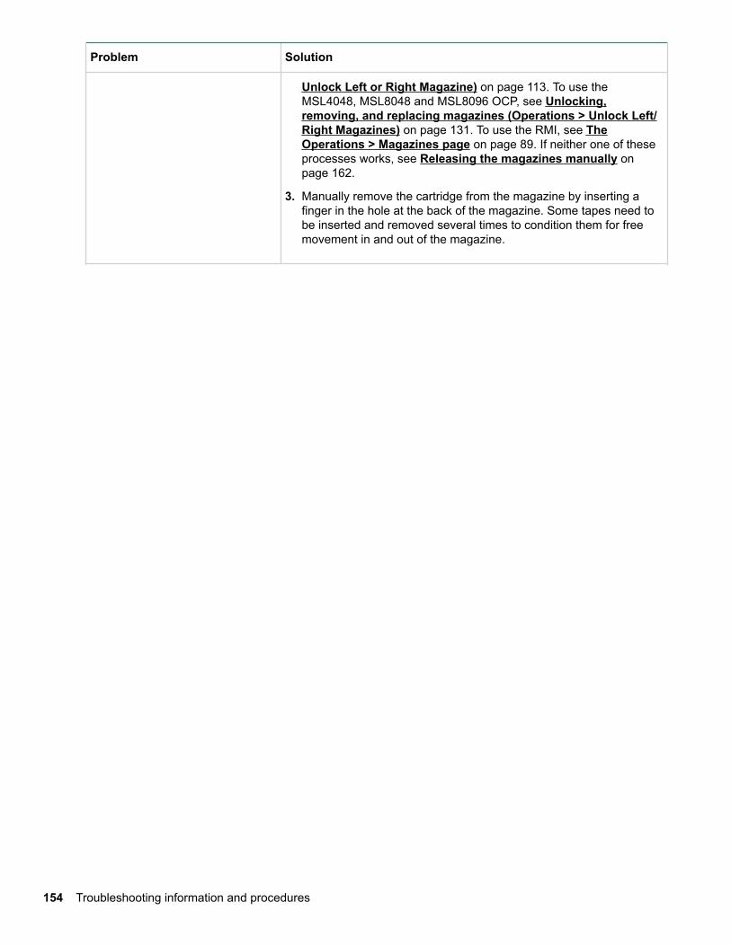
Problem Solution
Unlock Left or Right Magazine) on page 113. To use theMSL4048, MSL8048 and MSL8096 OCP, see Unlocking,removing, and replacing magazines (Operations > Unlock Left/Right Magazines) on page 131. To use the RMI, see TheOperations > Magazines page on page 89. If neither one of theseprocesses works, see Releasing the magazines manually onpage 162.
3. Manually remove the cartridge from the magazine by inserting afinger in the hole at the back of the magazine. Some tapes need tobe inserted and removed several times to condition them for freemovement in and out of the magazine.
154 Troubleshooting information and procedures
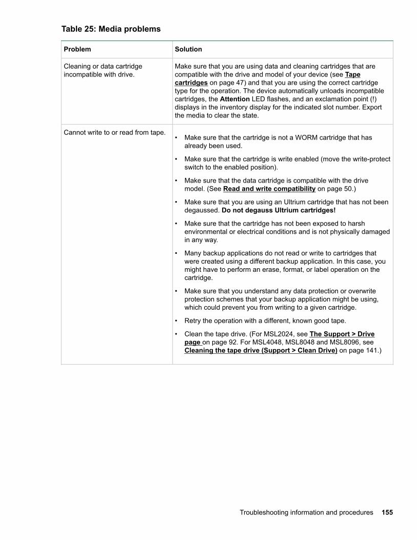
Table 25: Media problems
Problem Solution
Cleaning or data cartridgeincompatible with drive.
Make sure that you are using data and cleaning cartridges that arecompatible with the drive and model of your device (see Tapecartridges on page 47) and that you are using the correct cartridgetype for the operation. The device automatically unloads incompatiblecartridges, the Attention LED flashes, and an exclamation point (!)displays in the inventory display for the indicated slot number. Exportthe media to clear the state.
Cannot write to or read from tape.• Make sure that the cartridge is not a WORM cartridge that has
already been used.
• Make sure that the cartridge is write enabled (move the write-protectswitch to the enabled position).
• Make sure that the data cartridge is compatible with the drivemodel. (See Read and write compatibility on page 50.)
• Make sure that you are using an Ultrium cartridge that has not beendegaussed. Do not degauss Ultrium cartridges!
• Make sure that the cartridge has not been exposed to harshenvironmental or electrical conditions and is not physically damagedin any way.
• Many backup applications do not read or write to cartridges thatwere created using a different backup application. In this case, youmight have to perform an erase, format, or label operation on thecartridge.
• Make sure that you understand any data protection or overwriteprotection schemes that your backup application might be using,which could prevent you from writing to a given cartridge.
• Retry the operation with a different, known good tape.
• Clean the tape drive. (For MSL2024, see The Support > Drivepage on page 92. For MSL4048, MSL8048 and MSL8096, see Cleaning the tape drive (Support > Clean Drive) on page 141.)
Troubleshooting information and procedures 155
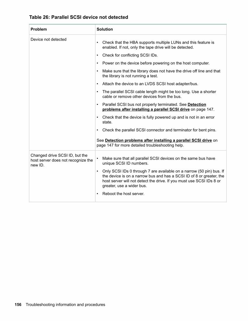
Table 26: Parallel SCSI device not detected
Problem Solution
Device not detected• Check that the HBA supports multiple LUNs and this feature is
enabled. If not, only the tape drive will be detected.
• Check for conflicting SCSI IDs.
• Power on the device before powering on the host computer.
• Make sure that the library does not have the drive off line and thatthe library is not running a test.
• Attach the device to an LVDS SCSI host adapter/bus.
• The parallel SCSI cable length might be too long. Use a shortercable or remove other devices from the bus.
• Parallel SCSI bus not properly terminated. See Detectionproblems after installing a parallel SCSI drive on page 147.
• Check that the device is fully powered up and is not in an errorstate.
• Check the parallel SCSI connector and terminator for bent pins.
See Detection problems after installing a parallel SCSI drive onpage 147 for more detailed troubleshooting help.
Changed drive SCSI ID, but thehost server does not recognize thenew ID.
• Make sure that all parallel SCSI devices on the same bus haveunique SCSI ID numbers.
• Only SCSI IDs 0 through 7 are available on a narrow (50 pin) bus. Ifthe device is on a narrow bus and has a SCSI ID of 8 or greater, thehost server will not detect the drive. If you must use SCSI IDs 8 orgreater, use a wider bus.
• Reboot the host server.
156 Troubleshooting information and procedures
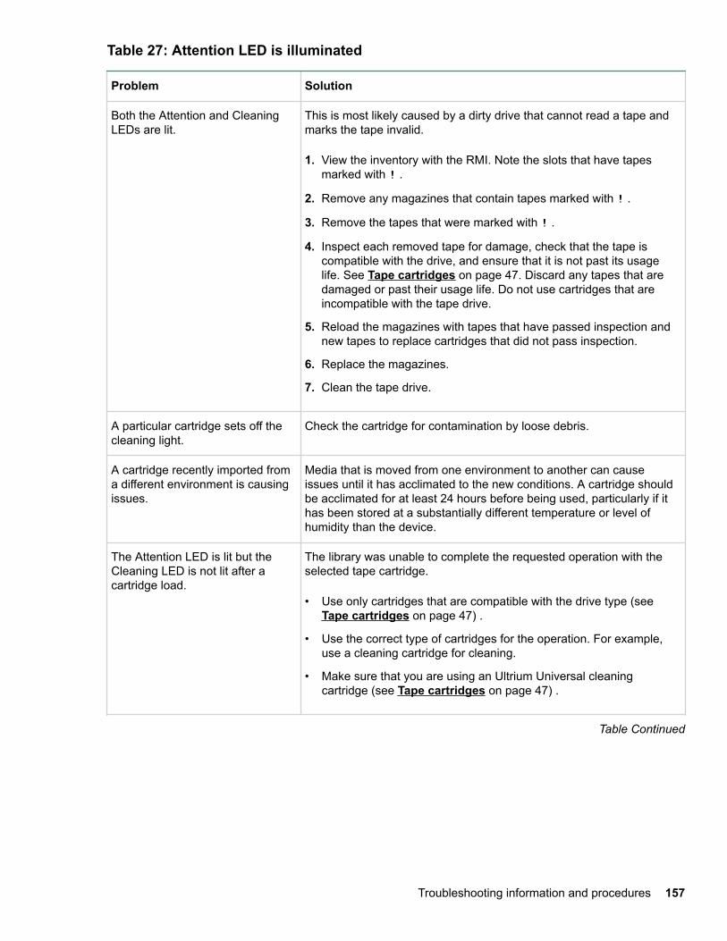
Table 27: Attention LED is illuminated
Problem Solution
Both the Attention and CleaningLEDs are lit.
This is most likely caused by a dirty drive that cannot read a tape andmarks the tape invalid.
1. View the inventory with the RMI. Note the slots that have tapesmarked with ! .
2. Remove any magazines that contain tapes marked with ! .
3. Remove the tapes that were marked with ! .
4. Inspect each removed tape for damage, check that the tape iscompatible with the drive, and ensure that it is not past its usagelife. See Tape cartridges on page 47. Discard any tapes that aredamaged or past their usage life. Do not use cartridges that areincompatible with the tape drive.
5. Reload the magazines with tapes that have passed inspection andnew tapes to replace cartridges that did not pass inspection.
6. Replace the magazines.
7. Clean the tape drive.
A particular cartridge sets off thecleaning light.
Check the cartridge for contamination by loose debris.
A cartridge recently imported froma different environment is causingissues.
Media that is moved from one environment to another can causeissues until it has acclimated to the new conditions. A cartridge shouldbe acclimated for at least 24 hours before being used, particularly if ithas been stored at a substantially different temperature or level ofhumidity than the device.
The Attention LED is lit but theCleaning LED is not lit after acartridge load.
The library was unable to complete the requested operation with theselected tape cartridge.
• Use only cartridges that are compatible with the drive type (see Tape cartridges on page 47) .
• Use the correct type of cartridges for the operation. For example,use a cleaning cartridge for cleaning.
• Make sure that you are using an Ultrium Universal cleaningcartridge (see Tape cartridges on page 47) .
Table Continued
Troubleshooting information and procedures 157
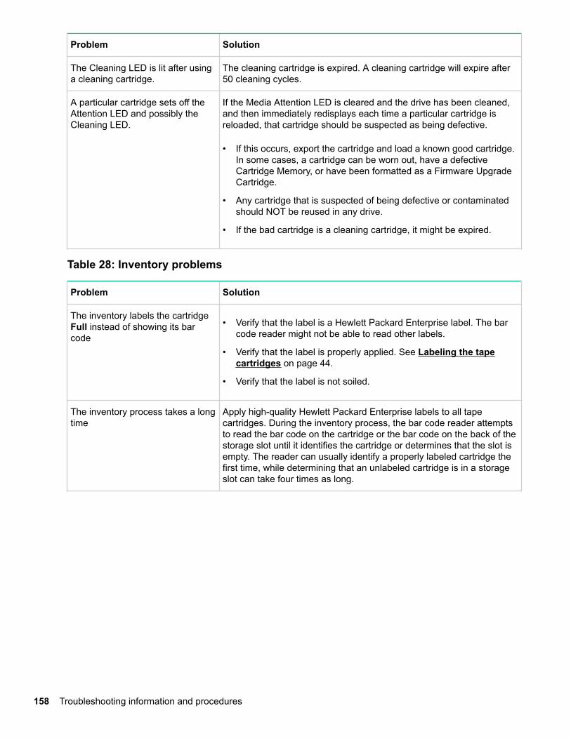
Problem Solution
The Cleaning LED is lit after usinga cleaning cartridge.
The cleaning cartridge is expired. A cleaning cartridge will expire after50 cleaning cycles.
A particular cartridge sets off theAttention LED and possibly theCleaning LED.
If the Media Attention LED is cleared and the drive has been cleaned,and then immediately redisplays each time a particular cartridge isreloaded, that cartridge should be suspected as being defective.
• If this occurs, export the cartridge and load a known good cartridge.In some cases, a cartridge can be worn out, have a defectiveCartridge Memory, or have been formatted as a Firmware UpgradeCartridge.
• Any cartridge that is suspected of being defective or contaminatedshould NOT be reused in any drive.
• If the bad cartridge is a cleaning cartridge, it might be expired.
Table 28: Inventory problems
Problem Solution
The inventory labels the cartridgeFull instead of showing its barcode
• Verify that the label is a Hewlett Packard Enterprise label. The barcode reader might not be able to read other labels.
• Verify that the label is properly applied. See Labeling the tapecartridges on page 44.
• Verify that the label is not soiled.
The inventory process takes a longtime
Apply high-quality Hewlett Packard Enterprise labels to all tapecartridges. During the inventory process, the bar code reader attemptsto read the bar code on the cartridge or the bar code on the back of thestorage slot until it identifies the cartridge or determines that the slot isempty. The reader can usually identify a properly labeled cartridge thefirst time, while determining that an unlabeled cartridge is in a storageslot can take four times as long.
158 Troubleshooting information and procedures
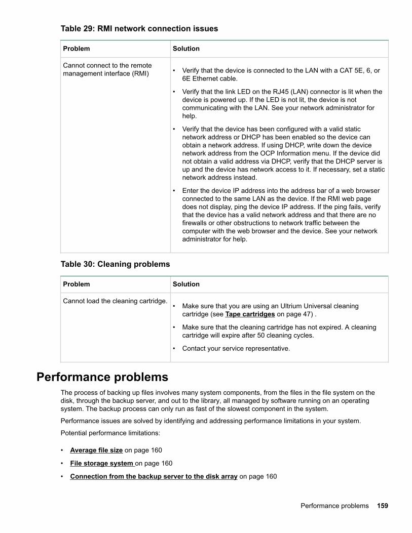
Table 29: RMI network connection issues
Problem Solution
Cannot connect to the remotemanagement interface (RMI) • Verify that the device is connected to the LAN with a CAT 5E, 6, or
6E Ethernet cable.
• Verify that the link LED on the RJ45 (LAN) connector is lit when thedevice is powered up. If the LED is not lit, the device is notcommunicating with the LAN. See your network administrator forhelp.
• Verify that the device has been configured with a valid staticnetwork address or DHCP has been enabled so the device canobtain a network address. If using DHCP, write down the devicenetwork address from the OCP Information menu. If the device didnot obtain a valid address via DHCP, verify that the DHCP server isup and the device has network access to it. If necessary, set a staticnetwork address instead.
• Enter the device IP address into the address bar of a web browserconnected to the same LAN as the device. If the RMI web pagedoes not display, ping the device IP address. If the ping fails, verifythat the device has a valid network address and that there are nofirewalls or other obstructions to network traffic between thecomputer with the web browser and the device. See your networkadministrator for help.
Table 30: Cleaning problems
Problem Solution
Cannot load the cleaning cartridge.• Make sure that you are using an Ultrium Universal cleaning
cartridge (see Tape cartridges on page 47) .
• Make sure that the cleaning cartridge has not expired. A cleaningcartridge will expire after 50 cleaning cycles.
• Contact your service representative.
Performance problemsThe process of backing up files involves many system components, from the files in the file system on thedisk, through the backup server, and out to the library, all managed by software running on an operatingsystem. The backup process can only run as fast of the slowest component in the system.
Performance issues are solved by identifying and addressing performance limitations in your system.
Potential performance limitations:
• Average file size on page 160
• File storage system on page 160
• Connection from the backup server to the disk array on page 160
Performance problems 159
• Backup/archive server on page 160
• Backup/archive software and method on page 161
• Connection from the archive/backup host server to the library on page 161
• Data cartridges on page 161
• Tape drive read or write performance seems slow on page 161
You can use the L&TT system performance test to assess the performance of simulated backup and restoreoperations. For information on downloading and using L&TT, see Diagnosing problems with Library &Tape Tools on page 211.
Average file sizeThe hard drive must seek to the position of a file before it can start reading. The more time the disks areseeking to files, the lower the performance. Therefore, if the average file size is small, the read performancewill be lower.
To determine the average file size, divide the size of the backup by the number of files.
If the average file size is small (64 KB or less), consider using a sequential, image, or block backup methodthat backs up the whole hard drive or LUN image instead of individual files. The trade-off for using one ofthese methods is that you might only be able to restore the entire image instead of individual files.
NOTE:
File fragmentation will also cause excessive drive seeking, which lowers performance, so ensure that files areregularly defragmented.
File storage systemThe file storage system determines the organization of the files on the disks. Using RAID controllers to spreadfiles over multiple disks can improve performance because some disks can be seeking while others arereading. Storing files on a single non-RAID disk results in the slowest performance while storing files on ahigh-end disk array results in the fastest performance.
Converting standalone disks to RAID can improve performance.
Ensure that the file systems being backed up have no or minimal fragmentation.
Connection from the backup server to the disk arrayThe connection between the host server and the disks determines how much data can be transferred from thedisks to the host computer at a time. A connection with insufficient bandwidth cannot provide enough data forthe tape drives to write at full speed. For optimum performance, the storage subsystem must be able toprovide data at the tape drive maximum transfer rate.
Backup systems using a lower speed Ethernet network should use multiple network connections.
Backup/archive serverThe backup server must have enough RAM and processor power to transfer the files from the disk to the tapedrive while also running the backup or archive software and any other processes.
Check the RAM and processor usage during a backup operation. If they are operating at capacity, addingRAM or processor capability can improve performance.
160 Average file size
Backup/archive software and methodEach backup method has its own impact on performance, depending on how well it can keep data streamingto the tape drive. In most cases, native applications do not have the features required to maximizeperformance for LTO tape drives. Hewlett Packard Enterprise recommends using a full-featured backup orarchive application with this library.
File-by-file backup or archive methods provide the best restore performance if you only need to restoreindividual files. However, if the average file size is small, file-by-file methods will significantly reduceperformance.
Disk image, flash, or sequential backup methods provide the fastest performance because they back up anentire disk, partition, or LUN, which minimizes disk seeking. The disadvantage is that backup and restoreoperations work on an entire disk, partition, or LUN. You might not be able to back up a subset of files orrestore a single file. If you can restore a single file, the restore process will be slow.
Database backup performance will vary based on the use model. To improve performance when backing updata from a database:
• Use specific backup agents for the database.
• Use the latest versions of the databases.
• Do not back up individual mailboxes.
• Do not back up specific records or do a record-by-record backup.
• Do not back up when the database is in heavy use.
Connection from the archive/backup host server to the libraryFor the best performance, the connection from the host server to the library must have enough bandwidth toprovide enough data to keep the tape drive streaming. Current LTO tape drives take advantage of some ofthe fastest interfaces available so the type of interface used to connect the library to the host server is notlikely to be the cause of a performance issue. However, issues with cables and connectors can limitperformance.
Verify that the system is using cables that are listed in the QuickSpecs, are in good condition, and do notexceed recommended cable lengths.
Data cartridgesThe type and condition of the data cartridges also affect backup performance. For best performance, useHewlett Packard Enterprise cartridges that are the same LTO generation as the tape drives. If you suspect aperformance issue related to data cartridges, use the L&TT media assessment test to evaluate the conditionof the data cartridges.
Tape drive read or write performance seems slow
Symptom
Tape drive read or write is slower than expected.
Cause
If the tape drive is not properly secured to the chassis or the library is not properly secured to the rack,vibration may cause slow read or write performance. Vibration could come from the cooling fan or externalsources.
Backup/archive software and method 161
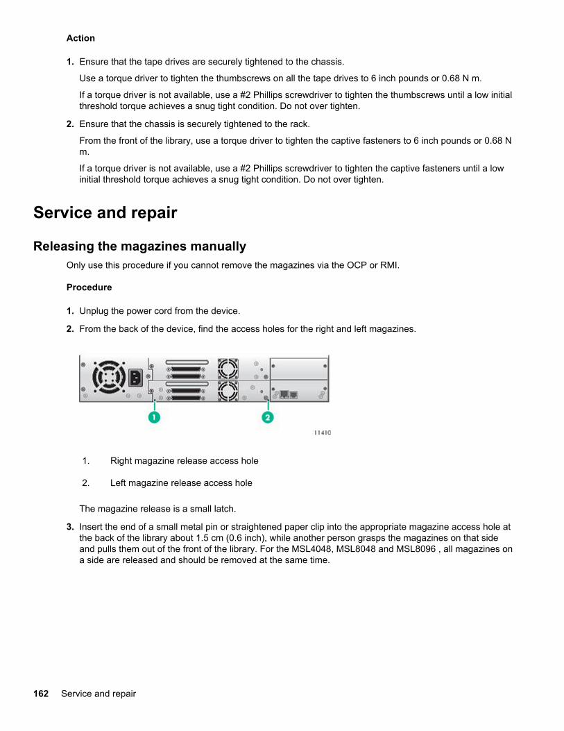
Action
1. Ensure that the tape drives are securely tightened to the chassis.
Use a torque driver to tighten the thumbscrews on all the tape drives to 6 inch pounds or 0.68 N m.
If a torque driver is not available, use a #2 Phillips screwdriver to tighten the thumbscrews until a low initialthreshold torque achieves a snug tight condition. Do not over tighten.
2. Ensure that the chassis is securely tightened to the rack.
From the front of the library, use a torque driver to tighten the captive fasteners to 6 inch pounds or 0.68 Nm.
If a torque driver is not available, use a #2 Phillips screwdriver to tighten the captive fasteners until a lowinitial threshold torque achieves a snug tight condition. Do not over tighten.
Service and repair
Releasing the magazines manuallyOnly use this procedure if you cannot remove the magazines via the OCP or RMI.
Procedure
1. Unplug the power cord from the device.
2. From the back of the device, find the access holes for the right and left magazines.
1. Right magazine release access hole
2. Left magazine release access hole
The magazine release is a small latch.
3. Insert the end of a small metal pin or straightened paper clip into the appropriate magazine access hole atthe back of the library about 1.5 cm (0.6 inch), while another person grasps the magazines on that sideand pulls them out of the front of the library. For the MSL4048, MSL8048 and MSL8096 , all magazines ona side are released and should be removed at the same time.
162 Service and repair
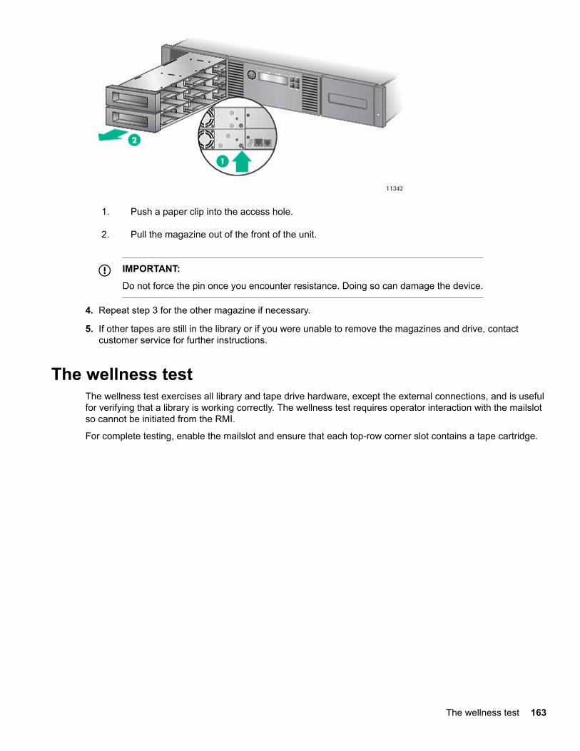
1. Push a paper clip into the access hole.
2. Pull the magazine out of the front of the unit.
IMPORTANT:
Do not force the pin once you encounter resistance. Doing so can damage the device.
4. Repeat step 3 for the other magazine if necessary.
5. If other tapes are still in the library or if you were unable to remove the magazines and drive, contactcustomer service for further instructions.
The wellness testThe wellness test exercises all library and tape drive hardware, except the external connections, and is usefulfor verifying that a library is working correctly. The wellness test requires operator interaction with the mailslotso cannot be initiated from the RMI.
For complete testing, enable the mailslot and ensure that each top-row corner slot contains a tape cartridge.
The wellness test 163
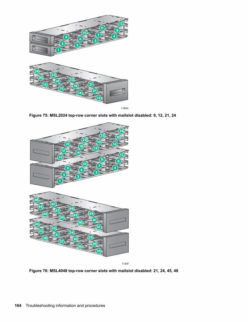
Figure 75: MSL2024 top-row corner slots with mailslot disabled: 9, 12, 21, 24
Figure 76: MSL4048 top-row corner slots with mailslot disabled: 21, 24, 45, 48
164 Troubleshooting information and procedures
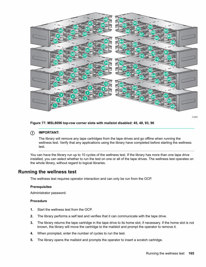
Figure 77: MSL8096 top-row corner slots with mailslot disabled: 45, 48, 93, 96
IMPORTANT:
The library will remove any tape cartridges from the tape drives and go offline when running thewellness test. Verify that any applications using the library have completed before starting the wellnesstest.
You can have the library run up to 10 cycles of the wellness test. If the library has more than one tape driveinstalled, you can select whether to run the test on one or all of the tape drives. The wellness test operates onthe whole library, without regard to logical libraries.
Running the wellness testThe wellness test requires operator interaction and can only be run from the OCP.
Prerequisites
Administrator password.
Procedure
1. Start the wellness test from the OCP.
2. The library performs a self test and verifies that it can communicate with the tape drive.
3. The library returns the tape cartridge in the tape drive to its home slot, if necessary. If the home slot is notknown, the library will move the cartridge to the mailslot and prompt the operator to remove it.
4. When prompted, enter the number of cycles to run the test.
5. The library opens the mailslot and prompts the operator to insert a scratch cartridge.
Running the wellness test 165
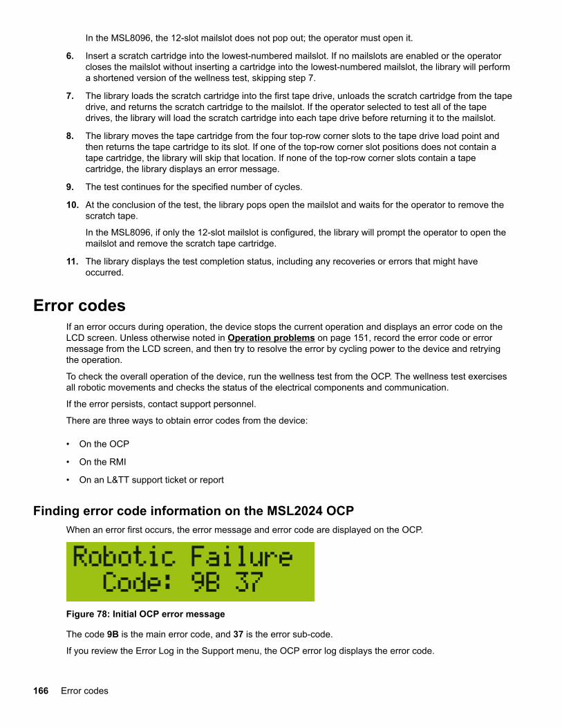
In the MSL8096, the 12-slot mailslot does not pop out; the operator must open it.
6. Insert a scratch cartridge into the lowest-numbered mailslot. If no mailslots are enabled or the operatorcloses the mailslot without inserting a cartridge into the lowest-numbered mailslot, the library will performa shortened version of the wellness test, skipping step 7.
7. The library loads the scratch cartridge into the first tape drive, unloads the scratch cartridge from the tapedrive, and returns the scratch cartridge to the mailslot. If the operator selected to test all of the tapedrives, the library will load the scratch cartridge into each tape drive before returning it to the mailslot.
8. The library moves the tape cartridge from the four top-row corner slots to the tape drive load point andthen returns the tape cartridge to its slot. If one of the top-row corner slot positions does not contain atape cartridge, the library will skip that location. If none of the top-row corner slots contain a tapecartridge, the library displays an error message.
9. The test continues for the specified number of cycles.
10. At the conclusion of the test, the library pops open the mailslot and waits for the operator to remove thescratch tape.
In the MSL8096, if only the 12-slot mailslot is configured, the library will prompt the operator to open themailslot and remove the scratch tape cartridge.
11. The library displays the test completion status, including any recoveries or errors that might haveoccurred.
Error codesIf an error occurs during operation, the device stops the current operation and displays an error code on theLCD screen. Unless otherwise noted in Operation problems on page 151, record the error code or errormessage from the LCD screen, and then try to resolve the error by cycling power to the device and retryingthe operation.
To check the overall operation of the device, run the wellness test from the OCP. The wellness test exercisesall robotic movements and checks the status of the electrical components and communication.
If the error persists, contact support personnel.
There are three ways to obtain error codes from the device:
• On the OCP
• On the RMI
• On an L&TT support ticket or report
Finding error code information on the MSL2024 OCPWhen an error first occurs, the error message and error code are displayed on the OCP.
Figure 78: Initial OCP error message
The code 9B is the main error code, and 37 is the error sub-code.
If you review the Error Log in the Support menu, the OCP error log displays the error code.
166 Error codes
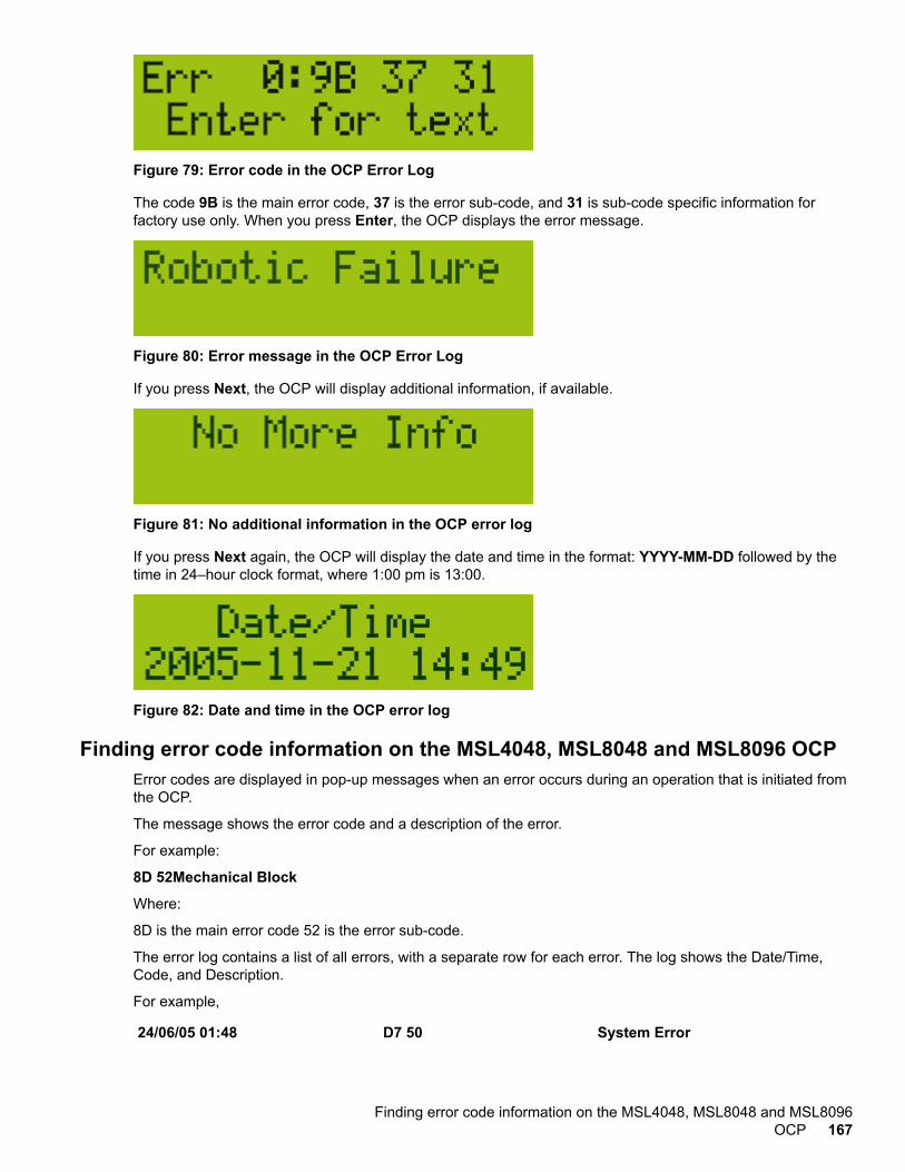
Figure 79: Error code in the OCP Error Log
The code 9B is the main error code, 37 is the error sub-code, and 31 is sub-code specific information forfactory use only. When you press Enter, the OCP displays the error message.
Figure 80: Error message in the OCP Error Log
If you press Next, the OCP will display additional information, if available.
Figure 81: No additional information in the OCP error log
If you press Next again, the OCP will display the date and time in the format: YYYY-MM-DD followed by thetime in 24–hour clock format, where 1:00 pm is 13:00.
Figure 82: Date and time in the OCP error log
Finding error code information on the MSL4048, MSL8048 and MSL8096 OCPError codes are displayed in pop-up messages when an error occurs during an operation that is initiated fromthe OCP.
The message shows the error code and a description of the error.
For example:
8D 52Mechanical Block
Where:
8D is the main error code 52 is the error sub-code.
The error log contains a list of all errors, with a separate row for each error. The log shows the Date/Time,Code, and Description.
For example,
24/06/05 01:48 D7 50 System Error
Finding error code information on the MSL4048, MSL8048 and MSL8096OCP 167
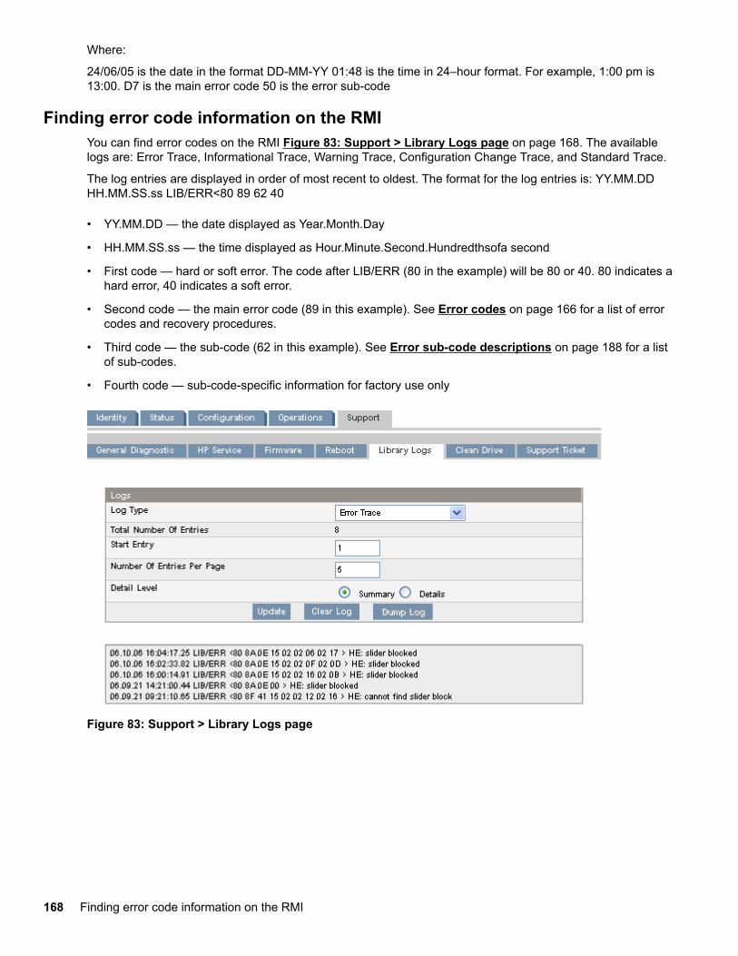
Where:
24/06/05 is the date in the format DD-MM-YY 01:48 is the time in 24–hour format. For example, 1:00 pm is13:00. D7 is the main error code 50 is the error sub-code
Finding error code information on the RMIYou can find error codes on the RMI Figure 83: Support > Library Logs page on page 168. The availablelogs are: Error Trace, Informational Trace, Warning Trace, Configuration Change Trace, and Standard Trace.
The log entries are displayed in order of most recent to oldest. The format for the log entries is: YY.MM.DDHH.MM.SS.ss LIB/ERR<80 89 62 40
• YY.MM.DD — the date displayed as Year.Month.Day
• HH.MM.SS.ss — the time displayed as Hour.Minute.Second.Hundredthsofa second
• First code — hard or soft error. The code after LIB/ERR (80 in the example) will be 80 or 40. 80 indicates ahard error, 40 indicates a soft error.
• Second code — the main error code (89 in this example). See Error codes on page 166 for a list of errorcodes and recovery procedures.
• Third code — the sub-code (62 in this example). See Error sub-code descriptions on page 188 for a listof sub-codes.
• Fourth code — sub-code-specific information for factory use only
Figure 83: Support > Library Logs page
168 Finding error code information on the RMI
Generating a report or support ticket from L&TT
Procedure
1. In the L&TT By Product or By Connection tab, select the device from the device list.
2. Click the Health button on the main toolbar to generate and display a standard report, or click the Supportbutton on the main toolbar to display the Support screen for additional report or support ticket options.
Downloading a support ticket from the library
TIP:
Each support ticket downloaded from the RMI will only contain information for the library itself or onedrive. To capture all support information, download a ticket from the library and from each drive. Togenerate a consolidated support ticket with all support data in a single compressed file, download thesupport ticket with L&TT.
Procedure
• From the RMI Support > Support ticketscreen, click Download.
• Insert a USB flash drive into the USB port on the rear panel and then from the OCP, select Downloadsupport ticket to USB.
Viewing a downloaded support ticket
Procedure
1. From the L&TT File menu, select Load Support Ticket.
2. Select the support ticket file in the browser.
Finding error code information on an L&TT support ticket or reportAn L&TT support ticket or report contains detailed information about the device configuration, along witherrors and warnings. The support ticket and report contain the same information. The report is easier to read,but must be generated and read on the host computer. The support ticket can be downloaded from the deviceand then viewed on any computer with L&TT installed.
The top of the support ticket contains basic configuration information about the library.
Generating a report or support ticket from L&TT 169
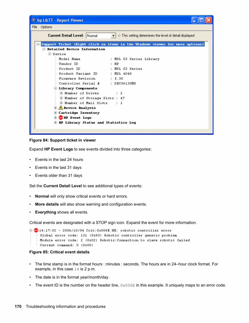
Figure 84: Support ticket in viewer
Expand HP Event Logs to see events divided into three categories:
• Events in the last 24 hours
• Events in the last 31 days
• Events older than 31 days
Set the Current Detail Level to see additional types of events:
• Normal will only show critical events or hard errors.
• More details will also show warning and configuration events.
• Everything shows all events.
Critical events are designated with a STOP sign icon. Expand the event for more information.
Figure 85: Critical event details
• The time stamp is in the format hours : minutes : seconds. The hours are in 24–hour clock format. Forexample, in this case 14 is 2 p.m.
• The date is in the format year/month/day.
• The event ID is the number on the header line, 0x006E in this example. It uniquely maps to an error code.
170 Troubleshooting information and procedures
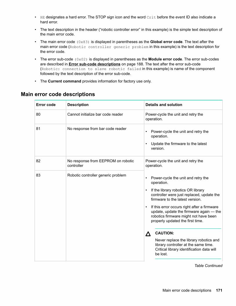
• HE designates a hard error. The STOP sign icon and the word Crit before the event ID also indicate ahard error.
• The text description in the header (“robotic controller error” in this example) is the simple text description ofthe main error code.
• The main error code (0x83) is displayed in parentheses as the Global error code. The text after themain error code (Robotic controller generic problem in this example) is the text description forthe error code.
• The error sub-code (0x02) is displayed in parentheses as the Module error code. The error sub-codesare described in Error sub-code descriptions on page 188. The text after the error sub-code(Robotic: connection to slave robotic failed in this example) is name of the componentfollowed by the text description of the error sub-code.
• The Current command provides information for factory use only.
Main error code descriptions
Error code Description Details and solution
80 Cannot initialize bar code reader Power-cycle the unit and retry theoperation.
81 No response from bar code reader• Power-cycle the unit and retry the
operation.
• Update the firmware to the latestversion.
82 No response from EEPROM on roboticcontroller
Power-cycle the unit and retry theoperation.
83 Robotic controller generic problem• Power-cycle the unit and retry the
operation.
• If the library robotics OR librarycontroller were just replaced, update thefirmware to the latest version.
• If this error occurs right after a firmwareupdate, update the firmware again — therobotics firmware might not have beenproperly updated the first time.
CAUTION:
Never replace the library robotics andlibrary controller at the same time.Critical library identification data willbe lost.
Table Continued
Main error code descriptions 171
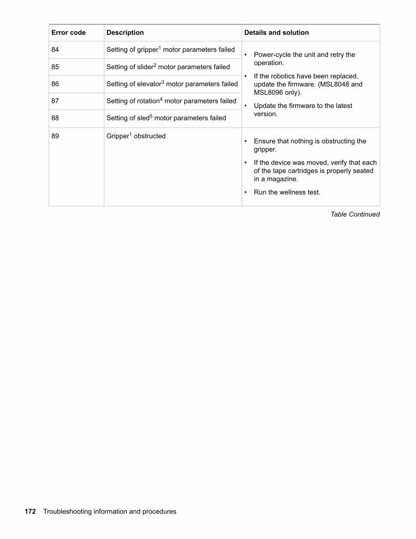
Error code Description Details and solution
84 Setting of gripper1 motor parameters failed• Power-cycle the unit and retry the
operation.
• If the robotics have been replaced,update the firmware. (MSL8048 andMSL8096 only).
• Update the firmware to the latestversion.
85 Setting of slider2 motor parameters failed
86 Setting of elevator3 motor parameters failed
87 Setting of rotation4 motor parameters failed
88 Setting of sled5 motor parameters failed
89 Gripper1 obstructed• Ensure that nothing is obstructing the
gripper.
• If the device was moved, verify that eachof the tape cartridges is properly seatedin a magazine.
• Run the wellness test.
Table Continued
172 Troubleshooting information and procedures
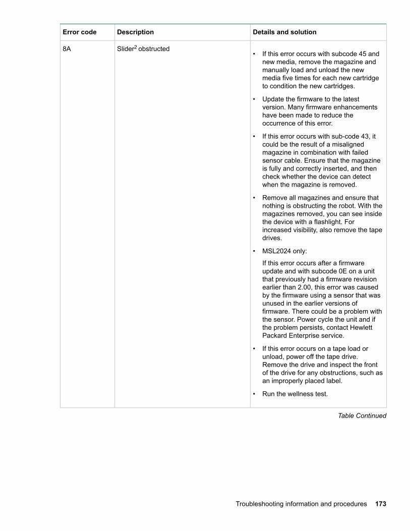
Error code Description Details and solution
8A Slider2 obstructed• If this error occurs with subcode 45 and
new media, remove the magazine andmanually load and unload the newmedia five times for each new cartridgeto condition the new cartridges.
• Update the firmware to the latestversion. Many firmware enhancementshave been made to reduce theoccurrence of this error.
• If this error occurs with sub-code 43, itcould be the result of a misalignedmagazine in combination with failedsensor cable. Ensure that the magazineis fully and correctly inserted, and thencheck whether the device can detectwhen the magazine is removed.
• Remove all magazines and ensure thatnothing is obstructing the robot. With themagazines removed, you can see insidethe device with a flashlight. Forincreased visibility, also remove the tapedrives.
• MSL2024 only:
If this error occurs after a firmwareupdate and with subcode 0E on a unitthat previously had a firmware revisionearlier than 2.00, this error was causedby the firmware using a sensor that wasunused in the earlier versions offirmware. There could be a problem withthe sensor. Power cycle the unit and ifthe problem persists, contact HewlettPackard Enterprise service.
• If this error occurs on a tape load orunload, power off the tape drive.Remove the drive and inspect the frontof the drive for any obstructions, such asan improperly placed label.
• Run the wellness test.
Table Continued
Troubleshooting information and procedures 173
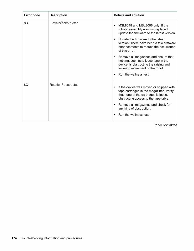
Error code Description Details and solution
8B Elevator3 obstructed• MSL8048 and MSL8096 only: If the
robotic assembly was just replaced,update the firmware to the latest version.
• Update the firmware to the latestversion. There have been a few firmwareenhancements to reduce the occurrenceof this error.
• Remove all magazines and ensure thatnothing, such as a loose tape in thedevice, is obstructing the raising andlowering movement of the robot.
• Run the wellness test.
8C Rotation4 obstructed• If the device was moved or shipped with
tape cartridges in the magazines, verifythat none of the cartridges is loose,obstructing access to the tape drive.
• Remove all magazines and check forany kind of obstruction.
• Run the wellness test.
Table Continued
174 Troubleshooting information and procedures
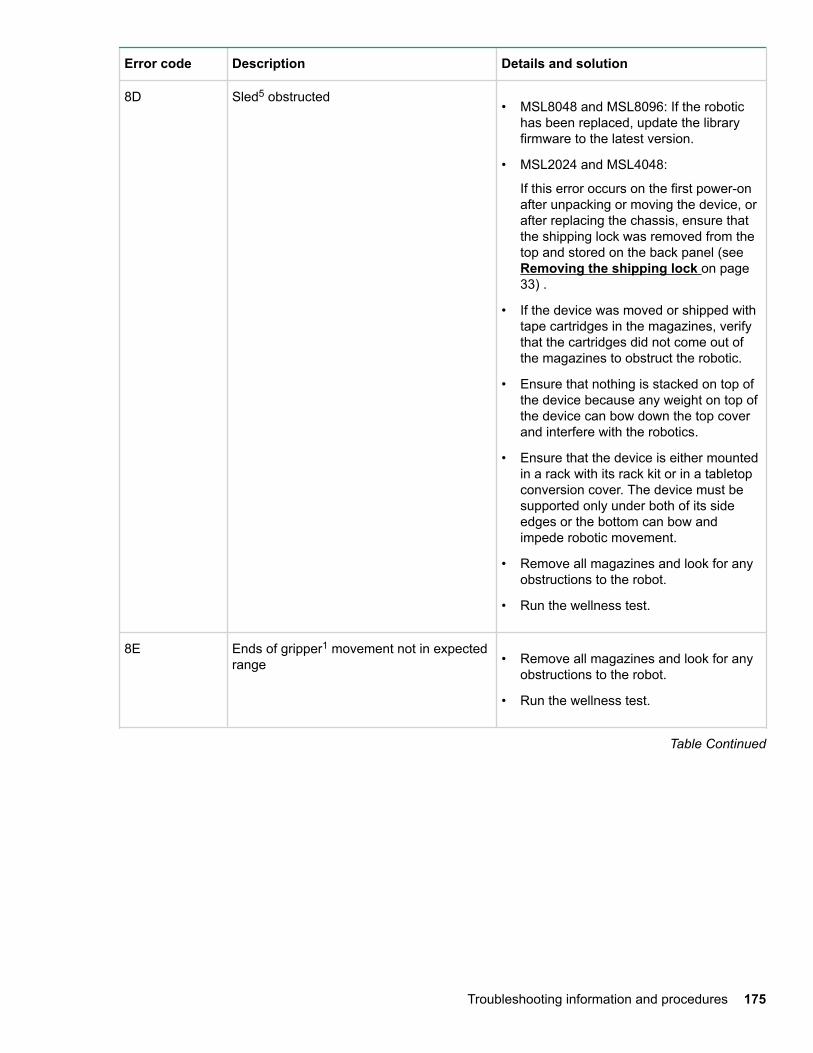
Error code Description Details and solution
8D Sled5 obstructed• MSL8048 and MSL8096: If the robotic
has been replaced, update the libraryfirmware to the latest version.
• MSL2024 and MSL4048:
If this error occurs on the first power-onafter unpacking or moving the device, orafter replacing the chassis, ensure thatthe shipping lock was removed from thetop and stored on the back panel (see Removing the shipping lock on page33) .
• If the device was moved or shipped withtape cartridges in the magazines, verifythat the cartridges did not come out ofthe magazines to obstruct the robotic.
• Ensure that nothing is stacked on top ofthe device because any weight on top ofthe device can bow down the top coverand interfere with the robotics.
• Ensure that the device is either mountedin a rack with its rack kit or in a tabletopconversion cover. The device must besupported only under both of its sideedges or the bottom can bow andimpede robotic movement.
• Remove all magazines and look for anyobstructions to the robot.
• Run the wellness test.
8E Ends of gripper1 movement not in expectedrange • Remove all magazines and look for any
obstructions to the robot.
• Run the wellness test.
Table Continued
Troubleshooting information and procedures 175
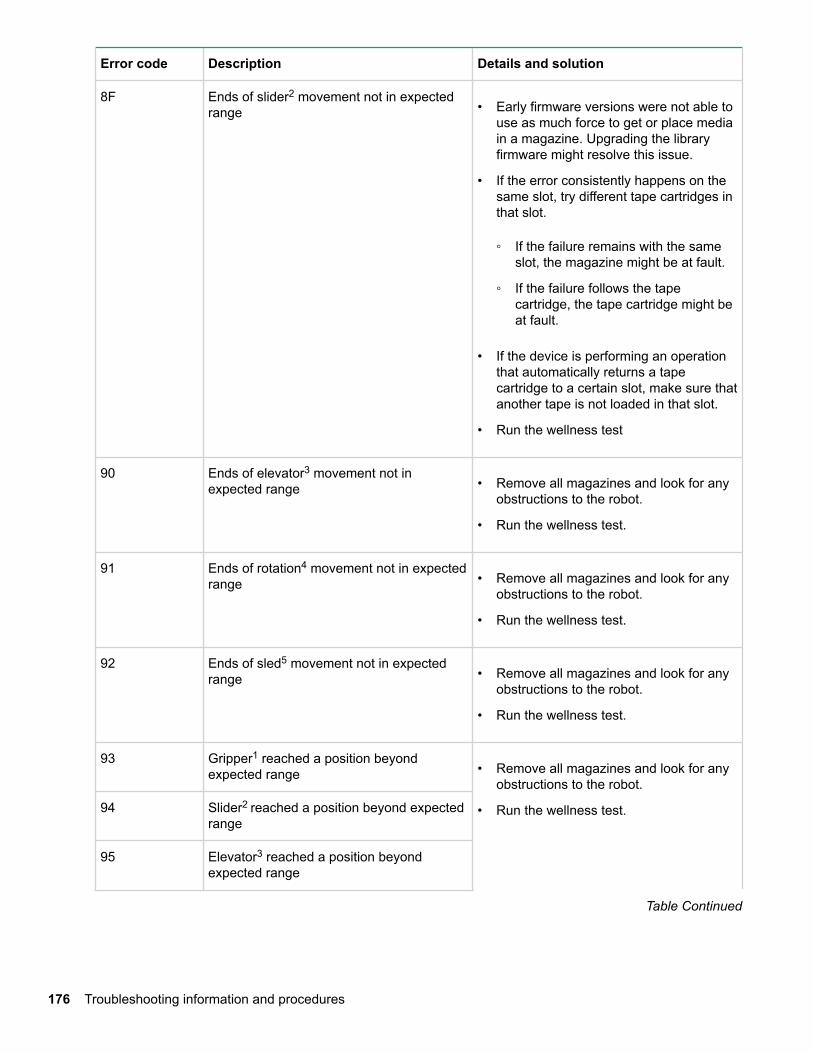
Error code Description Details and solution
8F Ends of slider2 movement not in expectedrange • Early firmware versions were not able to
use as much force to get or place mediain a magazine. Upgrading the libraryfirmware might resolve this issue.
• If the error consistently happens on thesame slot, try different tape cartridges inthat slot.
◦ If the failure remains with the sameslot, the magazine might be at fault.
◦ If the failure follows the tapecartridge, the tape cartridge might beat fault.
• If the device is performing an operationthat automatically returns a tapecartridge to a certain slot, make sure thatanother tape is not loaded in that slot.
• Run the wellness test
90 Ends of elevator3 movement not inexpected range • Remove all magazines and look for any
obstructions to the robot.
• Run the wellness test.
91 Ends of rotation4 movement not in expectedrange • Remove all magazines and look for any
obstructions to the robot.
• Run the wellness test.
92 Ends of sled5 movement not in expectedrange • Remove all magazines and look for any
obstructions to the robot.
• Run the wellness test.
93 Gripper1 reached a position beyondexpected range • Remove all magazines and look for any
obstructions to the robot.
• Run the wellness test.94 Slider2 reached a position beyond expectedrange
95 Elevator3 reached a position beyondexpected range
Table Continued
176 Troubleshooting information and procedures
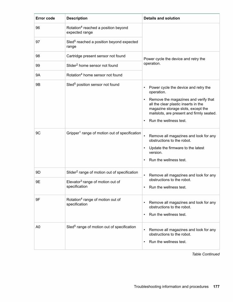
Error code Description Details and solution
96 Rotation4 reached a position beyondexpected range
97 Sled5 reached a position beyond expectedrange
98 Cartridge present sensor not foundPower cycle the device and retry theoperation.99 Slider2 home sensor not found
9A Rotation4 home sensor not found
9B Sled5 position sensor not found• Power cycle the device and retry the
operation.
• Remove the magazines and verify thatall the clear plastic inserts in themagazine storage slots, except themailslots, are present and firmly seated.
• Run the wellness test.
9C Gripper1 range of motion out of specification• Remove all magazines and look for any
obstructions to the robot.
• Update the firmware to the latestversion.
• Run the wellness test.
9D Slider2 range of motion out of specification• Remove all magazines and look for any
obstructions to the robot.
• Run the wellness test.9E Elevator3 range of motion out of
specification
9F Rotation4 range of motion out ofspecification • Remove all magazines and look for any
obstructions to the robot.
• Run the wellness test.
A0 Sled5 range of motion out of specification• Remove all magazines and look for any
obstructions to the robot.
• Run the wellness test.
Table Continued
Troubleshooting information and procedures 177
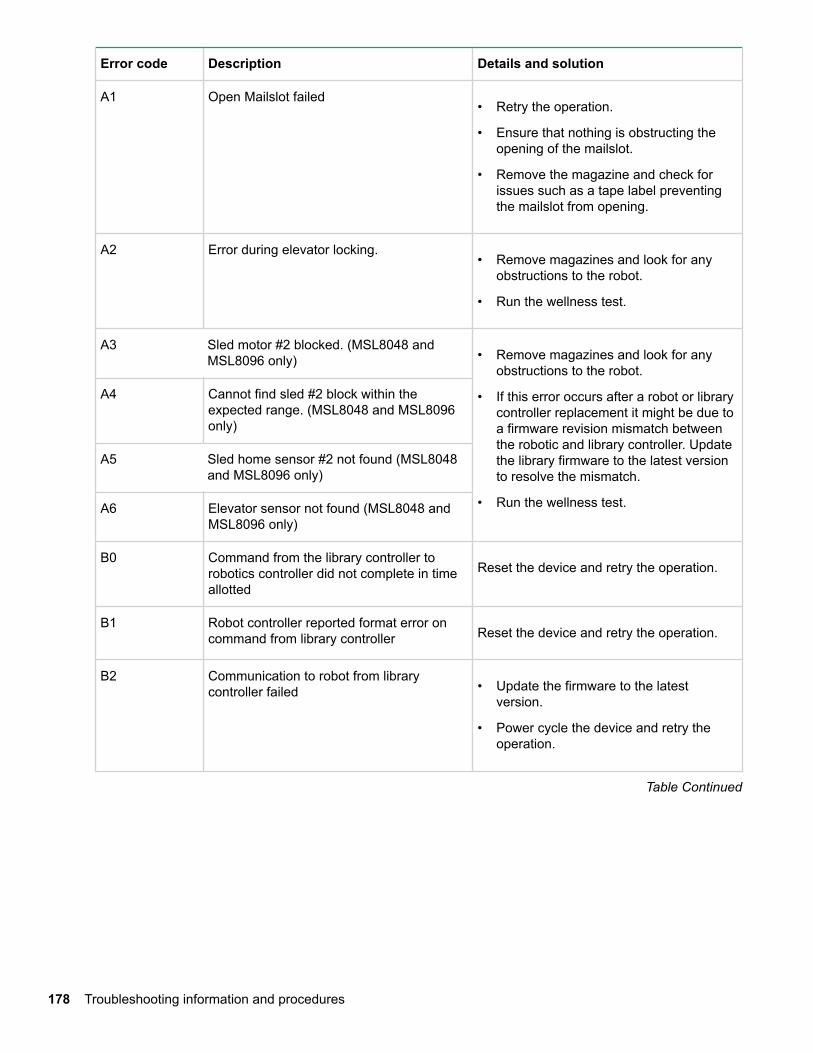
Error code Description Details and solution
A1 Open Mailslot failed• Retry the operation.
• Ensure that nothing is obstructing theopening of the mailslot.
• Remove the magazine and check forissues such as a tape label preventingthe mailslot from opening.
A2 Error during elevator locking.• Remove magazines and look for any
obstructions to the robot.
• Run the wellness test.
A3 Sled motor #2 blocked. (MSL8048 andMSL8096 only) • Remove magazines and look for any
obstructions to the robot.
• If this error occurs after a robot or librarycontroller replacement it might be due toa firmware revision mismatch betweenthe robotic and library controller. Updatethe library firmware to the latest versionto resolve the mismatch.
• Run the wellness test.
A4 Cannot find sled #2 block within theexpected range. (MSL8048 and MSL8096only)
A5 Sled home sensor #2 not found (MSL8048and MSL8096 only)
A6 Elevator sensor not found (MSL8048 andMSL8096 only)
B0 Command from the library controller torobotics controller did not complete in timeallotted
Reset the device and retry the operation.
B1 Robot controller reported format error oncommand from library controller Reset the device and retry the operation.
B2 Communication to robot from librarycontroller failed • Update the firmware to the latest
version.
• Power cycle the device and retry theoperation.
Table Continued
178 Troubleshooting information and procedures
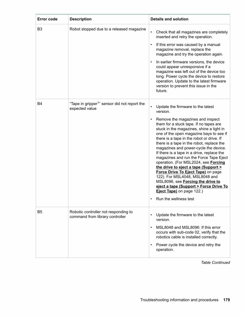
Error code Description Details and solution
B3 Robot stopped due to a released magazine• Check that all magazines are completely
inserted and retry the operation.
• If this error was caused by a manualmagazine removal, replace themagazine and try the operation again.
• In earlier firmware versions, the devicecould appear unresponsive if amagazine was left out of the device toolong. Power cycle the device to restoreoperation. Update to the latest firmwareversion to prevent this issue in thefuture.
B4 “Tape in gripper1” sensor did not report theexpected value • Update the firmware to the latest
version.
• Remove the magazines and inspectthem for a stuck tape. If no tapes arestuck in the magazines, shine a light inone of the open magazine bays to see ifthere is a tape in the robot or drive. Ifthere is a tape in the robot, replace themagazines and power-cycle the device.If there is a tape in a drive, replace themagazines and run the Force Tape Ejectoperation. (For MSL2024, see Forcingthe drive to eject a tape (Support >Force Drive To Eject Tape) on page122). For MSL4048, MSL8048 andMSL8096, see Forcing the drive toeject a tape (Support > Force Drive ToEject Tape) on page 122.)
• Run the wellness test
B5 Robotic controller not responding tocommand from library controller • Update the firmware to the latest
version.
• MSL8048 and MSL8096: If this erroroccurs with sub-code 02, verify that therobotics cable is installed correctly.
• Power cycle the device and retry theoperation.
Table Continued
Troubleshooting information and procedures 179
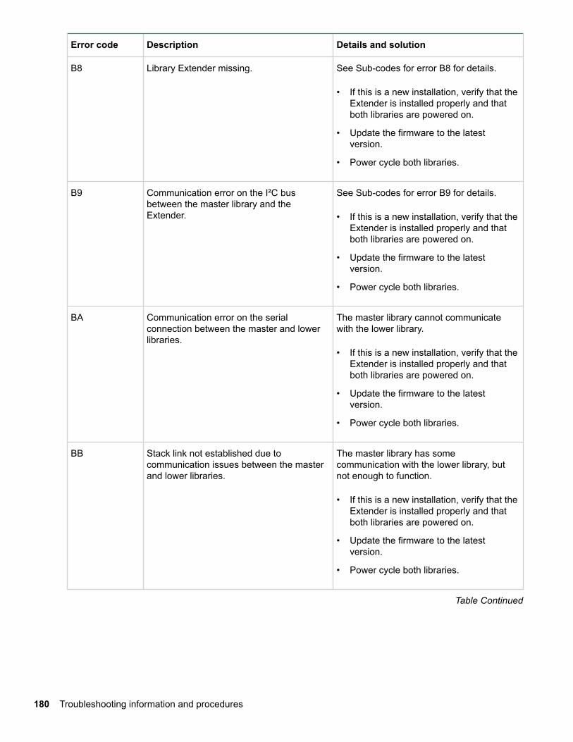
Error code Description Details and solution
B8 Library Extender missing. See Sub-codes for error B8 for details.
• If this is a new installation, verify that theExtender is installed properly and thatboth libraries are powered on.
• Update the firmware to the latestversion.
• Power cycle both libraries.
B9 Communication error on the I²C busbetween the master library and theExtender.
See Sub-codes for error B9 for details.
• If this is a new installation, verify that theExtender is installed properly and thatboth libraries are powered on.
• Update the firmware to the latestversion.
• Power cycle both libraries.
BA Communication error on the serialconnection between the master and lowerlibraries.
The master library cannot communicatewith the lower library.
• If this is a new installation, verify that theExtender is installed properly and thatboth libraries are powered on.
• Update the firmware to the latestversion.
• Power cycle both libraries.
BB Stack link not established due tocommunication issues between the masterand lower libraries.
The master library has somecommunication with the lower library, butnot enough to function.
• If this is a new installation, verify that theExtender is installed properly and thatboth libraries are powered on.
• Update the firmware to the latestversion.
• Power cycle both libraries.
Table Continued
180 Troubleshooting information and procedures
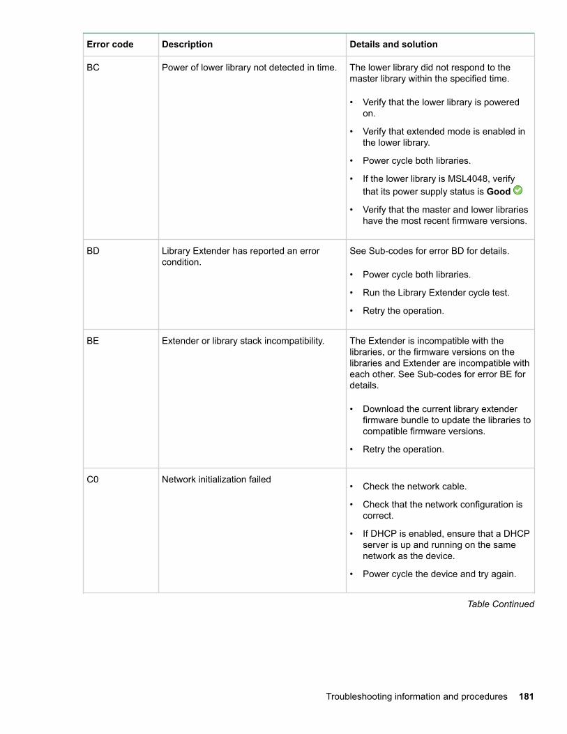
Error code Description Details and solution
BC Power of lower library not detected in time. The lower library did not respond to themaster library within the specified time.
• Verify that the lower library is poweredon.
• Verify that extended mode is enabled inthe lower library.
• Power cycle both libraries.
• If the lower library is MSL4048, verifythat its power supply status is Good
• Verify that the master and lower librarieshave the most recent firmware versions.
BD Library Extender has reported an errorcondition.
See Sub-codes for error BD for details.
• Power cycle both libraries.
• Run the Library Extender cycle test.
• Retry the operation.
BE Extender or library stack incompatibility. The Extender is incompatible with thelibraries, or the firmware versions on thelibraries and Extender are incompatible witheach other. See Sub-codes for error BE fordetails.
• Download the current library extenderfirmware bundle to update the libraries tocompatible firmware versions.
• Retry the operation.
C0 Network initialization failed• Check the network cable.
• Check that the network configuration iscorrect.
• If DHCP is enabled, ensure that a DHCPserver is up and running on the samenetwork as the device.
• Power cycle the device and try again.
Table Continued
Troubleshooting information and procedures 181
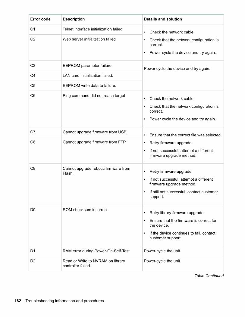
Error code Description Details and solution
C1 Telnet interface initialization failed• Check the network cable.
• Check that the network configuration iscorrect.
• Power cycle the device and try again.
C2 Web server initialization failed
C3 EEPROM parameter failurePower cycle the device and try again.
C4 LAN card initialization failed.
C5 EEPROM write data to failure.
C6 Ping command did not reach target• Check the network cable.
• Check that the network configuration iscorrect.
• Power cycle the device and try again.
C7 Cannot upgrade firmware from USB• Ensure that the correct file was selected.
• Retry firmware upgrade.
• If not successful, attempt a differentfirmware upgrade method.
C8 Cannot upgrade firmware from FTP
C9 Cannot upgrade robotic firmware fromFlash. • Retry firmware upgrade.
• If not successful, attempt a differentfirmware upgrade method.
• If still not successful, contact customersupport.
D0 ROM checksum incorrect• Retry library firmware upgrade.
• Ensure that the firmware is correct forthe device.
• If the device continues to fail, contactcustomer support.
D1 RAM error during Power-On-Self-Test Power-cycle the unit.
D2 Read or Write to NVRAM on librarycontroller failed
Power-cycle the unit.
Table Continued
182 Troubleshooting information and procedures
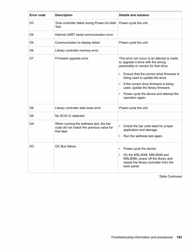
Error code Description Details and solution
D3 Time controller failed during Power-On-Self-Test
Power-cycle the unit.
D4 Internal UART serial communication error
D5 Communication to display failed Power-cycle the unit.
D6 Library controller memory error
D7 Firmware upgrade error This error can occur is an attempt is madeto upgrade a drive with the wrongpersonality or version for that drive.
• Ensure that the correct drive firmware isbeing used to update the drive.
• If the correct drive firmware is beingused, update the library firmware.
• Power cycle the device and attempt theoperation again.
D8 Library controller data base error Power-cycle the unit.
D9 No SCSI IC detected
DA When running the wellness test, the barcode did not match the previous value forthat tape
• Check the bar code label for properapplication and damage.
• Run the wellness test again.
DC I2C Bus failure.• Power-cycle the device.
• On the MSL4048, MSL8048 andMSL8096, power off the library andreseat the library controller from theback panel.
Table Continued
Troubleshooting information and procedures 183
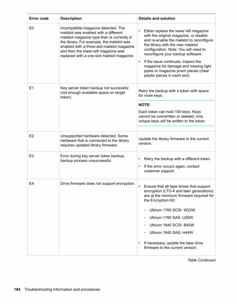
Error code Description Details and solution
E0 Incompatible magazine detected. Themailslot was enabled with a differentmailslot magazine type than is currently inthe library. For example, the mailslot wasenabled with a three-slot mailslot magazineand then the lower-left magazine wasreplaced with a one-slot mailslot magazine.
• Either replace the lower left magazinewith the original magazine, or disableand re-enable the mailslot to reconfigurethe library with the new mailslotconfiguration. Note: You will need toreconfigure your backup software.
• If the issue continues, inspect themagazine for damage and missing lightpipes or magazine prism pieces (clearplastic pieces in each slot).
E1 Key server token backup not successful(not enough available space on targettoken)
Retry the backup with a token with spacefor more keys.
NOTE:
Each token can hold 100 keys. Keyscannot be overwritten or deleted; onlyunique keys will be written to the token.
E2 Unsupported hardware detected. Somehardware that is connected to the libraryrequires updated library firmware.
Update the library firmware to the currentversion.
E3 Error during key server token backup;backup process unsuccessful. • Retry the backup with a different token.
• If the error occurs again, contactcustomer support.
E4 Drive firmware does not support encryption.• Ensure that all tape drives that support
encryption (LTO-4 and later generations)are at the minimum firmware required forthe Encryption Kit:
◦ Ultrium 1760 SCSI: W22W
◦ Ultrium 1760 SAS: U26W
◦ Ultrium 1840 SCSI: B45W
◦ Ultrium 1840 SAS: H44W
• If necessary, update the tape drivefirmware to the current version.
Table Continued
184 Troubleshooting information and procedures
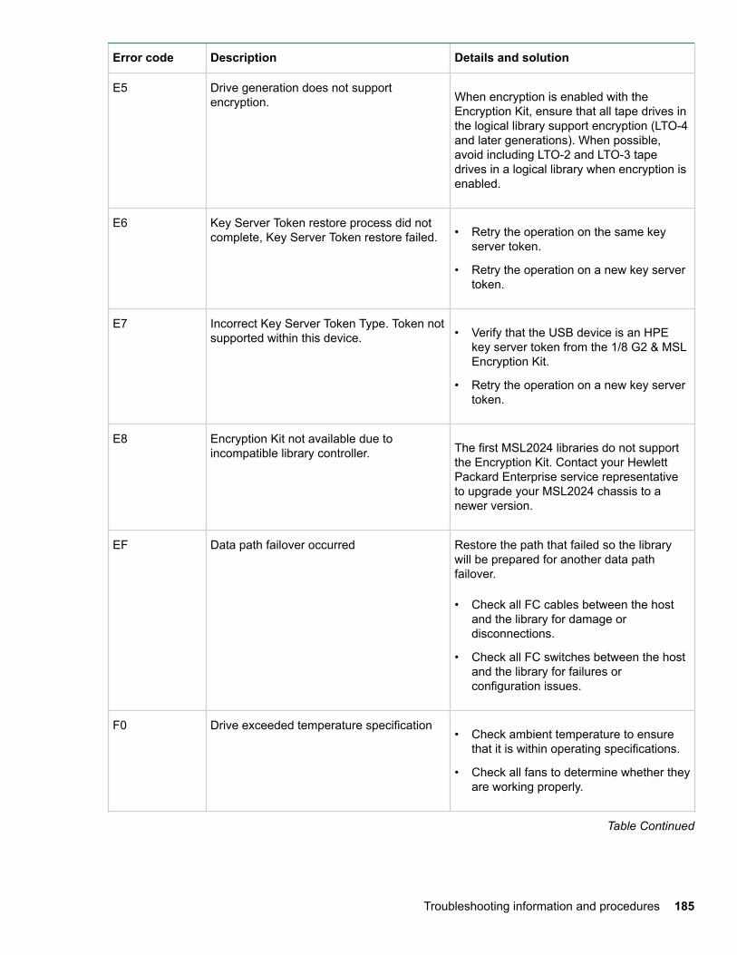
Error code Description Details and solution
E5 Drive generation does not supportencryption. When encryption is enabled with the
Encryption Kit, ensure that all tape drives inthe logical library support encryption (LTO-4and later generations). When possible,avoid including LTO-2 and LTO-3 tapedrives in a logical library when encryption isenabled.
E6 Key Server Token restore process did notcomplete, Key Server Token restore failed. • Retry the operation on the same key
server token.
• Retry the operation on a new key servertoken.
E7 Incorrect Key Server Token Type. Token notsupported within this device. • Verify that the USB device is an HPE
key server token from the 1/8 G2 & MSLEncryption Kit.
• Retry the operation on a new key servertoken.
E8 Encryption Kit not available due toincompatible library controller. The first MSL2024 libraries do not support
the Encryption Kit. Contact your HewlettPackard Enterprise service representativeto upgrade your MSL2024 chassis to anewer version.
EF Data path failover occurred Restore the path that failed so the librarywill be prepared for another data pathfailover.
• Check all FC cables between the hostand the library for damage ordisconnections.
• Check all FC switches between the hostand the library for failures orconfiguration issues.
F0 Drive exceeded temperature specification• Check ambient temperature to ensure
that it is within operating specifications.
• Check all fans to determine whether theyare working properly.
Table Continued
Troubleshooting information and procedures 185
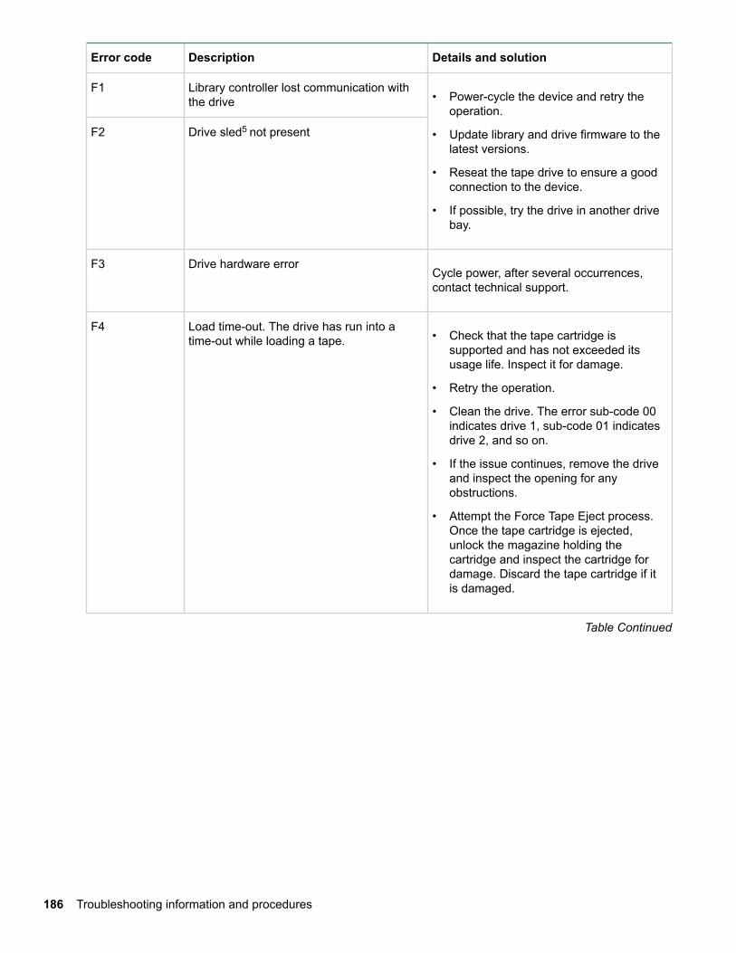
Error code Description Details and solution
F1 Library controller lost communication withthe drive • Power-cycle the device and retry the
operation.
• Update library and drive firmware to thelatest versions.
• Reseat the tape drive to ensure a goodconnection to the device.
• If possible, try the drive in another drivebay.
F2 Drive sled5 not present
F3 Drive hardware errorCycle power, after several occurrences,contact technical support.
F4 Load time-out. The drive has run into atime-out while loading a tape. • Check that the tape cartridge is
supported and has not exceeded itsusage life. Inspect it for damage.
• Retry the operation.
• Clean the drive. The error sub-code 00indicates drive 1, sub-code 01 indicatesdrive 2, and so on.
• If the issue continues, remove the driveand inspect the opening for anyobstructions.
• Attempt the Force Tape Eject process.Once the tape cartridge is ejected,unlock the magazine holding thecartridge and inspect the cartridge fordamage. Discard the tape cartridge if itis damaged.
Table Continued
186 Troubleshooting information and procedures
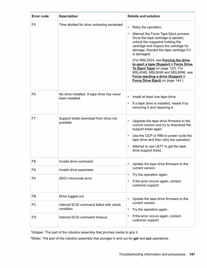
Error code Description Details and solution
F5 Time allotted for drive unloading exceeded• Retry the operation.
• Attempt the Force Tape Eject process.Once the tape cartridge is ejected,unlock the magazine holding thecartridge and inspect the cartridge fordamage. Discard the tape cartridge if itis damaged.
(For MSL2024, see Forcing the driveto eject a tape (Support > Force DriveTo Eject Tape) on page 122). ForMSL4048, MSL8048 and MSL8096, see Force ejecting a drive (Support >Force Drive Eject) on page 144.)
F6 No drive installed. A tape drive has neverbeen installed. • Install at least one tape drive.
• If a tape drive is installed, reseat it byremoving it and replacing it.
F7 Support ticket download from drive notpossible. • Upgrade the tape drive firmware to the
current version and try to download thesupport ticket again.
• Use the OCP or RMI to power cycle thetape drive and then retry the operation.
• Attempt to use L&TT to get the tapedrive support ticket.
F8 Invalid drive command• Update the tape drive firmware to the
current version.
• Try the operation again.
• If the error occurs again, contactcustomer support.
F9 Invalid drive parameter
FA SDCI microcode error
FB Drive logged out• Update the tape drive firmware to the
current version.
• Try the operation again.
• If the error occurs again, contactcustomer support.
FC Internal SCSI command failed with checkcondition
FD Internal SCSI command timeout
1Gripper: The part of the robotics assembly that pinches media to grip it.2Slider: The part of the robotics assembly that plunges in and out for get and put operations.
Troubleshooting information and procedures 187
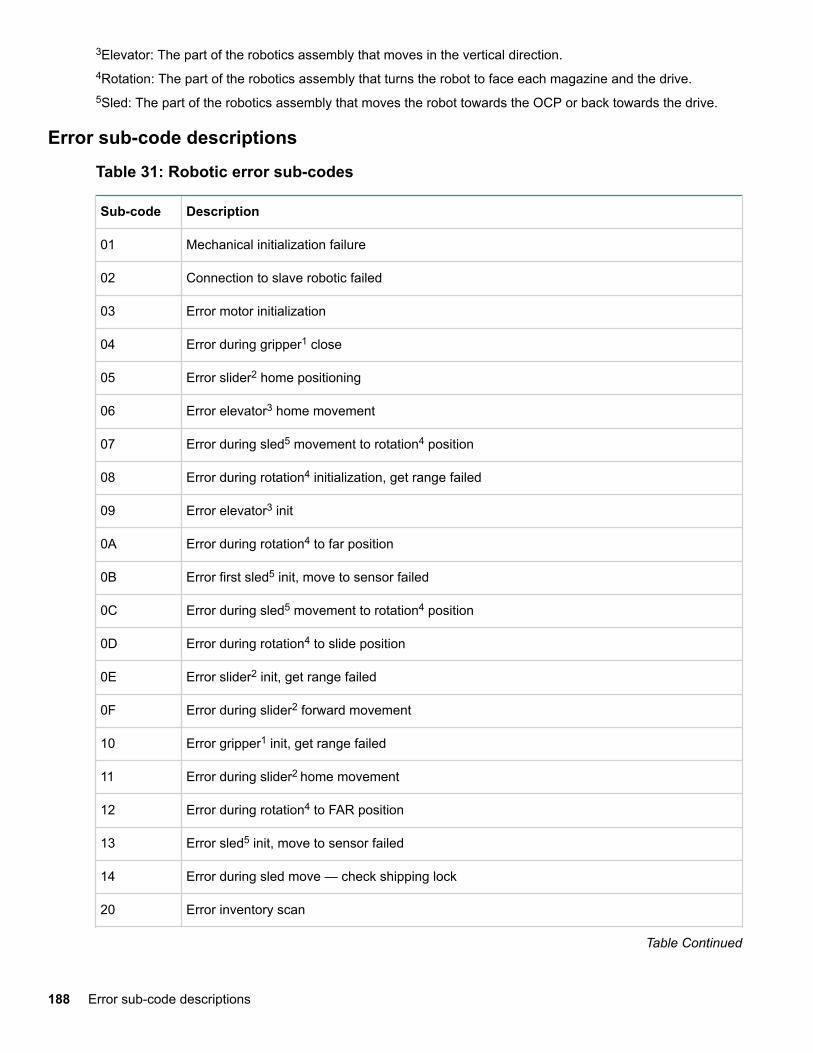
3Elevator: The part of the robotics assembly that moves in the vertical direction.4Rotation: The part of the robotics assembly that turns the robot to face each magazine and the drive.5Sled: The part of the robotics assembly that moves the robot towards the OCP or back towards the drive.
Error sub-code descriptionsTable 31: Robotic error sub-codes
Sub-code Description
01 Mechanical initialization failure
02 Connection to slave robotic failed
03 Error motor initialization
04 Error during gripper1 close
05 Error slider2 home positioning
06 Error elevator3 home movement
07 Error during sled5 movement to rotation4 position
08 Error during rotation4 initialization, get range failed
09 Error elevator3 init
0A Error during rotation4 to far position
0B Error first sled5 init, move to sensor failed
0C Error during sled5 movement to rotation4 position
0D Error during rotation4 to slide position
0E Error slider2 init, get range failed
0F Error during slider2 forward movement
10 Error gripper1 init, get range failed
11 Error during slider2 home movement
12 Error during rotation4 to FAR position
13 Error sled5 init, move to sensor failed
14 Error during sled move — check shipping lock
20 Error inventory scan
Table Continued
188 Error sub-code descriptions
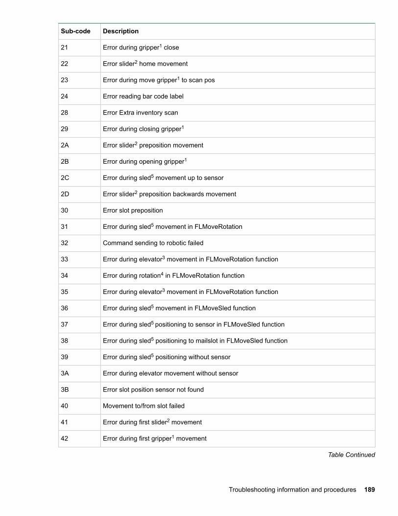
Sub-code Description
21 Error during gripper1 close
22 Error slider2 home movement
23 Error during move gripper1 to scan pos
24 Error reading bar code label
28 Error Extra inventory scan
29 Error during closing gripper1
2A Error slider2 preposition movement
2B Error during opening gripper1
2C Error during sled5 movement up to sensor
2D Error slider2 preposition backwards movement
30 Error slot preposition
31 Error during sled5 movement in FLMoveRotation
32 Command sending to robotic failed
33 Error during elevator3 movement in FLMoveRotation function
34 Error during rotation4 in FLMoveRotation function
35 Error during elevator3 movement in FLMoveRotation function
36 Error during sled5 movement in FLMoveSled function
37 Error during sled5 positioning to sensor in FLMoveSled function
38 Error during sled5 positioning to mailslot in FLMoveSled function
39 Error during sled5 positioning without sensor
3A Error during elevator movement without sensor
3B Error slot position sensor not found
40 Movement to/from slot failed
41 Error during first slider2 movement
42 Error during first gripper1 movement
Table Continued
Troubleshooting information and procedures 189
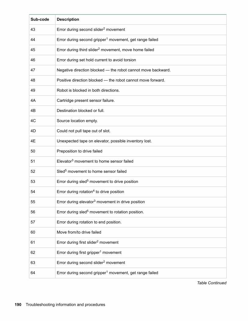
Sub-code Description
43 Error during second slider2 movement
44 Error during second gripper1 movement, get range failed
45 Error during third slider2 movement, move home failed
46 Error during set hold current to avoid torsion
47 Negative direction blocked — the robot cannot move backward.
48 Positive direction blocked — the robot cannot move forward.
49 Robot is blocked in both directions.
4A Cartridge present sensor failure.
4B Destination blocked or full.
4C Source location empty.
4D Could not pull tape out of slot.
4E Unexpected tape on elevator, possible inventory lost.
50 Preposition to drive failed
51 Elevator3 movement to home sensor failed
52 Sled5 movement to home sensor failed
53 Error during sled5 movement to drive position
54 Error during rotation4 to drive position
55 Error during elevator3 movement in drive position
56 Error during sled5 movement to rotation position.
57 Error during rotation to end position.
60 Move from/to drive failed
61 Error during first slider2 movement
62 Error during first gripper1 movement
63 Error during second slider2 movement
64 Error during second gripper1 movement, get range failed
Table Continued
190 Troubleshooting information and procedures
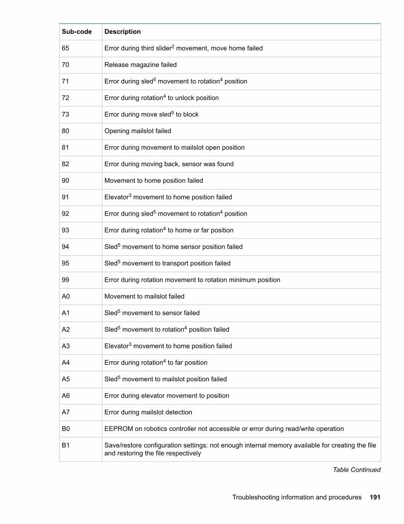
Sub-code Description
65 Error during third slider2 movement, move home failed
70 Release magazine failed
71 Error during sled5 movement to rotation4 position
72 Error during rotation4 to unlock position
73 Error during move sled5 to block
80 Opening mailslot failed
81 Error during movement to mailslot open position
82 Error during moving back, sensor was found
90 Movement to home position failed
91 Elevator3 movement to home position failed
92 Error during sled5 movement to rotation4 position
93 Error during rotation4 to home or far position
94 Sled5 movement to home sensor position failed
95 Sled5 movement to transport position failed
99 Error during rotation movement to rotation minimum position
A0 Movement to mailslot failed
A1 Sled5 movement to sensor failed
A2 Sled5 movement to rotation4 position failed
A3 Elevator3 movement to home position failed
A4 Error during rotation4 to far position
A5 Sled5 movement to mailslot position failed
A6 Error during elevator movement to position
A7 Error during mailslot detection
B0 EEPROM on robotics controller not accessible or error during read/write operation
B1 Save/restore configuration settings: not enough internal memory available for creating the fileand restoring the file respectively
Table Continued
Troubleshooting information and procedures 191
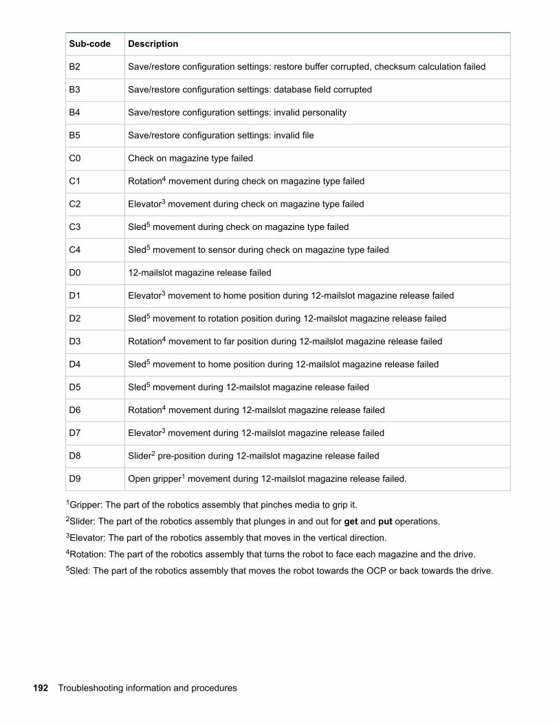
Sub-code Description
B2 Save/restore configuration settings: restore buffer corrupted, checksum calculation failed
B3 Save/restore configuration settings: database field corrupted
B4 Save/restore configuration settings: invalid personality
B5 Save/restore configuration settings: invalid file
C0 Check on magazine type failed
C1 Rotation4 movement during check on magazine type failed
C2 Elevator3 movement during check on magazine type failed
C3 Sled5 movement during check on magazine type failed
C4 Sled5 movement to sensor during check on magazine type failed
D0 12-mailslot magazine release failed
D1 Elevator3 movement to home position during 12-mailslot magazine release failed
D2 Sled5 movement to rotation position during 12-mailslot magazine release failed
D3 Rotation4 movement to far position during 12-mailslot magazine release failed
D4 Sled5 movement to home position during 12-mailslot magazine release failed
D5 Sled5 movement during 12-mailslot magazine release failed
D6 Rotation4 movement during 12-mailslot magazine release failed
D7 Elevator3 movement during 12-mailslot magazine release failed
D8 Slider2 pre-position during 12-mailslot magazine release failed
D9 Open gripper1 movement during 12-mailslot magazine release failed.
1Gripper: The part of the robotics assembly that pinches media to grip it.2Slider: The part of the robotics assembly that plunges in and out for get and put operations.3Elevator: The part of the robotics assembly that moves in the vertical direction.4Rotation: The part of the robotics assembly that turns the robot to face each magazine and the drive.5Sled: The part of the robotics assembly that moves the robot towards the OCP or back towards the drive.
192 Troubleshooting information and procedures
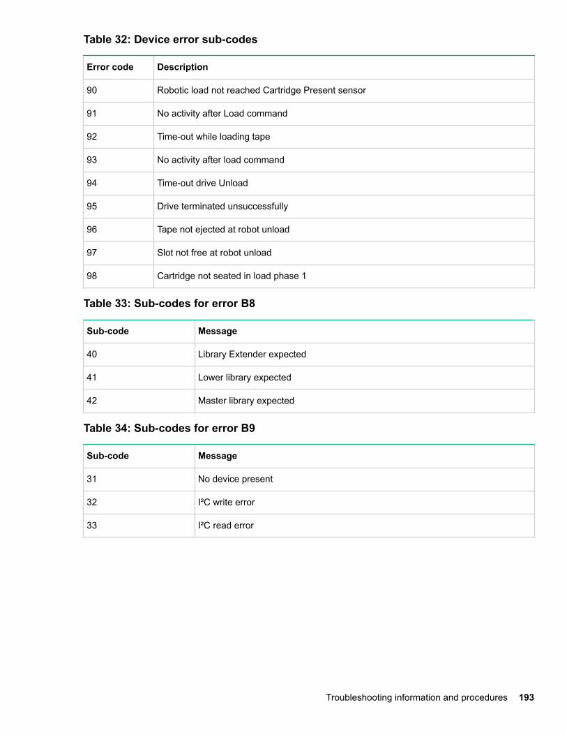
Table 32: Device error sub-codes
Error code Description
90 Robotic load not reached Cartridge Present sensor
91 No activity after Load command
92 Time-out while loading tape
93 No activity after load command
94 Time-out drive Unload
95 Drive terminated unsuccessfully
96 Tape not ejected at robot unload
97 Slot not free at robot unload
98 Cartridge not seated in load phase 1
Table 33: Sub-codes for error B8
Sub-code Message
40 Library Extender expected
41 Lower library expected
42 Master library expected
Table 34: Sub-codes for error B9
Sub-code Message
31 No device present
32 I²C write error
33 I²C read error
Troubleshooting information and procedures 193
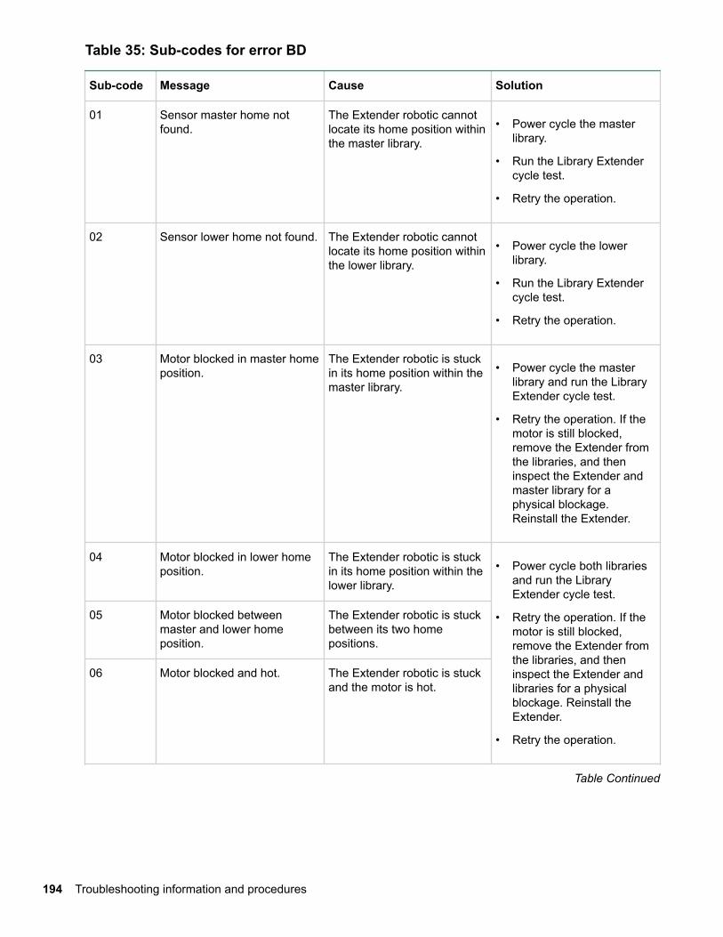
Table 35: Sub-codes for error BD
Sub-code Message Cause Solution
01 Sensor master home notfound.
The Extender robotic cannotlocate its home position withinthe master library.
• Power cycle the masterlibrary.
• Run the Library Extendercycle test.
• Retry the operation.
02 Sensor lower home not found. The Extender robotic cannotlocate its home position withinthe lower library.
• Power cycle the lowerlibrary.
• Run the Library Extendercycle test.
• Retry the operation.
03 Motor blocked in master homeposition.
The Extender robotic is stuckin its home position within themaster library.
• Power cycle the masterlibrary and run the LibraryExtender cycle test.
• Retry the operation. If themotor is still blocked,remove the Extender fromthe libraries, and theninspect the Extender andmaster library for aphysical blockage.Reinstall the Extender.
04 Motor blocked in lower homeposition.
The Extender robotic is stuckin its home position within thelower library.
• Power cycle both librariesand run the LibraryExtender cycle test.
• Retry the operation. If themotor is still blocked,remove the Extender fromthe libraries, and theninspect the Extender andlibraries for a physicalblockage. Reinstall theExtender.
• Retry the operation.
05 Motor blocked betweenmaster and lower homeposition.
The Extender robotic is stuckbetween its two homepositions.
06 Motor blocked and hot. The Extender robotic is stuckand the motor is hot.
Table Continued
194 Troubleshooting information and procedures
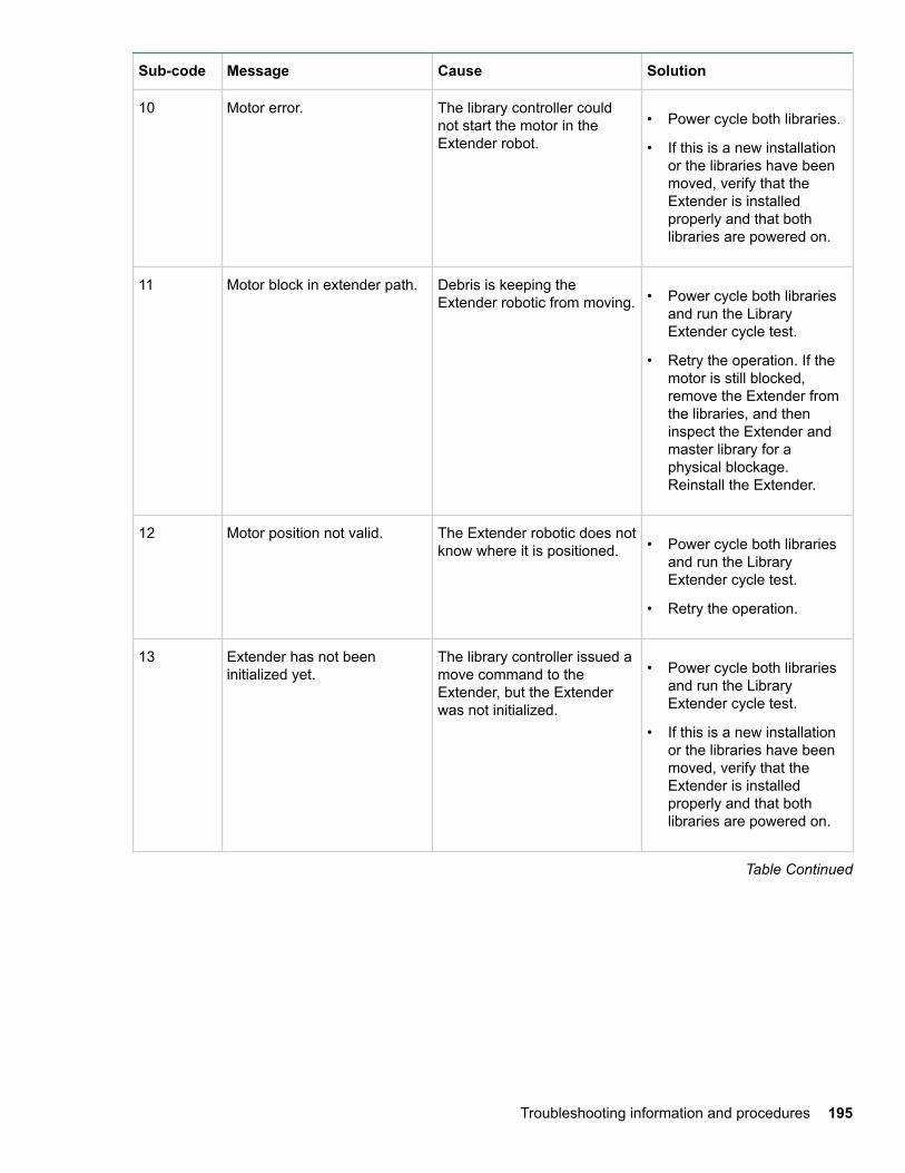
Sub-code Message Cause Solution
10 Motor error. The library controller couldnot start the motor in theExtender robot.
• Power cycle both libraries.
• If this is a new installationor the libraries have beenmoved, verify that theExtender is installedproperly and that bothlibraries are powered on.
11 Motor block in extender path. Debris is keeping theExtender robotic from moving. • Power cycle both libraries
and run the LibraryExtender cycle test.
• Retry the operation. If themotor is still blocked,remove the Extender fromthe libraries, and theninspect the Extender andmaster library for aphysical blockage.Reinstall the Extender.
12 Motor position not valid. The Extender robotic does notknow where it is positioned. • Power cycle both libraries
and run the LibraryExtender cycle test.
• Retry the operation.
13 Extender has not beeninitialized yet.
The library controller issued amove command to theExtender, but the Extenderwas not initialized.
• Power cycle both librariesand run the LibraryExtender cycle test.
• If this is a new installationor the libraries have beenmoved, verify that theExtender is installedproperly and that bothlibraries are powered on.
Table Continued
Troubleshooting information and procedures 195
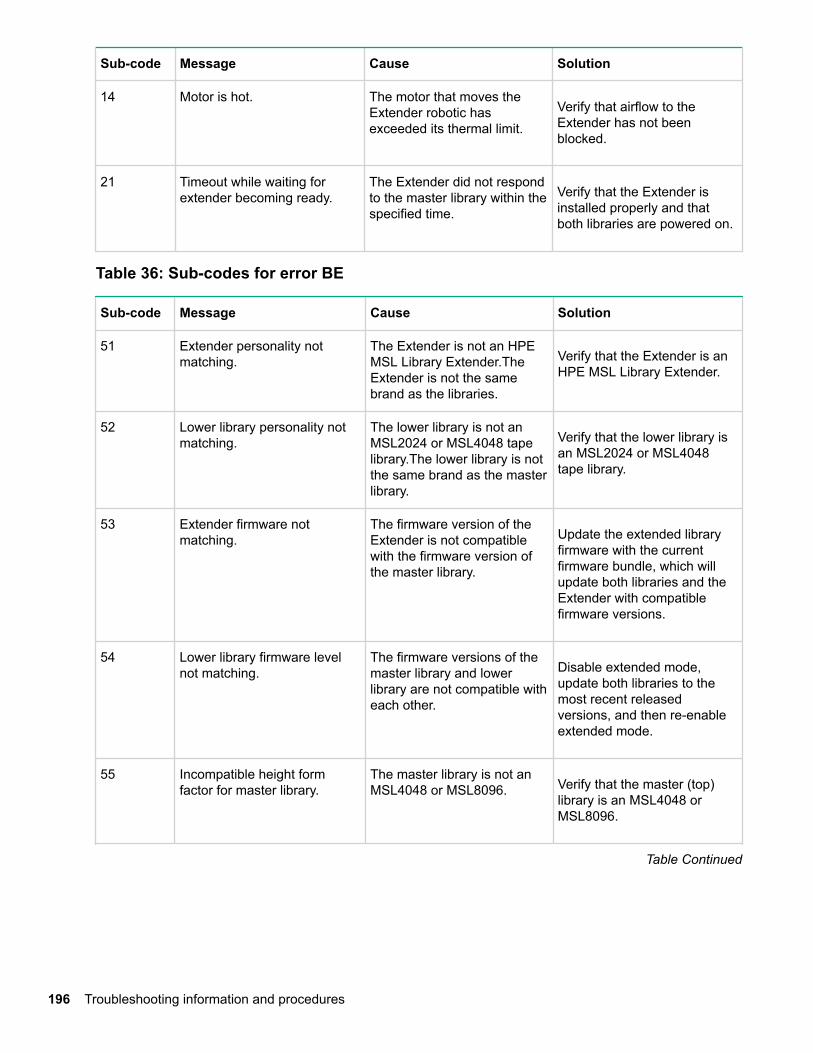
Sub-code Message Cause Solution
14 Motor is hot. The motor that moves theExtender robotic hasexceeded its thermal limit.
Verify that airflow to theExtender has not beenblocked.
21 Timeout while waiting forextender becoming ready.
The Extender did not respondto the master library within thespecified time.
Verify that the Extender isinstalled properly and thatboth libraries are powered on.
Table 36: Sub-codes for error BE
Sub-code Message Cause Solution
51 Extender personality notmatching.
The Extender is not an HPEMSL Library Extender.TheExtender is not the samebrand as the libraries.
Verify that the Extender is anHPE MSL Library Extender.
52 Lower library personality notmatching.
The lower library is not anMSL2024 or MSL4048 tapelibrary.The lower library is notthe same brand as the masterlibrary.
Verify that the lower library isan MSL2024 or MSL4048tape library.
53 Extender firmware notmatching.
The firmware version of theExtender is not compatiblewith the firmware version ofthe master library.
Update the extended libraryfirmware with the currentfirmware bundle, which willupdate both libraries and theExtender with compatiblefirmware versions.
54 Lower library firmware levelnot matching.
The firmware versions of themaster library and lowerlibrary are not compatible witheach other.
Disable extended mode,update both libraries to themost recent releasedversions, and then re-enableextended mode.
55 Incompatible height formfactor for master library.
The master library is not anMSL4048 or MSL8096. Verify that the master (top)
library is an MSL4048 orMSL8096.
Table Continued
196 Troubleshooting information and procedures
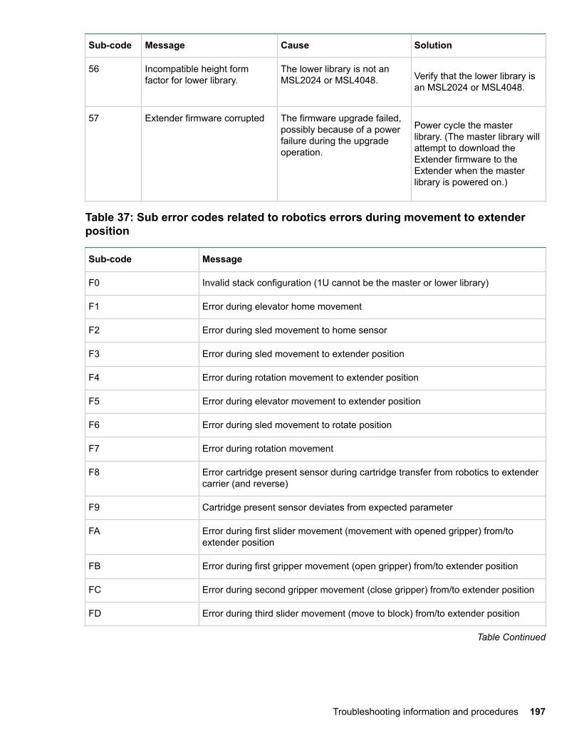
Sub-code Message Cause Solution
56 Incompatible height formfactor for lower library.
The lower library is not anMSL2024 or MSL4048. Verify that the lower library is
an MSL2024 or MSL4048.
57 Extender firmware corrupted The firmware upgrade failed,possibly because of a powerfailure during the upgradeoperation.
Power cycle the masterlibrary. (The master library willattempt to download theExtender firmware to theExtender when the masterlibrary is powered on.)
Table 37: Sub error codes related to robotics errors during movement to extenderposition
Sub-code Message
F0 Invalid stack configuration (1U cannot be the master or lower library)
F1 Error during elevator home movement
F2 Error during sled movement to home sensor
F3 Error during sled movement to extender position
F4 Error during rotation movement to extender position
F5 Error during elevator movement to extender position
F6 Error during sled movement to rotate position
F7 Error during rotation movement
F8 Error cartridge present sensor during cartridge transfer from robotics to extendercarrier (and reverse)
F9 Cartridge present sensor deviates from expected parameter
FA Error during first slider movement (movement with opened gripper) from/toextender position
FB Error during first gripper movement (open gripper) from/to extender position
FC Error during second gripper movement (close gripper) from/to extender position
FD Error during third slider movement (move to block) from/to extender position
Table Continued
Troubleshooting information and procedures 197
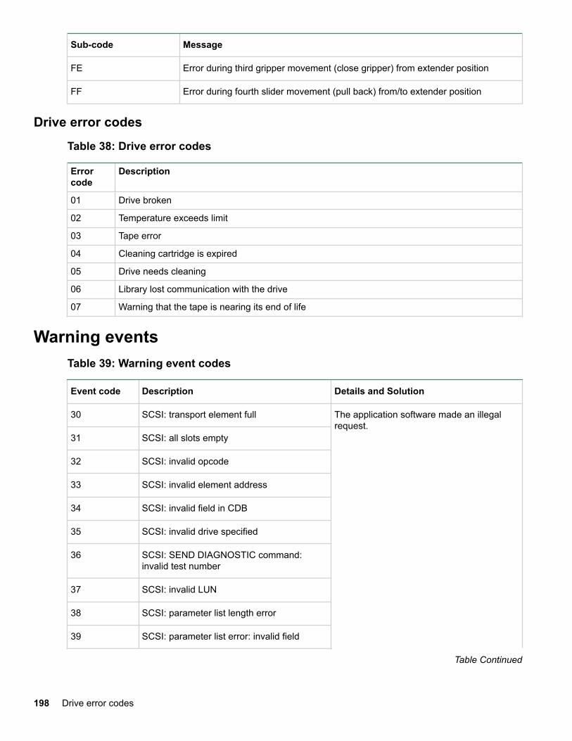
Sub-code Message
FE Error during third gripper movement (close gripper) from extender position
FF Error during fourth slider movement (pull back) from/to extender position
Drive error codesTable 38: Drive error codes
Errorcode
Description
01 Drive broken
02 Temperature exceeds limit
03 Tape error
04 Cleaning cartridge is expired
05 Drive needs cleaning
06 Library lost communication with the drive
07 Warning that the tape is nearing its end of life
Warning eventsTable 39: Warning event codes
Event code Description Details and Solution
30 SCSI: transport element full The application software made an illegalrequest.
31 SCSI: all slots empty
32 SCSI: invalid opcode
33 SCSI: invalid element address
34 SCSI: invalid field in CDB
35 SCSI: invalid drive specified
36 SCSI: SEND DIAGNOSTIC command:invalid test number
37 SCSI: invalid LUN
38 SCSI: parameter list length error
39 SCSI: parameter list error: invalid field
Table Continued
198 Drive error codes
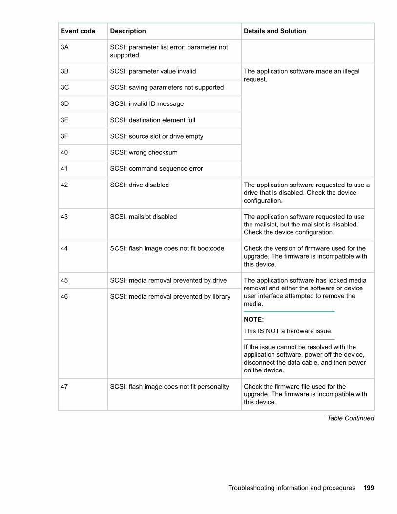
Event code Description Details and Solution
3A SCSI: parameter list error: parameter notsupported
3B SCSI: parameter value invalid The application software made an illegalrequest.
3C SCSI: saving parameters not supported
3D SCSI: invalid ID message
3E SCSI: destination element full
3F SCSI: source slot or drive empty
40 SCSI: wrong checksum
41 SCSI: command sequence error
42 SCSI: drive disabled The application software requested to use adrive that is disabled. Check the deviceconfiguration.
43 SCSI: mailslot disabled The application software requested to usethe mailslot, but the mailslot is disabled.Check the device configuration.
44 SCSI: flash image does not fit bootcode Check the version of firmware used for theupgrade. The firmware is incompatible withthis device.
45 SCSI: media removal prevented by drive The application software has locked mediaremoval and either the software or deviceuser interface attempted to remove themedia.
NOTE:
This IS NOT a hardware issue.
If the issue cannot be resolved with theapplication software, power off the device,disconnect the data cable, and then poweron the device.
46 SCSI: media removal prevented by library
47 SCSI: flash image does not fit personality Check the firmware file used for theupgrade. The firmware is incompatible withthis device.
Table Continued
Troubleshooting information and procedures 199
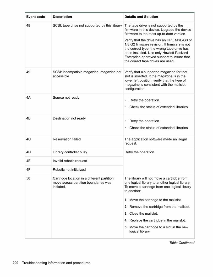
Event code Description Details and Solution
48 SCSI: tape drive not supported by this library The tape drive is not supported by thefirmware in this device. Upgrade the devicefirmware to the most up-to-date version.
Verify that the drive has an HPE MSL-G3 or1/8 G2 firmware revision. If firmware is notthe correct type, the wrong tape drive hasbeen installed. Use only Hewlett PackardEnterprise-approved support to insure thatthe correct tape drives are used.
49 SCSI: incompatible magazine, magazine notaccessible
Verify that a supported magazine for thatslot is inserted. If the magazine is in thelower left position, verify that the type ofmagazine is consistent with the mailslotconfiguration.
4A Source not ready• Retry the operation.
• Check the status of extended libraries.
4B Destination not ready• Retry the operation.
• Check the status of extended libraries.
4C Reservation failed The application software made an illegalrequest.
4D Library controller busy Retry the operation.
4E Invalid robotic request
4F Robotic not initialized
50 Cartridge location in a different partition;move across partition boundaries wasinitiated.
The library will not move a cartridge fromone logical library to another logical library.To move a cartridge from one logical libraryto another:
1. Move the cartridge to the mailslot.
2. Remove the cartridge from the mailslot.
3. Close the mailslot.
4. Replace the cartridge in the mailslot.
5. Move the cartridge to a slot in the newlogical library.
Table Continued
200 Troubleshooting information and procedures
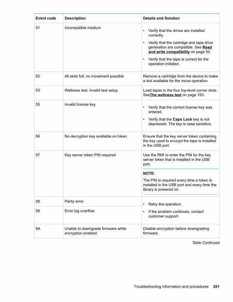
Event code Description Details and Solution
51 Incompatible medium• Verify that the drives are installed
correctly.
• Verify that the cartridge and tape drivegeneration are compatible. See Readand write compatibility on page 50.
• Verify that the tape is correct for theoperation initiated.
52 All slots full; no movement possible Remove a cartridge from the device to makea slot available for the move operation.
53 Wellness test: invalid test setup Load tapes in the four top-level corner slots.SeeThe wellness test on page 163.
55 Invalid license key• Verify that the correct license key was
entered.
• Verify that the Caps Lock key is notdepressed. The key is case sensitive.
56 No decryption key available on token Ensure that the key server token containingthe key used to encrypt the tape is installedin the USB port.
57 Key server token PIN required Use the RMI to enter the PIN for the keyserver token that is installed in the USBport.
NOTE:
The PIN is required every time a token isinstalled in the USB port and every time thelibrary is powered on.
58 Parity error• Retry the operation.
• If the problem continues, contactcustomer support.
59 Error log overflow
5A Unable to downgrade firmware whileencryption enabled.
Disable encryption before downgradingfirmware.
Table Continued
Troubleshooting information and procedures 201
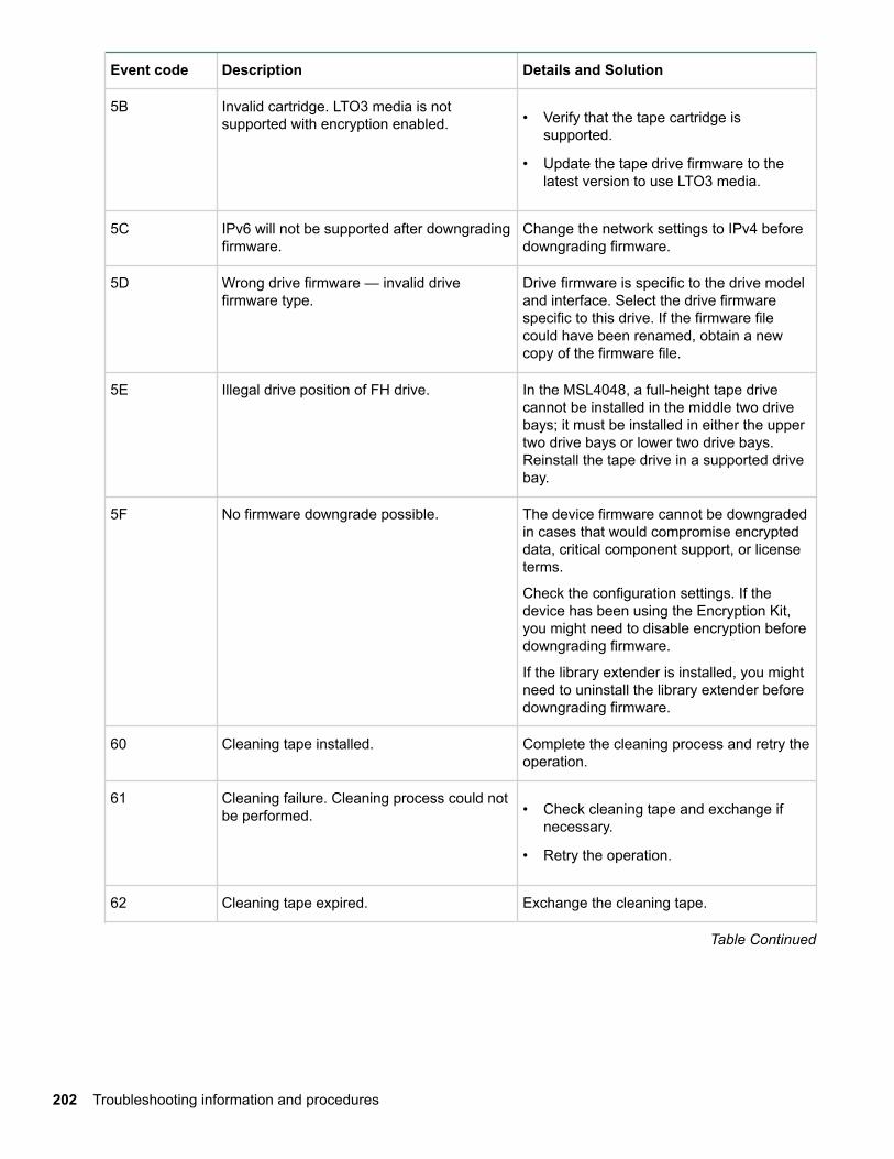
Event code Description Details and Solution
5B Invalid cartridge. LTO3 media is notsupported with encryption enabled. • Verify that the tape cartridge is
supported.
• Update the tape drive firmware to thelatest version to use LTO3 media.
5C IPv6 will not be supported after downgradingfirmware.
Change the network settings to IPv4 beforedowngrading firmware.
5D Wrong drive firmware — invalid drivefirmware type.
Drive firmware is specific to the drive modeland interface. Select the drive firmwarespecific to this drive. If the firmware filecould have been renamed, obtain a newcopy of the firmware file.
5E Illegal drive position of FH drive. In the MSL4048, a full-height tape drivecannot be installed in the middle two drivebays; it must be installed in either the uppertwo drive bays or lower two drive bays.Reinstall the tape drive in a supported drivebay.
5F No firmware downgrade possible. The device firmware cannot be downgradedin cases that would compromise encrypteddata, critical component support, or licenseterms.
Check the configuration settings. If thedevice has been using the Encryption Kit,you might need to disable encryption beforedowngrading firmware.
If the library extender is installed, you mightneed to uninstall the library extender beforedowngrading firmware.
60 Cleaning tape installed. Complete the cleaning process and retry theoperation.
61 Cleaning failure. Cleaning process could notbe performed. • Check cleaning tape and exchange if
necessary.
• Retry the operation.
62 Cleaning tape expired. Exchange the cleaning tape.
Table Continued
202 Troubleshooting information and procedures
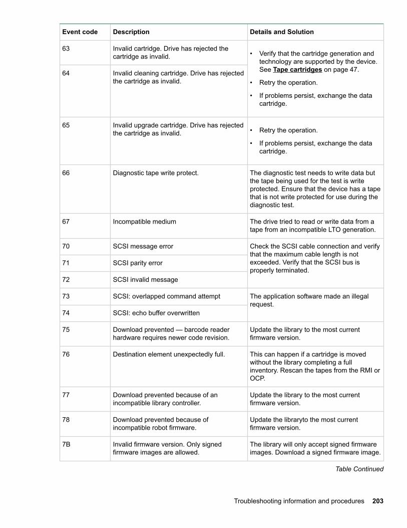
Event code Description Details and Solution
63 Invalid cartridge. Drive has rejected thecartridge as invalid. • Verify that the cartridge generation and
technology are supported by the device.See Tape cartridges on page 47.
• Retry the operation.
• If problems persist, exchange the datacartridge.
64 Invalid cleaning cartridge. Drive has rejectedthe cartridge as invalid.
65 Invalid upgrade cartridge. Drive has rejectedthe cartridge as invalid. • Retry the operation.
• If problems persist, exchange the datacartridge.
66 Diagnostic tape write protect. The diagnostic test needs to write data butthe tape being used for the test is writeprotected. Ensure that the device has a tapethat is not write protected for use during thediagnostic test.
67 Incompatible medium The drive tried to read or write data from atape from an incompatible LTO generation.
70 SCSI message error Check the SCSI cable connection and verifythat the maximum cable length is notexceeded. Verify that the SCSI bus isproperly terminated.
71 SCSI parity error
72 SCSI invalid message
73 SCSI: overlapped command attempt The application software made an illegalrequest.
74 SCSI: echo buffer overwritten
75 Download prevented — barcode readerhardware requires newer code revision.
Update the library to the most currentfirmware version.
76 Destination element unexpectedly full. This can happen if a cartridge is movedwithout the library completing a fullinventory. Rescan the tapes from the RMI orOCP.
77 Download prevented because of anincompatible library controller.
Update the library to the most currentfirmware version.
78 Download prevented because ofincompatible robot firmware.
Update the libraryto the most currentfirmware version.
7B Invalid firmware version. Only signedfirmware images are allowed.
The library will only accept signed firmwareimages. Download a signed firmware image.
Table Continued
Troubleshooting information and procedures 203
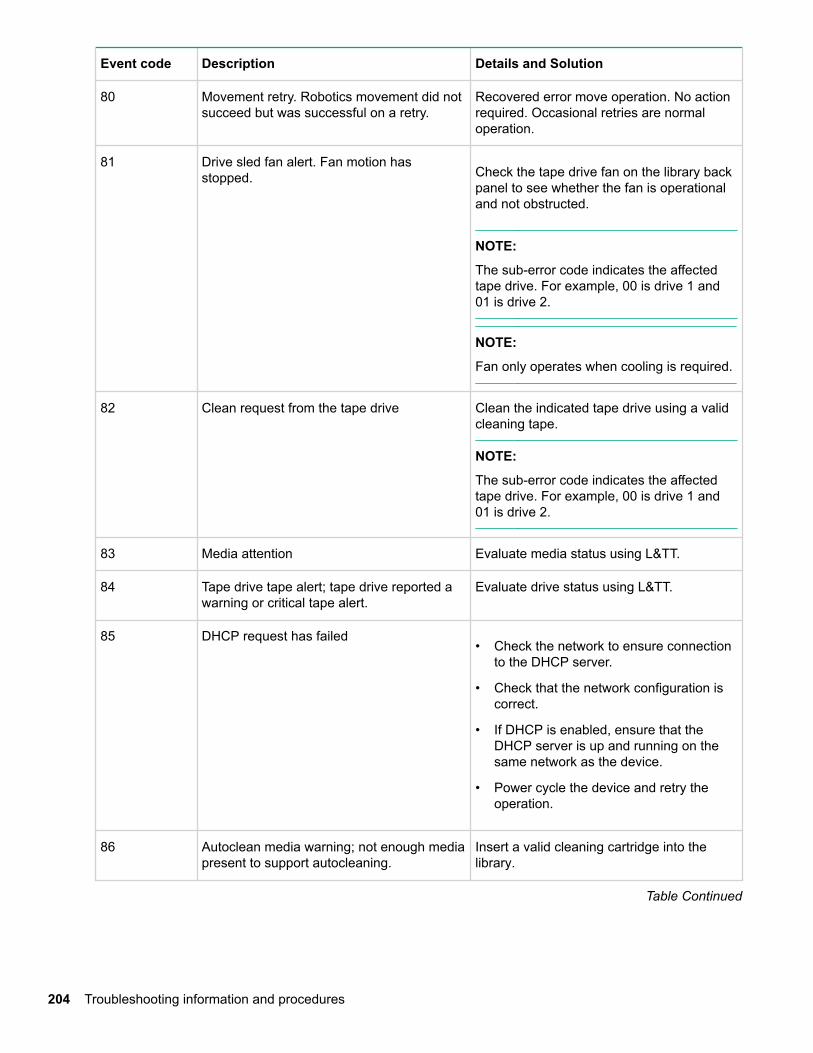
Event code Description Details and Solution
80 Movement retry. Robotics movement did notsucceed but was successful on a retry.
Recovered error move operation. No actionrequired. Occasional retries are normaloperation.
81 Drive sled fan alert. Fan motion hasstopped. Check the tape drive fan on the library back
panel to see whether the fan is operationaland not obstructed.
NOTE:
The sub-error code indicates the affectedtape drive. For example, 00 is drive 1 and01 is drive 2.
NOTE:
Fan only operates when cooling is required.
82 Clean request from the tape drive Clean the indicated tape drive using a validcleaning tape.
NOTE:
The sub-error code indicates the affectedtape drive. For example, 00 is drive 1 and01 is drive 2.
83 Media attention Evaluate media status using L&TT.
84 Tape drive tape alert; tape drive reported awarning or critical tape alert.
Evaluate drive status using L&TT.
85 DHCP request has failed• Check the network to ensure connection
to the DHCP server.
• Check that the network configuration iscorrect.
• If DHCP is enabled, ensure that theDHCP server is up and running on thesame network as the device.
• Power cycle the device and retry theoperation.
86 Autoclean media warning; not enough mediapresent to support autocleaning.
Insert a valid cleaning cartridge into thelibrary.
Table Continued
204 Troubleshooting information and procedures
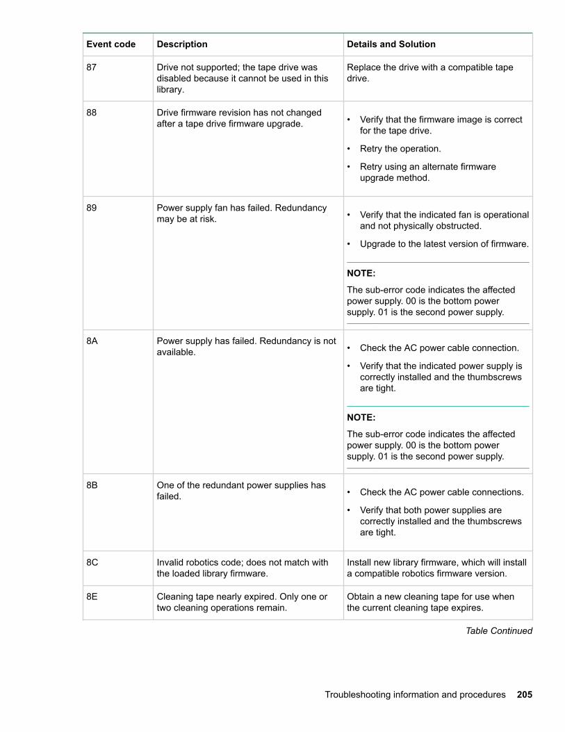
Event code Description Details and Solution
87 Drive not supported; the tape drive wasdisabled because it cannot be used in thislibrary.
Replace the drive with a compatible tapedrive.
88 Drive firmware revision has not changedafter a tape drive firmware upgrade. • Verify that the firmware image is correct
for the tape drive.
• Retry the operation.
• Retry using an alternate firmwareupgrade method.
89 Power supply fan has failed. Redundancymay be at risk. • Verify that the indicated fan is operational
and not physically obstructed.
• Upgrade to the latest version of firmware.
NOTE:
The sub-error code indicates the affectedpower supply. 00 is the bottom powersupply. 01 is the second power supply.
8A Power supply has failed. Redundancy is notavailable. • Check the AC power cable connection.
• Verify that the indicated power supply iscorrectly installed and the thumbscrewsare tight.
NOTE:
The sub-error code indicates the affectedpower supply. 00 is the bottom powersupply. 01 is the second power supply.
8B One of the redundant power supplies hasfailed. • Check the AC power cable connections.
• Verify that both power supplies arecorrectly installed and the thumbscrewsare tight.
8C Invalid robotics code; does not match withthe loaded library firmware.
Install new library firmware, which will installa compatible robotics firmware version.
8E Cleaning tape nearly expired. Only one ortwo cleaning operations remain.
Obtain a new cleaning tape for use whenthe current cleaning tape expires.
Table Continued
Troubleshooting information and procedures 205
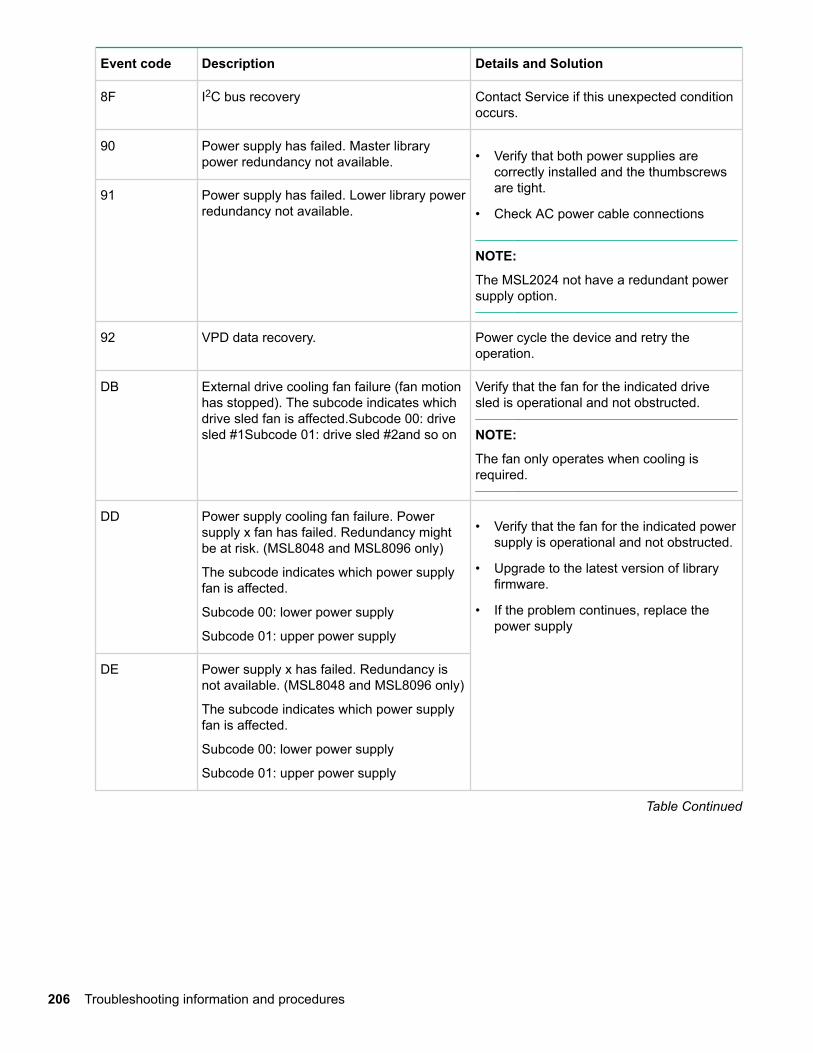
Event code Description Details and Solution
8F I2C bus recovery Contact Service if this unexpected conditionoccurs.
90 Power supply has failed. Master librarypower redundancy not available. • Verify that both power supplies are
correctly installed and the thumbscrewsare tight.
• Check AC power cable connections
NOTE:
The MSL2024 not have a redundant powersupply option.
91 Power supply has failed. Lower library powerredundancy not available.
92 VPD data recovery. Power cycle the device and retry theoperation.
DB External drive cooling fan failure (fan motionhas stopped). The subcode indicates whichdrive sled fan is affected.Subcode 00: drivesled #1Subcode 01: drive sled #2and so on
Verify that the fan for the indicated drivesled is operational and not obstructed.
NOTE:
The fan only operates when cooling isrequired.
DD Power supply cooling fan failure. Powersupply x fan has failed. Redundancy mightbe at risk. (MSL8048 and MSL8096 only)
The subcode indicates which power supplyfan is affected.
Subcode 00: lower power supply
Subcode 01: upper power supply
• Verify that the fan for the indicated powersupply is operational and not obstructed.
• Upgrade to the latest version of libraryfirmware.
• If the problem continues, replace thepower supply
DE Power supply x has failed. Redundancy isnot available. (MSL8048 and MSL8096 only)
The subcode indicates which power supplyfan is affected.
Subcode 00: lower power supply
Subcode 01: upper power supply
Table Continued
206 Troubleshooting information and procedures
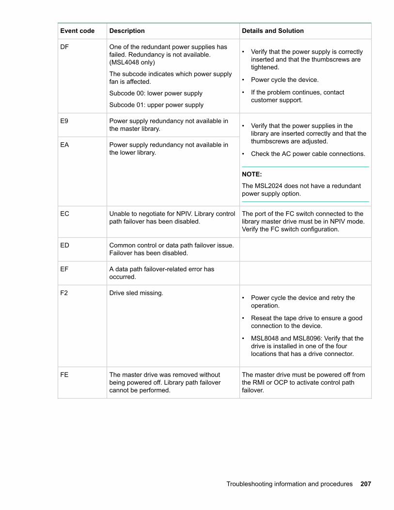
Event code Description Details and Solution
DF One of the redundant power supplies hasfailed. Redundancy is not available.(MSL4048 only)
The subcode indicates which power supplyfan is affected.
Subcode 00: lower power supply
Subcode 01: upper power supply
• Verify that the power supply is correctlyinserted and that the thumbscrews aretightened.
• Power cycle the device.
• If the problem continues, contactcustomer support.
E9 Power supply redundancy not available inthe master library. • Verify that the power supplies in the
library are inserted correctly and that thethumbscrews are adjusted.
• Check the AC power cable connections.
NOTE:
The MSL2024 does not have a redundantpower supply option.
EA Power supply redundancy not available inthe lower library.
EC Unable to negotiate for NPIV. Library controlpath failover has been disabled.
The port of the FC switch connected to thelibrary master drive must be in NPIV mode.Verify the FC switch configuration.
ED Common control or data path failover issue.Failover has been disabled.
EF A data path failover-related error hasoccurred.
F2 Drive sled missing.• Power cycle the device and retry the
operation.
• Reseat the tape drive to ensure a goodconnection to the device.
• MSL8048 and MSL8096: Verify that thedrive is installed in one of the fourlocations that has a drive connector.
FE The master drive was removed withoutbeing powered off. Library path failovercannot be performed.
The master drive must be powered off fromthe RMI or OCP to activate control pathfailover.
Troubleshooting information and procedures 207
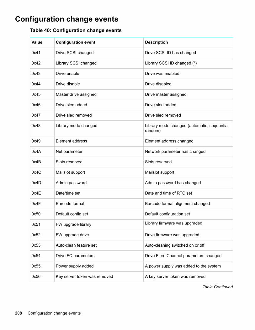
Configuration change eventsTable 40: Configuration change events
Value Configuration event Description
0x41 Drive SCSI changed Drive SCSI ID has changed
0x42 Library SCSI changed Library SCSI ID changed (*)
0x43 Drive enable Drive was enabled
0x44 Drive disable Drive disabled
0x45 Master drive assigned Drive master assigned
0x46 Drive sled added Drive sled added
0x47 Drive sled removed Drive sled removed
0x48 Library mode changed Library mode changed (automatic, sequential,random)
0x49 Element address Element address changed
0x4A Net parameter Network parameter has changed
0x4B Slots reserved Slots reserved
0x4C Mailslot support Mailslot support
0x4D Admin password Admin password has changed
0x4E Date/time set Date and time of RTC set
0x4F Barcode format Barcode format alignment changed
0x50 Default config set Default configuration set
0x51 FW upgrade library Library firmware was upgraded
0x52 FW upgrade drive Drive firmware was upgraded
0x53 Auto-clean feature set Auto-cleaning switched on or off
0x54 Drive FC parameters Drive Fibre Channel parameters changed
0x55 Power supply added A power supply was added to the system
0x56 Key server token was removed A key server token was removed
Table Continued
208 Configuration change events
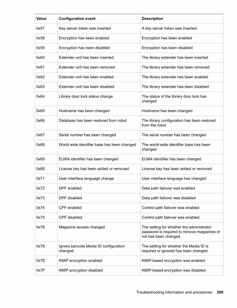
Value Configuration event Description
0x57 Key server token was inserted A key server token was inserted
0x58 Encryption has been enabled Encryption has been enabled
0x59 Encryption has been disabled Encryption has been disabled
0x60 Extender unit has been inserted The library extender has been inserted
0x61 Extender unit has been removed The library extender has been removed
0x62 Extender unit has been enabled The library extender has been enabled
0x63 Extender unit has been disabled The library extender has been disabled
0x64 Library door lock status change The status of the library door lock haschanged
0x65 Hostname has been changed Hostname has been changed
0x66 Database has been restored from robot The library configuration has been restoredfrom the robot
0x67 Serial number has been changed The serial number has been changed
0x68 World wide identifier base has been changed The world-wide identifier base has beenchanged
0x69 EUI64 identifier has been changed EUI64 identifier has been changed
0x6E License key has been added or removed License key has been added or removed
0x71 User interface language change User interface language has changed
0x72 DPF enabled Data path failover was enabled
0x73 DPF disabled Data path failover was disabled
0x74 CPF enabled Control path failover was enabled
0x75 CPF disabled Control path failover was enabled
0x76 Magazine access changed The setting for whether the administratorpassword is required to remove magazines ornot has been changed.
0x78 Ignore barcode Media ID configurationchanged
The setting for whether the Media ID isrequired or ignored has been changed.
0x7E KMIP encryption enabled KMIP-based encryption was enabled.
0x7F KMIP encryption disabled KMIP-based encryption was disabled.
Troubleshooting information and procedures 209
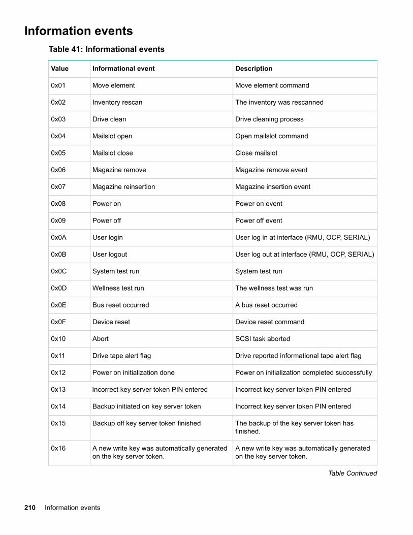
Information eventsTable 41: Informational events
Value Informational event Description
0x01 Move element Move element command
0x02 Inventory rescan The inventory was rescanned
0x03 Drive clean Drive cleaning process
0x04 Mailslot open Open mailslot command
0x05 Mailslot close Close mailslot
0x06 Magazine remove Magazine remove event
0x07 Magazine reinsertion Magazine insertion event
0x08 Power on Power on event
0x09 Power off Power off event
0x0A User login User log in at interface (RMU, OCP, SERIAL)
0x0B User logout User log out at interface (RMU, OCP, SERIAL)
0x0C System test run System test run
0x0D Wellness test run The wellness test was run
0x0E Bus reset occurred A bus reset occurred
0x0F Device reset Device reset command
0x10 Abort SCSI task aborted
0x11 Drive tape alert flag Drive reported informational tape alert flag
0x12 Power on initialization done Power on initialization completed successfully
0x13 Incorrect key server token PIN entered Incorrect key server token PIN entered
0x14 Backup initiated on key server token Incorrect key server token PIN entered
0x15 Backup off key server token finished The backup of the key server token hasfinished.
0x16 A new write key was automatically generatedon the key server token.
A new write key was automatically generatedon the key server token.
Table Continued
210 Information events
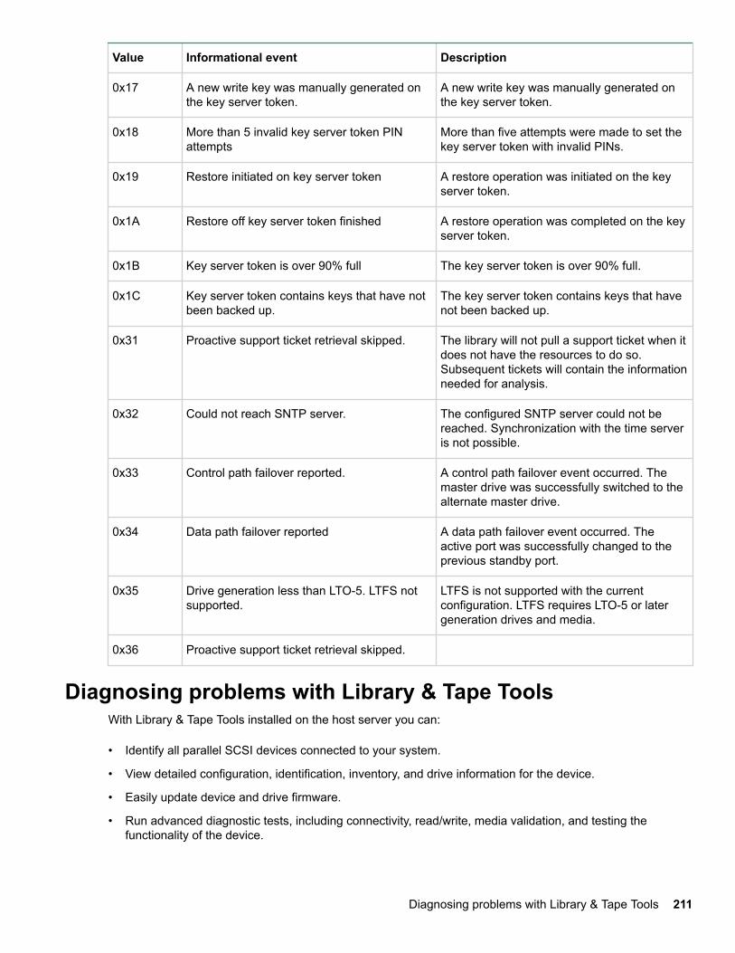
Value Informational event Description
0x17 A new write key was manually generated onthe key server token.
A new write key was manually generated onthe key server token.
0x18 More than 5 invalid key server token PINattempts
More than five attempts were made to set thekey server token with invalid PINs.
0x19 Restore initiated on key server token A restore operation was initiated on the keyserver token.
0x1A Restore off key server token finished A restore operation was completed on the keyserver token.
0x1B Key server token is over 90% full The key server token is over 90% full.
0x1C Key server token contains keys that have notbeen backed up.
The key server token contains keys that havenot been backed up.
0x31 Proactive support ticket retrieval skipped. The library will not pull a support ticket when itdoes not have the resources to do so.Subsequent tickets will contain the informationneeded for analysis.
0x32 Could not reach SNTP server. The configured SNTP server could not bereached. Synchronization with the time serveris not possible.
0x33 Control path failover reported. A control path failover event occurred. Themaster drive was successfully switched to thealternate master drive.
0x34 Data path failover reported A data path failover event occurred. Theactive port was successfully changed to theprevious standby port.
0x35 Drive generation less than LTO-5. LTFS notsupported.
LTFS is not supported with the currentconfiguration. LTFS requires LTO-5 or latergeneration drives and media.
0x36 Proactive support ticket retrieval skipped.
Diagnosing problems with Library & Tape ToolsWith Library & Tape Tools installed on the host server you can:
• Identify all parallel SCSI devices connected to your system.
• View detailed configuration, identification, inventory, and drive information for the device.
• Easily update device and drive firmware.
• Run advanced diagnostic tests, including connectivity, read/write, media validation, and testing thefunctionality of the device.
Diagnosing problems with Library & Tape Tools 211
• View device and drive error logs.
• Generate a detailed support ticket that can be e-mailed or faxed to your support representative foranalysis.
The Library & Tape Tools diagnostic provides an intuitive graphical user interface with integrated context-sensitive help. It can be downloaded free of charge from http://www.hpe.com/support/TapeTools.
Procedure
1. Run L&TT on the host server. You can install L&TT on the host server, or run it from a CD-ROM or USBflash drive on the host server.
2. Pull a support ticket for the device.
3. Look at the device analysis results for additional information about the device operation.
212 Troubleshooting information and procedures
Upgrading and servicing the libraryCAUTION:
A discharge of static electricity can damage static-sensitive devices or microcircuitry. Proper packagingand grounding techniques are necessary precautions to prevent damage.
To prevent electrostatic damage, observe the following precautions:
• Transport products in static-safe containers such as conductive tubes, bags, or boxes.
• Keep electrostatic-sensitive parts in their containers until they arrive at static-free stations.
• Cover the device with approved static-dissipating material. Provide a wrist strap connected to thework surface and properly grounded tools and equipment.
• Keep the work area free of nonconducting materials, such as ordinary plastic assembly aids andfoam packing.
• Make sure that you are always properly grounded when touching a static-sensitive component orassembly.
• Avoid touching pins, leads, or circuitry.
• Use conductive field service tools.
WARNING:
The MSL2024 weighs up to 15.6 kg (34.3 lb) without media and up to 20.4 kg (44.9 lb) with media (24cartridges). The MSL4048 weighs up to 24.6 kg (54.1 lb) without media and up to 34.2 kg (75.2 lb) withmedia (48 cartridges).
The MSL8048 tape library weighs up to 46.6 kg (102.7 lb) without media and up to 56.2 kg (122.6 lb)with media (96 cartridges). The MSL8096 tape library weighs up to 46.6 kg (102.7 lb) without media andup to 68.8 kg (151.7 lb) with media (96 cartridges).
WARNING:
To reduce the risk of personal injury or damage to equipment:
• Extend leveling jacks to the floor.
• Ensure that the full weight of the rack rests on the leveling jacks.
• Install stabilizing feet on the rack.
• Extend only one rack component at a time. If more than one component is extended, a rack canbecome unstable.
CAUTION:
Before moving the library, remove all media. During a move, the cartridges could come out of thestorage slots and damage the library.
Possible tools neededTo service the library, you might need one or more of the following tools:
Upgrading and servicing the library 213
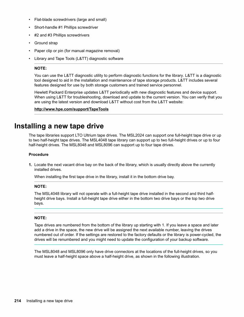
• Flat-blade screwdrivers (large and small)
• Short-handle #1 Phillips screwdriver
• #2 and #3 Phillips screwdrivers
• Ground strap
• Paper clip or pin (for manual magazine removal)
• Library and Tape Tools (L&TT) diagnostic software
NOTE:
You can use the L&TT diagnostic utility to perform diagnostic functions for the library. L&TT is a diagnostictool designed to aid in the installation and maintenance of tape storage products. L&TT includes severalfeatures designed for use by both storage customers and trained service personnel.
Hewlett Packard Enterprise updates L&TT periodically with new diagnostic features and device support.When using L&TT for troubleshooting, download and update to the current version. You can verify that youare using the latest version and download L&TT without cost from the L&TT website:
http://www.hpe.com/support/TapeTools
Installing a new tape driveThe tape libraries support LTO Ultrium tape drives. The MSL2024 can support one full-height tape drive or upto two half-height tape drives. The MSL4048 tape library can support up to two full-height drives or up to fourhalf-height drives. The MSL8048 and MSL8096 can support up to four tape drives.
Procedure
1. Locate the next vacant drive bay on the back of the library, which is usually directly above the currentlyinstalled drives.
When installing the first tape drive in the library, install it in the bottom drive bay.
NOTE:
The MSL4048 library will not operate with a full-height tape drive installed in the second and third half-height drive bays. Install a full-height tape drive either in the bottom two drive bays or the top two drivebays.
NOTE:
Tape drives are numbered from the bottom of the library up starting with 1. If you leave a space and lateradd a drive in the space, the new drive will be assigned the next available number, leaving the drivesnumbered out of order. If the settings are restored to the factory defaults or the library is power-cycled, thedrives will be renumbered and you might need to update the configuration of your backup software.
The MSL8048 and MSL8096 only have drive connectors at the locations of the full-height drives, so youmust leave a half-height space above a half-height drive, as shown in the following illustration.
214 Installing a new tape drive
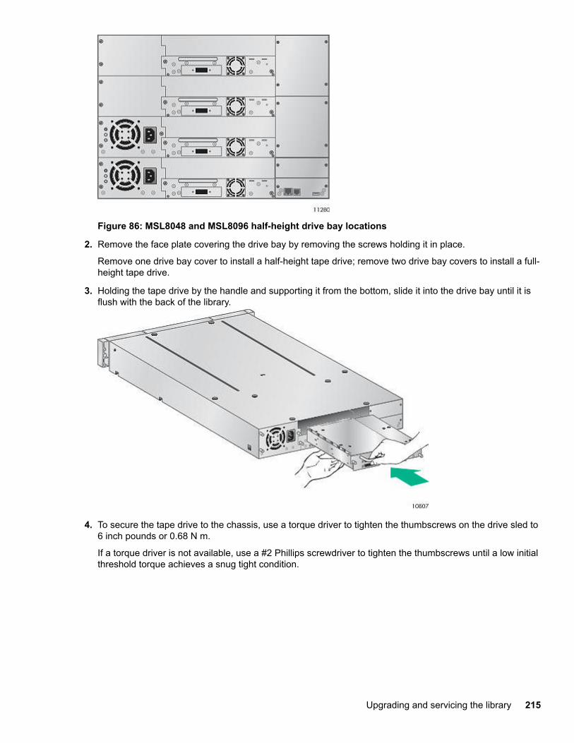
Figure 86: MSL8048 and MSL8096 half-height drive bay locations
2. Remove the face plate covering the drive bay by removing the screws holding it in place.
Remove one drive bay cover to install a half-height tape drive; remove two drive bay covers to install a full-height tape drive.
3. Holding the tape drive by the handle and supporting it from the bottom, slide it into the drive bay until it isflush with the back of the library.
4. To secure the tape drive to the chassis, use a torque driver to tighten the thumbscrews on the drive sled to6 inch pounds or 0.68 N m.
If a torque driver is not available, use a #2 Phillips screwdriver to tighten the thumbscrews until a low initialthreshold torque achieves a snug tight condition.
Upgrading and servicing the library 215
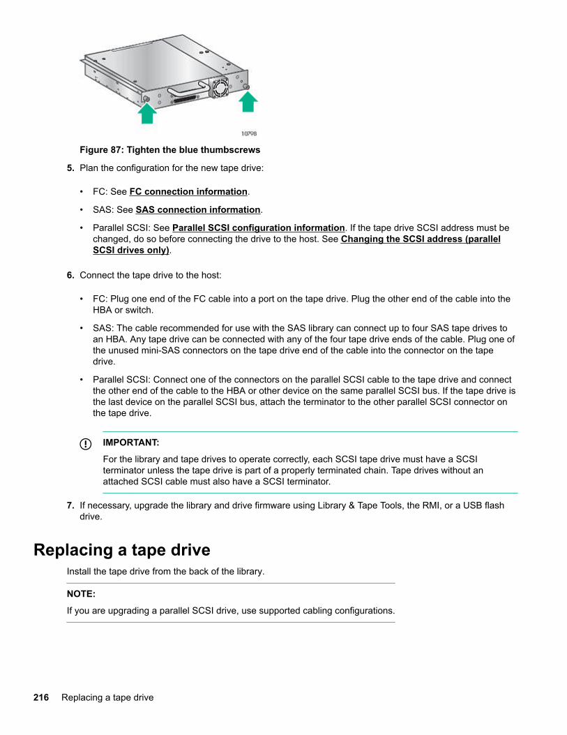
Figure 87: Tighten the blue thumbscrews
5. Plan the configuration for the new tape drive:
• FC: See FC connection information.
• SAS: See SAS connection information.
• Parallel SCSI: See Parallel SCSI configuration information. If the tape drive SCSI address must bechanged, do so before connecting the drive to the host. See Changing the SCSI address (parallelSCSI drives only).
6. Connect the tape drive to the host:
• FC: Plug one end of the FC cable into a port on the tape drive. Plug the other end of the cable into theHBA or switch.
• SAS: The cable recommended for use with the SAS library can connect up to four SAS tape drives toan HBA. Any tape drive can be connected with any of the four tape drive ends of the cable. Plug one ofthe unused mini-SAS connectors on the tape drive end of the cable into the connector on the tapedrive.
• Parallel SCSI: Connect one of the connectors on the parallel SCSI cable to the tape drive and connectthe other end of the cable to the HBA or other device on the same parallel SCSI bus. If the tape drive isthe last device on the parallel SCSI bus, attach the terminator to the other parallel SCSI connector onthe tape drive.
IMPORTANT:
For the library and tape drives to operate correctly, each SCSI tape drive must have a SCSIterminator unless the tape drive is part of a properly terminated chain. Tape drives without anattached SCSI cable must also have a SCSI terminator.
7. If necessary, upgrade the library and drive firmware using Library & Tape Tools, the RMI, or a USB flashdrive.
Replacing a tape driveInstall the tape drive from the back of the library.
NOTE:
If you are upgrading a parallel SCSI drive, use supported cabling configurations.
216 Replacing a tape drive
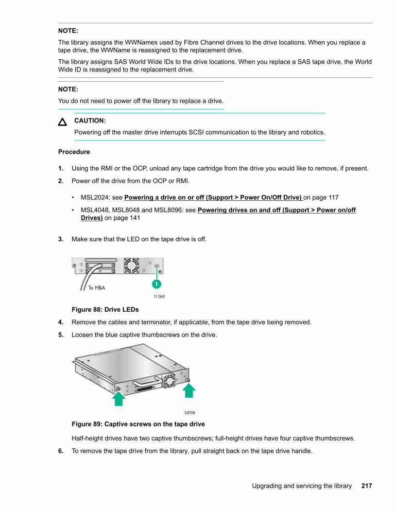
NOTE:
The library assigns the WWNames used by Fibre Channel drives to the drive locations. When you replace atape drive, the WWName is reassigned to the replacement drive.
The library assigns SAS World Wide IDs to the drive locations. When you replace a SAS tape drive, the WorldWide ID is reassigned to the replacement drive.
NOTE:
You do not need to power off the library to replace a drive.
CAUTION:
Powering off the master drive interrupts SCSI communication to the library and robotics.
Procedure
1. Using the RMI or the OCP, unload any tape cartridge from the drive you would like to remove, if present.
2. Power off the drive from the OCP or RMI.
• MSL2024: see Powering a drive on or off (Support > Power On/Off Drive) on page 117
• MSL4048, MSL8048 and MSL8096: see Powering drives on and off (Support > Power on/offDrives) on page 141
3. Make sure that the LED on the tape drive is off.
Figure 88: Drive LEDs
4. Remove the cables and terminator, if applicable, from the tape drive being removed.
5. Loosen the blue captive thumbscrews on the drive.
Figure 89: Captive screws on the tape drive
Half-height drives have two captive thumbscrews; full-height drives have four captive thumbscrews.
6. To remove the tape drive from the library, pull straight back on the tape drive handle.
Upgrading and servicing the library 217
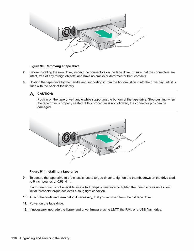
Figure 90: Removing a tape drive
7. Before installing the new drive, inspect the connectors on the tape drive. Ensure that the connectors areintact, free of any foreign objects, and have no cracks or deformed or bent contacts.
8. Holding the tape drive by the handle and supporting it from the bottom, slide it into the drive bay until it isflush with the back of the library.
CAUTION:
Push in on the tape drive handle while supporting the bottom of the tape drive. Stop pushing whenthe tape drive is properly seated. If this procedure is not followed, the connector pins can bedamaged.
Figure 91: Installing a tape drive
9. To secure the tape drive to the chassis, use a torque driver to tighten the thumbscrews on the drive sledto 6 inch pounds or 0.68 N m.
If a torque driver is not available, use a #2 Phillips screwdriver to tighten the thumbscrews until a lowinitial threshold torque achieves a snug tight condition.
10. Attach the cords and terminator, if necessary, that you removed from the old tape drive.
11. Power on the tape drive.
12. If necessary, upgrade the library and drive firmware using L&TT, the RMI, or a USB flash drive.
218 Upgrading and servicing the library
Removing and replacing a magazineCAUTION:
Only remove a magazine manually in an emergency or when removing the magazines from both sidesof the device at the same time. Failure to follow normal procedure can cause data loss and equipmentdamage.
If possible, release the magazines with the OCP or RMI. If the OCP process fails or when removing amagazine when the power to the device is off, you can release the magazines manually.
TIP:
MSL4048, MSL8048 and MSL8096: The library has multiple magazines on each side. The library willrelease all of the magazines on a side at the same time. If you want to remove more than one magazinefrom a side, pull the magazines that you are removing out a few centimeters or inches immediately afterthe library releases them. You can then remove the magazines from the library one at a time.
More information
Removing a magazine using the MSL2024 OCP on page 219
Releasing magazines using the RMI on page 220
Releasing the magazine using the manual magazine release on page 220
Removing a magazine using the MSL2024 OCP
Prerequisites
Administrator password
Procedure
1. From the Home screen, press Previous or Next until the screen displays Operations.
2. Press Enter to select.
3. Press Previous or Next until the screen displays either Unlock Left Magazine or Unlock RightMagazine.
4. Press Enter to select the desired magazine to unlock.
5. Enter the administrator password if requested.
6. The display reads Left Magazine Unlocked or Right Magazine Unlocked.
7. Pull the released magazine out of the device.
8. The screen displays Insert Left Magazine or Insert Right Magazine. The library cannot perform anyother operation until the magazine is replaced. After exchanging tapes in a magazine, slide themagazine completely into the library. The magazine locks into place after it is correctly installed and thelibrary inventories the magazine.
Removing a magazine using the MSL4048, MSL8048 and MSL8096 OCP
Prerequisites
Administrator password
Removing and replacing a magazine 219
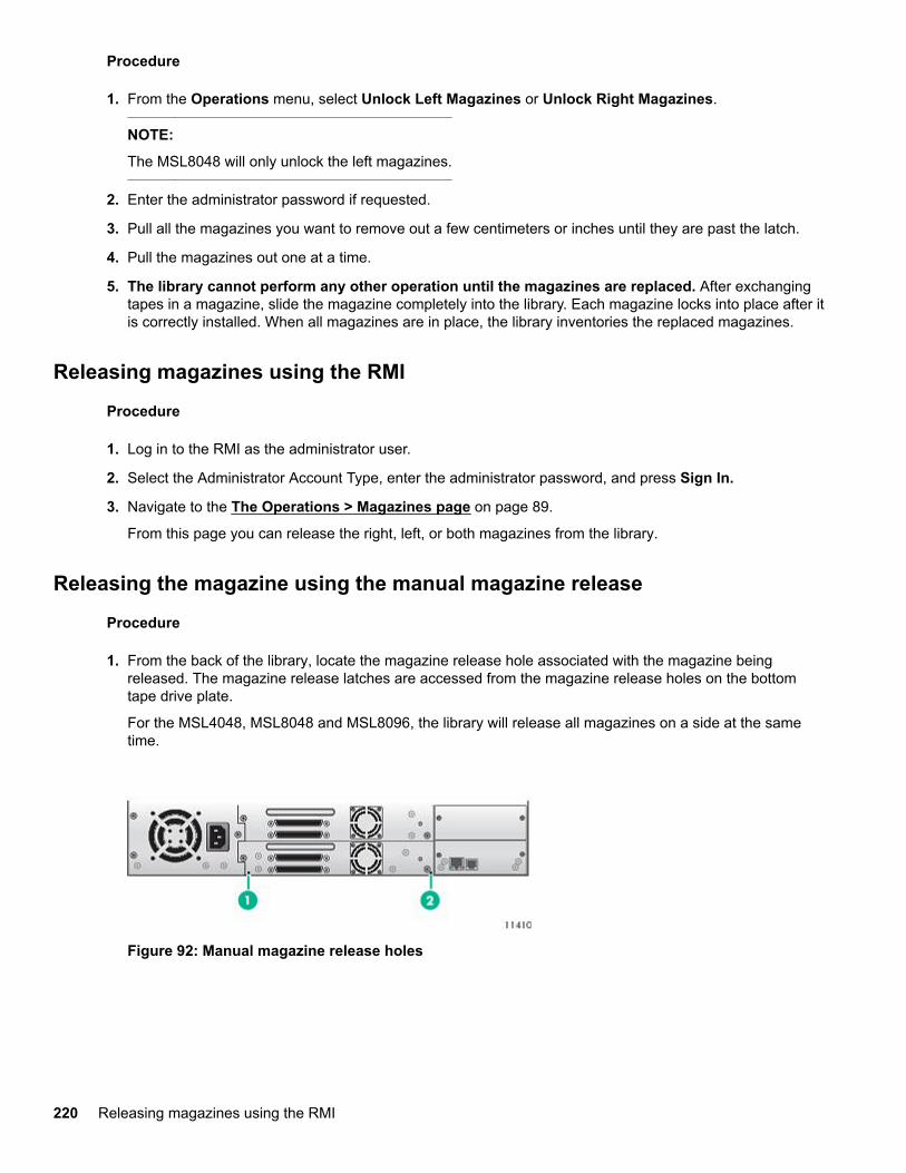
Procedure
1. From the Operations menu, select Unlock Left Magazines or Unlock Right Magazines.
NOTE:
The MSL8048 will only unlock the left magazines.
2. Enter the administrator password if requested.
3. Pull all the magazines you want to remove out a few centimeters or inches until they are past the latch.
4. Pull the magazines out one at a time.
5. The library cannot perform any other operation until the magazines are replaced. After exchangingtapes in a magazine, slide the magazine completely into the library. Each magazine locks into place after itis correctly installed. When all magazines are in place, the library inventories the replaced magazines.
Releasing magazines using the RMI
Procedure
1. Log in to the RMI as the administrator user.
2. Select the Administrator Account Type, enter the administrator password, and press Sign In.
3. Navigate to the The Operations > Magazines page on page 89.
From this page you can release the right, left, or both magazines from the library.
Releasing the magazine using the manual magazine release
Procedure
1. From the back of the library, locate the magazine release hole associated with the magazine beingreleased. The magazine release latches are accessed from the magazine release holes on the bottomtape drive plate.
For the MSL4048, MSL8048 and MSL8096, the library will release all magazines on a side at the sametime.
Figure 92: Manual magazine release holes
220 Releasing magazines using the RMI
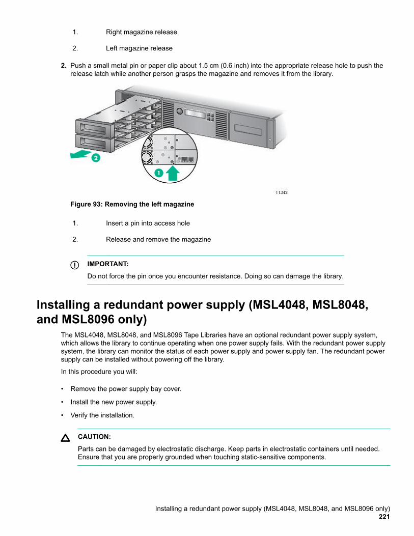
1. Right magazine release
2. Left magazine release
2. Push a small metal pin or paper clip about 1.5 cm (0.6 inch) into the appropriate release hole to push therelease latch while another person grasps the magazine and removes it from the library.
Figure 93: Removing the left magazine
1. Insert a pin into access hole
2. Release and remove the magazine
IMPORTANT:
Do not force the pin once you encounter resistance. Doing so can damage the library.
Installing a redundant power supply (MSL4048, MSL8048,and MSL8096 only)
The MSL4048, MSL8048, and MSL8096 Tape Libraries have an optional redundant power supply system,which allows the library to continue operating when one power supply fails. With the redundant power supplysystem, the library can monitor the status of each power supply and power supply fan. The redundant powersupply can be installed without powering off the library.
In this procedure you will:
• Remove the power supply bay cover.
• Install the new power supply.
• Verify the installation.
CAUTION:
Parts can be damaged by electrostatic discharge. Keep parts in electrostatic containers until needed.Ensure that you are properly grounded when touching static-sensitive components.
Installing a redundant power supply (MSL4048, MSL8048, and MSL8096 only)221
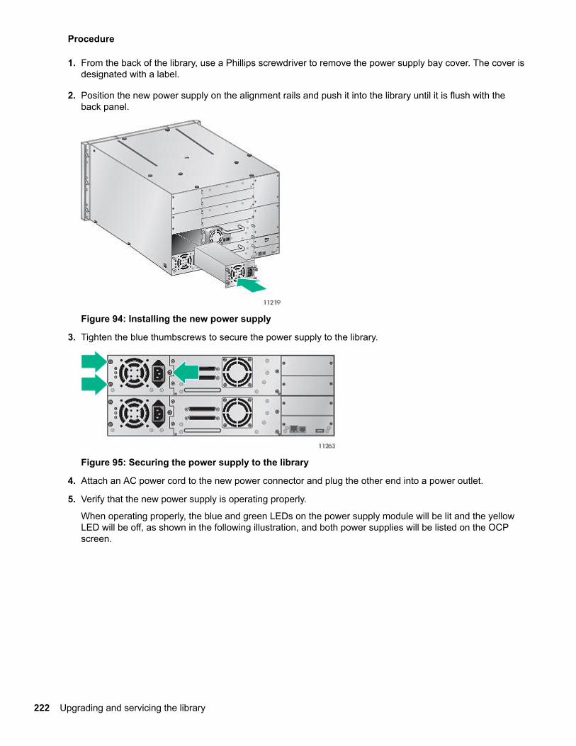
Procedure
1. From the back of the library, use a Phillips screwdriver to remove the power supply bay cover. The cover isdesignated with a label.
2. Position the new power supply on the alignment rails and push it into the library until it is flush with theback panel.
Figure 94: Installing the new power supply
3. Tighten the blue thumbscrews to secure the power supply to the library.
Figure 95: Securing the power supply to the library
4. Attach an AC power cord to the new power connector and plug the other end into a power outlet.
5. Verify that the new power supply is operating properly.
When operating properly, the blue and green LEDs on the power supply module will be lit and the yellowLED will be off, as shown in the following illustration, and both power supplies will be listed on the OCPscreen.
222 Upgrading and servicing the library
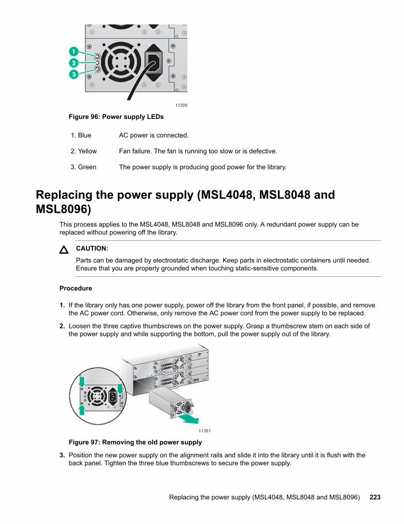
Figure 96: Power supply LEDs
1. Blue AC power is connected.
2. Yellow Fan failure. The fan is running too slow or is defective.
3. Green The power supply is producing good power for the library.
Replacing the power supply (MSL4048, MSL8048 andMSL8096)
This process applies to the MSL4048, MSL8048 and MSL8096 only. A redundant power supply can bereplaced without powering off the library.
CAUTION:
Parts can be damaged by electrostatic discharge. Keep parts in electrostatic containers until needed.Ensure that you are properly grounded when touching static-sensitive components.
Procedure
1. If the library only has one power supply, power off the library from the front panel, if possible, and removethe AC power cord. Otherwise, only remove the AC power cord from the power supply to be replaced.
2. Loosen the three captive thumbscrews on the power supply. Grasp a thumbscrew stem on each side ofthe power supply and while supporting the bottom, pull the power supply out of the library.
Figure 97: Removing the old power supply
3. Position the new power supply on the alignment rails and slide it into the library until it is flush with theback panel. Tighten the three blue thumbscrews to secure the power supply.
Replacing the power supply (MSL4048, MSL8048 and MSL8096) 223

Figure 98: Installing the new power supply
4. Verify that the new power supply is operating properly.
When a power supply with LEDs is operating properly, the blue and green LEDs on the power supplymodule are lit and the yellow LED is off. For a power supply without LEDs, verify that the power supply fanis running and the OCP does not show a warning message about the power supply.
Figure 99: Power supply LEDs
1. Blue AC power is connected.
2. Yellow Fan failure. The fan is running too slow or is defective.
3. Green The power supply is producing good power for the library.
Replacing the library controller (MSL4048, MSL8048 andMSL8096)
CAUTION:
Parts can be damaged by electrostatic discharge. Keep parts in electrostatic containers until needed.Ensure that you are properly grounded when touching static-sensitive components.
CAUTION:
This part is not hot-pluggable. Power off the library before replacing the library controller.
224 Replacing the library controller (MSL4048, MSL8048 and MSL8096)
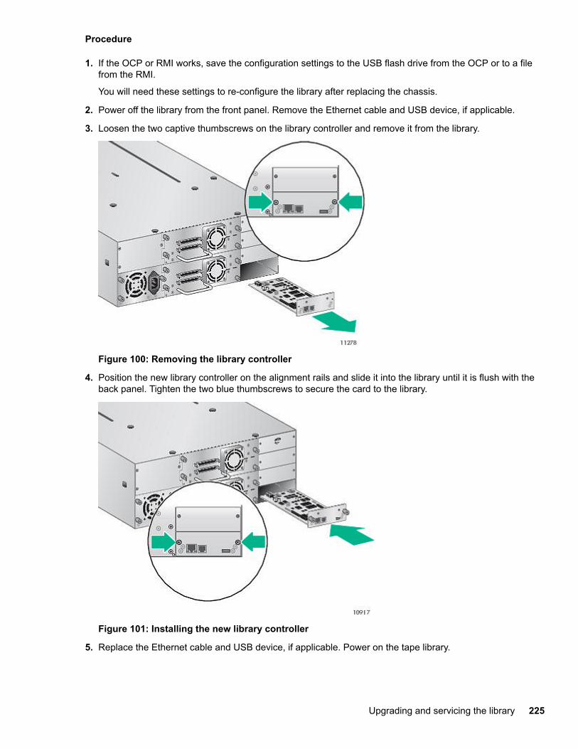
Procedure
1. If the OCP or RMI works, save the configuration settings to the USB flash drive from the OCP or to a filefrom the RMI.
You will need these settings to re-configure the library after replacing the chassis.
2. Power off the library from the front panel. Remove the Ethernet cable and USB device, if applicable.
3. Loosen the two captive thumbscrews on the library controller and remove it from the library.
Figure 100: Removing the library controller
4. Position the new library controller on the alignment rails and slide it into the library until it is flush with theback panel. Tighten the two blue thumbscrews to secure the card to the library.
Figure 101: Installing the new library controller
5. Replace the Ethernet cable and USB device, if applicable. Power on the tape library.
Upgrading and servicing the library 225
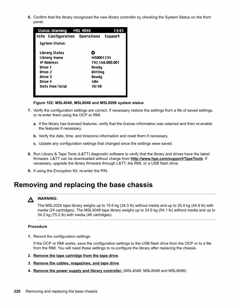
6. Confirm that the library recognized the new library controller by checking the System Status on the frontpanel.
Figure 102: MSL4048, MSL8048 and MSL8096 system status
7. Verify the configuration settings are correct. If necessary restore the settings from a file of saved settings,or re-enter them using the OCP or RMI.
a. If the library has licensed features, verify that the license information was retained and then re-enablethe features if necessary.
b. Verify the date, time, and timezone information and reset them if necessary.
c. Update any configuration settings that changed since the settings were saved.
8. Run Library & Tape Tools (L&TT) diagnostic software to verify that the library and drives have the latestfirmware. L&TT can be downloaded without charge from http://www.hpe.com/support/TapeTools. Ifnecessary, upgrade the library firmware through L&TT, the RMI, or a USB flash drive.
9. If using the Encryption Kit, re-enter the PIN.
Removing and replacing the base chassis
WARNING:
The MSL2024 tape library weighs up to 15.6 kg (34.3 lb) without media and up to 20.4 kg (44.9 lb) withmedia (24 cartridges). The MSL4048 tape library weighs up to 24.6 kg (54.1 lb) without media and up to34.2 kg (75.2 lb) with media (48 cartridges).
Procedure
1. Record the configuration settings.
If the OCP or RMI works, save the configuration settings to the USB flash drive from the OCP or to a filefrom the RMI. You will need these settings to re-configure the library after replacing the chassis.
2. Remove the tape cartridge from the tape drive.
3. Remove the cables, magazines, and tape drive.
4. Remove the power supply and library controller. (MSL4048, MSL8048 and MSL8096)
226 Removing and replacing the base chassis
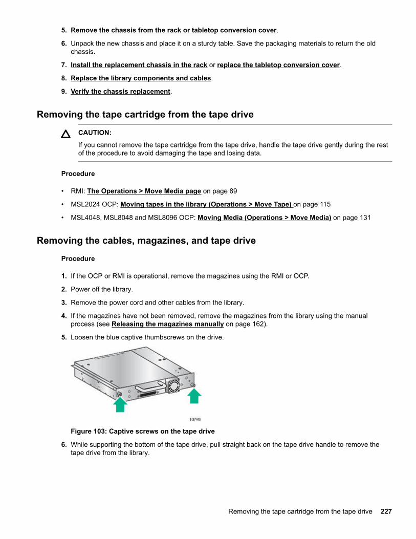
5. Remove the chassis from the rack or tabletop conversion cover.
6. Unpack the new chassis and place it on a sturdy table. Save the packaging materials to return the oldchassis.
7. Install the replacement chassis in the rack or replace the tabletop conversion cover.
8. Replace the library components and cables.
9. Verify the chassis replacement.
Removing the tape cartridge from the tape drive
CAUTION:
If you cannot remove the tape cartridge from the tape drive, handle the tape drive gently during the restof the procedure to avoid damaging the tape and losing data.
Procedure
• RMI: The Operations > Move Media page on page 89
• MSL2024 OCP: Moving tapes in the library (Operations > Move Tape) on page 115
• MSL4048, MSL8048 and MSL8096 OCP: Moving Media (Operations > Move Media) on page 131
Removing the cables, magazines, and tape drive
Procedure
1. If the OCP or RMI is operational, remove the magazines using the RMI or OCP.
2. Power off the library.
3. Remove the power cord and other cables from the library.
4. If the magazines have not been removed, remove the magazines from the library using the manualprocess (see Releasing the magazines manually on page 162).
5. Loosen the blue captive thumbscrews on the drive.
Figure 103: Captive screws on the tape drive
6. While supporting the bottom of the tape drive, pull straight back on the tape drive handle to remove thetape drive from the library.
Removing the tape cartridge from the tape drive 227
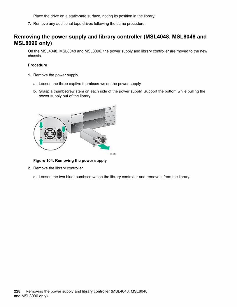
Place the drive on a static-safe surface, noting its position in the library.
7. Remove any additional tape drives following the same procedure.
Removing the power supply and library controller (MSL4048, MSL8048 andMSL8096 only)
On the MSL4048, MSL8048 and MSL8096, the power supply and library controller are moved to the newchassis.
Procedure
1. Remove the power supply.
a. Loosen the three captive thumbscrews on the power supply.
b. Grasp a thumbscrew stem on each side of the power supply. Support the bottom while pulling thepower supply out of the library.
Figure 104: Removing the power supply
2. Remove the library controller.
a. Loosen the two blue thumbscrews on the library controller and remove it from the library.
228 Removing the power supply and library controller (MSL4048, MSL8048and MSL8096 only)
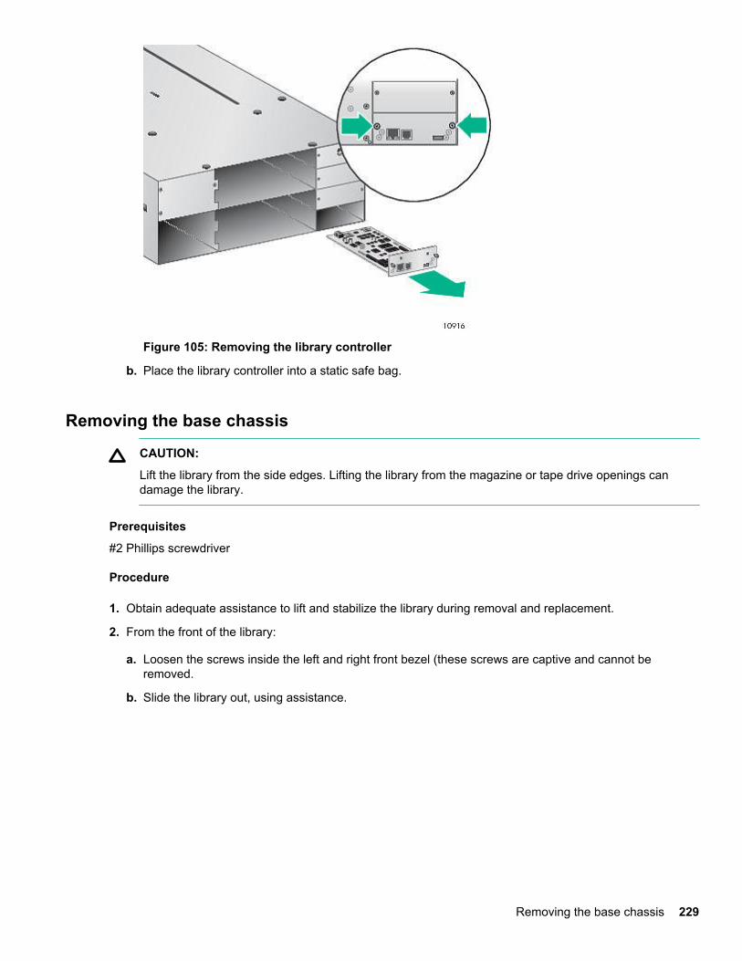
Figure 105: Removing the library controller
b. Place the library controller into a static safe bag.
Removing the base chassis
CAUTION:
Lift the library from the side edges. Lifting the library from the magazine or tape drive openings candamage the library.
Prerequisites
#2 Phillips screwdriver
Procedure
1. Obtain adequate assistance to lift and stabilize the library during removal and replacement.
2. From the front of the library:
a. Loosen the screws inside the left and right front bezel (these screws are captive and cannot beremoved.
b. Slide the library out, using assistance.
Removing the base chassis 229
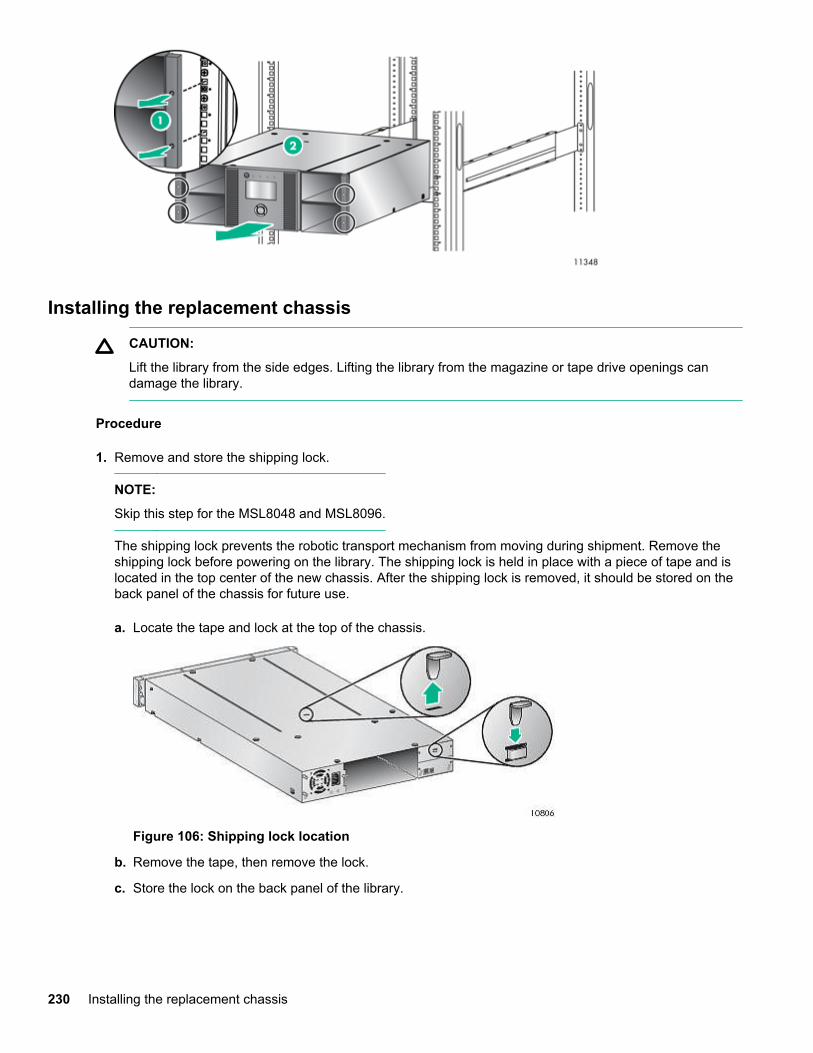
Installing the replacement chassis
CAUTION:
Lift the library from the side edges. Lifting the library from the magazine or tape drive openings candamage the library.
Procedure
1. Remove and store the shipping lock.
NOTE:
Skip this step for the MSL8048 and MSL8096.
The shipping lock prevents the robotic transport mechanism from moving during shipment. Remove theshipping lock before powering on the library. The shipping lock is held in place with a piece of tape and islocated in the top center of the new chassis. After the shipping lock is removed, it should be stored on theback panel of the chassis for future use.
a. Locate the tape and lock at the top of the chassis.
Figure 106: Shipping lock location
b. Remove the tape, then remove the lock.
c. Store the lock on the back panel of the library.
230 Installing the replacement chassis
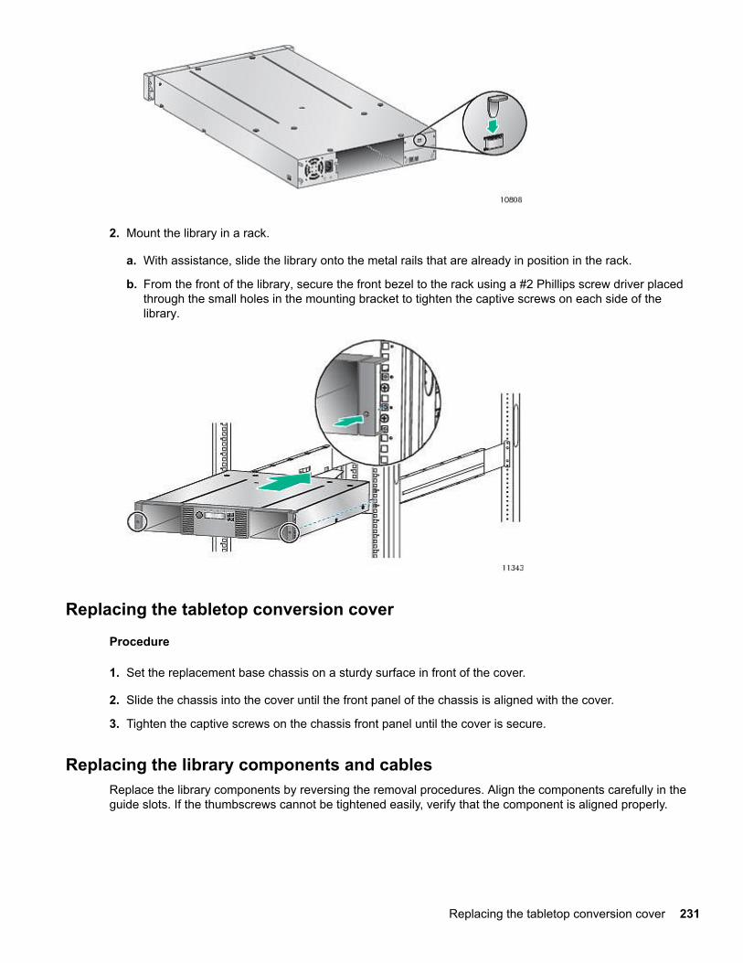
2. Mount the library in a rack.
a. With assistance, slide the library onto the metal rails that are already in position in the rack.
b. From the front of the library, secure the front bezel to the rack using a #2 Phillips screw driver placedthrough the small holes in the mounting bracket to tighten the captive screws on each side of thelibrary.
Replacing the tabletop conversion cover
Procedure
1. Set the replacement base chassis on a sturdy surface in front of the cover.
2. Slide the chassis into the cover until the front panel of the chassis is aligned with the cover.
3. Tighten the captive screws on the chassis front panel until the cover is secure.
Replacing the library components and cablesReplace the library components by reversing the removal procedures. Align the components carefully in theguide slots. If the thumbscrews cannot be tightened easily, verify that the component is aligned properly.
Replacing the tabletop conversion cover 231
Procedure
1. Replace the magazines in the same locations.
2. Replace the tape drives in the same locations.
TIP:
To assist in aligning the drive, only remove the drive bay covers for one drive at a time.
To secure the tape drive to the chassis, use a torque driver to tighten the blue captive thumbscrews on thedrive sled to 6 inch pounds or 0.68 N m.
If a torque driver is not available, use a #2 Phillips screwdriver to tighten the thumbscrews until a low initialthreshold torque achieves a snug tight condition.
3. Replace the power supplies. (MSL4048, MSL8048 and MSL8096)
4. Replace the controller board. (MSL4048, MSL8048 and MSL8096)
5. Reattach any SAS, FC, and Ethernet cables removed earlier.
6. Reinsert the USB device if you removed it earlier.
7. Reattach the power cords.
Verifying the chassis replacement
Procedure
1. Power on the library.
2. Check the overall library status from the RMI Status > Library screen.
3. Verify that the configuration settings are correct.
If necessary, restore the settings from a file or saved settings or re-enter them using the RMI or OCP.
a. If the library has licensed features, verify that the license information was retained and then re-enablethe feature.
b. Verify the date, time, and timezone information and reset them if necessary.
c. Update any configuration settings that changed since the settings were saved.
4. If using the MSL Encryption Kit, re-enter the token password.
5. Resume host applications.
232 Verifying the chassis replacement

WebsitesGeneral websitesHewlett Packard Enterprise Information Library
www.hpe.com/info/EILSingle Point of Connectivity Knowledge (SPOCK) Storage compatibility matrix
www.hpe.com/storage/spockStorage white papers and analyst reports
www.hpe.com/storage/whitepapers
For additional websites, see Support and other resources.
Websites 233
Support and other resources
Accessing Hewlett Packard Enterprise Support• For live assistance, go to the Contact Hewlett Packard Enterprise Worldwide website:
http://www.hpe.com/assistance
• To access documentation and support services, go to the Hewlett Packard Enterprise Support Centerwebsite:
http://www.hpe.com/support/hpesc
Information to collect
• Technical support registration number (if applicable)
• Product name, model or version, and serial number
• Operating system name and version
• Firmware version
• Error messages
• Product-specific reports and logs
• Add-on products or components
• Third-party products or components
Accessing updates• Some software products provide a mechanism for accessing software updates through the product
interface. Review your product documentation to identify the recommended software update method.
• To download product updates:
Hewlett Packard Enterprise Support Centerwww.hpe.com/support/hpesc
Hewlett Packard Enterprise Support Center: Software downloadswww.hpe.com/support/downloads
Software Depotwww.hpe.com/support/softwaredepot
• To subscribe to eNewsletters and alerts:
www.hpe.com/support/e-updates
• To view and update your entitlements, and to link your contracts and warranties with your profile, go to theHewlett Packard Enterprise Support Center More Information on Access to Support Materials page:
www.hpe.com/support/AccessToSupportMaterials
234 Support and other resources
IMPORTANT:
Access to some updates might require product entitlement when accessed through the Hewlett PackardEnterprise Support Center. You must have an HPE Passport set up with relevant entitlements.
Customer self repairHewlett Packard Enterprise customer self repair (CSR) programs allow you to repair your product. If a CSRpart needs to be replaced, it will be shipped directly to you so that you can install it at your convenience.Some parts do not qualify for CSR. Your Hewlett Packard Enterprise authorized service provider willdetermine whether a repair can be accomplished by CSR.
For more information about CSR, contact your local service provider or go to the CSR website:
http://www.hpe.com/support/selfrepair
Remote supportRemote support is available with supported devices as part of your warranty or contractual supportagreement. It provides intelligent event diagnosis, and automatic, secure submission of hardware eventnotifications to Hewlett Packard Enterprise, which will initiate a fast and accurate resolution based on yourproduct's service level. Hewlett Packard Enterprise strongly recommends that you register your device forremote support.
If your product includes additional remote support details, use search to locate that information.
Remote support and Proactive Care informationHPE Get Connected
www.hpe.com/services/getconnectedHPE Proactive Care services
www.hpe.com/services/proactivecareHPE Proactive Care service: Supported products list
www.hpe.com/services/proactivecaresupportedproductsHPE Proactive Care advanced service: Supported products list
www.hpe.com/services/proactivecareadvancedsupportedproducts
Proactive Care customer informationProactive Care central
www.hpe.com/services/proactivecarecentralProactive Care service activation
www.hpe.com/services/proactivecarecentralgetstarted
Warranty informationTo view the warranty for your product or to view the Safety and Compliance Information for Server, Storage,Power, Networking, and Rack Products reference document, go to the Enterprise Safety and Compliancewebsite:
www.hpe.com/support/Safety-Compliance-EnterpriseProducts
Additional warranty informationHPE ProLiant and x86 Servers and Options
www.hpe.com/support/ProLiantServers-Warranties
Customer self repair 235
HPE Enterprise Serverswww.hpe.com/support/EnterpriseServers-Warranties
HPE Storage Productswww.hpe.com/support/Storage-Warranties
HPE Networking Productswww.hpe.com/support/Networking-Warranties
Regulatory informationTo view the regulatory information for your product, view the Safety and Compliance Information for Server,Storage, Power, Networking, and Rack Products, available at the Hewlett Packard Enterprise Support Center:
www.hpe.com/support/Safety-Compliance-EnterpriseProducts
Additional regulatory information
Hewlett Packard Enterprise is committed to providing our customers with information about the chemicalsubstances in our products as needed to comply with legal requirements such as REACH (Regulation EC No1907/2006 of the European Parliament and the Council). A chemical information report for this product can befound at:
www.hpe.com/info/reach
For Hewlett Packard Enterprise product environmental and safety information and compliance data, includingRoHS and REACH, see:
www.hpe.com/info/ecodata
For Hewlett Packard Enterprise environmental information, including company programs, product recycling,and energy efficiency, see:
www.hpe.com/info/environment
Documentation feedbackHewlett Packard Enterprise is committed to providing documentation that meets your needs. To help usimprove the documentation, send any errors, suggestions, or comments to Documentation Feedback([email protected]). When submitting your feedback, include the document title, part number, edition,and publication date located on the front cover of the document. For online help content, include the productname, product version, help edition, and publication date located on the legal notices page.
236 Regulatory information
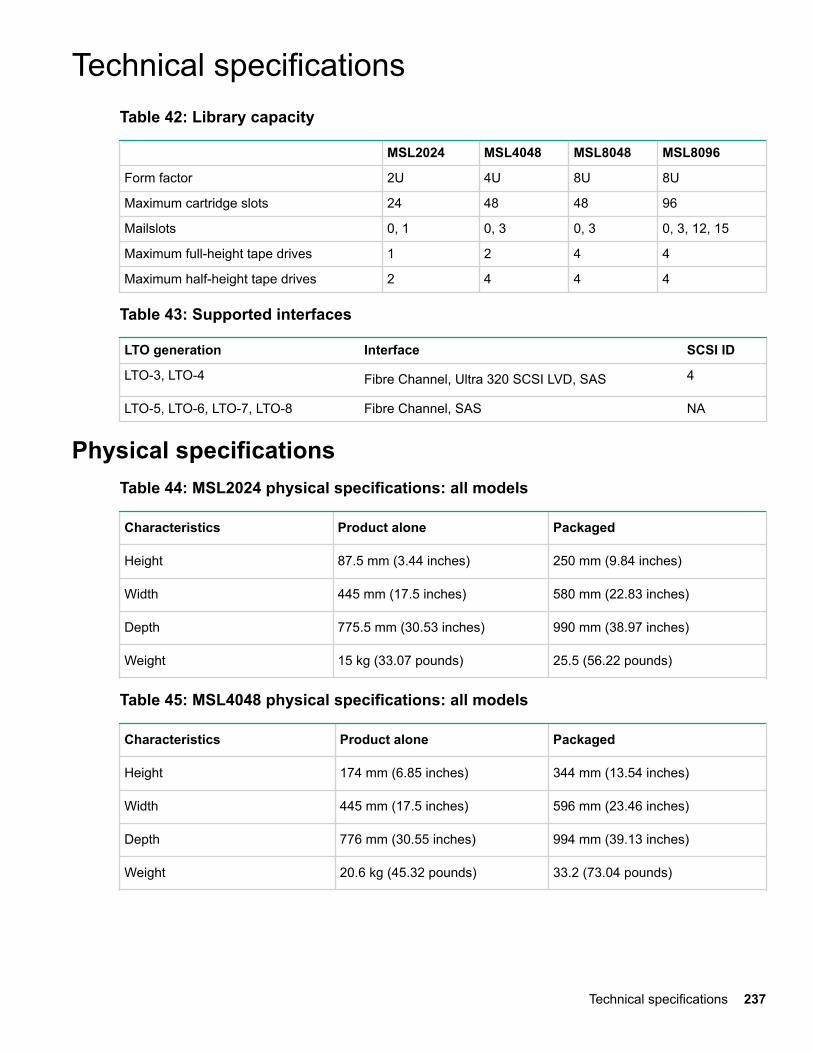
Technical specificationsTable 42: Library capacity
MSL2024 MSL4048 MSL8048 MSL8096
Form factor 2U 4U 8U 8U
Maximum cartridge slots 24 48 48 96
Mailslots 0, 1 0, 3 0, 3 0, 3, 12, 15
Maximum full-height tape drives 1 2 4 4
Maximum half-height tape drives 2 4 4 4
Table 43: Supported interfaces
LTO generation Interface SCSI ID
LTO-3, LTO-4 Fibre Channel, Ultra 320 SCSI LVD, SAS 4
LTO-5, LTO-6, LTO-7, LTO-8 Fibre Channel, SAS NA
Physical specificationsTable 44: MSL2024 physical specifications: all models
Characteristics Product alone Packaged
Height 87.5 mm (3.44 inches) 250 mm (9.84 inches)
Width 445 mm (17.5 inches) 580 mm (22.83 inches)
Depth 775.5 mm (30.53 inches) 990 mm (38.97 inches)
Weight 15 kg (33.07 pounds) 25.5 (56.22 pounds)
Table 45: MSL4048 physical specifications: all models
Characteristics Product alone Packaged
Height 174 mm (6.85 inches) 344 mm (13.54 inches)
Width 445 mm (17.5 inches) 596 mm (23.46 inches)
Depth 776 mm (30.55 inches) 994 mm (39.13 inches)
Weight 20.6 kg (45.32 pounds) 33.2 (73.04 pounds)
Technical specifications 237

Table 46: MSL8048 and MSL8096 Tape Library physical specifications: all models
Characteristics Product alone Packaged
Height 352 mm (13.86 inches) 533 mm (20.98 inches)
Width 480 mm (18.9 inches) 589 mm (23.19 inches)
Depth 806 mm (31.73 inches) 987 mm (38.86 inches)
Weight 46.6 kg (102.7 pounds) 66.6 (146.8 pounds)
Environmental specificationsTable 47: Environmental specifications
Characteristic Specification
LTO-7 and LTO-8 LTO-5 and LTO-6
Temperature
Operating 10° to 35° C up to 3000 m
10° to 30° C above 3000 m and up to4000 m
10° to 35° C
Storage -30° to 60° C
Temperature shockimmunity — maximum rateof change
10° C per hour
Miscellaneous
Dust concentration ISO 14644 -1 Class 8 less than 200 microgram / cubic meter
Altitude 4000 meters (see operatingtemperature)
4000 meters
Humidity
Operating 20% to 80% RH (noncondensing, max wet bulb temperature = 26C)
Nonoperating 10% to 90% RH noncondensing 10% to 95% RH noncondensing
Electrical specificationsPower
• MSL2024: 168 Watts (max)
• MSL4048, MSL8048 and MSL8096: 312 Watts (max)
238 Environmental specifications
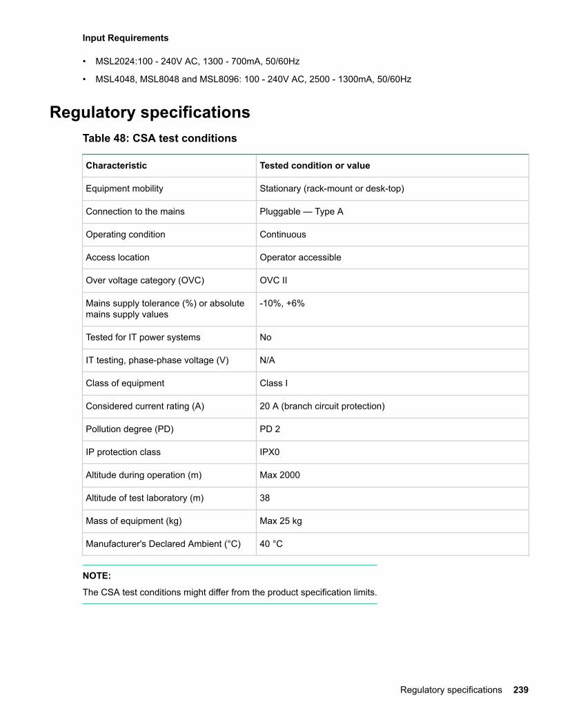
Input Requirements
• MSL2024:100 - 240V AC, 1300 - 700mA, 50/60Hz
• MSL4048, MSL8048 and MSL8096: 100 - 240V AC, 2500 - 1300mA, 50/60Hz
Regulatory specificationsTable 48: CSA test conditions
Characteristic Tested condition or value
Equipment mobility Stationary (rack-mount or desk-top)
Connection to the mains Pluggable — Type A
Operating condition Continuous
Access location Operator accessible
Over voltage category (OVC) OVC II
Mains supply tolerance (%) or absolutemains supply values
-10%, +6%
Tested for IT power systems No
IT testing, phase-phase voltage (V) N/A
Class of equipment Class I
Considered current rating (A) 20 A (branch circuit protection)
Pollution degree (PD) PD 2
IP protection class IPX0
Altitude during operation (m) Max 2000
Altitude of test laboratory (m) 38
Mass of equipment (kg) Max 25 kg
Manufacturer's Declared Ambient (°C) 40 °C
NOTE:
The CSA test conditions might differ from the product specification limits.
Regulatory specifications 239
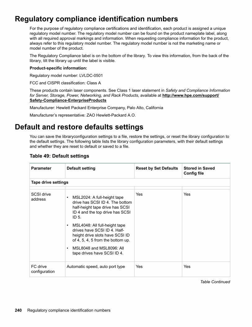
Regulatory compliance identification numbersFor the purpose of regulatory compliance certifications and identification, each product is assigned a uniqueregulatory model number. The regulatory model number can be found on the product nameplate label, alongwith all required approval markings and information. When requesting compliance information for the product,always refer to this regulatory model number. The regulatory model number is not the marketing name ormodel number of the product.
The Regulatory Compliance label is on the bottom of the library. To view this information, from the back of thelibrary, tilt the library up until the label is visible.
Product-specific information:
Regulatory model number: LVLDC-0501
FCC and CISPR classification: Class A
These products contain laser components. See Class 1 laser statement in Safety and Compliance Informationfor Server, Storage, Power, Networking, and Rack Products, available at http://www.hpe.com/support/Safety-Compliance-EnterpriseProducts
Manufacturer: Hewlett Packard Enterprise Company, Palo Alto, California
Manufacturer’s representative: ZAO Hewlett-Packard A.O.
Default and restore defaults settingsYou can save the libraryconfiguration settings to a file, restore the settings, or reset the library configuration tothe default settings. The following table lists the library configuration parameters, with their default settingsand whether they are reset to default or saved to a file.
Table 49: Default settings
Parameter Default setting Reset by Set Defaults Stored in SavedConfig file
Tape drive settings
SCSI driveaddress • MSL2024: A full-height tape
drive has SCSI ID 4. The bottomhalf-height tape drive has SCSIID 4 and the top drive has SCSIID 5.
• MSL4048: All full-height tapedrives have SCSI ID 4. Half-height drive slots have SCSI IDof 4, 5, 4, 5 from the bottom up.
• MSL8048 and MSL8096: Alltape drives have SCSI ID 4.
Yes Yes
FC driveconfiguration
Automatic speed, auto port type Yes Yes
Table Continued
240 Regulatory compliance identification numbers
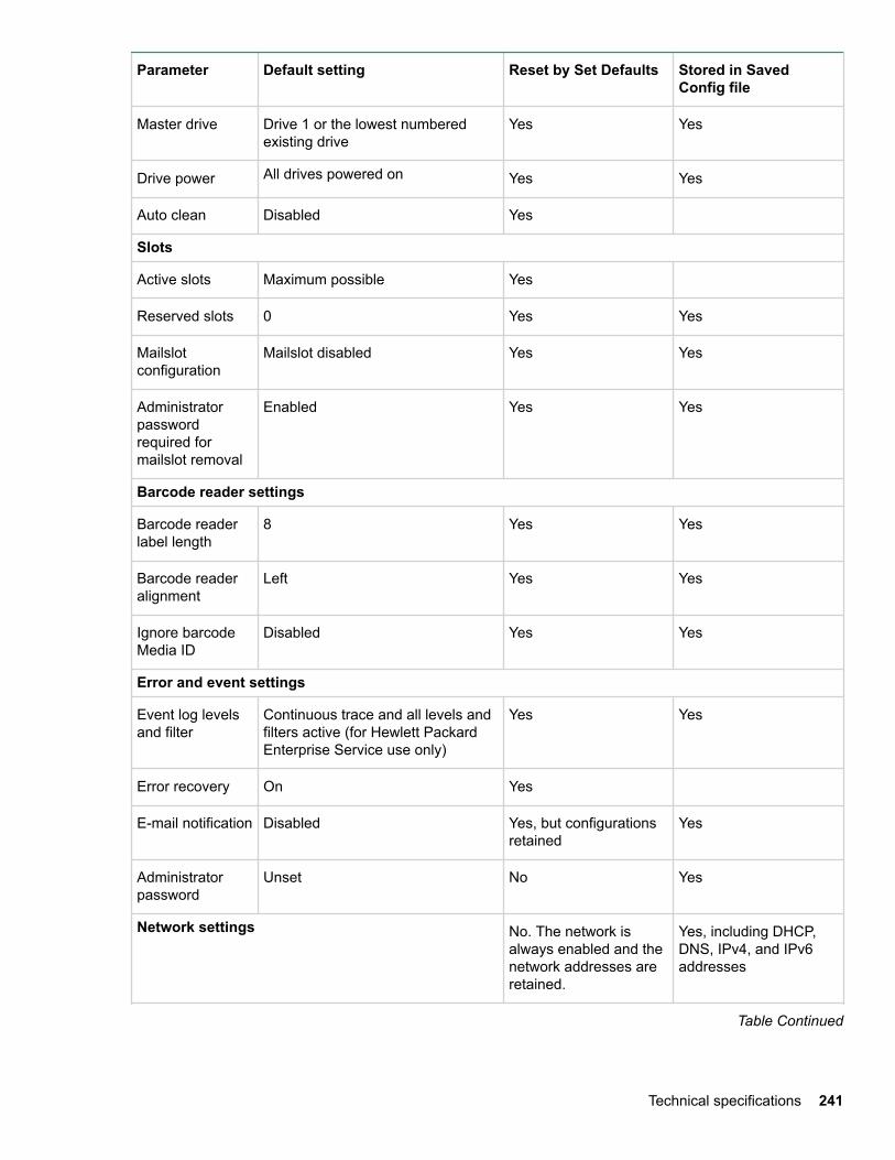
Parameter Default setting Reset by Set Defaults Stored in SavedConfig file
Master drive Drive 1 or the lowest numberedexisting drive
Yes Yes
Drive power All drives powered on Yes Yes
Auto clean Disabled Yes
Slots
Active slots Maximum possible Yes
Reserved slots 0 Yes Yes
Mailslotconfiguration
Mailslot disabled Yes Yes
Administratorpasswordrequired formailslot removal
Enabled Yes Yes
Barcode reader settings
Barcode readerlabel length
8 Yes Yes
Barcode readeralignment
Left Yes Yes
Ignore barcodeMedia ID
Disabled Yes Yes
Error and event settings
Event log levelsand filter
Continuous trace and all levels andfilters active (for Hewlett PackardEnterprise Service use only)
Yes Yes
Error recovery On Yes
E-mail notification Disabled Yes, but configurationsretained
Yes
Administratorpassword
Unset No Yes
Network settings No. The network isalways enabled and thenetwork addresses areretained.
Yes, including DHCP,DNS, IPv4, and IPv6addresses
Table Continued
Technical specifications 241
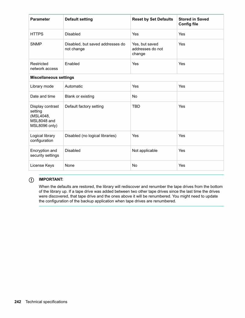
Parameter Default setting Reset by Set Defaults Stored in SavedConfig file
HTTPS Disabled Yes Yes
SNMP Disabled, but saved addresses donot change
Yes, but savedaddresses do notchange
Yes
Restrictednetwork access
Enabled Yes Yes
Miscellaneous settings
Library mode Automatic Yes Yes
Date and time Blank or existing No
Display contrastsetting(MSL4048,MSL8048 andMSL8096 only)
Default factory setting TBD Yes
Logical libraryconfiguration
Disabled (no logical libraries) Yes Yes
Encryption andsecurity settings
Disabled Not applicable Yes
License Keys None No Yes
IMPORTANT:
When the defaults are restored, the library will rediscover and renumber the tape drives from the bottomof the library up. If a tape drive was added between two other tape drives since the last time the driveswere discovered, that tape drive and the ones above it will be renumbered. You might need to updatethe configuration of the backup application when tape drives are renumbered.
242 Technical specifications
Electrostatic dischargeTo prevent damaging the system, be aware of and follow precautions when setting up the system or handlingparts. A discharge of static electricity from a finger or other conductor may damage system boards or otherstatic-sensitive devices. This type of damage may reduce the life expectancy of the device.
Preventing electrostatic damageTo prevent electrostatic damage, observe the following precautions:
• Avoid hand contact by transporting and storing products in static-safe containers.
• Keep electrostatic-sensitive parts in their containers until they arrive at static-free workstations.
• Place parts on a grounded surface before removing them from their containers.
• Avoid touching pins, leads, or circuitry.
• Always be properly grounded when touching a static-sensitive component or assembly. See the nextsection.
Grounding methodsThere are several methods for grounding. Use one or more of the following methods when handling orinstalling electrostatic-sensitive parts:
• Use a wrist strap connected by a ground cord to a grounded workstation or computer chassis. Wrist strapsare flexible straps with a minimum of 1 megohm (±10 percent) resistance in the ground cords. To provideproper ground, wear the strap snug against the skin.
• Use heel straps, toe straps, or boot straps at standing workstations. Wear the straps on both feet whenstanding on conductive floors or dissipating floor mats.
• Use conductive field service tools.
• Use a portable field service kit with a folding static-dissipating work mat.
If you do not have any of the suggested equipment for proper grounding, have your Hewlett PackardEnterprise authorized reseller install the part.
NOTE:
For more information on static electricity, or assistance with product installation, contact your Hewlett PackardEnterprise authorized reseller.
Electrostatic discharge 243

Warranty and regulatory informationFor important safety, environmental, and regulatory information, see Safety and Compliance Information forServer, Storage, Power, Networking, and Rack Products, available at www.hpe.com/support/Safety-Compliance-EnterpriseProducts.
Warranty informationHPE ProLiant and x86 Servers and Options
www.hpe.com/support/ProLiantServers-Warranties
HPE Enterprise Servers
www.hpe.com/support/EnterpriseServers-Warranties
HPE Storage Products
www.hpe.com/support/Storage-Warranties
HPE Networking Products
www.hpe.com/support/Networking-Warranties
Regulatory information
Belarus Kazakhstan Russia marking
Manufacturer and Local Representative Information
Manufacturer information:
Hewlett Packard Enterprise Company, 3000 Hanover Street, Palo Alto, CA 94304 U.S.
Local representative information Russian:
• Russia
:
• Belarus
:
• Kazakhstan
244 Warranty and regulatory information

:
Local representative information Kazakh:
• Russia
:
• Belarus
:
• Kazakhstan
:
Manufacturing date:
The manufacturing date is defined by the serial number.
CCSYWWZZZZ (serial number format for this product)
Valid date formats include:
• YWW, where Y indicates the year counting from within each new decade, with 2000 as the starting point;for example, 238: 2 for 2002 and 38 for the week of September 9. In addition, 2010 is indicated by 0, 2011by 1, 2012 by 2, 2013 by 3, and so forth.
• YYWW, where YY indicates the year, using a base year of 2000; for example, 0238: 02 for 2002 and 38 forthe week of September 9.
Turkey RoHS material content declaration
Ukraine RoHS material content declaration
Turkey RoHS material content declaration 245