Embed Size (px)
Citation preview

Trimble 3600-seriesUser Guide
Part
no.
: 57
1 70
3 00
1


1
Inhalt
Dear Customer................................................... 1-1 The system philosophy ...................................... 1-1 Important notes................................................. 1-2
Hardware overview................................2-2 Hardware overview .................................. 2-2 Control Unit ............................................. 2-3 Options.................................................... 2-3 DR Version Direct Reflex EDM and Laser Poin-ter (Option)................................................... 2-4 Additional trigger key............................... 2-5 Laser Plummet (Option) ........................... 2-5 PositionLight (Option) .............................. 2-6
Safety Notes...........................................2-7 Risks in use .............................................. 2-7 Laser beam safety .................................... 2-8 Laser beam safety Laser Plummet ............. 2-9 Laser beam safety Position Light............. 2-10 Laser beam safety Infrared-Interface....... 2-10 Laser beam safety EDM in Direct Reflex Mode .................... 2-11 Laser beam safety EDM in Prism Mode ............................... 2-11 Laser beam safety Laser Pointer .............. 2-12 Laser beam safety hints on the instrument ......................... 2-12
Technical Data......................................2-13 Trimble 3602 Trimble 3603.................... 2-13 Electromagnetic Compatibility (EMV) ..... 2-16 Battery Charger LG 20............................ 2-17 Charging the battery .............................. 2-18 Instructions for Maintenance and Care... 2-19
1 Introduction
2 Trimble 3600 The System In-strument Description

2

1-1
1 Introduction
Dear Customer
By purchasing a Trimble 3600 series total sta-tion you have opted for a leading-edge product in the field of surveying instruments.
We congratulate you on your choice and would like to thank you for the trust placed in our com-pany.
The system philosophy
Surveying today is no longer confined to the measurement of angles and distances. A demand now exists for complex measuring systems which not only meet the increasing requirements for automatization, digital data processing and last but not least efficiency in everyday surveying, but which also set new standards in technology and operating convenience.
The Trimble 3600 series total stations are part of a complete range of surveying instruments from Trimble The operating convenience offered by the Trimble 3600 hardware is unique in total stations. The large graphic display and handy keyboard give the user a high degree of flexibility for the proc-essing of the wide variety of information in the measurement dialog.
The different Control Units meet all requirements.

1-2
Introduction
Important notes
The instrument was manufactured by tested methods and using environmentally compatible quality materials.
The mechanical, optical and electronic functions of the instrument were carefully checked prior to delivery. Should any defects attributable to faulty material or workmanship occur within the war-ranty period, they will be repaired as a warranty service.
This warranty does not cover defects caused by operator errors or improper handling.
Any further liabilities, e.g. for indirect damages, cannot be accepted.
!!!! Attention ! Attention ! Attention ! Attention !
Please read the safety notes in chapter 2 carefully before starting up the instrument.
User Manual User Manual User Manual User Manual Trimble 3600Trimble 3600Trimble 3600Trimble 3600 1111stststst Part Part Part Part
Edition 1:Edition 1:Edition 1:Edition 1: 15.02.200115.02.200115.02.200115.02.2001
Cat.Cat.Cat.Cat. No.: No.: No.: No.: 571 703 001571 703 001571 703 001571 703 001

1-3
Introduction
Europe:
Phone: +49-6142-21000 Telefax:: +49-6142-2100 220 E-mail: [email protected] Homepage: http://www.trimble.com
"
#### Tip Tip Tip Tip
The type label and serial number are pro-vided on the left-hand side and underside of the instrument respectively. Please note this data and the following information in your user manual. Always indicate this reference in any inquiries addressed to our dealer, agency or service department:
Instrument: Instrument: Instrument: Instrument: Control Unit Control Unit Control Unit Control Unit
$ Trimble 3602 $ Zeiss Elta
$ Trimble 3603 $ CU 600 numeric
$ CU 600 alphanum. Serial number:
If you have any software-related questions (CU Zeiss Elta only), please also state the version of the relevant software package installed in your instrument:
Software version:
Please note your autohorisation code for the software packages::
Basic Expert
Professional Special
Professional Plus!

1-4
Introduction
We would like to wish you every success in your work with your Trimble 3600. If you need any help, we will be glad to be of assistance.
Yours
ZSP Geodetic Systems GmbH Carl-Zeiss-Promenade 10 D-07745 Jena Tel.: ++49 3641 64-3200 Fax: ++49 3641 64 3229 E-Mail: [email protected] http://www.trimble.com

2-1
2 Trimble 3600 The System
This chapter gives you an overview of the instru-ment hardware.
It describes the operation and controls of the instrument as well as the sensors and peripheries which are a special feature of the Trimble 3600 total stations.
Instrument Description
Safety Notes
Technical Data

2-2
Instrument Description
Hardware overview
1 Handle
2 Sighting collimator
3 Telescope focusing control
4 Crosshair focusing control
5 Eyepiece
6 Battery clamp
7 Battery
8 Trigger key for measurement
9 Tribrach with footscrews
10 Keyboard
11 Display (graphical, 320 x 80 pixel)
12 Telescope with integrated electro-optical distance meter
14 Optical plummet
15 Circular level
16 RS232C (V24) cable interface and exter-nal battery port (with Zeiss Elta only)
17 Serial infrared interface (with Zeiss Elta only)
18 Quick Drive Fine coarse Hz
19 Quick Drive Fine coarse V
20 Position Light
Fig. 1: Trimble 3600
Fig. 2: Trimble 3600
2
7
18 15
10
17
11
19
12
1
8
3
4
5
10
11 14
2
16
6
7
9

2-3
Instrument Description
Control Unit
The instruments are each available in three con-figurations, with the following features being standard in all versions:
• Zeiss Elta CU MS-DOS® PC with 486 processor, Graphic display with 320x80 pixel, Infra-red interface for wireless data trans- fer
• CU 600 numeric (removable) Graphical LCD display with 4 lines and 20 columns illuminated. 22 keys.
• CU 600 alphanumeric (removable) Graphical LCD display with 4 lines and 20 columns illuminated. 33 keys.
Options
• Optical plummet for instrument center-ing
• Position Light - the optical aid for align-ing the prism in setting out.
• Laser plummet – for centering the instrument by the help of a laser pointer.

2-4
Instrument Description
DR Version Direct Reflex EDM and Laser Pointer (Option)
A instrument with known Prism Mode (PR) is equiped with:
• Direct Reflex Mode (DR) with Laser Pointer
DR DR DR DR –––– Mode (Option) Mode (Option) Mode (Option) Mode (Option) ---- measurement without measurement without measurement without measurement without prismprismprismprism
Prism Prism Prism Prism ---- Mode (Standard) Mode (Standard) Mode (Standard) Mode (Standard) ---- measurement with measurement with measurement with measurement with prismprismprismprism

2-5
Instrument Description
Additional trigger key
The key located on the right-hand side of the instrument, below the motorized drives, permits you to trigger measurements. This is particularly useful when measuring in the reverse position.
Laser Plummet (Option)
The Laser Plummet is used to center the instru-ment over a station point. The plummet is a Laser Pen with an additional optical element which illustrates a center circle on the ground. The in-strument has to be moved on the tripod head for centering over the station point.
The Laser Center Circle has a diameter of 45 mm at an instrument height of 1,5 m.
! Additional trigger key
!!!! Attention! Attention! Attention! Attention!
Never look directly into the laser beam! Please read the given warnings and hints for laser beam safety in this chapter.

2-6
Instrument Description
Position Light (Option)
Position Light is the optical aid for aligning the prism in setting out. Position Light helps to find the setting out position by optical illumination signals.
Seen from the prism poll means:
green Position Light: left from the point
red Position Light: right from the point
If the setting out direction (da=0) is reached, the green light is very closed to the red light (merg-ing).
If distance-tracking is switched on and the setting out direction is reached, you can control the length differences by the help of the Position Light blink-frequency. (Zeiss Elta Control Unit Only)
Light signals:
fast blinking: in front of the point
slower blinking: behind the point
In the left figure the setting out positions 1- 4 will be shown on the prism poll as follows:
1 green light
2 red light
3 signal fast blinking
4 signal slowly blinking
P Set out point, constant light, green-red
At a distance of ±10 cm to the setting out point P Position Light has a constant light signal.
Position Light
P da=0
4
3
1 2
2-7
Safety Notes
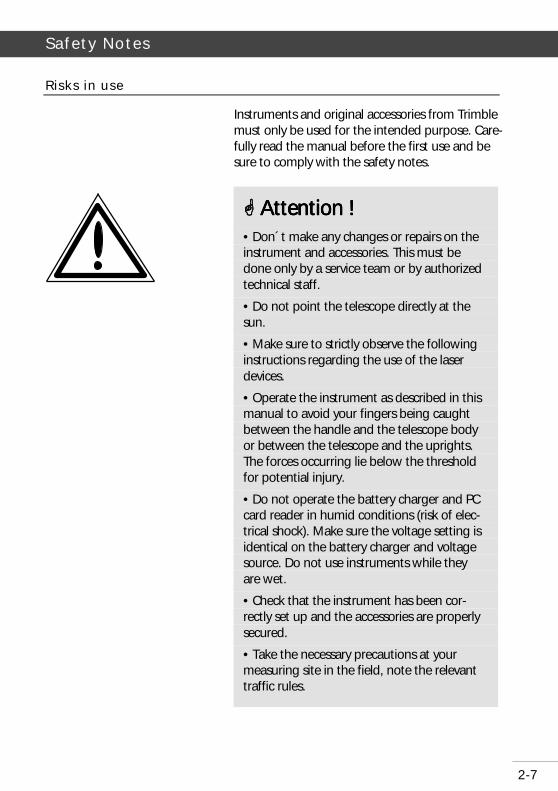
Risks in use
Instruments and original accessories from Trimble must only be used for the intended purpose. Care-fully read the manual before the first use and be sure to comply with the safety notes.
!!!! Attenti Attenti Attenti Attention !on !on !on ! • Don´t make any changes or repairs on the instrument and accessories. This must be done only by a service team or by authorized technical staff.
• Do not point the telescope directly at the sun.
• Make sure to strictly observe the following instructions regarding the use of the laser devices.
• Operate the instrument as described in this manual to avoid your fingers being caught between the handle and the telescope body or between the telescope and the uprights. The forces occurring lie below the threshold for potential injury.
• Do not operate the battery charger and PC card reader in humid conditions (risk of elec-trical shock). Make sure the voltage setting is identical on the battery charger and voltage source. Do not use instruments while they are wet.
• Check that the instrument has been cor-rectly set up and the accessories are properly secured.
• Take the necessary precautions at your measuring site in the field, note the relevant traffic rules.

2-8
Safety Notes
Laser beam safety
!!!! Attention ! Attention ! Attention ! Attention ! • Check your instrument at regular intervals in order to avoid faulty measurements, espe-cially after it has been subjected to shock or heavy punishment.
• The instrument and accessories must only be opened by a service team or by author-ized technical staff.
• Remove the batteries in case of unloading or a longer time without using the instru-ment.
• Properly dispose of the batteries and equipment taking into account the applica-ble national regulations.
• Do not use destroyed plugs and cables for accessories with the instrument.
• Do not use the instrument and accessories in rooms with danger of explosion.
If used for the intended purpose, and if correctly operated and properly maintained, the lasers pro-vided in the instruments are not hazardous to the eye.
!!!! Attention Attention Attention Attention
Repairs must only be performed at a service workshop authorized by Trimble.

2-9
Safety Notes
Laser beam safety Laser Plummet
- Beam divergence: 3.5 mrad - Pulse duration: 17.5 ms (dimming) *) - Max. output power: 1.0 mW - Wavelengths: 635 nm - Measuring uncertainty: ± 5 % - *) not for Trimble 3600 Zeiss Elta
The Laser Plummet pro-duces a visible laser beam emerging from vertical axis below the instrument. Con-forms to Class 2 in acc. with DIN- EN 60 825 - 1: March 1997 "Safety of laser de-vices".
!!!! Attention ! Attention ! Attention ! Attention !
Direct viewing of the beam must be avoided under all circumstances!
A shortly protection is given by the eyelid close reflex.
LASER RADIATIONLASER RADIATIONLASER RADIATIONLASER RADIATION DO NOT STARE INTO THE BEAMDO NOT STARE INTO THE BEAMDO NOT STARE INTO THE BEAMDO NOT STARE INTO THE BEAM CLASS 2 LASER PRODUCTCLASS 2 LASER PRODUCTCLASS 2 LASER PRODUCTCLASS 2 LASER PRODUCT MAX. OUTPUT POWER:MAX. OUTPUT POWER:MAX. OUTPUT POWER:MAX. OUTPUT POWER: 1.0 mW1.0 mW1.0 mW1.0 mW LIGHT WAVELENGTH: LIGHT WAVELENGTH: LIGHT WAVELENGTH: LIGHT WAVELENGTH: 635 nm635 nm635 nm635 nm DINDINDINDIN----EN 60 825EN 60 825EN 60 825EN 60 825----1 MARCH 19971 MARCH 19971 MARCH 19971 MARCH 1997
2-10
Safety Notes
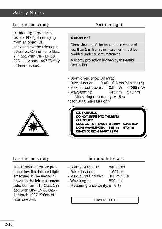
Laser beam safety Position Light
- Beam divergence: 80 mrad - Pulse duration: 0.05 – 0.5 ms (blinking) *) - Max. output power: 0.8 mW 0.065 mW - Wavelengths: 645 nm 570 nm - Measuring uncertainty: ± 5 % *) for 3600 Zeiss Elta only
Laser beam safety Infrared-Interface
- Beam divergence: 840 mrad - Pulse duration: 1.627 µs - Max. output power: 400 mW / sr - Wavelength: 890 nm - Measuring uncertainty: ± 5 %
Position Light produces visible LED light emerging from an objective above/below the telescope objective. Conforms to Class 2 in acc. with DIN- EN 60 825 - 1: March 1997 "Safety of laser devices".
!!!! Attention ! Attention ! Attention ! Attention !
Direct viewing of the beam at a distance of less than 1 m from the instrument must be avoided under all circumstances.
A shortly protection is given by the eyelid close reflex.
The infrared-interface pro-duces invisible infrared-light emerging at the two win-dows on the left instrument side. Conforms to Class 1 in acc. with DIN- EN 60 825 - 1: March 1997 "Safety of laser devices".
LED RADIATIONLED RADIATIONLED RADIATIONLED RADIATION DO NOT STARE IDO NOT STARE IDO NOT STARE IDO NOT STARE INTO THE BEAMNTO THE BEAMNTO THE BEAMNTO THE BEAM CLASS 2 LED CLASS 2 LED CLASS 2 LED CLASS 2 LED MAX. OUTPUT POWER: 0.8 mW 0.065 mW MAX. OUTPUT POWER: 0.8 mW 0.065 mW MAX. OUTPUT POWER: 0.8 mW 0.065 mW MAX. OUTPUT POWER: 0.8 mW 0.065 mW LIGHT WAVELENGTH: 645 nm 570 nmLIGHT WAVELENGTH: 645 nm 570 nmLIGHT WAVELENGTH: 645 nm 570 nmLIGHT WAVELENGTH: 645 nm 570 nm DINDINDINDIN----EN 60 825EN 60 825EN 60 825EN 60 825----1 MARCH 19971 MARCH 19971 MARCH 19971 MARCH 1997
Class 1 LED

2-11
Safety Notes
Laser beam safety EDM in Direct Reflex Mode
- Beam divergence: 0,4 mrad - Pulse duration: 3 ns - Max. output power: 1 mW - Wavelength: 660 nm - Measuring uncertainty: ± 5 %
Laser beam safety EDM in Prism Mode
- Beam divergence: 0,4 mrad - Pulse duration: 3 ns - Max. output power: 17 µW - Wavelength: 660 nm - Measuring uncertainty: ± 5 %
The EDM in Direct Reflex Mode produces visible Laser light emerging at the center of the telescope objective. Conforms to Class 2 in acc. with DIN- EN 60 825 - 1: March 1997 "Safety of laser devices".
!!!! Attention ! Attention ! Attention ! Attention !
Direct viewing of the beam must be avoided under all circumstances.
A shortly protection is given by the eyelid close reflex.
The EDM in Prism Mode produces visible Laser light emerging at the center of the telescope objective.
Conforms to Class 1 in acc. with DIN- EN 60 825-1: March 1997 "Safety of laser devices".
LASER RADIATIONLASER RADIATIONLASER RADIATIONLASER RADIATION DO NOT STARE INTO THE BEAMDO NOT STARE INTO THE BEAMDO NOT STARE INTO THE BEAMDO NOT STARE INTO THE BEAM CLASS 2 LASER PRODUCTCLASS 2 LASER PRODUCTCLASS 2 LASER PRODUCTCLASS 2 LASER PRODUCT MAX. OUTPUT POWER: 1.0 mWMAX. OUTPUT POWER: 1.0 mWMAX. OUTPUT POWER: 1.0 mWMAX. OUTPUT POWER: 1.0 mW LIGHT WAVELENGTH: 660 nmLIGHT WAVELENGTH: 660 nmLIGHT WAVELENGTH: 660 nmLIGHT WAVELENGTH: 660 nm DINDINDINDIN----EN 60 825EN 60 825EN 60 825EN 60 825----1 MARCH 19971 MARCH 19971 MARCH 19971 MARCH 1997
CLASS 1 LASERPRODUCT

2-12
Safety Notes
Laser beam safety Laser Pointer
- Beam divergence: 0,4 mrad - Pulse duration: 3 ns - Max. output power: 1 mW - Wavelength: 660 nm - Measuring uncertainty: ± 5 %
Laser beam safety hints on the instrument
The Laser beam safety notes are given at the but-ton of the instrument and near the telescope objective.
The Laser Pointer produces visible Laser light emerging at the center of the tele-scope objective. Conforms to Class 2 in acc. with DIN- EN 60 825 - 1: March 1997 "Safety of laser devices".
!!!! Attention Attention Attention Attention !!!!
Direct viewing of the beam must be avoided under all circumstances.
A shortly protection is given by the eyelid close reflex.
LASER RADIATIONLASER RADIATIONLASER RADIATIONLASER RADIATION DO NOT STARE INTO THE BEAMDO NOT STARE INTO THE BEAMDO NOT STARE INTO THE BEAMDO NOT STARE INTO THE BEAM CLASS 2 LASER CLASS 2 LASER CLASS 2 LASER CLASS 2 LASER PRODUCTPRODUCTPRODUCTPRODUCT MAX. OUTPUT POWER: 1.0 mWMAX. OUTPUT POWER: 1.0 mWMAX. OUTPUT POWER: 1.0 mWMAX. OUTPUT POWER: 1.0 mW LIGHT WAVELENGTH: 660 nmLIGHT WAVELENGTH: 660 nmLIGHT WAVELENGTH: 660 nmLIGHT WAVELENGTH: 660 nm DINDINDINDIN----EN 60 825EN 60 825EN 60 825EN 60 825----1 MARCH 19971 MARCH 19971 MARCH 19971 MARCH 1997

2-13
Technical Data
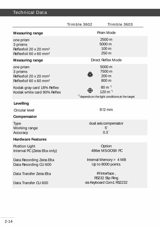
Trimble 3602 Trimble 3603
0.7 mgrad (2“ ) 1.0 mgrad (3“ ) 0.01 mgrad
2 mm + 2 ppm 3 mm + 2 ppm 5 mm + 2 ppm 3 mm + 2 ppm 5 mm + 2 ppm 10 mm + 2 ppm
30 x 1.2°
2.2 m 1.5 m
electronic, absolute 360° (DMS, DEG), 400 grads, 6400 mils
zenith-, height and vertical angle , slope in percent
electro-optical, modulated infrared light coaxial, in telescope
0.1 mm 0.4 mrad
< 2.0 s < 1.8 s < 0.4 s < 3.0 s < 2.0 s < 0.8 s
Accuracy as per DIN 18723
Angle measurement Smallest last unit
Distance measurement PR Normal PR Rapid PR Tracking DR Normal DR Rapid DR Tracking
Telescope
Magnification Aperture Field of view at 100 m Shortest sighting
Angle measurement
Hz- and V-circles Measuring units Vertical reference systems
Distance measurement
Method Transmitter/Receiver optics Resolution Divergenz Measurement time PR Normal*) PR Rapid *) PR Tracking*) DR Normal*) DR Rapid *) DR Tracking*) *) depending from the measure-ment conditions
2-14
Technical Data
Trimble 3602 Trimble 3603
Prism Mode
2500 m 5000 m 100 m 250 m
Direct Reflex Mode
5000 m 7500 m 200 m 800 m
80 m *) 120 m *)
*) depends on the light conditions at the target
8’/2 mm
dual axis compensator 5’
0.3 ‘’
Option 486er MS-DOS® PC
Internal Memory > 4 MB
Up to 8000 points.
IR Interface , RS232 Slip Ring
via Keyboard Com1 RS2232
Measuring range
one prism 3 prisms Reflexfoil 20 x 20 mm² Reflexfoil 60 x 60 mm²
Measuring range
one prism 3 prisms Reflexfoil 20 x 20 mm² Reflexfoil 60 x 60 mm²
Kodak gray card 18% Reflex Kodak white card 90% Reflex
Levelling
Circular level
Compensator
Type Working range Accuracy
Hardware Features
Position Light Internal PC (Zeiss Elta only) Data Recording Zeiss Elta Data Recording CU 600 Data Transfer Zeiss Elta Data Transfer CU 600

2-15
Technical Data
Trimble 3602 Trimble 3603
8 lines by 40 columns, CGA graphic display (320x80 pixels), illuminated, 28 keys optional 2nd display face available
22 keys; 4 line LCD 20 character / line; illuminated
33 keys 4 line LCD 20 character / line; illuminated
Co-axial, friction clamp with endless fine coarse
Zeiss / Wild
Option
Option
Internal: NiMH battery pack 6 V/3.5 Ah; External: NiCd battery 6 V/7.0 Ah;
internal battery takes approx. 1.5 hours external battery takes 3.5 hours
-20°C to +50°C
220 x 370 x 185 mm
175 mm/ 196 mm
< 6,7 kg < 6,7 kg
Display screen / keyboard
Zeiss Elta
Cu 600 numeric
CU 600 alphanumeric Centering and Positioning
Coarses
Centering
Optical Plummet
Laser Plummet
Power Supply
Charging with LG 20 of an empty
Operating temperatures
Dimensions
Instrument (WxHxD) Trunnion axis height with DIN centering spigot/ Wild centering
Weight
Zeiss Elta CU Geodimeter

2-16
Technical Data
Electromagnetic Compatibility (EMV)
Interference suppression as per: EN 55022 class B
Noise immunity: EN 50082-2
Die EU Conformity Declara-tion confirms the perfect function of the instrument in an electromagnetic envi-ronment.
!!!! Attention ! Attention ! Attention ! Attention !
Computers and radio devices connected to the Trimble 3600 which are not part of the Trimble System delivery, have to meet the same EMV requirements in order to ensure that the overall configuration complies with the applicable interference suppression stan-dards.
"""" Tip Tip Tip Tip
Strong magnetic fields generated by mid and low voltage transformer stations possibly exceed the check criterions. Make a plausibil-ity check of the results when measuring on such conditions.

2-17
Technical Data
Battery Charger LG 20
Electrical and thermo-mechanical fuses protect instrument and battery during the operation and the battery during the charging process.
Change of battery after warning: connect a charged external battery and remove the empty internal battery from the instrument (or vice versa for empty external battery). Switch the instrument off for as long as the power supply is interrupted for the battery change.
LG 20 Universal charger for NiCd-/NiMH cells of safety class II with nominal capacity: 0.5 Ah to 7 Ah. input: 230 V ± 10 % 50 Hz or DC 12 V output: 9.00 V; 800 mA or 2000 mA DC, resp.
Battery Management
Technical Data
Safety Notes !!!! Attention! Attention! Attention! Attention!
Please, read and observe these operating instructions before using the LG 20!
Protect the LG 20 against humidity, use it in dry rooms only.
Only the service or authorized specialists are allowed to open the LG 20.
Charge temperature range: 5° to 45°C; opti-mum: 10° to 30°C.
Charge parameters (nominal charging time, charging current) set automatically by a coding resistor (in battery pack) ⇒ no over-charging, protection of instrument and bat-tery.
For operating the LG 20/1 with a 12 V bat-tery, the cable (70 84 10 - 000.000) with inte-grated fuse link delivered by the manufacturer is to be used unconditionally!

2-18
Technical Data
Charging the battery
Connect the power source with the battery dem-onstrated in the follow picture.. Note, that the voltage of the charging unit is identical with the power source.
LED flashing 3x yellow Starting
LED flashing green (max. 1.5 h)
Charging of a fully charged battery: the charging process is stopped after approx. 5 minutes. If the temperature is too high or too low the charging process is stop automatically
LED continuously lit red
the charging process is stopped; if the charging temperature range is reached again the charging process is resumed
LED continuously green lit Trickle charge
LED continuously yellow lit Stand-by mode (no battery con-nected)
Charging start
Charging procedure
End of charging process
"""" Tip Tip Tip Tip
The batteries cannot be overcharged.
230 V Battery
LG 20 (230V)
1 2 3

2-19
Technical Data
Instructions for Maintenance and Care
Allow sufficient time for the instrument to adjust to the ambient temperature.
Use a soft cloth to remove dirt and dust from the instrument.
When working in wet weather or rain, cover the instrument during longer breaks with the protec-tive hood.
Clean the optics with special care using a clean and soft cloth, cotton wool or a soft brush, do not use any liquid except pure alcohol.
Do not touch the optical surface with the fingers.
Steamed prisms must have sufficient time to ad-just to the ambient temperature. Remove after-wards the moisture using a clean and soft cloth.
For transportation over long distances, the in-strument should be stored in its case.
When working in wet weather, wipe the instru-ment and case dry in the field and let it dry com-pletely indoors, with the case open.
If, for the purpose of changing the station, the instrument with the tripod is transported on the shoulder, please make sure that instrument and person will not be damaged or injured.
Let wet instruments and accessories dry before packing them up.
After a long storage, check the adjustment of the instrument prior to use.
Observe the boundary values for the temperature of storing, especially in the summer (interior of the vehicle).
Instrument
Object lens and eyepiece
Prisms
Transportation
Storage

2-20


ZSP Geodetic Systems GmbHCarl-Zeiss-Promenade 10D-07745 JenaGermany
Phone: +49 3641 64-3200Fax: + 49 3641 64-3229email: [email protected]