Embed Size (px)
Citation preview
1
USER GUIDE
Publication AP9250_4
2
XONE23 User Guide AP9250 Issue 4
Copyright copy 2018 Allen amp Heath Limited All rights reserved
Allen amp Heath Limited
Kernick Industrial Estate Penryn Cornwall TR10 9LU UK
wwwallen-heathcom
Limited One Year Manufacturerrsquos Warranty
Allen amp Heath warrants the Allen amp Heath - branded hardware product and accessories contained in the original packaging (Allen amp Heath Productrdquo) against defects in materi-als and workmanship when used in accordance with Allen amp Heaths user manuals tech-nical specifications and other Allen amp Heath product published guidelines for a period of ONE (1) YEAR from the date of original purchase by the end-user purchaser (Warranty Period)
This warranty does not apply to any non-Allen amp Heath branded hardware products or any software even if packaged or sold with Allen amp Heath hardware Please refer to the licensing agreement accompanying the software for details of your rights with respect to the use of software (ldquoEULArdquo) Details of the EULA warranty policy and other useful information can be found on the Allen amp Heath website wwwallen-heathcomlegal
Repair or replacement under the terms of the warranty does not provide right to extension or renewal of the warranty period Repair or direct replacement of the product under the terms of this warranty may be fulfilled with functionally equivalent service exchange units
This warranty is not transferable This warranty does not cover fader wear and tear
This warranty will be the purchaserrsquos sole and exclusive remedy and neither Allen amp Heath nor its approved service centres shall be liable for any incidental or consequential damages or breach of any express or implied warranty of this product
Conditions of Warranty The equipment has not been subject to misuse either intended or accidental neglect or alteration other than as described in the User Guide or Service Manual or approved by Al-len amp Heath Any necessary adjustment alteration or repair has been carried out by an authorised Allen amp Heath distributor or agent The defective unit is to be returned carriage prepaid to the place of purchase an author-ised Allen amp Heath distributor or agent with proof of purchase Please discuss this with the distributor or the agent before shipping If the unit is to be repaired in a different country to that of its purchase the repair may take longer than normal whilst the warranty is con-firmed and parts are sourced Units returned should be packed in the original carton to avoid transit damage In certain territories the terms may vary Check with your Allen amp Heath distributor or agent for any additional warranty information which may apply If further assistance is required please contact Allen amp Heath Ltd
DISCLAIMER Allen amp Heath shall not be liable for the loss of any savedstored data in products that are either repaired or replaced
XONE23 complies with the European Electromagnetic Compatibility directives
201430EU and the European Low Voltage directives 201435EU
Any changes or modifications to the equipment not approved by Allen amp Heath could void the compliance of the product and therefore the users authority to operate it
3
PACKED ITEMS
Check that you have received the following
Safety Sheet
Important Read this sheet before starting
Retain for future reference
Power Supply
12V - 25 Amps
Xone23 mixer
Power supply IEC Lead
This is country specific and will vary with mains voltageterritory
4
CONTENTS
Congratulations on purchasing the Allen amp Heath Xone23 performance DJ mixer To ensure that you get the maximum benefit from the unit please spare a few minutes familiarizing yourself with the controls and setup procedures outlined in this user guide For further information please refer to the additional information available on our web site or contact our product support team
httpwwwallen-heathcom
Warranty 2
Packed Items 3
Contents 4
Connection diagram 5
Introduction 6
Input channel controls 7
Master section controls 8
Mic and Filter controls 9
Rear panel connections 10
Filters reference 11
Operating levels 12
Earthing 13
Servicing 14
User replaceable spare parts 15
Fault finding 16
Specification 17
Block Diagram 18
Product registration 20
5
APPLICATION DIAGRAM
6
INTRODUCTION TO THE XONE23
The Xone23 is a high performance 2+2 channel VCA mixer designed around the latest analogue circuitry featuring microprocessor control of all signal routing
It is equipped with a version of the famous Xone filter system 3 band EQ plus a sendreturn loop for external effects
The crossfader curve has two settings suitable for either blending or beat matching or a more aggressive curve for scratching For ultimate crossfader performance the mixer can also be equipped with a custom Innofader available from your nearest Allen amp Heath stockist (part number 004-504JIT)
With a studio standard 20dB of signal headroom a separate booth monitor and balanced XLR main outputs (with an impressive +28dBu max level) the Xone23 is perfect for the DJ who requires a high quality compact mix tool
Key features of the Xone23 are
bull 2+2 stereo channels with dual levels for phonoline inputs
bull Up to 4 sources can be mixed simultaneously
bull 3 Band equalizer
bull Voltage Controlled Filter system
bull SendReturn loop for external FX
bull Accurate signal level monitoring with peak hold
bull Main mix outputs on professional balanced XLR connectors
bull Dedicated local monitor (booth monitor)
bull Pro standard headroom (+20dB) to prevent overload
bull +28dBu maximum output level (balanced XLR)
bull Low audio distortion (typically 001 at +10dBu output)
bull Dedicated record output
bull Crossfader curve switch
bull Innofader crossfader option
bull Cue mix control with illuminated Cue switches
bull UV sensitive ink screen for improved low light legibility
bull Universal voltage power supply (works anywhere in the World)
We wish you the same fun playing on it as we have had designing it
7
INPUT CHANNEL CONTROLS
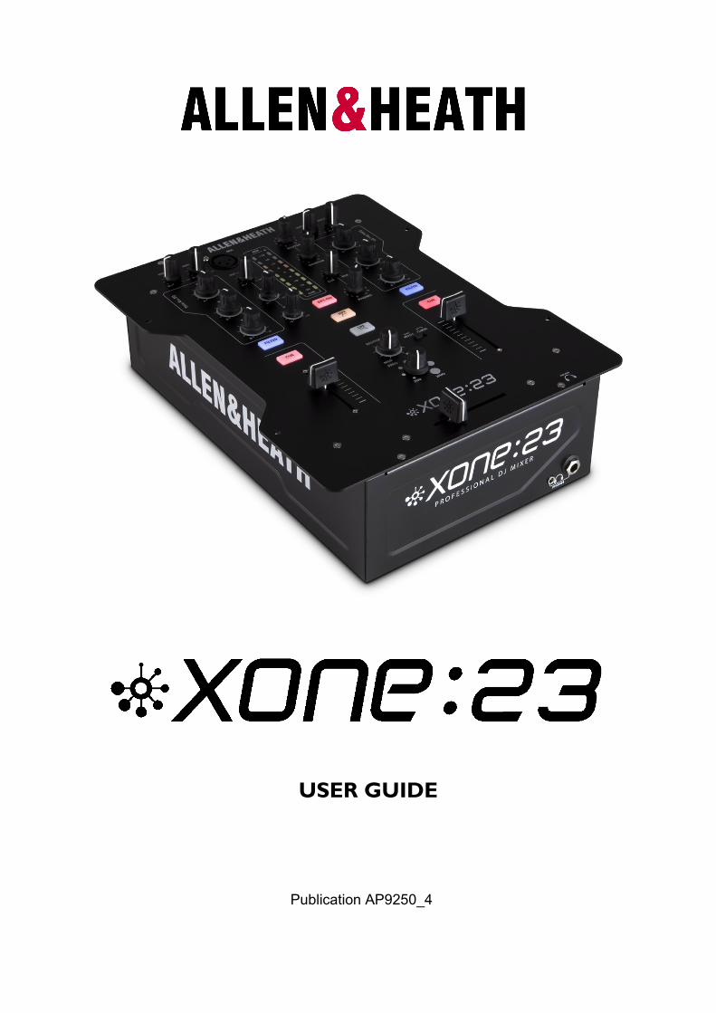
Input level controls
Adjust so that the aver-age music level lights the 0 LED on the meter with the beats lighting the +3 to +6 LED Turn down if the +10 Red LED is illu-minated Each input has its own separate level control so make sure to f u l l y t u r n d o w n (anticlockwise) the input you donrsquot want feeding into the mix
3-Band EQ
Turn anti-clockwise to cut a frequency band or clockwise to boost
Channel Fader
VCA fader allows you to progressively raise or lower the channel signal in the mix
For best signal-to-noise ratio mix with the fader at or near the top of its travel
FilterFX SND switch
Pressing this switch sends the channel signal to the VCF filter section and to the external effects SND output
Channel Cue switch
Pressing this switch allows you to monitor the channel signal with the fader fully down before bringing it into the mix
8
MASTER CONTROLS
Master output Level
Sets the signal level to the
main XLR mix output
Monitor output Level
Sets the signal level for the
local monitor (booth) output
Headphone level
Sets the level of the head-
phone output
Warning Very high level can
cause hearing damage
Crossfader curve switch
Push to the left for a progressive fader
response useful for blending between
tracks Push to the right for a sharper
response more suitable for scratching
CueMix Control
Turn left (Cue) to hear the
activated channel Cue
If no channel Cue is activated
the Mix output will be heard
Turn right (Mix) to hear the
Mix output
In the centre position the Cue
signal and the main mix are
summed together
Crossfader
This is used to ldquofaderdquo the signal level between
the two channels and its response is set us-
ing the curve switch When the crossfader is
fully over to the left only the music from
channel 1 will be heard and when fully to the
right only channel 2 When in the centre the
music from both channels will be heard in
equal proportion
Headphone Socket
Accepts both 14rdquo and 35mm
plugs Use a good quality set
with an impedance between 25
- 70 Ohms
9
MIC AND FILTER CONTROLS
Filter Resonance control
Changes the ldquoQrdquo or sharpness
of the VCF
Mild will give a smooth filter
sound Wild will make the
filter sound more pronounced
(sharper ldquoQrdquo)
Filter type select
HPF - allows signals above the
cut-off frequency to pass
LPF - allows signals below the
cut-off frequency to pass
FX loop on switch
Press this switch to activate
the external effect loop Leave
switched off if an external
effects unit is not connected
Filter Frequency
Sets the cut off frequency of
the VCF filter
Microphone EQ
2 band EQ for adjusting the
tonal balance of the DJ mic
Microphone input
Professional XLR balanced mic
input Use a low impedance
dynamic hypercardioid Mic for
best results
Microphone Level
Adjusts the signal level of the
mic input If you are not using
the mic turn to minimum to
prevent noise pick up
10
REAR PANEL CONNECTIONS
Phono inputs
For connection to turntables only this input has RIAA equalization for
moving magnet cartridges
Note An internal modification can convert these to Line (see page 14)
Effects SND output
Connect this output
to the input of an ex-
ternal effects unit
Line input
For connection to
a line level device
(CD players etc)
Line input
For connection to
a line level device
(CD players etc)
Effects RTN input
Connect this input to
the output of an
external effects unit
PSU connection
To prevent damage to your
Xone23 only use an AampH
approved power supply
Power Switch
Switches the unit OnOff
Main outputs
Connect these to a PA
amplifier using professional
balanced XLR connectors
for maximum hum and
noise rejection
Do not short either pins
2 or 3 to ground For
unbalanced operation
use pin 2 only and leave
pin 3 floating
Failure to observe this
could result in damage
to your Xone23
Monitor output
Connect to a powered
speaker or Hi-FI system
Record output
Use to record your mix
Connect to a Minidisk
recorder or computer
soundcard input etc
Grounding post
Connect the ground
wire from turntables
(if fitted) to minimise
hum
MADE IN CHINA
11
FILTER REFERENCE
The VCF Filters
A voltage controlled filter is an audio filter where the cut-off frequency is altered by a DC control voltage rather than a variable resistor This produces a much wider operating range and more control over the filter response to create unlimited combinations of tonal effect
Filter Type Select
The filters provide two simultaneous filter types high-pass and low-pass A large illuminated switch selects which type is active
The graphs below show the effect on the audio frequency response for the two filter types The range of sweep from low to high frequency is shown together with the effect of adjusting RESONANCE
The vertical scale shows the amount of cut or boost around the normal 0dB operating level The horizontal scale shows the change in frequency from low (bass) to high (treble)
10k20 1kHz100 20k
0dB
+5
+10
+15
+20
-5
-10
-15
-20
LO-PASS FILTER
LO HI
BAND-PASS FILTER
LO HI
10k20 1kHz100 20k
0dB
+5
+10
+15
+20
-5
-10
-15
-20
10k20 1kHz100 20k
0dB
+5
+10
+15
+20
-5
-10
-15
-20
HI-PASS FILTER
LO HI
10k20 1kHz100 20k
0dB
+5
+10
+15
+20
-5
-10
-15
-20
LO-PASS FILTER
LO HI
BAND-PASS FILTER
LO HI
10k20 1kHz100 20k
0dB
+5
+10
+15
+20
-5
-10
-15
-20
10k20 1kHz100 20k
0dB
+5
+10
+15
+20
-5
-10
-15
-20
HI-PASS FILTER
LO HI
12
It is most important that the system level settings are correctly set It is well known that many DJs push the level to maximum with meters peaking hard in the belief that they are getting the best from the system THIS IS NOT THE CASE The best can only be achieved if the system levels are set within the normal operating range and not allowed to peak Peaking simply results in signal distortion not more volume It is the specification of the amplifier speaker system that sets the maximum volume that can be achieved not the console The human ear too can fool the operator into believing that more volume is needed Be careful as this is in fact a warning that hearing damage will result if high listening levels are maintained Remember that it is the QUALITY of the sound that pleases the ear not just the VOLUME
OPERATING LEVELS
The diagram below illustrates the operating range of the audio signal
NORMAL OPERATING RANGE For normal music the signal should range between ndash6 and +6 on the meters with average around 0dB This allows enough HEADROOM for unexpected peaks before the signal hits its maximum CLIPPING voltage and distorts
It also achieves the best SIGNAL-TO-NOISE RATIO by keeping the signal well above the residual NOISE FLOOR (system hiss)
The DYNAMIC RANGE is the maximum signal swing available between the residual noise floor and clipping
An important note hellip
The human ear is a remarkable organ with the ability to com-press or lsquoshut downrsquo when sound levels become too high Do not interpret this natural response as a reason to turn the sys-tem volume up further As the session wears on ear fatigue may set in and the speaker cones may become hot increasing distortion and reducing the ability of listeners to gain any ben-efit from increased volume
13
The connection to earth (ground) in an audio system is important for two reasons
SAFETY - To protect the operator from high voltage electric shock and
AUDIO PERFORMANCE - To minimise the effect of earth (ground) loops which result in audible hum and buzz and to shield the audio signals from interference
For safety it is important that all equipment earths are connected to mains earth so that exposed metal parts are prevented from carrying high voltage which can injure or even kill the operator It is recommended that a qualified system engineer check the continuity of the safety earth from all points in the system including microphone bodies turntable chassis equipment cases and so on
The same earth is also used to shield audio cables from external interference such as the hum fields associated with power transformers lighting dimmer buzz and computer radiation Problems arise when the signal sees more than one path to mains earth An lsquoearth looprsquo (ground loop) results causing current to flow between the different earth paths This condition is usually detected as a mains frequency audible hum or buzz
To ensure safe and trouble-free operation we recommend the following
Have your mains system checked by a qualified electrician If the supply earthing is solid to start with you are less likely to experience problems
Make sure that turntables are correctly earthed A chassis earth terminal is provided on the console rear panel to connect to turntable earth straps
Use low impedance sources such as microphones and line level equipment rated at 200 ohms or less to reduce susceptibility to interference The console outputs are designed to operate at very low impedance to minimise interference problems
Use balanced connections for microphones and mix output as these provide further immunity by cancelling out interference that may be picked up on long cable runs
Do not unbalance the Xone23 XLR outputs by shorting pin 3 to ground as this may damage the circuitry for unbalanced operation connect the hot signal to pin 2 and the ground to pin 1 Leave pin 3 floating
Use good quality cables and connectors and check for correct wiring and reliable solder joints Allow sufficient cable loop to prevent damage through stretching
If you are not sure Contact your service agent or local Allen amp Heath dealer for advice
EARTHING
14
SERVICING
How to replace the crossfader
If the crossfader is subject to a lot of use it will in time wear out and need replacing Intermittent or noisy operation is
an indication that it is becoming worn Using a propriety fader cleaner such as CaigLube might temporarily restore use
but DO NOT use on a new fader as it will wash away the factory applied grease
Warning Dismantling your mixer could invalidate the warranty if you are unsure of your ability to safely carry out this
work then it is advised that you leave it to a qualified service technician
Tools you will need are T10 and T8 Torx screwdrivers Ensure that the power supply has been turned off and discon-
nected from the unit Using the T10 torxdriver remove the three screws located in the centre of the channel input and
FX loop connectors (see illustration) then using the T8 torxdriver remove the 8 screws that hold the front panel to the
chassis Now carefully lift the front edge of the panel up until the PCBs clear the chassis and pull the whole assembly
forward slightly until the connectors at the rear are free from the chassis You can now lift the front panel up to gain
sufficient access to replace the crossfader
If you wish to completely remove the front panel assembly you will need to unscrew the 14rdquo headphone bezel using an
11mm or 716 AF socket and remove the T10 screw that secures the headphone PCB to the chassis Carefully unplug
the multi-way harness from the connector PCB and lift the front panel away from the chassis
Reassembly is a reverse of this procedure Take great care to ensure that no harnesses become trapped and that all
connectors are fully pushed home Replace the screws and test the mixer for correct operation
REMOVE THE T10 SCREWS ARROWED
Unscrew headphone bezel and
remove T10 screw that secures the headphone PCB to the chassis
To Replace the crossfader
Using the T8 driver remove the 2 screws either
side of the crossfader and lower the crossfader
mounting plate - unplug the 4way harness from
the crossfader PCB and unscrew the fader from
the mounting plate
The mounting plate is designed to allow for fit-
ment of the contactless Innofader and can be
fitted in two different positions depending which
fader is being fitted
The standard fader can be ordered under AampH
part number 004-503JIT
The Innofader can be ordered under part num-
ber 004-504JIT
If the RIAA input level is too low or you wish to convert them to Line level
To increase the gain by 6dB remove the resistors arrowed and link the Pads with solder These resistors are located on the underside of the front panel PCB directly behind the Input RCA connectors
To convert to Line level remove the resistors and leave the Pads unsoldered
RIAA input options
15
REPLACEMENT PARTS USER-REPLACEABLE PARTS
AB8172 POT NUT BK (19 places -
under knobs)
AJ5320 XONE FADER KNOB
(3 places - faders)
AJ7304 XONE KNOB
(SML) (11 places)
AJ7305 XONE KNOB
(LGE) (8 places)
AB9256 25x9 AB TORX (10 places) on
front panel and rear chassis panel
The diagram above shows all of the replacement parts
When ordering please quote the part number(s) of the required parts
See the previous page for information on replacing the crossfader and for replacement cross-
fader assembly numbers
AB9037 M3 x 85 CSK (12 places)
16
No sound from mixer
Check that the unit is powered on and that an audio signal is connected to a channel input
Check that the Input level controls are turned clockwise at least to the centre position and that the music sources connected are in the correct inputs (Inputs 1 - 3 for turntables Inputs 2 - 4 for CD players)
Check that the EQ controls are in the centre position
Turn On the Channel CUE switch and raise the input channel LEVEL control until you see the meters displaying the music signal
Raise the channel fader and ensure that the crossfader is towards the channel that is receiving the audio signal
Turn up the MASTER MONITOR or HEADPHONE level controls depending on what output your amplifier is connected to or if you are monitoring through headphones
External effects unit canrsquot be heard
Check that the Effects unit is connected correctly (see page 5) and switched on - the SND on the rear panel of the mixer should be connected to the input socket on the external effects unit and the output from the effects unit should be connected to the RTN
Check that the EXT - ON switch is on (illuminated RED) and that the channel FILTER switch is ON (illuminated BLUE)
Signal is loud and distorted
Check that the audio source is connected to the correct input ie donrsquot connect a CD player to the PHONO input
Adjust the channel input LEVEL so that the meters peak the +3 or +6 LEDs If the red +10 meter LED comes on turn down the channel LEVEL control
FAULT FINDING
17
SPECIFICATIONS
Connections
Inputs
Connection Impedance Nominal Level Maximum Level
Phono RCA 47K330pF 7mV-100mV
Line RCA 20K ohm -10 to +20dBu
FX RTN RCA 10K ohm 0 to +20dBu
Mic XLR lt2K ohm -42 TO ndash12dBu
Outputs
Main Mix Balanced XLR 100 ohms +4dBu +28dBu
Monitor RCA 100 ohms -2dBu +22dBu
Record RCA 100 ohms -2dBu +19dBu
FX SND RCA 100 ohms -2dBu +19dBu
Headphones 35mm and
14rdquo TRS Jacks
1 ohm 200mW RMS into
30 ohms
Performance
Distortion Main Mix out +10dBu 001 THD+N
Noise 22-22Khz Main Mix out unity -85dBu un-weighted
Fader shut off Channel fader gt-80dB
Xfade shut off Xfader gt-80dB
Frequency
Response
10Hz to 50kHz +-0dB
Dimensions Weight 27kg (6lb)
Weight Packed 4kg (88lb)
18
BLOCK DIAGRAM
19
20
PRODUCT REGISTRATION
Registering your product
Please register your product with AllenampHeath online at
httpwwwallen-heathcomsupportregister-product
21

2
XONE23 User Guide AP9250 Issue 4
Copyright copy 2018 Allen amp Heath Limited All rights reserved
Allen amp Heath Limited
Kernick Industrial Estate Penryn Cornwall TR10 9LU UK
wwwallen-heathcom
Limited One Year Manufacturerrsquos Warranty
Allen amp Heath warrants the Allen amp Heath - branded hardware product and accessories contained in the original packaging (Allen amp Heath Productrdquo) against defects in materi-als and workmanship when used in accordance with Allen amp Heaths user manuals tech-nical specifications and other Allen amp Heath product published guidelines for a period of ONE (1) YEAR from the date of original purchase by the end-user purchaser (Warranty Period)
This warranty does not apply to any non-Allen amp Heath branded hardware products or any software even if packaged or sold with Allen amp Heath hardware Please refer to the licensing agreement accompanying the software for details of your rights with respect to the use of software (ldquoEULArdquo) Details of the EULA warranty policy and other useful information can be found on the Allen amp Heath website wwwallen-heathcomlegal
Repair or replacement under the terms of the warranty does not provide right to extension or renewal of the warranty period Repair or direct replacement of the product under the terms of this warranty may be fulfilled with functionally equivalent service exchange units
This warranty is not transferable This warranty does not cover fader wear and tear
This warranty will be the purchaserrsquos sole and exclusive remedy and neither Allen amp Heath nor its approved service centres shall be liable for any incidental or consequential damages or breach of any express or implied warranty of this product
Conditions of Warranty The equipment has not been subject to misuse either intended or accidental neglect or alteration other than as described in the User Guide or Service Manual or approved by Al-len amp Heath Any necessary adjustment alteration or repair has been carried out by an authorised Allen amp Heath distributor or agent The defective unit is to be returned carriage prepaid to the place of purchase an author-ised Allen amp Heath distributor or agent with proof of purchase Please discuss this with the distributor or the agent before shipping If the unit is to be repaired in a different country to that of its purchase the repair may take longer than normal whilst the warranty is con-firmed and parts are sourced Units returned should be packed in the original carton to avoid transit damage In certain territories the terms may vary Check with your Allen amp Heath distributor or agent for any additional warranty information which may apply If further assistance is required please contact Allen amp Heath Ltd
DISCLAIMER Allen amp Heath shall not be liable for the loss of any savedstored data in products that are either repaired or replaced
XONE23 complies with the European Electromagnetic Compatibility directives
201430EU and the European Low Voltage directives 201435EU
Any changes or modifications to the equipment not approved by Allen amp Heath could void the compliance of the product and therefore the users authority to operate it
3
PACKED ITEMS
Check that you have received the following
Safety Sheet
Important Read this sheet before starting
Retain for future reference
Power Supply
12V - 25 Amps
Xone23 mixer
Power supply IEC Lead
This is country specific and will vary with mains voltageterritory
4
CONTENTS
Congratulations on purchasing the Allen amp Heath Xone23 performance DJ mixer To ensure that you get the maximum benefit from the unit please spare a few minutes familiarizing yourself with the controls and setup procedures outlined in this user guide For further information please refer to the additional information available on our web site or contact our product support team
httpwwwallen-heathcom
Warranty 2
Packed Items 3
Contents 4
Connection diagram 5
Introduction 6
Input channel controls 7
Master section controls 8
Mic and Filter controls 9
Rear panel connections 10
Filters reference 11
Operating levels 12
Earthing 13
Servicing 14
User replaceable spare parts 15
Fault finding 16
Specification 17
Block Diagram 18
Product registration 20
5
APPLICATION DIAGRAM
6
INTRODUCTION TO THE XONE23
The Xone23 is a high performance 2+2 channel VCA mixer designed around the latest analogue circuitry featuring microprocessor control of all signal routing
It is equipped with a version of the famous Xone filter system 3 band EQ plus a sendreturn loop for external effects
The crossfader curve has two settings suitable for either blending or beat matching or a more aggressive curve for scratching For ultimate crossfader performance the mixer can also be equipped with a custom Innofader available from your nearest Allen amp Heath stockist (part number 004-504JIT)
With a studio standard 20dB of signal headroom a separate booth monitor and balanced XLR main outputs (with an impressive +28dBu max level) the Xone23 is perfect for the DJ who requires a high quality compact mix tool
Key features of the Xone23 are
bull 2+2 stereo channels with dual levels for phonoline inputs
bull Up to 4 sources can be mixed simultaneously
bull 3 Band equalizer
bull Voltage Controlled Filter system
bull SendReturn loop for external FX
bull Accurate signal level monitoring with peak hold
bull Main mix outputs on professional balanced XLR connectors
bull Dedicated local monitor (booth monitor)
bull Pro standard headroom (+20dB) to prevent overload
bull +28dBu maximum output level (balanced XLR)
bull Low audio distortion (typically 001 at +10dBu output)
bull Dedicated record output
bull Crossfader curve switch
bull Innofader crossfader option
bull Cue mix control with illuminated Cue switches
bull UV sensitive ink screen for improved low light legibility
bull Universal voltage power supply (works anywhere in the World)
We wish you the same fun playing on it as we have had designing it
7
INPUT CHANNEL CONTROLS
Input level controls
Adjust so that the aver-age music level lights the 0 LED on the meter with the beats lighting the +3 to +6 LED Turn down if the +10 Red LED is illu-minated Each input has its own separate level control so make sure to f u l l y t u r n d o w n (anticlockwise) the input you donrsquot want feeding into the mix
3-Band EQ
Turn anti-clockwise to cut a frequency band or clockwise to boost
Channel Fader
VCA fader allows you to progressively raise or lower the channel signal in the mix
For best signal-to-noise ratio mix with the fader at or near the top of its travel
FilterFX SND switch
Pressing this switch sends the channel signal to the VCF filter section and to the external effects SND output
Channel Cue switch
Pressing this switch allows you to monitor the channel signal with the fader fully down before bringing it into the mix
8
MASTER CONTROLS
Master output Level
Sets the signal level to the
main XLR mix output
Monitor output Level
Sets the signal level for the
local monitor (booth) output
Headphone level
Sets the level of the head-
phone output
Warning Very high level can
cause hearing damage
Crossfader curve switch
Push to the left for a progressive fader
response useful for blending between
tracks Push to the right for a sharper
response more suitable for scratching
CueMix Control
Turn left (Cue) to hear the
activated channel Cue
If no channel Cue is activated
the Mix output will be heard
Turn right (Mix) to hear the
Mix output
In the centre position the Cue
signal and the main mix are
summed together
Crossfader
This is used to ldquofaderdquo the signal level between
the two channels and its response is set us-
ing the curve switch When the crossfader is
fully over to the left only the music from
channel 1 will be heard and when fully to the
right only channel 2 When in the centre the
music from both channels will be heard in
equal proportion
Headphone Socket
Accepts both 14rdquo and 35mm
plugs Use a good quality set
with an impedance between 25
- 70 Ohms
9
MIC AND FILTER CONTROLS
Filter Resonance control
Changes the ldquoQrdquo or sharpness
of the VCF
Mild will give a smooth filter
sound Wild will make the
filter sound more pronounced
(sharper ldquoQrdquo)
Filter type select
HPF - allows signals above the
cut-off frequency to pass
LPF - allows signals below the
cut-off frequency to pass
FX loop on switch
Press this switch to activate
the external effect loop Leave
switched off if an external
effects unit is not connected
Filter Frequency
Sets the cut off frequency of
the VCF filter
Microphone EQ
2 band EQ for adjusting the
tonal balance of the DJ mic
Microphone input
Professional XLR balanced mic
input Use a low impedance
dynamic hypercardioid Mic for
best results
Microphone Level
Adjusts the signal level of the
mic input If you are not using
the mic turn to minimum to
prevent noise pick up
10
REAR PANEL CONNECTIONS
Phono inputs
For connection to turntables only this input has RIAA equalization for
moving magnet cartridges
Note An internal modification can convert these to Line (see page 14)
Effects SND output
Connect this output
to the input of an ex-
ternal effects unit
Line input
For connection to
a line level device
(CD players etc)
Line input
For connection to
a line level device
(CD players etc)
Effects RTN input
Connect this input to
the output of an
external effects unit
PSU connection
To prevent damage to your
Xone23 only use an AampH
approved power supply
Power Switch
Switches the unit OnOff
Main outputs
Connect these to a PA
amplifier using professional
balanced XLR connectors
for maximum hum and
noise rejection
Do not short either pins
2 or 3 to ground For
unbalanced operation
use pin 2 only and leave
pin 3 floating
Failure to observe this
could result in damage
to your Xone23
Monitor output
Connect to a powered
speaker or Hi-FI system
Record output
Use to record your mix
Connect to a Minidisk
recorder or computer
soundcard input etc
Grounding post
Connect the ground
wire from turntables
(if fitted) to minimise
hum
MADE IN CHINA
11
FILTER REFERENCE
The VCF Filters
A voltage controlled filter is an audio filter where the cut-off frequency is altered by a DC control voltage rather than a variable resistor This produces a much wider operating range and more control over the filter response to create unlimited combinations of tonal effect
Filter Type Select
The filters provide two simultaneous filter types high-pass and low-pass A large illuminated switch selects which type is active
The graphs below show the effect on the audio frequency response for the two filter types The range of sweep from low to high frequency is shown together with the effect of adjusting RESONANCE
The vertical scale shows the amount of cut or boost around the normal 0dB operating level The horizontal scale shows the change in frequency from low (bass) to high (treble)
10k20 1kHz100 20k
0dB
+5
+10
+15
+20
-5
-10
-15
-20
LO-PASS FILTER
LO HI
BAND-PASS FILTER
LO HI
10k20 1kHz100 20k
0dB
+5
+10
+15
+20
-5
-10
-15
-20
10k20 1kHz100 20k
0dB
+5
+10
+15
+20
-5
-10
-15
-20
HI-PASS FILTER
LO HI
10k20 1kHz100 20k
0dB
+5
+10
+15
+20
-5
-10
-15
-20
LO-PASS FILTER
LO HI
BAND-PASS FILTER
LO HI
10k20 1kHz100 20k
0dB
+5
+10
+15
+20
-5
-10
-15
-20
10k20 1kHz100 20k
0dB
+5
+10
+15
+20
-5
-10
-15
-20
HI-PASS FILTER
LO HI
12
It is most important that the system level settings are correctly set It is well known that many DJs push the level to maximum with meters peaking hard in the belief that they are getting the best from the system THIS IS NOT THE CASE The best can only be achieved if the system levels are set within the normal operating range and not allowed to peak Peaking simply results in signal distortion not more volume It is the specification of the amplifier speaker system that sets the maximum volume that can be achieved not the console The human ear too can fool the operator into believing that more volume is needed Be careful as this is in fact a warning that hearing damage will result if high listening levels are maintained Remember that it is the QUALITY of the sound that pleases the ear not just the VOLUME
OPERATING LEVELS
The diagram below illustrates the operating range of the audio signal
NORMAL OPERATING RANGE For normal music the signal should range between ndash6 and +6 on the meters with average around 0dB This allows enough HEADROOM for unexpected peaks before the signal hits its maximum CLIPPING voltage and distorts
It also achieves the best SIGNAL-TO-NOISE RATIO by keeping the signal well above the residual NOISE FLOOR (system hiss)
The DYNAMIC RANGE is the maximum signal swing available between the residual noise floor and clipping
An important note hellip
The human ear is a remarkable organ with the ability to com-press or lsquoshut downrsquo when sound levels become too high Do not interpret this natural response as a reason to turn the sys-tem volume up further As the session wears on ear fatigue may set in and the speaker cones may become hot increasing distortion and reducing the ability of listeners to gain any ben-efit from increased volume
13
The connection to earth (ground) in an audio system is important for two reasons
SAFETY - To protect the operator from high voltage electric shock and
AUDIO PERFORMANCE - To minimise the effect of earth (ground) loops which result in audible hum and buzz and to shield the audio signals from interference
For safety it is important that all equipment earths are connected to mains earth so that exposed metal parts are prevented from carrying high voltage which can injure or even kill the operator It is recommended that a qualified system engineer check the continuity of the safety earth from all points in the system including microphone bodies turntable chassis equipment cases and so on
The same earth is also used to shield audio cables from external interference such as the hum fields associated with power transformers lighting dimmer buzz and computer radiation Problems arise when the signal sees more than one path to mains earth An lsquoearth looprsquo (ground loop) results causing current to flow between the different earth paths This condition is usually detected as a mains frequency audible hum or buzz
To ensure safe and trouble-free operation we recommend the following
Have your mains system checked by a qualified electrician If the supply earthing is solid to start with you are less likely to experience problems
Make sure that turntables are correctly earthed A chassis earth terminal is provided on the console rear panel to connect to turntable earth straps
Use low impedance sources such as microphones and line level equipment rated at 200 ohms or less to reduce susceptibility to interference The console outputs are designed to operate at very low impedance to minimise interference problems
Use balanced connections for microphones and mix output as these provide further immunity by cancelling out interference that may be picked up on long cable runs
Do not unbalance the Xone23 XLR outputs by shorting pin 3 to ground as this may damage the circuitry for unbalanced operation connect the hot signal to pin 2 and the ground to pin 1 Leave pin 3 floating
Use good quality cables and connectors and check for correct wiring and reliable solder joints Allow sufficient cable loop to prevent damage through stretching
If you are not sure Contact your service agent or local Allen amp Heath dealer for advice
EARTHING
14
SERVICING
How to replace the crossfader
If the crossfader is subject to a lot of use it will in time wear out and need replacing Intermittent or noisy operation is
an indication that it is becoming worn Using a propriety fader cleaner such as CaigLube might temporarily restore use
but DO NOT use on a new fader as it will wash away the factory applied grease
Warning Dismantling your mixer could invalidate the warranty if you are unsure of your ability to safely carry out this
work then it is advised that you leave it to a qualified service technician
Tools you will need are T10 and T8 Torx screwdrivers Ensure that the power supply has been turned off and discon-
nected from the unit Using the T10 torxdriver remove the three screws located in the centre of the channel input and
FX loop connectors (see illustration) then using the T8 torxdriver remove the 8 screws that hold the front panel to the
chassis Now carefully lift the front edge of the panel up until the PCBs clear the chassis and pull the whole assembly
forward slightly until the connectors at the rear are free from the chassis You can now lift the front panel up to gain
sufficient access to replace the crossfader
If you wish to completely remove the front panel assembly you will need to unscrew the 14rdquo headphone bezel using an
11mm or 716 AF socket and remove the T10 screw that secures the headphone PCB to the chassis Carefully unplug
the multi-way harness from the connector PCB and lift the front panel away from the chassis
Reassembly is a reverse of this procedure Take great care to ensure that no harnesses become trapped and that all
connectors are fully pushed home Replace the screws and test the mixer for correct operation
REMOVE THE T10 SCREWS ARROWED
Unscrew headphone bezel and
remove T10 screw that secures the headphone PCB to the chassis
To Replace the crossfader
Using the T8 driver remove the 2 screws either
side of the crossfader and lower the crossfader
mounting plate - unplug the 4way harness from
the crossfader PCB and unscrew the fader from
the mounting plate
The mounting plate is designed to allow for fit-
ment of the contactless Innofader and can be
fitted in two different positions depending which
fader is being fitted
The standard fader can be ordered under AampH
part number 004-503JIT
The Innofader can be ordered under part num-
ber 004-504JIT
If the RIAA input level is too low or you wish to convert them to Line level
To increase the gain by 6dB remove the resistors arrowed and link the Pads with solder These resistors are located on the underside of the front panel PCB directly behind the Input RCA connectors
To convert to Line level remove the resistors and leave the Pads unsoldered
RIAA input options
15
REPLACEMENT PARTS USER-REPLACEABLE PARTS
AB8172 POT NUT BK (19 places -
under knobs)
AJ5320 XONE FADER KNOB
(3 places - faders)
AJ7304 XONE KNOB
(SML) (11 places)
AJ7305 XONE KNOB
(LGE) (8 places)
AB9256 25x9 AB TORX (10 places) on
front panel and rear chassis panel
The diagram above shows all of the replacement parts
When ordering please quote the part number(s) of the required parts
See the previous page for information on replacing the crossfader and for replacement cross-
fader assembly numbers
AB9037 M3 x 85 CSK (12 places)
16
No sound from mixer
Check that the unit is powered on and that an audio signal is connected to a channel input
Check that the Input level controls are turned clockwise at least to the centre position and that the music sources connected are in the correct inputs (Inputs 1 - 3 for turntables Inputs 2 - 4 for CD players)
Check that the EQ controls are in the centre position
Turn On the Channel CUE switch and raise the input channel LEVEL control until you see the meters displaying the music signal
Raise the channel fader and ensure that the crossfader is towards the channel that is receiving the audio signal
Turn up the MASTER MONITOR or HEADPHONE level controls depending on what output your amplifier is connected to or if you are monitoring through headphones
External effects unit canrsquot be heard
Check that the Effects unit is connected correctly (see page 5) and switched on - the SND on the rear panel of the mixer should be connected to the input socket on the external effects unit and the output from the effects unit should be connected to the RTN
Check that the EXT - ON switch is on (illuminated RED) and that the channel FILTER switch is ON (illuminated BLUE)
Signal is loud and distorted
Check that the audio source is connected to the correct input ie donrsquot connect a CD player to the PHONO input
Adjust the channel input LEVEL so that the meters peak the +3 or +6 LEDs If the red +10 meter LED comes on turn down the channel LEVEL control
FAULT FINDING
17
SPECIFICATIONS
Connections
Inputs
Connection Impedance Nominal Level Maximum Level
Phono RCA 47K330pF 7mV-100mV
Line RCA 20K ohm -10 to +20dBu
FX RTN RCA 10K ohm 0 to +20dBu
Mic XLR lt2K ohm -42 TO ndash12dBu
Outputs
Main Mix Balanced XLR 100 ohms +4dBu +28dBu
Monitor RCA 100 ohms -2dBu +22dBu
Record RCA 100 ohms -2dBu +19dBu
FX SND RCA 100 ohms -2dBu +19dBu
Headphones 35mm and
14rdquo TRS Jacks
1 ohm 200mW RMS into
30 ohms
Performance
Distortion Main Mix out +10dBu 001 THD+N
Noise 22-22Khz Main Mix out unity -85dBu un-weighted
Fader shut off Channel fader gt-80dB
Xfade shut off Xfader gt-80dB
Frequency
Response
10Hz to 50kHz +-0dB
Dimensions Weight 27kg (6lb)
Weight Packed 4kg (88lb)
18
BLOCK DIAGRAM
19
20
PRODUCT REGISTRATION
Registering your product
Please register your product with AllenampHeath online at
httpwwwallen-heathcomsupportregister-product
21
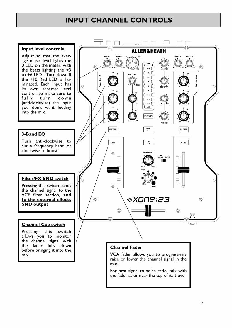
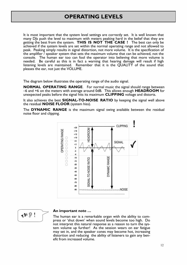
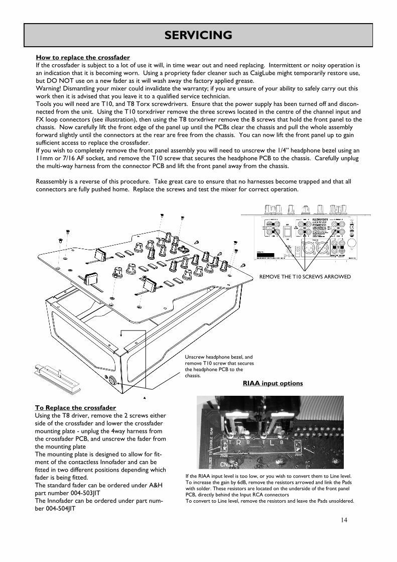

18
BLOCK DIAGRAM
19
20
PRODUCT REGISTRATION
Registering your product
Please register your product with AllenampHeath online at
httpwwwallen-heathcomsupportregister-product
21

19
20
PRODUCT REGISTRATION
Registering your product
Please register your product with AllenampHeath online at
httpwwwallen-heathcomsupportregister-product
21

20
PRODUCT REGISTRATION
Registering your product
Please register your product with AllenampHeath online at
httpwwwallen-heathcomsupportregister-product
21

21