Embed Size (px)
Citation preview
- 1 -
User Guide
EVGA X99 Classified
Specs and Initial Installation
(Part 1)
- 2 -
Table of Contents Before you Begin………………………………………………………………………3 Parts Not in the kit…………………………………………………………………….4 Intentions of the kit……………………………………………………………………4 Motherboard Specifications……………………………………………………………5 Unpacking and Parts Descriptions……………………………………………………..7 Equipment……………………………………………………………………………..7 Hardware Installation…………………………………………………………………..8 Component legend………..……………………………………………………………8 PCI-E Slot Breakdown………………………………………………………………....9 Rear I/O Panel legend………………………………………………………………..10 Preparing the Motherboard…………………………………………………………...11 Installing the CPU…………………………………………………………………….11 Installing the Cooling Device……………………………………….…………...…….12 Installing System Memory (DIMMs)……………...………………….......…..………...13 Compliance Information……………………………………………………………...14

- 3 -
Before You Begin…
EVGA welcomes you to the next generation of ground breaking performance, the X99 Classified. The X99 platform redefines high performance with the introduction of the first ever quad channel DDR4 architecture fueled by Intel’s Haswell-E/Broadwell-E CPU family for up to 128GB’s of RAM running at a maximum memory speed up to 3000MHz+ (OC), possible due to the 4 layer memory T-Routing design. Dual 8pin power provides up to 600 watts to the CPU for ample headroom for the most aggressive overclocks, and an Advanced 10 phase Digital VRM (IR3563B+IR3350) and a CPU socket with 150% higher Gold content, all rested on a 8 layer Hybrid Black PCB to provide industry leading stability for all your applications. Also, the board is not ONLY for peak overclocking, it is also fully featured to support any/all peripherals and functions available, Creative Core-3D audio, 4 way SLI support without the need for PLX chips, Type2 M.2 for WLAN, Type3 M.2 for SSD modules, 2 Intel Gigabit LAN, Intel AIC with Thunderbolt support, right angle power connectors, PCI-E disable switches and much more! Lastly, a motherboard is only as good as its BIOS, and we have revamped our GUI BIOS with a focus on overclocking, functionality, in a lean, straight forward package. And you should expect nothing less from a modern enthusiast BIOS.
With the features above and many more, EVGA is going to redefine motherboard performance.
- 4 -
Parts NOT in the Kit
This kit contains all the hardware necessary to install and connect your new EVGA X99 Classified Motherboard. However, it does NOT contain the following items that must be purchased separately in order to make the system fully functional and install an Operating System:
� Intel Socket 2011-3 Processor
� DDR4 System Memory
� CPU Cooling Device
� PCI Express Graphics Card
� Power Supply
� Hard Drive or SSD
� Keyboard / Mouse
� Monitor
� (Optional) Optical Drive
EVGA assumes you have purchased all the necessary parts needed to allow for proper system functionality. For a full list of supported CPUs on this motherboard, please visit www.evga.com/support/motherboard
Intentions of the Kit
This kit provides you with the motherboard and all connecting cables necessary to install the motherboard into a PC case.
When replacing a motherboard in a PC case, you will need to reinstall an operating system even though the current storage drive may already have one installed.
- 5 -
Motherboard
Motherboard Specifications
� Size:
EATX form factor of 12 inches x 10.375 inches (305x264mm)
� Microprocessor support: Intel Socket 2011-3 Processor
� Operating Systems: Supports Windows 8 / 7
� Contains Intel X99 chipset
� System Memory support: Supports Quad channel DDR4 up to 3000MHz+ (OC). Supports up to 128GB of DDR4 memory.
� USB 2.0 Ports:
8x from Intel X99 PCH – 6x external, 2x internal
Supports hot plug
Supports wake-up from S1 and S3 mode
Supports USB 2.0 protocol up to a 480 Mbps transmission rate
� USB 3.0 Ports:
6x from Intel X99 PCH – 4x external, 2x internal
Supports transfer speeds up to 5Gbps
Backwards compatible USB 2.0 and USB 1.1 support
� SATA Ports: Intel X99 PCH Controller 6x SATA 3/6G (600 MB/s) data transfer rate - Support for RAID 0, RAID 1, RAID 5, AND RAID 10 - Supports hot plug 4x SATA3/6G AHCI Only
� Onboard LAN:
1x Intel i217 Gigabit Ethernet PHY
1x Intel i210 Gigabit Ethernet MAC
Supports 10/100/1000 Mb/sec Ethernet

- 6 -
Ethernet Teaming Supported
� Onboard Audio:
Creative Core3D Quad-Core Audio Processor (CA0132)
Supports 6-channel (5.1) audio
Supports Optical Output
� PCI-E 3.0 Support:
Low power consumption and power management features
� Power Functions:
Supports ACPI (Advanced Configuration and Power Interface)
Supports S0 (normal), S1 (power on suspend), S3 (suspend to RAM), S4 (Suspend to disk - depends on OS), and S5 (soft - off)
� Expansion Slots:
5x PCI-E 16x slot 2x16/8, 3x8, 4x8
1x PCI-E 4x slot
2x M.2 Ports
-M.2 Socket 1 (Slot E) shares signal distribution from USB2.0 #3 port, please select the operational mode in BIOS setup menu
-M.2 Socket 2 (Slot M) shares signal distribution from PE5, please select the operational mode in BIOS setup menu
- 7 -
Unpacking and Parts Descriptions
Equipment
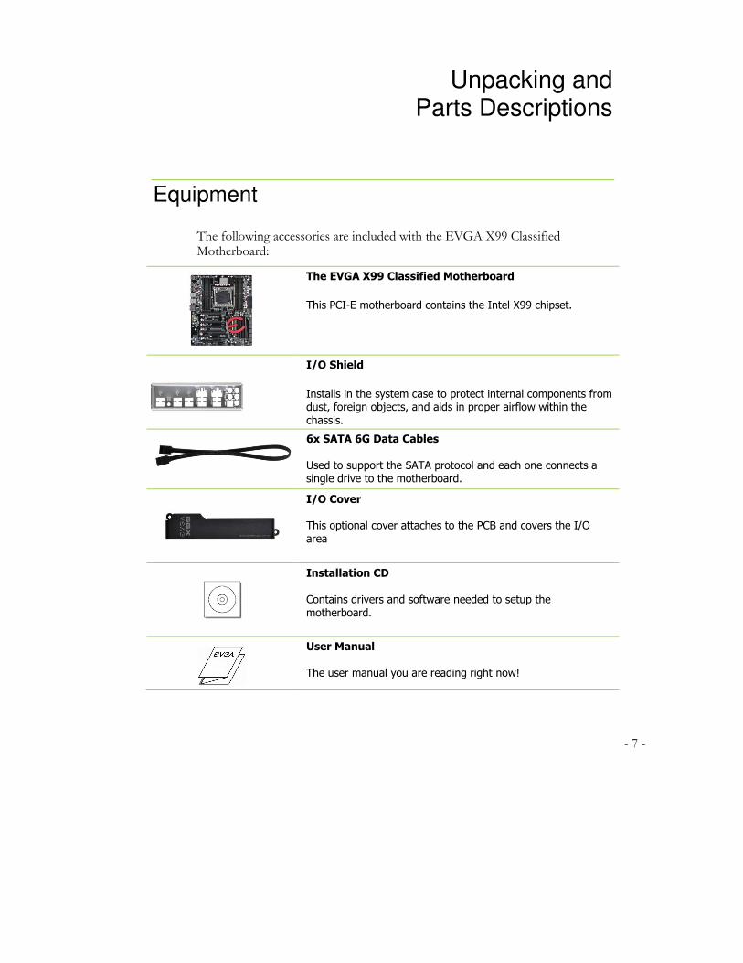
The following accessories are included with the EVGA X99 Classified Motherboard:
The EVGA X99 Classified Motherboard
This PCI-E motherboard contains the Intel X99 chipset.
I/O Shield
Installs in the system case to protect internal components from dust, foreign objects, and aids in proper airflow within the
chassis.
6x SATA 6G Data Cables
Used to support the SATA protocol and each one connects a single drive to the motherboard.
I/O Cover This optional cover attaches to the PCB and covers the I/O
area
Installation CD
Contains drivers and software needed to setup the
motherboard.
User Manual
The user manual you are reading right now!

- 8 -
Intel X99 Classified Motherboard
The EVGA X99 Classified Motherboard with the Intel X99 and PCH Chipset. Figure 1 shows the motherboard and Figure 2 shows the back panel connectors
FIGURE 1. X99 Classified Motherboard Layout
- 9 -
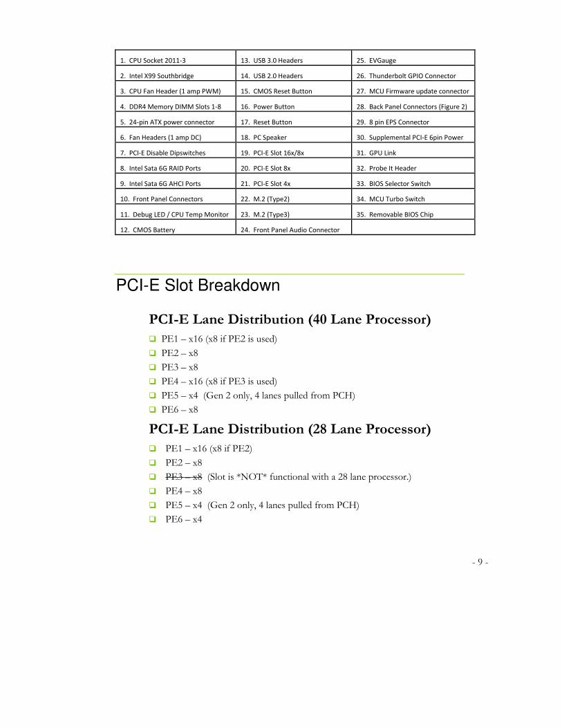
1. CPU Socket 2011-3 13. USB 3.0 Headers 25. EVGauge
2. Intel X99 Southbridge 14. USB 2.0 Headers 26. Thunderbolt GPIO Connector
3. CPU Fan Header (1 amp PWM) 15. CMOS Reset Button 27. MCU Firmware update connector
4. DDR4 Memory DIMM Slots 1-8 16. Power Button 28. Back Panel Connectors (Figure 2)
5. 24-pin ATX power connector 17. Reset Button 29. 8 pin EPS Connector
6. Fan Headers (1 amp DC) 18. PC Speaker 30. Supplemental PCI-E 6pin Power
7. PCI-E Disable Dipswitches 19. PCI-E Slot 16x/8x 31. GPU Link
8. Intel Sata 6G RAID Ports 20. PCI-E Slot 8x 32. Probe It Header
9. Intel Sata 6G AHCI Ports 21. PCI-E Slot 4x 33. BIOS Selector Switch
10. Front Panel Connectors 22. M.2 (Type2) 34. MCU Turbo Switch
11. Debug LED / CPU Temp Monitor 23. M.2 (Type3) 35. Removable BIOS Chip
12. CMOS Battery 24. Front Panel Audio Connector
PCI-E Slot Breakdown
PCI-E Lane Distribution (40 Lane Processor)
� PE1 – x16 (x8 if PE2 is used)
� PE2 – x8
� PE3 – x8
� PE4 – x16 (x8 if PE3 is used)
� PE5 – x4 (Gen 2 only, 4 lanes pulled from PCH)
� PE6 – x8
PCI-E Lane Distribution (28 Lane Processor)
� PE1 – x16 (x8 if PE2)
� PE2 – x8
� PE3 – x8 (Slot is *NOT* functional with a 28 lane processor.)
� PE4 – x8
� PE5 – x4 (Gen 2 only, 4 lanes pulled from PCH)
� PE6 – x4
- 10 -
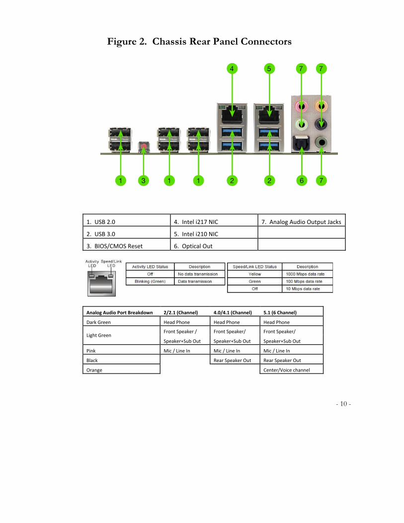
Figure 2. Chassis Rear Panel Connectors
1. USB 2.0 4. Intel i217 NIC 7. Analog Audio Output Jacks
2. USB 3.0 5. Intel i210 NIC
3. BIOS/CMOS Reset 6. Optical Out
Analog Audio Port Breakdown 2/2.1 (Channel) 4.0/4.1 (Channel) 5.1 (6 Channel)
Dark Green Head Phone Head Phone Head Phone
Light Green Front Speaker / Front Speaker/ Front Speaker/
Speaker+Sub Out Speaker+Sub Out Speaker+Sub Out
Pink Mic / Line In Mic / Line In Mic / Line In
Black
Rear Speaker Out Rear Speaker Out
Orange
Center/Voice channel
- 11 -
Preparing the Motherboard
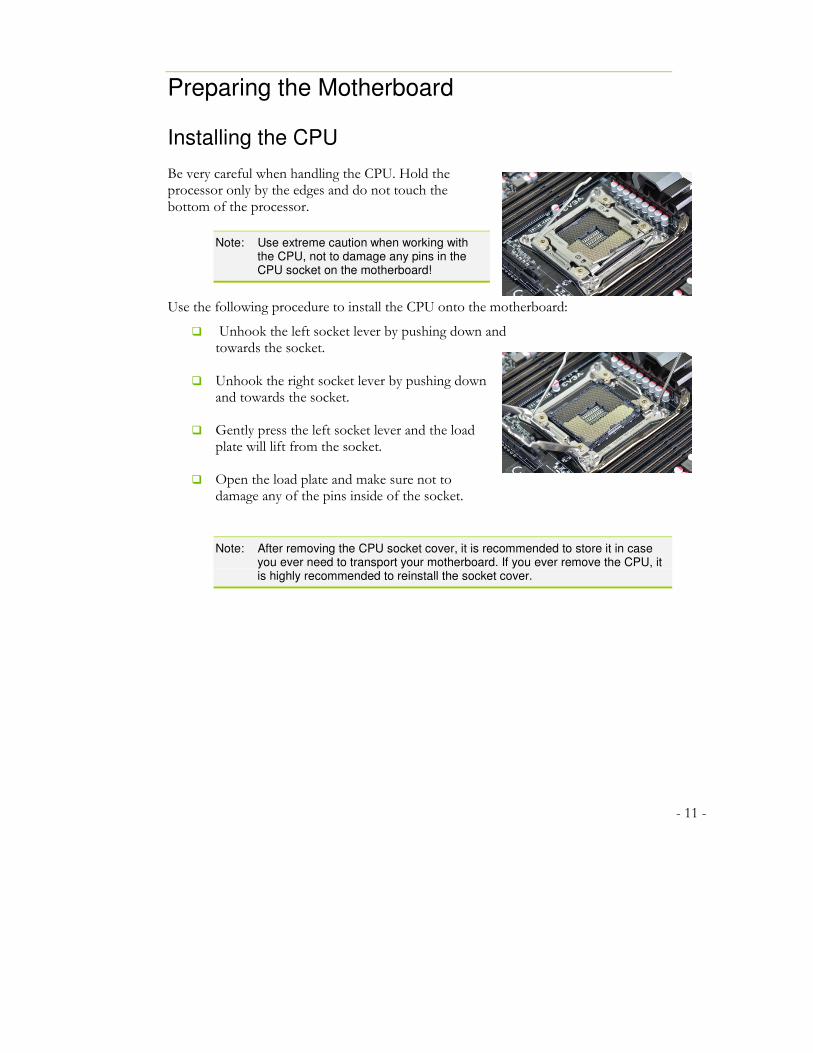
Installing the CPU
Be very careful when handling the CPU. Hold the processor only by the edges and do not touch the bottom of the processor.
Note: Use extreme caution when working with the CPU, not to damage any pins in the CPU socket on the motherboard!
Use the following procedure to install the CPU onto the motherboard:
� Unhook the left socket lever by pushing down and towards the socket.
� Unhook the right socket lever by pushing down and towards the socket.
� Gently press the left socket lever and the load
plate will lift from the socket.
� Open the load plate and make sure not to damage any of the pins inside of the socket.
Note: After removing the CPU socket cover, it is recommended to store it in case you ever need to transport your motherboard. If you ever remove the CPU, it is highly recommended to reinstall the socket cover.

- 12 -
� Align the notches on the CPU to the notches in the socket.
� Lower the processor straight down into the socket.
Note: Make sure the CPU is fully seated and level in the socket.
� Lower the load plate so it is resting on the CPU.
� Press the right socket lever down to lock into
place.
� Carefully lock the left lever back into place.
Installing the CPU Cooling Device
There are many different cooling devices that can be used with this motherboard. Follow the instructions that come with your cooling assembly.
- 13 -
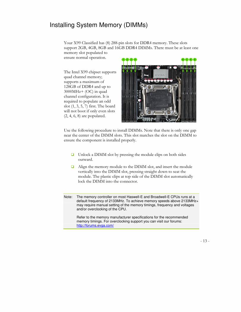
Installing System Memory (DIMMs)
Your X99 Classified has (8) 288-pin slots for DDR4 memory. These slots support 2GB, 4GB, 8GB and 16GB DDR4 DIMMs. There must be at least one memory slot populated to ensure normal operation.
The Intel X99 chipset supports quad channel memory; supports a maximum of 128GB of DDR4 and up to 3000MHz+ (OC) in quad channel configuration. It is required to populate an odd slot (1, 3, 5, 7) first. The board will not boot if only even slots (2, 4, 6, 8) are populated.
Use the following procedure to install DIMMs. Note that there is only one gap near the center of the DIMM slots. This slot matches the slot on the DIMM to ensure the component is installed properly.
� Unlock a DIMM slot by pressing the module clips on both sides outward.
� Align the memory module to the DIMM slot, and insert the module vertically into the DIMM slot, pressing straight down to seat the module. The plastic clips at top side of the DIMM slot automatically lock the DIMM into the connector.
Note: The memory controller on most Haswell-E and Broadwell-E CPUs runs at a default frequency of 2133MHz. To achieve memory speeds above 2133MHz+ may require manual setting of the memory timings, frequency and voltages and/or overclocking of the CPU.
Refer to the memory manufacturer specifications for the recommended
memory timings. For overclocking support you can visit our forums: http://forums.evga.com/
- 14 -
Compliance Information
FCC Compliance Information
This device complies with FCC Rules Part 15. Operation is subject to the following two conditions: (1) This device may not cause harmful interference, and (2) this device must accept any interference received, including interference that may cause undesired operation. This equipment has been tested and found to comply with the limits for a Class B digital device, pursuant to Part 15 of the FCC Rules. These limits are designed to provide reasonable protection against harmful interference in a residential installation. This equipment generates, uses and can radiate radio frequency energy and, if not installed and used in accordance with the manufacturer’s instructions, may cause harmful interference to radio communications. However, there is no guarantee that interference will not occur in a particular installation. If this equipment does cause harmful interference to radio or television reception, which can be determined by turning the equipment off and on, the user is encouraged to try to correct the interference by one or more of the following measures: (1) Increase the separation between the equipment and signal source, or (2) connect the equipment to an outlet on a circuit different from that to which the signal source is connected. Consult the dealer or an experienced computer technician for help. The use of shielded cables for connection of peripheral devices to the PC systems is required to ensure compliance with FCC regulations. Changes or modifications to this unit not expressly approved by the party responsible for compliance could void the user’s authority to operate the equipment.
CE Compliance Information
Generic Radiation Interference Standard for Information Technology Equipment. (EN 55022: 2006, Class B), (EN 61000-3-2: 2006), (EN 61000-3-3: 1995 + A1: 2001 + A2: 2005). Warning: This is a Class B product. In a domestic environment this product may cause radio interference in which case the user may be required to take adequate measure. Generic Immunity Standard for Information Technology Equipment. (EN 55024: 1998 + A1: 2001 + A2: 2003).
Trademark & Copyright Information
2001-2014 EVGA Corp. EVGA, the EVGA logo and combinations thereof are trademarks of EVGA Corp. All brand names, company names, service marks, logos, and trademarks of the company, or its affiliates or licensors are trademarks or registered trademarks of the company or its subsidiaries, affiliates or licensors in the US and other countries. Other company, products and service names may be trademarks or service marks of others. EVGA reserves the right to terminate this license if there is a violation of its terms or default by the Original Purchaser. Upon termination, for any reason, all copies of Software and materials must be immediately returned to EVGA and the Original Purchaser shall be liable to EVGA.com CORP for any and all damages suffered as a result of the violation or default.
Legal Information
All material including but not limited to, text, data, design specifications, diagnostics, graphics, logos, reference boards, files, images, drawings, and software including this document and the software itself (together and separately) is owned, controlled by, licensed to, or used with permission by EVGA Corporation and is protected by copyright, trademark, and other intellectual property rights. All is being provided “as is”, EVGA Corporation makes no warranties, whether express or implied, statutory or otherwise with respect to the materials and expressly disclaims all implied warranties of non-infringement, merchantability, and fitness for a particular purpose. In no event shall the liability of EVGA Corporation for claims arising from the use of the materials by anyone exceed the original purchase price of the materials (or replacement of the materials at EVGA Corporation’s option). All information furnished is believed to be accurate and reliable. However, EVGA Corporation assumes no responsibility for the consequences of use of such information or for any infringement of patents or other rights of third parties that may result from its use, or use of the Software. No license is granted by implication or otherwise under any patent or patent rights of EVGA Corporation except as expressly provided herein. All specifications mentioned in this publication are subject to change without notice.
Ver. 2