Embed Size (px)
Citation preview
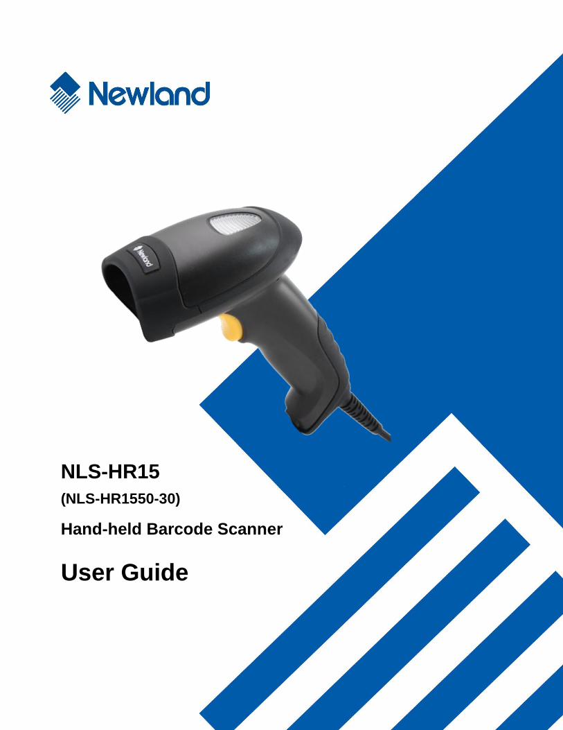
NLS-HR15
(NLS-HR1550-30)
Hand-held Barcode Scanner
User Guide
Disclaimer
© 2013 Fujian Newland Auto-ID Tech. Co., Ltd. All rights reserved.
Please read through the manual carefully before using the product and operate it according to the manual. It is advised that you
should keep this manual for future reference.
Do not disassemble the device or remove the seal label from the device. Otherwise, Fujian Newland Auto-ID Tech. Co., Ltd.
does not assume responsibility for the warranty or replacement.
All pictures in this manual are for reference only and actual product may differ. Regarding to the product modification and
update, Fujian Newland Auto-ID Tech. Co., Ltd. reserves the right to make changes to any software or product to improve
reliability, function, or design at any time without notice. Besides, the information contained herein is subject to change without
prior notice.
The products depicted in this manual may include software copyrighted by Fujian Newland Auto-ID Tech. Co., Ltd or a third
party. The user, corporation or individual, shall not duplicate, in whole or in part, distribute, modify, decompile, disassemble,
decode, reverse engineer, rent, transfer or sublicense such software without prior written consent from the copyright holders.
This manual is copyrighted. No part of this publication may be reproduced, distributed or used in any form without written
permission from Newland.
Fujian Newland Auto-ID Tech. Co., Ltd. reserves the right to make final interpretation of the statement above.
Fujian Newland Auto-ID Tech. Co., Ltd.
3F, Building A, No.1, Rujiang Xi Rd., Mawei, Fuzhou, Fujian, P.R. China. 350015.
http://www.nlscan.com
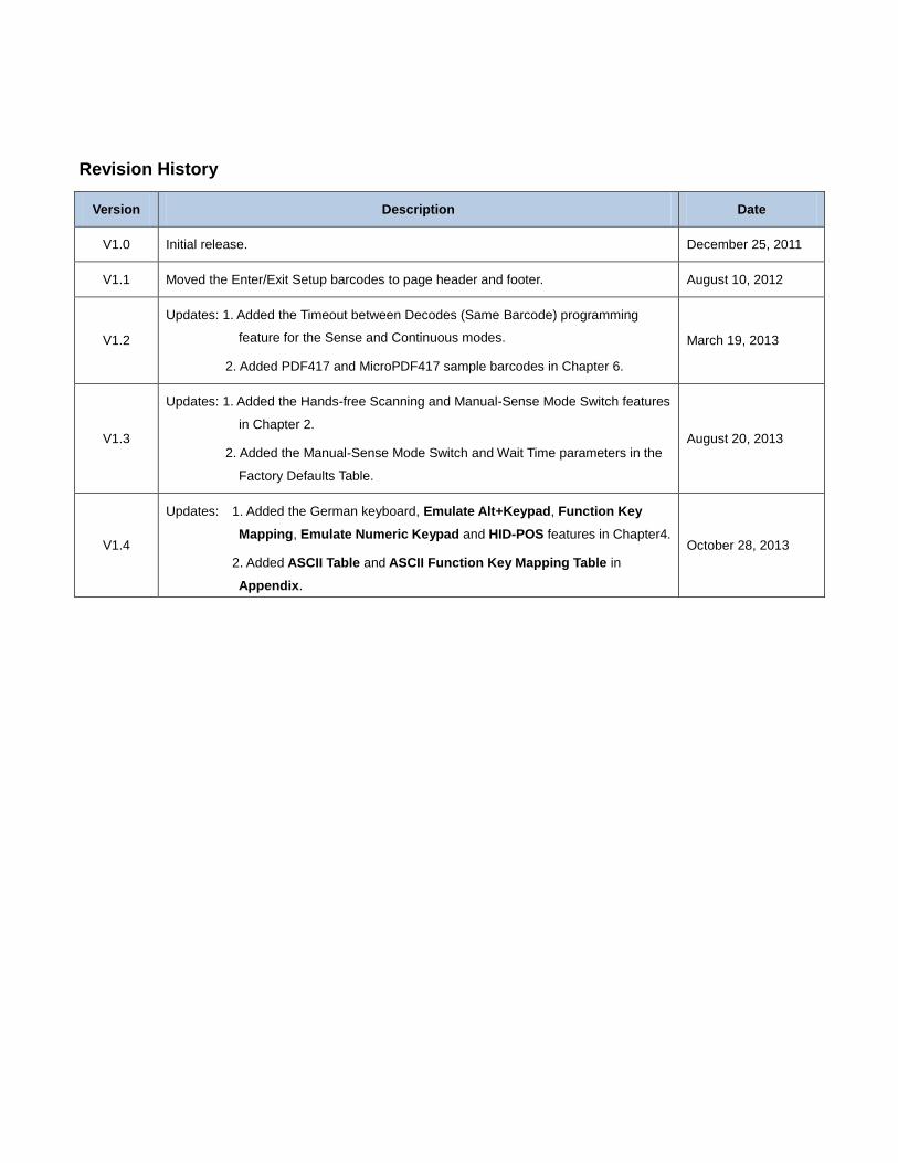
Revision History
Version Description Date
V1.0 Initial release. December 25, 2011
V1.1 Moved the Enter/Exit Setup barcodes to page header and footer. August 10, 2012
V1.2
Updates: 1. Added the Timeout between Decodes (Same Barcode) programming
feature for the Sense and Continuous modes.
2. Added PDF417 and MicroPDF417 sample barcodes in Chapter 6.
March 19, 2013
V1.3
Updates: 1. Added the Hands-free Scanning and Manual-Sense Mode Switch features
in Chapter 2.
2. Added the Manual-Sense Mode Switch and Wait Time parameters in the
Factory Defaults Table.
August 20, 2013
V1.4
Updates: 1. Added the German keyboard, Emulate Alt+Keypad, Function Key
Mapping, Emulate Numeric Keypad and HID-POS features in Chapter4.
2. Added ASCII Table and ASCII Function Key Mapping Table in
Appendix.
October 28, 2013
Table of Contents
Revision History .................................................................................................................................................................... - 3 -
Preface ........................................................................................................................................................................................ 1
Introduction ........................................................................................................................................................................... 1
Chapter Description .............................................................................................................................................................. 1
Document Set ....................................................................................................................................................................... 2
Chapter 1 Getting Started .......................................................................................................................................................... 3
Introduction ........................................................................................................................................................................... 3
Unpacking ............................................................................................................................................................................. 3
Scanner ................................................................................................................................................................................. 3
Data Port ............................................................................................................................................................................... 4
Connect HR15 to a Host ....................................................................................................................................................... 6
Use USB Cable .............................................................................................................................................................. 7
Use RS-232 Cable ......................................................................................................................................................... 7
Use PS/2 Cable ............................................................................................................................................................. 8
Remove Communication Cable ............................................................................................................................................. 9
Power on, Power off, Sleep, Reboot ..................................................................................................................................... 9
Maintenance ........................................................................................................................................................................ 10
Depth of Field ...................................................................................................................................................................... 11
Specifications ...................................................................................................................................................................... 12
Dimensions ......................................................................................................................................................................... 13
Side View ..................................................................................................................................................................... 13
Front View .................................................................................................................................................................... 13
Top View ...................................................................................................................................................................... 14
Scanning Instructions .......................................................................................................................................................... 14
Chapter 2 General Settings ..................................................................................................................................................... 16
Introduction ......................................................................................................................................................................... 16
Barcode Programming ................................................................................................................................................. 16
Command Programming .............................................................................................................................................. 16
Programming Barcode/ Programming Command/Function ................................................................................................. 17
Use of Programming Barcodes ........................................................................................................................................... 17
Use of Command ................................................................................................................................................................ 18
Programming Mode ..................................................................................................................................................... 18
Command Format ........................................................................................................................................................ 18
Configuration Process Flow ......................................................................................................................................... 20
Default Settings ................................................................................................................................................................... 21
Restore Factory Default Settings ................................................................................................................................. 21
Operating Mode Options ..................................................................................................................................................... 22
Scan Mode .......................................................................................................................................................................... 23
Manual Mode ............................................................................................................................................................... 23
Auto Mode .................................................................................................................................................................... 24
Blink Mode ................................................................................................................................................................... 26
Sense Mode ................................................................................................................................................................. 27
Continuous Mode ......................................................................................................................................................... 30
Delayed Sense Mode ................................................................................................................................................... 32
Command Trigger Mode .............................................................................................................................................. 33
Hands-free Scanning (Hardware Version: V1.3 or higher) ........................................................................................... 34
Manual-Sense Mode Switch (Hardware Version: V1.3 or higher) ................................................................................ 34
Security Setup ..................................................................................................................................................................... 35
Good Read Beep ................................................................................................................................................................ 36
Decode Area and Output Interval ........................................................................................................................................ 38
Other Settings ..................................................................................................................................................................... 39
Temporary Mute ........................................................................................................................................................... 39
Chapter 3 Inquiry Command ................................................................................................................................................... 40
Introduction ......................................................................................................................................................................... 40
Chapter 4 Communication Settings ........................................................................................................................................ 41
RS-232 Interface ................................................................................................................................................................. 41
Baud Rate .................................................................................................................................................................... 41
Parity Check ................................................................................................................................................................. 43
Stop Bit ........................................................................................................................................................................ 43
Flow Control ................................................................................................................................................................. 44
Data Bit ........................................................................................................................................................................ 45
USB Interface ...................................................................................................................................................................... 46
USB HID-KBW ............................................................................................................................................................. 46
Keyboard Layout ................................................................................................................................................... 47
Inter-Character Delay ............................................................................................................................................ 48
Convert Case ........................................................................................................................................................ 48
Emulate ALT+Keypad ........................................................................................................................................... 49
Function Key Mapping .......................................................................................................................................... 50
Emulate Numeric Keypad ..................................................................................................................................... 51
USB COM Port Emulation ............................................................................................................................................ 52
HID-POS ...................................................................................................................................................................... 53
Introduction ........................................................................................................................................................... 53
Acquire Scanned Data .......................................................................................................................................... 53
VID/PID ........................................................................................................................................................................ 54
Chapter 5 Data Formatting ...................................................................................................................................................... 55
Introduction ......................................................................................................................................................................... 55
Prefix Sequence .................................................................................................................................................................. 55
Custom Prefix ...................................................................................................................................................................... 56
Enable/Disable Custom Prefix ..................................................................................................................................... 56
Set Custom Prefix ........................................................................................................................................................ 56
AIM ID Prefix ....................................................................................................................................................................... 57
Code ID Prefix ..................................................................................................................................................................... 57
Custom Suffix ...................................................................................................................................................................... 58
Enable/Disable Custom Suffix ...................................................................................................................................... 58
Set Custom Suffix ........................................................................................................................................................ 58
Terminating Character Suffix ............................................................................................................................................... 59
Enable/Disable Terminating Character Suffix ............................................................................................................... 59
Set Terminating Character Suffix .................................................................................................................................. 60
Chapter 6 Symbologies ........................................................................................................................................................... 61
Introduction ......................................................................................................................................................................... 61
Code 128............................................................................................................................................................................. 62
Restore Default Settings .............................................................................................................................................. 62
Enable/Disable Code 128 ............................................................................................................................................ 62
Set Code ID ................................................................................................................................................................. 63
Set Length Range for Code 128 .................................................................................................................................. 64
UCC/EAN-128 ..................................................................................................................................................................... 65
Restore Default Settings .............................................................................................................................................. 65
Enable/Disable UCC/EAN-128 ..................................................................................................................................... 65
Set Code ID ................................................................................................................................................................. 66
Set Length Range for UCC/EAN-128 ........................................................................................................................... 67
AIM 128 ............................................................................................................................................................................... 68
Restore Default Settings .............................................................................................................................................. 68
Enable/Disable AIM 128 ............................................................................................................................................... 68
Set Code ID ................................................................................................................................................................. 69
Set Length Range for AIM 128 ..................................................................................................................................... 70
EAN-8 ................................................................................................................................................................................. 71
Restore Default Settings .............................................................................................................................................. 71
Enable/Disable EAN-8 ................................................................................................................................................. 71
Set Code ID ................................................................................................................................................................. 72
2-Digit Add-On Code .................................................................................................................................................... 73
5-Digit Add-On Code .................................................................................................................................................... 74
EAN-8 Extension .......................................................................................................................................................... 75
Transmit Check Digit .................................................................................................................................................... 75
EAN-13 ............................................................................................................................................................................... 76
Restore Default Settings .............................................................................................................................................. 76
Enable/Disable EAN-13 ............................................................................................................................................... 76
Transmit Check Digit .................................................................................................................................................... 77
Set Code ID ................................................................................................................................................................. 77
2-Digit Add-On Code .................................................................................................................................................... 78
5-Digit Add-On Code .................................................................................................................................................... 79
ISSN .................................................................................................................................................................................... 80
Restore Default Settings .............................................................................................................................................. 80
Enable/Disable ISSN.................................................................................................................................................... 80
Set Code ID ................................................................................................................................................................. 81
ISBN .................................................................................................................................................................................... 82
Restore Default Settings .............................................................................................................................................. 82
Enable/Disable ISBN.................................................................................................................................................... 82
Set ISBN Format .......................................................................................................................................................... 83
Set Code ID ................................................................................................................................................................. 83
UPC-E ................................................................................................................................................................................. 84
Restore Default Settings .............................................................................................................................................. 84
Enable/Disable UPC-E ................................................................................................................................................. 84
Transmit Check Digit .................................................................................................................................................... 85
Set Code ID ................................................................................................................................................................. 85
2-Digit Add-On Code .................................................................................................................................................... 86
5-Digit Add-On Code .................................................................................................................................................... 87
Transmit System Character “0” .................................................................................................................................... 88
UPC-E Extension ......................................................................................................................................................... 88
UPC-A ................................................................................................................................................................................. 89
Restore Default Settings .............................................................................................................................................. 89
Enable/Disable UPC-A ................................................................................................................................................. 89
Set Code ID ................................................................................................................................................................. 90
Transmit Check Digit .................................................................................................................................................... 91
Transmit Preamble Character “0” ................................................................................................................................. 91
2-Digit Add-On Code .................................................................................................................................................... 92
5-Digit Add-On Code .................................................................................................................................................... 93
Interleaved 2 of 5 ................................................................................................................................................................ 94
Restore Default Settings .............................................................................................................................................. 94
Enable/Disable Interleaved 2 of 5 ................................................................................................................................ 94
Set Code ID ................................................................................................................................................................. 95
Check Digit Verification ................................................................................................................................................ 96
Set Length Range for Interleaved 2 of 5 ...................................................................................................................... 97
ITF-6 ................................................................................................................................................................................... 98
Set Code ID ................................................................................................................................................................. 99
ITF-14 ............................................................................................................................................................................... 100
Set Code ID ............................................................................................................................................................... 101
Deutsche 14 ...................................................................................................................................................................... 102
Restore Default Settings ............................................................................................................................................ 102
Enable/Disable Deutsche14 ....................................................................................................................................... 102
Set Code ID ............................................................................................................................................................... 103
Deutsche 12 ...................................................................................................................................................................... 104
Restore Default Settings ............................................................................................................................................ 104
Enable/Disable Deutsche 12 ...................................................................................................................................... 104
Set Code ID ............................................................................................................................................................... 105
COOP 25 (Japanese Matrix 2 of 5) ................................................................................................................................... 106
Restore Default Settings ............................................................................................................................................ 106
Enable/Disable COOP 25 .......................................................................................................................................... 106
Set Code ID ............................................................................................................................................................... 107
Check Digit Verification .............................................................................................................................................. 108
Set Length Range for COOP 25 ................................................................................................................................ 109
Matrix 2 of 5 (European Matrix 2 of 5) ............................................................................................................................... 110
Restore Default Settings ............................................................................................................................................ 110
Enable/Disable Matrix 2 of 5 ...................................................................................................................................... 110
Set Code ID ............................................................................................................................................................... 111
Check Digit Verification .............................................................................................................................................. 112
Set Length Range for Matrix 2 of 5 ............................................................................................................................ 113
Industrial 25....................................................................................................................................................................... 114
Restore Default Settings ............................................................................................................................................ 114
Enable/Disable Industrial 25 ...................................................................................................................................... 114
Set Code ID ............................................................................................................................................................... 115
Check Digit Verification .............................................................................................................................................. 116
Set Length Range for Industrial 25 ............................................................................................................................ 117
Standard 25....................................................................................................................................................................... 118
Restore Default Settings ............................................................................................................................................ 118
Enable/Disable Standard 25 ...................................................................................................................................... 118
Set Code ID ............................................................................................................................................................... 119
Check Digit Verification .............................................................................................................................................. 120
Set Length Range for Standard 25 ............................................................................................................................ 121
Code 39 ............................................................................................................................................................................ 122
Restore Default Settings ............................................................................................................................................ 122
Enable/Disable Code 39 ............................................................................................................................................ 122
Set Code ID ............................................................................................................................................................... 123
Check Digit Verification .............................................................................................................................................. 124
Transmit Start/Stop Character .................................................................................................................................... 125
Enable/Disable Code 39 Full ASCII ........................................................................................................................... 125
Set Length Range for Code 39 .................................................................................................................................. 126
Codabar ............................................................................................................................................................................ 127
Restore Default Settings ............................................................................................................................................ 127
Enable/Disable Codabar ............................................................................................................................................ 127
Set Code ID ............................................................................................................................................................... 128
Check Digit Verification .............................................................................................................................................. 129
Start/Stop Character .................................................................................................................................................. 130
Set Length Range for Codabar .................................................................................................................................. 131
Code 93 ............................................................................................................................................................................ 132
Restore Default Settings ............................................................................................................................................ 132
Enable/Disable Code 93 ............................................................................................................................................ 132
Set Code ID ............................................................................................................................................................... 133
Check Digit Verification .............................................................................................................................................. 134
Set Length Range for Code 93 .................................................................................................................................. 135
Code 11 ............................................................................................................................................................................. 136
Restore Default Settings ............................................................................................................................................ 136
Enable/Disable Code 11 ............................................................................................................................................. 136
Set Code ID ............................................................................................................................................................... 137
Check Digit Verification .............................................................................................................................................. 138
Set Length Range for Code 11 ................................................................................................................................... 139
Plessey ............................................................................................................................................................................. 140
Restore Default Settings ............................................................................................................................................ 140
Enable/Disable Plessey ............................................................................................................................................. 140
Set Code ID ............................................................................................................................................................... 141
Check Digit Verification .............................................................................................................................................. 142
Set Length Range for Plessey ................................................................................................................................... 143
MSI-Plessey ...................................................................................................................................................................... 144
Restore Default Settings ............................................................................................................................................ 144
Enable/Disable MSI-Plessey ...................................................................................................................................... 144
Set Code ID ............................................................................................................................................................... 145
Check Digit Verification .............................................................................................................................................. 146
Set Length Range for MSI-Plessey ............................................................................................................................ 147
GS1 Databar ..................................................................................................................................................................... 148
Restore Default Settings ............................................................................................................................................ 148
Enable/Disable GS1 Databar ..................................................................................................................................... 148
Set Code ID ............................................................................................................................................................... 149
PDF417 ............................................................................................................................................................................. 150
Restore Default Settings ............................................................................................................................................ 150
Enable/Disable PDF417 ............................................................................................................................................. 150
Set Code ID ............................................................................................................................................................... 151
Set Length Range for PDF417 ................................................................................................................................... 152
Sample Barcodes ....................................................................................................................................................... 153
MicroPDF417 .................................................................................................................................................................... 154
Restore Default Settings ............................................................................................................................................ 154
Enable/Disable MicroPDF417 .................................................................................................................................... 154
Set Code ID ............................................................................................................................................................... 155
Set Length Range for MicroPDF417 .......................................................................................................................... 156
Sample Barcodes ....................................................................................................................................................... 157
Chapter 7 Appendix................................................................................................................................................................ 159
Factory Defaults Table....................................................................................................................................................... 159
AIM ID Table ...................................................................................................................................................................... 167
Code ID Table ................................................................................................................................................................... 168
ASCII Table ....................................................................................................................................................................... 169
ASCII Function Key Mapping Table ................................................................................................................................... 173
Digit Barcodes ................................................................................................................................................................... 175
Save/Cancel Barcodes ...................................................................................................................................................... 177
1
Preface
Introduction
This manual provides detailed instructions for setting up and using the NLS-HR1550-30 hand-held barcode scanner
(hereinafter referred to as “HR15 corded scanner” or “the scanner”).
Chapter Description
Chapter 1,Getting Started : This chapter gives a general description of HR15 corded scanner
including its technical parameters.
Chapter 2, General Settings : This chapter introduces two methods to configure the HR15 corded
scanner: barcode programming and command programming.
Chapter 3, Inquiry Command : This chapter describes how to obtain the information of HR15 corded
scanner by scanning programming barcodes.
Chapter 4, Communication Settings : This chapter describes how to configure serial port parameters and USB
function.
Chapter 5, Data Formatting : This chapter describes how to use prefix and suffix to customize scanned
data.
Chapter 6, Symbologies : This chapter lists all compatible symbologies and describes how to
configure the relevant parameters.
Chapter 7, Appendix : This chapter offers factory defaults table and a bunch of frequently used
programming barcodes.
2
Document Set
The documentation set for the HR15 corded scanner provides information for specific user needs and includes:
NLS-HR1550-30 Quick Start Guide Describes how to get the HR15 corded scanner up and running,
and introduces some basic operations.
NLS-HR1550-30 User Guide Describes how to use and set the HR15 corded scanner.
1D Barcode Scanner Firmware Update Utility
User Guide
Describes how to update the firmware in 1D barcode scanners
with this tool developed by Newland.
EzSet123 Barcode Scanner Setup Tool User
Guide
Describes how to configure scanners with this tool developed by
Newland.
3
Chapter 1 Getting Started
Introduction
HR15 corded scanner is a 1D barcode scanner with excellent performance. Besides all common 1D symbologies, it can
also read 2D stacked symbologies such as PDF417 and MicroPDF417. Based on the technology independently
developed by Newland, HR15 corded scanner is able to deliver rapid image acquisition and accurate decoding; it can
provide customers with best services. HR15 corded scanner boasts the ergonomical design that ensures easy and
comfortable operation.
An illustrated introduction to the HR15 corded scanner is included in this chapter. If you have an HR15 device at hand,
make good use of it to develop a better understanding of this manual. This chapter is written for normal users, maintenance
staff and software developers.
Unpacking
Open the package and take out HR15 corded scanner and its accessories. Check to make sure everything on the packing
list is present and intact. If any contents are damaged or missing, please keep the original package and contact your dealer
immediately for after-sale service.
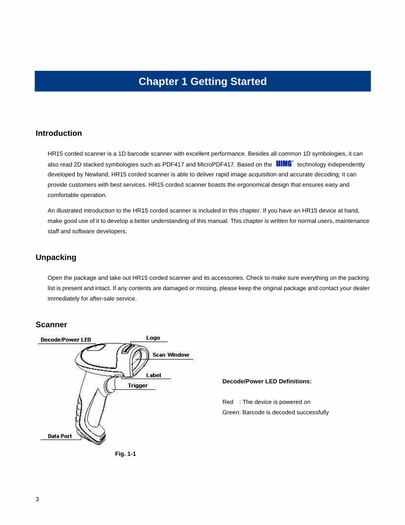
Scanner
Fig. 1-1
Decode/Power LED Definitions:
Red : The device is powered on
Green: Barcode is decoded successfully
4
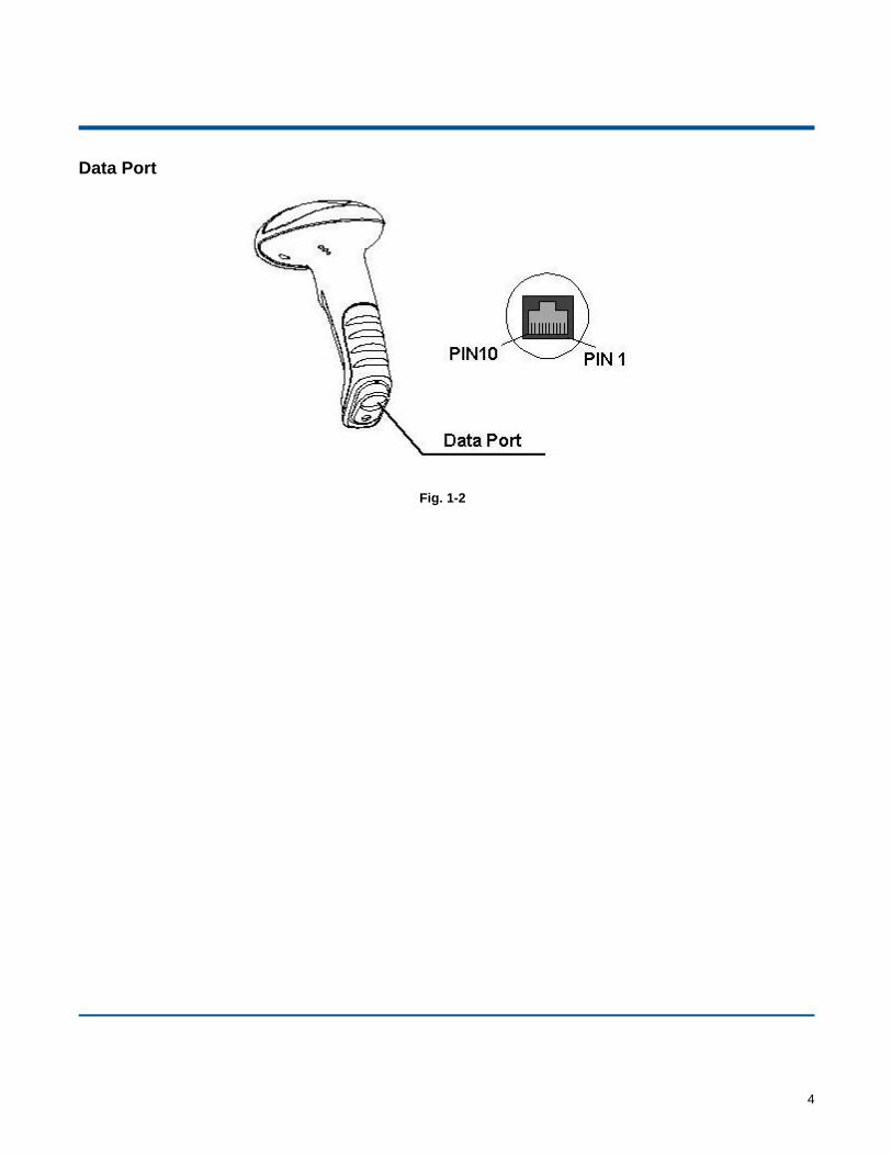
Data Port
Fig. 1-2
5
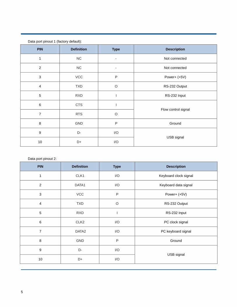
Data port pinout 1 (factory default):
PIN Definition Type Description
1 NC - Not connected
2 NC - Not connected
3 VCC P Power+ (+5V)
4 TXD O RS-232 Output
5 RXD I RS-232 Input
6 CTS I
Flow control signal
7 RTS O
8 GND P Ground
9 D- I/O
USB signal
10 D+ I/O
Data port pinout 2:
PIN Definition Type Description
1 CLK1 I/O Keyboard clock signal
2 DATA1 I/O Keyboard data signal
3 VCC P Power+ (+5V)
4 TXD O RS-232 Output
5 RXD I RS-232 Input
6 CLK2 I/O PC clock signal
7 DATA2 I/O PC keyboard signal
8 GND P Ground
9 D- I/O
USB signal
10 D+ I/O
6
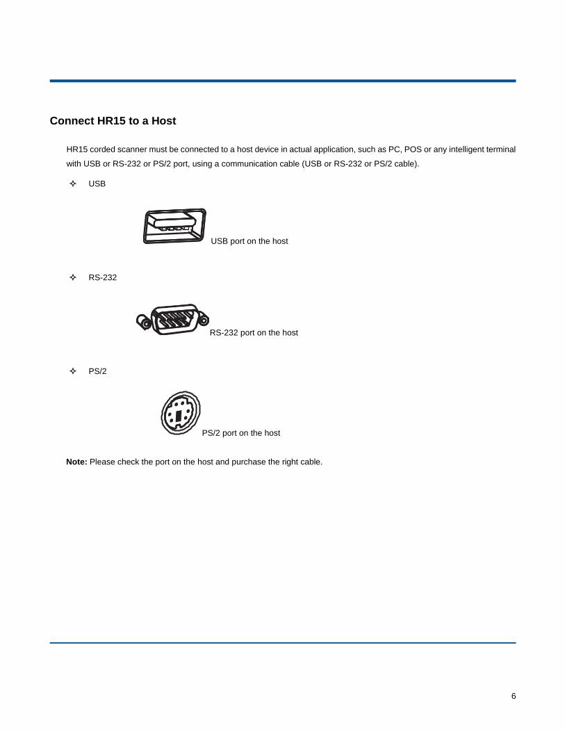
Connect HR15 to a Host
HR15 corded scanner must be connected to a host device in actual application, such as PC, POS or any intelligent terminal
with USB or RS-232 or PS/2 port, using a communication cable (USB or RS-232 or PS/2 cable).
USB
USB port on the host
RS-232
RS-232 port on the host
PS/2
PS/2 port on the host
Note: Please check the port on the host and purchase the right cable.
7
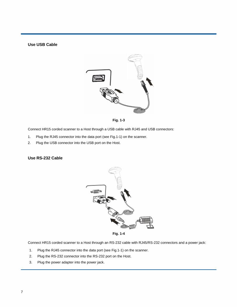
Use USB Cable
Fig. 1-3
Connect HR15 corded scanner to a Host through a USB cable with RJ45 and USB connectors:
1. Plug the RJ45 connector into the data port (see Fig.1-1) on the scanner.
2. Plug the USB connector into the USB port on the Host.
Use RS-232 Cable
Fig. 1-4
Connect HR15 corded scanner to a Host through an RS-232 cable with RJ45/RS-232 connectors and a power jack:
1. Plug the RJ45 connector into the data port (see Fig.1-1) on the scanner.
2. Plug the RS-232 connector into the RS-232 port on the Host.
3. Plug the power adapter into the power jack.
8
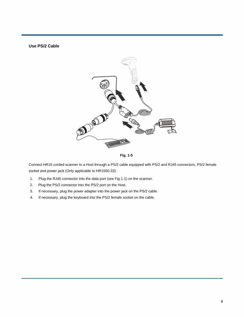
Use PS/2 Cable
Fig. 1-5
Connect HR15 corded scanner to a Host through a PS/2 cable equipped with PS/2 and RJ45 connectors, PS/2 female
socket and power jack (Only applicable to HR1550-33):
1. Plug the RJ45 connector into the data port (see Fig.1-1) on the scanner.
2. Plug the PS/2 connector into the PS/2 port on the Host.
3. If necessary, plug the power adapter into the power jack on the PS/2 cable.
4. If necessary, plug the keyboard into the PS/2 female socket on the cable.
9
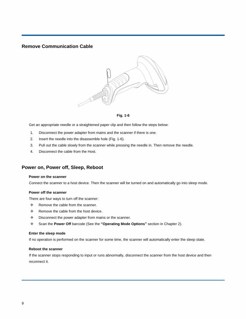
Remove Communication Cable
Fig. 1-6
Get an appropriate needle or a straightened paper clip and then follow the steps below:
1. Disconnect the power adapter from mains and the scanner if there is one.
2. Insert the needle into the disassemble hole (Fig. 1-6).
3. Pull out the cable slowly from the scanner while pressing the needle in. Then remove the needle.
4. Disconnect the cable from the Host.
Power on, Power off, Sleep, Reboot
Power on the scanner
Connect the scanner to a host device. Then the scanner will be turned on and automatically go into sleep mode.
Power off the scanner
There are four ways to turn off the scanner:
Remove the cable from the scanner.
Remove the cable from the host device.
Disconnect the power adapter from mains or the scanner.
Scan the Power Off barcode (See the “Operating Mode Options” section in Chapter 2).
Enter the sleep mode
If no operation is performed on the scanner for some time, the scanner will automatically enter the sleep state.
Reboot the scanner
If the scanner stops responding to input or runs abnormally, disconnect the scanner from the host device and then
reconnect it.
10
Maintenance
The scan window should be kept clean.
Do not scratch the scan window of the device.
Use soft brush to remove the stain from the scan window.
Use the soft cloth to clean the window, such as eyeglass cleaning cloth.
Do not spray any liquid on the scan window.
Clean other parts of the device with water only.
Note: The warranty DOES NOT cover damages caused by inappropriate care and maintenance.
11
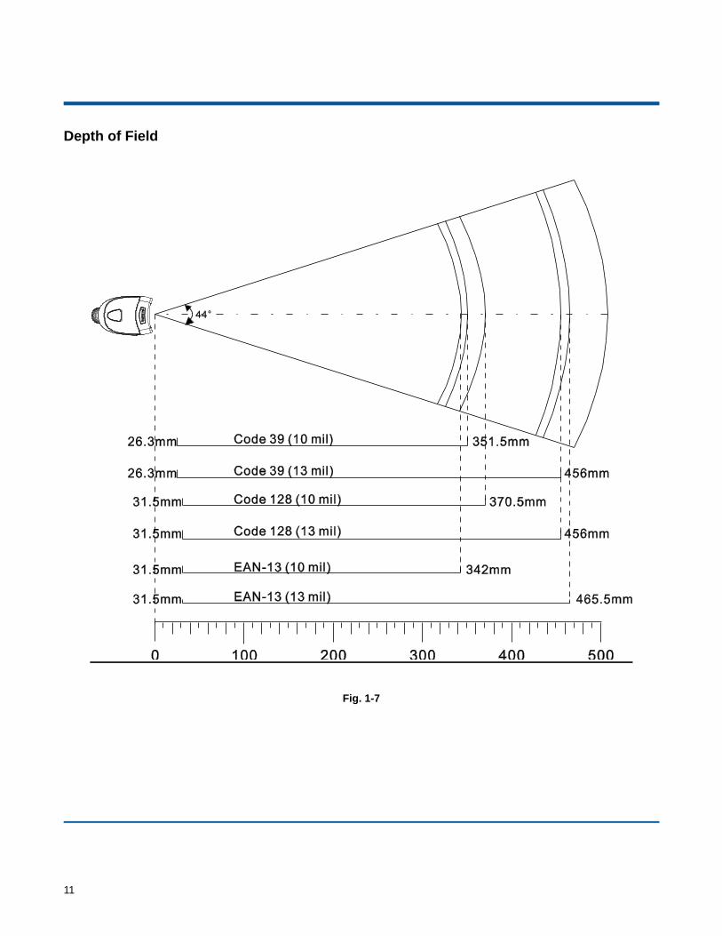
Depth of Field
Fig. 1-7
12
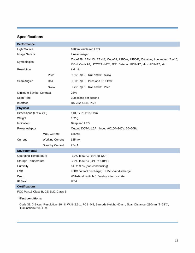
Specifications
Performance
Light Source 620nm visible red LED
Image Sensor Linear imager
Symbologies Code128, EAN-13, EAN-8, Code39, UPC-A, UPC-E, Codabar, Interleaved 2 of 5,
ISBN, Code 93, UCC/EAN-128, GS1 Databar, PDF417, MicroPDF417, etc.
Resolution ≥ 4 mil
Pitch ±55°@ 0°Roll and 0°Skew
Scan Angle* Roll ±30°@ 0°Pitch and 0°Skew
Skew ±75°@ 0°Roll and 0°Pitch
Minimum Symbol Contrast 25%
Scan Rate 300 scans per second
Interface RS-232, USB, PS/2
Physical
Dimensions (L x W x H) 113.5 x 73 x 159 mm
Weight 152 g
Indication Beep and LED
Power Adaptor Output: DC5V, 1.5A Input: AC100~240V, 50~60Hz
Environmental
Operating Temperature -10°C to 50°C (14°F to 122°F)
Storage Temperature -20°C to 60°C (-4°F to 140°F)
Humidity 5% to 95% (non-condensing)
ESD ±8KV contact discharge; ±15KV air discharge
Drop Withstand multiple 1.5m drops to concrete
IP Seal IP54
Certifications
FCC Part15 Class B, CE EMC Class B
*Test conditions:
Code 39, 3 Bytes; Resolution=10mil; W:N=2.5:1; PCS=0.8; Barcode Height=40mm; Scan Distance=210mm, T=23℃,
Illumination= 200 LUX
Current
Max. Current 185mA
Working Current 135mA
Standby Current 75mA
13
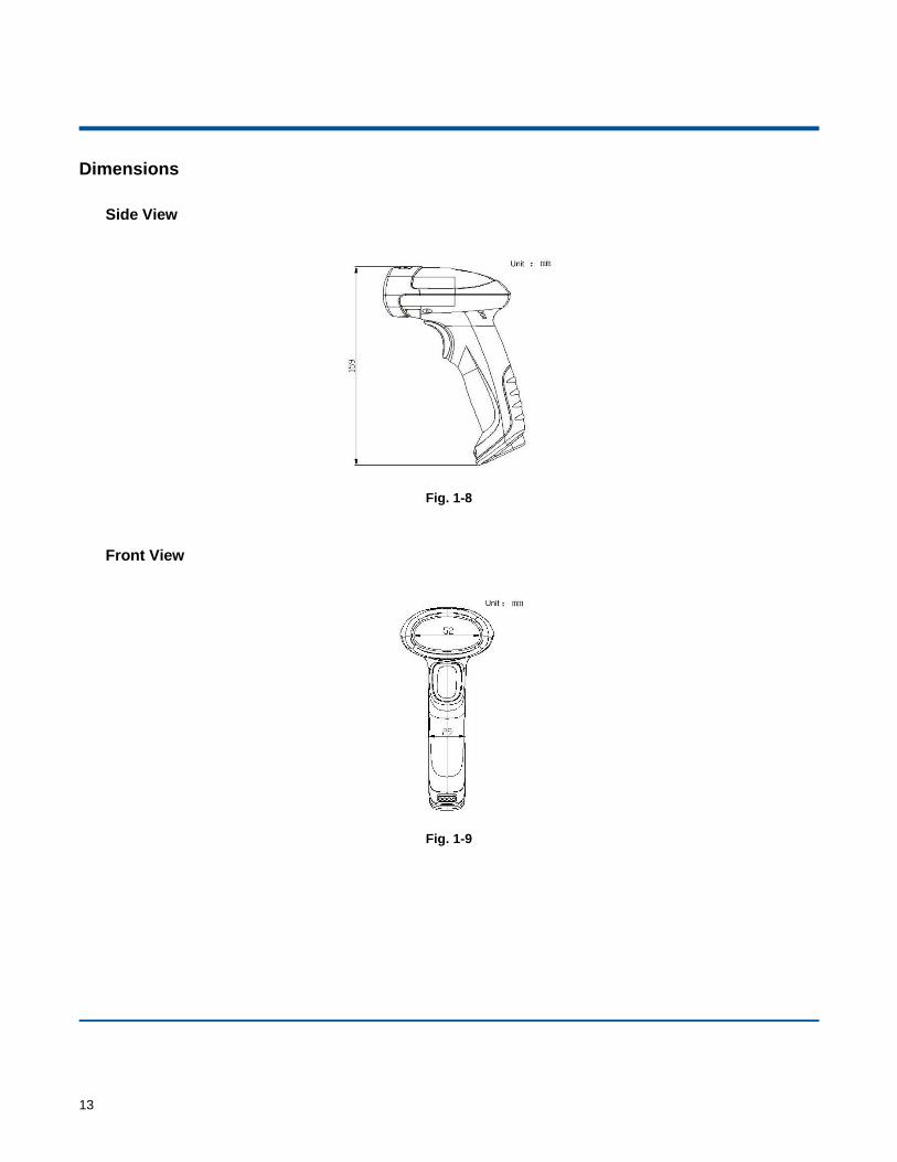
Dimensions
Side View
Fig. 1-8
Front View
Fig. 1-9
14
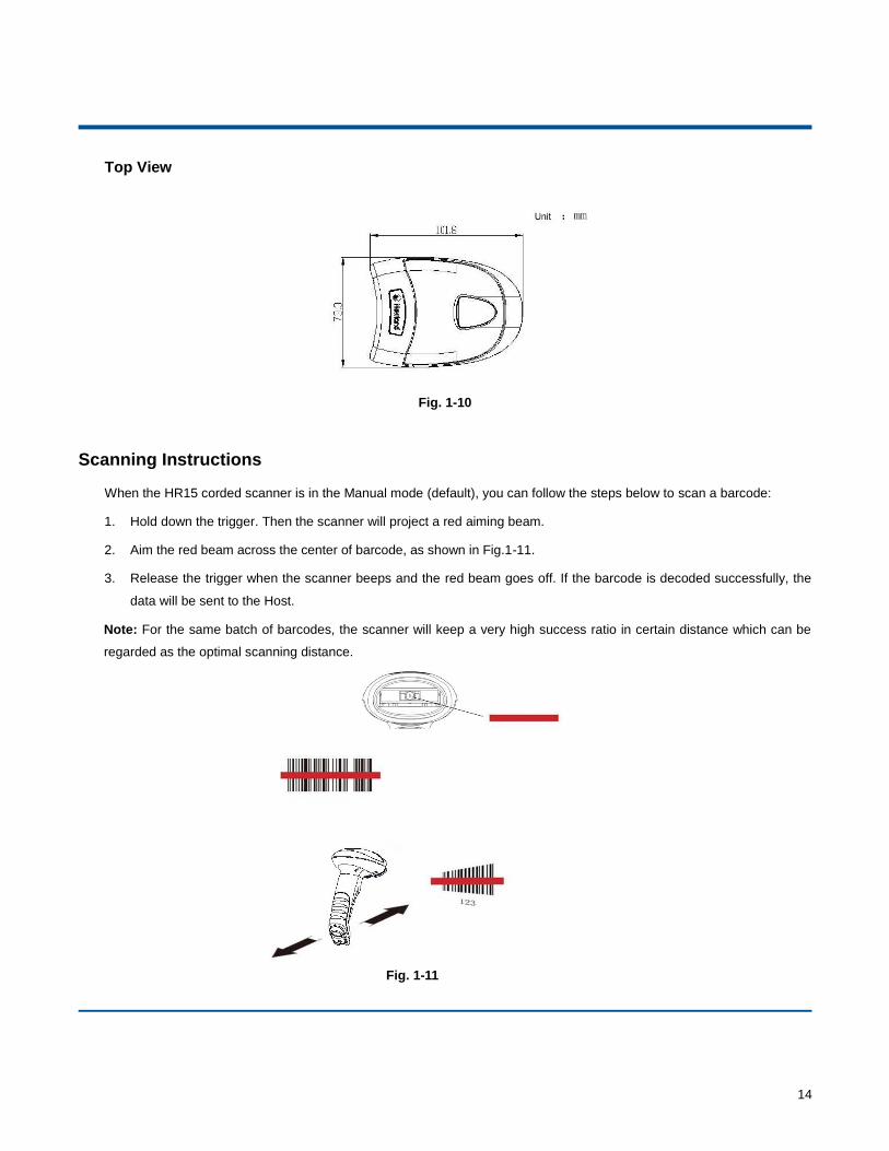
Top View
Fig. 1-10
Scanning Instructions
When the HR15 corded scanner is in the Manual mode (default), you can follow the steps below to scan a barcode:
1. Hold down the trigger. Then the scanner will project a red aiming beam.
2. Aim the red beam across the center of barcode, as shown in Fig.1-11.
3. Release the trigger when the scanner beeps and the red beam goes off. If the barcode is decoded successfully, the
data will be sent to the Host.
Note: For the same batch of barcodes, the scanner will keep a very high success ratio in certain distance which can be
regarded as the optimal scanning distance.
Fig. 1-11
15
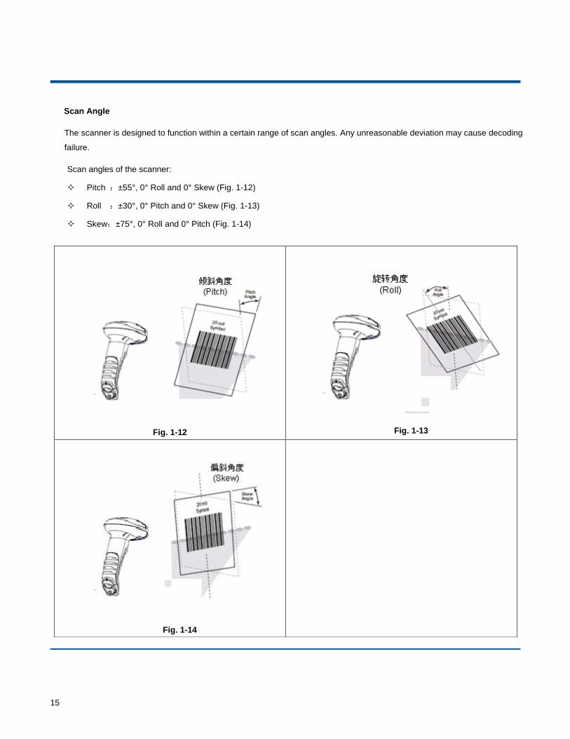
Scan Angle
The scanner is designed to function within a certain range of scan angles. Any unreasonable deviation may cause decoding
failure.
Scan angles of the scanner:
Pitch :±55°, 0° Roll and 0° Skew (Fig. 1-12)
Roll :±30°, 0° Pitch and 0° Skew (Fig. 1-13)
Skew:±75°, 0° Roll and 0° Pitch (Fig. 1-14)
Fig. 1-12
Fig. 1-13
Fig. 1-14
**【Enter Setup】
【Exit Setup】 16
Chapter 2 General Settings
Introduction
There are two ways to configure the HR15 corded scanner: barcode programming and command programming.
Barcode Programming
The HR15 corded scanner scans a series of barcodes to program features. In the following sections, we will explain the
available options and features and provide the barcodes to program them.
This programming method is most straightforward. However, it requires manually scanning barcodes. As a result, errors
are more likely to occur.
Command Programming
You can send the command strings through the Host to your scanner to perform configuration. In the following sections, the
commands will be provided along with programming barcodes.
This configuration can also be performed through our software. For more information, see the “EzSet123 Barcode
Scanner Setup Tool User Guide”.
Note: All settings except temporary ones are stored in non-volatile memory of the scanner and will not be lost by
removing power from the scanner, or turning off/ rebooting the device.
**【Enter Setup】
17 【Exit Setup】
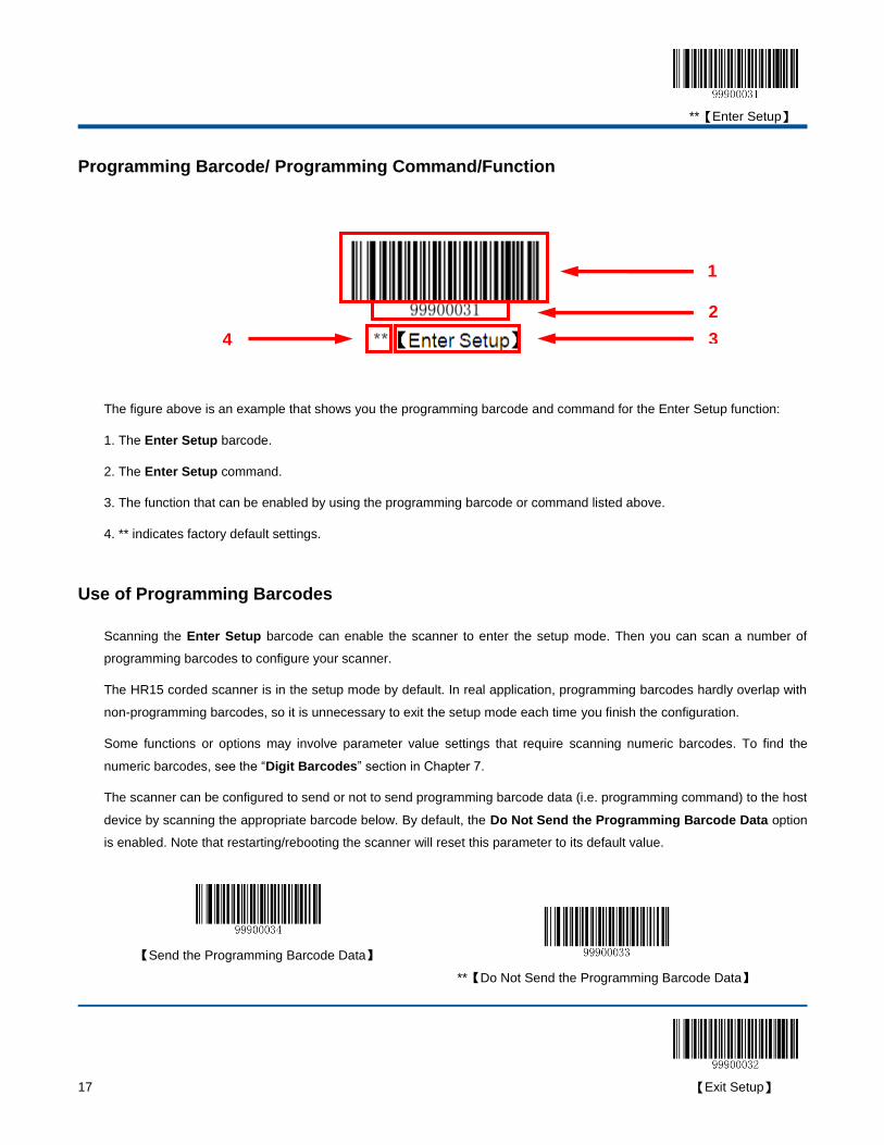
Programming Barcode/ Programming Command/Function
The figure above is an example that shows you the programming barcode and command for the Enter Setup function:
1. The Enter Setup barcode.
2. The Enter Setup command.
3. The function that can be enabled by using the programming barcode or command listed above.
4. ** indicates factory default settings.
Use of Programming Barcodes
Scanning the Enter Setup barcode can enable the scanner to enter the setup mode. Then you can scan a number of
programming barcodes to configure your scanner.
The HR15 corded scanner is in the setup mode by default. In real application, programming barcodes hardly overlap with
non-programming barcodes, so it is unnecessary to exit the setup mode each time you finish the configuration.
Some functions or options may involve parameter value settings that require scanning numeric barcodes. To find the
numeric barcodes, see the “Digit Barcodes” section in Chapter 7.
The scanner can be configured to send or not to send programming barcode data (i.e. programming command) to the host
device by scanning the appropriate barcode below. By default, the Do Not Send the Programming Barcode Data option
is enabled. Note that restarting/rebooting the scanner will reset this parameter to its default value.
【Send the Programming Barcode Data】
**【Do Not Send the Programming Barcode Data】
1
2
3 4
**【Enter Setup】
【Exit Setup】 18
Use of Command
Based on serial port communication, programming commands can be composed of printable ASCII characters, 0x20
(space) through 0x7D (“}”).
Programming Mode
Before configuring the HR15 corded scanner through serial communication, the device must enter the programming mode;
in such mode, the device will only accept and process commands and respond accordingly.
You can enable the device to enter or exit the programming mode by sending the specified commands to it. In the event
that the device receives no data for 5 seconds, it will exit the programming mode automatically.
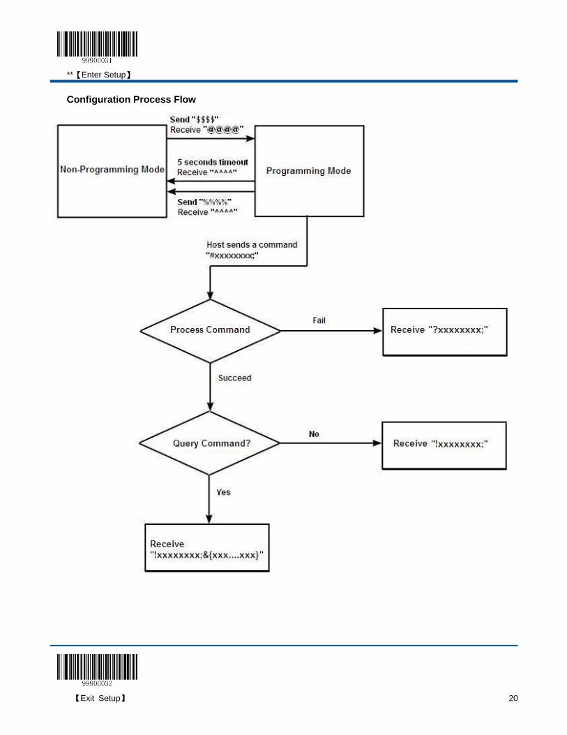
Command Format
1. Enter the programming mode: send “$$$$” from the Host to the scanner, the scanner returns a reply of “@@@@” to
indicate success.
2. Exit the programming mode: send “%%%%” from the Host to the scanner, the scanner returns a reply of “^^^^” to
indicate success.
3. Receiving “^^^^” from the scanner when the Host did not send “%%%%” to it indicates the scanner has
automatically exit the setup mode.
4. A command string consists of “#”, programming command and “;”, such as “#99900030;”.
5. If a command string is properly processed, the scanner will return a reply consisting of “!”, programming command
and “;”, such as “!99900030;”.
6. If the scanner receives an invalid command string or fails to process a command string, it will return a reply consisting
of “?”, programming command and “;”, such as “?99900030;”
7. If a query command is properly processed, the scanner will return a reply containing “!”, programming command and
“;”, as well as "&{", query result and "}". For example:
send a query command of “#99900301;” to get the firmware version information,
the Host will receive a reply of “!99900301;&{Firmware v1.7.5;Decoder v1.00.023.C6;|FD25430B}”.
Description:
In the reply, “Firmware v1.7.5;Decoder v1.00.023.C6” is the query result; “|” is a separator; and “FD25430B” is
the CRC32 checksum value in hexadecimal format.
**【Enter Setup】
19 【Exit Setup】
8. If a command involves parameter(s), they shall be combined as per the rule.
For example: The combined commands for appending terminating character suffix 0x0D (CR),0x0A (LF) to the
scanned data and saving the settings:
“#99904112;#99900000;#99900015;#99900000;#99900012;#99900020;”.
**【Enter Setup】
【Exit Setup】 20
Configuration Process Flow
**【Enter Setup】
21 【Exit Setup】
Default Settings
Restore Factory Default Settings
Scanning the Reset Scanner barcode can restore the scanner to the factory default settings.
You may need to reset your scanner when:
1. scanner is not properly configured so that it fails to decode barcodes;
2. you forget previous configuration and want to avoid its impact;
3. functions that are rarely used have been enabled for the time being.
【Reset Scanner】
**【Enter Setup】
【Exit Setup】 22
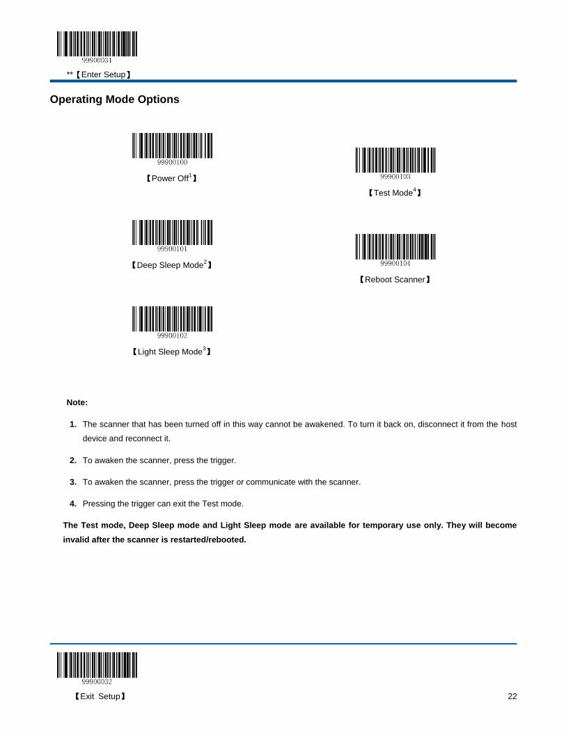
Operating Mode Options
【Power Off1】
【Test Mode4】
【Deep Sleep Mode2】
【Reboot Scanner】
【Light Sleep Mode3】
Note:
1. The scanner that has been turned off in this way cannot be awakened. To turn it back on, disconnect it from the host
device and reconnect it.
2. To awaken the scanner, press the trigger.
3. To awaken the scanner, press the trigger or communicate with the scanner.
4. Pressing the trigger can exit the Test mode.
The Test mode, Deep Sleep mode and Light Sleep mode are available for temporary use only. They will become
invalid after the scanner is restarted/rebooted.
**【Enter Setup】
23 【Exit Setup】
Scan Mode
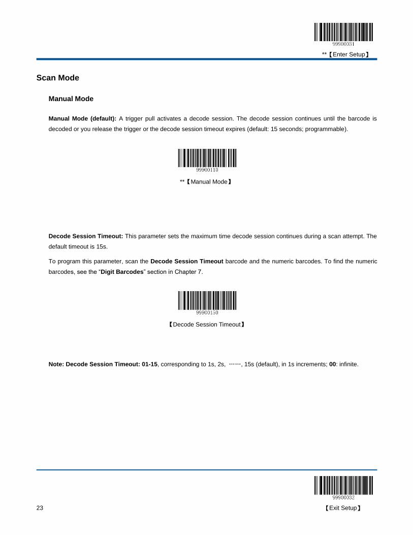
Manual Mode
Manual Mode (default): A trigger pull activates a decode session. The decode session continues until the barcode is
decoded or you release the trigger or the decode session timeout expires (default: 15 seconds; programmable).
**【Manual Mode】
Decode Session Timeout: This parameter sets the maximum time decode session continues during a scan attempt. The
default timeout is 15s.
To program this parameter, scan the Decode Session Timeout barcode and the numeric barcodes. To find the numeric
barcodes, see the “Digit Barcodes” section in Chapter 7.
【Decode Session Timeout】
Note: Decode Session Timeout: 01-15, corresponding to 1s, 2s, ……, 15s (default), in 1s increments; 00: infinite.

**【Enter Setup】
【Exit Setup】 24
Auto Mode
Auto Mode: Pressing the trigger activates a decode session. The decode session continues until the barcode is decoded
or the decode session timeout expires (default: 15 seconds; programmable). The scanner automatically starts one session
after another until you press the trigger a second time.
【Auto Mode】
**【Enter Setup】
25 【Exit Setup】
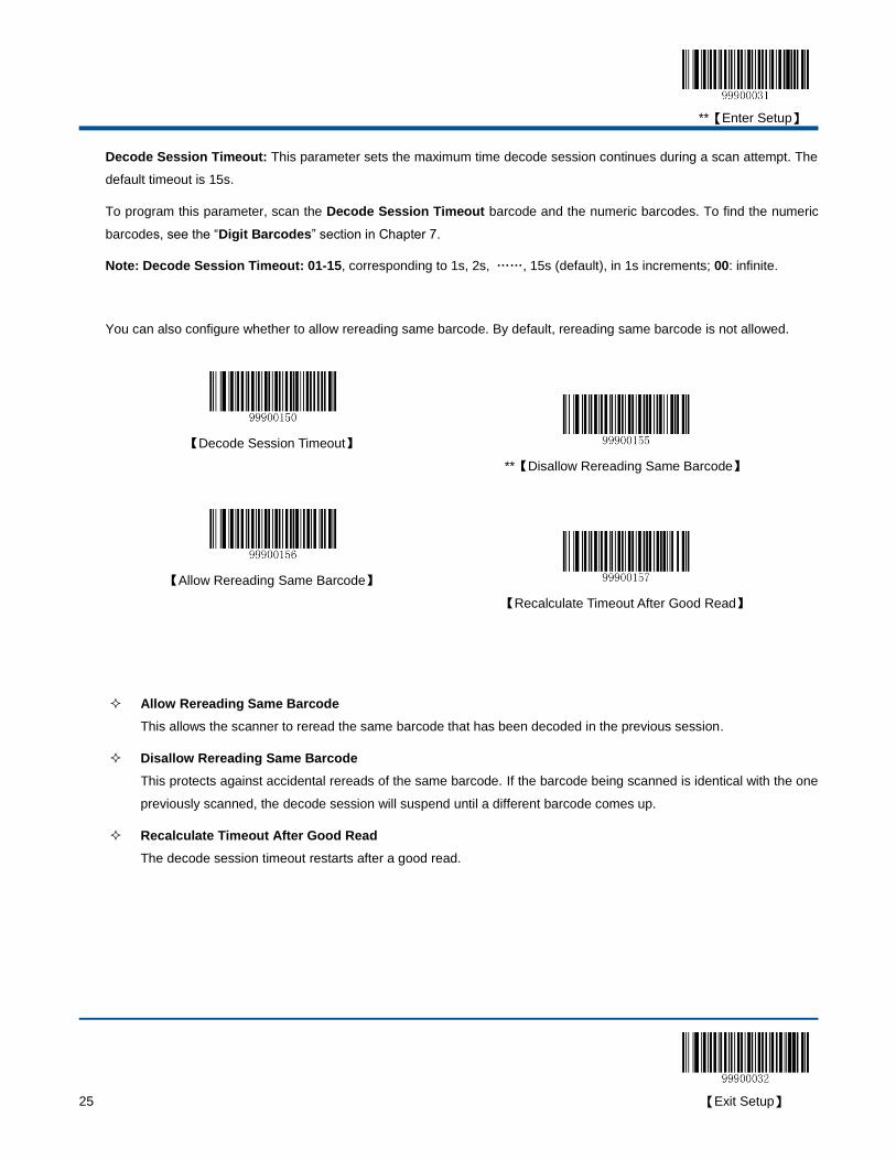
Decode Session Timeout: This parameter sets the maximum time decode session continues during a scan attempt. The
default timeout is 15s.
To program this parameter, scan the Decode Session Timeout barcode and the numeric barcodes. To find the numeric
barcodes, see the “Digit Barcodes” section in Chapter 7.
Note: Decode Session Timeout: 01-15, corresponding to 1s, 2s, ……, 15s (default), in 1s increments; 00: infinite.
You can also configure whether to allow rereading same barcode. By default, rereading same barcode is not allowed.
【Decode Session Timeout】
**【Disallow Rereading Same Barcode】
【Allow Rereading Same Barcode】
【Recalculate Timeout After Good Read】
Allow Rereading Same Barcode
This allows the scanner to reread the same barcode that has been decoded in the previous session.
Disallow Rereading Same Barcode
This protects against accidental rereads of the same barcode. If the barcode being scanned is identical with the one
previously scanned, the decode session will suspend until a different barcode comes up.
Recalculate Timeout After Good Read
The decode session timeout restarts after a good read.
**【Enter Setup】
【Exit Setup】 26
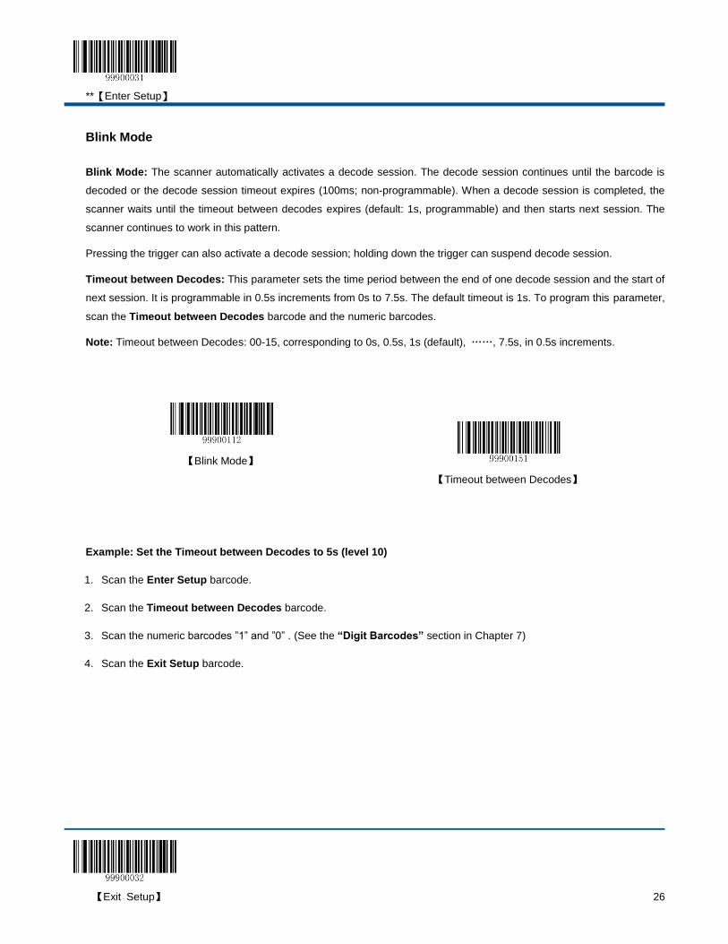
Blink Mode
Blink Mode: The scanner automatically activates a decode session. The decode session continues until the barcode is
decoded or the decode session timeout expires (100ms; non-programmable). When a decode session is completed, the
scanner waits until the timeout between decodes expires (default: 1s, programmable) and then starts next session. The
scanner continues to work in this pattern.
Pressing the trigger can also activate a decode session; holding down the trigger can suspend decode session.
Timeout between Decodes: This parameter sets the time period between the end of one decode session and the start of
next session. It is programmable in 0.5s increments from 0s to 7.5s. The default timeout is 1s. To program this parameter,
scan the Timeout between Decodes barcode and the numeric barcodes.
Note: Timeout between Decodes: 00-15, corresponding to 0s, 0.5s, 1s (default), ……, 7.5s, in 0.5s increments.
【Blink Mode】
【Timeout between Decodes】
Example: Set the Timeout between Decodes to 5s (level 10)
1. Scan the Enter Setup barcode.
2. Scan the Timeout between Decodes barcode.
3. Scan the numeric barcodes ”1” and ”0” . (See the “Digit Barcodes” section in Chapter 7)
4. Scan the Exit Setup barcode.
**【Enter Setup】
27 【Exit Setup】
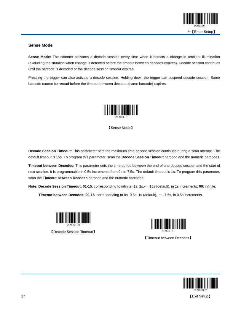
Sense Mode
Sense Mode: The scanner activates a decode session every time when it detects a change in ambient illumination
(excluding the situation when change is detected before the timeout between decodes expires). Decode session continues
until the barcode is decoded or the decode session timeout expires.
Pressing the trigger can also activate a decode session. Holding down the trigger can suspend decode session. Same
barcode cannot be reread before the timeout between decodes (same barcode) expires.
【Sense Mode】
Decode Session Timeout: This parameter sets the maximum time decode session continues during a scan attempt. The
default timeout is 15s. To program this parameter, scan the Decode Session Timeout barcode and the numeric barcodes.
Timeout between Decodes: This parameter sets the time period between the end of one decode session and the start of
next session. It is programmable in 0.5s increments from 0s to 7.5s. The default timeout is 1s. To program this parameter,
scan the Timeout between Decodes barcode and the numeric barcodes.
Note: Decode Session Timeout: 01-15, corresponding to infinite, 1s, 2s,…, 15s (default), in 1s increments; 00: infinite.
Timeout between Decodes: 00-15, corresponding to 0s, 0.5s, 1s (default), …, 7.5s, in 0.5s increments.
【Decode Session Timeout】
【Timeout between Decodes】
**【Enter Setup】
【Exit Setup】 28
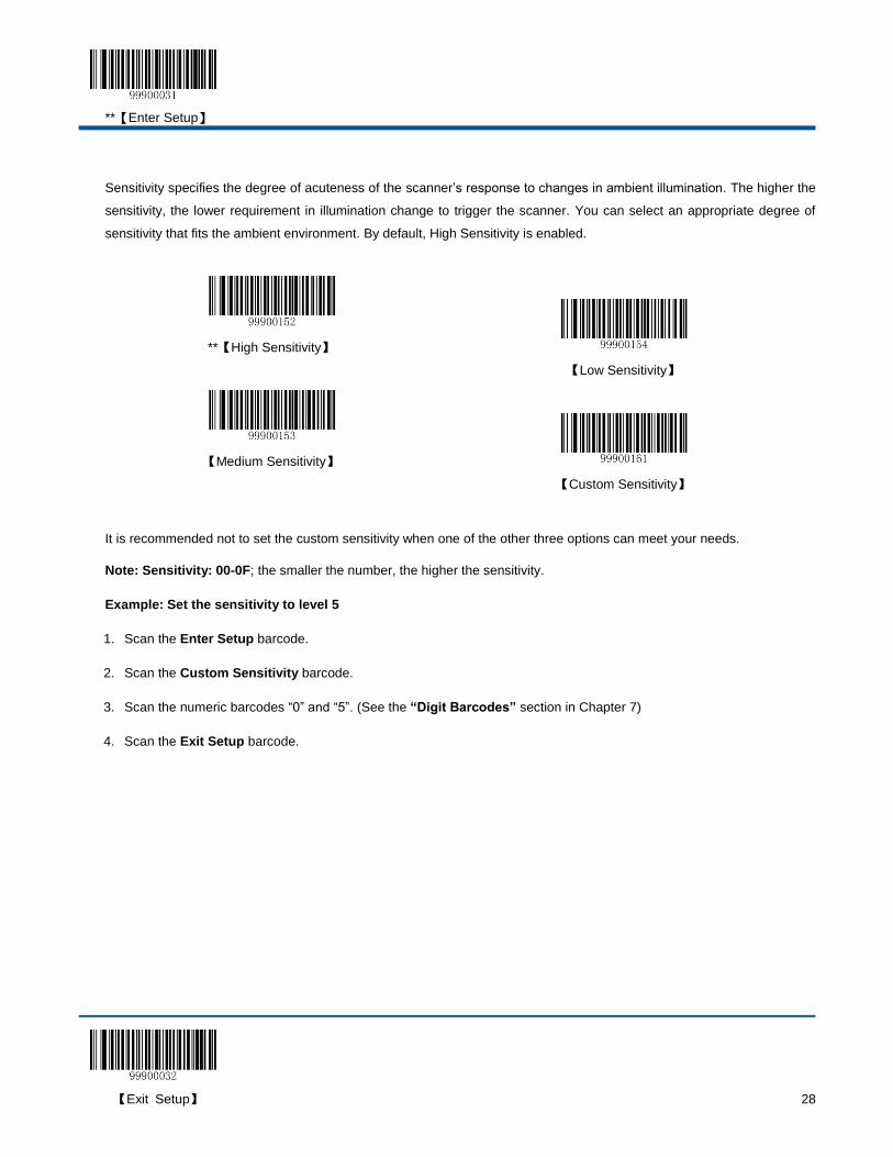
Sensitivity specifies the degree of acuteness of the scanner’s response to changes in ambient illumination. The higher the
sensitivity, the lower requirement in illumination change to trigger the scanner. You can select an appropriate degree of
sensitivity that fits the ambient environment. By default, High Sensitivity is enabled.
**【High Sensitivity】
【Low Sensitivity】
【Medium Sensitivity】
【Custom Sensitivity】
It is recommended not to set the custom sensitivity when one of the other three options can meet your needs.
Note: Sensitivity: 00-0F; the smaller the number, the higher the sensitivity.
Example: Set the sensitivity to level 5
1. Scan the Enter Setup barcode.
2. Scan the Custom Sensitivity barcode.
3. Scan the numeric barcodes “0” and “5”. (See the “Digit Barcodes” section in Chapter 7)
4. Scan the Exit Setup barcode.
**【Enter Setup】
29 【Exit Setup】
Timeout between Decodes (Same Barcode): This parameter sets the minimum time between decodes for the same
barcode. It protects against accidental rereads of the same barcode. It is programmable in 0.1s increments from 0s to 12s.
If you want to stop the scanner from rereading the same barcode, set this parameter to 127. The default timeout is 1.6s. To
program this parameter, scan the Timeout between Decodes (Same Barcode) barcode, the numeric barcode(s) and the
Save barcode.
【Timeout between Decodes (Same Barcode)】
Note: Timeout between Decodes (Same Barcode): 0-120, corresponding to 0s, 0.1s, …, 1.6s (default), …, 12s, in 0.1s
increments; 127: infinite.
Example: Set the timeout between decodes (same barcode) to 5s
1. Scan the Enter Setup barcode.
2. Scan the Timeout between Decodes (Same Barcode) barcode.
3. Scan the numeric barcodes “5” and “0”. (See the “Digit Barcodes” section in Chapter 7)
4. Scan the Save barcode. (See the “Save/Cancel Barcodes” section in Chapter 7)
5. Scan the Exit Setup barcode.
**【Enter Setup】
【Exit Setup】 30
Continuous Mode
Continuous Mode: The scanner automatically activates a decode session. The decode session continues until the
barcode is decoded. When a decode session is completed, the scanner waits until the timeout between decodes expires
and then starts next session. The scanner continues to work in this pattern. Same barcode cannot be reread before the
timeout between decodes (same barcode) expires.
Holding down the trigger can also activate the scanner to decode continuously, but with no intervals (i.e. timeout between
decodes will be ignored).
【Continuous Mode】
**【Enter Setup】
31 【Exit Setup】
Timeout between Decodes: This parameter sets the time period between the end of one decode session and the start of
next session. It is programmable in 0.5s increments from 0s to 7.5s. The default timeout is 1s. To program this parameter,
scan the Timeout between Decodes barcode and the numeric barcodes.
Note: Timeout between Decodes: 00-15, corresponding to 0s, 0.5s, 1s (default), ……, 7.5s, in 0.5s increments.
【Timeout between Decodes】
Timeout between Decodes (Same Barcode): This parameter sets the minimum time between decodes for the same
barcode. It protects against accidental rereads of the same barcode. It is programmable in 0.1s increments from 0s to 12s.
If you want to stop the scanner from rereading the same barcode, set this parameter to 127. The default timeout is 1.6s. To
program this parameter, scan the Timeout between Decodes (Same Barcode) barcode, the numeric barcodes and the
Save barcode.
Note: Timeout between Decodes (Same Barcode): 0-120, corresponding to 0s, 0.1s, …, 1.6s (default), …, 12s, in 0.1s
increments; 127: infinite.
【Timeout between Decodes (Same Barcode)】
Example: Set the timeout between decodes (same barcode) to 5s:
1. Scan the Enter Setup barcode.
2. Scan the Timeout between Decodes (Same Barcode) barcode.
3. Scan the numeric barcodes “5” and “0”. (See the “Digit Barcodes” section in Chapter 7)
4. Scan the Save barcode. (See the “Save/Cancel Barcodes” section in Chapter 7)
5. Scan the Exit Setup barcode.
**【Enter Setup】
【Exit Setup】 32
Delayed Sense Mode
Delayed Sense Mode: The scanner automatically activates a decode session when it detects a change in ambient
illumination. The decode session continues until the barcode is decoded or the decode session timeout expires. When a
decode session is completed, the scanner waits 200ms and then starts to monitor ambient environment until it detects a
change to trigger next decode session. Same barcode cannot be reread before the timeout between decodes (same
barcode) expires.
【Delayed Sense Mode】
Decode Session Timeout: This parameter sets the maximum time decode session continues during a scan attempt. To
program this parameter, scan the Decode Session Timeout barcode and the numeric barcodes.
Timeout between Decodes (Same Barcode): This parameter sets the minimum time between decodes for the same
barcode. It protects against accidental rereads of the same barcode. It is programmable in 0.2s increments from 0s to 3s.
To program this parameter, scan the Timeout between Decodes (Same Barcode) barcode and the numeric barcodes.
Note: Decode Session Timeout: 01-15, corresponding to 2s, 4s,…, 30s, in 2s increments; 00: infinite.
Timeout between Decodes (Same Barcode): 00-15, corresponding to 0s, 0.2s,…,3s,in 0.2s increments.
【Decode Session Timeout】
【Timeout between Decodes (Same Barcode)】
**【Enter Setup】
33 【Exit Setup】
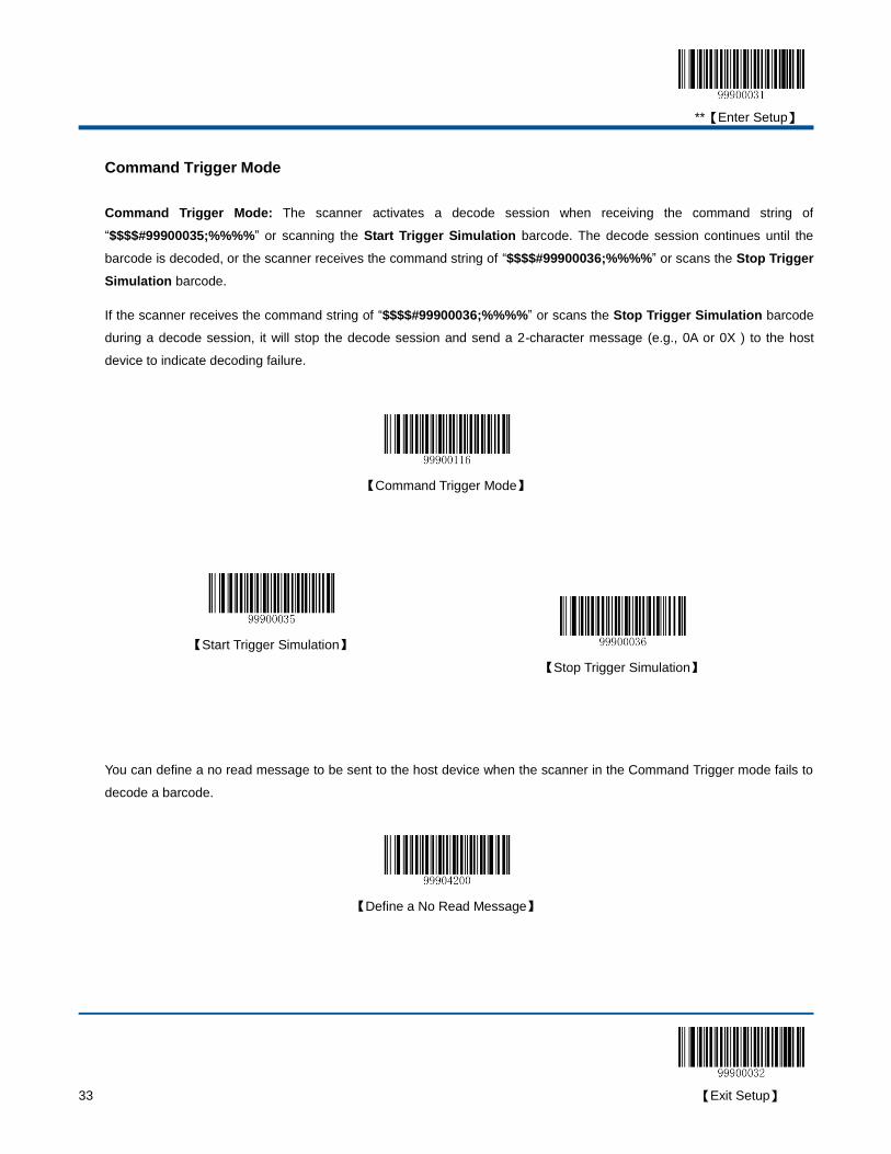
Command Trigger Mode
Command Trigger Mode: The scanner activates a decode session when receiving the command string of
“$$$$#99900035;%%%%” or scanning the Start Trigger Simulation barcode. The decode session continues until the
barcode is decoded, or the scanner receives the command string of “$$$$#99900036;%%%%” or scans the Stop Trigger
Simulation barcode.
If the scanner receives the command string of “$$$$#99900036;%%%%” or scans the Stop Trigger Simulation barcode
during a decode session, it will stop the decode session and send a 2-character message (e.g., 0A or 0X ) to the host
device to indicate decoding failure.
【Command Trigger Mode】
【Start Trigger Simulation】
【Stop Trigger Simulation】
You can define a no read message to be sent to the host device when the scanner in the Command Trigger mode fails to
decode a barcode.
【Define a No Read Message】
**【Enter Setup】
【Exit Setup】 34
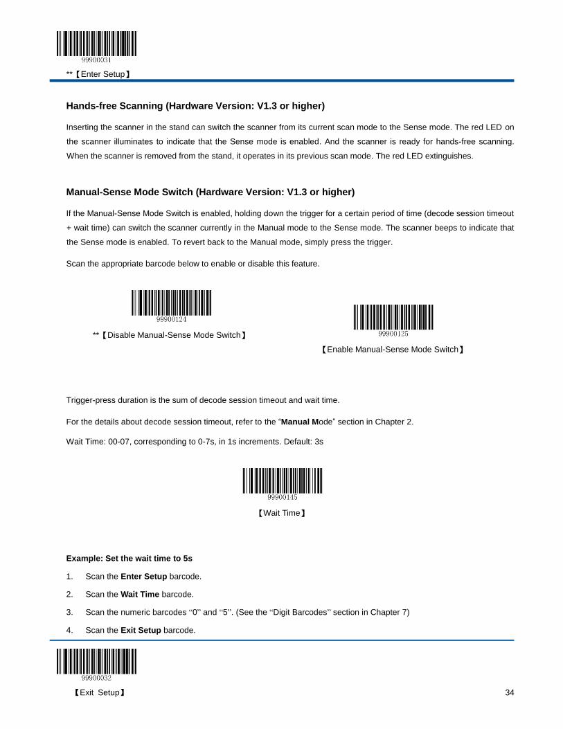
Hands-free Scanning (Hardware Version: V1.3 or higher)
Inserting the scanner in the stand can switch the scanner from its current scan mode to the Sense mode. The red LED on
the scanner illuminates to indicate that the Sense mode is enabled. And the scanner is ready for hands-free scanning.
When the scanner is removed from the stand, it operates in its previous scan mode. The red LED extinguishes.
Manual-Sense Mode Switch (Hardware Version: V1.3 or higher)
If the Manual-Sense Mode Switch is enabled, holding down the trigger for a certain period of time (decode session timeout
+ wait time) can switch the scanner currently in the Manual mode to the Sense mode. The scanner beeps to indicate that
the Sense mode is enabled. To revert back to the Manual mode, simply press the trigger.
Scan the appropriate barcode below to enable or disable this feature.
**【Disable Manual-Sense Mode Switch】
【Enable Manual-Sense Mode Switch】
Trigger-press duration is the sum of decode session timeout and wait time.
For the details about decode session timeout, refer to the “Manual Mode” section in Chapter 2.
Wait Time: 00-07, corresponding to 0-7s, in 1s increments. Default: 3s
【Wait Time】
Example: Set the wait time to 5s
1. Scan the Enter Setup barcode.
2. Scan the Wait Time barcode.
3. Scan the numeric barcodes “0” and “5”. (See the “Digit Barcodes” section in Chapter 7)
4. Scan the Exit Setup barcode.
**【Enter Setup】
35 【Exit Setup】
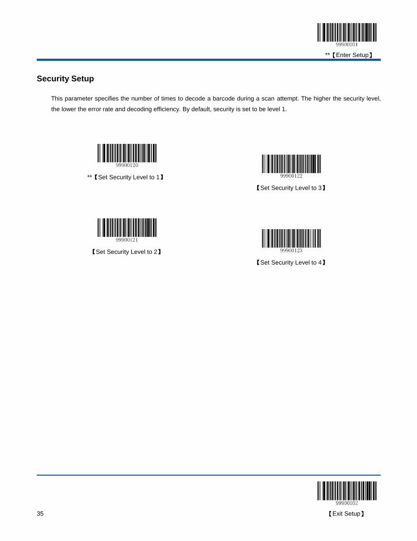
Security Setup
This parameter specifies the number of times to decode a barcode during a scan attempt. The higher the security level,
the lower the error rate and decoding efficiency. By default, security is set to be level 1.
**【Set Security Level to 1】
【Set Security Level to 3】
【Set Security Level to 2】
【Set Security Level to 4】

**【Enter Setup】
【Exit Setup】 36
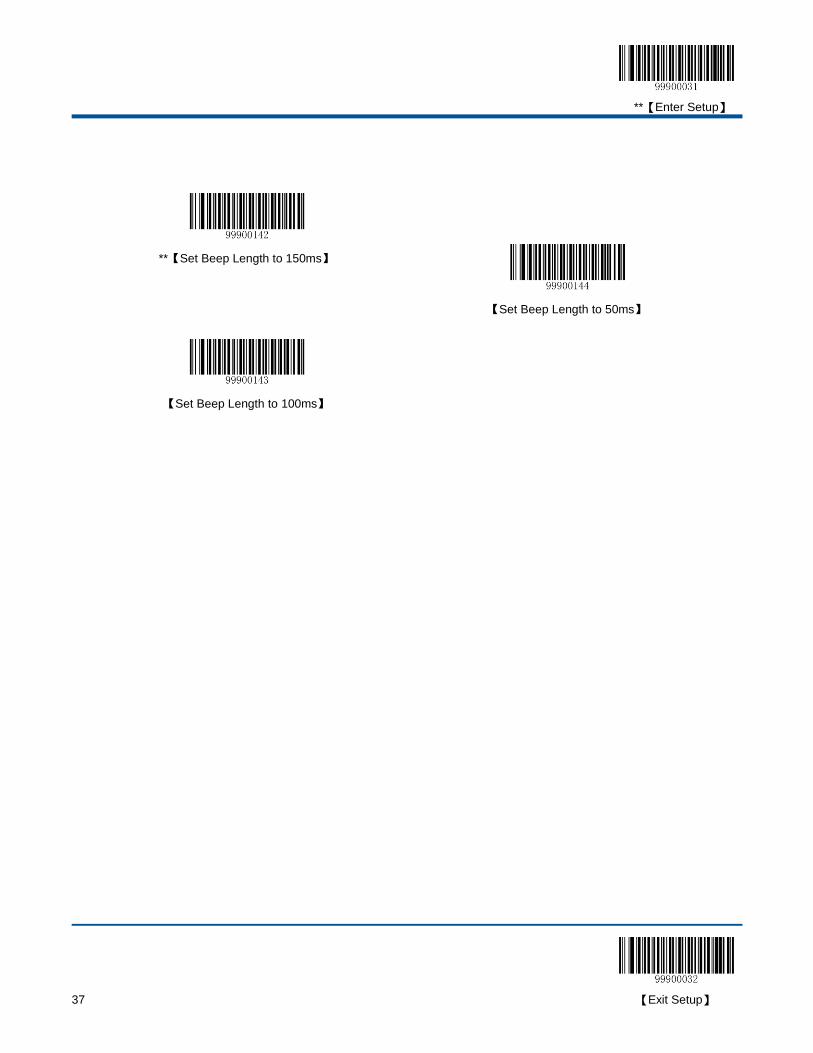
Good Read Beep
By default, the scanner emits a medium-pitched loud beep that lasts 150ms after good read.
【Do Not Beep After Good Read】
【Medium-Pitched Medium-Loud Beep】
【High-Pitched Loud Beep】
【Medium-Pitched Low Beep】
【High-Pitched Medium-Loud Beep】
【Low-Pitched Loud Beep】
【High-Pitched Low Beep】
【Low-Pitched Medium-Loud Beep】
**【Medium-Pitched Loud Beep】
【Low-Pitched Low Beep】
**【Enter Setup】
37 【Exit Setup】
**【Set Beep Length to 150ms】
【Set Beep Length to 50ms】
【Set Beep Length to 100ms】
**【Enter Setup】
【Exit Setup】 38
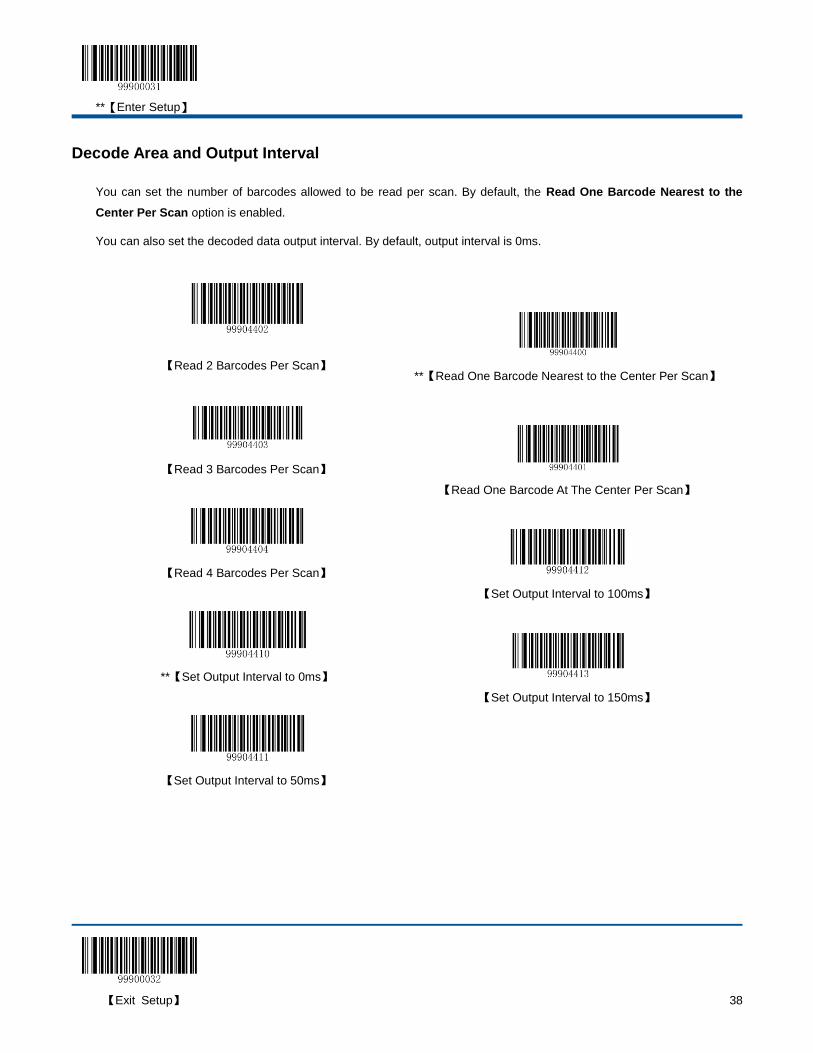
Decode Area and Output Interval
You can set the number of barcodes allowed to be read per scan. By default, the Read One Barcode Nearest to the
Center Per Scan option is enabled.
You can also set the decoded data output interval. By default, output interval is 0ms.
【Read 2 Barcodes Per Scan】
**【Read One Barcode Nearest to the Center Per Scan】
【Read 3 Barcodes Per Scan】
【Read One Barcode At The Center Per Scan】
【Read 4 Barcodes Per Scan】
【Set Output Interval to 100ms】
**【Set Output Interval to 0ms】
【Set Output Interval to 150ms】
【Set Output Interval to 50ms】
**【Enter Setup】
39 【Exit Setup】
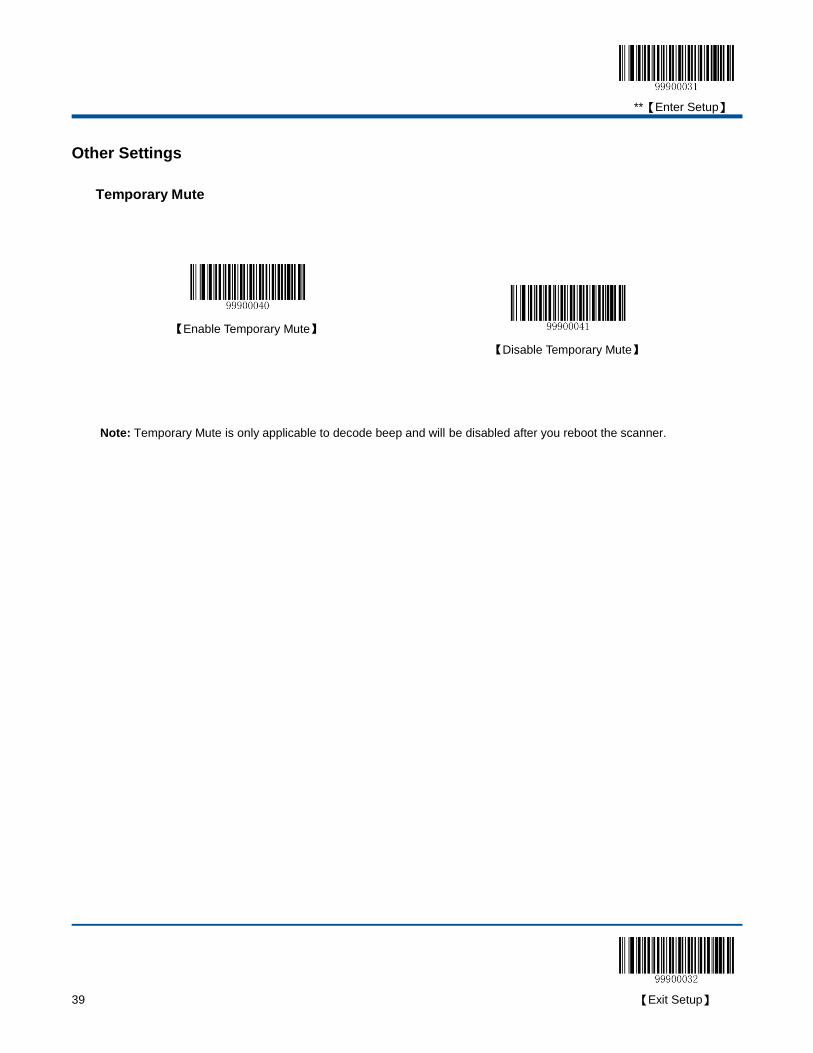
Other Settings
Temporary Mute
【Enable Temporary Mute】
【Disable Temporary Mute】
Note: Temporary Mute is only applicable to decode beep and will be disabled after you reboot the scanner.

**【Enter Setup】
【Exit Setup】 40
Chapter 3 Inquiry Command
Introduction
You can scan one of the barcodes below to inquire the scanner information. The results will be sent to the Host.
【Inquire all Information】
【Inquire the Manufacture Date】
【Inquire the Firmware Version】
【Inquire the Model Number】
【Inquire the Serial Number】
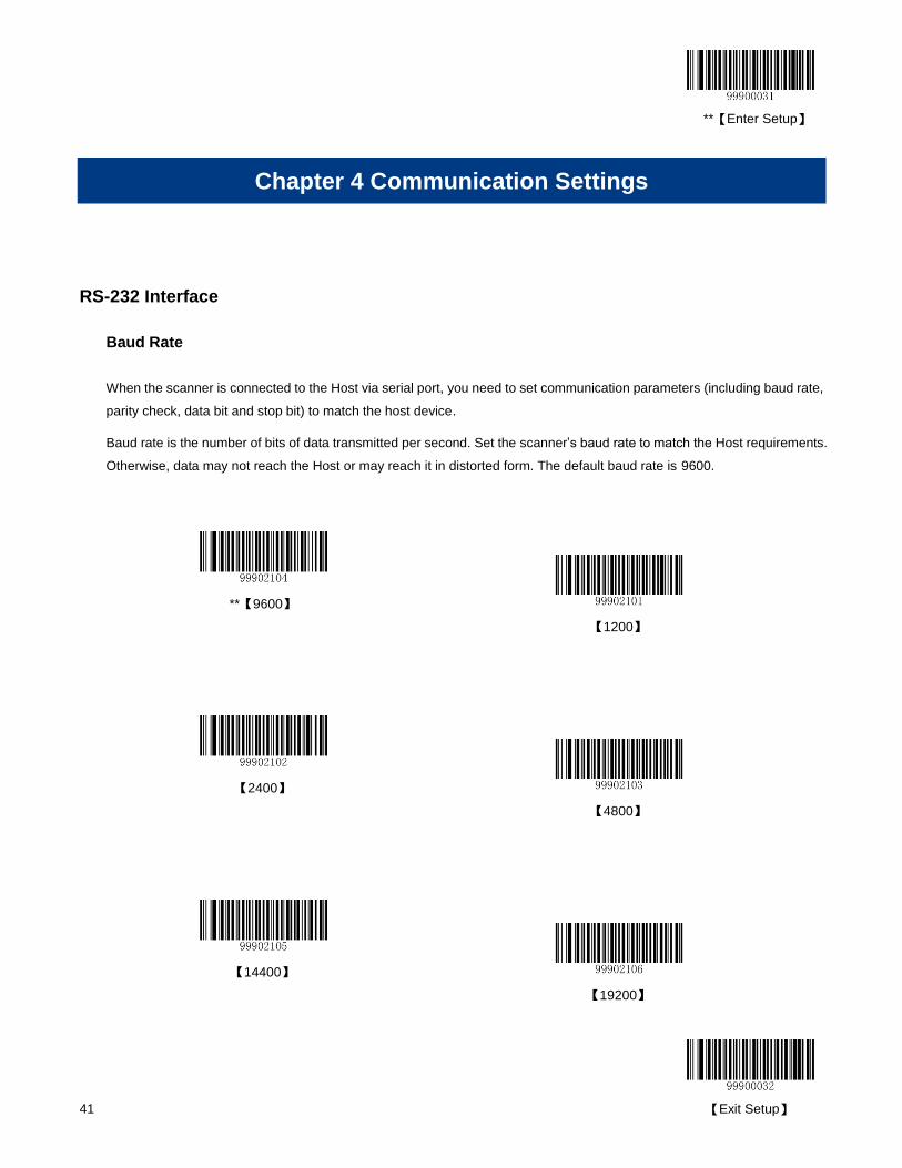
**【Enter Setup】
41 【Exit Setup】
Chapter 4 Communication Settings
RS-232 Interface
Baud Rate
When the scanner is connected to the Host via serial port, you need to set communication parameters (including baud rate,
parity check, data bit and stop bit) to match the host device.
Baud rate is the number of bits of data transmitted per second. Set the scanner’s baud rate to match the Host requirements.
Otherwise, data may not reach the Host or may reach it in distorted form. The default baud rate is 9600.
**【9600】
【1200】
【2400】
【4800】
【14400】
【19200】
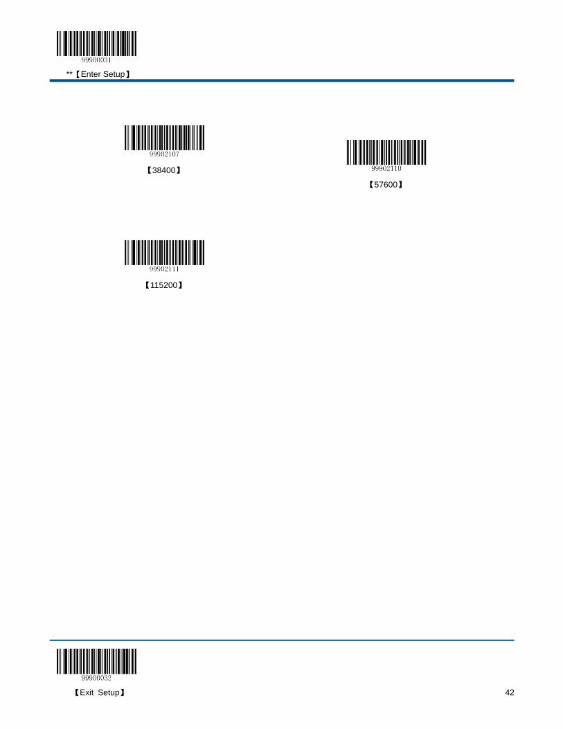
**【Enter Setup】
【Exit Setup】 42
【38400】
【57600】
【115200】
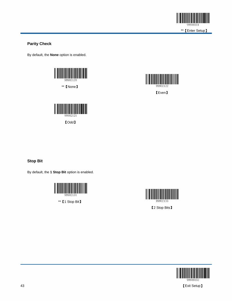
**【Enter Setup】
43 【Exit Setup】
Parity Check
By default, the None option is enabled.
**【None】
【Even】
【Odd】
Stop Bit
By default, the 1 Stop Bit option is enabled.
**【1 Stop Bit】
【2 Stop Bits】
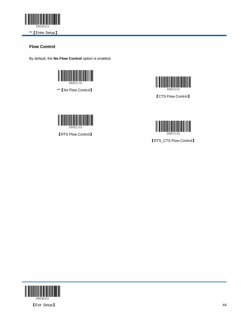
**【Enter Setup】
【Exit Setup】 44
Flow Control
By default, the No Flow Control option is enabled.
**【No Flow Control】
【CTS Flow Control】
【RTS Flow Control】
【RTS_CTS Flow Control】
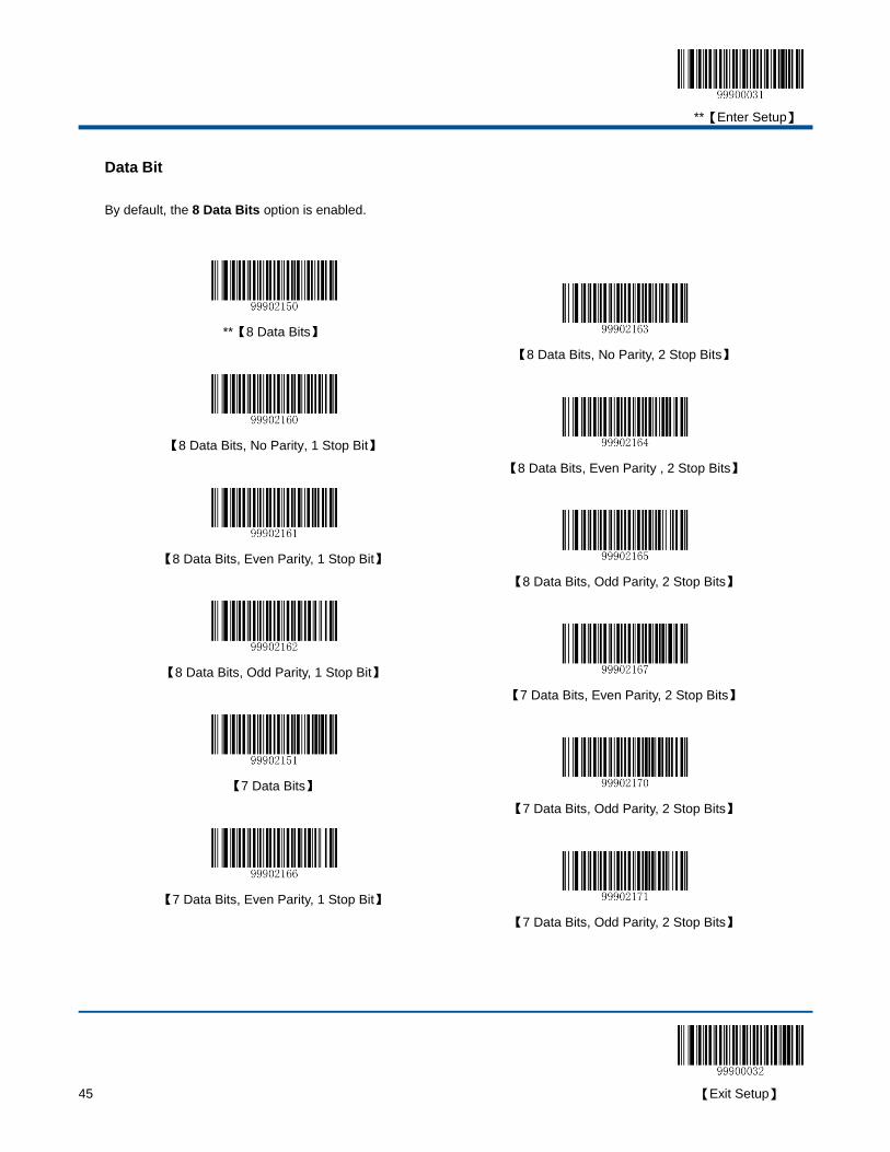
**【Enter Setup】
45 【Exit Setup】
Data Bit
By default, the 8 Data Bits option is enabled.
**【8 Data Bits】
【8 Data Bits, No Parity, 2 Stop Bits】
【8 Data Bits, No Parity, 1 Stop Bit】
【8 Data Bits, Even Parity , 2 Stop Bits】
【8 Data Bits, Even Parity, 1 Stop Bit】
【8 Data Bits, Odd Parity, 2 Stop Bits】
【8 Data Bits, Odd Parity, 1 Stop Bit】
【7 Data Bits, Even Parity, 2 Stop Bits】
【7 Data Bits】
【7 Data Bits, Odd Parity, 2 Stop Bits】
【7 Data Bits, Even Parity, 1 Stop Bit】
【7 Data Bits, Odd Parity, 2 Stop Bits】
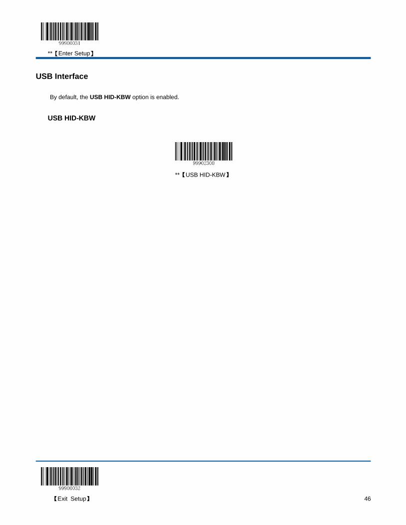
**【Enter Setup】
【Exit Setup】 46
USB Interface
By default, the USB HID-KBW option is enabled.
USB HID-KBW
**【USB HID-KBW】
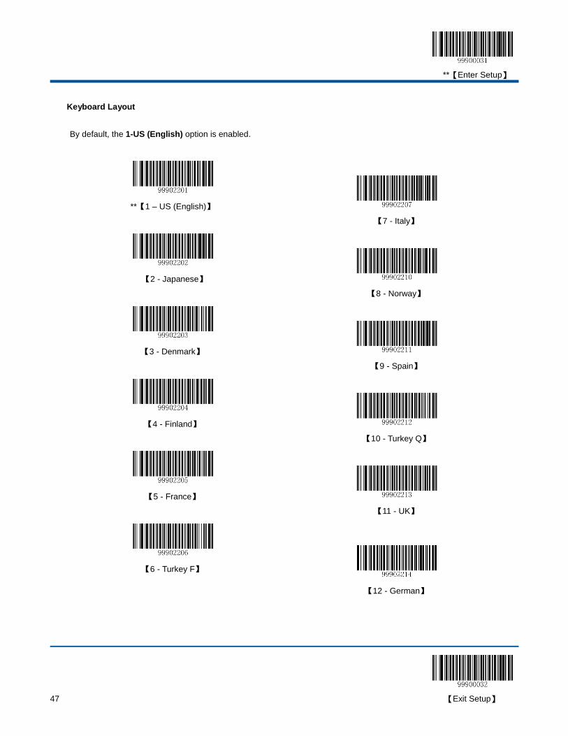
**【Enter Setup】
47 【Exit Setup】
Keyboard Layout
By default, the 1-US (English) option is enabled.
**【1 – US (English)】
【7 - Italy】
【2 - Japanese】
【8 - Norway】
【3 - Denmark】
【9 - Spain】
【4 - Finland】
【10 - Turkey Q】
【5 - France】
【11 - UK】
【6 - Turkey F】
【12 - German】
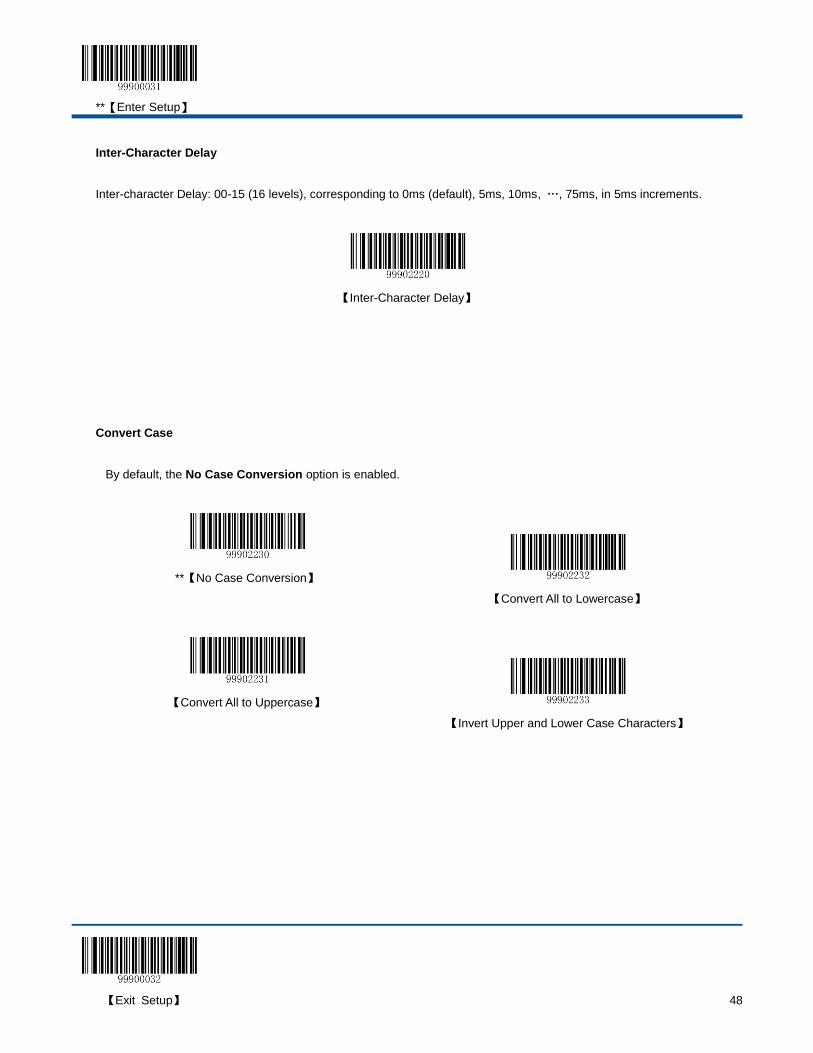
**【Enter Setup】
【Exit Setup】 48
Inter-Character Delay
Inter-character Delay: 00-15 (16 levels), corresponding to 0ms (default), 5ms, 10ms, …, 75ms, in 5ms increments.
【Inter-Character Delay】
Convert Case
By default, the No Case Conversion option is enabled.
**【No Case Conversion】
【Convert All to Lowercase】
【Convert All to Uppercase】
【Invert Upper and Lower Case Characters】
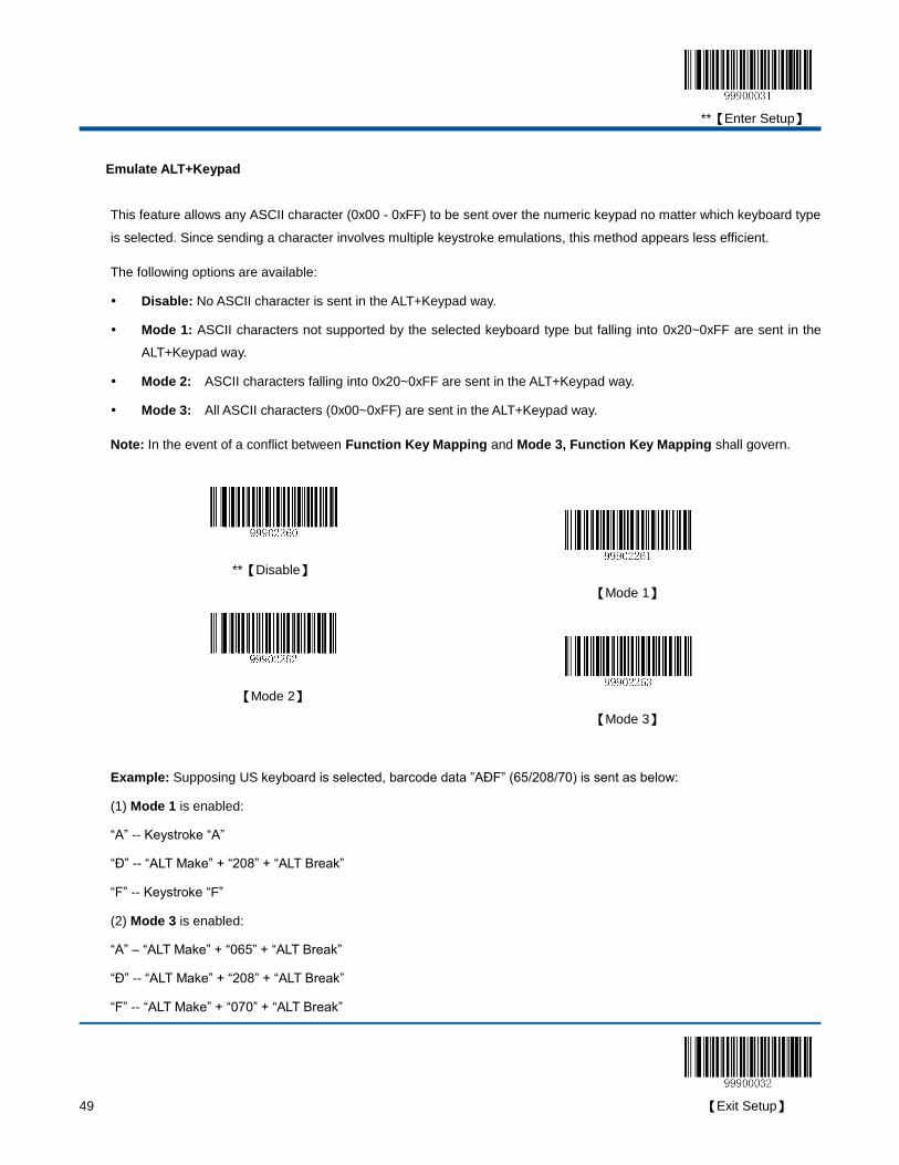
**【Enter Setup】
49 【Exit Setup】
Emulate ALT+Keypad
This feature allows any ASCII character (0x00 - 0xFF) to be sent over the numeric keypad no matter which keyboard type
is selected. Since sending a character involves multiple keystroke emulations, this method appears less efficient.
The following options are available:
Disable: No ASCII character is sent in the ALT+Keypad way.
Mode 1: ASCII characters not supported by the selected keyboard type but falling into 0x20~0xFF are sent in the
ALT+Keypad way.
Mode 2: ASCII characters falling into 0x20~0xFF are sent in the ALT+Keypad way.
Mode 3: All ASCII characters (0x00~0xFF) are sent in the ALT+Keypad way.
Note: In the event of a conflict between Function Key Mapping and Mode 3, Function Key Mapping shall govern.
**【Disable】
【Mode 1】
【Mode 2】
【Mode 3】
Example: Supposing US keyboard is selected, barcode data ”AÐF” (65/208/70) is sent as below:
(1) Mode 1 is enabled:
“A” -- Keystroke “A”
“Д -- “ALT Make” + “208” + “ALT Break”
“F” -- Keystroke “F”
(2) Mode 3 is enabled:
“A” – “ALT Make” + “065” + “ALT Break”
“Д -- “ALT Make” + “208” + “ALT Break”
“F” -- “ALT Make” + “070” + “ALT Break”
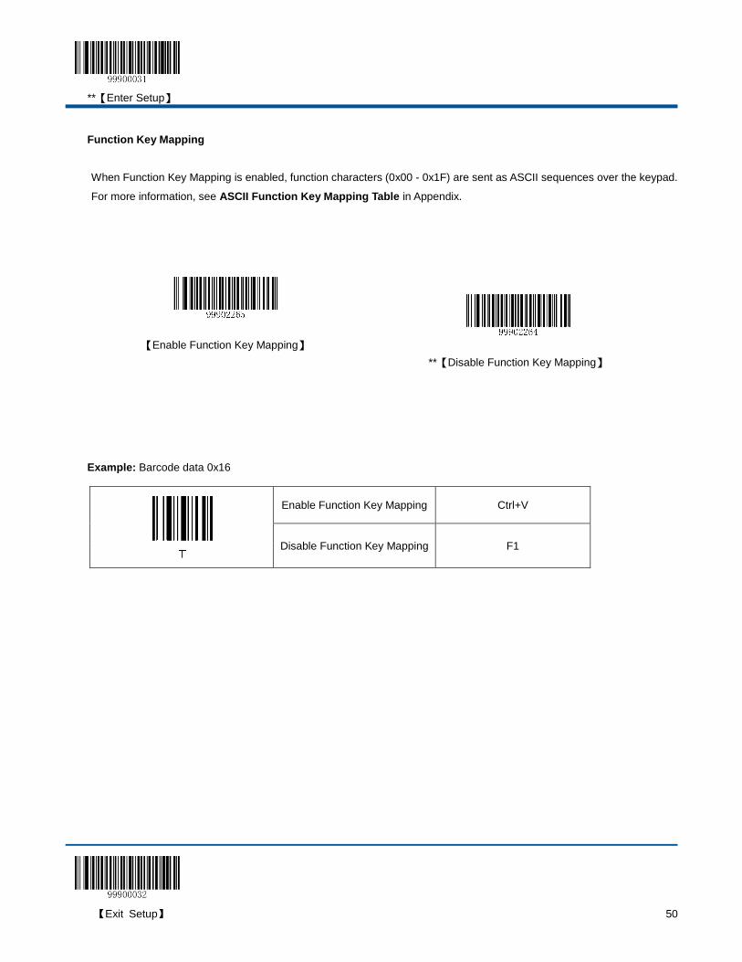
**【Enter Setup】
【Exit Setup】 50
Function Key Mapping
When Function Key Mapping is enabled, function characters (0x00 - 0x1F) are sent as ASCII sequences over the keypad.
For more information, see ASCII Function Key Mapping Table in Appendix.
Example: Barcode data 0x16
Enable Function Key Mapping Ctrl+V
Disable Function Key Mapping F1
【Enable Function Key Mapping】
**【Disable Function Key Mapping】
**【Enter Setup】
51 【Exit Setup】
Emulate Numeric Keypad
When this feature is disabled, sending barcode data is emulated as keystroke(s) on main keyboard.
To enable this feature, scan the Emulate Numeric Keypad barcode. Sending a number (0-9) is emulated as keystroke(s) on
numeric keypad, whereas sending other character like “+”, “_”, “*” , “/” and “.” is still emulated as keystrokes on main
keyboard.
**【Do Not Emulate Numeric Keypad】
【Emulate Numeric Keypad】
**【Enter Setup】
【Exit Setup】 52
USB COM Port Emulation
【USB COM Port Emulation】
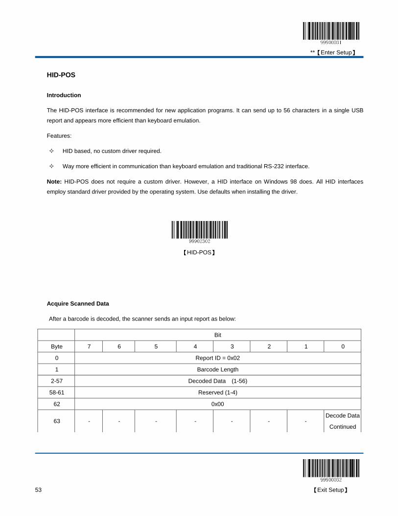
**【Enter Setup】
53 【Exit Setup】
HID-POS
Introduction
The HID-POS interface is recommended for new application programs. It can send up to 56 characters in a single USB
report and appears more efficient than keyboard emulation.
Features:
HID based, no custom driver required.
Way more efficient in communication than keyboard emulation and traditional RS-232 interface.
Note: HID-POS does not require a custom driver. However, a HID interface on Windows 98 does. All HID interfaces
employ standard driver provided by the operating system. Use defaults when installing the driver.
【HID-POS】
Acquire Scanned Data
After a barcode is decoded, the scanner sends an input report as below:
Bit
Byte 7 6 5 4 3 2 1 0
0 Report ID = 0x02
1 Barcode Length
2-57 Decoded Data (1-56)
58-61 Reserved (1-4)
62 0x00
63 - - - - - - - Decode Data
Continued

**【Enter Setup】
【Exit Setup】 54
VID/PID
USB uses VID (Vendor ID) and PID (Product ID) to identify and locate a device. The VID is assigned by USB
Implementers Forum. Newland’s vendor ID is 1EAB (Hex). A range of PIDs are used for each Newland product family.
Every PID contains a base number and interface type (keyboard, COM port, etc.).
Product Interface PID (Hex) PID (Dec)
HR15
USB HID-KBW 1403 5123
USB COM Port 1402 5122
HID-POS 1410 5136
**【Enter Setup】
55 【Exit Setup】
Chapter 5 Data Formatting
Introduction
After a successful barcode reading, a string containing numbers, letters or symbols will be returned.
In real applications, barcode data may be found insufficient for your needs. You may wish to include additional information
such as barcode type, data acquisition time or delimiter in data being scanned.
Adding extra information to printed barcodes does not seem like a sensible solution since that will increase the barcode
size and make them inflexible. Instead, we come up with the idea of appending prefix and suffix to the data without making
any change to barcodes. We will show you how to conduct the configuration in the following sections.
Note: Customized data: <Prefix> <Data><Suffix><Terminating Character>
Prefix Sequence
By default, the Code ID+Custom+AIM ID option is enabled.
**【Code ID+Custom+AIM ID】
【Custom+Code ID+AIM ID】
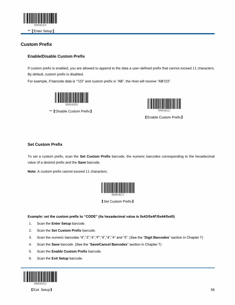
**【Enter Setup】
【Exit Setup】 56
Custom Prefix
Enable/Disable Custom Prefix
If custom prefix is enabled, you are allowed to append to the data a user-defined prefix that cannot exceed 11 characters.
By default, custom prefix is disabled.
For example, if barcode data is “123” and custom prefix is “AB”, the Host will receive “AB123”.
**【Disable Custom Prefix】
【Enable Custom Prefix】
Set Custom Prefix
To set a custom prefix, scan the Set Custom Prefix barcode, the numeric barcodes corresponding to the hexadecimal
value of a desired prefix and the Save barcode.
Note: A custom prefix cannot exceed 11 characters.
【Set Custom Prefix】
Example: set the custom prefix to “CODE” (its hexadecimal value is 0x43/0x4F/0x44/0x45)
1. Scan the Enter Setup barcode.
2. Scan the Set Custom Prefix barcode.
3. Scan the numeric barcodes “4”,“3”,“4”,“F”,“4”,“4”,“4” and “5”. (See the “Digit Barcodes” section in Chapter 7)
4. Scan the Save barcode. (See the “Save/Cancel Barcodes” section in Chapter 7)
5. Scan the Enable Custom Prefix barcode.
6. Scan the Exit Setup barcode.
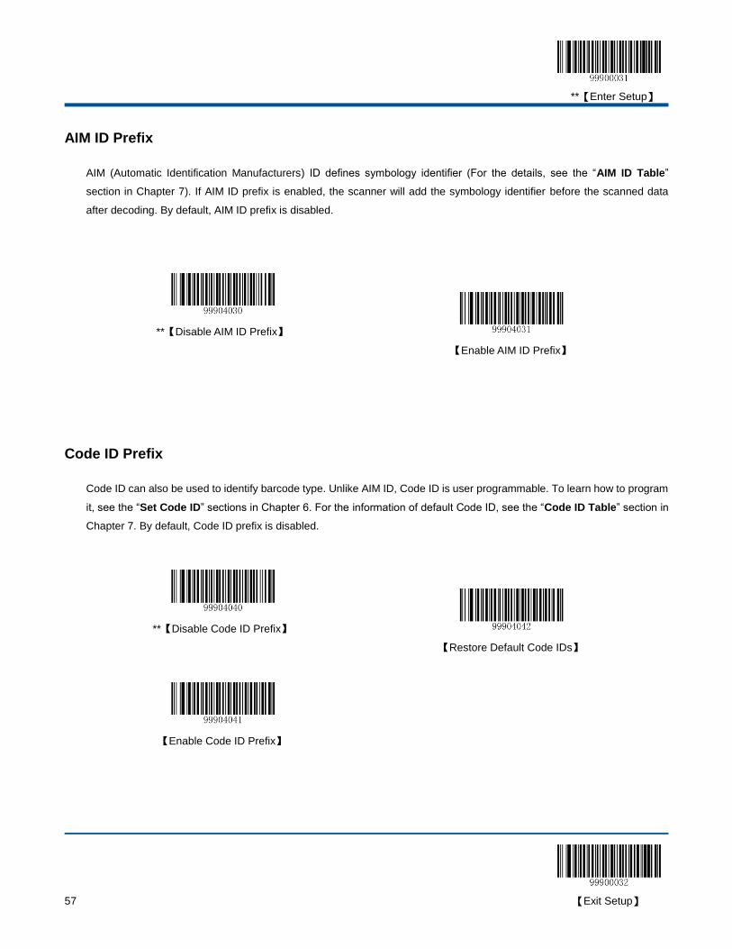
**【Enter Setup】
57 【Exit Setup】
AIM ID Prefix
AIM (Automatic Identification Manufacturers) ID defines symbology identifier (For the details, see the “AIM ID Table”
section in Chapter 7). If AIM ID prefix is enabled, the scanner will add the symbology identifier before the scanned data
after decoding. By default, AIM ID prefix is disabled.
**【Disable AIM ID Prefix】
【Enable AIM ID Prefix】
Code ID Prefix
Code ID can also be used to identify barcode type. Unlike AIM ID, Code ID is user programmable. To learn how to program
it, see the “Set Code ID” sections in Chapter 6. For the information of default Code ID, see the “Code ID Table” section in
Chapter 7. By default, Code ID prefix is disabled.
**【Disable Code ID Prefix】
【Restore Default Code IDs】
【Enable Code ID Prefix】
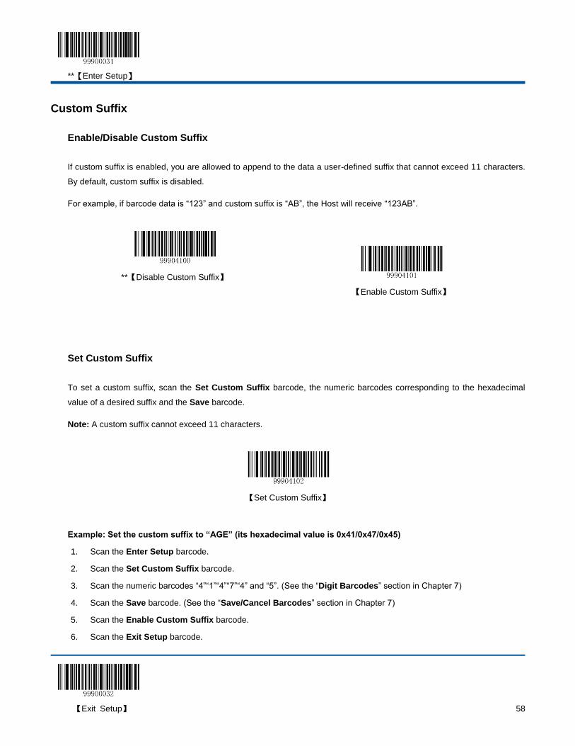
**【Enter Setup】
【Exit Setup】 58
Custom Suffix
Enable/Disable Custom Suffix
If custom suffix is enabled, you are allowed to append to the data a user-defined suffix that cannot exceed 11 characters.
By default, custom suffix is disabled.
For example, if barcode data is “123” and custom suffix is “AB”, the Host will receive “123AB”.
**【Disable Custom Suffix】
【Enable Custom Suffix】
Set Custom Suffix
To set a custom suffix, scan the Set Custom Suffix barcode, the numeric barcodes corresponding to the hexadecimal
value of a desired suffix and the Save barcode.
Note: A custom suffix cannot exceed 11 characters.
【Set Custom Suffix】
Example: Set the custom suffix to “AGE” (its hexadecimal value is 0x41/0x47/0x45)
1. Scan the Enter Setup barcode.
2. Scan the Set Custom Suffix barcode.
3. Scan the numeric barcodes “4”“1”“4”“7”“4” and “5”. (See the “Digit Barcodes” section in Chapter 7)
4. Scan the Save barcode. (See the “Save/Cancel Barcodes” section in Chapter 7)
5. Scan the Enable Custom Suffix barcode.
6. Scan the Exit Setup barcode.
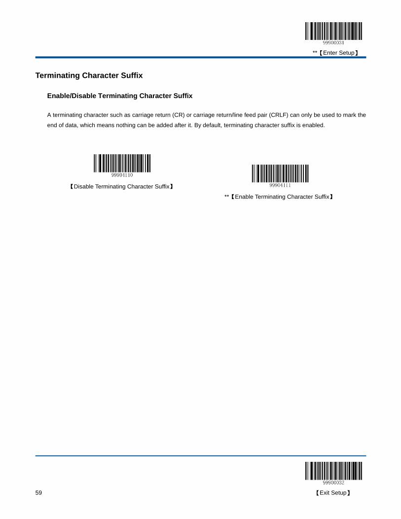
**【Enter Setup】
59 【Exit Setup】
Terminating Character Suffix
Enable/Disable Terminating Character Suffix
A terminating character such as carriage return (CR) or carriage return/line feed pair (CRLF) can only be used to mark the
end of data, which means nothing can be added after it. By default, terminating character suffix is enabled.
【Disable Terminating Character Suffix】
**【Enable Terminating Character Suffix】
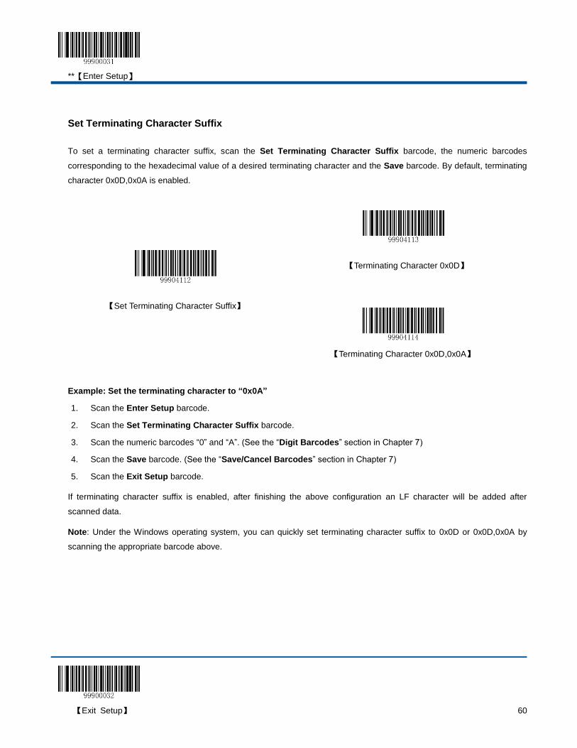
**【Enter Setup】
【Exit Setup】 60
Set Terminating Character Suffix
To set a terminating character suffix, scan the Set Terminating Character Suffix barcode, the numeric barcodes
corresponding to the hexadecimal value of a desired terminating character and the Save barcode. By default, terminating
character 0x0D,0x0A is enabled.
【Set Terminating Character Suffix】
【Terminating Character 0x0D】
【Terminating Character 0x0D,0x0A】
Example: Set the terminating character to “0x0A”
1. Scan the Enter Setup barcode.
2. Scan the Set Terminating Character Suffix barcode.
3. Scan the numeric barcodes “0” and “A”. (See the “Digit Barcodes” section in Chapter 7)
4. Scan the Save barcode. (See the “Save/Cancel Barcodes” section in Chapter 7)
5. Scan the Exit Setup barcode.
If terminating character suffix is enabled, after finishing the above configuration an LF character will be added after
scanned data.
Note: Under the Windows operating system, you can quickly set terminating character suffix to 0x0D or 0x0D,0x0A by
scanning the appropriate barcode above.
**【Enter Setup】
61 【Exit Setup】
Chapter 6 Symbologies
Introduction
Every symbology (barcode type) has its own unique attributes. This chapter provides programming barcodes for
configuring the scanner so that it can identify various barcode symbologies. It is recommended to disable those that are
rarely used to increase the efficiency of the scanner.
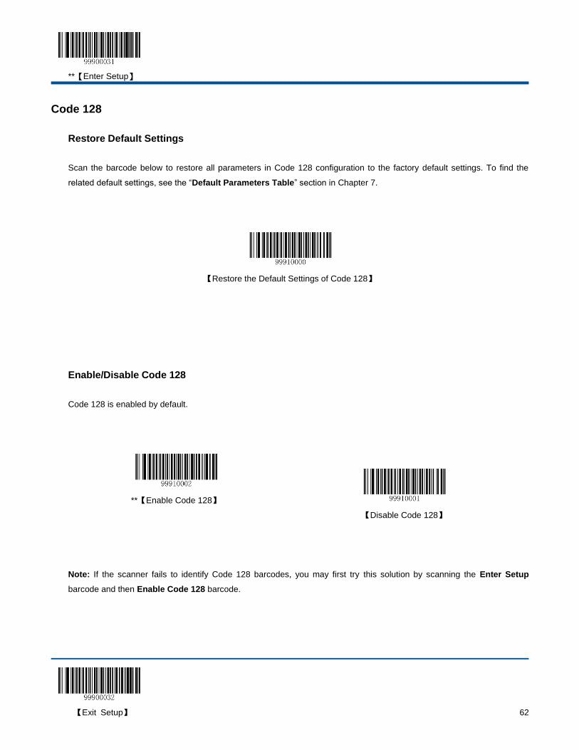
**【Enter Setup】
【Exit Setup】 62
Code 128
Restore Default Settings
Scan the barcode below to restore all parameters in Code 128 configuration to the factory default settings. To find the
related default settings, see the “Default Parameters Table” section in Chapter 7.
【Restore the Default Settings of Code 128】
Enable/Disable Code 128
Code 128 is enabled by default.
**【Enable Code 128】
【Disable Code 128】
Note: If the scanner fails to identify Code 128 barcodes, you may first try this solution by scanning the Enter Setup
barcode and then Enable Code 128 barcode.
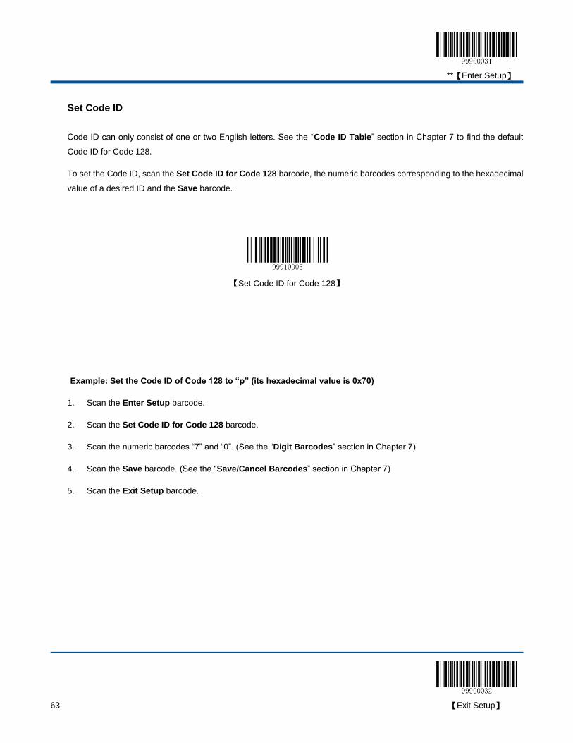
**【Enter Setup】
63 【Exit Setup】
Set Code ID
Code ID can only consist of one or two English letters. See the “Code ID Table” section in Chapter 7 to find the default
Code ID for Code 128.
To set the Code ID, scan the Set Code ID for Code 128 barcode, the numeric barcodes corresponding to the hexadecimal
value of a desired ID and the Save barcode.
【Set Code ID for Code 128】
Example: Set the Code ID of Code 128 to “p” (its hexadecimal value is 0x70)
1. Scan the Enter Setup barcode.
2. Scan the Set Code ID for Code 128 barcode.
3. Scan the numeric barcodes “7” and “0”. (See the “Digit Barcodes” section in Chapter 7)
4. Scan the Save barcode. (See the “Save/Cancel Barcodes” section in Chapter 7)
5. Scan the Exit Setup barcode.
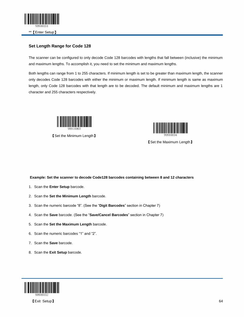
**【Enter Setup】
【Exit Setup】 64
Set Length Range for Code 128
The scanner can be configured to only decode Code 128 barcodes with lengths that fall between (inclusive) the minimum
and maximum lengths. To accomplish it, you need to set the minimum and maximum lengths.
Both lengths can range from 1 to 255 characters. If minimum length is set to be greater than maximum length, the scanner
only decodes Code 128 barcodes with either the minimum or maximum length. If minimum length is same as maximum
length, only Code 128 barcodes with that length are to be decoded. The default minimum and maximum lengths are 1
character and 255 characters respectively.
【Set the Minimum Length】
【Set the Maximum Length】
Example: Set the scanner to decode Code128 barcodes containing between 8 and 12 characters
1. Scan the Enter Setup barcode.
2. Scan the Set the Minimum Length barcode.
3. Scan the numeric barcode “8”. (See the “Digit Barcodes” section in Chapter 7)
4. Scan the Save barcode. (See the “Save/Cancel Barcodes” section in Chapter 7)
5. Scan the Set the Maximum Length barcode.
6. Scan the numeric barcodes “1” and “2”.
7. Scan the Save barcode.
8. Scan the Exit Setup barcode.

**【Enter Setup】
65 【Exit Setup】
UCC/EAN-128
Restore Default Settings
Scan the barcode below to restore all parameters in UCC/EAN-128 configuration to the factory default settings. To find the
related default settings, see the “Default Parameters Table” section in Chapter 7.
【Restore the Default Settings of UCC/EAN-128】
Enable/Disable UCC/EAN-128
UCC/EAN-128 is enabled by default.
**【Enable UCC/EAN-128】
【Disable UCC/EAN-128】
Note: If the scanner fails to identify UCC/EAN-128 barcodes, you may first try this solution by scanning the Enter Setup
barcode and then Enable UCC/EAN-128 barcode.
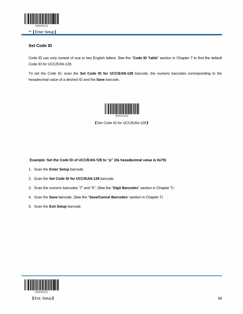
**【Enter Setup】
【Exit Setup】 66
Set Code ID
Code ID can only consist of one or two English letters. See the “Code ID Table” section in Chapter 7 to find the default
Code ID for UCC/EAN-128.
To set the Code ID, scan the Set Code ID for UCC/EAN-128 barcode, the numeric barcodes corresponding to the
hexadecimal value of a desired ID and the Save barcode.
【Set Code ID for UCC/EAN-128】
Example: Set the Code ID of UCC/EAN-128 to “p” (its hexadecimal value is 0x70)
1. Scan the Enter Setup barcode.
2. Scan the Set Code ID for UCC/EAN-128 barcode.
3. Scan the numeric barcodes “7” and “0”. (See the “Digit Barcodes” section in Chapter 7)
4. Scan the Save barcode. (See the “Save/Cancel Barcodes” section in Chapter 7)
5. Scan the Exit Setup barcode.
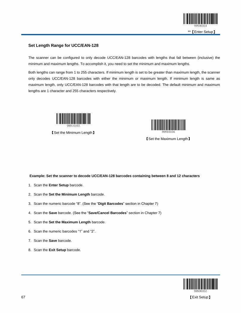
**【Enter Setup】
67 【Exit Setup】
Set Length Range for UCC/EAN-128
The scanner can be configured to only decode UCC/EAN-128 barcodes with lengths that fall between (inclusive) the
minimum and maximum lengths. To accomplish it, you need to set the minimum and maximum lengths.
Both lengths can range from 1 to 255 characters. If minimum length is set to be greater than maximum length, the scanner
only decodes UCC/EAN-128 barcodes with either the minimum or maximum length. If minimum length is same as
maximum length, only UCC/EAN-128 barcodes with that length are to be decoded. The default minimum and maximum
lengths are 1 character and 255 characters respectively.
【Set the Minimum Length】
【Set the Maximum Length】
Example: Set the scanner to decode UCC/EAN-128 barcodes containing between 8 and 12 characters
1. Scan the Enter Setup barcode.
2. Scan the Set the Minimum Length barcode.
3. Scan the numeric barcode “8”. (See the “Digit Barcodes” section in Chapter 7)
4. Scan the Save barcode. (See the “Save/Cancel Barcodes” section in Chapter 7)
5. Scan the Set the Maximum Length barcode.
6. Scan the numeric barcodes “1” and “2”.
7. Scan the Save barcode.
8. Scan the Exit Setup barcode.
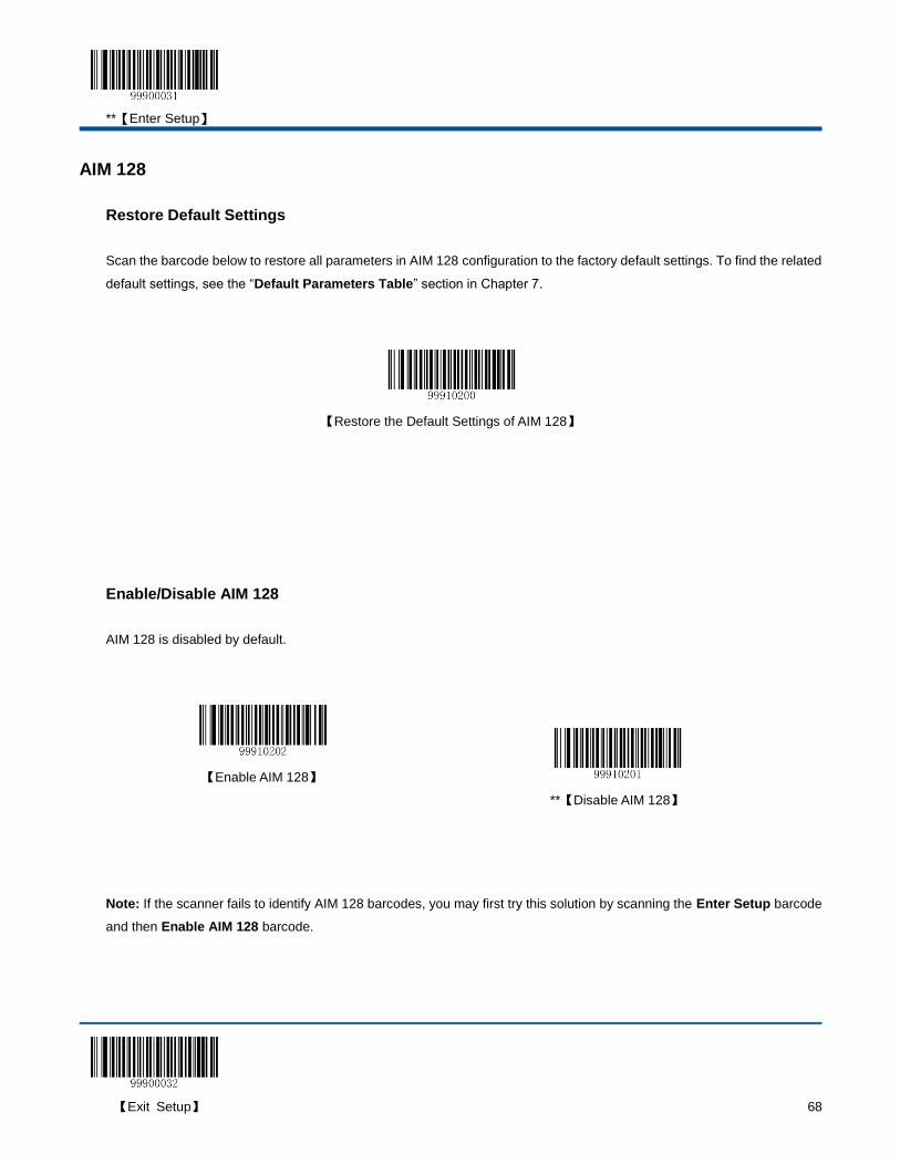
**【Enter Setup】
【Exit Setup】 68
AIM 128
Restore Default Settings
Scan the barcode below to restore all parameters in AIM 128 configuration to the factory default settings. To find the related
default settings, see the “Default Parameters Table” section in Chapter 7.
【Restore the Default Settings of AIM 128】
Enable/Disable AIM 128
AIM 128 is disabled by default.
【Enable AIM 128】
**【Disable AIM 128】
Note: If the scanner fails to identify AIM 128 barcodes, you may first try this solution by scanning the Enter Setup barcode
and then Enable AIM 128 barcode.
**【Enter Setup】
69 【Exit Setup】
Set Code ID
Code ID can only consist of one or two English letters. See the “Code ID Table” section in Chapter 7 to find the default
Code ID for AIM 128.
To set the Code ID, scan the Set Code ID for AIM 128 barcode, the numeric barcodes corresponding to the hexadecimal
value of a desired ID and the Save barcode.
【Set Code ID for AIM 128】
Example: Set the Code ID of AIM-128 to “p” (its hexadecimal value is 0x70)
1. Scan the Enter Setup barcode.
2. Scan the Set Code ID for AIM-128 barcode.
3. Scan the numeric barcodes “7” and “0”. (See the “Digit Barcodes” section in Chapter 7)
4. Scan the Save barcode. (See the “Save/Cancel Barcodes” section in Chapter 7)
5. Scan the Exit Setup barcode.

**【Enter Setup】
【Exit Setup】 70
Set Length Range for AIM 128
The scanner can be configured to only decode AIM 128 barcodes with lengths that fall between (inclusive) the minimum
and maximum lengths. To accomplish it, you need to set the minimum and maximum lengths.
Both lengths can range from 1 to 255 characters. If minimum length is set to be greater than maximum length, the scanner
only decodes AIM 128 barcodes with either the minimum or maximum length. If minimum length is same as maximum
length, only AIM 128 barcodes with that length are to be decoded. The default minimum and maximum lengths are 1
character and 255 characters respectively.
【Set the Maximum Length】
【Set the Minimum Length】
Example: Set the scanner to decode AIM128 barcodes containing between 8 and 12 characters
1. Scan the Enter Setup barcode.
2. Scan the Set the Minimum Length barcode.
3. Scan the numeric barcode “8”. (See the “Digit Barcodes” section in Chapter 7)
4. Scan the Save barcode. (See the “Save/Cancel Barcodes” section in Chapter 7)
5. Scan the Set the Maximum Length barcode.
6. Scan the numeric barcodes “1” and “2”.
7. Scan the Save barcode.
8. Scan the Exit Setup barcode.
**【Enter Setup】
71 【Exit Setup】
EAN-8
Restore Default Settings
Scan the barcode below to restore all parameters in EAN-8 configuration to the factory default settings. To find the related
default settings, see the “Default Parameters Table” section in Chapter 7.
【Restore the Default Settings of EAN-8】
Enable/Disable EAN-8
EAN-8 is enabled by default.
**【Enable EAN-8】
【Disable EAN-8】
Note: If the scanner fails to identify EAN-8 barcodes, you may first try this solution by scanning the Enter Setup barcode
and then Enable EAN-8 barcode.
**【Enter Setup】
【Exit Setup】 72
Set Code ID
Code ID can only consist of one or two English letters. See the “Code ID Table” section in Chapter 7 to find the default
Code ID for EAN-8.
To set the Code ID, scan the Set Code ID for EAN-8 barcode, the numeric barcodes corresponding to the hexadecimal
value of a desired ID and the Save barcode.
【Set Code ID for EAN-8】
Example: Set the Code ID of EAN-8 to “p” (its hexadecimal value is 0x70)
1. Scan the Enter Setup barcode.
2. Scan the Set Code ID for EAN-8 barcode.
3. Scan the numeric barcodes “7” and “0”. (See the “Digit Barcodes” section in Chapter 7)
4. Scan the Save barcode. (See the “Save/Cancel Barcodes” section in Chapter 7)
5. Scan the Exit Setup barcode.

**【Enter Setup】
73 【Exit Setup】
2-Digit Add-On Code
An EAN-8 barcode can be augmented with a two-digit add-on code to form a new one..
**【Disable 2-Digit Add-On Code】
【Enable 2-Digit Add-On Code】
【Decode EAN-8 + 2-Digit Add-On Code Only】
Note:
Disable 2-Digit Add-On Code: The scanner decodes EAN-8 and ignores the add-on code when presented with an
EAN-8 plus 2-digit add-on barcode. It can also decode EAN-8 barcodes without 2-digit add-on codes.
Enable 2-Digit Add-On Code: The scanner decodes a mix of EAN-8 barcodes with and without 2-digit add-on
codes.
Decode EAN-8 + 2-Digit Add-On Code Only: The scanner only decodes EAN-8 barcodes that contain 2-digit
add-on codes.

**【Enter Setup】
【Exit Setup】 74
5-Digit Add-On Code
An EAN-8 barcode can be augmented with a five-digit add-on code to form a new one.
**【Disable 5-Digit Add-On Code】
【Enable 5-Digit Add-On Code】
【Decode EAN-8 + 5-Digit Add-On Code Only】
Note:
Disable 5-Digit Add-On Code: The scanner decodes EAN-8 and ignores the add-on code when presented with an
EAN-8 plus 5-digit add-on barcode. It can also decode EAN-8 barcodes without 5-digit add-on codes.
Enable 5-Digit Add-On Code: The scanner decodes a mix of EAN-8 barcodes with and without 5-digit add-on
codes.
Decode EAN-8 + 5-Digit Add-On Code Only: The scanner only decodes EAN-8 barcodes that contain 5-digit
add-on codes.
**【Enter Setup】
75 【Exit Setup】
EAN-8 Extension
Disable EAN-8 Zero Extend: Transmit EAN-8 barcodes as is.
Enable EAN-8 Zero Extend: Add five leading zeros to decoded EAN-8 barcodes to extend to13 digits.
Convert EAN-8 to EAN-13: Add five leading zeros to decoded EAN-8 barcodes to make them compatible in format
to EAN-13 barcodes.
**【Disable EAN-8 Zero Extend】
【Enable EAN-8 Zero Extend】
【Convert EAN-8 to EAN-13】
Transmit Check Digit
EAN-8 is 8 digits in length with the last one as its check digit used to verify the integrity of the data. By default, the scanner
transmits EAN-8 check digit.
**【Transmit EAN-8 Check Digit】
【Do Not Transmit EAN-8 Check Digit】
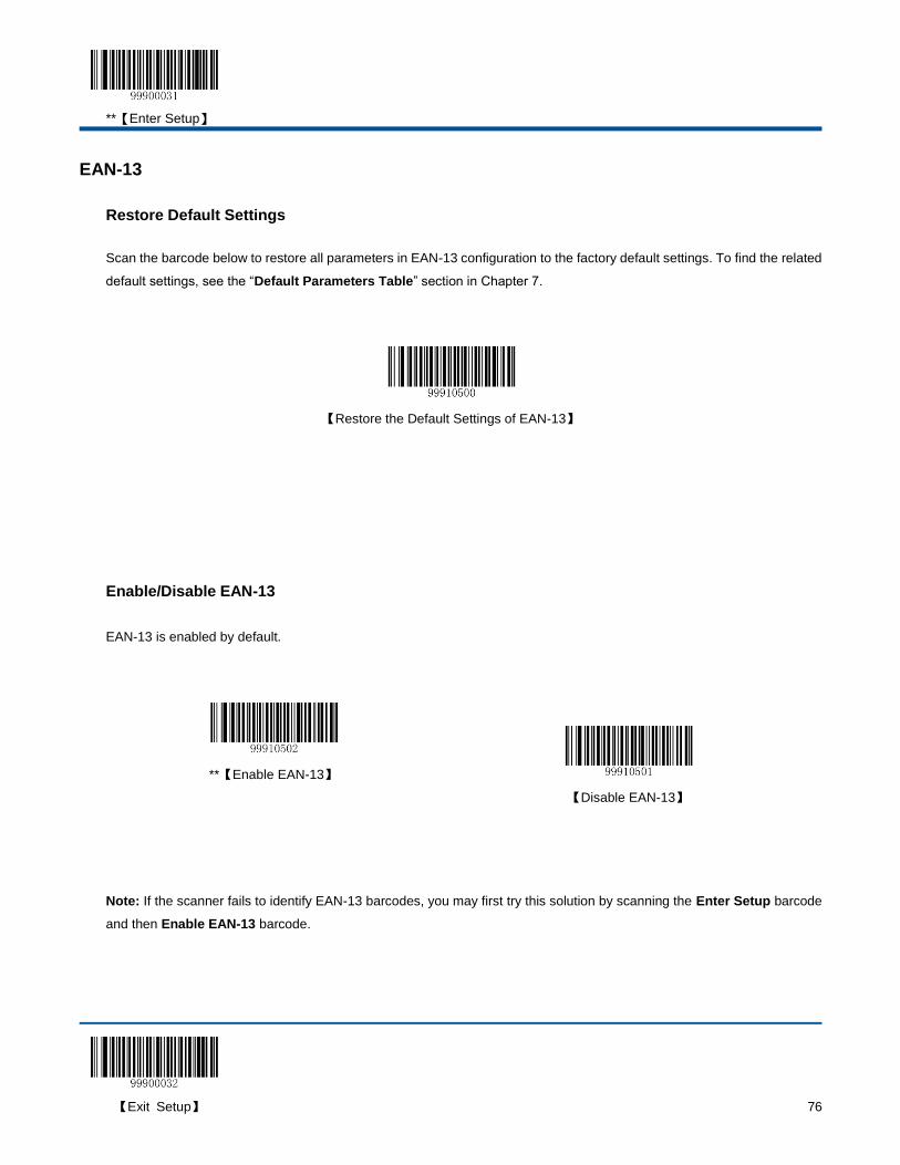
**【Enter Setup】
【Exit Setup】 76
EAN-13
Restore Default Settings
Scan the barcode below to restore all parameters in EAN-13 configuration to the factory default settings. To find the related
default settings, see the “Default Parameters Table” section in Chapter 7.
【Restore the Default Settings of EAN-13】
Enable/Disable EAN-13
EAN-13 is enabled by default.
**【Enable EAN-13】
【Disable EAN-13】
Note: If the scanner fails to identify EAN-13 barcodes, you may first try this solution by scanning the Enter Setup barcode
and then Enable EAN-13 barcode.

**【Enter Setup】
77 【Exit Setup】
Transmit Check Digit
EAN-13 is 13 digits in length with the last one as its check digit used to verify the integrity of the data. By default, the
scanner transmits EAN-13 check digit.
**【Transmit EAN-13 Check Digit】
【Do Not Transmit EAN-13 Check Digit】
Set Code ID
Code ID can only consist of one or two English letters. See the “Code ID Table” section in Chapter 7 to find the default
Code ID for EAN-13.
To set the Code ID, scan the Set Code ID for EAN-13 barcode, the numeric barcodes corresponding to the hexadecimal
value of a desired ID and the Save barcode.
【Set Code ID for EAN-13】
Example: Set the Code ID of EAN-13 to “p” (its hexadecimal value is 0x70)
1. Scan the Enter Setup barcode.
2. Scan the Set Code ID for EAN-13 barcode.
3. Scan the numeric barcodes “7” and “0”. (See the “Digit Barcodes” section in Chapter 7)
4. Scan the Save barcode. (See the “Save/Cancel Barcodes” section in Chapter 7)
5. Scan the Exit Setup barcode.
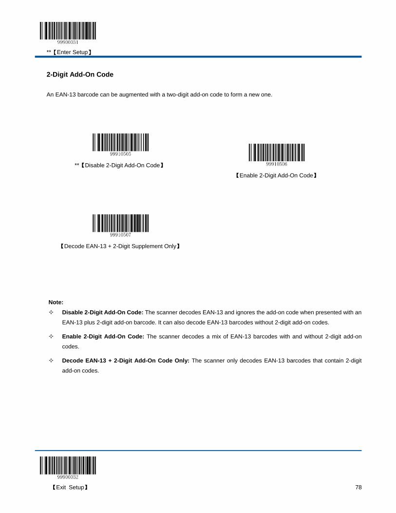
**【Enter Setup】
【Exit Setup】 78
2-Digit Add-On Code
An EAN-13 barcode can be augmented with a two-digit add-on code to form a new one.
**【Disable 2-Digit Add-On Code】
【Enable 2-Digit Add-On Code】
【Decode EAN-13 + 2-Digit Supplement Only】
Note:
Disable 2-Digit Add-On Code: The scanner decodes EAN-13 and ignores the add-on code when presented with an
EAN-13 plus 2-digit add-on barcode. It can also decode EAN-13 barcodes without 2-digit add-on codes.
Enable 2-Digit Add-On Code: The scanner decodes a mix of EAN-13 barcodes with and without 2-digit add-on
codes.
Decode EAN-13 + 2-Digit Add-On Code Only: The scanner only decodes EAN-13 barcodes that contain 2-digit
add-on codes.
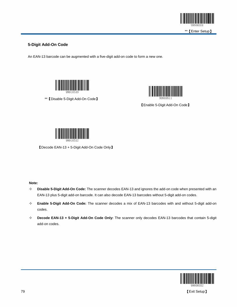
**【Enter Setup】
79 【Exit Setup】
5-Digit Add-On Code
An EAN-13 barcode can be augmented with a five-digit add-on code to form a new one.
**【Disable 5-Digit Add-On Code】
【Enable 5-Digit Add-On Code】
【Decode EAN-13 + 5-Digit Add-On Code Only】
Note:
Disable 5-Digit Add-On Code: The scanner decodes EAN-13 and ignores the add-on code when presented with an
EAN-13 plus 5-digit add-on barcode. It can also decode EAN-13 barcodes without 5-digit add-on codes.
Enable 5-Digit Add-On Code: The scanner decodes a mix of EAN-13 barcodes with and without 5-digit add-on
codes.
Decode EAN-13 + 5-Digit Add-On Code Only: The scanner only decodes EAN-13 barcodes that contain 5-digit
add-on codes.
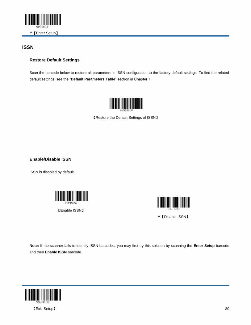
**【Enter Setup】
【Exit Setup】 80
ISSN
Restore Default Settings
Scan the barcode below to restore all parameters in ISSN configuration to the factory default settings. To find the related
default settings, see the “Default Parameters Table” section in Chapter 7.
【Restore the Default Settings of ISSN】
Enable/Disable ISSN
ISSN is disabled by default.
【Enable ISSN】
**【Disable ISSN】
Note: If the scanner fails to identify ISSN barcodes, you may first try this solution by scanning the Enter Setup barcode
and then Enable ISSN barcode.
**【Enter Setup】
81 【Exit Setup】
Set Code ID
Code ID can only consist of one or two English letters. See the “Code ID Table” section in Chapter 7 to find the default
Code ID for ISSN.
To set the Code ID, scan the Set Code ID for ISSN barcode, the numeric barcodes corresponding to the hexadecimal
value of a desired ID and the Save barcode.
【Set Code ID for ISSN】
Example: Set the Code ID of ISSN to “p” (its hexadecimal value is 0x70)
1. Scan the Enter Setup barcode.
2. Scan the Set Code ID for ISSN barcode.
3. Scan the numeric barcodes “7” and “0”. (See the “Digit Barcodes” section in Chapter 7)
4. Scan the Save barcode. (See the “Save/Cancel Barcodes” section in Chapter 7)
5. Scan the Exit Setup barcode.

**【Enter Setup】
【Exit Setup】 82
ISBN
Restore Default Settings
Scan the barcode below to restore all parameters in ISBN configuration to the factory default settings. To find the related
default settings, see the “Default Parameters Table” section in Chapter 7.
【Restore the Default Settings of ISBN】
Enable/Disable ISBN
ISBN is disabled by default.
【Enable ISBN】
**【Disable ISBN】
Note: If the scanner fails to identify ISBN barcodes, you may first try this solution by scanning the Enter Setup barcode
and then Enable ISBN barcode.
**【Enter Setup】
83 【Exit Setup】
Set ISBN Format
The default format is ISBN-13.
**【ISBN-13】
【ISBN-10】
Set Code ID
Code ID can only consist of one or two English letters. See the “Code ID Table” section in Chapter 7 to find the default
Code ID for ISBN.
To set the Code ID, scan the Set Code ID for ISBN barcode, the numeric barcodes corresponding to the hexadecimal
value of a desired ID and the Save barcode.
【Set Code ID for ISBN】
Example: Set the Code ID of ISBN to “p” (its hexadecimal value is 0x70)
1. Scan the Enter Setup barcode.
2. Scan the Set Code ID for ISBN barcode.
3. Scan the numeric barcodes “7” and “0”. (See the “Digit Barcodes” section in Chapter 7)
4. Scan the Save barcode. (See the “Save/Cancel Barcodes” section in Chapter 7)
5. Scan the Exit Setup barcode.
**【Enter Setup】
【Exit Setup】 84
UPC-E
Restore Default Settings
Scan the barcode below to restore all parameters in UPC-E configuration to the factory default settings. To find the related
default settings, see the “Default Parameters Table” section in Chapter 7.
【Restore the Default Settings of UPC-E】
Enable/Disable UPC-E
UPC-E is enabled by default.
**【Enable UPC-E】
【Disable UPC-E】
Note: If the scanner fails to identify UPC-E barcodes, you may first try this solution by scanning the Enter Setup barcode
and then Enable UPC-E barcode.
**【Enter Setup】
85 【Exit Setup】
Transmit Check Digit
UPC-E is 8 digits in length with the last one as its check digit used to verify the integrity of the data. By default, the scanner
transmits UPC-E check digit.
**【Transmit UPC-E Check Digit】
【Do Not Transmit UPC-E Check Digit】
Set Code ID
Code ID can only consist of one or two English letters. See the “Code ID Table” section in Chapter 7 to find the default
Code ID for UPC-E.
To set the Code ID, scan the Set Code ID for UPC-E barcode, the numeric barcodes corresponding to the hexadecimal
value of a desired ID and the Save barcode.
【Set Code ID for UPC-E】
Example: Set the Code ID of UPC-E to “p” (its hexadecimal value is 0x70)
1. Scan the Enter Setup barcode.
2. Scan the Set Code ID for UPC-E barcode.
3. Scan the numeric barcodes “7” and “0”. (See the “Digit Barcodes” section in Chapter 7)
4. Scan the Save barcode. (See the “Save/Cancel Barcodes” section in Chapter 7)
5. Scan the Exit Setup barcode.
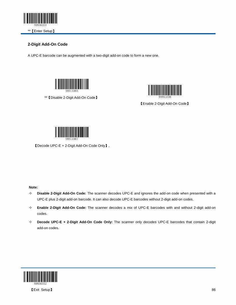
**【Enter Setup】
【Exit Setup】 86
2-Digit Add-On Code
A UPC-E barcode can be augmented with a two-digit add-on code to form a new one.
**【Disable 2-Digit Add-On Code】
【Enable 2-Digit Add-On Code】
【Decode UPC-E + 2-Digit Add-On Code Only】,
Note:
Disable 2-Digit Add-On Code: The scanner decodes UPC-E and ignores the add-on code when presented with a
UPC-E plus 2-digit add-on barcode. It can also decode UPC-E barcodes without 2-digit add-on codes.
Enable 2-Digit Add-On Code: The scanner decodes a mix of UPC-E barcodes with and without 2-digit add-on
codes.
Decode UPC-E + 2-Digit Add-On Code Only: The scanner only decodes UPC-E barcodes that contain 2-digit
add-on codes.
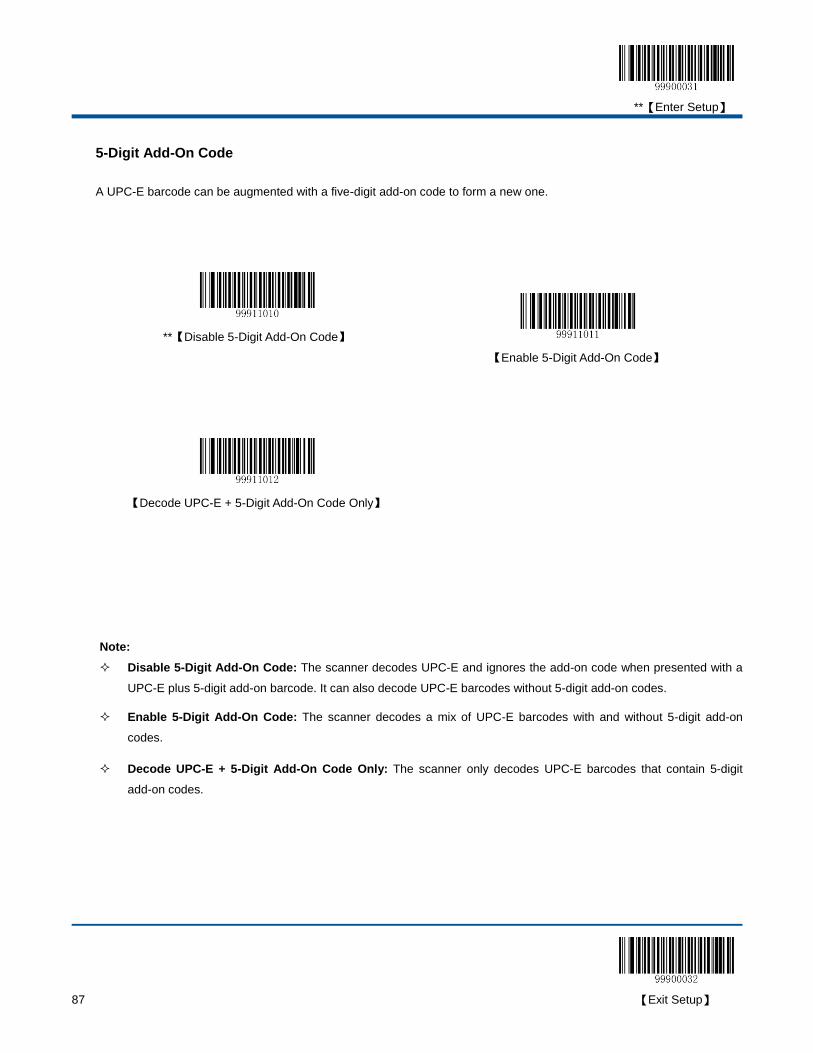
**【Enter Setup】
87 【Exit Setup】
5-Digit Add-On Code
A UPC-E barcode can be augmented with a five-digit add-on code to form a new one.
**【Disable 5-Digit Add-On Code】
【Enable 5-Digit Add-On Code】
【Decode UPC-E + 5-Digit Add-On Code Only】
Note:
Disable 5-Digit Add-On Code: The scanner decodes UPC-E and ignores the add-on code when presented with a
UPC-E plus 5-digit add-on barcode. It can also decode UPC-E barcodes without 5-digit add-on codes.
Enable 5-Digit Add-On Code: The scanner decodes a mix of UPC-E barcodes with and without 5-digit add-on
codes.
Decode UPC-E + 5-Digit Add-On Code Only: The scanner only decodes UPC-E barcodes that contain 5-digit
add-on codes.

**【Enter Setup】
【Exit Setup】 88
Transmit System Character “0”
The first character of UPC-E barcode is the system character “0”. By default, the scanner does not transmit system
character “0”.
**【Do Not Transmit System Character “0”】
【Transmit System Character “0”】
UPC-E Extension
Disable UPC-E Extend: Transmit UPC-E barcodes as is.
Enable UPC-E Extend: Extend UPC-E barcodes to make them compatible in length to UPC-A.
Convert UPC-E to UPC-A: Extend UPC-E barcodes to make them compatible in format to UPC-A.
**【Disable UPC-E Extend】
【Enable UPC-E Extend】
【Convert UPC-E to UPC-A】
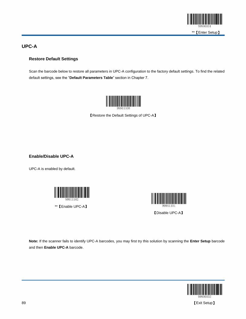
**【Enter Setup】
89 【Exit Setup】
UPC-A
Restore Default Settings
Scan the barcode below to restore all parameters in UPC-A configuration to the factory default settings. To find the related
default settings, see the “Default Parameters Table” section in Chapter 7.
【Restore the Default Settings of UPC-A】
Enable/Disable UPC-A
UPC-A is enabled by default.
**【Enable UPC-A】
【Disable UPC-A】
Note: If the scanner fails to identify UPC-A barcodes, you may first try this solution by scanning the Enter Setup barcode
and then Enable UPC-A barcode.
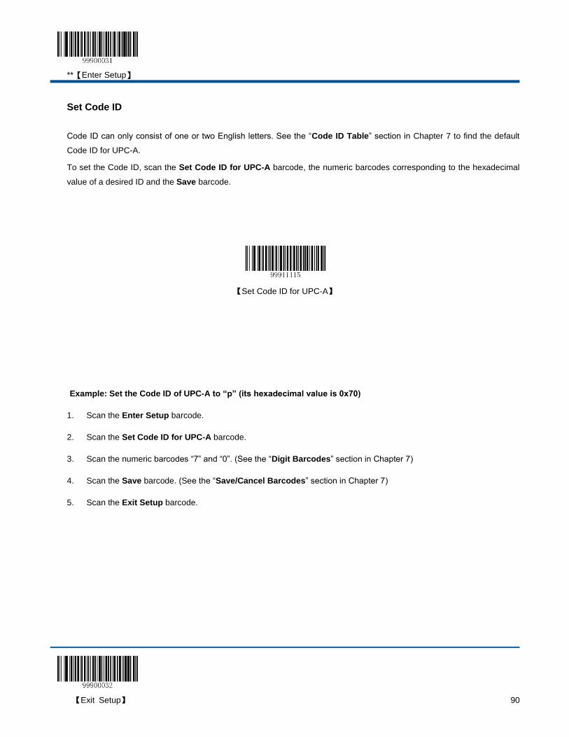
**【Enter Setup】
【Exit Setup】 90
Set Code ID
Code ID can only consist of one or two English letters. See the “Code ID Table” section in Chapter 7 to find the default
Code ID for UPC-A.
To set the Code ID, scan the Set Code ID for UPC-A barcode, the numeric barcodes corresponding to the hexadecimal
value of a desired ID and the Save barcode.
【Set Code ID for UPC-A】
Example: Set the Code ID of UPC-A to “p” (its hexadecimal value is 0x70)
1. Scan the Enter Setup barcode.
2. Scan the Set Code ID for UPC-A barcode.
3. Scan the numeric barcodes “7” and “0”. (See the “Digit Barcodes” section in Chapter 7)
4. Scan the Save barcode. (See the “Save/Cancel Barcodes” section in Chapter 7)
5. Scan the Exit Setup barcode.
**【Enter Setup】
91 【Exit Setup】
Transmit Check Digit
UPC-A is 13 digits in length with the last one as its check digit used to verify the integrity of the data. By default, the
scanner transmits UPC-A check digit.
**【Transmit UPC-A Check Digit】
【Do Not Transmit UPC-A Check Digit】
Transmit Preamble Character “0”
The first character of UPC-A barcode is the preamble character “0”. By default, the scanner does not transmit preamble
character “0”.
**【Do not Transmit Preamble Character “0” 】
【Transmit Preamble Character “0” 】
**【Enter Setup】
【Exit Setup】 92
2-Digit Add-On Code
A UPC-A barcode can be augmented with a two-digit add-on code to form a new one.
**【Disable 2-Digit Add-On Code】
【Enable 2-Digit Add-On Code】
【Decode UPC-A + 2-Digit Add-On Code Only】,
Note:
Disable 2-Digit Add-On Code: The scanner decodes UPC-A and ignores the add-on code when presented with a
UPC-A plus 2-digit add-on barcode. It can also decode UPC-A barcodes without 2-digit add-on codes.
Enable 2-Digit Add-On Code: The scanner decodes a mix of UPC-A barcodes with and without 2-digit add-on
codes.
Decode UPC-A + 2-Digit Add-On Code Only: The scanner only decodes UPC-A barcodes that contain 2-digit
add-on codes.
**【Enter Setup】
93 【Exit Setup】
5-Digit Add-On Code
A UPC-A barcode can be augmented with a five-digit add-on code to form a new one.
**【Disable 5-Digit Add-On Code】
【Enable 5-Digit Add-On Code】
【Decode UPC-A + 5-Digit Add-On Code Only】
Note:
Disable 5-Digit Add-On Code: The scanner decodes UPC-A and ignores the add-on code when presented with a
UPC-A plus 5-digit add-on barcode. It can also decode UPC-A barcodes without 5-digit add-on codes.
Enable 5-Digit Add-On Code: The scanner decodes a mix of UPC-A barcodes with and without 5-digit add-on
codes.
Decode UPC-A + 5-Digit Add-On Code Only: The scanner only decodes UPC-A barcodes that contain 5-digit
add-on codes.

**【Enter Setup】
【Exit Setup】 94
Interleaved 2 of 5
Restore Default Settings
Scan the barcode below to restore all parameters in Interleaved 2 of 5 configuration to the factory default settings. To find
the related default settings, see the “Default Parameters Table” section in Chapter 7.
【Restore the Default Settings of Interleaved 2 of 5】
Enable/Disable Interleaved 2 of 5
Interleaved 2 of 5 is enabled by default.
**【Enable Interleaved 2 of 5】
【Disable Interleaved 2 of 5】
Note: If the scanner fails to identify Interleaved 2 of 5 barcodes, you may first try this solution by scanning the Enter Setup
barcode and then Enable Interleaved 2 of 5 barcode.
**【Enter Setup】
95 【Exit Setup】
Set Code ID
Code ID can only consist of one or two English letters. See the “Code ID Table” section in Chapter 7 to find the default
Code ID for Interleaved 2 of 5.
To set the Code ID, scan the Set Code ID for Interleaved 2 of 5 barcode, the numeric barcodes corresponding to the
hexadecimal value of a desired ID and the Save barcode.
【Set Code ID for Interleaved 2 of 5】
Example: Set the Code ID of Interleaved 2 of 5 to “p” (its hexadecimal value is 0x70)
1. Scan the Enter Setup barcode.
2. Scan the Set Code ID for Interleaved 2 of 5 barcode.
3. Scan the numeric barcodes “7” and “0”. (See the “Digit Barcodes” section in Chapter 7)
4. Scan the Save barcode. (See the “Save/Cancel Barcodes” section in Chapter 7)
5. Scan the Exit Setup barcode.

**【Enter Setup】
【Exit Setup】 96
Check Digit Verification
A check digit is optional for Interleaved 2 of 5 and can be added as the last digit. It is a calculated value used to verify the
integrity of the data. By default, the scanner does not transmit Interleaved 2 of 5 check digit after verification.
Disable: The scanner transmits Interleaved 2 of 5 barcodes as is.
Do Not Transmit Check Digit After Verification: The scanner checks the integrity of all Interleaved 2 of 5 barcodes
to verify that the data complies with the check digit algorithm. Barcodes passing the check will be transmitted except
the last digit, whereas those failing it will not be transmitted.
Transmit Check Digit After Verification: The scanner checks the integrity of all Interleaved 2 of 5 barcodes to verify
that the data complies with the check digit algorithm. Barcodes passing the check will be transmitted, whereas those
failing it will not be transmitted.
【Disable】
**【Do Not Transmit Check Digit After Verification】
【Transmit Check Digit After Verification】
Note: If the Do Not Transmit Check Digit After Verification option is enabled, Interleaved 2 of 5 barcodes with a length
that is less than the configured minimum length after having the check digit excluded will not be decoded. (For example,
when the Do Not Transmit Check Digit After Verification option is enabled and the minimum length is set to 6,
Interleaved 2 of 5 barcodes with a total length of 6 characters including the check digit cannot be read.)
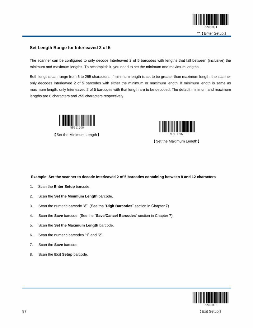
**【Enter Setup】
97 【Exit Setup】
Set Length Range for Interleaved 2 of 5
The scanner can be configured to only decode Interleaved 2 of 5 barcodes with lengths that fall between (inclusive) the
minimum and maximum lengths. To accomplish it, you need to set the minimum and maximum lengths.
Both lengths can range from 5 to 255 characters. If minimum length is set to be greater than maximum length, the scanner
only decodes Interleaved 2 of 5 barcodes with either the minimum or maximum length. If minimum length is same as
maximum length, only Interleaved 2 of 5 barcodes with that length are to be decoded. The default minimum and maximum
lengths are 6 characters and 255 characters respectively.
【Set the Minimum Length】
【Set the Maximum Length】
Example: Set the scanner to decode Interleaved 2 of 5 barcodes containing between 8 and 12 characters
1. Scan the Enter Setup barcode.
2. Scan the Set the Minimum Length barcode.
3. Scan the numeric barcode “8”. (See the “Digit Barcodes” section in Chapter 7)
4. Scan the Save barcode. (See the “Save/Cancel Barcodes” section in Chapter 7)
5. Scan the Set the Maximum Length barcode.
6. Scan the numeric barcodes “1” and “2”.
7. Scan the Save barcode.
8. Scan the Exit Setup barcode.
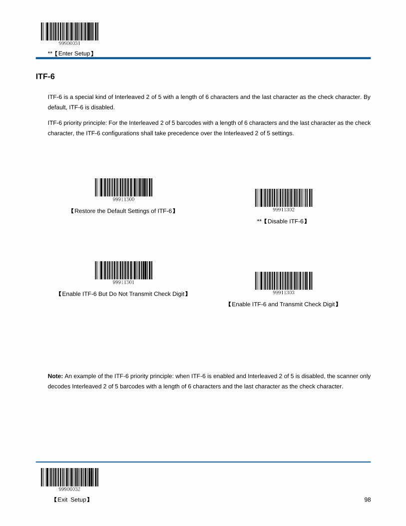
**【Enter Setup】
【Exit Setup】 98
ITF-6
ITF-6 is a special kind of Interleaved 2 of 5 with a length of 6 characters and the last character as the check character. By
default, ITF-6 is disabled.
ITF-6 priority principle: For the Interleaved 2 of 5 barcodes with a length of 6 characters and the last character as the check
character, the ITF-6 configurations shall take precedence over the Interleaved 2 of 5 settings.
【Restore the Default Settings of ITF-6】
**【Disable ITF-6】
【Enable ITF-6 But Do Not Transmit Check Digit】
【Enable ITF-6 and Transmit Check Digit】
Note: An example of the ITF-6 priority principle: when ITF-6 is enabled and Interleaved 2 of 5 is disabled, the scanner only
decodes Interleaved 2 of 5 barcodes with a length of 6 characters and the last character as the check character.

**【Enter Setup】
99 【Exit Setup】
Set Code ID
Code ID can only consist of one or two English letters. See the “Code ID Table” section in Chapter 7 to find the default
Code ID for ITF-6.
To set the Code ID, scan the Set Code ID for ITF-6 barcode, the numeric barcodes corresponding to the hexadecimal
value of a desired ID and the Save barcode.
【Set Code ID for ITF-6】
Example: Set the Code ID of ITF-6 to “p” (its hexadecimal value is 0x70)
1. Scan the Enter Setup barcode.
2. Scan the Set Code ID for ITF-6 barcode.
3. Scan the numeric barcodes “7” and “0”. (See the “Digit Barcodes” section in Chapter 7)
4. Scan the Save barcode. (See the “Save/Cancel Barcodes” section in Chapter 7)
5. Scan the Exit Setup barcode.
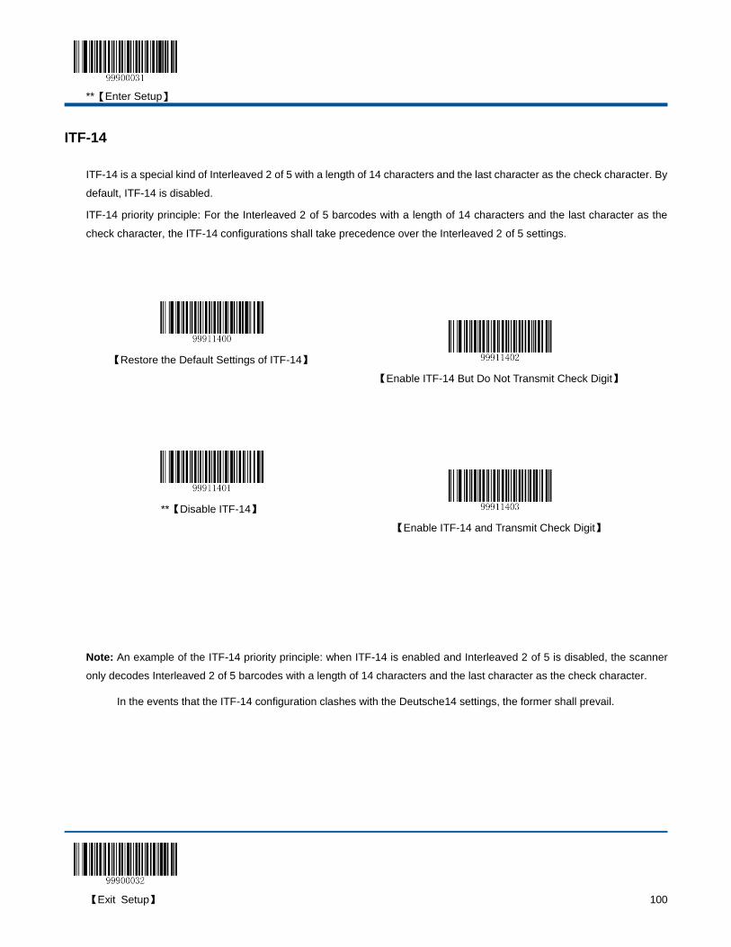
**【Enter Setup】
【Exit Setup】 100
ITF-14
ITF-14 is a special kind of Interleaved 2 of 5 with a length of 14 characters and the last character as the check character. By
default, ITF-14 is disabled.
ITF-14 priority principle: For the Interleaved 2 of 5 barcodes with a length of 14 characters and the last character as the
check character, the ITF-14 configurations shall take precedence over the Interleaved 2 of 5 settings.
【Restore the Default Settings of ITF-14】
【Enable ITF-14 But Do Not Transmit Check Digit】
**【Disable ITF-14】
【Enable ITF-14 and Transmit Check Digit】
Note: An example of the ITF-14 priority principle: when ITF-14 is enabled and Interleaved 2 of 5 is disabled, the scanner
only decodes Interleaved 2 of 5 barcodes with a length of 14 characters and the last character as the check character.
In the events that the ITF-14 configuration clashes with the Deutsche14 settings, the former shall prevail.
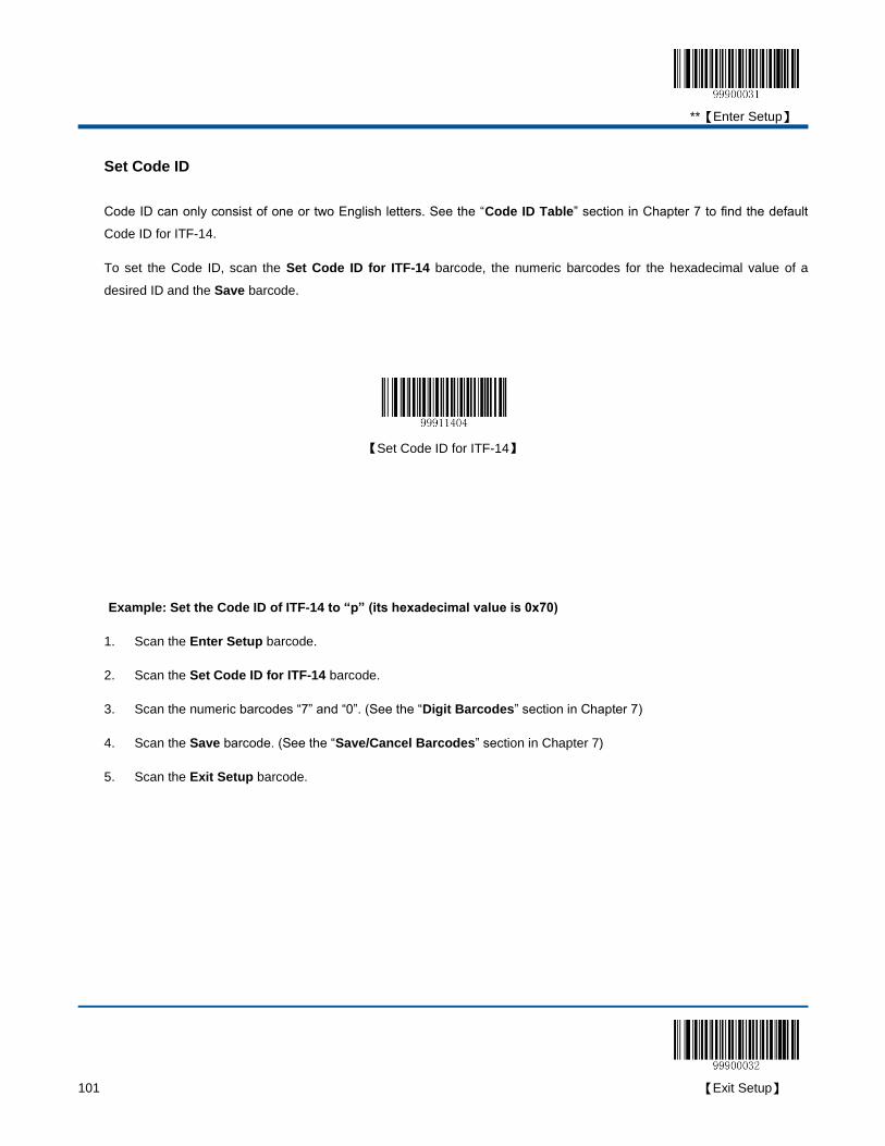
**【Enter Setup】
101 【Exit Setup】
Set Code ID
Code ID can only consist of one or two English letters. See the “Code ID Table” section in Chapter 7 to find the default
Code ID for ITF-14.
To set the Code ID, scan the Set Code ID for ITF-14 barcode, the numeric barcodes for the hexadecimal value of a
desired ID and the Save barcode.
【Set Code ID for ITF-14】
Example: Set the Code ID of ITF-14 to “p” (its hexadecimal value is 0x70)
1. Scan the Enter Setup barcode.
2. Scan the Set Code ID for ITF-14 barcode.
3. Scan the numeric barcodes “7” and “0”. (See the “Digit Barcodes” section in Chapter 7)
4. Scan the Save barcode. (See the “Save/Cancel Barcodes” section in Chapter 7)
5. Scan the Exit Setup barcode.
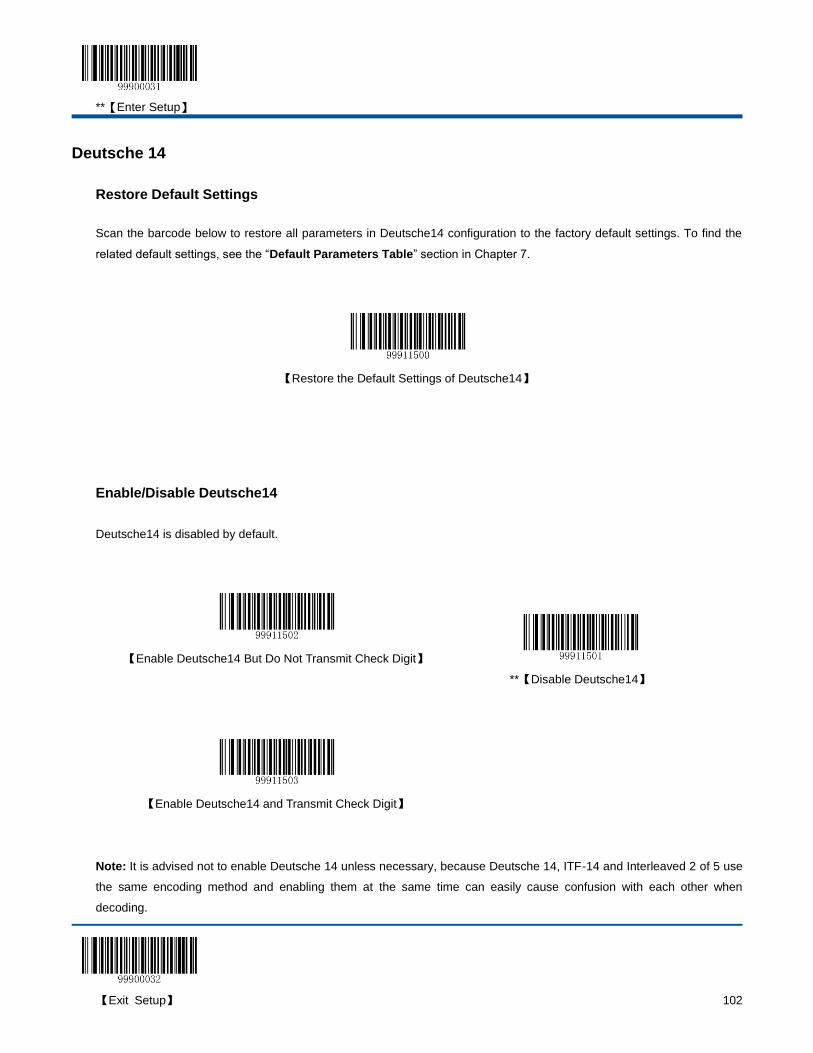
**【Enter Setup】
【Exit Setup】 102
Deutsche 14
Restore Default Settings
Scan the barcode below to restore all parameters in Deutsche14 configuration to the factory default settings. To find the
related default settings, see the “Default Parameters Table” section in Chapter 7.
【Restore the Default Settings of Deutsche14】
Enable/Disable Deutsche14
Deutsche14 is disabled by default.
【Enable Deutsche14 But Do Not Transmit Check Digit】
**【Disable Deutsche14】
【Enable Deutsche14 and Transmit Check Digit】
Note: It is advised not to enable Deutsche 14 unless necessary, because Deutsche 14, ITF-14 and Interleaved 2 of 5 use
the same encoding method and enabling them at the same time can easily cause confusion with each other when
decoding.

**【Enter Setup】
103 【Exit Setup】
Set Code ID
Code ID can only consist of one or two English letters. See the “Code ID Table” section in Chapter 7 to find the default
Code ID for Deutsche14.
To set the Code ID, scan the Set Code ID for Deutsche14 barcode, the numeric barcodes corresponding to the
hexadecimal value of a desired ID and the Save barcode.
【Set Code ID for Deutsche14】
Example: Set the Code ID of Deutsche14 to “p” (its hexadecimal value is 0x70)
1. Scan the Enter Setup barcode.
2. Scan the Set Code ID for Deutsche14 barcode.
3. Scan the numeric barcodes “7” and “0”. (See the “Digit Barcodes” section in Chapter 7)
4. Scan the Save barcode. (See the “Save/Cancel Barcodes” section in Chapter 7)
5. Scan the Exit Setup barcode.

**【Enter Setup】
【Exit Setup】 104
Deutsche 12
Restore Default Settings
Scan the barcode below to restore all parameters in Deutsche12 configuration to the factory default settings. To find the
related default settings, see the “Default Parameters Table” section in Chapter 7.
【Restore the Default Settings of Deutsche12】
Enable/Disable Deutsche 12
Deutsche12 is disabled by default.
【Enable Deutsche12 But Do Not Transmit Check Digit】
**【Disable Deutsche12】
【Enable Deutsche12 and Transmit Check Digit】
Note: It is advised not to enable Deutsche 12 unless necessary, because Deutsche 12, ITF-12 and Interleaved 2 of 5 use
the same encoding method and enabling them at the same time can easily cause confusion with each other when
decoding.

**【Enter Setup】
105 【Exit Setup】
Set Code ID
Code ID can only consist of one or two English letters. See the “Code ID Table” section in Chapter 7 to find the default
Code ID for Deutsche12.
To set the Code ID, scan the Set Code ID for Deutsche 12 barcode, the numeric barcodes corresponding to the
hexadecimal value of a desired ID and the Save barcode.
【Set Code ID for Deutsche12】
Example: Set the Code ID of Deutsche12 to “p” (its hexadecimal value is 0x70)
1. Scan the Enter Setup barcode.
2. Scan the Set Code ID for Deutsche12 barcode.
3. Scan the numeric barcodes “7” and “0”. (See the “Digit Barcodes” section in Chapter 7)
4. Scan the Save barcode. (See the “Save/Cancel Barcodes” section in Chapter 7)
5. Scan the Exit Setup barcode.
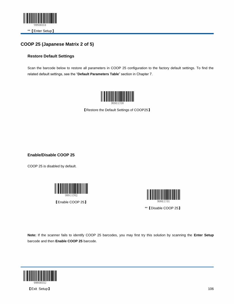
**【Enter Setup】
【Exit Setup】 106
COOP 25 (Japanese Matrix 2 of 5)
Restore Default Settings
Scan the barcode below to restore all parameters in COOP 25 configuration to the factory default settings. To find the
related default settings, see the “Default Parameters Table” section in Chapter 7.
【Restore the Default Settings of COOP25】
Enable/Disable COOP 25
COOP 25 is disabled by default.
【Enable COOP 25】
**【Disable COOP 25】
Note: If the scanner fails to identify COOP 25 barcodes, you may first try this solution by scanning the Enter Setup
barcode and then Enable COOP 25 barcode.
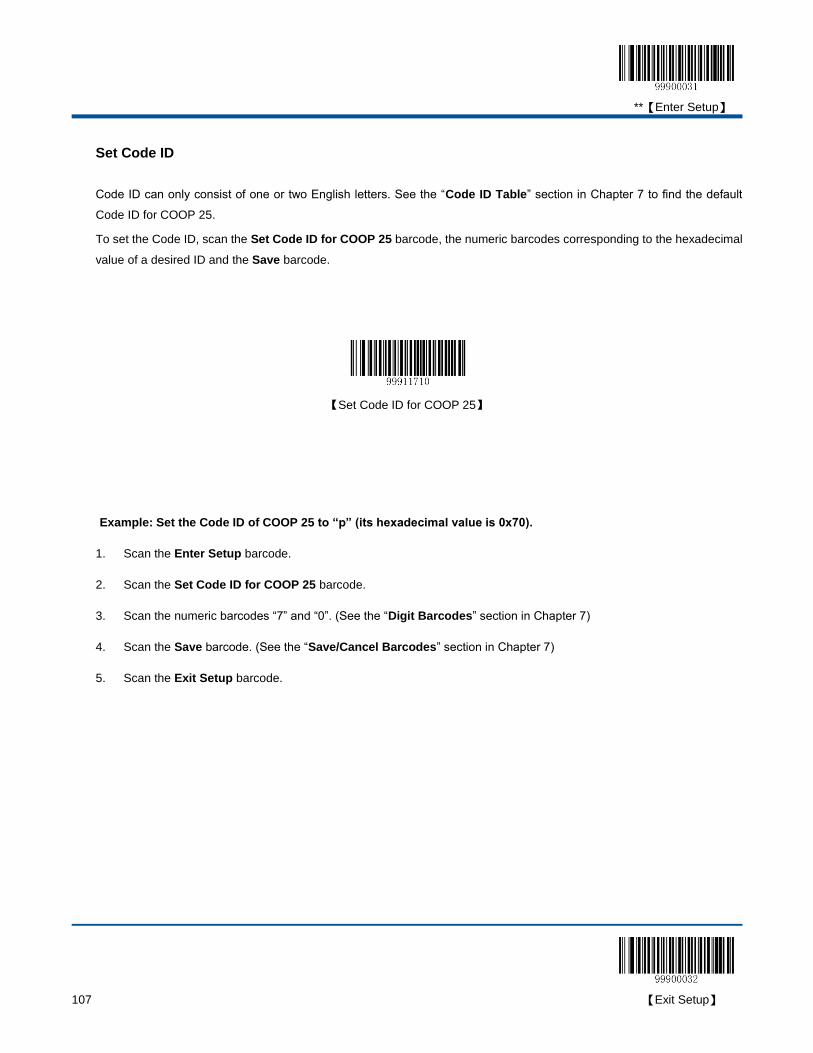
**【Enter Setup】
107 【Exit Setup】
Set Code ID
Code ID can only consist of one or two English letters. See the “Code ID Table” section in Chapter 7 to find the default
Code ID for COOP 25.
To set the Code ID, scan the Set Code ID for COOP 25 barcode, the numeric barcodes corresponding to the hexadecimal
value of a desired ID and the Save barcode.
【Set Code ID for COOP 25】
Example: Set the Code ID of COOP 25 to “p” (its hexadecimal value is 0x70).
1. Scan the Enter Setup barcode.
2. Scan the Set Code ID for COOP 25 barcode.
3. Scan the numeric barcodes “7” and “0”. (See the “Digit Barcodes” section in Chapter 7)
4. Scan the Save barcode. (See the “Save/Cancel Barcodes” section in Chapter 7)
5. Scan the Exit Setup barcode.
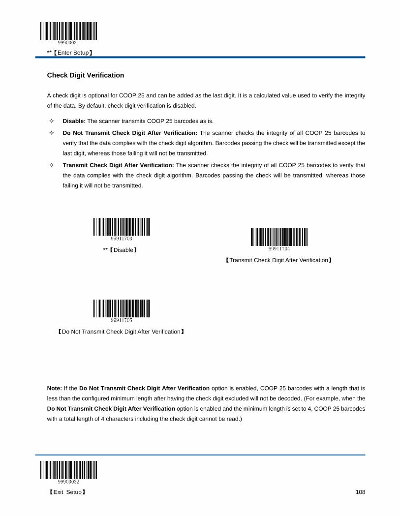
**【Enter Setup】
【Exit Setup】 108
Check Digit Verification
A check digit is optional for COOP 25 and can be added as the last digit. It is a calculated value used to verify the integrity
of the data. By default, check digit verification is disabled.
Disable: The scanner transmits COOP 25 barcodes as is.
Do Not Transmit Check Digit After Verification: The scanner checks the integrity of all COOP 25 barcodes to
verify that the data complies with the check digit algorithm. Barcodes passing the check will be transmitted except the
last digit, whereas those failing it will not be transmitted.
Transmit Check Digit After Verification: The scanner checks the integrity of all COOP 25 barcodes to verify that
the data complies with the check digit algorithm. Barcodes passing the check will be transmitted, whereas those
failing it will not be transmitted.
**【Disable】
【Transmit Check Digit After Verification】
【Do Not Transmit Check Digit After Verification】
Note: If the Do Not Transmit Check Digit After Verification option is enabled, COOP 25 barcodes with a length that is
less than the configured minimum length after having the check digit excluded will not be decoded. (For example, when the
Do Not Transmit Check Digit After Verification option is enabled and the minimum length is set to 4, COOP 25 barcodes
with a total length of 4 characters including the check digit cannot be read.)

**【Enter Setup】
109 【Exit Setup】
Set Length Range for COOP 25
The scanner can be configured to only decode COOP 25 barcodes with lengths that fall between (inclusive) the minimum
and maximum lengths. To accomplish it, you need to set the minimum and maximum lengths.
Both lengths can range from 3 to 255 characters. If minimum length is set to be greater than maximum length, the scanner
only decodes COOP 25 barcodes with either the minimum or maximum length. If minimum length is same as maximum
length, only COOP 25 barcodes with that length are to be decoded. The default minimum and maximum lengths are 6
characters and 255 characters respectively.
【Set the Minimum Length】
【Set the Maximum Length】
Example: Set the scanner to decode COOP 25 barcodes containing between 8 and 12 characters
1. Scan the Enter Setup barcode.
2. Scan the Set the Minimum Length barcode.
3. Scan the numeric barcode “8”. (See the “Digit Barcodes” section in Chapter 7)
4. Scan the Save barcode. (See the “Save/Cancel Barcodes” section in Chapter 7)
5. Scan the Set the Maximum Length barcode.
6. Scan the numeric barcodes “1” and “2”.
7. Scan the Save barcode.
8. Scan the Exit Setup barcode.
**【Enter Setup】
【Exit Setup】 110
Matrix 2 of 5 (European Matrix 2 of 5)
Restore Default Settings
Scan the barcode below to restore all parameters in Matrix 2 of 5 configuration to the factory default settings. To find the
related default settings, see the “Default Parameters Table” section in Chapter 7.
【Restore the Default Settings of Matrix 2 of 5】
Enable/Disable Matrix 2 of 5
Matrix 2 of 5 is enabled by default.
**【Enable Matrix 2 of 5】
【Disable Matrix 2 of 5】
Note: If the scanner fails to identify Matrix 2 of 5 barcodes, you may first try this solution by scanning the Enter Setup
barcode and then Enable Matrix 2 of 5 barcode.

**【Enter Setup】
111 【Exit Setup】
Set Code ID
Code ID can only consist of one or two English letters. See the “Code ID Table” section in Chapter 7 to find the default
Code ID for Matrix 2 of 5.
To set the Code ID, scan the Set Code ID for Matrix 2 of 5 barcode, the numeric barcodes corresponding to the
hexadecimal value of a desired ID and the Save barcode.
【Set Code ID for Matrix 2 of 5】
Example: Set the Code ID of Matrix 2 of 5 to “p” (its hexadecimal value is 0x70)
1. Scan the Enter Setup barcode.
2. Scan the Set Code ID for Matrix 2 of 5 barcode.
3. Scan the numeric barcodes “7” and “0”. (See the “Digit Barcodes” section in Chapter 7)
4. Scan the Save barcode. (See the “Save/Cancel Barcodes” section in Chapter 7)
5. Scan the Exit Setup barcode.
**【Enter Setup】
【Exit Setup】 112
Check Digit Verification
A check digit is optional for Matrix 2 of 5 and can be added as the last digit. It is a calculated value used to verify the
integrity of the data. By default, check digit verification is disabled.
Disable: The scanner transmits Matrix 2 of 5 barcodes as is.
Do Not Transmit Check Digit After Verification: The scanner checks the integrity of all Matrix 2 of 5 barcodes to
verify that the data complies with the check digit algorithm. Barcodes passing the check will be transmitted except the
last digit, whereas those failing it will not be transmitted.
Transmit Check Digit After Verification: The scanner checks the integrity of all Matrix 2 of 5 barcodes to verify that
the data complies with the check digit algorithm. Barcodes passing the check will be transmitted, whereas those
failing it will not be transmitted.
**【Disable】
【Transmit Check Digit After Verification】
【Do Not Transmit Check Digit After Verification】
Note: If the Do Not Transmit Check Digit After Verification option is enabled, Matrix 2 of 5 barcodes with a length that is
less than the configured minimum length after having the check digit excluded will not be decoded. (For example, when the
Do Not Transmit Check Digit After Verification option is enabled and the minimum length is set to 4, Matrix 2 of 5
barcodes with a total length of 4 characters including the check digit cannot be read.)

**【Enter Setup】
113 【Exit Setup】
Set Length Range for Matrix 2 of 5
The scanner can be configured to only decode Matrix 2 of 5 barcodes with lengths that fall between (inclusive) the
minimum and maximum lengths. To accomplish it, you need to set the minimum and maximum lengths.
Both lengths can range from 3 to 255 characters. If minimum length is set to be greater than maximum length, the scanner
only decodes Matrix 2 of 5 barcodes with either the minimum or maximum length. If minimum length is same as maximum
length, only Matrix 2 of 5 barcodes with that length are to be decoded. The default minimum and maximum lengths are 6
characters and 255 characters respectively.
【Set the Minimum Length】
【Set the Maximum Length】
Example: Set the scanner to decode Matrix 2 of 5 barcodes containing between 8 and 12 characters
1. Scan the Enter Setup barcode.
2. Scan the Set the Minimum Length barcode.
3. Scan the numeric barcode “8”. (See the “Digit Barcodes” section in Chapter 7)
4. Scan the Save barcode. (See the “Save/Cancel Barcodes” section in Chapter 7)
5. Scan the Set the Maximum Length barcode.
6. Scan the numeric barcodes “1” and “2”.
7. Scan the Save barcode.
8. Scan the Exit Setup barcode.

**【Enter Setup】
【Exit Setup】 114
Industrial 25
Restore Default Settings
Scan the barcode below to restore all parameters in Industrial 25 configuration to the factory default settings. To find the
related default settings, see the “Default Parameters Table” section in Chapter 7.
【Restore the Default Settings of Industrial 25】
Enable/Disable Industrial 25
Industrial 25 is enabled by default.
**【Enable Industrial 25】
【Disable Industrial 25】
Note: If the scanner fails to identify Industrial 25 barcodes, you may first try this solution by scanning the Enter Setup
barcode and then Enable Industrial 25 barcode.

**【Enter Setup】
115 【Exit Setup】
Set Code ID
Code ID can only consist of one or two English letters. See the “Code ID Table” section in Chapter 7 to find the default
Code ID for Industrial 25.
To set the Code ID, scan the Set Code ID for Industrial 25 barcode, the numeric barcodes corresponding to the
hexadecimal value of a desired ID and the Save barcode.
【Set Code ID for Industrial 25】
Example: Set the Code ID of Industrial 25 to “p” (its hexadecimal value is 0x70)
1. Scan the Enter Setup barcode.
2. Scan the Set Code ID for Industrial 25 barcode.
3. Scan the numeric barcodes “7” and “0”. (See the “Digit Barcodes” section in Chapter 7)
4. Scan the Save barcode. (See the “Save/Cancel Barcodes” section in Chapter 7)
5. Scan the Exit Setup barcode.

**【Enter Setup】
【Exit Setup】 116
Check Digit Verification
A check digit is optional for Industrial 25 and can be added as the last digit. It is a calculated value used to verify the
integrity of the data. By default, the scanner transmits check digit after verification.
Disable: The scanner transmits Industrial 25 barcodes as is.
Do Not Transmit Check Digit After Verification: The scanner checks the integrity of all Industrial 25 barcodes to
verify that the data complies with the check digit algorithm. Barcodes passing the check will be transmitted except the
last digit, whereas those failing it will not be transmitted.
Transmit Check Digit After Verification: The scanner checks the integrity of all Industrial 25 barcodes to verify that
the data complies with the check digit algorithm. Barcodes passing the check will be transmitted, whereas those
failing it will not be transmitted.
【Disable】
**【Transmit Check Digit After Verification】
【Do Not Transmit Check Digit After Verification】
Note: If the Do Not Transmit Check Digit After Verification option is enabled, Industrial 25 barcodes with a length that is
less than the configured minimum length after having the check digit excluded will not be decoded. (For example, when the
Do Not Transmit Check Digit After Verification option is enabled and the minimum length is set to 4, Industrial 25
barcodes with a total length of 4 characters including the check digit cannot be read.)

**【Enter Setup】
117 【Exit Setup】
Set Length Range for Industrial 25
The scanner can be configured to only decode Industrial 25 barcodes with lengths that fall between (inclusive) the
minimum and maximum lengths. To accomplish it, you need to set the minimum and maximum lengths.
Both lengths can range from 4 to 255 characters. If minimum length is set to be greater than maximum length, the scanner
only decodes Industrial 25 barcodes with either the minimum or maximum length. If minimum length is same as maximum
length, only Industrial 25 barcodes with that length are to be decoded. The default minimum and maximum lengths are 6
characters and 255 characters respectively.
【Set the Minimum Length】
【Set the Maximum Length】
Example: Set the scanner to decode Industrial 25 barcodes containing between 8 and 12 characters
1. Scan the Enter Setup barcode.
2. Scan the Set the Minimum Length barcode.
3. Scan the numeric barcode “8”. (See the “Digit Barcodes” section in Chapter 7)
4. Scan the Save barcode. (See the “Save/Cancel Barcodes” section in Chapter 7)
5. Scan the Set the Maximum Length barcode.
6. Scan the numeric barcodes “1” and “2”.
7. Scan the Save barcode.
8. Scan the Exit Setup barcode.

**【Enter Setup】
【Exit Setup】 118
Standard 25
Restore Default Settings
Scan the barcode below to restore all parameters in Standard 25 configuration to the factory default settings. To find the
related default settings, see the “Default Parameters Table” section in Chapter 7.
【Restore the Default Settings of Standard 25】
Enable/Disable Standard 25
Standard 25 is enabled by default.
**【Enable Standard 25】
【Disable Standard 25】
Note: If the scanner fails to identify Standard 25 barcodes, you may first try this solution by scanning the Enter Setup
barcode and then Enable Standard 25 barcode.
**【Enter Setup】
119 【Exit Setup】
Set Code ID
Code ID can only consist of one or two English letters. See the “Code ID Table” section in Chapter 7 to find the default
Code ID for Standard 25.
To set the Code ID, scan the Set Code ID for Standard 25 barcode, the numeric barcodes corresponding to the
hexadecimal value of a desired ID and the Save barcode.
【Set Code ID for Standard 25】
Example: Set the Code ID of Standard 25 to “p” (its hexadecimal value is 0x70)
1. Scan the Enter Setup barcode.
2. Scan the Set Code ID for Standard 25 barcode.
3. Scan the numeric barcodes “7” and “0”. (See the “Digit Barcodes” section in Chapter 7)
4. Scan the Save barcode. (See the “Save/Cancel Barcodes” section in Chapter 7)
5. Scan the Exit Setup barcode.
**【Enter Setup】
【Exit Setup】 120
Check Digit Verification
A check digit is optional for Standard 25 and can be added as the last digit. It is a calculated value used to verify the
integrity of the data. By default, check digit verification is disabled.
Disable: The scanner transmits Standard 25 barcodes as is.
Do Not Transmit Check Digit After Verification: The scanner checks the integrity of all Standard 25 barcodes to
verify that the data complies with the check digit algorithm. Barcodes passing the check will be transmitted except the
last digit, whereas those failing it will not be transmitted.
Transmit Check Digit After Verification: The scanner checks the integrity of all Standard 25 barcodes to verify that
the data complies with the check digit algorithm. Barcodes passing the check will be transmitted, whereas those
failing it will not be transmitted.
**【Disable】
【Transmit Check Digit After Verification】
【Do Not Transmit Check Digit After Verification】
Note: If the Do Not Transmit Check Digit After Verification option is enabled, Standard 25 barcodes with a length that is
less than the configured minimum length after having the check digit excluded will not be decoded. (For example, when the
Do Not Transmit Check Digit After Verification option is enabled and the minimum length is set to 4, Standard 25
barcodes with a total length of 4 characters including the check digit cannot be read.)

**【Enter Setup】
121 【Exit Setup】
Set Length Range for Standard 25
The scanner can be configured to only decode Standard 25 barcodes with lengths that fall between (inclusive) the
minimum and maximum lengths. To accomplish it, you need to set the minimum and maximum lengths.
Both lengths can range from 4 to 255 characters. If minimum length is set to be greater than maximum length, the scanner
only decodes Standard 25 barcodes with either the minimum or maximum length. If minimum length is same as maximum
length, only Standard 25 barcodes with that length are to be decoded. The default minimum and maximum lengths are 6
characters and 255 characters respectively.
【Set the Minimum Length】
【Set the Maximum Length】
Example: Set the scanner to decode Standard 25 barcodes containing between 8 and 12 characters
1. Scan the Enter Setup barcode.
2. Scan the Set the Minimum Length barcode.
3. Scan the numeric barcode “8”. (See the “Digit Barcodes” section in Chapter 7)
4. Scan the Save barcode. (See the “Save/Cancel Barcodes” section in Chapter 7)
5. Scan the Set the Maximum Length barcode.
6. Scan the numeric barcodes “1” and “2”.
7. Scan the Save barcode.
8. Scan the Exit Setup barcode.
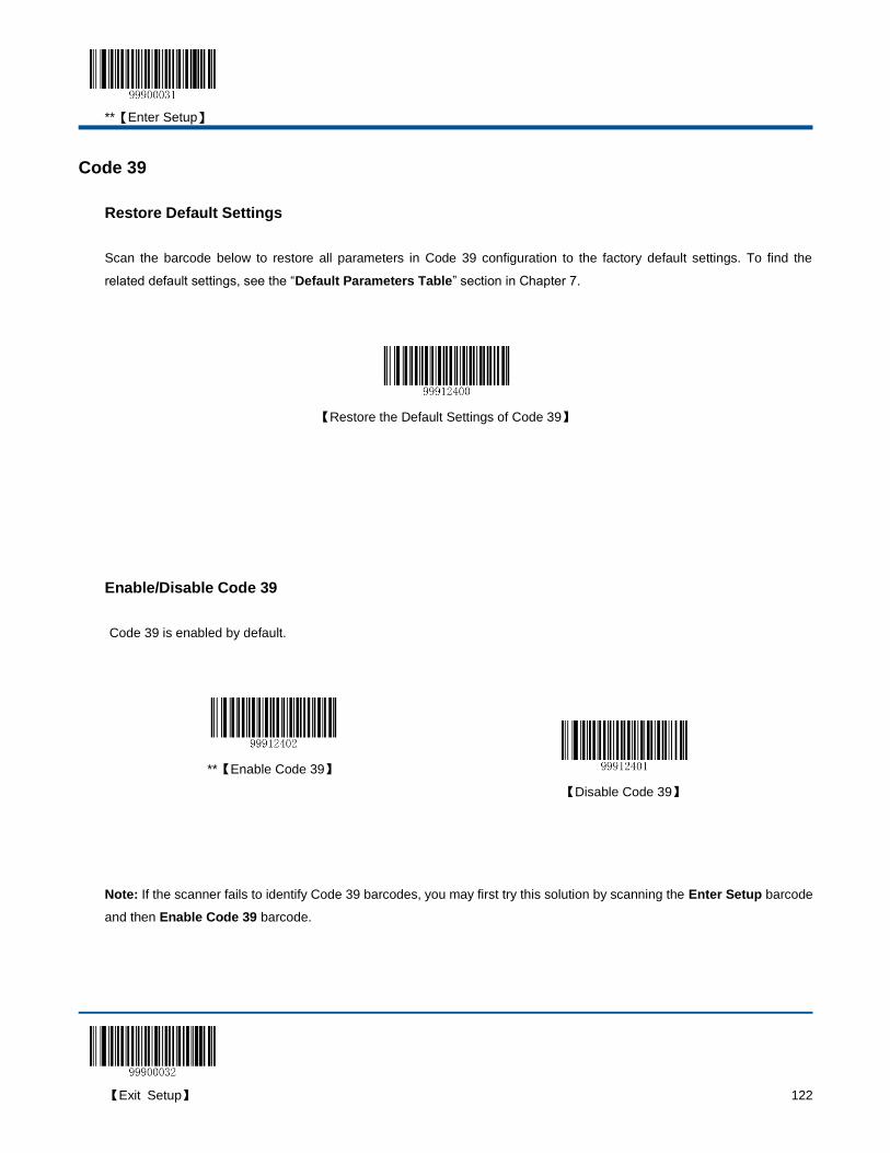
**【Enter Setup】
【Exit Setup】 122
Code 39
Restore Default Settings
Scan the barcode below to restore all parameters in Code 39 configuration to the factory default settings. To find the
related default settings, see the “Default Parameters Table” section in Chapter 7.
【Restore the Default Settings of Code 39】
Enable/Disable Code 39
Code 39 is enabled by default.
**【Enable Code 39】
【Disable Code 39】
Note: If the scanner fails to identify Code 39 barcodes, you may first try this solution by scanning the Enter Setup barcode
and then Enable Code 39 barcode.

**【Enter Setup】
123 【Exit Setup】
Set Code ID
Code ID can only consist of one or two English letters. See the “Code ID Table” section in Chapter 7 to find the default
Code ID for Code 39.
To set the Code ID, scan the Set Code ID for Code 39 barcode, the numeric barcodes corresponding to the hexadecimal
value of a desired ID and the Save barcode.
【Set Code ID for Code 39】
Example: Set the Code ID of Code 39 to “p” (its hexadecimal value is 0x70)
1. Scan the Enter Setup barcode.
2. Scan the Set Code ID for Code 39 barcode.
3. Scan the numeric barcodes “7” and “0”. (See the “Digit Barcodes” section in Chapter 7)
4. Scan the Save barcode. (See the “Save/Cancel Barcodes” section in Chapter 7)
5. Scan the Exit Setup barcode.
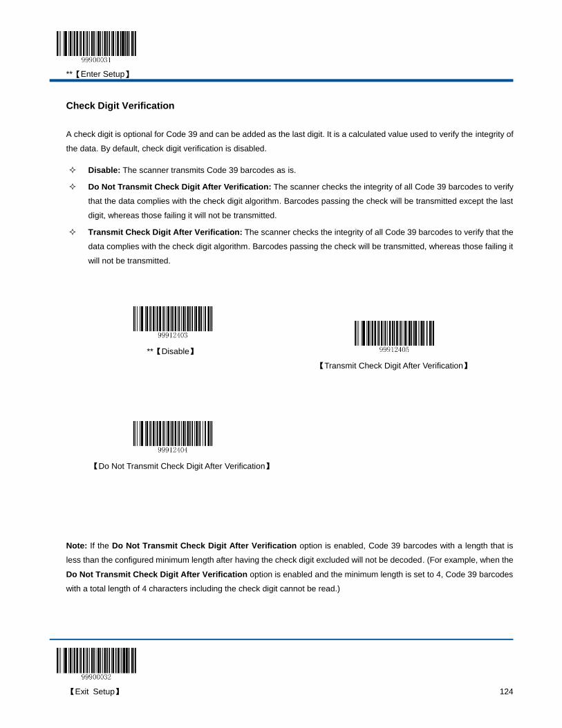
**【Enter Setup】
【Exit Setup】 124
Check Digit Verification
A check digit is optional for Code 39 and can be added as the last digit. It is a calculated value used to verify the integrity of
the data. By default, check digit verification is disabled.
Disable: The scanner transmits Code 39 barcodes as is.
Do Not Transmit Check Digit After Verification: The scanner checks the integrity of all Code 39 barcodes to verify
that the data complies with the check digit algorithm. Barcodes passing the check will be transmitted except the last
digit, whereas those failing it will not be transmitted.
Transmit Check Digit After Verification: The scanner checks the integrity of all Code 39 barcodes to verify that the
data complies with the check digit algorithm. Barcodes passing the check will be transmitted, whereas those failing it
will not be transmitted.
**【Disable】
【Transmit Check Digit After Verification】
【Do Not Transmit Check Digit After Verification】
Note: If the Do Not Transmit Check Digit After Verification option is enabled, Code 39 barcodes with a length that is
less than the configured minimum length after having the check digit excluded will not be decoded. (For example, when the
Do Not Transmit Check Digit After Verification option is enabled and the minimum length is set to 4, Code 39 barcodes
with a total length of 4 characters including the check digit cannot be read.)
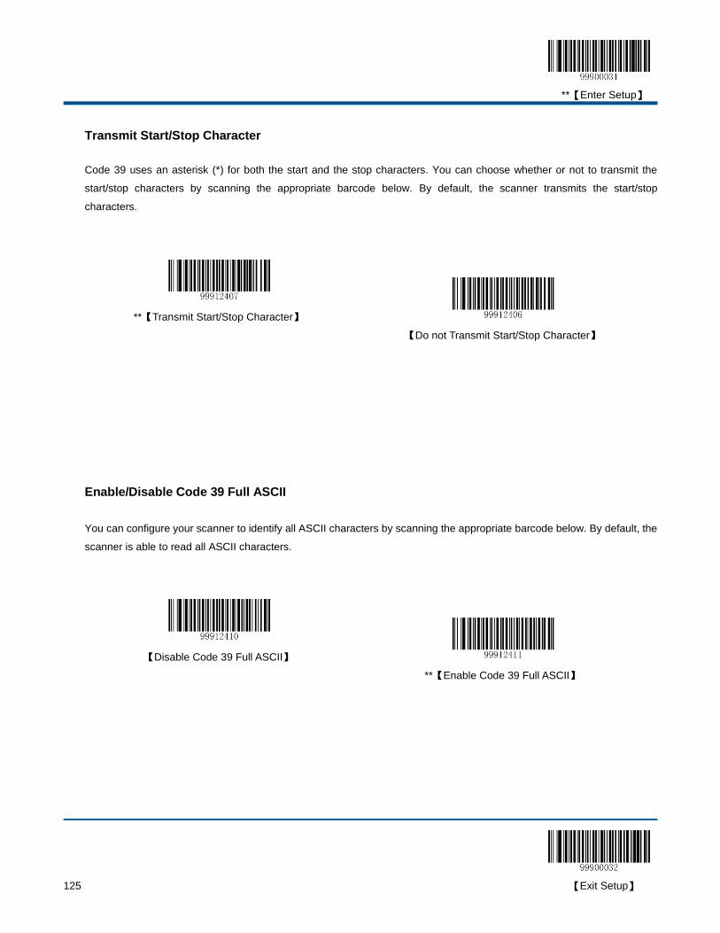
**【Enter Setup】
125 【Exit Setup】
Transmit Start/Stop Character
Code 39 uses an asterisk (*) for both the start and the stop characters. You can choose whether or not to transmit the
start/stop characters by scanning the appropriate barcode below. By default, the scanner transmits the start/stop
characters.
**【Transmit Start/Stop Character】
【Do not Transmit Start/Stop Character】
Enable/Disable Code 39 Full ASCII
You can configure your scanner to identify all ASCII characters by scanning the appropriate barcode below. By default, the
scanner is able to read all ASCII characters.
【Disable Code 39 Full ASCII】
**【Enable Code 39 Full ASCII】
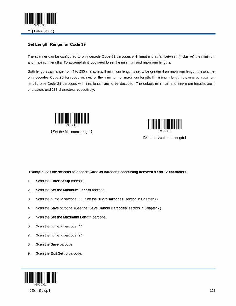
**【Enter Setup】
【Exit Setup】 126
Set Length Range for Code 39
The scanner can be configured to only decode Code 39 barcodes with lengths that fall between (inclusive) the minimum
and maximum lengths. To accomplish it, you need to set the minimum and maximum lengths.
Both lengths can range from 4 to 255 characters. If minimum length is set to be greater than maximum length, the scanner
only decodes Code 39 barcodes with either the minimum or maximum length. If minimum length is same as maximum
length, only Code 39 barcodes with that length are to be decoded. The default minimum and maximum lengths are 4
characters and 255 characters respectively.
【Set the Minimum Length】
【Set the Maximum Length】
Example: Set the scanner to decode Code 39 barcodes containing between 8 and 12 characters.
1. Scan the Enter Setup barcode.
2. Scan the Set the Minimum Length barcode.
3. Scan the numeric barcode “8”. (See the “Digit Barcodes” section in Chapter 7)
4. Scan the Save barcode. (See the “Save/Cancel Barcodes” section in Chapter 7)
5. Scan the Set the Maximum Length barcode.
6. Scan the numeric barcode “1”.
7. Scan the numeric barcode “2”.
8. Scan the Save barcode.
9. Scan the Exit Setup barcode.
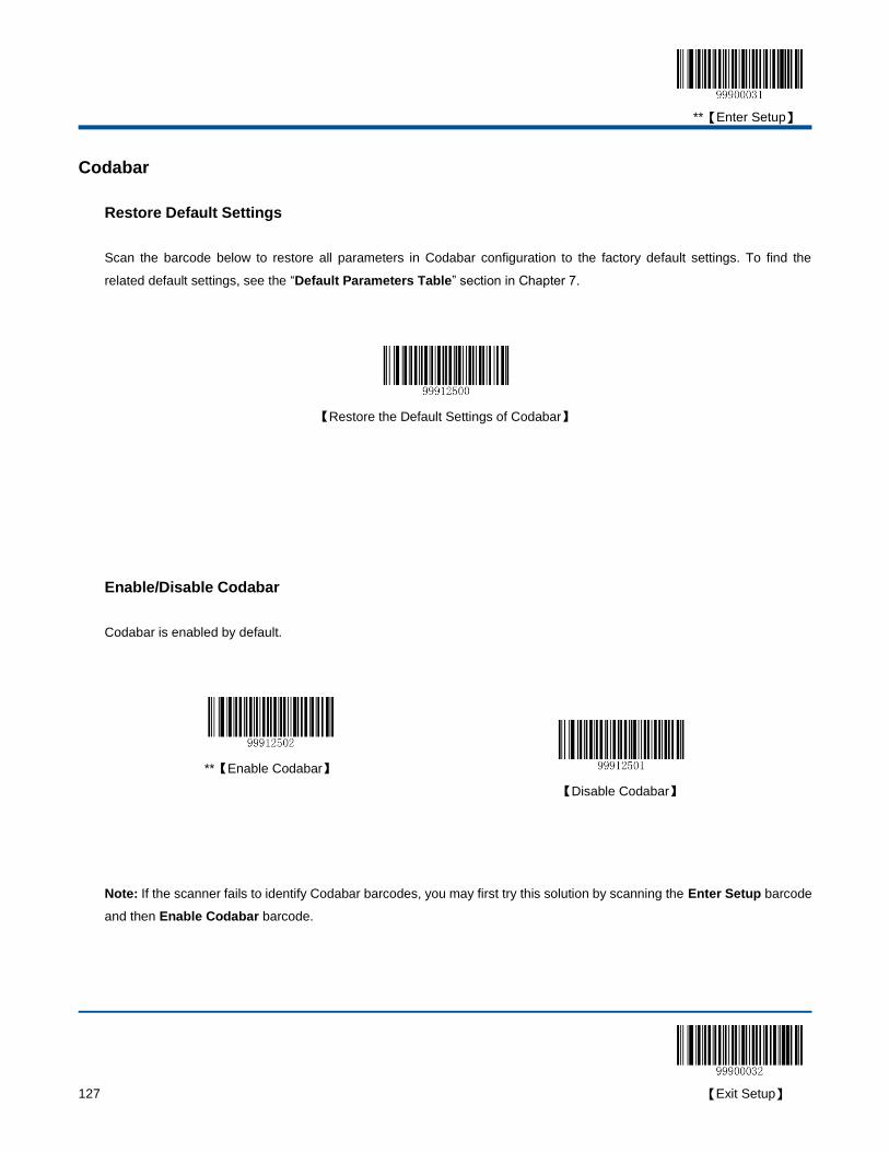
**【Enter Setup】
127 【Exit Setup】
Codabar
Restore Default Settings
Scan the barcode below to restore all parameters in Codabar configuration to the factory default settings. To find the
related default settings, see the “Default Parameters Table” section in Chapter 7.
【Restore the Default Settings of Codabar】
Enable/Disable Codabar
Codabar is enabled by default.
**【Enable Codabar】
【Disable Codabar】
Note: If the scanner fails to identify Codabar barcodes, you may first try this solution by scanning the Enter Setup barcode
and then Enable Codabar barcode.
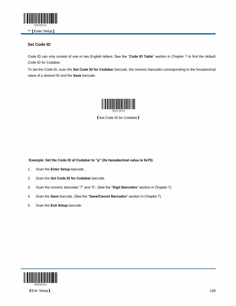
**【Enter Setup】
【Exit Setup】 128
Set Code ID
Code ID can only consist of one or two English letters. See the “Code ID Table” section in Chapter 7 to find the default
Code ID for Codabar.
To set the Code ID, scan the Set Code ID for Codabar barcode, the numeric barcodes corresponding to the hexadecimal
value of a desired ID and the Save barcode.
【Set Code ID for Codabar】
Example: Set the Code ID of Codabar to “p” (its hexadecimal value is 0x70)
1. Scan the Enter Setup barcode.
2. Scan the Set Code ID for Codabar barcode.
3. Scan the numeric barcodes “7” and “0”. (See the “Digit Barcodes” section in Chapter 7)
4. Scan the Save barcode. (See the “Save/Cancel Barcodes” section in Chapter 7)
5. Scan the Exit Setup barcode.
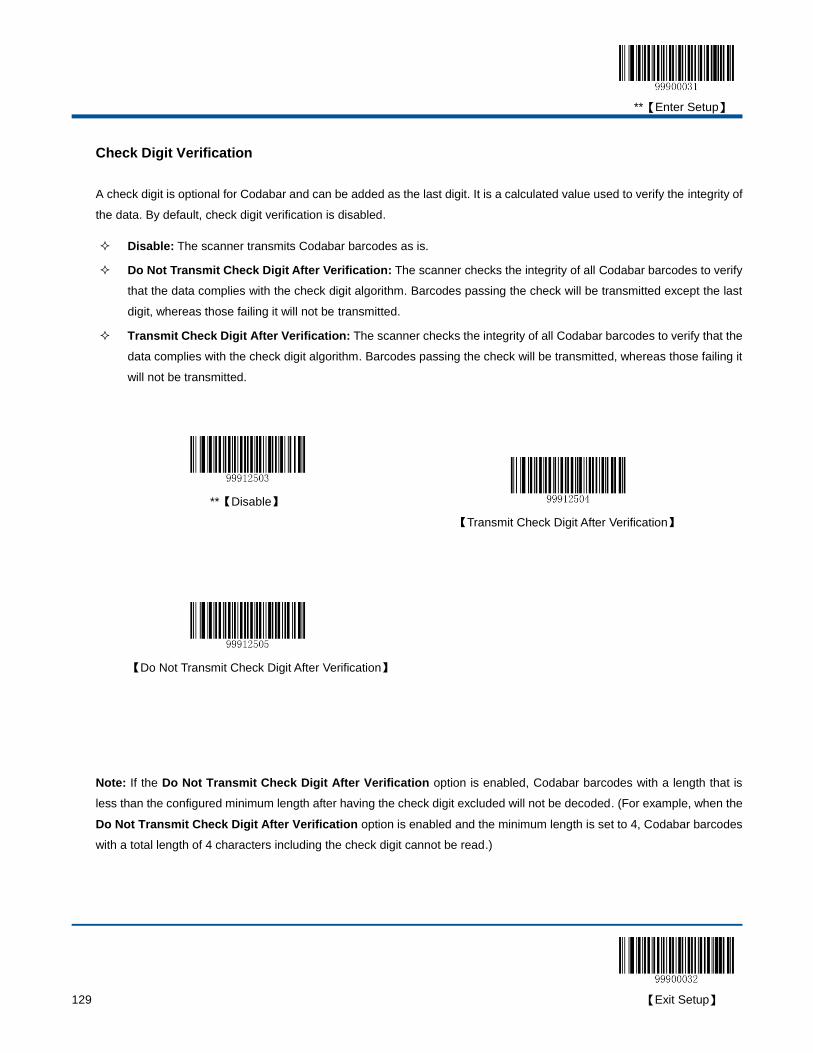
**【Enter Setup】
129 【Exit Setup】
Check Digit Verification
A check digit is optional for Codabar and can be added as the last digit. It is a calculated value used to verify the integrity of
the data. By default, check digit verification is disabled.
Disable: The scanner transmits Codabar barcodes as is.
Do Not Transmit Check Digit After Verification: The scanner checks the integrity of all Codabar barcodes to verify
that the data complies with the check digit algorithm. Barcodes passing the check will be transmitted except the last
digit, whereas those failing it will not be transmitted.
Transmit Check Digit After Verification: The scanner checks the integrity of all Codabar barcodes to verify that the
data complies with the check digit algorithm. Barcodes passing the check will be transmitted, whereas those failing it
will not be transmitted.
**【Disable】
【Transmit Check Digit After Verification】
【Do Not Transmit Check Digit After Verification】
Note: If the Do Not Transmit Check Digit After Verification option is enabled, Codabar barcodes with a length that is
less than the configured minimum length after having the check digit excluded will not be decoded. (For example, when the
Do Not Transmit Check Digit After Verification option is enabled and the minimum length is set to 4, Codabar barcodes
with a total length of 4 characters including the check digit cannot be read.)
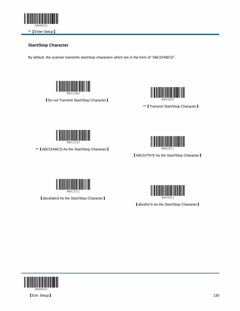
**【Enter Setup】
【Exit Setup】 130
Start/Stop Character
By default, the scanner transmits start/stop characters which are in the form of “ABCD/ABCD”.
【Do not Transmit Start/Stop Character】
**【Transmit Start/Stop Character】
**【ABCD/ABCD As the Start/Stop Character】
【ABCD/TN*E As the Start/Stop Character】
【abcd/abcd As the Start/Stop Character】
【abcd/tn*e As the Start/Stop Character】

**【Enter Setup】
131 【Exit Setup】
Set Length Range for Codabar
The scanner can be configured to only decode Codabar barcodes with lengths that fall between (inclusive) the minimum
and maximum lengths. To accomplish it, you need to set the minimum and maximum lengths.
Both lengths can range from 2 to 255 characters. If minimum length is set to be greater than maximum length, the scanner
only decodes Codabar barcodes with either the minimum or maximum length. If minimum length is same as maximum
length, only Codabar barcodes with that length are to be decoded. The default minimum and maximum lengths are 4
characters and 255 characters respectively.
【Set the Minimum Length】
【Set the Maximum Length】
Example: Set the scanner to decode Codabar barcodes containing between 8 and 12 characters.
1. Scan the Enter Setup barcode.
2. Scan the Set the Minimum Length barcode.
3. Scan the numeric barcode “8”. (See the “Digit Barcodes” section in Chapter 7)
4. Scan the Save barcode. (See the “Save/Cancel Barcodes” section in Chapter 7)
5. Scan the Set the Maximum Length barcode.
6. Scan the numeric barcode “1”.
7. Scan the numeric barcode “2”.
8. Scan the Save barcode.
9. Scan the Exit Setup barcode.

**【Enter Setup】
【Exit Setup】 132
Code 93
Restore Default Settings
Scan the barcode below to restore all parameters in Code 93 configuration to the factory default settings. To find the
related default settings, see the “Default Parameters Table” section in Chapter 7.
【Restore the Default Settings of Code 93】
Enable/Disable Code 93
Code 93 is enabled by default.
**【Enable Code 93】
【Disable Code 93】
Note: If the scanner fails to identify Code 93 barcodes, you may first try this solution by scanning the Enter Setup barcode
and then Enable Code 93 barcode.

**【Enter Setup】
133 【Exit Setup】
Set Code ID
Code ID can only consist of one or two English letters. See the “Code ID Table” section in Chapter 7 to find the default
Code ID for Code 93.
To set the Code ID, scan the Set Code ID for Code 93 barcode, the numeric barcodes corresponding to the hexadecimal
value of a desired ID and the Save barcode.
【Set Code ID for Code 93】
Example: Set the Code ID of Code 93 to “p” (its hexadecimal value is 0x70)
1. Scan the Enter Setup barcode.
2. Scan the Set Code ID for Code 93 barcode.
3. Scan the numeric barcodes “7” and “0”. (See the “Digit Barcodes” section in Chapter 7)
4. Scan the Save barcode. (See the “Save/Cancel Barcodes” section in Chapter 7)
5. Scan the Exit Setup barcode.
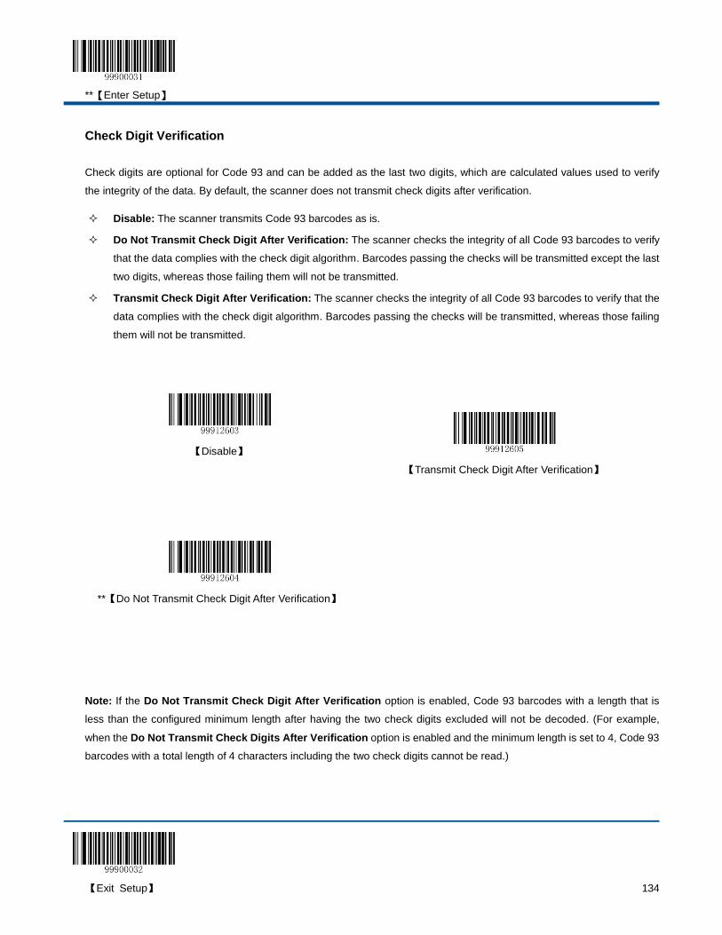
**【Enter Setup】
【Exit Setup】 134
Check Digit Verification
Check digits are optional for Code 93 and can be added as the last two digits, which are calculated values used to verify
the integrity of the data. By default, the scanner does not transmit check digits after verification.
Disable: The scanner transmits Code 93 barcodes as is.
Do Not Transmit Check Digit After Verification: The scanner checks the integrity of all Code 93 barcodes to verify
that the data complies with the check digit algorithm. Barcodes passing the checks will be transmitted except the last
two digits, whereas those failing them will not be transmitted.
Transmit Check Digit After Verification: The scanner checks the integrity of all Code 93 barcodes to verify that the
data complies with the check digit algorithm. Barcodes passing the checks will be transmitted, whereas those failing
them will not be transmitted.
【Disable】
【Transmit Check Digit After Verification】
**【Do Not Transmit Check Digit After Verification】
Note: If the Do Not Transmit Check Digit After Verification option is enabled, Code 93 barcodes with a length that is
less than the configured minimum length after having the two check digits excluded will not be decoded. (For example,
when the Do Not Transmit Check Digits After Verification option is enabled and the minimum length is set to 4, Code 93
barcodes with a total length of 4 characters including the two check digits cannot be read.)

**【Enter Setup】
135 【Exit Setup】
Set Length Range for Code 93
The scanner can be configured to only decode Code 93 barcodes with lengths that fall between (inclusive) the minimum
and maximum lengths. To accomplish it, you need to set the minimum and maximum lengths.
Both lengths can range from 1 to 255 characters. If minimum length is set to be greater than maximum length, the scanner
only decodes Code 93 barcodes with either the minimum or maximum length. If minimum length is same as maximum
length, only Code 93 barcodes with that length are to be decoded. The default minimum and maximum lengths are 2
characters and 255 characters respectively.
【Set the Minimum Length】
【Set the Maximum Length】
Example: Set the scanner to decode Code 93 barcodes containing between 8 and 12 characters.
1. Scan the Enter Setup barcode.
2. Scan the Set the Minimum Length barcode.
3. Scan the numeric barcode “8”. (See the “Digit Barcodes” section in Chapter 7)
4. Scan the Save barcode. (See the “Save/Cancel Barcodes” section in Chapter 7)
5. Scan the Set the Maximum Length barcode.
6. Scan the numeric barcode “1”.
7. Scan the numeric barcode “2”.
8. Scan the Save barcode.
9. Scan the Exit Setup barcode.

**【Enter Setup】
【Exit Setup】 136
Code 11
Restore Default Settings
Scan the barcode below to restore all parameters in Code 11 configuration to the factory default settings. To find the
related default settings, see the “Default Parameters Table” section in Chapter 7.
【Restore the Default Settings of Code 11】
Enable/Disable Code 11
Code 11 is disabled by default.
【Enable Code 11】
**【Disable Code 11】
Note: If the scanner fails to identify Code 11 barcodes, you may first try this solution by scanning the Enter Setup barcode
and then Enable Code 11 barcode.
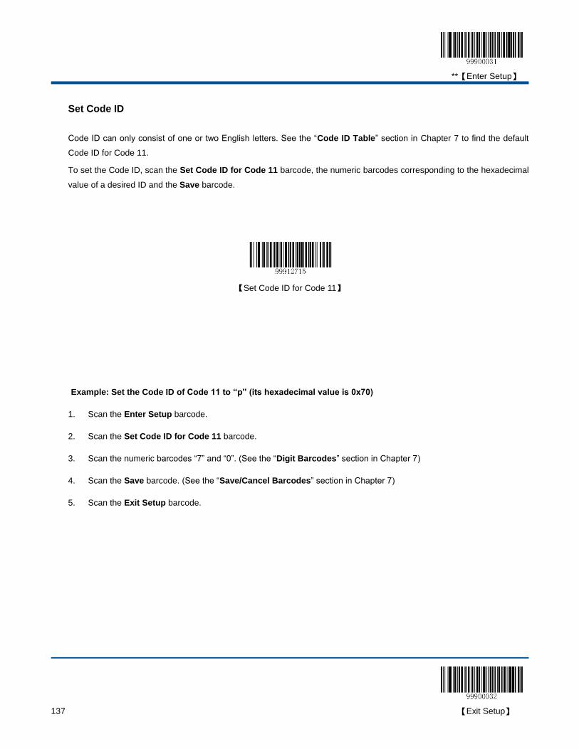
**【Enter Setup】
137 【Exit Setup】
Set Code ID
Code ID can only consist of one or two English letters. See the “Code ID Table” section in Chapter 7 to find the default
Code ID for Code 11.
To set the Code ID, scan the Set Code ID for Code 11 barcode, the numeric barcodes corresponding to the hexadecimal
value of a desired ID and the Save barcode.
【Set Code ID for Code 11】
Example: Set the Code ID of Code 11 to “p” (its hexadecimal value is 0x70)
1. Scan the Enter Setup barcode.
2. Scan the Set Code ID for Code 11 barcode.
3. Scan the numeric barcodes “7” and “0”. (See the “Digit Barcodes” section in Chapter 7)
4. Scan the Save barcode. (See the “Save/Cancel Barcodes” section in Chapter 7)
5. Scan the Exit Setup barcode.
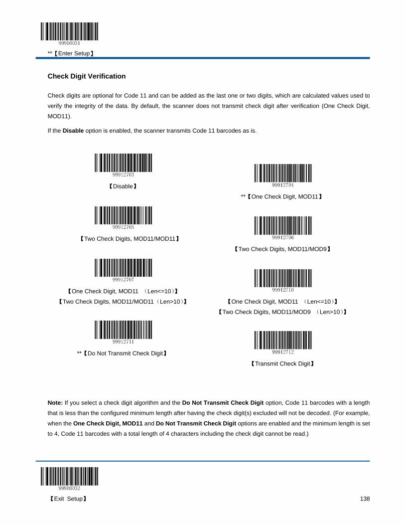
**【Enter Setup】
【Exit Setup】 138
Check Digit Verification
Check digits are optional for Code 11 and can be added as the last one or two digits, which are calculated values used to
verify the integrity of the data. By default, the scanner does not transmit check digit after verification (One Check Digit,
MOD11).
If the Disable option is enabled, the scanner transmits Code 11 barcodes as is.
【Disable】
**【One Check Digit, MOD11】
【Two Check Digits, MOD11/MOD11】
【Two Check Digits, MOD11/MOD9】
【One Check Digit, MOD11 (Len<=10)】
【Two Check Digits, MOD11/MOD11(Len>10)】
【One Check Digit, MOD11 (Len<=10)】
【Two Check Digits, MOD11/MOD9 (Len>10)】
**【Do Not Transmit Check Digit】
【Transmit Check Digit】
Note: If you select a check digit algorithm and the Do Not Transmit Check Digit option, Code 11 barcodes with a length
that is less than the configured minimum length after having the check digit(s) excluded will not be decoded. (For example,
when the One Check Digit, MOD11 and Do Not Transmit Check Digit options are enabled and the minimum length is set
to 4, Code 11 barcodes with a total length of 4 characters including the check digit cannot be read.)
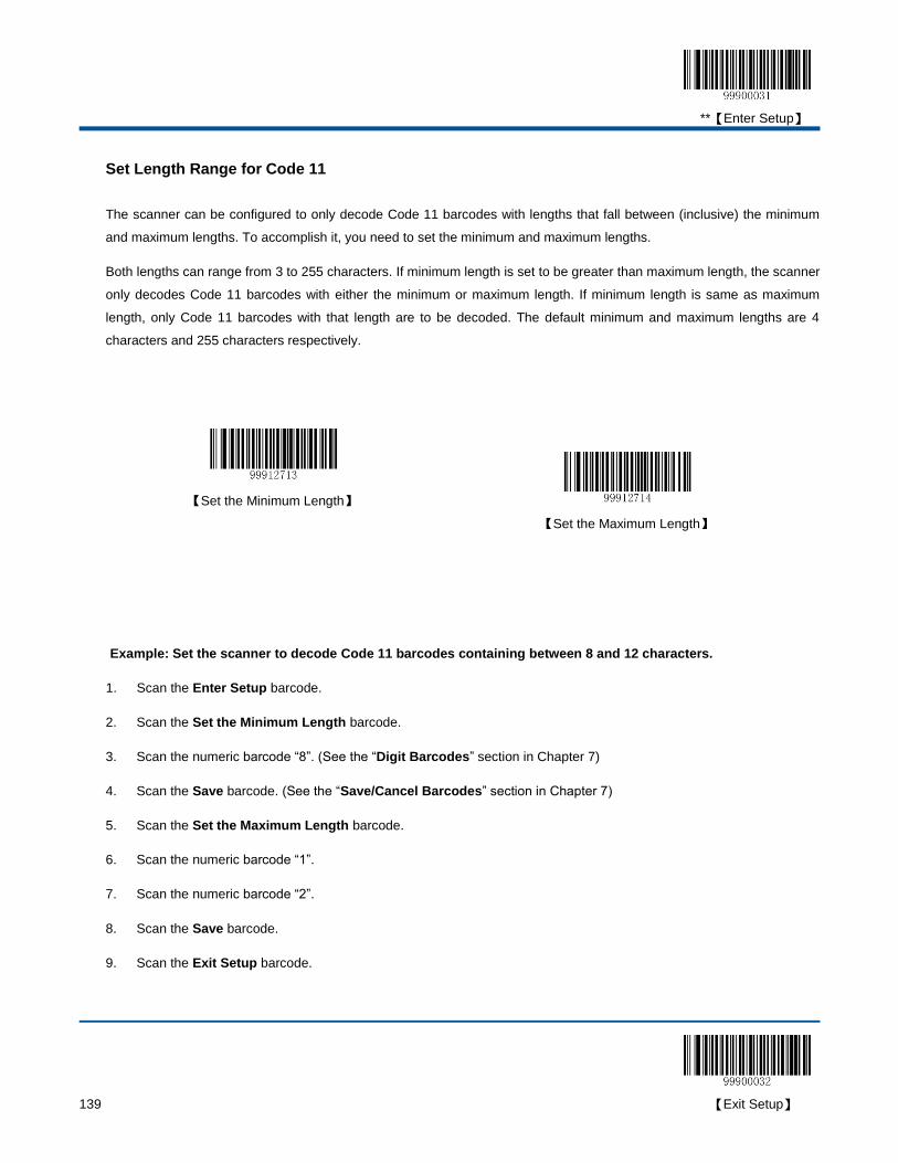
**【Enter Setup】
139 【Exit Setup】
Set Length Range for Code 11
The scanner can be configured to only decode Code 11 barcodes with lengths that fall between (inclusive) the minimum
and maximum lengths. To accomplish it, you need to set the minimum and maximum lengths.
Both lengths can range from 3 to 255 characters. If minimum length is set to be greater than maximum length, the scanner
only decodes Code 11 barcodes with either the minimum or maximum length. If minimum length is same as maximum
length, only Code 11 barcodes with that length are to be decoded. The default minimum and maximum lengths are 4
characters and 255 characters respectively.
【Set the Minimum Length】
【Set the Maximum Length】
Example: Set the scanner to decode Code 11 barcodes containing between 8 and 12 characters.
1. Scan the Enter Setup barcode.
2. Scan the Set the Minimum Length barcode.
3. Scan the numeric barcode “8”. (See the “Digit Barcodes” section in Chapter 7)
4. Scan the Save barcode. (See the “Save/Cancel Barcodes” section in Chapter 7)
5. Scan the Set the Maximum Length barcode.
6. Scan the numeric barcode “1”.
7. Scan the numeric barcode “2”.
8. Scan the Save barcode.
9. Scan the Exit Setup barcode.
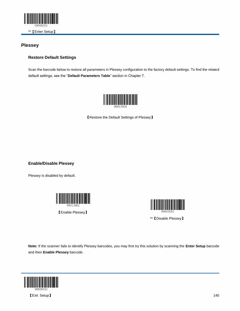
**【Enter Setup】
【Exit Setup】 140
Plessey
Restore Default Settings
Scan the barcode below to restore all parameters in Plessey configuration to the factory default settings. To find the related
default settings, see the “Default Parameters Table” section in Chapter 7.
【Restore the Default Settings of Plessey】
Enable/Disable Plessey
Plessey is disabled by default.
【Enable Plessey】
**【Disable Plessey】
Note: If the scanner fails to identify Plessey barcodes, you may first try this solution by scanning the Enter Setup barcode
and then Enable Plessey barcode.

**【Enter Setup】
141 【Exit Setup】
Set Code ID
Code ID can only consist of one or two English letters. See the “Code ID Table” section in Chapter 7 to find the default
Code ID for Plessey.
To set the Code ID, scan the Set Code ID for Plessey barcode, the numeric barcodes corresponding to the hexadecimal
value of a desired ID and the Save barcode.
【Set Code ID for Plessey】
Example: Set the Code ID of Plessey to “p” (its hexadecimal value is 0x70)
1. Scan the Enter Setup barcode.
2. Scan the Set Code ID for Plessey barcode.
3. Scan the programming barcodes for “7” and “0”. (See the “Digit Barcodes” section in Chapter 7)
4. Scan the Save barcode. (See the “Save/Cancel Barcodes” section in Chapter 7)
5. Scan the Exit Setup barcode.
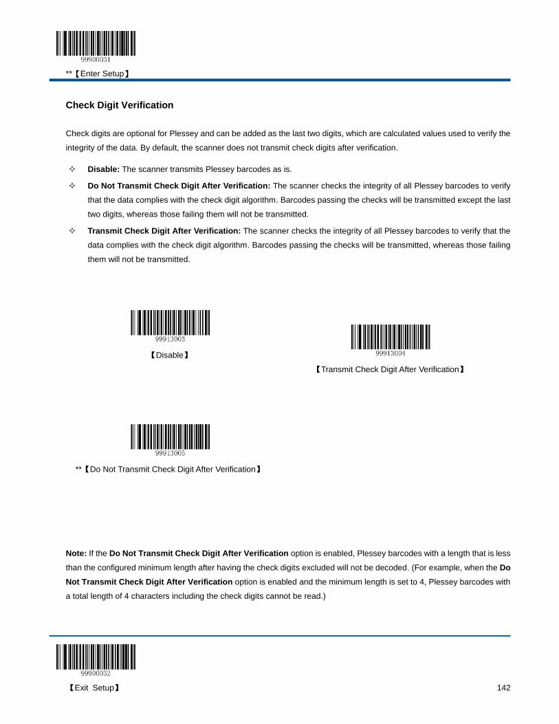
**【Enter Setup】
【Exit Setup】 142
Check Digit Verification
Check digits are optional for Plessey and can be added as the last two digits, which are calculated values used to verify the
integrity of the data. By default, the scanner does not transmit check digits after verification.
Disable: The scanner transmits Plessey barcodes as is.
Do Not Transmit Check Digit After Verification: The scanner checks the integrity of all Plessey barcodes to verify
that the data complies with the check digit algorithm. Barcodes passing the checks will be transmitted except the last
two digits, whereas those failing them will not be transmitted.
Transmit Check Digit After Verification: The scanner checks the integrity of all Plessey barcodes to verify that the
data complies with the check digit algorithm. Barcodes passing the checks will be transmitted, whereas those failing
them will not be transmitted.
Note: If the Do Not Transmit Check Digit After Verification option is enabled, Plessey barcodes with a length that is less
than the configured minimum length after having the check digits excluded will not be decoded. (For example, when the Do
Not Transmit Check Digit After Verification option is enabled and the minimum length is set to 4, Plessey barcodes with
a total length of 4 characters including the check digits cannot be read.)
【Disable】
【Transmit Check Digit After Verification】
**【Do Not Transmit Check Digit After Verification】
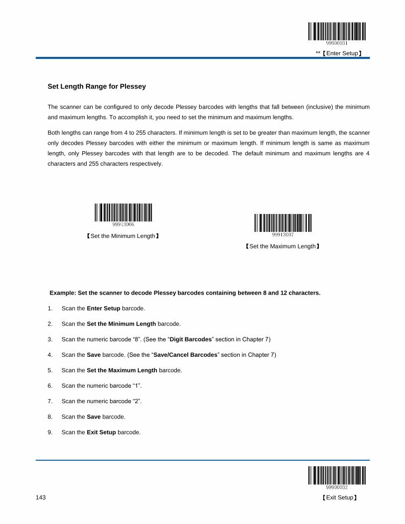
**【Enter Setup】
143 【Exit Setup】
Set Length Range for Plessey
The scanner can be configured to only decode Plessey barcodes with lengths that fall between (inclusive) the minimum
and maximum lengths. To accomplish it, you need to set the minimum and maximum lengths.
Both lengths can range from 4 to 255 characters. If minimum length is set to be greater than maximum length, the scanner
only decodes Plessey barcodes with either the minimum or maximum length. If minimum length is same as maximum
length, only Plessey barcodes with that length are to be decoded. The default minimum and maximum lengths are 4
characters and 255 characters respectively.
【Set the Minimum Length】
【Set the Maximum Length】
Example: Set the scanner to decode Plessey barcodes containing between 8 and 12 characters.
1. Scan the Enter Setup barcode.
2. Scan the Set the Minimum Length barcode.
3. Scan the numeric barcode “8”. (See the “Digit Barcodes” section in Chapter 7)
4. Scan the Save barcode. (See the “Save/Cancel Barcodes” section in Chapter 7)
5. Scan the Set the Maximum Length barcode.
6. Scan the numeric barcode “1”.
7. Scan the numeric barcode “2”.
8. Scan the Save barcode.
9. Scan the Exit Setup barcode.

**【Enter Setup】
【Exit Setup】 144
MSI-Plessey
Restore Default Settings
Scan the barcode below to restore all parameters in MSI-Plessey configuration to the factory default settings. To find the
related default settings, see the “Default Parameters Table” section in Chapter 7.
【Restore the Default Settings of MSI-Plessey】
Enable/Disable MSI-Plessey
MSI-Plessey is disabled by default.
【Enable MSI-Plessey】
**【Disable MSI-Plessey】
Note: If the scanner fails to identify MSI-Plessey barcodes, you may first try this solution by scanning the Enter Setup
barcode and then Enable MSI-Plessey barcode.

**【Enter Setup】
145 【Exit Setup】
Set Code ID
Code ID can only consist of one or two English letters. See the “Code ID Table” section in Chapter 7 to find the default
Code ID for MSI-Plessey.
To set the Code ID, scan the Set Code ID for MSI-Plessey barcode, the numeric barcodes corresponding to the
hexadecimal value of a desired ID and the Save barcode.
【Set Code ID for MSI-Plessey】
Example: Set the Code ID of MSI-Plessey to “p” (its hexadecimal value is 0x70)
1. Scan the Enter Setup barcode.
2. Scan the Set Code ID for MSI-Plessey barcode.
3. Scan the numeric barcodes “7” and “0”. (See the “Digit Barcodes” section in Chapter 7)
4. Scan the Save barcode. (See the “Save/Cancel Barcodes” section in Chapter 7)
5. Scan the Exit Setup barcode.
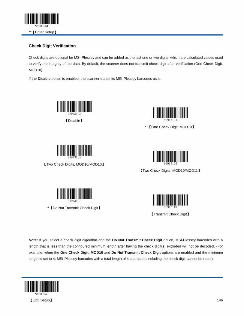
**【Enter Setup】
【Exit Setup】 146
Check Digit Verification
Check digits are optional for MSI-Plessey and can be added as the last one or two digits, which are calculated values used
to verify the integrity of the data. By default, the scanner does not transmit check digit after verification (One Check Digit,
MOD10).
If the Disable option is enabled, the scanner transmits MSI-Plessey barcodes as is.
【Disable】
**【One Check Digit, MOD10】
【Two Check Digits, MOD10/MOD10】
【Two Check Digits, MOD10/MOD11】
**【Do Not Transmit Check Digit】
【Transmit Check Digit】
Note: If you select a check digit algorithm and the Do Not Transmit Check Digit option, MSI-Plessey barcodes with a
length that is less than the configured minimum length after having the check digit(s) excluded will not be decoded. (For
example, when the One Check Digit, MOD10 and Do Not Transmit Check Digit options are enabled and the minimum
length is set to 4, MSI-Plessey barcodes with a total length of 4 characters including the check digit cannot be read.)

**【Enter Setup】
147 【Exit Setup】
Set Length Range for MSI-Plessey
The scanner can be configured to only decode MSI-Plessey barcodes with lengths that fall between (inclusive) the
minimum and maximum lengths. To accomplish it, you need to set the minimum and maximum lengths.
Both lengths can range from 3 to 255 characters. If minimum length is set to be greater than maximum length, the scanner
only decodes MSI-Plessey barcodes with either the minimum or maximum length. If minimum length is same as maximum
length, only MSI-Plessey barcodes with that length are to be decoded. The default minimum and maximum lengths are 4
characters and 255 characters respectively.
【Set the Minimum Length】
【Set the Maximum Length】
Example: Set the scanner to decode MSI-Plessey barcodes containing between 8 and 12 characters.
1. Scan the Enter Setup barcode.
2. Scan the Set the Minimum Length barcode.
3. Scan the numeric barcode “8”. (See the “Digit Barcodes” section in Chapter 7)
4. Scan the Save barcode. (See the “Save/Cancel Barcodes” section in Chapter 7)
5. Scan the Set the Maximum Length barcode.
6. Scan the numeric barcode “1”.
7. Scan the numeric barcode “2”.
8. Scan the Save barcode.
9. Scan the Exit Setup barcode.

**【Enter Setup】
【Exit Setup】 148
GS1 Databar
Restore Default Settings
Scan the barcode below to restore all parameters in GS1 Databar configuration to the factory default settings. To find the
related default settings, see the “Default Parameters Table” section in Chapter 7.
【Restore the Default Settings of GS1 Databar】
Enable/Disable GS1 Databar
GS1 Databar is enabled by default.
**【Enable GS1 Databar】
【Disable GS1 Databar】
Note: If the scanner fails to identify GS1 Databar barcodes, you may first try this solution by scanning the Enter Setup
barcode and then Enable GS1 Databar barcode.

**【Enter Setup】
149 【Exit Setup】
Set Code ID
Code ID can only consist of one or two English letters. See the “Code ID Table” section in Chapter 7 to find the default
Code ID for GS1 Databar.
To set the Code ID, scan the Set Code ID for GS1 Databar barcode, the numeric barcodes corresponding to the
hexadecimal value of a desired ID and the Save barcode.
【Set Code ID for GS1 Databar】
Example: Set the Code ID of GS1 Databar to “p” (its hexadecimal value is 0x70)
1. Scan the Enter Setup barcode.
2. Scan the Set Code ID for GS1 Databar barcode.
3. Scan the numeric barcodes “7” and “0”. (See the “Digit Barcodes” section in Chapter 7)
4. Scan the Save barcode. (See the “Save/Cancel Barcodes” section in Chapter 7)
5. Scan the Exit Setup barcode.
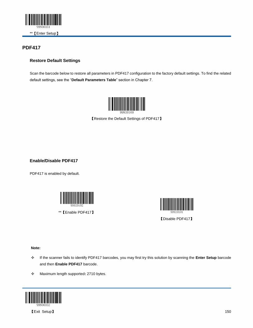
**【Enter Setup】
【Exit Setup】 150
PDF417
Restore Default Settings
Scan the barcode below to restore all parameters in PDF417 configuration to the factory default settings. To find the related
default settings, see the “Default Parameters Table” section in Chapter 7.
【Restore the Default Settings of PDF417】
Enable/Disable PDF417
PDF417 is enabled by default.
**【Enable PDF417】
【Disable PDF417】
Note:
If the scanner fails to identify PDF417 barcodes, you may first try this solution by scanning the Enter Setup barcode
and then Enable PDF417 barcode.
Maximum length supported: 2710 bytes.
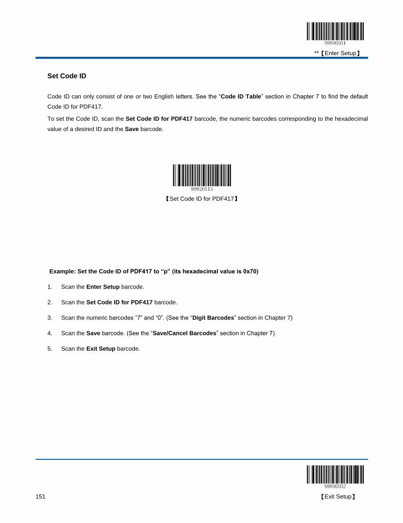
**【Enter Setup】
151 【Exit Setup】
Set Code ID
Code ID can only consist of one or two English letters. See the “Code ID Table” section in Chapter 7 to find the default
Code ID for PDF417.
To set the Code ID, scan the Set Code ID for PDF417 barcode, the numeric barcodes corresponding to the hexadecimal
value of a desired ID and the Save barcode.
【Set Code ID for PDF417】
Example: Set the Code ID of PDF417 to “p” (its hexadecimal value is 0x70)
1. Scan the Enter Setup barcode.
2. Scan the Set Code ID for PDF417 barcode.
3. Scan the numeric barcodes “7” and “0”. (See the “Digit Barcodes” section in Chapter 7)
4. Scan the Save barcode. (See the “Save/Cancel Barcodes” section in Chapter 7)
5. Scan the Exit Setup barcode.
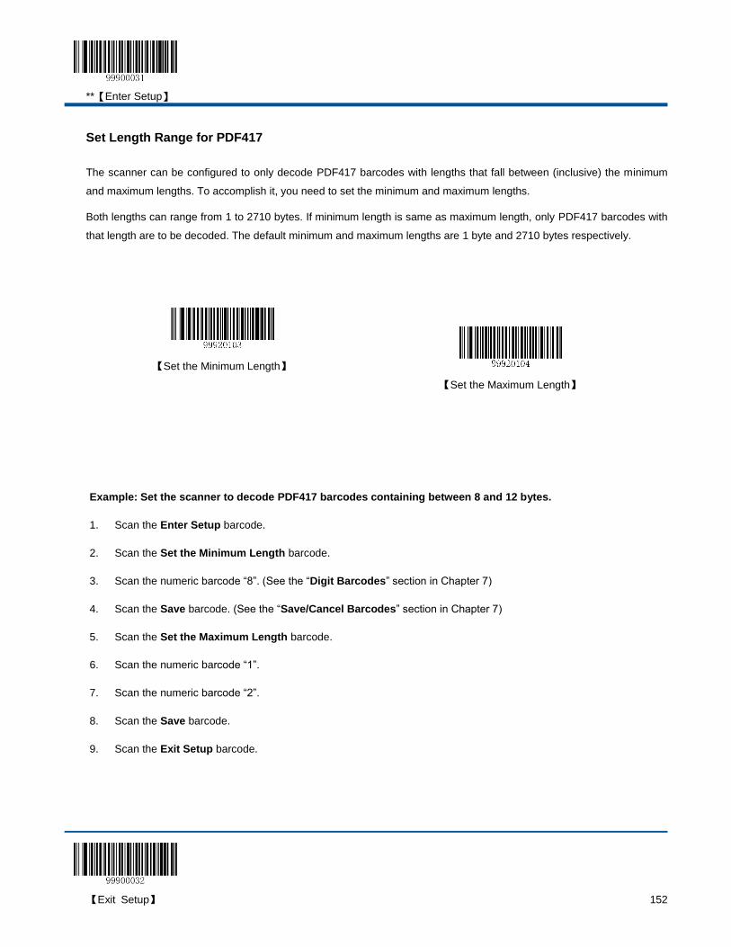
**【Enter Setup】
【Exit Setup】 152
Set Length Range for PDF417
The scanner can be configured to only decode PDF417 barcodes with lengths that fall between (inclusive) the minimum
and maximum lengths. To accomplish it, you need to set the minimum and maximum lengths.
Both lengths can range from 1 to 2710 bytes. If minimum length is same as maximum length, only PDF417 barcodes with
that length are to be decoded. The default minimum and maximum lengths are 1 byte and 2710 bytes respectively.
【Set the Minimum Length】
【Set the Maximum Length】
Example: Set the scanner to decode PDF417 barcodes containing between 8 and 12 bytes.
1. Scan the Enter Setup barcode.
2. Scan the Set the Minimum Length barcode.
3. Scan the numeric barcode “8”. (See the “Digit Barcodes” section in Chapter 7)
4. Scan the Save barcode. (See the “Save/Cancel Barcodes” section in Chapter 7)
5. Scan the Set the Maximum Length barcode.
6. Scan the numeric barcode “1”.
7. Scan the numeric barcode “2”.
8. Scan the Save barcode.
9. Scan the Exit Setup barcode.
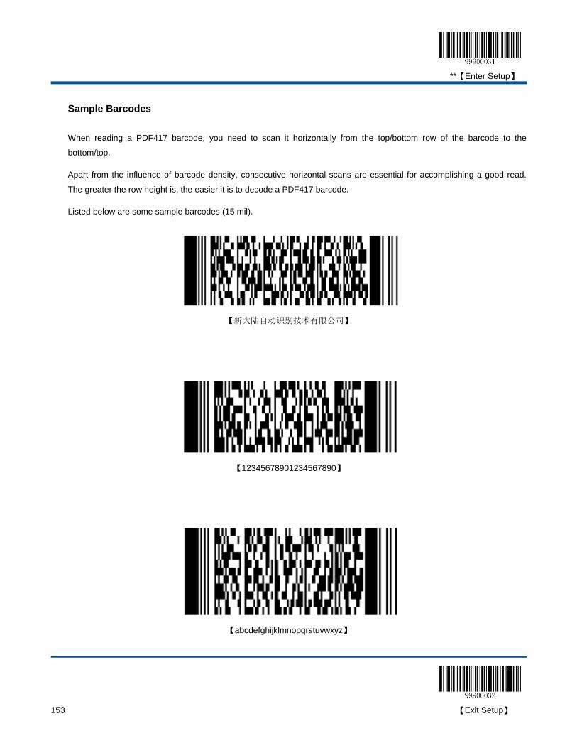
**【Enter Setup】
153 【Exit Setup】
Sample Barcodes
When reading a PDF417 barcode, you need to scan it horizontally from the top/bottom row of the barcode to the
bottom/top.
Apart from the influence of barcode density, consecutive horizontal scans are essential for accomplishing a good read.
The greater the row height is, the easier it is to decode a PDF417 barcode.
Listed below are some sample barcodes (15 mil).
【新大陆自动识别技术有限公司】
【12345678901234567890】
【abcdefghijklmnopqrstuvwxyz】

**【Enter Setup】
【Exit Setup】 154
MicroPDF417
Restore Default Settings
Scan the barcode below to restore all parameters in PDF417 configuration to the factory default settings. To find the related
default settings, see the “Default Parameters Table” section in Chapter 7.
【Restore the Default Settings of MicroPDF417】
Enable/Disable MicroPDF417
MicroPDF417 is disabled by default.
【Enable MicroPDF417】
**【Disable MicroPDF417】
Note:
If the scanner fails to identify MicroPDF417 barcodes, you may first try this solution by scanning the Enter Setup
barcode and then Enable MicroPDF417 barcode.
Maximum length supported: 366 bytes.
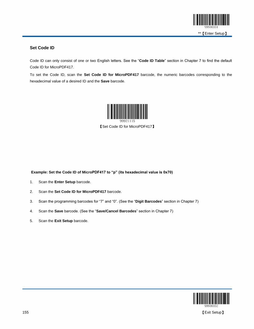
**【Enter Setup】
155 【Exit Setup】
Set Code ID
Code ID can only consist of one or two English letters. See the “Code ID Table” section in Chapter 7 to find the default
Code ID for MicroPDF417.
To set the Code ID, scan the Set Code ID for MicroPDF417 barcode, the numeric barcodes corresponding to the
hexadecimal value of a desired ID and the Save barcode.
【Set Code ID for MicroPDF417】
Example: Set the Code ID of MicroPDF417 to “p” (its hexadecimal value is 0x70)
1. Scan the Enter Setup barcode.
2. Scan the Set Code ID for MicroPDF417 barcode.
3. Scan the programming barcodes for “7” and “0”. (See the “Digit Barcodes” section in Chapter 7)
4. Scan the Save barcode. (See the “Save/Cancel Barcodes” section in Chapter 7)
5. Scan the Exit Setup barcode.
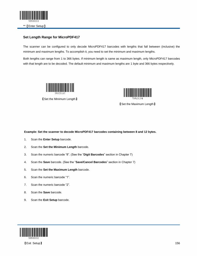
**【Enter Setup】
【Exit Setup】 156
Set Length Range for MicroPDF417
The scanner can be configured to only decode MicroPDF417 barcodes with lengths that fall between (inclusive) the
minimum and maximum lengths. To accomplish it, you need to set the minimum and maximum lengths.
Both lengths can range from 1 to 366 bytes. If minimum length is same as maximum length, only MicroPDF417 barcodes
with that length are to be decoded. The default minimum and maximum lengths are 1 byte and 366 bytes respectively.
【Set the Minimum Length】
【Set the Maximum Length】
Example: Set the scanner to decode MicroPDF417 barcodes containing between 8 and 12 bytes.
1. Scan the Enter Setup barcode.
2. Scan the Set the Minimum Length barcode.
3. Scan the numeric barcode “8”. (See the “Digit Barcodes” section in Chapter 7)
4. Scan the Save barcode. (See the “Save/Cancel Barcodes” section in Chapter 7)
5. Scan the Set the Maximum Length barcode.
6. Scan the numeric barcode “1”.
7. Scan the numeric barcode “2”.
8. Scan the Save barcode.
9. Scan the Exit Setup barcode.
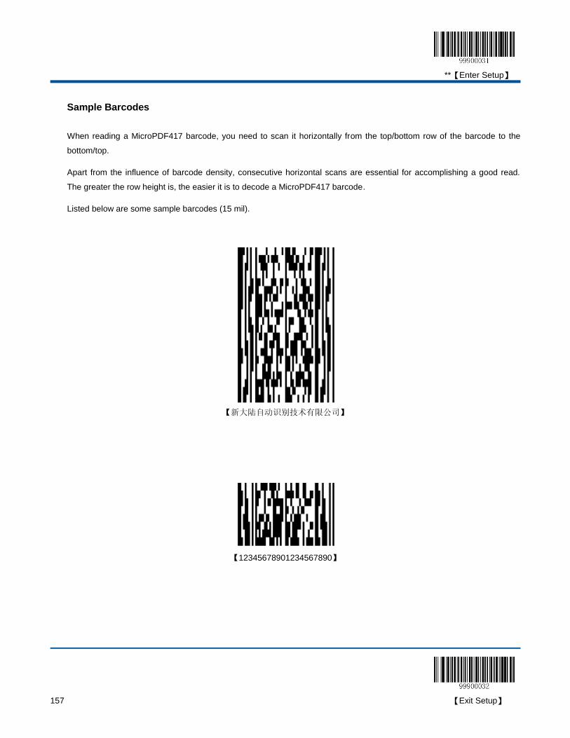
**【Enter Setup】
157 【Exit Setup】
Sample Barcodes
When reading a MicroPDF417 barcode, you need to scan it horizontally from the top/bottom row of the barcode to the
bottom/top.
Apart from the influence of barcode density, consecutive horizontal scans are essential for accomplishing a good read.
The greater the row height is, the easier it is to decode a MicroPDF417 barcode.
Listed below are some sample barcodes (15 mil).
【新大陆自动识别技术有限公司】
【12345678901234567890】

**【Enter Setup】
【Exit Setup】 158
【abcdefghijklmnopqrstuvwxyz】
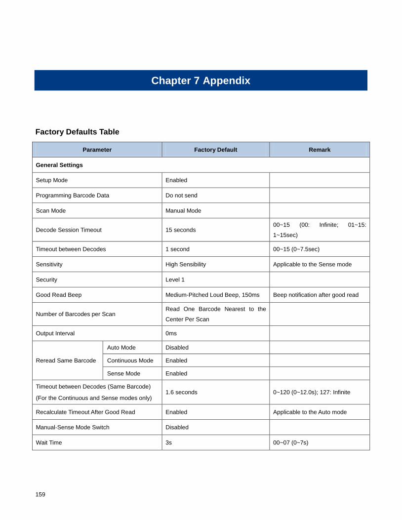
159
Chapter 7 Appendix
Factory Defaults Table
Parameter Factory Default Remark
General Settings
Setup Mode Enabled
Programming Barcode Data Do not send
Scan Mode Manual Mode
Decode Session Timeout 15 seconds 00~15 (00: Infinite; 01~15:
1~15sec)
Timeout between Decodes 1 second 00~15 (0~7.5sec)
Sensitivity High Sensibility Applicable to the Sense mode
Security Level 1
Good Read Beep Medium-Pitched Loud Beep, 150ms Beep notification after good read
Number of Barcodes per Scan Read One Barcode Nearest to the
Center Per Scan
Output Interval 0ms
Reread Same Barcode
Auto Mode Disabled
Continuous Mode Enabled
Sense Mode Enabled
Timeout between Decodes (Same Barcode)
(For the Continuous and Sense modes only) 1.6 seconds 0~120 (0~12.0s); 127: Infinite
Recalculate Timeout After Good Read Enabled Applicable to the Auto mode
Manual-Sense Mode Switch Disabled
Wait Time 3s 00~07 (0~7s)
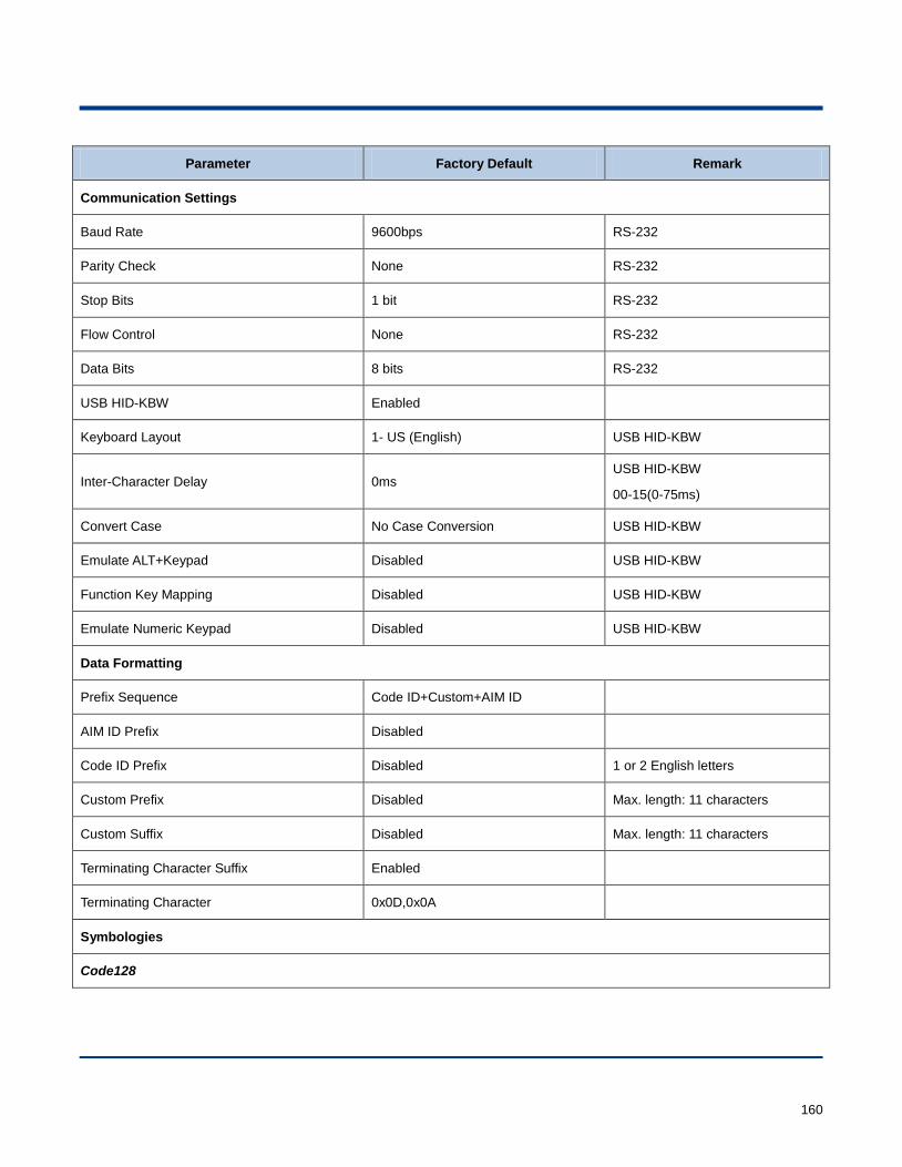
160
Parameter Factory Default Remark
Communication Settings
Baud Rate 9600bps RS-232
Parity Check None RS-232
Stop Bits 1 bit RS-232
Flow Control None RS-232
Data Bits 8 bits RS-232
USB HID-KBW Enabled
Keyboard Layout 1- US (English) USB HID-KBW
Inter-Character Delay 0ms USB HID-KBW
00-15(0-75ms)
Convert Case No Case Conversion USB HID-KBW
Emulate ALT+Keypad Disabled USB HID-KBW
Function Key Mapping Disabled USB HID-KBW
Emulate Numeric Keypad Disabled USB HID-KBW
Data Formatting
Prefix Sequence Code ID+Custom+AIM ID
AIM ID Prefix Disabled
Code ID Prefix Disabled 1 or 2 English letters
Custom Prefix Disabled Max. length: 11 characters
Custom Suffix Disabled Max. length: 11 characters
Terminating Character Suffix Enabled
Terminating Character 0x0D,0x0A
Symbologies
Code128
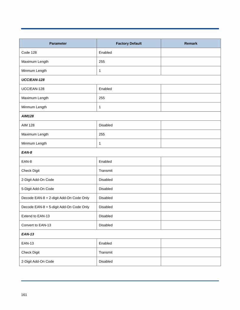
161
Parameter Factory Default Remark
Code 128 Enabled
Maximum Length 255
Minmum Length 1
UCC/EAN-128
UCC/EAN-128 Enabled
Maximum Length 255
Minmum Length 1
AIM128
AIM 128 Disabled
Maximum Length 255
Minmum Length 1
EAN-8
EAN-8 Enabled
Check Digit Transmit
2-Digit Add-On Code Disabled
5-Digit Add-On Code Disabled
Decode EAN-8 + 2-digit Add-On Code Only Disabled
Decode EAN-8 + 5-digit Add-On Code Only Disabled
Extend to EAN-13 Disabled
Convert to EAN-13 Disabled
EAN-13
EAN-13 Enabled
Check Digit Transmit
2-Digit Add-On Code Disabled
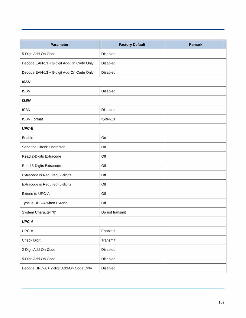
162
Parameter Factory Default Remark
5-Digit Add-On Code Disabled
Decode EAN-13 + 2-digit Add-On Code Only Disabled
Decode EAN-13 + 5-digit Add-On Code Only Disabled
ISSN
ISSN Disabled
ISBN
ISBN Disabled
ISBN Format ISBN-13
UPC-E
Enable On
Send the Check Character On
Read 2-Digits Extracode Off
Read 5-Digits Extracode Off
Extracode is Required, 2-digits Off
Extracode is Required, 5-digits Off
Extend to UPC-A Off
Type is UPC-A when Extend Off
System Character “0” Do not transmit
UPC-A
UPC-A Enabled
Check Digit Transmit
2-Digit Add-On Code Disabled
5-Digit Add-On Code Disabled
Decode UPC-A + 2-digit Add-On Code Only Disabled
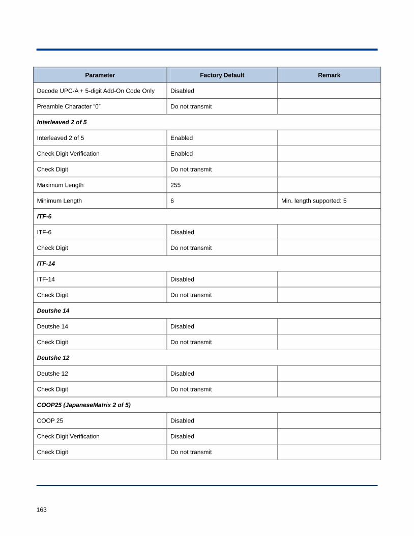
163
Parameter Factory Default Remark
Decode UPC-A + 5-digit Add-On Code Only Disabled
Preamble Character “0” Do not transmit
Interleaved 2 of 5
Interleaved 2 of 5 Enabled
Check Digit Verification Enabled
Check Digit Do not transmit
Maximum Length 255
Minimum Length 6 Min. length supported: 5
ITF-6
ITF-6 Disabled
Check Digit Do not transmit
ITF-14
ITF-14 Disabled
Check Digit Do not transmit
Deutshe 14
Deutshe 14 Disabled
Check Digit Do not transmit
Deutshe 12
Deutshe 12 Disabled
Check Digit Do not transmit
COOP25 (JapaneseMatrix 2 of 5)
COOP 25 Disabled
Check Digit Verification Disabled
Check Digit Do not transmit
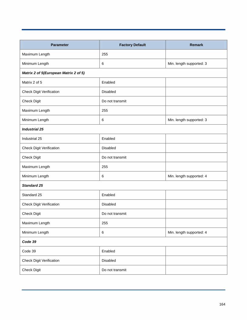
164
Parameter Factory Default Remark
Maximum Length 255
Minimum Length 6 Min. length supported: 3
Matrix 2 of 5(European Matrix 2 of 5)
Matrix 2 of 5 Enabled
Check Digit Verification Disabled
Check Digit Do not transmit
Maximum Length 255
Minimum Length 6 Min. length supported: 3
Industrial 25
Industrial 25 Enabled
Check Digit Verification Disabled
Check Digit Do not transmit
Maximum Length 255
Minimum Length 6 Min. length supported: 4
Standard 25
Standard 25 Enabled
Check Digit Verification Disabled
Check Digit Do not transmit
Maximum Length 255
Minimum Length 6 Min. length supported: 4
Code 39
Code 39 Enabled
Check Digit Verification Disabled
Check Digit Do not transmit
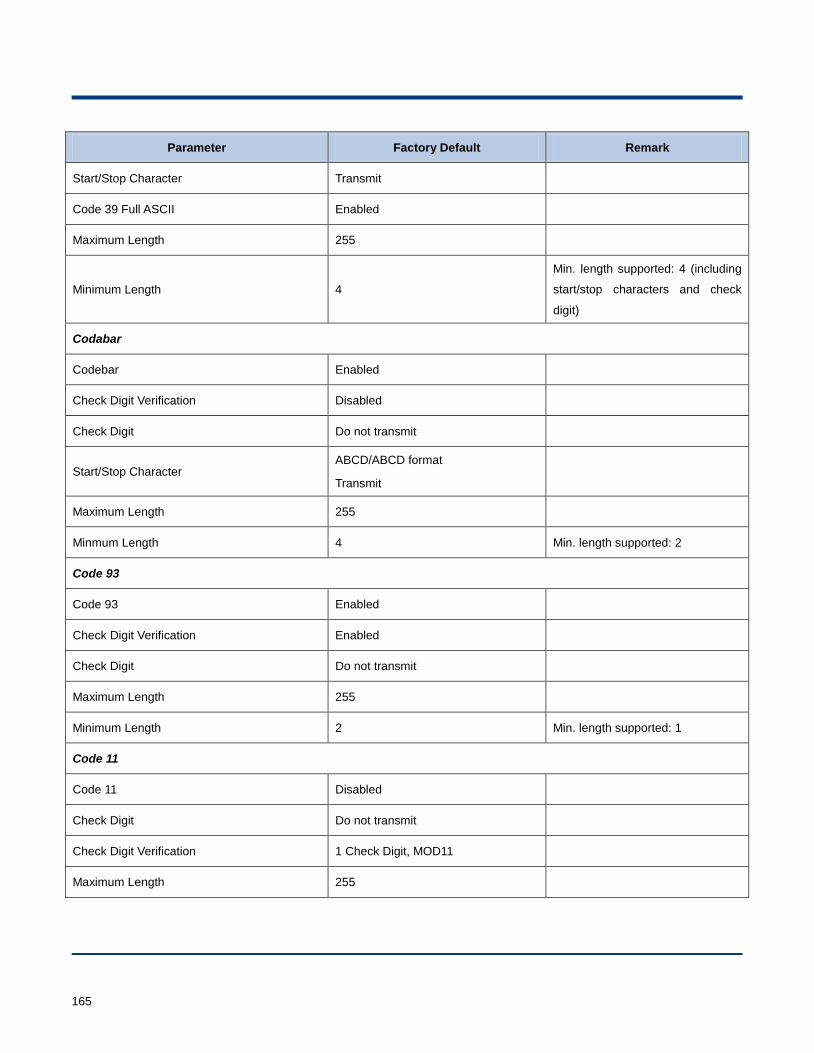
165
Parameter Factory Default Remark
Start/Stop Character Transmit
Code 39 Full ASCII Enabled
Maximum Length 255
Minimum Length 4
Min. length supported: 4 (including
start/stop characters and check
digit)
Codabar
Codebar Enabled
Check Digit Verification Disabled
Check Digit Do not transmit
Start/Stop Character ABCD/ABCD format
Transmit
Maximum Length 255
Minmum Length 4 Min. length supported: 2
Code 93
Code 93 Enabled
Check Digit Verification Enabled
Check Digit Do not transmit
Maximum Length 255
Minimum Length 2 Min. length supported: 1
Code 11
Code 11 Disabled
Check Digit Do not transmit
Check Digit Verification 1 Check Digit, MOD11
Maximum Length 255
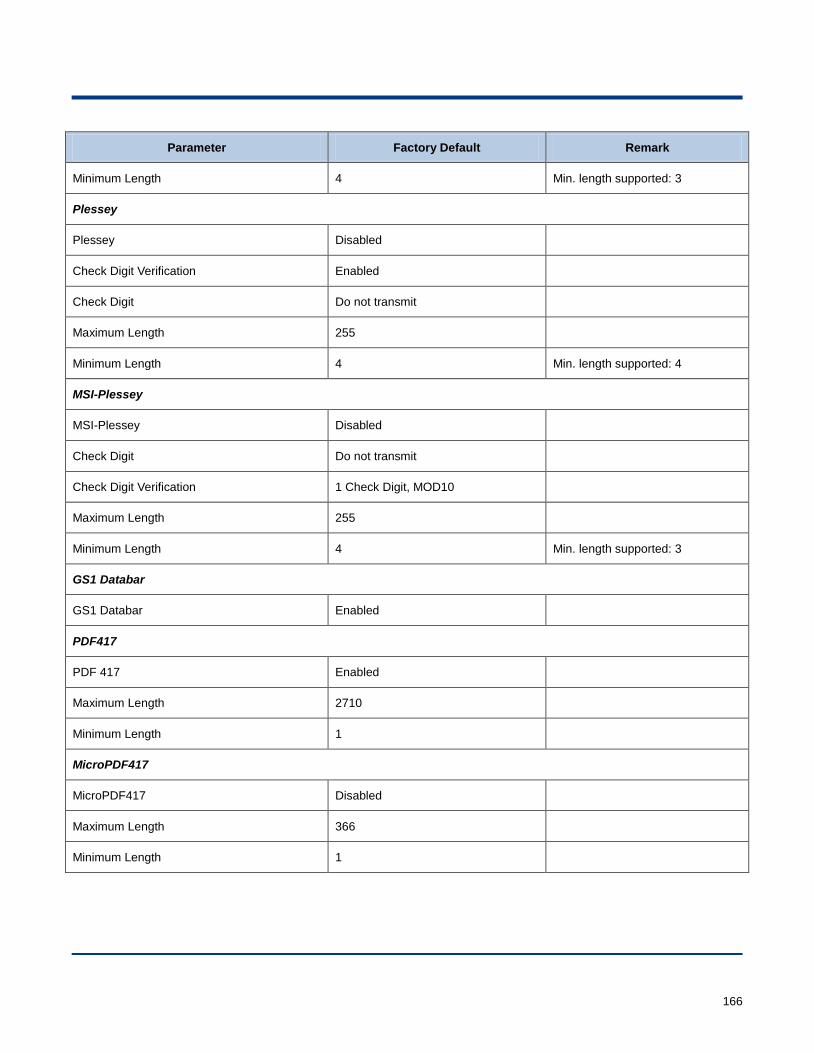
166
Parameter Factory Default Remark
Minimum Length 4 Min. length supported: 3
Plessey
Plessey Disabled
Check Digit Verification Enabled
Check Digit Do not transmit
Maximum Length 255
Minimum Length 4 Min. length supported: 4
MSI-Plessey
MSI-Plessey Disabled
Check Digit Do not transmit
Check Digit Verification 1 Check Digit, MOD10
Maximum Length 255
Minimum Length 4 Min. length supported: 3
GS1 Databar
GS1 Databar Enabled
PDF417
PDF 417 Enabled
Maximum Length 2710
Minimum Length 1
MicroPDF417
MicroPDF417 Disabled
Maximum Length 366
Minimum Length 1
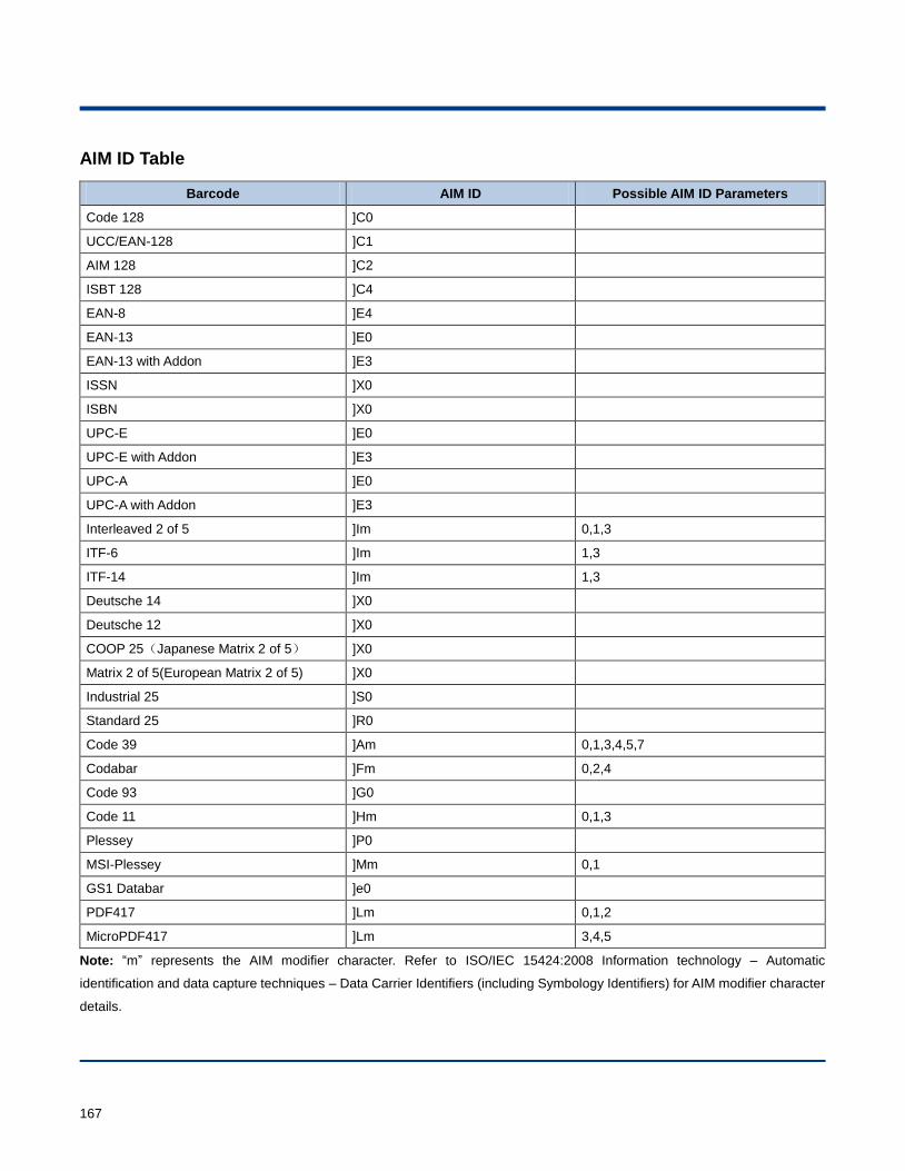
167
AIM ID Table
Barcode AIM ID Possible AIM ID Parameters
Code 128 ]C0
UCC/EAN-128 ]C1
AIM 128 ]C2
ISBT 128 ]C4
EAN-8 ]E4
EAN-13 ]E0
EAN-13 with Addon ]E3
ISSN ]X0
ISBN ]X0
UPC-E ]E0
UPC-E with Addon ]E3
UPC-A ]E0
UPC-A with Addon ]E3
Interleaved 2 of 5 ]Im 0,1,3
ITF-6 ]Im 1,3
ITF-14 ]Im 1,3
Deutsche 14 ]X0
Deutsche 12 ]X0
COOP 25(Japanese Matrix 2 of 5) ]X0
Matrix 2 of 5(European Matrix 2 of 5) ]X0
Industrial 25 ]S0
Standard 25 ]R0
Code 39 ]Am 0,1,3,4,5,7
Codabar ]Fm 0,2,4
Code 93 ]G0
Code 11 ]Hm 0,1,3
Plessey ]P0
MSI-Plessey ]Mm 0,1
GS1 Databar ]e0
PDF417 ]Lm 0,1,2
MicroPDF417 ]Lm 3,4,5
Note: “m” represents the AIM modifier character. Refer to ISO/IEC 15424:2008 Information technology – Automatic
identification and data capture techniques – Data Carrier Identifiers (including Symbology Identifiers) for AIM modifier character
details.
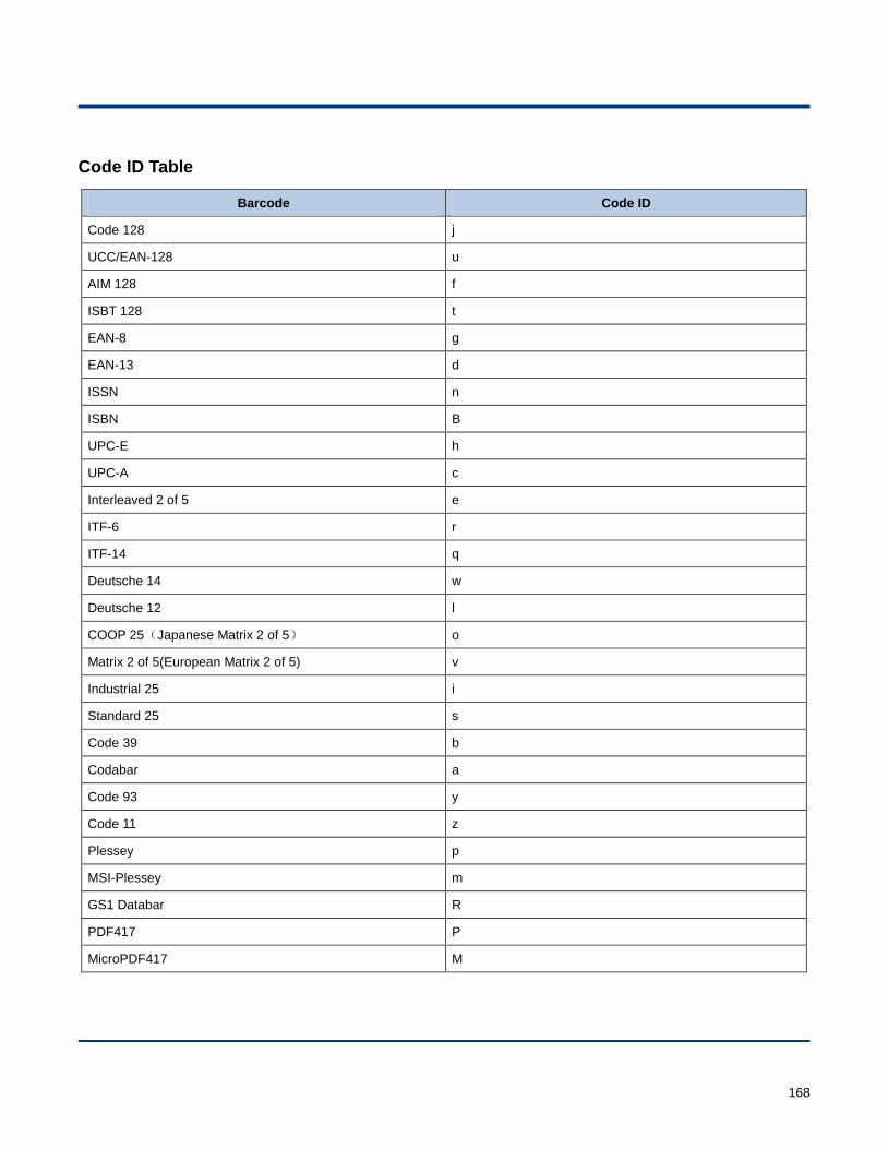
168
Code ID Table
Barcode Code ID
Code 128 j
UCC/EAN-128 u
AIM 128 f
ISBT 128 t
EAN-8 g
EAN-13 d
ISSN n
ISBN B
UPC-E h
UPC-A c
Interleaved 2 of 5 e
ITF-6 r
ITF-14 q
Deutsche 14 w
Deutsche 12 l
COOP 25(Japanese Matrix 2 of 5) o
Matrix 2 of 5(European Matrix 2 of 5) v
Industrial 25 i
Standard 25 s
Code 39 b
Codabar a
Code 93 y
Code 11 z
Plessey p
MSI-Plessey m
GS1 Databar R
PDF417 P
MicroPDF417 M
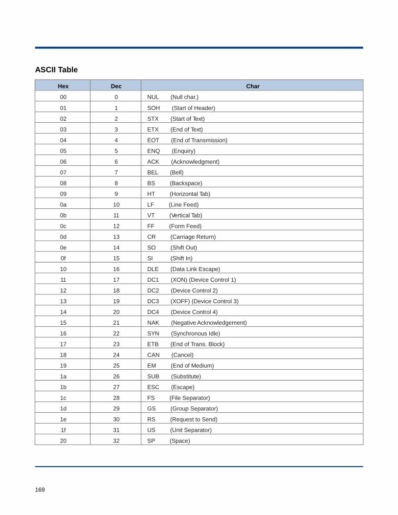
169
ASCII Table
Hex Dec Char
00 0 NUL (Null char.)
01 1 SOH (Start of Header)
02 2 STX (Start of Text)
03 3 ETX (End of Text)
04 4 EOT (End of Transmission)
05 5 ENQ (Enquiry)
06 6 ACK (Acknowledgment)
07 7 BEL (Bell)
08 8 BS (Backspace)
09 9 HT (Horizontal Tab)
0a 10 LF (Line Feed)
0b 11 VT (Vertical Tab)
0c 12 FF (Form Feed)
0d 13 CR (Carriage Return)
0e 14 SO (Shift Out)
0f 15 SI (Shift In)
10 16 DLE (Data Link Escape)
11 17 DC1 (XON) (Device Control 1)
12 18 DC2 (Device Control 2)
13 19 DC3 (XOFF) (Device Control 3)
14 20 DC4 (Device Control 4)
15 21 NAK (Negative Acknowledgement)
16 22 SYN (Synchronous Idle)
17 23 ETB (End of Trans. Block)
18 24 CAN (Cancel)
19 25 EM (End of Medium)
1a 26 SUB (Substitute)
1b 27 ESC (Escape)
1c 28 FS (File Separator)
1d 29 GS (Group Separator)
1e 30 RS (Request to Send)
1f 31 US (Unit Separator)
20 32 SP (Space)
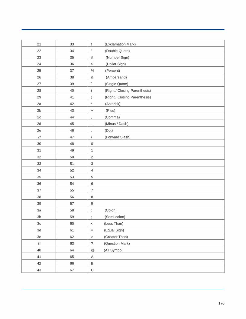
170
21 33 ! (Exclamation Mark)
22 34 " (Double Quote)
23 35 # (Number Sign)
24 36 $ (Dollar Sign)
25 37 % (Percent)
26 38 & (Ampersand)
27 39 ` (Single Quote)
28 40 ( (Right / Closing Parenthesis)
29 41 ) (Right / Closing Parenthesis)
2a 42 * (Asterisk)
2b 43 + (Plus)
2c 44 , (Comma)
2d 45 - (Minus / Dash)
2e 46 . (Dot)
2f 47 / (Forward Slash)
30 48 0
31 49 1
32 50 2
33 51 3
34 52 4
35 53 5
36 54 6
37 55 7
38 56 8
39 57 9
3a 58 : (Colon)
3b 59 ; (Semi-colon)
3c 60 < (Less Than)
3d 61 = (Equal Sign)
3e 62 > (Greater Than)
3f 63 ? (Question Mark)
40 64 @ (AT Symbol)
41 65 A
42 66 B
43 67 C
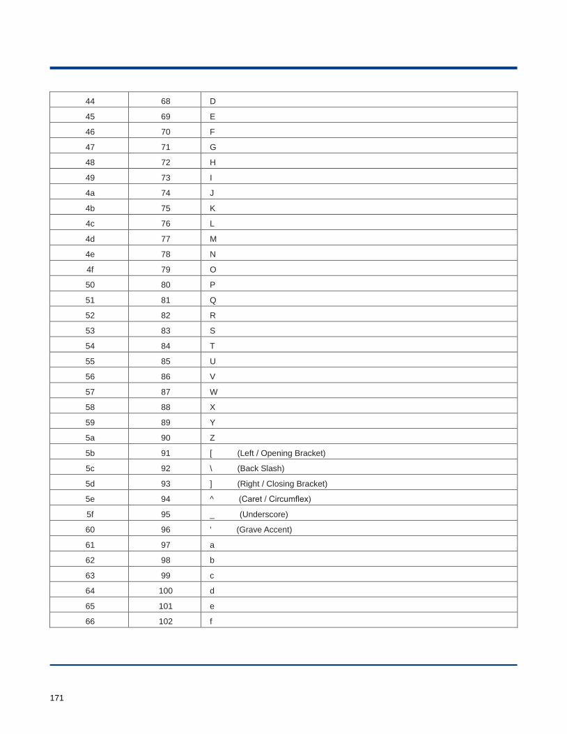
171
44 68 D
45 69 E
46 70 F
47 71 G
48 72 H
49 73 I
4a 74 J
4b 75 K
4c 76 L
4d 77 M
4e 78 N
4f 79 O
50 80 P
51 81 Q
52 82 R
53 83 S
54 84 T
55 85 U
56 86 V
57 87 W
58 88 X
59 89 Y
5a 90 Z
5b 91 [ (Left / Opening Bracket)
5c 92 \ (Back Slash)
5d 93 ] (Right / Closing Bracket)
5e 94 ^ (Caret / Circumflex)
5f 95 _ (Underscore)
60 96 ' (Grave Accent)
61 97 a
62 98 b
63 99 c
64 100 d
65 101 e
66 102 f
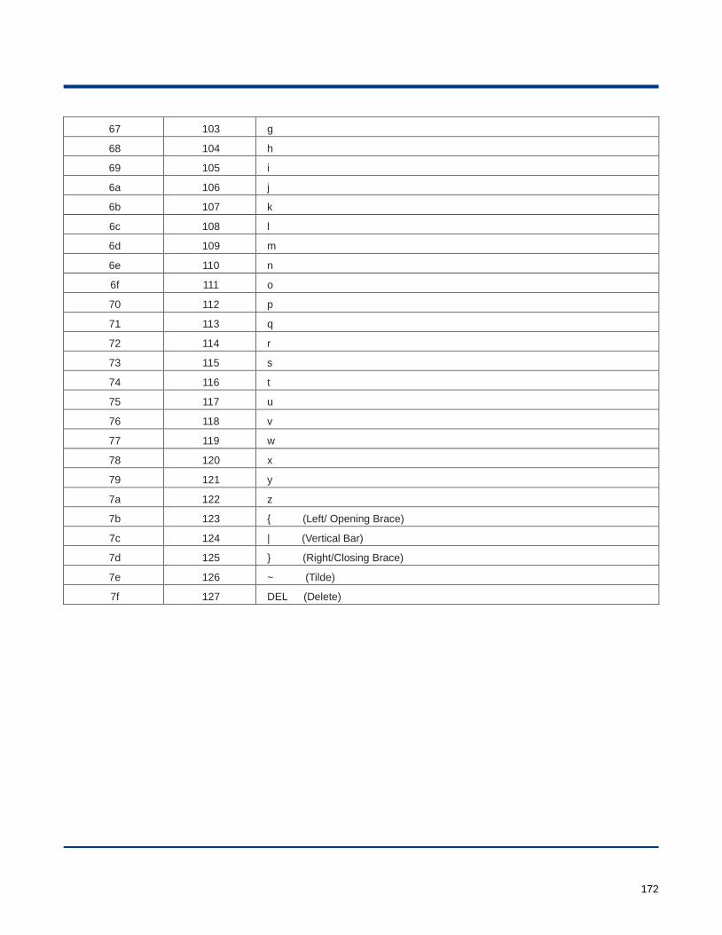
172
67 103 g
68 104 h
69 105 i
6a 106 j
6b 107 k
6c 108 l
6d 109 m
6e 110 n
6f 111 o
70 112 p
71 113 q
72 114 r
73 115 s
74 116 t
75 117 u
76 118 v
77 119 w
78 120 x
79 121 y
7a 122 z
7b 123 { (Left/ Opening Brace)
7c 124 | (Vertical Bar)
7d 125 } (Right/Closing Brace)
7e 126 ~ (Tilde)
7f 127 DEL (Delete)
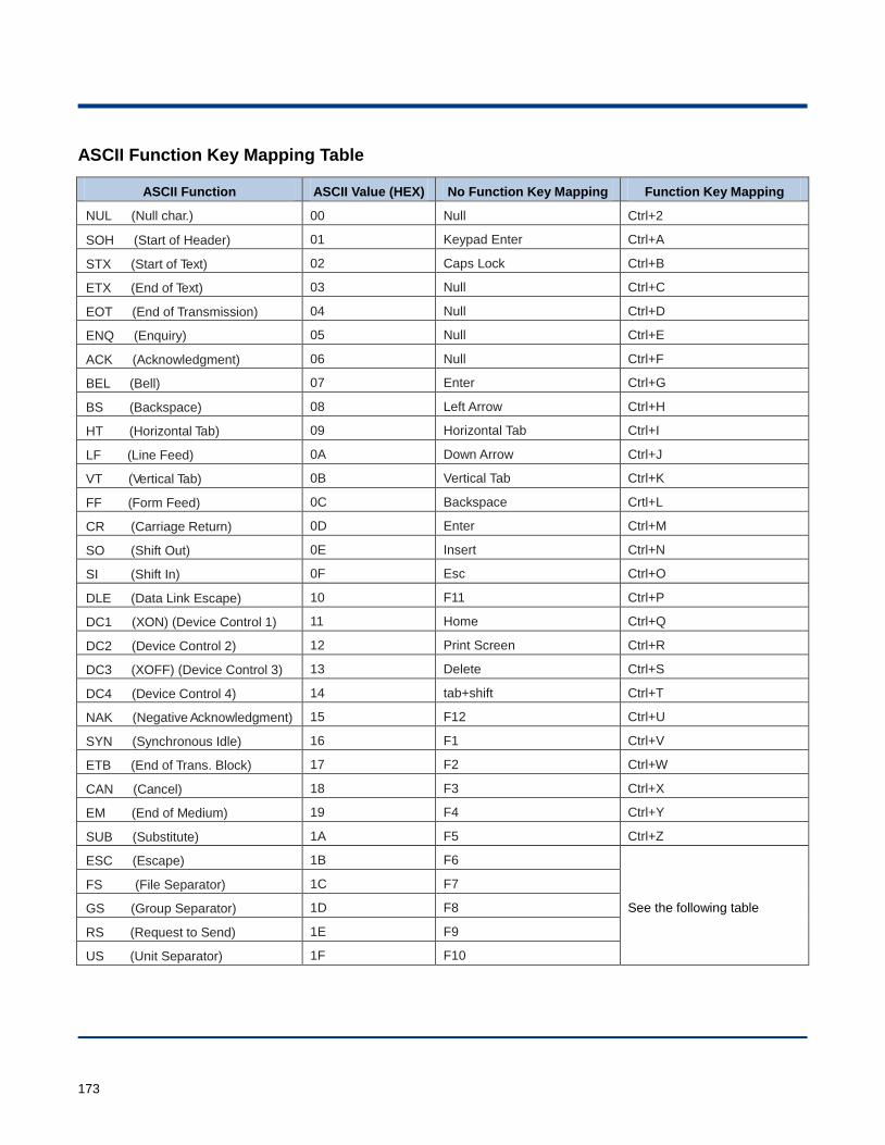
173
ASCII Function Key Mapping Table
ASCII Function ASCII Value (HEX) No Function Key Mapping Function Key Mapping
NUL (Null char.) 00 Null Ctrl+2
SOH (Start of Header) 01 Keypad Enter Ctrl+A
STX (Start of Text) 02 Caps Lock Ctrl+B
ETX (End of Text) 03 Null Ctrl+C
EOT (End of Transmission) 04 Null Ctrl+D
ENQ (Enquiry) 05 Null Ctrl+E
ACK (Acknowledgment) 06 Null Ctrl+F
BEL (Bell) 07 Enter Ctrl+G
BS (Backspace) 08 Left Arrow Ctrl+H
HT (Horizontal Tab) 09 Horizontal Tab Ctrl+I
LF (Line Feed) 0A Down Arrow Ctrl+J
VT (Vertical Tab) 0B Vertical Tab Ctrl+K
FF (Form Feed) 0C Backspace Crtl+L
CR (Carriage Return) 0D Enter Ctrl+M
SO (Shift Out) 0E Insert Ctrl+N
SI (Shift In) 0F Esc Ctrl+O
DLE (Data Link Escape) 10 F11 Ctrl+P
DC1 (XON) (Device Control 1) 11 Home Ctrl+Q
DC2 (Device Control 2) 12 Print Screen Ctrl+R
DC3 (XOFF) (Device Control 3) 13 Delete Ctrl+S
DC4 (Device Control 4) 14 tab+shift Ctrl+T
NAK (Negative Acknowledgment) 15 F12 Ctrl+U
SYN (Synchronous Idle) 16 F1 Ctrl+V
ETB (End of Trans. Block) 17 F2 Ctrl+W
CAN (Cancel) 18 F3 Ctrl+X
EM (End of Medium) 19 F4 Ctrl+Y
SUB (Substitute) 1A F5 Ctrl+Z
ESC (Escape) 1B F6
See the following table
FS (File Separator) 1C F7
GS (Group Separator) 1D F8
RS (Request to Send) 1E F9
US (Unit Separator) 1F F10
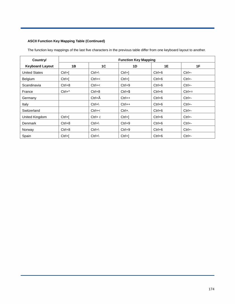
174
ASCII Function Key Mapping Table (Continued)
The function key mappings of the last five characters in the previous table differ from one keyboard layout to another.
Country/
Keyboard Layout
Function Key Mapping
1B 1C 1D 1E 1F
United States Ctrl+[ Ctrl+\ Ctrl+] Ctrl+6 Ctrl+-
Belgium Ctrl+[ Ctrl+< Ctrl+] Ctrl+6 Ctrl+-
Scandinavia Ctrl+8 Ctrl+< Ctrl+9 Ctrl+6 Ctrl+-
France Ctrl+^ Ctrl+8 Ctrl+$ Ctrl+6 Ctrl+=
Germany Ctrl+Ã Ctrl++ Ctrl+6 Ctrl+-
Italy Ctrl+\ Ctrl++ Ctrl+6 Ctrl+-
Switzerland Ctrl+< Ctrl+. Ctrl+6 Ctrl+-
United Kingdom Ctrl+[ Ctrl+¢ Ctrl+] Ctrl+6 Ctrl+-
Denmark Ctrl+8 Ctrl+\ Ctrl+9 Ctrl+6 Ctrl+-
Norway Ctrl+8 Ctrl+\ Ctrl+9 Ctrl+6 Ctrl+-
Spain Ctrl+[ Ctrl+\ Ctrl+] Ctrl+6 Ctrl+-
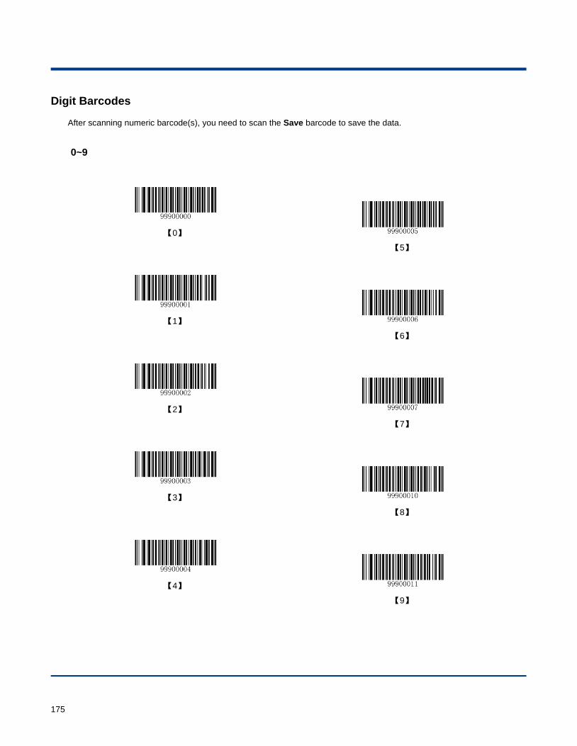
175
Digit Barcodes
After scanning numeric barcode(s), you need to scan the Save barcode to save the data.
0~9
【0】
【5】
【1】
【6】
【2】
【7】
【3】
【8】
【4】
【9】

176
A~F
【A】
【B】
【C】
【D】
【E】
【F】
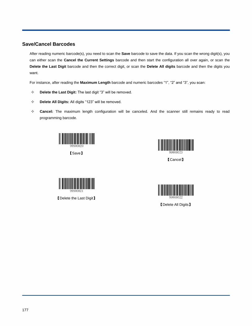
177
Save/Cancel Barcodes
After reading numeric barcode(s), you need to scan the Save barcode to save the data. If you scan the wrong digit(s), you
can either scan the Cancel the Current Settings barcode and then start the configuration all over again, or scan the
Delete the Last Digit barcode and then the correct digit, or scan the Delete All digits barcode and then the digits you
want.
For instance, after reading the Maximum Length barcode and numeric barcodes “1”, “2” and “3”, you scan:
Delete the Last Digit: The last digit “3” will be removed.
Delete All Digits: All digits “123” will be removed.
Cancel: The maximum length configuration will be canceled. And the scanner still remains ready to read
programming barcode.
【Save】
【Cancel】
【Delete the Last Digit】
【Delete All Digits】

【Exit Setup】
Headquarters / 总部
福建新大陆自动识别技术有限公司
地址:福建省福州市马尾区儒江西路 1 号新大陆科技园
邮编:350015
电话:+86 - (0) 591-83979222
传真:+86 - (0) 591-83979208
E-mail: [email protected]
WEB:www.nlscan.com
Newland Europe BV/ 欧洲新大陆有限公司
Rolweg 25, 4104 AV Culemborg, The Netherlands
TEL: +31 (0) 345 87 00 33
FAX: +31 (0) 345 87 00 39
Email: [email protected]
WEB: www.newland-id.com
Tech Support: [email protected]
Newland North America Inc. /北美新大陆有限公司
Address: 46559 Fremont Blvd., Fremont, CA 94538, USA
TEL: 510 490 3888
Fax: 510 490 3887
Email: [email protected]
WEB: www.newlandna.com
Newland Taiwan Inc. / 台灣新大陸資訊科技股份有限公司
7F-6, No. 268, Liancheng Rd., Jhonghe Dist. 235, New Taipei City,
Taiwan
新北市 235 中和區連城路 268 號 7 樓之 6 (遠東世紀廣場 J 棟)
TEL: +886 2 7731 5388
FAX: +886 2 7731 5389
Email: [email protected]
WEB: www.newland-id.com.tw